EP3521746A1 - A flat tube for a heat exchanger - Google Patents
A flat tube for a heat exchanger Download PDFInfo
- Publication number
- EP3521746A1 EP3521746A1 EP18461516.9A EP18461516A EP3521746A1 EP 3521746 A1 EP3521746 A1 EP 3521746A1 EP 18461516 A EP18461516 A EP 18461516A EP 3521746 A1 EP3521746 A1 EP 3521746A1
- Authority
- EP
- European Patent Office
- Prior art keywords
- layer
- flat tube
- tube
- heat exchanger
- flat
- Prior art date
- Legal status (The legal status is an assumption and is not a legal conclusion. Google has not performed a legal analysis and makes no representation as to the accuracy of the status listed.)
- Granted
Links
Images
Classifications
-
- F—MECHANICAL ENGINEERING; LIGHTING; HEATING; WEAPONS; BLASTING
- F28—HEAT EXCHANGE IN GENERAL
- F28D—HEAT-EXCHANGE APPARATUS, NOT PROVIDED FOR IN ANOTHER SUBCLASS, IN WHICH THE HEAT-EXCHANGE MEDIA DO NOT COME INTO DIRECT CONTACT
- F28D1/00—Heat-exchange apparatus having stationary conduit assemblies for one heat-exchange medium only, the media being in contact with different sides of the conduit wall, in which the other heat-exchange medium is a large body of fluid, e.g. domestic or motor car radiators
- F28D1/02—Heat-exchange apparatus having stationary conduit assemblies for one heat-exchange medium only, the media being in contact with different sides of the conduit wall, in which the other heat-exchange medium is a large body of fluid, e.g. domestic or motor car radiators with heat-exchange conduits immersed in the body of fluid
- F28D1/03—Heat-exchange apparatus having stationary conduit assemblies for one heat-exchange medium only, the media being in contact with different sides of the conduit wall, in which the other heat-exchange medium is a large body of fluid, e.g. domestic or motor car radiators with heat-exchange conduits immersed in the body of fluid with plate-like or laminated conduits
- F28D1/0391—Heat-exchange apparatus having stationary conduit assemblies for one heat-exchange medium only, the media being in contact with different sides of the conduit wall, in which the other heat-exchange medium is a large body of fluid, e.g. domestic or motor car radiators with heat-exchange conduits immersed in the body of fluid with plate-like or laminated conduits a single plate being bent to form one or more conduits
-
- F—MECHANICAL ENGINEERING; LIGHTING; HEATING; WEAPONS; BLASTING
- F28—HEAT EXCHANGE IN GENERAL
- F28F—DETAILS OF HEAT-EXCHANGE AND HEAT-TRANSFER APPARATUS, OF GENERAL APPLICATION
- F28F1/00—Tubular elements; Assemblies of tubular elements
- F28F1/003—Multiple wall conduits, e.g. for leak detection
-
- F—MECHANICAL ENGINEERING; LIGHTING; HEATING; WEAPONS; BLASTING
- F28—HEAT EXCHANGE IN GENERAL
- F28F—DETAILS OF HEAT-EXCHANGE AND HEAT-TRANSFER APPARATUS, OF GENERAL APPLICATION
- F28F1/00—Tubular elements; Assemblies of tubular elements
- F28F1/02—Tubular elements of cross-section which is non-circular
-
- F—MECHANICAL ENGINEERING; LIGHTING; HEATING; WEAPONS; BLASTING
- F28—HEAT EXCHANGE IN GENERAL
- F28F—DETAILS OF HEAT-EXCHANGE AND HEAT-TRANSFER APPARATUS, OF GENERAL APPLICATION
- F28F1/00—Tubular elements; Assemblies of tubular elements
- F28F1/10—Tubular elements and assemblies thereof with means for increasing heat-transfer area, e.g. with fins, with projections, with recesses
- F28F1/40—Tubular elements and assemblies thereof with means for increasing heat-transfer area, e.g. with fins, with projections, with recesses the means being only inside the tubular element
-
- F—MECHANICAL ENGINEERING; LIGHTING; HEATING; WEAPONS; BLASTING
- F28—HEAT EXCHANGE IN GENERAL
- F28F—DETAILS OF HEAT-EXCHANGE AND HEAT-TRANSFER APPARATUS, OF GENERAL APPLICATION
- F28F2225/00—Reinforcing means
- F28F2225/04—Reinforcing means for conduits
-
- F—MECHANICAL ENGINEERING; LIGHTING; HEATING; WEAPONS; BLASTING
- F28—HEAT EXCHANGE IN GENERAL
- F28F—DETAILS OF HEAT-EXCHANGE AND HEAT-TRANSFER APPARATUS, OF GENERAL APPLICATION
- F28F2275/00—Fastening; Joining
- F28F2275/06—Fastening; Joining by welding
-
- F—MECHANICAL ENGINEERING; LIGHTING; HEATING; WEAPONS; BLASTING
- F28—HEAT EXCHANGE IN GENERAL
- F28F—DETAILS OF HEAT-EXCHANGE AND HEAT-TRANSFER APPARATUS, OF GENERAL APPLICATION
- F28F3/00—Plate-like or laminated elements; Assemblies of plate-like or laminated elements
- F28F3/02—Elements or assemblies thereof with means for increasing heat-transfer area, e.g. with fins, with recesses, with corrugations
- F28F3/025—Elements or assemblies thereof with means for increasing heat-transfer area, e.g. with fins, with recesses, with corrugations the means being corrugated, plate-like elements
-
- F—MECHANICAL ENGINEERING; LIGHTING; HEATING; WEAPONS; BLASTING
- F28—HEAT EXCHANGE IN GENERAL
- F28F—DETAILS OF HEAT-EXCHANGE AND HEAT-TRANSFER APPARATUS, OF GENERAL APPLICATION
- F28F3/00—Plate-like or laminated elements; Assemblies of plate-like or laminated elements
- F28F3/02—Elements or assemblies thereof with means for increasing heat-transfer area, e.g. with fins, with recesses, with corrugations
- F28F3/06—Elements or assemblies thereof with means for increasing heat-transfer area, e.g. with fins, with recesses, with corrugations the means being attachable to the element
Definitions
- the invention relates to a tube for a heat exchanger. More particularly, the present invention relates to a flat tube for a heat exchanger used in the automotive industry.
- the heat exchange can take place between two fluids.
- the first fluid can be guided through a conduit formed by elements of the heat exchanger.
- These can be two manifolds connected fluidically by means of tubes.
- One of the fluids travels through these tubes between said manifolds.
- the tubes conduct the heat of the first fluid which is then transferred to the second fluid, or vice versa.
- the tubes can comprise inner fins, for example in form of corrugated sheets, the bent portions of which are in contact with said flat parallel walls of the flat tubes. These fins facilitate the heat exchange.
- inner fins for example in form of corrugated sheets, the bent portions of which are in contact with said flat parallel walls of the flat tubes.
- the object of the invention is a flat tube for a heat exchanger, formed by a sheet material and defined by a bottom wall, a top wall and two side walls, wherein at least one of the side walls comprises a first layer and a second layer of the sheet material, characterized in that the first layer has an curved portion forming a conduit together with the second layer.
- the curved portion has a circular cross-sectional shape defined by radius R.
- the first layer comprises brazed portions which form a connection with the second layer at the opposing sides of the conduit.
- the tube further comprises a fin in the space defined by its walls.
- the figures show a flat tube 10 for a heat exchanger.
- the heat exchanger can be a charge air cooler, water charge air cooler, condenser, radiator and the like.
- the flat tube 10 is formed by a sheet material and is defined by a bottom wall 11, a top wall 12 and two side walls 13.
- the side walls can be completely arcuate or can comprise a flat middle section.
- the distance between the bottom wall 11 and the top wall 12 defines the height direction H.
- the distance between the side walls 13 defines the width direction W. This width direction is to be understood to run parallel to the flat, parallel walls 11, 12, while the height direction is to be understood to run perpendicular to the flat, parallel walls 11, 12.
- At least one of the side walls 13 comprises a first layer 13a and a second layer 13b of the sheet material. This is achieved when the tube is manufactured by folding the sheet material into the shape of the flat tube, wherein two opposing ends of the sheet overlap onto each other.
- the tube can also be manufactured from two parts, i.e. a bottom part and a upper part, the side walls being created when respective walls are connected in a layered manner. In either case, the layers can be connected by brazing.
- the first layer 13a has an curved portion 14 forming a conduit 15 together with the second layer 13b.
- This conduit can be closed so that it can guide the fluid between the first layer 13a and the second layer 13b.
- the curved portion 14 protrudes into the inner space of the tube in the width direction and thereby prevents creation of the air bypass when a corrugated fin is placed in the tube.
- the degree of protrusion of the curved portion can be selected depending on the tube and dimensions, so that the unoccupied space between the fin 16 and side wall 13 is minimized.
- the curved portion 14 can have a circular cross-sectional shape defined by radius R.
- the R can be 2,4 mm.
- the first layer 13a comprises brazed portions 16 which form a connection with the second layer 13b at the opposing sides of the conduit 15, that is on the bottom and the top of the side wall 13 along the height direction. This provides improves the rigidness of the tube.
Landscapes
- Engineering & Computer Science (AREA)
- Physics & Mathematics (AREA)
- Thermal Sciences (AREA)
- Mechanical Engineering (AREA)
- General Engineering & Computer Science (AREA)
- Geometry (AREA)
- Heat-Exchange Devices With Radiators And Conduit Assemblies (AREA)
Abstract
Description
- The invention relates to a tube for a heat exchanger. More particularly, the present invention relates to a flat tube for a heat exchanger used in the automotive industry.
- In known heat exchangers, for example those used in the automotive industry, the heat exchange can take place between two fluids. The first fluid can be guided through a conduit formed by elements of the heat exchanger. These can be two manifolds connected fluidically by means of tubes. One of the fluids travels through these tubes between said manifolds. There can be spaces provided between the tubes, through which the second fluid can travel from one side of the tubes to the other. The tubes conduct the heat of the first fluid which is then transferred to the second fluid, or vice versa.
- There are known flat tubes, which in cross-section have an elongated shape defined by two parallel walls connected at their side edges by side walls of substantially smaller height. These tubes are generally placed one above the other so that their neighboring flat, parallel walls form channels for the second fluid. The tubes can comprise inner fins, for example in form of corrugated sheets, the bent portions of which are in contact with said flat parallel walls of the flat tubes. These fins facilitate the heat exchange. The example of such tubes is described in patent applications with publication numbers
EP1089047A2 orEP1906127A2 . - However, for the fins commonly used in the industry, the process of successfully filling the inner channel of the flat tube is complicated. In particular, a uniform distribution of the corrugated sheet in the flat tube poses difficulties which are hard to overcome in a cost-efficient manner. This is especially the case with flat tubes in which the side walls and their corner portions between the parallel flat walls and said side walls are made of layered tube material. In other words, the material thickness of the flat tube, due to its layered structure in those areas, varies towards its inner side, thereby hindering the uniformity of the fins distribution within the tube. For example, if the tube wall thickness is greater in the corner section in which normally the last wall portion of the fin of normal height would terminate, this last wall portion is made shorter. In other cases, the fin terminates at the last bent portion. In most cases this creates a space by the side wall of the tube which is unoccupied by the fin. This space creates a so called air bypass. The bypass does not contribute to the heat exchange in a manner similar to the rest of the flat tube.
- It is thus the aim of the invention to improve operation of the flat tube assembly comprising a flat tube and a fin inside said tube, and in particular to improve the heat exchange capabilities of the flat tube assembly. It is aimed to achieve this effect in a cost efficient manner which would be easy to implement.
- The object of the invention is a flat tube for a heat exchanger, formed by a sheet material and defined by a bottom wall, a top wall and two side walls, wherein at least one of the side walls comprises a first layer and a second layer of the sheet material, characterized in that the first layer has an curved portion forming a conduit together with the second layer.
- Preferably, the curved portion has a circular cross-sectional shape defined by radius R.
- Preferably, the first layer comprises brazed portions which form a connection with the second layer at the opposing sides of the conduit.
- Preferably, the tube further comprises a fin in the space defined by its walls.
- Preferably, the tube has a has a height H = 7,5 mm and width W = 100 mm, and a
curved portion 14 has a radius R = 2.4 mm. - Examples of the invention will be apparent from and described in detail with reference to the accompanying drawings, in which:
-
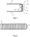
Fig. 1 shows the tube according to the invention. -
Fig. 2 shows the tube according to the invention with a fin. - The figures show a flat tube 10 for a heat exchanger. The heat exchanger can be a charge air cooler, water charge air cooler, condenser, radiator and the like. The flat tube 10 is formed by a sheet material and is defined by a
bottom wall 11, atop wall 12 and twoside walls 13. The side walls can be completely arcuate or can comprise a flat middle section. The distance between thebottom wall 11 and thetop wall 12 defines the height direction H. On the other hand, the distance between theside walls 13 defines the width direction W. This width direction is to be understood to run parallel to the flat,parallel walls parallel walls - At least one of the
side walls 13 comprises afirst layer 13a and asecond layer 13b of the sheet material. This is achieved when the tube is manufactured by folding the sheet material into the shape of the flat tube, wherein two opposing ends of the sheet overlap onto each other. The tube can also be manufactured from two parts, i.e. a bottom part and a upper part, the side walls being created when respective walls are connected in a layered manner. In either case, the layers can be connected by brazing. - According to the invention, the
first layer 13a has ancurved portion 14 forming aconduit 15 together with thesecond layer 13b. This conduit can be closed so that it can guide the fluid between thefirst layer 13a and thesecond layer 13b. Thecurved portion 14 protrudes into the inner space of the tube in the width direction and thereby prevents creation of the air bypass when a corrugated fin is placed in the tube. The degree of protrusion of the curved portion can be selected depending on the tube and dimensions, so that the unoccupied space between thefin 16 andside wall 13 is minimized. For example thecurved portion 14 can have a circular cross-sectional shape defined by radius R. For the tube of dimensions H = 7,5 mm and W = 100 mm, the R can be 2,4 mm. - In a preferred embodiment, the
first layer 13a comprises brazedportions 16 which form a connection with thesecond layer 13b at the opposing sides of theconduit 15, that is on the bottom and the top of theside wall 13 along the height direction. This provides improves the rigidness of the tube. - Other variations to the disclosed embodiments can be understood and effected by those skilled in the art in practicing the claimed invention, from a study of drawings, the disclosure, and the appended claims. The mere fact that certain measures are recited in mutually different dependent claims does not indicate that a combination of these measures cannot be used to the advantage.
Claims (5)
- A flat tube for a heat exchanger, formed by a sheet material and defined by a bottom wall 11, a top wall 12 and two side walls 13, wherein at least one of the side walls 13 comprises a first layer 13a and a second layer 13b of the sheet material, characterized in that the first layer 13a has an curved portion 14 forming a conduit 15 together with the second layer 13b.
- A flat tube according to claim 1, wherein the curved portion 14 has a circular cross-sectional shape defined by radius R.
- A flat tube according to any preceding claim, wherein the first layer 13a comprises brazed portions 16 which form a connection with the second layer 13b at the opposing sides of the conduit 15.
- A flat tube according to any preceding claim, wherein it further comprises a fin in the space defined by its walls 11, 12, 13.
- A flat tube according to claim 2, wherein the tube has a height H = 7,5 mm and width W = 100 mm, and a curved portion 14 has a radius R = 2.4 mm.
Priority Applications (2)
| Application Number | Priority Date | Filing Date | Title |
|---|---|---|---|
| EP18461516.9A EP3521746B1 (en) | 2018-02-06 | 2018-02-06 | A flat tube for a heat exchanger |
| CN201910106696.9A CN110118504B (en) | 2018-02-06 | 2019-02-02 | flat tube |
Applications Claiming Priority (1)
| Application Number | Priority Date | Filing Date | Title |
|---|---|---|---|
| EP18461516.9A EP3521746B1 (en) | 2018-02-06 | 2018-02-06 | A flat tube for a heat exchanger |
Publications (2)
| Publication Number | Publication Date |
|---|---|
| EP3521746A1 true EP3521746A1 (en) | 2019-08-07 |
| EP3521746B1 EP3521746B1 (en) | 2023-04-19 |
Family
ID=61187256
Family Applications (1)
| Application Number | Title | Priority Date | Filing Date |
|---|---|---|---|
| EP18461516.9A Active EP3521746B1 (en) | 2018-02-06 | 2018-02-06 | A flat tube for a heat exchanger |
Country Status (2)
| Country | Link |
|---|---|
| EP (1) | EP3521746B1 (en) |
| CN (1) | CN110118504B (en) |
Cited By (1)
| Publication number | Priority date | Publication date | Assignee | Title |
|---|---|---|---|---|
| LU101492B1 (en) * | 2019-11-25 | 2021-05-26 | Ht Holding Luxembourg S A | Flat heat exchanger tube |
Families Citing this family (1)
| Publication number | Priority date | Publication date | Assignee | Title |
|---|---|---|---|---|
| EP4553439A1 (en) * | 2023-11-10 | 2025-05-14 | Valeo Systemes Thermiques | A tube for a heat exchanger |
Citations (6)
| Publication number | Priority date | Publication date | Assignee | Title |
|---|---|---|---|---|
| EP0567399A1 (en) * | 1992-04-21 | 1993-10-27 | Valeo Thermique Moteur | Heat exchanger tube with integrated perturbation device |
| EP1089047A2 (en) | 1999-09-29 | 2001-04-04 | Valeo Inc. | Tube for heat exchanger |
| US20050161194A1 (en) * | 2002-05-03 | 2005-07-28 | Karsten Emrich | Heat exchanger, in particular charge-air cooler |
| EP1906127A2 (en) | 2006-09-29 | 2008-04-02 | International Truck Intellectual Property Company, LLC. | Corrosion resistant bi-metal charge air cooler |
| US20090166020A1 (en) * | 2004-07-28 | 2009-07-02 | Smith Paul R | Automotive heat exchanger assemblies having internal fins and methods of making the same |
| JP2012229853A (en) * | 2011-04-26 | 2012-11-22 | Showa Denko Kk | Heat exchanger |
Family Cites Families (4)
| Publication number | Priority date | Publication date | Assignee | Title |
|---|---|---|---|---|
| US8683690B2 (en) * | 2006-01-19 | 2014-04-01 | Modine Manufacturing Company | Flat tube, flat tube heat exchanger, and method of manufacturing same |
| DE102007006664A1 (en) * | 2007-02-10 | 2008-08-14 | Modine Manufacturing Co., Racine | Flat tube for heat exchanger |
| DE102012211350A1 (en) * | 2012-06-29 | 2014-01-02 | Behr Gmbh & Co. Kg | Flat tube and heat exchanger with such a flat tube |
| JP6843012B2 (en) * | 2017-07-14 | 2021-03-17 | 株式会社日本クライメイトシステムズ | Heat exchanger tube |
-
2018
- 2018-02-06 EP EP18461516.9A patent/EP3521746B1/en active Active
-
2019
- 2019-02-02 CN CN201910106696.9A patent/CN110118504B/en not_active Expired - Fee Related
Patent Citations (6)
| Publication number | Priority date | Publication date | Assignee | Title |
|---|---|---|---|---|
| EP0567399A1 (en) * | 1992-04-21 | 1993-10-27 | Valeo Thermique Moteur | Heat exchanger tube with integrated perturbation device |
| EP1089047A2 (en) | 1999-09-29 | 2001-04-04 | Valeo Inc. | Tube for heat exchanger |
| US20050161194A1 (en) * | 2002-05-03 | 2005-07-28 | Karsten Emrich | Heat exchanger, in particular charge-air cooler |
| US20090166020A1 (en) * | 2004-07-28 | 2009-07-02 | Smith Paul R | Automotive heat exchanger assemblies having internal fins and methods of making the same |
| EP1906127A2 (en) | 2006-09-29 | 2008-04-02 | International Truck Intellectual Property Company, LLC. | Corrosion resistant bi-metal charge air cooler |
| JP2012229853A (en) * | 2011-04-26 | 2012-11-22 | Showa Denko Kk | Heat exchanger |
Cited By (3)
| Publication number | Priority date | Publication date | Assignee | Title |
|---|---|---|---|---|
| LU101492B1 (en) * | 2019-11-25 | 2021-05-26 | Ht Holding Luxembourg S A | Flat heat exchanger tube |
| WO2021105200A1 (en) * | 2019-11-25 | 2021-06-03 | Ht Holding Luxembourg S.A. | Flat heat exchanger tube |
| US12209815B2 (en) | 2019-11-25 | 2025-01-28 | Estra Automotive Systems Luxembourg S.A.R.L. | Flat heat exchanger tube |
Also Published As
| Publication number | Publication date |
|---|---|
| CN110118504B (en) | 2023-04-28 |
| EP3521746B1 (en) | 2023-04-19 |
| CN110118504A (en) | 2019-08-13 |
Similar Documents
| Publication | Publication Date | Title |
|---|---|---|
| EP2395308B1 (en) | Heat exchanger | |
| JP2009063228A (en) | Flat heat transfer tube | |
| JP5945806B2 (en) | Finned tube heat exchanger | |
| US9593889B2 (en) | Heat exchanger construction | |
| US11226161B2 (en) | Heat exchanger | |
| CN104937362B (en) | heat exchanger | |
| US10508870B2 (en) | B-tube reform for improved thermal cycle performance | |
| JP2017531149A (en) | Header plate, header box and heat exchanger for heat exchanger | |
| JP6160385B2 (en) | Laminate heat exchanger | |
| EP3521746B1 (en) | A flat tube for a heat exchanger | |
| WO2021049505A1 (en) | Tank structure of heat exchanger | |
| JPH0493596A (en) | Core structure of stacked type heat exchanger | |
| JP2007292453A (en) | Louvered fin for heat exchanger | |
| WO2013018270A1 (en) | Fin-tube heat exchanger | |
| WO2019163973A1 (en) | Tank structure for heat exchanger | |
| EP3521745B1 (en) | A flat tube assembly for a heat exchanger | |
| US9453599B2 (en) | Bi-channel coolant tube having crossover channels to allow coolant interaction | |
| JP2012154520A (en) | Tube for heat exchanger, and heat exchanger | |
| CN114945793A (en) | heat exchanger | |
| US20200271393A1 (en) | Heat exchanger tube | |
| EP4497984A1 (en) | A flat tube for a heat exchanger | |
| JP6083272B2 (en) | Heat exchanger | |
| JP2011163621A (en) | Heat exchanger | |
| KR20170044965A (en) | A tube of heat exchanger | |
| KR101977854B1 (en) | A fin of heat exchanger |
Legal Events
| Date | Code | Title | Description |
|---|---|---|---|
| PUAI | Public reference made under article 153(3) epc to a published international application that has entered the european phase |
Free format text: ORIGINAL CODE: 0009012 |
|
| STAA | Information on the status of an ep patent application or granted ep patent |
Free format text: STATUS: THE APPLICATION HAS BEEN PUBLISHED |
|
| AK | Designated contracting states |
Kind code of ref document: A1 Designated state(s): AL AT BE BG CH CY CZ DE DK EE ES FI FR GB GR HR HU IE IS IT LI LT LU LV MC MK MT NL NO PL PT RO RS SE SI SK SM TR |
|
| AX | Request for extension of the european patent |
Extension state: BA ME |
|
| STAA | Information on the status of an ep patent application or granted ep patent |
Free format text: STATUS: REQUEST FOR EXAMINATION WAS MADE |
|
| 17P | Request for examination filed |
Effective date: 20200121 |
|
| RBV | Designated contracting states (corrected) |
Designated state(s): AL AT BE BG CH CY CZ DE DK EE ES FI FR GB GR HR HU IE IS IT LI LT LU LV MC MK MT NL NO PL PT RO RS SE SI SK SM TR |
|
| STAA | Information on the status of an ep patent application or granted ep patent |
Free format text: STATUS: EXAMINATION IS IN PROGRESS |
|
| 17Q | First examination report despatched |
Effective date: 20210219 |
|
| GRAP | Despatch of communication of intention to grant a patent |
Free format text: ORIGINAL CODE: EPIDOSNIGR1 |
|
| STAA | Information on the status of an ep patent application or granted ep patent |
Free format text: STATUS: GRANT OF PATENT IS INTENDED |
|
| INTG | Intention to grant announced |
Effective date: 20221206 |
|
| GRAS | Grant fee paid |
Free format text: ORIGINAL CODE: EPIDOSNIGR3 |
|
| GRAA | (expected) grant |
Free format text: ORIGINAL CODE: 0009210 |
|
| STAA | Information on the status of an ep patent application or granted ep patent |
Free format text: STATUS: THE PATENT HAS BEEN GRANTED |
|
| AK | Designated contracting states |
Kind code of ref document: B1 Designated state(s): AL AT BE BG CH CY CZ DE DK EE ES FI FR GB GR HR HU IE IS IT LI LT LU LV MC MK MT NL NO PL PT RO RS SE SI SK SM TR |
|
| REG | Reference to a national code |
Ref country code: GB Ref legal event code: FG4D |
|
| REG | Reference to a national code |
Ref country code: DE Ref legal event code: R096 Ref document number: 602018048538 Country of ref document: DE |
|
| REG | Reference to a national code |
Ref country code: CH Ref legal event code: EP |
|
| REG | Reference to a national code |
Ref country code: IE Ref legal event code: FG4D |
|
| REG | Reference to a national code |
Ref country code: AT Ref legal event code: REF Ref document number: 1561492 Country of ref document: AT Kind code of ref document: T Effective date: 20230515 |
|
| P01 | Opt-out of the competence of the unified patent court (upc) registered |
Effective date: 20230528 |
|
| REG | Reference to a national code |
Ref country code: LT Ref legal event code: MG9D |
|
| REG | Reference to a national code |
Ref country code: NL Ref legal event code: MP Effective date: 20230419 |
|
| REG | Reference to a national code |
Ref country code: AT Ref legal event code: MK05 Ref document number: 1561492 Country of ref document: AT Kind code of ref document: T Effective date: 20230419 |
|
| PG25 | Lapsed in a contracting state [announced via postgrant information from national office to epo] |
Ref country code: NL Free format text: LAPSE BECAUSE OF FAILURE TO SUBMIT A TRANSLATION OF THE DESCRIPTION OR TO PAY THE FEE WITHIN THE PRESCRIBED TIME-LIMIT Effective date: 20230419 |
|
| PG25 | Lapsed in a contracting state [announced via postgrant information from national office to epo] |
Ref country code: SE Free format text: LAPSE BECAUSE OF FAILURE TO SUBMIT A TRANSLATION OF THE DESCRIPTION OR TO PAY THE FEE WITHIN THE PRESCRIBED TIME-LIMIT Effective date: 20230419 Ref country code: PT Free format text: LAPSE BECAUSE OF FAILURE TO SUBMIT A TRANSLATION OF THE DESCRIPTION OR TO PAY THE FEE WITHIN THE PRESCRIBED TIME-LIMIT Effective date: 20230821 Ref country code: NO Free format text: LAPSE BECAUSE OF FAILURE TO SUBMIT A TRANSLATION OF THE DESCRIPTION OR TO PAY THE FEE WITHIN THE PRESCRIBED TIME-LIMIT Effective date: 20230719 Ref country code: ES Free format text: LAPSE BECAUSE OF FAILURE TO SUBMIT A TRANSLATION OF THE DESCRIPTION OR TO PAY THE FEE WITHIN THE PRESCRIBED TIME-LIMIT Effective date: 20230419 Ref country code: AT Free format text: LAPSE BECAUSE OF FAILURE TO SUBMIT A TRANSLATION OF THE DESCRIPTION OR TO PAY THE FEE WITHIN THE PRESCRIBED TIME-LIMIT Effective date: 20230419 |
|
| PG25 | Lapsed in a contracting state [announced via postgrant information from national office to epo] |
Ref country code: RS Free format text: LAPSE BECAUSE OF FAILURE TO SUBMIT A TRANSLATION OF THE DESCRIPTION OR TO PAY THE FEE WITHIN THE PRESCRIBED TIME-LIMIT Effective date: 20230419 Ref country code: PL Free format text: LAPSE BECAUSE OF FAILURE TO SUBMIT A TRANSLATION OF THE DESCRIPTION OR TO PAY THE FEE WITHIN THE PRESCRIBED TIME-LIMIT Effective date: 20230419 Ref country code: LV Free format text: LAPSE BECAUSE OF FAILURE TO SUBMIT A TRANSLATION OF THE DESCRIPTION OR TO PAY THE FEE WITHIN THE PRESCRIBED TIME-LIMIT Effective date: 20230419 Ref country code: LT Free format text: LAPSE BECAUSE OF FAILURE TO SUBMIT A TRANSLATION OF THE DESCRIPTION OR TO PAY THE FEE WITHIN THE PRESCRIBED TIME-LIMIT Effective date: 20230419 Ref country code: IS Free format text: LAPSE BECAUSE OF FAILURE TO SUBMIT A TRANSLATION OF THE DESCRIPTION OR TO PAY THE FEE WITHIN THE PRESCRIBED TIME-LIMIT Effective date: 20230819 Ref country code: HR Free format text: LAPSE BECAUSE OF FAILURE TO SUBMIT A TRANSLATION OF THE DESCRIPTION OR TO PAY THE FEE WITHIN THE PRESCRIBED TIME-LIMIT Effective date: 20230419 Ref country code: GR Free format text: LAPSE BECAUSE OF FAILURE TO SUBMIT A TRANSLATION OF THE DESCRIPTION OR TO PAY THE FEE WITHIN THE PRESCRIBED TIME-LIMIT Effective date: 20230720 Ref country code: AL Free format text: LAPSE BECAUSE OF FAILURE TO SUBMIT A TRANSLATION OF THE DESCRIPTION OR TO PAY THE FEE WITHIN THE PRESCRIBED TIME-LIMIT Effective date: 20230419 |
|
| PG25 | Lapsed in a contracting state [announced via postgrant information from national office to epo] |
Ref country code: FI Free format text: LAPSE BECAUSE OF FAILURE TO SUBMIT A TRANSLATION OF THE DESCRIPTION OR TO PAY THE FEE WITHIN THE PRESCRIBED TIME-LIMIT Effective date: 20230419 |
|
| PG25 | Lapsed in a contracting state [announced via postgrant information from national office to epo] |
Ref country code: SK Free format text: LAPSE BECAUSE OF FAILURE TO SUBMIT A TRANSLATION OF THE DESCRIPTION OR TO PAY THE FEE WITHIN THE PRESCRIBED TIME-LIMIT Effective date: 20230419 |
|
| REG | Reference to a national code |
Ref country code: DE Ref legal event code: R097 Ref document number: 602018048538 Country of ref document: DE |
|
| PG25 | Lapsed in a contracting state [announced via postgrant information from national office to epo] |
Ref country code: SM Free format text: LAPSE BECAUSE OF FAILURE TO SUBMIT A TRANSLATION OF THE DESCRIPTION OR TO PAY THE FEE WITHIN THE PRESCRIBED TIME-LIMIT Effective date: 20230419 Ref country code: SK Free format text: LAPSE BECAUSE OF FAILURE TO SUBMIT A TRANSLATION OF THE DESCRIPTION OR TO PAY THE FEE WITHIN THE PRESCRIBED TIME-LIMIT Effective date: 20230419 Ref country code: RO Free format text: LAPSE BECAUSE OF FAILURE TO SUBMIT A TRANSLATION OF THE DESCRIPTION OR TO PAY THE FEE WITHIN THE PRESCRIBED TIME-LIMIT Effective date: 20230419 Ref country code: EE Free format text: LAPSE BECAUSE OF FAILURE TO SUBMIT A TRANSLATION OF THE DESCRIPTION OR TO PAY THE FEE WITHIN THE PRESCRIBED TIME-LIMIT Effective date: 20230419 Ref country code: DK Free format text: LAPSE BECAUSE OF FAILURE TO SUBMIT A TRANSLATION OF THE DESCRIPTION OR TO PAY THE FEE WITHIN THE PRESCRIBED TIME-LIMIT Effective date: 20230419 Ref country code: CZ Free format text: LAPSE BECAUSE OF FAILURE TO SUBMIT A TRANSLATION OF THE DESCRIPTION OR TO PAY THE FEE WITHIN THE PRESCRIBED TIME-LIMIT Effective date: 20230419 |
|
| PLBE | No opposition filed within time limit |
Free format text: ORIGINAL CODE: 0009261 |
|
| STAA | Information on the status of an ep patent application or granted ep patent |
Free format text: STATUS: NO OPPOSITION FILED WITHIN TIME LIMIT |
|
| 26N | No opposition filed |
Effective date: 20240122 |
|
| PGFP | Annual fee paid to national office [announced via postgrant information from national office to epo] |
Ref country code: DE Payment date: 20240213 Year of fee payment: 7 |
|
| PG25 | Lapsed in a contracting state [announced via postgrant information from national office to epo] |
Ref country code: SI Free format text: LAPSE BECAUSE OF FAILURE TO SUBMIT A TRANSLATION OF THE DESCRIPTION OR TO PAY THE FEE WITHIN THE PRESCRIBED TIME-LIMIT Effective date: 20230419 |
|
| PG25 | Lapsed in a contracting state [announced via postgrant information from national office to epo] |
Ref country code: SI Free format text: LAPSE BECAUSE OF FAILURE TO SUBMIT A TRANSLATION OF THE DESCRIPTION OR TO PAY THE FEE WITHIN THE PRESCRIBED TIME-LIMIT Effective date: 20230419 Ref country code: IT Free format text: LAPSE BECAUSE OF FAILURE TO SUBMIT A TRANSLATION OF THE DESCRIPTION OR TO PAY THE FEE WITHIN THE PRESCRIBED TIME-LIMIT Effective date: 20230419 |
|
| PGFP | Annual fee paid to national office [announced via postgrant information from national office to epo] |
Ref country code: FR Payment date: 20240228 Year of fee payment: 7 |
|
| PG25 | Lapsed in a contracting state [announced via postgrant information from national office to epo] |
Ref country code: MC Free format text: LAPSE BECAUSE OF FAILURE TO SUBMIT A TRANSLATION OF THE DESCRIPTION OR TO PAY THE FEE WITHIN THE PRESCRIBED TIME-LIMIT Effective date: 20230419 |
|
| REG | Reference to a national code |
Ref country code: CH Ref legal event code: PL |
|
| PG25 | Lapsed in a contracting state [announced via postgrant information from national office to epo] |
Ref country code: LU Free format text: LAPSE BECAUSE OF NON-PAYMENT OF DUE FEES Effective date: 20240206 |
|
| PG25 | Lapsed in a contracting state [announced via postgrant information from national office to epo] |
Ref country code: CH Free format text: LAPSE BECAUSE OF NON-PAYMENT OF DUE FEES Effective date: 20240229 |
|
| GBPC | Gb: european patent ceased through non-payment of renewal fee |
Effective date: 20240206 |
|
| PG25 | Lapsed in a contracting state [announced via postgrant information from national office to epo] |
Ref country code: LU Free format text: LAPSE BECAUSE OF NON-PAYMENT OF DUE FEES Effective date: 20240206 Ref country code: CH Free format text: LAPSE BECAUSE OF NON-PAYMENT OF DUE FEES Effective date: 20240229 |
|
| PG25 | Lapsed in a contracting state [announced via postgrant information from national office to epo] |
Ref country code: BG Free format text: LAPSE BECAUSE OF FAILURE TO SUBMIT A TRANSLATION OF THE DESCRIPTION OR TO PAY THE FEE WITHIN THE PRESCRIBED TIME-LIMIT Effective date: 20230419 |
|
| PG25 | Lapsed in a contracting state [announced via postgrant information from national office to epo] |
Ref country code: BG Free format text: LAPSE BECAUSE OF FAILURE TO SUBMIT A TRANSLATION OF THE DESCRIPTION OR TO PAY THE FEE WITHIN THE PRESCRIBED TIME-LIMIT Effective date: 20230419 |
|
| REG | Reference to a national code |
Ref country code: BE Ref legal event code: MM Effective date: 20240229 |
|
| PG25 | Lapsed in a contracting state [announced via postgrant information from national office to epo] |
Ref country code: BE Free format text: LAPSE BECAUSE OF NON-PAYMENT OF DUE FEES Effective date: 20240229 |
|
| PG25 | Lapsed in a contracting state [announced via postgrant information from national office to epo] |
Ref country code: GB Free format text: LAPSE BECAUSE OF NON-PAYMENT OF DUE FEES Effective date: 20240206 |
|
| PG25 | Lapsed in a contracting state [announced via postgrant information from national office to epo] |
Ref country code: IE Free format text: LAPSE BECAUSE OF NON-PAYMENT OF DUE FEES Effective date: 20240206 |
|
| PG25 | Lapsed in a contracting state [announced via postgrant information from national office to epo] |
Ref country code: IE Free format text: LAPSE BECAUSE OF NON-PAYMENT OF DUE FEES Effective date: 20240206 Ref country code: GB Free format text: LAPSE BECAUSE OF NON-PAYMENT OF DUE FEES Effective date: 20240206 Ref country code: BE Free format text: LAPSE BECAUSE OF NON-PAYMENT OF DUE FEES Effective date: 20240229 |
|
| PG25 | Lapsed in a contracting state [announced via postgrant information from national office to epo] |
Ref country code: CY Free format text: LAPSE BECAUSE OF FAILURE TO SUBMIT A TRANSLATION OF THE DESCRIPTION OR TO PAY THE FEE WITHIN THE PRESCRIBED TIME-LIMIT; INVALID AB INITIO Effective date: 20180206 |
|
| REG | Reference to a national code |
Ref country code: DE Ref legal event code: R119 Ref document number: 602018048538 Country of ref document: DE |
|
| PG25 | Lapsed in a contracting state [announced via postgrant information from national office to epo] |
Ref country code: HU Free format text: LAPSE BECAUSE OF FAILURE TO SUBMIT A TRANSLATION OF THE DESCRIPTION OR TO PAY THE FEE WITHIN THE PRESCRIBED TIME-LIMIT; INVALID AB INITIO Effective date: 20180206 |
|
| PG25 | Lapsed in a contracting state [announced via postgrant information from national office to epo] |
Ref country code: TR Free format text: LAPSE BECAUSE OF FAILURE TO SUBMIT A TRANSLATION OF THE DESCRIPTION OR TO PAY THE FEE WITHIN THE PRESCRIBED TIME-LIMIT Effective date: 20230419 |
|
| PG25 | Lapsed in a contracting state [announced via postgrant information from national office to epo] |
Ref country code: DE Free format text: LAPSE BECAUSE OF NON-PAYMENT OF DUE FEES Effective date: 20250902 |
|
| PG25 | Lapsed in a contracting state [announced via postgrant information from national office to epo] |
Ref country code: FR Free format text: LAPSE BECAUSE OF NON-PAYMENT OF DUE FEES Effective date: 20250228 |