EP3521742A1 - Heat exchanger - Google Patents
Heat exchanger Download PDFInfo
- Publication number
- EP3521742A1 EP3521742A1 EP18461513.6A EP18461513A EP3521742A1 EP 3521742 A1 EP3521742 A1 EP 3521742A1 EP 18461513 A EP18461513 A EP 18461513A EP 3521742 A1 EP3521742 A1 EP 3521742A1
- Authority
- EP
- European Patent Office
- Prior art keywords
- heat exchanger
- flow passage
- plate
- flow
- exchanger body
- Prior art date
- Legal status (The legal status is an assumption and is not a legal conclusion. Google has not performed a legal analysis and makes no representation as to the accuracy of the status listed.)
- Granted
Links
Images




Classifications
-
- F—MECHANICAL ENGINEERING; LIGHTING; HEATING; WEAPONS; BLASTING
- F28—HEAT EXCHANGE IN GENERAL
- F28D—HEAT-EXCHANGE APPARATUS, NOT PROVIDED FOR IN ANOTHER SUBCLASS, IN WHICH THE HEAT-EXCHANGE MEDIA DO NOT COME INTO DIRECT CONTACT
- F28D9/00—Heat-exchange apparatus having stationary plate-like or laminated conduit assemblies for both heat-exchange media, the media being in contact with different sides of a conduit wall
- F28D9/0093—Multi-circuit heat-exchangers, e.g. integrating different heat exchange sections in the same unit or heat-exchangers for more than two fluids
-
- F—MECHANICAL ENGINEERING; LIGHTING; HEATING; WEAPONS; BLASTING
- F28—HEAT EXCHANGE IN GENERAL
- F28D—HEAT-EXCHANGE APPARATUS, NOT PROVIDED FOR IN ANOTHER SUBCLASS, IN WHICH THE HEAT-EXCHANGE MEDIA DO NOT COME INTO DIRECT CONTACT
- F28D7/00—Heat-exchange apparatus having stationary tubular conduit assemblies for both heat-exchange media, the media being in contact with different sides of a conduit wall
- F28D7/10—Heat-exchange apparatus having stationary tubular conduit assemblies for both heat-exchange media, the media being in contact with different sides of a conduit wall the conduits being arranged one within the other, e.g. concentrically
- F28D7/103—Heat-exchange apparatus having stationary tubular conduit assemblies for both heat-exchange media, the media being in contact with different sides of a conduit wall the conduits being arranged one within the other, e.g. concentrically consisting of more than two coaxial conduits or modules of more than two coaxial conduits
-
- F—MECHANICAL ENGINEERING; LIGHTING; HEATING; WEAPONS; BLASTING
- F28—HEAT EXCHANGE IN GENERAL
- F28D—HEAT-EXCHANGE APPARATUS, NOT PROVIDED FOR IN ANOTHER SUBCLASS, IN WHICH THE HEAT-EXCHANGE MEDIA DO NOT COME INTO DIRECT CONTACT
- F28D9/00—Heat-exchange apparatus having stationary plate-like or laminated conduit assemblies for both heat-exchange media, the media being in contact with different sides of a conduit wall
- F28D9/0012—Heat-exchange apparatus having stationary plate-like or laminated conduit assemblies for both heat-exchange media, the media being in contact with different sides of a conduit wall the apparatus having an annular form
-
- F—MECHANICAL ENGINEERING; LIGHTING; HEATING; WEAPONS; BLASTING
- F28—HEAT EXCHANGE IN GENERAL
- F28D—HEAT-EXCHANGE APPARATUS, NOT PROVIDED FOR IN ANOTHER SUBCLASS, IN WHICH THE HEAT-EXCHANGE MEDIA DO NOT COME INTO DIRECT CONTACT
- F28D9/00—Heat-exchange apparatus having stationary plate-like or laminated conduit assemblies for both heat-exchange media, the media being in contact with different sides of a conduit wall
- F28D9/0012—Heat-exchange apparatus having stationary plate-like or laminated conduit assemblies for both heat-exchange media, the media being in contact with different sides of a conduit wall the apparatus having an annular form
- F28D9/0018—Heat-exchange apparatus having stationary plate-like or laminated conduit assemblies for both heat-exchange media, the media being in contact with different sides of a conduit wall the apparatus having an annular form without any annular circulation of the heat exchange media
-
- F—MECHANICAL ENGINEERING; LIGHTING; HEATING; WEAPONS; BLASTING
- F28—HEAT EXCHANGE IN GENERAL
- F28D—HEAT-EXCHANGE APPARATUS, NOT PROVIDED FOR IN ANOTHER SUBCLASS, IN WHICH THE HEAT-EXCHANGE MEDIA DO NOT COME INTO DIRECT CONTACT
- F28D9/00—Heat-exchange apparatus having stationary plate-like or laminated conduit assemblies for both heat-exchange media, the media being in contact with different sides of a conduit wall
- F28D9/0031—Heat-exchange apparatus having stationary plate-like or laminated conduit assemblies for both heat-exchange media, the media being in contact with different sides of a conduit wall the conduits for one heat-exchange medium being formed by paired plates touching each other
- F28D9/0037—Heat-exchange apparatus having stationary plate-like or laminated conduit assemblies for both heat-exchange media, the media being in contact with different sides of a conduit wall the conduits for one heat-exchange medium being formed by paired plates touching each other the conduits for the other heat-exchange medium also being formed by paired plates touching each other
-
- F—MECHANICAL ENGINEERING; LIGHTING; HEATING; WEAPONS; BLASTING
- F28—HEAT EXCHANGE IN GENERAL
- F28F—DETAILS OF HEAT-EXCHANGE AND HEAT-TRANSFER APPARATUS, OF GENERAL APPLICATION
- F28F3/00—Plate-like or laminated elements; Assemblies of plate-like or laminated elements
- F28F3/08—Elements constructed for building-up into stacks, e.g. capable of being taken apart for cleaning
- F28F3/086—Elements constructed for building-up into stacks, e.g. capable of being taken apart for cleaning having one or more openings therein forming tubular heat-exchange passages
-
- F—MECHANICAL ENGINEERING; LIGHTING; HEATING; WEAPONS; BLASTING
- F28—HEAT EXCHANGE IN GENERAL
- F28D—HEAT-EXCHANGE APPARATUS, NOT PROVIDED FOR IN ANOTHER SUBCLASS, IN WHICH THE HEAT-EXCHANGE MEDIA DO NOT COME INTO DIRECT CONTACT
- F28D21/00—Heat-exchange apparatus not covered by any of the groups F28D1/00 - F28D20/00
- F28D2021/0019—Other heat exchangers for particular applications; Heat exchange systems not otherwise provided for
- F28D2021/0021—Other heat exchangers for particular applications; Heat exchange systems not otherwise provided for for aircrafts or cosmonautics
-
- F—MECHANICAL ENGINEERING; LIGHTING; HEATING; WEAPONS; BLASTING
- F28—HEAT EXCHANGE IN GENERAL
- F28D—HEAT-EXCHANGE APPARATUS, NOT PROVIDED FOR IN ANOTHER SUBCLASS, IN WHICH THE HEAT-EXCHANGE MEDIA DO NOT COME INTO DIRECT CONTACT
- F28D21/00—Heat-exchange apparatus not covered by any of the groups F28D1/00 - F28D20/00
- F28D2021/0019—Other heat exchangers for particular applications; Heat exchange systems not otherwise provided for
- F28D2021/0026—Other heat exchangers for particular applications; Heat exchange systems not otherwise provided for for combustion engines, e.g. for gas turbines or for Stirling engines
-
- F—MECHANICAL ENGINEERING; LIGHTING; HEATING; WEAPONS; BLASTING
- F28—HEAT EXCHANGE IN GENERAL
- F28F—DETAILS OF HEAT-EXCHANGE AND HEAT-TRANSFER APPARATUS, OF GENERAL APPLICATION
- F28F2215/00—Fins
- F28F2215/10—Secondary fins, e.g. projections or recesses on main fins
Definitions
- the number and form of the fins can also be varied to optimise heat exchange performance for a desired used.
- adjacent plates may be joined together by brazing. This may provide fluid tight joins between the plates in each of the first, second and third flow passages.
- a third annular ring or wall 32 is concentric with and spaced radially outwardly from the second annular ring 28 so as to form an annular gap or gap 35 (which forms part of a third flow passage 62) between the second and third annular rings 28, 32.
- the third annular ring 32 is formed to extend over the full thickness t of the plate 20, having a thickness t in the example shown.
- a further set of straight radial spokes or fins 34 extends between the second and third annular rings 28, 32. In the example shown, thirty straight radial fins 34 are evenly distributed about the perimeter 37 of the second annular ring 28.
Landscapes
- Engineering & Computer Science (AREA)
- Physics & Mathematics (AREA)
- Thermal Sciences (AREA)
- Mechanical Engineering (AREA)
- General Engineering & Computer Science (AREA)
- Heat-Exchange Devices With Radiators And Conduit Assemblies (AREA)
Abstract
Description
- The present disclosure relates to heat exchangers and to a plate for use in a heat exchanger.
- Heat exchangers are typically used to transfer heat from one medium to another. In the aerospace industry, heat exchangers can be used for example to heat fuel before being combusted in a turbine engine and to cool or heat air for use, for example, in conditioning aircraft wings or cooling parts of turbine engines.
- There is a need to provide a low weight, high strength heat exchanger for heat exchange between three or more fluid flows which can be manufactured to a desired size and shape whilst providing efficient heat exchange between the fluids.
- The present disclosure seeks to address these challenges.
- According to an aspect of the present disclosure there is provided a plate for use in a heat exchanger, the plate comprising:
- a first surface;
- a second surface extending parallel to and spaced from the first surface;
- first, second and third discrete flow passages passing through the plate from the first surface to the second surface,
- the second flow passage extending around the first flow passage and the third flow passage extending around the second flow passage;
- a plurality of fins extending parallel to the first surface across the third flow passage and having a first fin surface extending parallel to the first surface of the plate and a second fin surface extending parallel to and spaced from the first fin surface; and
- one or more pins protruding from the first fin surface of at least some of the fins, the pins extending away from the second fin surfaces,
- wherein a first distance from the second fin surfaces to an end of the pins removed from the first fin surfaces is less than or equal to a second distance from the second surface of the plate to the first surface thereof.
- It will be understood that the first, second and third flow passages each extend through the plate. The plate can be relatively simply manufactured and can then be assembled with other plates to form a heat exchanger matrix without the need for any further machining. Further, the shape of the plate and the passages within it can be varied as required to provide a heat exchanger matrix having an optimum shape and performance for a desired use.
- The number and form of the fins can also be varied to optimise heat exchange performance for a desired used.
- In one preferred example, at least one pin may be provided on the first fin surface of each of the fins.
- The plate may be made from any suitable material. In preferred examples, the plate is made from metal.
- The first flow passage could extend through the centre of the plate, however the plate may further comprise a solid central portion extending from the first surface to the second surface, and the first flow passage may extend around the solid central portion. The solid central portion may increase the strength of the plate and improve the heat exchange efficiency when used in a heat exchanger.
- In any example of the present disclosure, the plate may further comprise a plurality of second fins extending across the first flow passage from the solid central portion towards the second flow passage. The second fins may further improve the strength of the plate and the heat exchange capacity of the heat exchanger when assembled.
- In any example of the present disclosure, the second fins may have an undulating form. In one preferred example, the fins may undulate parallel to the second surface of the plate along the length of the second fins. The undulating form may increase the turbulence in the fluid flowing through the first flow passage in use, thus improving the heat exchange efficiency of the heat exchanger when assembled.
- In any example of the present disclosure, the pins may be twisted in a direction perpendicular to the direction of the flow of fluid through the third flow passage in use. This again may increase the turbulence in the fluid flowing through the third flow passage in use, thus improving the heat exchange efficiency of the heat exchanger when assembled.
- In any example of the present disclosure, the third flow passage may comprise a gap formed by a wall extending outwardly of and around the second flow passage, and first and second outer portions formed by walls extending outwardly from the wall and re-joining therewith on either side thereof, wherein the sections of the wall which are internal of the first and second outer portions extend over a third distance which is less than the second distance from the first surface to the second surface of the plate, and the other sections of the wall and the walls extending outwardly from the wall on either side thereof extend from the first surface to the second surface of the plate.
- Although the wall could take many forms depending on the use for which the plate and heat exchanger were designed, such as for example an elliptical shape, in one preferred example the wall may comprise an annular ring.
- In any example of the present disclosure, the plate may be formed by etching, or any method by which sections of the plate are removed to form the required shape, such as, for example, chemical etching. Alternatively, the plate may be formed by additive manufacturing, 3D printing or powder metallurgy.
- The plate and the flow passages could take many possible forms. In any example of the present disclosure however, the first and second flow passages may be curved, e.g. elliptical. In a more preferred example however, the first and second flow passages may be annular in shape. The curved shape of the first, second and/or third flow passages will result in increased strength of the plate and of the heat exchanger when assembled.
- From a further aspect, the present disclosure may provide a heat exchanger body comprising a number of plates as claimed in any preceding claim, wherein the plates are arranged adjacent to one another along a longitudinal axis of the heat exchanger such that the first surface of a first plate is in contact with and fixed to the second surface of an adjacent plate, and
the first, second and third flow passages of adjacent plates are joined together to form continuous first, second and third flow passages extending through the heat exchanger body. - In a preferred example of the present disclosure, adjacent plates may be joined together by brazing. This may provide fluid tight joins between the plates in each of the first, second and third flow passages.
- The heat exchanger body of the present disclosure may further comprise:
- a first inlet to the first flow passage provided at a first longitudinal end of the heat exchanger body and a first outlet from the first flow passage provided at a second longitudinal end of the heat exchanger body; and
- a second inlet to the second flow passage provided at the second longitudinal end of the heat exchanger body and a second outlet from the second flow passage provided at the first longitudinal end of the heat exchanger body such that in use, fluid will flow through the second flow passage in a direction opposite to the direction of flow of fluid through the first flow passage.
- The heat exchanger body of the present disclosure may further comprise:
- a third inlet to the third flow passage provided at the first longitudinal end of the heat exchanger body and a third outlet from the third flow passage provided at the first longitudinal end of the heat exchanger body.
- The third inlet may be provided on a first side of the heat exchanger body and the third outlet may be provided on a second opposite side of the heat exchanger body such that in use, fluid will flow through the third flow passage in the first longitudinal direction on the first side of the heat exchanger body, flow around the second passage in a direction perpendicular to the first longitudinal direction, and then flow through the third flow passage to the outlet in the second longitudinal direction on the second side of the heat exchanger body.
- From a further aspect of the present disclosure there is provided a method of exchanging heat between fluid flows, the method comprising:
- passing a first fluid flow in a first direction through a first flow passage extending through a plurality of plates in a heat exchanger body;
- passing a second fluid flow in a second direction opposite to the first direction through a second flow passage extending around the first flow passage through the plurality of plates in the heat exchanger body; and
- passing a third fluid flow through a third flow passage extending around the second flow passage through the plurality of plates in the heat exchanger body.
- The direction of heat exchange between the first, second and third fluid flows may be altered by varying the rate of fluid flow through the heat exchanger. This can be advantageous in various applications, such as in a gas turbine engine where generator oil is initially required to be heated but is then required to be cooled after a predetermined time period has elapsed.
- Preferably therefore, the method further comprises altering the rate of flow of at least one of the first, second and third fluid flows through the first, second and third flow passages from a first flow rate to a second flow rate so as to change the direction of heat exchange between the first and second fluids and/or between the second and third fluids.
- From a further aspect of the present disclosure there is provided a method of manufacturing a heat exchanger, the method comprising:
- forming a plurality of plates as claimed in any of claims 1 to 7; and
- stacking the plurality of plates one adjacent the other in a desired configuration so as to align the first, second and third flow passages in the plurality of plates.
- The method may further comprise joining the plates together by brazing.
- The plurality of plates may vary in shape and may be stacked so as to form a heat exchanger body having an irregular shape. This may allow as effective and light weight a heat exchanger as possible to be made to fit to a confined space when necessary.
- Features of any example described herein may, wherever appropriate, be applied to any other examples of the present disclosure. Where reference is made to different examples, it should be understood that these are not necessarily distinct but may overlap.
- One or more non-limiting examples will now be described, by way of example only, with reference to the accompanying drawings, in which:
-
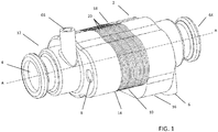
Figure 1 is an isometric view of a heat exchanger according to an example of the present disclosure; -
Figure 2 is an isometric view of the interior of the heat exchanger ofFigure 1 ; -
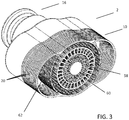
Figure 3 is an isometric view of a cross section through the main body of the heat exchanger ofFigure 1 ; -
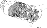
Figure 4 is exploded similar view toFigure 3 but showing some of the plates of the heat exchanger matrix in exploded view; -
Figure 5a is a top plan view of a single plate of the heat exchanger ofFigure 1 ; -
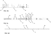
Figure 5b is a section along line H-H ofFigure 5a ; -
Figure 5c is a section along line J-J ofFigure 5a ; -
Figure 5d is a section along line K-K ofFigure 5a ; -
Figure 6a is a side view of the heat exchanger ofFigures 1 to 4 ; -
Figure 6b is a section along line A-A ofFigure 6a ; and -
Figure 6c is a section along line B-B ofFigure 6a . -
Figure 1 is an isometric view of aheat exchanger 2 according to an example of the present disclosure. As can be seen, theheat exchanger 2 is a three way heat exchanger, having a first inlet 4 for receiving a first fluid, asecond inlet 6 for receiving a second fluid, and athird inlet 8 for receiving a third fluid. Theheat exchanger 2 is configured to exchange heat between separate flows of the first and second fluids and between separate flows of the second and third fluids. - The
heat exchanger 2 comprises amain body 10 extending about a central longitudinal axis A-A. Themain body 10 is made up of a number ofplates 20 as will be described in further detail below. Afirst tank 12 extends about the axis A-A away from themain body 10 in a first direction and is provided adjacent to a firstlongitudinal end 14 of themain body 10. Asecond tank 16 extends about the axis A-A away from themain body 10 in a second direction, opposite to the first direction, and is provided adjacent to the secondlongitudinal end 18 of themain body 10. The first andsecond tanks tanks main body 10 of theheat exchanger 2 by brazing or welding. - As can be seen in
Figure 1 and shown in greater detail infigure 3 , themain body 10 of theheat exchanger 2 according to examples of the present disclosure comprises a matrix made up ofindividual plates 20. In one example, theplates 20 can be made from aluminium. In alternative examples, the plates may be made from other metals such as for example, copper, stainless steel or nickel alloy. The plates can be formed by an etching process (such as for example, acid etching, photo etching, laser etching or spark etching) by which portions of the plate are removed. Alternatively, the plates can be formed by being built up by 3D printing or by powder metallurgy. - As can be seen more clearly in
figures 4 and5a , the shape of eachplate 20 in top plan view comprises a solidcentral portion 22 which is circular in the example shown and has a thickness t (as seen inFigures 5b to 5d ). Spokes orfins 24 extend radially outwardly from thecircular portion 22 at regular intervals about theperimeter 21 thereof such that gaps or open areas 23 (forming a first flow passage 58) are left between thefins 24. In the example shown, 18radial fins 24 are evenly distributed about theperimeter 21 of thecircular portion 22. In the example shown, theradial fins 24 are not straight but rather take an undulating form, eachfin 24 forming a wave having a single trough and a single peak. The number and shape of the fins can be varied depending on the heat exchange requirements of a particular application. In one example according to the present disclosure, theradial fins 24 are formed to extend over the full thickness (t) of theplate 20. It would however be possible for them to extend only over a part of the thickness t of theplate 20, for example having a thickness of t/2 and extending from the base orsecond surface 19 of theplate 20 towards thefirst surface 25 thereof. - At their radially outer ends, the
fins 24 join with a firstannular ring 26 which is concentric with thecircular portion 22. A secondannular ring 28 extends concentrically with and radially outwardly from the firstannular ring 26 so as to form an annular gap 27 (forming a second flow passage 60) between the first and second annular rings 26, 28. The first and second annular rings 26, 28 are formed to extend over the full thickness t of theplate 20, having a thickness t in the example shown. Straight radial spokes orfins 30 extend between the first and second annular rings 26, 28. In the example shown, thirty straightradial fins 30 are evenly distributed about theperimeter 29 of the firstannular ring 26 and extend from thesecond surface 19 of theplate 20 over the full thickness t thereof, having a thickness of t. Two further concentric annular rings 31, 33 extend over a part of the thickness of the plate, one inside the other in thegap 27 between the first and second annular rings 26, 28. In the example shown, the further concentric annular rings 31, 33 have a thickness of t/2 and extend from thesecond surface 19 of theplate 20. - A third annular ring or
wall 32 is concentric with and spaced radially outwardly from the secondannular ring 28 so as to form an annular gap or gap 35 (which forms part of a third flow passage 62) between the second and thirdannular rings annular ring 32 is formed to extend over the full thickness t of theplate 20, having a thickness t in the example shown. A further set of straight radial spokes orfins 34 extends between the second and thirdannular rings radial fins 34 are evenly distributed about theperimeter 37 of the secondannular ring 28. - A first substantially semi-circular rim or
wall 36 is provided extending outwardly from afirst side 38 of the thirdannular ring 32 and having a radius (not shown) which is less than the radius (not shown) of the thirdannular ring 32. Thus, as seen in the plan view offigure 5 , afirst end 40 of the first substantiallysemi-circular rim 36 joins the radiallyouter edge 42 of the thirdannular ring 32 on a radius (not shown) at approximately 30° from the vertical in a clockwise direction, or approximately 1/12th of the distance around the radiallyouter edge 42 of the thirdannular ring 32. Thesecond end 44 of the first substantiallysemi-circular rim 36 joins the radiallyouter edge 42 of the thirdannular ring 32 on a radius (not shown) at approximately 150° from the vertical, or approximately 5/12th of the distance around the perimeter of the thirdannular ring 32. Thus the first substantiallysemi-circular rim 36 forms a firstouter portion 63 of thethird flow passage 62. - A second substantially semi-circular rim or
wall 46 extends outwardly from the thirdannular ring 32 on asecond side 48 thereof, opposite to thefirst side 38. The radius (not shown) of the second substantiallysemi-circular rim 46 is equal to the radius (not shown) of the first substantiallysemi-circular rim 36. As seen in the plan view offigure 5 , afirst end 50 of the first substantiallysemi-circular rim 36 joins the radiallyouter edge 42 of the thirdannular ring 32 on a radius (not shown) at approximately 330° from the vertical in the clockwise direction, or approximately 11/12th of the distance around the radiallyouter edge 42 of the thirdannular ring 32. Thesecond end 52 of the first substantiallysemi-circular rim 36 joins the radiallyouter edge 42 of the thirdannular ring 32 on a radius (not shown) at approximately 210° from the vertical, or approximately 7/12th of the distance around the perimeter of the thirdannular ring 32. Thus the second substantiallysemi-circular rim 46 forms a secondouter portion 65 of thethird flow passage 62. - In the example shown, the first and second substantially
semi-circular rims plate 20, having a thickness t. Theportions 47 of the thirdannular ring 32 which are not surrounded by the first and second substantiallysemi-circular rims plate 20, having a thickness t. Theportions 49 of the thirdannular ring 32 which are internal of one of the first and second substantiallysemi-circular rims semi-circular rim 36 or between the first and second ends 50, 52 of the second substantiallysemi-circular rim 46, extend over a distance d3 which is only part of the thickness t of theplate 20 from thesecond surface 19 thereof, having a thickness of t/2 in the example shown. - In preferred examples, each
plate 20 may have a thickness t of from about 0.5mm to 5mm. In the preferred example shown inFigures 3 to 5 , the plate has a thickness of 0.5mm. As described above, the thickness of thefins fins Figure 5 , pins 54, 56 which can be cylindrical in shape are provided on the further set of straightradial fins 34 extending perpendicular thereto and parallel to the longitudinal axis A of theheat exchanger 2. The height and shape of thepins pins plate 20. Thepins fins circular portion 22 and the annular rings 26, 28, 32. - In an alternative preferred example (not shown) some
pins plates 20 are joined together, fluid will be able to flow over theends 57 of thesepins stacked plates 20, thus further increasing turbulence in the fluid flow and potentially further improving the heat exchange capacity of theheat exchanger 2. - As seen in
Figure 5c , theradial fins 34 have afirst surface 39 which extends parallel to thefirst surface 25 of the plate, and asecond surface 41 which is integral with and in the plane of thesecond surface 19 of theplate 20.Figures 6b and 6c are sections through aplate 20,figure 6b being a section at a height of greater than t/2 from thesecond surface 19 of theplate 20, andfigure 6c being a section at a height of less than t/2 from thesecond surface 19 of theplate 20. As shown more clearly inFigures 6b to 6c , in the preferred example described here, two evenly distributed pins 54 are provided on eachradial fin 34, thepins 54 being evenly spaced on eachfin 34 between the second and thirdannular rings third pin 56 is provided at each intersection between aradial fin 34 and the shallower portions of the thirdannular ring 28, i.e. the portions of the thirdannular ring 28 having a thickness of t/2 in the example described. - As seen in
Figure 5c , in the preferred example shown, a first distance d1 from thesecond surfaces 41 of thefins 34 to anend 57 of thepins fins 34 is equal to a second distance d2 from thesecond surface 19 of theplate 20 to thefirst surface 25 thereof. - As seen in the drawings, the
main body 10 of theheat exchanger 2 is formed of a matrix of theplates 20 stacked adjacent to one another on the longitudinal axis A-A and joined together by brazing. When joined together, the plates form the first 58, second 60 and third 62 fluid flow passages of the heat exchangermain body 10. The firstfluid flow passage 58 is split into sections formed between the centralcircular portions 22, the firstannular rings 26 and theradial fins 24 of the joined togetherplates 20. (As each of these elements has a thickness of t, longitudinally adjacent elements will be in contact with one another when theplates 20 are stacked together in use and so will be joined together by the brazing process). Thus, for example, after brazing, the firstannular rings 26 of thestacked plates 20 will form a continuous cylindrical wall. - The second
fluid flow passage 60 is formed between the firstannular rings 26 and the second annular rings 28 of the joined togetherplates 20. (As each of these elements has a thickness of t, longitudinally adjacent elements will again be in contact with one another when theplates 20 are stacked together in use and so will be joined together by the brazing process). - The third
fluid flow passage 62 is formed between the second annular rings 28, the thirdannular rings 32 and the first and second substantiallysemi-circular rims plates 20. It will be understood that those parts of the thirdannular rings 32 having a thickness of t/2 will provide gaps through which fluid may flow when theplates 20 are assembled. Longitudinally adjacent second annular rings 28, those parts of the third annular rings having a thickness of t and the first and second substantiallysemi-circular rims fluid flow passage 62. - It will be understood from the above that by joining adjacent surfaces of elements of the
stacked plates 20 together by hard brazing, a fluid tight seal between the surfaces thereof may be achieved so as to provide fluid tight flow passages within the heat exchangermain body 10. - It will further be understood that the
first flow passage 58 is internal of thesecond flow passage 60 and is separated therefrom by the first annular rings 26 (or a dividing wall having a desired shape in alternative examples). Thesecond flow passage 60 is internal of thethird flow passage 62 and is separated therefrom by the second annular rings 28 (or a dividing wall having a desired shape in alternative examples). Thus, thesecond flow passage 60 extends around thefirst flow passage 58 and thethird flow passage 62 extends around thesecond flow passage 60. - In use, a first fluid flows from the first inlet 4 in the
first tank 12 into the firstfluid flow passage 58 in a first direction parallel to the longitudinal axis AA of theheat exchanger 2 to afirst outlet 64 in thesecond tank 16. The second fluid flows from thesecond inlet 6 in thesecond tank 16 into the secondfluid flow passage 60. It will be understood from the description above that the secondfluid flow passage 60 extends around and parallel to the firstfluid flow passage 58. The second fluid flows through thesecond flow passage 60 in a direction opposite to the direction of flow of the first fluid to reach a second outlet 66.The provision of opposite flow directions in the first and secondfluid flow passages heat exchanger 2. - The third fluid flows from the
third inlet 8 provided in thefirst tank 12, in the first direction parallel to the longitudinal axis AA of theheat exchanger 2, into the thirdfluid flow passage 62 on the side of the firstsemi-circular rim 36. It will be understood that the third fluid can flow from the area inside the firstsemi-circular rim 36 into the area between the third and second annular rings 32, 28 through gaps between the adjacent portions of the thirdannular rings 32 having a thickness of t/2. The third fluid will then flow around the second annular rings 28 to exit into the area inside the secondsemi-circular rims 40 by passing through gaps between the adjacent portions of the thirdannular rings 32 having a thickness of t/2. The third fluid will then flow in the second direction opposite to the first direction through the passage formed internally of the secondsemi-circular rims 40 to exit via a third outlet (not shown) provided in thefirst tank 12. - It will be understood that in use, heat will be exchanged between the first and second fluid flows via the dividing wall formed by the joined together first
annular rings 26 of thestacked plates 20. Theradial fins 24 will act to increase the secondary surface area for heat exchange. Further, in the preferred example shown, the undulating or twisted form thereof will act to produce a turbulent flow in the firstfluid flow passage 58, thus increasing heat exchange capacity. - It will be understood that pressure relief valves (not shown) may be provided at the fluid inlets and / or outlets as required.
- It will be appreciated that the walls of the
heat exchanger 2 in the example shown have curved edges. Further, every join between surfaces in each plate 20 (for example, between a fin and an annular ring) may be rounded. This results in improved strength and durability due to reduction in crack propagation risk. - To form the
heat exchanger 2, a desired number ofplates 20 of for example from 6 to 120 plates, or more preferably from 10 to 40 plates, are stacked on top of one another so as to be axially aligned and are joined together by being hard brazed and compressed together at a high temperature. In one preferred example as shown, theheat exchanger 2 may comprise 20 plates. During production, means such as visual sensors (not shown) may be used to verify the placement and correct order of the plates prior to brazing them together. In one preferred example, the visual sensors may comprise rectangular or semi-circular shapes etched into the radially outer surface of the thirdannular rings 32 of theplates 20. During assembly on a jig, the visual sensors may be used to correctly align theplates 20 as they are stacked, for example by forming a V from the aligned rectangular shapes. They also allow for the number of plates on the jig to be counted more easily than would otherwise be possible. It will be understood that any other suitable method of joining the plates together could also be used such as for example, diffusion bonding or welding. - When joined together, the
plates 20 form the heat exchangermain body 10 as described above. The use ofplates 20 joined together, for example by brazing, provides good sealing between the first, second andthird flow passages - In one example of use of a heat exchanger according to the present disclosure, cold oil may be inserted into the
second flow passage 60 to be heated by hot air from a turbine stage of an aircraft engine, the hot air flowing through thefirst flow passage 58. Cold air may be passed through thethird flow passage 62 to be heated and used for warming the edge of an aircraft wing. Alternatively, fuel to be heated before being combusted in a turbine engine can be passed through thethird flow passage 62. - An advantage of the heat exchanger of the present invention is that the direction of heat exchange between the fluids in the
heat exchanger 2 can be altered during the working cycle of theheat exchanger 2. It will be understood that the direction of heat exchange will depend on the relative heat or energy of each fluid in theheat exchanger 2. This will be affected by the inlet temperature of each fluid, the volumetric flow of each fluid, the temperature difference between each of the fluids and the thermal conductivity of each fluid. If the fluid in thesecond flow passage 60 has a higher energy level than the other two fluids, it will act to heat the fluids in both the first 58 and third 62 flow passages. If the fluid in thesecond flow passage 60 has a lower energy level than the other two fluids, it will be heated by the fluids in both the first 58 and third 62 flow passages. If the fluid in thesecond flow passage 60 has an energy level between that of the other two fluids, it will act to heat the fluid in one of the first 58 and third 62 flow passages and to cool the fluid in the other of the first 58 and third 62 flow passages. - The possibility of varying the direction of heat exchange could be useful for example in aerospace applications for gas turbine engines. For example, hot bleed air could be provided to the
first flow passage 58. Generator oil could be provided to thesecond passage 60 and fuel requiring to be heated prior to combustion in the gas turbine engine could be provided to thethird flow passage 62. When the engine first starts operating, it is necessary to heat the generator oil to reduce the resistance of the main engine rotor. After this however, the generator oil is required to be cooled. By varying the rate of flow of fuel in thethird flow passage 62 it is possible to achieve the required effect of initially heating the generator oil but then cooling it after a predetermined time has elapsed. - It will be understood that when used in an engine, the space available for a heat exchanger may be limited and may also be an irregular shape. The heat exchanger according to the present disclosure allows a shape to be created which can be fitted to the available space, for example by varying the shape of successive plates stacked in the heat exchanger matrix. For example therefore, the heat exchanger could be designed to take a banana-type shape to fit with an engine nacelle and also to be circular in cross section.
- A further advantage of the heat exchanger of the present disclosure is that the drop in pressure of the first, second and/or third fluids in use may be relatively low compared to know heat exchangers. This is because the drop in pressure will be a function of the possible flow area (i.e. the area in which flow is not blocked) and the length of the heat exchanger. The structure of the heat exchanger of the present disclosure provides a greater possible flow area than would be provided for example in a heat exchanger using known plate fin technology in which flow is often blocked by corrugations.
- It will be appreciated by those skilled in the art that the present disclosure has been illustrated by describing one or more specific examples thereof, but is not limited to these examples; many variations and modifications are possible, within the scope of the accompanying claims.
- For example, although the structure described above includes three fluid flow passages, it will be understood that the structure could be modified to include four or more fluid flow passages to allow for heat exchange between four or more separate fluid flows. Further, the shape and number of the various flow passages and of the fins and pins within the various flow passages could be varied as required.
Claims (15)
- A plate (20) for use in a heat exchanger (2), the plate (20) comprising:a first surface (25);a second surface (19) extending parallel to and spaced from the first surface (25);first, second and third discrete flow passages (58, 60, 62) passing through the plate (20) from the first surface (25) to the second surface (19),the second flow passage (60) extending around the first flow passage (58) and the third flow passage (62) extending around the second flow passage (60);a plurality of fins (34) extending parallel to the first surface (25) across the third flow passage (62) and having a first fin surface (39) extending parallel to the first surface (25) of the plate (20) and a second fin surface (41) extending parallel to and spaced from the first fin surface (39); andone or more pins (54, 56) protruding from the first fin surface (39) of at least some of the fins (34), the pins (54, 56) extending away from the second fin surfaces (41),wherein a first distance (d1) from the second fin surfaces (41) to an end (57) of the pins (54, 56) removed from the first fin surfaces (39) is less than or equal to a second distance d2 from the second surface (19) of the plate (20) to the first surface (25) thereof.
- A plate (20) as claimed in claim 1, further comprising a solid central portion (22) extending from the first surface (25) to the second surface (19),
wherein the first flow passage (58) extends around the solid central portion (22). - A plate (20) as claimed in claim 2, further comprising a plurality of second fins (24) extending across the first flow passage (58) from the solid central portion (22) towards the second flow passage (60).
- A plate (20) as claimed in claim 3, wherein the second fins (24) have an undulating form.
- A plate (20) as claimed in any preceding claim, wherein the pins (54, 56) are twisted in a direction perpendicular to the direction of the flow of fluid through the third flow passage (62) in use.
- A plate (20) as claimed in any preceding claim, the third flow passage (62) comprising a gap (35) formed by a wall (32) extending outwardly of and around the second flow passage (60), and first and second outer portions (63, 65) formed by walls (36, 46) extending outwardly from the wall (32) and re-joining therewith on either side thereof, wherein the sections of the wall (32) which are internal of the first and second outer portions (63, 65) extend over a third distance (d3) which is less than the second distance (d2) from the first surface to the second surface of the plate, and the other sections of the wall and the walls (36, 46) extending outwardly from the wall (32) on either side thereof extend from the first surface (25) to the second surface (19) of the plate (20).
- A plate (20) as claimed in any preceding claim, wherein the plate (20) is formed by etching, additive manufacturing, 3D printing or powder metallurgy.
- A heat exchanger body (10) comprising a number of plates (20) as claimed in any preceding claim, wherein the plates (20) are arranged adjacent to one another along a longitudinal axis (A-A) of the heat exchanger body (10) such that the first surface (25) of a first plate (20) is in contact with the second surface (19) of an adjacent plate (20), and
the first, second and third flow passages (58, 60, 62) of adjacent plates (20) are joined together to form continuous first, second and third flow passages (58, 60, 62) extending through the heat exchanger body (10). - A heat exchanger body (10) as claimed in claim 8, further comprising:a first inlet (4) to the first flow passage (58) provided at a first longitudinal end (14) of the heat exchanger body (10) and a first outlet (64) from the first flow passage (58) provided at a second longitudinal end (18) of the heat exchanger body (10); anda second inlet (6) to the second flow passage (60) provided at the second longitudinal end (18) of the heat exchanger body (10) and a second outlet (66) from the second flow passage (60) provided at the first longitudinal end (14) of the heat exchanger body (10) such that in use, fluid will flow through the second flow passage (60) in a direction opposite to the direction of flow of fluid through the first flow passage (58).
- A heat exchanger body (10) as claimed in claim 9, further comprising:a third inlet (8) to the third flow passage (62) provided at the first longitudinal end (14) of the heat exchanger body (10) and a third outlet from the third flow passage (62) provided at the first longitudinal end (14) of the heat exchanger body (10).
- A heat exchanger body (10) as claimed in claim 11, wherein the third inlet (8) is provided on a first side of the heat exchanger body (10) and the third outlet is provided on a second opposite side of the heat exchanger body (10) such that in use, fluid will flow through the third flow passage (62) in the first longitudinal direction on the first side of the heat exchanger body (10), flow around the second passage (60) in a direction perpendicular to the first longitudinal direction and then flow to the third outlet in the second longitudinal direction on the second side of the heat exchanger body (10).
- A method of exchanging heat between fluid flows, the method comprising:passing a first fluid flow in a first direction through a first flow passage (58) extending through a plurality of plates (20) in a heat exchanger body (10);passing a second fluid flow in a second direction opposite to the first direction through a second flow passage (60) extending around the first flow passage (58) through the plurality of plates (20) in the heat exchanger body (10); andpassing a third fluid flow through a third flow passage (62) extending around the second flow passage (60) through the plurality of plates (20) in the heat exchanger body (10).
- A method of manufacturing a heat exchanger (2), the method comprising:forming a plurality of plates (20) as claimed in any of claims 1 to 7; andstacking the plurality of plates (20) one above the other in a desired configuration so as to align the first, second and third flow passages (58, 60, 62) in the plurality of plates (20).
- A method of manufacturing a heat exchanger (2) as claimed in claim 13, further comprising:joining the plates (20) together by brazing.
- A method as claimed in claim 14, wherein the plurality of plates (20) vary in shape and are stacked so as to form a heat exchanger body (10) having an irregular shape.
Priority Applications (2)
| Application Number | Priority Date | Filing Date | Title |
|---|---|---|---|
| EP18461513.6A EP3521742B1 (en) | 2018-02-01 | 2018-02-01 | Heat exchanger |
| US16/246,607 US10866030B2 (en) | 2018-02-01 | 2019-01-14 | Heat exchanger |
Applications Claiming Priority (1)
| Application Number | Priority Date | Filing Date | Title |
|---|---|---|---|
| EP18461513.6A EP3521742B1 (en) | 2018-02-01 | 2018-02-01 | Heat exchanger |
Publications (2)
| Publication Number | Publication Date |
|---|---|
| EP3521742A1 true EP3521742A1 (en) | 2019-08-07 |
| EP3521742B1 EP3521742B1 (en) | 2020-07-22 |
Family
ID=61157145
Family Applications (1)
| Application Number | Title | Priority Date | Filing Date |
|---|---|---|---|
| EP18461513.6A Active EP3521742B1 (en) | 2018-02-01 | 2018-02-01 | Heat exchanger |
Country Status (2)
| Country | Link |
|---|---|
| US (1) | US10866030B2 (en) |
| EP (1) | EP3521742B1 (en) |
Cited By (1)
| Publication number | Priority date | Publication date | Assignee | Title |
|---|---|---|---|---|
| FR3119670A1 (en) * | 2021-02-09 | 2022-08-12 | Safran | Heat exchanger and its manufacturing method |
Families Citing this family (15)
| Publication number | Priority date | Publication date | Assignee | Title |
|---|---|---|---|---|
| US11293703B2 (en) | 2016-01-12 | 2022-04-05 | Hamilton Sundstrand Corporation | Heat exchangers |
| US10088250B2 (en) | 2016-01-12 | 2018-10-02 | Hamilton Sundstrand Corporation | Heat exchangers |
| US12140077B2 (en) | 2020-01-03 | 2024-11-12 | Rtx Corporation | Aircraft heat exchanger assembly |
| US12297775B2 (en) | 2020-01-03 | 2025-05-13 | Rtx Corporation | Aircraft heat exchanger panel array interconnection |
| US11448132B2 (en) | 2020-01-03 | 2022-09-20 | Raytheon Technologies Corporation | Aircraft bypass duct heat exchanger |
| US11525637B2 (en) | 2020-01-19 | 2022-12-13 | Raytheon Technologies Corporation | Aircraft heat exchanger finned plate manufacture |
| EP3911908B1 (en) | 2020-01-19 | 2023-07-12 | Raytheon Technologies Corporation | Aircraft heat exchanger |
| US11674758B2 (en) | 2020-01-19 | 2023-06-13 | Raytheon Technologies Corporation | Aircraft heat exchangers and plates |
| US11585273B2 (en) | 2020-01-20 | 2023-02-21 | Raytheon Technologies Corporation | Aircraft heat exchangers |
| US11585605B2 (en) | 2020-02-07 | 2023-02-21 | Raytheon Technologies Corporation | Aircraft heat exchanger panel attachment |
| CN111238270B (en) * | 2020-03-18 | 2025-05-27 | 无锡市冠云换热器有限公司 | Surrounding heat exchanger |
| FR3137753B1 (en) * | 2022-07-08 | 2024-08-16 | Safran | VARIABLE HEIGHT FIN HEAT EXCHANGER AND CORRESPONDING TURBOMACHINE |
| FR3137754B1 (en) * | 2022-07-08 | 2024-07-05 | Safran | FINNED HEAT EXCHANGER OF VARIABLE LENGTH AND CORRESPONDING TURBOMACHINE |
| CN117346561B (en) * | 2023-09-12 | 2024-04-19 | 贵州永红航空机械有限责任公司 | A high-efficiency annular radiator and heat exchange method |
| CN117685804B (en) * | 2024-02-04 | 2024-04-30 | 西安交通大学 | Multi-header split-flow annular printed circuit board heat exchanger |
Citations (5)
| Publication number | Priority date | Publication date | Assignee | Title |
|---|---|---|---|---|
| US4096616A (en) * | 1976-10-28 | 1978-06-27 | General Electric Company | Method of manufacturing a concentric tube heat exchanger |
| US20090145581A1 (en) * | 2007-12-11 | 2009-06-11 | Paul Hoffman | Non-linear fin heat sink |
| EP2924385A1 (en) * | 2013-11-14 | 2015-09-30 | Sumitomo Precision Products Co., Ltd. | Heat exchanger for aircraft |
| EP3026384A2 (en) * | 2014-11-10 | 2016-06-01 | Rolls-Royce plc | Heat exchanger |
| EP3249334A1 (en) * | 2016-05-23 | 2017-11-29 | Hamilton Sundstrand Corporation | Multiple flow heat exchanger |
Family Cites Families (8)
| Publication number | Priority date | Publication date | Assignee | Title |
|---|---|---|---|---|
| CH350746A (en) | 1956-07-20 | 1960-12-15 | Ciba Geigy | Process for the production of color pigments in an easily spreadable form |
| EP1086349B1 (en) | 1998-06-12 | 2003-07-23 | Chart Heat Exchangers Limited | Heat exchanger |
| EP1166026B1 (en) | 1999-03-27 | 2006-12-20 | CHART HEAT EXCHANGERS Limited Partnership | Heat exchanger |
| GB0220652D0 (en) | 2002-09-05 | 2002-10-16 | Chart Heat Exchangers Ltd | Heat exchanger |
| DE10243522A1 (en) * | 2002-09-19 | 2004-04-01 | Modine Manufacturing Co., Racine | Plate heat exchangers |
| WO2012145262A1 (en) * | 2011-04-19 | 2012-10-26 | Modine Manufacturing Company | Heat exchanger |
| US10012107B2 (en) | 2011-05-11 | 2018-07-03 | Dresser-Rand Company | Compact compression system with integral heat exchangers |
| US20130042612A1 (en) * | 2011-08-15 | 2013-02-21 | Laurence Jay Shapiro | Ocean thermal energy conversion power plant |
-
2018
- 2018-02-01 EP EP18461513.6A patent/EP3521742B1/en active Active
-
2019
- 2019-01-14 US US16/246,607 patent/US10866030B2/en active Active
Patent Citations (5)
| Publication number | Priority date | Publication date | Assignee | Title |
|---|---|---|---|---|
| US4096616A (en) * | 1976-10-28 | 1978-06-27 | General Electric Company | Method of manufacturing a concentric tube heat exchanger |
| US20090145581A1 (en) * | 2007-12-11 | 2009-06-11 | Paul Hoffman | Non-linear fin heat sink |
| EP2924385A1 (en) * | 2013-11-14 | 2015-09-30 | Sumitomo Precision Products Co., Ltd. | Heat exchanger for aircraft |
| EP3026384A2 (en) * | 2014-11-10 | 2016-06-01 | Rolls-Royce plc | Heat exchanger |
| EP3249334A1 (en) * | 2016-05-23 | 2017-11-29 | Hamilton Sundstrand Corporation | Multiple flow heat exchanger |
Cited By (1)
| Publication number | Priority date | Publication date | Assignee | Title |
|---|---|---|---|---|
| FR3119670A1 (en) * | 2021-02-09 | 2022-08-12 | Safran | Heat exchanger and its manufacturing method |
Also Published As
| Publication number | Publication date |
|---|---|
| US10866030B2 (en) | 2020-12-15 |
| EP3521742B1 (en) | 2020-07-22 |
| US20190234690A1 (en) | 2019-08-01 |
Similar Documents
| Publication | Publication Date | Title |
|---|---|---|
| US10866030B2 (en) | Heat exchanger | |
| JP6367869B2 (en) | Counterflow heat exchanger with spiral passage | |
| US7303002B2 (en) | Fin structure, heat-transfer tube having the fin structure housed therein, and heat exchanger having the heat-transfer tube assembled therein | |
| EP0077656B1 (en) | Plate-type heat exchanger | |
| US4742866A (en) | Heat exchanger | |
| EP1834153B1 (en) | Heat exchanger | |
| US8235098B2 (en) | Heat exchanger flat tube with oblique elongate dimples | |
| CN205607209U (en) | Heat exchanger | |
| JP2015155792A (en) | Heat exchanger and method of making and using it | |
| EP2942593B1 (en) | Multi-plate-stack-type heat exchanger, and core plate therefor | |
| US4917181A (en) | Segmented annular recuperator and method | |
| EP3695185B1 (en) | A heat exchanger and an additive manufacturing method for manufacturing a heat exchanger | |
| US8944155B2 (en) | Annular axial flow ribbed heat exchanger | |
| KR101414309B1 (en) | Heat exchanger fins, assemblies and methods | |
| US20070000652A1 (en) | Heat exchanger with dimpled tube surfaces | |
| EP3396296B1 (en) | Heat exchanger assembly | |
| CN212658118U (en) | Fin heat exchanger | |
| EP3855103B1 (en) | Helical fractal heat exchanger | |
| RU2659677C1 (en) | Plate heat exchanger and the plate heat exchanger manufacturing method | |
| KR102010156B1 (en) | shell in a shell and plate heat exchanger, and shell and plate heat exchanger having the same | |
| US11112191B2 (en) | Heat exchanger with turbulating inserts | |
| EP2064509B1 (en) | Heat transfer surfaces with flanged apertures | |
| EP3742100B1 (en) | Plate heat exchanger | |
| EP3236188B1 (en) | Heat exchangers | |
| CN218821865U (en) | Plate heat exchanger plates, plate heat exchangers and electric vehicles |
Legal Events
| Date | Code | Title | Description |
|---|---|---|---|
| PUAI | Public reference made under article 153(3) epc to a published international application that has entered the european phase |
Free format text: ORIGINAL CODE: 0009012 |
|
| STAA | Information on the status of an ep patent application or granted ep patent |
Free format text: STATUS: THE APPLICATION HAS BEEN PUBLISHED |
|
| AK | Designated contracting states |
Kind code of ref document: A1 Designated state(s): AL AT BE BG CH CY CZ DE DK EE ES FI FR GB GR HR HU IE IS IT LI LT LU LV MC MK MT NL NO PL PT RO RS SE SI SK SM TR |
|
| AX | Request for extension of the european patent |
Extension state: BA ME |
|
| STAA | Information on the status of an ep patent application or granted ep patent |
Free format text: STATUS: REQUEST FOR EXAMINATION WAS MADE |
|
| 17P | Request for examination filed |
Effective date: 20191119 |
|
| RBV | Designated contracting states (corrected) |
Designated state(s): AL AT BE BG CH CY CZ DE DK EE ES FI FR GB GR HR HU IE IS IT LI LT LU LV MC MK MT NL NO PL PT RO RS SE SI SK SM TR |
|
| GRAP | Despatch of communication of intention to grant a patent |
Free format text: ORIGINAL CODE: EPIDOSNIGR1 |
|
| STAA | Information on the status of an ep patent application or granted ep patent |
Free format text: STATUS: GRANT OF PATENT IS INTENDED |
|
| RIC1 | Information provided on ipc code assigned before grant |
Ipc: F28D 21/00 20060101ALI20191204BHEP Ipc: F28D 9/00 20060101AFI20191204BHEP Ipc: F28D 7/10 20060101ALI20191204BHEP |
|
| INTG | Intention to grant announced |
Effective date: 20200102 |
|
| GRAS | Grant fee paid |
Free format text: ORIGINAL CODE: EPIDOSNIGR3 |
|
| GRAA | (expected) grant |
Free format text: ORIGINAL CODE: 0009210 |
|
| STAA | Information on the status of an ep patent application or granted ep patent |
Free format text: STATUS: THE PATENT HAS BEEN GRANTED |
|
| AK | Designated contracting states |
Kind code of ref document: B1 Designated state(s): AL AT BE BG CH CY CZ DE DK EE ES FI FR GB GR HR HU IE IS IT LI LT LU LV MC MK MT NL NO PL PT RO RS SE SI SK SM TR |
|
| REG | Reference to a national code |
Ref country code: GB Ref legal event code: FG4D |
|
| REG | Reference to a national code |
Ref country code: CH Ref legal event code: EP |
|
| REG | Reference to a national code |
Ref country code: DE Ref legal event code: R096 Ref document number: 602018006269 Country of ref document: DE |
|
| REG | Reference to a national code |
Ref country code: AT Ref legal event code: REF Ref document number: 1293798 Country of ref document: AT Kind code of ref document: T Effective date: 20200815 |
|
| REG | Reference to a national code |
Ref country code: IE Ref legal event code: FG4D |
|
| REG | Reference to a national code |
Ref country code: LT Ref legal event code: MG4D |
|
| REG | Reference to a national code |
Ref country code: AT Ref legal event code: MK05 Ref document number: 1293798 Country of ref document: AT Kind code of ref document: T Effective date: 20200722 |
|
| PG25 | Lapsed in a contracting state [announced via postgrant information from national office to epo] |
Ref country code: SE Free format text: LAPSE BECAUSE OF FAILURE TO SUBMIT A TRANSLATION OF THE DESCRIPTION OR TO PAY THE FEE WITHIN THE PRESCRIBED TIME-LIMIT Effective date: 20200722 Ref country code: GR Free format text: LAPSE BECAUSE OF FAILURE TO SUBMIT A TRANSLATION OF THE DESCRIPTION OR TO PAY THE FEE WITHIN THE PRESCRIBED TIME-LIMIT Effective date: 20201023 Ref country code: FI Free format text: LAPSE BECAUSE OF FAILURE TO SUBMIT A TRANSLATION OF THE DESCRIPTION OR TO PAY THE FEE WITHIN THE PRESCRIBED TIME-LIMIT Effective date: 20200722 Ref country code: PT Free format text: LAPSE BECAUSE OF FAILURE TO SUBMIT A TRANSLATION OF THE DESCRIPTION OR TO PAY THE FEE WITHIN THE PRESCRIBED TIME-LIMIT Effective date: 20201123 Ref country code: BG Free format text: LAPSE BECAUSE OF FAILURE TO SUBMIT A TRANSLATION OF THE DESCRIPTION OR TO PAY THE FEE WITHIN THE PRESCRIBED TIME-LIMIT Effective date: 20201022 Ref country code: ES Free format text: LAPSE BECAUSE OF FAILURE TO SUBMIT A TRANSLATION OF THE DESCRIPTION OR TO PAY THE FEE WITHIN THE PRESCRIBED TIME-LIMIT Effective date: 20200722 Ref country code: NO Free format text: LAPSE BECAUSE OF FAILURE TO SUBMIT A TRANSLATION OF THE DESCRIPTION OR TO PAY THE FEE WITHIN THE PRESCRIBED TIME-LIMIT Effective date: 20201022 Ref country code: AT Free format text: LAPSE BECAUSE OF FAILURE TO SUBMIT A TRANSLATION OF THE DESCRIPTION OR TO PAY THE FEE WITHIN THE PRESCRIBED TIME-LIMIT Effective date: 20200722 Ref country code: LT Free format text: LAPSE BECAUSE OF FAILURE TO SUBMIT A TRANSLATION OF THE DESCRIPTION OR TO PAY THE FEE WITHIN THE PRESCRIBED TIME-LIMIT Effective date: 20200722 Ref country code: HR Free format text: LAPSE BECAUSE OF FAILURE TO SUBMIT A TRANSLATION OF THE DESCRIPTION OR TO PAY THE FEE WITHIN THE PRESCRIBED TIME-LIMIT Effective date: 20200722 |
|
| PG25 | Lapsed in a contracting state [announced via postgrant information from national office to epo] |
Ref country code: IS Free format text: LAPSE BECAUSE OF FAILURE TO SUBMIT A TRANSLATION OF THE DESCRIPTION OR TO PAY THE FEE WITHIN THE PRESCRIBED TIME-LIMIT Effective date: 20201122 Ref country code: PL Free format text: LAPSE BECAUSE OF FAILURE TO SUBMIT A TRANSLATION OF THE DESCRIPTION OR TO PAY THE FEE WITHIN THE PRESCRIBED TIME-LIMIT Effective date: 20200722 Ref country code: RS Free format text: LAPSE BECAUSE OF FAILURE TO SUBMIT A TRANSLATION OF THE DESCRIPTION OR TO PAY THE FEE WITHIN THE PRESCRIBED TIME-LIMIT Effective date: 20200722 Ref country code: LV Free format text: LAPSE BECAUSE OF FAILURE TO SUBMIT A TRANSLATION OF THE DESCRIPTION OR TO PAY THE FEE WITHIN THE PRESCRIBED TIME-LIMIT Effective date: 20200722 |
|
| PG25 | Lapsed in a contracting state [announced via postgrant information from national office to epo] |
Ref country code: NL Free format text: LAPSE BECAUSE OF FAILURE TO SUBMIT A TRANSLATION OF THE DESCRIPTION OR TO PAY THE FEE WITHIN THE PRESCRIBED TIME-LIMIT Effective date: 20200722 |
|
| REG | Reference to a national code |
Ref country code: DE Ref legal event code: R097 Ref document number: 602018006269 Country of ref document: DE |
|
| PG25 | Lapsed in a contracting state [announced via postgrant information from national office to epo] |
Ref country code: EE Free format text: LAPSE BECAUSE OF FAILURE TO SUBMIT A TRANSLATION OF THE DESCRIPTION OR TO PAY THE FEE WITHIN THE PRESCRIBED TIME-LIMIT Effective date: 20200722 Ref country code: RO Free format text: LAPSE BECAUSE OF FAILURE TO SUBMIT A TRANSLATION OF THE DESCRIPTION OR TO PAY THE FEE WITHIN THE PRESCRIBED TIME-LIMIT Effective date: 20200722 Ref country code: DK Free format text: LAPSE BECAUSE OF FAILURE TO SUBMIT A TRANSLATION OF THE DESCRIPTION OR TO PAY THE FEE WITHIN THE PRESCRIBED TIME-LIMIT Effective date: 20200722 Ref country code: CZ Free format text: LAPSE BECAUSE OF FAILURE TO SUBMIT A TRANSLATION OF THE DESCRIPTION OR TO PAY THE FEE WITHIN THE PRESCRIBED TIME-LIMIT Effective date: 20200722 Ref country code: IT Free format text: LAPSE BECAUSE OF FAILURE TO SUBMIT A TRANSLATION OF THE DESCRIPTION OR TO PAY THE FEE WITHIN THE PRESCRIBED TIME-LIMIT Effective date: 20200722 Ref country code: SM Free format text: LAPSE BECAUSE OF FAILURE TO SUBMIT A TRANSLATION OF THE DESCRIPTION OR TO PAY THE FEE WITHIN THE PRESCRIBED TIME-LIMIT Effective date: 20200722 |
|
| PLBE | No opposition filed within time limit |
Free format text: ORIGINAL CODE: 0009261 |
|
| STAA | Information on the status of an ep patent application or granted ep patent |
Free format text: STATUS: NO OPPOSITION FILED WITHIN TIME LIMIT |
|
| PG25 | Lapsed in a contracting state [announced via postgrant information from national office to epo] |
Ref country code: AL Free format text: LAPSE BECAUSE OF FAILURE TO SUBMIT A TRANSLATION OF THE DESCRIPTION OR TO PAY THE FEE WITHIN THE PRESCRIBED TIME-LIMIT Effective date: 20200722 |
|
| 26N | No opposition filed |
Effective date: 20210423 |
|
| PG25 | Lapsed in a contracting state [announced via postgrant information from national office to epo] |
Ref country code: SK Free format text: LAPSE BECAUSE OF FAILURE TO SUBMIT A TRANSLATION OF THE DESCRIPTION OR TO PAY THE FEE WITHIN THE PRESCRIBED TIME-LIMIT Effective date: 20200722 |
|
| PG25 | Lapsed in a contracting state [announced via postgrant information from national office to epo] |
Ref country code: SI Free format text: LAPSE BECAUSE OF FAILURE TO SUBMIT A TRANSLATION OF THE DESCRIPTION OR TO PAY THE FEE WITHIN THE PRESCRIBED TIME-LIMIT Effective date: 20200722 |
|
| PG25 | Lapsed in a contracting state [announced via postgrant information from national office to epo] |
Ref country code: MC Free format text: LAPSE BECAUSE OF FAILURE TO SUBMIT A TRANSLATION OF THE DESCRIPTION OR TO PAY THE FEE WITHIN THE PRESCRIBED TIME-LIMIT Effective date: 20200722 |
|
| REG | Reference to a national code |
Ref country code: NL Ref legal event code: MP Effective date: 20200722 |
|
| REG | Reference to a national code |
Ref country code: BE Ref legal event code: MM Effective date: 20210228 |
|
| PG25 | Lapsed in a contracting state [announced via postgrant information from national office to epo] |
Ref country code: CH Free format text: LAPSE BECAUSE OF NON-PAYMENT OF DUE FEES Effective date: 20210228 Ref country code: LI Free format text: LAPSE BECAUSE OF NON-PAYMENT OF DUE FEES Effective date: 20210228 Ref country code: LU Free format text: LAPSE BECAUSE OF NON-PAYMENT OF DUE FEES Effective date: 20210201 |
|
| PG25 | Lapsed in a contracting state [announced via postgrant information from national office to epo] |
Ref country code: IE Free format text: LAPSE BECAUSE OF NON-PAYMENT OF DUE FEES Effective date: 20210201 |
|
| PG25 | Lapsed in a contracting state [announced via postgrant information from national office to epo] |
Ref country code: BE Free format text: LAPSE BECAUSE OF NON-PAYMENT OF DUE FEES Effective date: 20210228 |
|
| P01 | Opt-out of the competence of the unified patent court (upc) registered |
Effective date: 20230522 |
|
| PG25 | Lapsed in a contracting state [announced via postgrant information from national office to epo] |
Ref country code: CY Free format text: LAPSE BECAUSE OF FAILURE TO SUBMIT A TRANSLATION OF THE DESCRIPTION OR TO PAY THE FEE WITHIN THE PRESCRIBED TIME-LIMIT Effective date: 20200722 |
|
| PG25 | Lapsed in a contracting state [announced via postgrant information from national office to epo] |
Ref country code: HU Free format text: LAPSE BECAUSE OF FAILURE TO SUBMIT A TRANSLATION OF THE DESCRIPTION OR TO PAY THE FEE WITHIN THE PRESCRIBED TIME-LIMIT; INVALID AB INITIO Effective date: 20180201 |
|
| PG25 | Lapsed in a contracting state [announced via postgrant information from national office to epo] |
Ref country code: MK Free format text: LAPSE BECAUSE OF FAILURE TO SUBMIT A TRANSLATION OF THE DESCRIPTION OR TO PAY THE FEE WITHIN THE PRESCRIBED TIME-LIMIT Effective date: 20200722 |
|
| PG25 | Lapsed in a contracting state [announced via postgrant information from national office to epo] |
Ref country code: MT Free format text: LAPSE BECAUSE OF FAILURE TO SUBMIT A TRANSLATION OF THE DESCRIPTION OR TO PAY THE FEE WITHIN THE PRESCRIBED TIME-LIMIT Effective date: 20200722 |
|
| PG25 | Lapsed in a contracting state [announced via postgrant information from national office to epo] |
Ref country code: TR Free format text: LAPSE BECAUSE OF FAILURE TO SUBMIT A TRANSLATION OF THE DESCRIPTION OR TO PAY THE FEE WITHIN THE PRESCRIBED TIME-LIMIT Effective date: 20200722 |
|
| PGFP | Annual fee paid to national office [announced via postgrant information from national office to epo] |
Ref country code: GB Payment date: 20260121 Year of fee payment: 9 |
|
| PGFP | Annual fee paid to national office [announced via postgrant information from national office to epo] |
Ref country code: DE Payment date: 20260121 Year of fee payment: 9 |
|
| PGFP | Annual fee paid to national office [announced via postgrant information from national office to epo] |
Ref country code: FR Payment date: 20260121 Year of fee payment: 9 |