EP3521608B1 - High-pressure fuel supply pump - Google Patents
High-pressure fuel supply pump Download PDFInfo
- Publication number
- EP3521608B1 EP3521608B1 EP17855429.1A EP17855429A EP3521608B1 EP 3521608 B1 EP3521608 B1 EP 3521608B1 EP 17855429 A EP17855429 A EP 17855429A EP 3521608 B1 EP3521608 B1 EP 3521608B1
- Authority
- EP
- European Patent Office
- Prior art keywords
- fuel
- suction valve
- anchor
- pressure
- spring
- Prior art date
- Legal status (The legal status is an assumption and is not a legal conclusion. Google has not performed a legal analysis and makes no representation as to the accuracy of the status listed.)
- Active
Links
Images



Classifications
-
- F—MECHANICAL ENGINEERING; LIGHTING; HEATING; WEAPONS; BLASTING
- F02—COMBUSTION ENGINES; HOT-GAS OR COMBUSTION-PRODUCT ENGINE PLANTS
- F02M—SUPPLYING COMBUSTION ENGINES IN GENERAL WITH COMBUSTIBLE MIXTURES OR CONSTITUENTS THEREOF
- F02M59/00—Pumps specially adapted for fuel-injection and not provided for in groups F02M39/00 -F02M57/00, e.g. rotary cylinder-block type of pumps
- F02M59/20—Varying fuel delivery in quantity or timing
- F02M59/36—Varying fuel delivery in quantity or timing by variably-timed valves controlling fuel passages to pumping elements or overflow passages
- F02M59/366—Valves being actuated electrically
-
- F—MECHANICAL ENGINEERING; LIGHTING; HEATING; WEAPONS; BLASTING
- F02—COMBUSTION ENGINES; HOT-GAS OR COMBUSTION-PRODUCT ENGINE PLANTS
- F02M—SUPPLYING COMBUSTION ENGINES IN GENERAL WITH COMBUSTIBLE MIXTURES OR CONSTITUENTS THEREOF
- F02M59/00—Pumps specially adapted for fuel-injection and not provided for in groups F02M39/00 -F02M57/00, e.g. rotary cylinder-block type of pumps
- F02M59/20—Varying fuel delivery in quantity or timing
- F02M59/34—Varying fuel delivery in quantity or timing by throttling of passages to pumping elements or of overflow passages, e.g. throttling by means of a pressure-controlled sliding valve having liquid stop or abutment
-
- F—MECHANICAL ENGINEERING; LIGHTING; HEATING; WEAPONS; BLASTING
- F02—COMBUSTION ENGINES; HOT-GAS OR COMBUSTION-PRODUCT ENGINE PLANTS
- F02M—SUPPLYING COMBUSTION ENGINES IN GENERAL WITH COMBUSTIBLE MIXTURES OR CONSTITUENTS THEREOF
- F02M59/00—Pumps specially adapted for fuel-injection and not provided for in groups F02M39/00 -F02M57/00, e.g. rotary cylinder-block type of pumps
- F02M59/20—Varying fuel delivery in quantity or timing
- F02M59/36—Varying fuel delivery in quantity or timing by variably-timed valves controlling fuel passages to pumping elements or overflow passages
Definitions
- the present invention relates to a high-pressure fuel supply pump that pumps fuel to a fuel injection valve of an internal combustion engine, and particularly relates to a high-pressure fuel pump including an electromagnetic suction valve that adjusts an amount of fuel to be discharged.
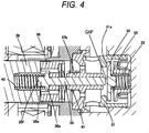
- FIG. 4 is an enlarged view of the electromagnetic suction valve 300 and illustrates a state in which: the electromagnetic coil 43 is energized and an anchor 36 provided as a movable part contacts a second core 39 by electromagnetic attraction force; and the suction valve 30 is closed.
- the fuel guided to the low-pressure fuel suction port 10a is pressurized to a high pressure by the reciprocating motion of the plunger 2 in the pressurizing chamber 11 of the pump main body 1 provided as the pump main body, and it is possible to provide the high-pressure pump suitable for pumping the fuel from the fuel discharge port 12 to the common rail 23.
- the high-pressure fuel supply pump having the above-described structure is characterized in that the fuel in the spring space 48 where the spring 40 is disposed is made to flow to the suction valve 30 side via the fuel path 36a and a fuel path 36f in the case where the anchor 36 is moved toward the second core 39. As a result, the fuel can be moved by operation of the anchor.
- FIG. 9 The fuel path inside the anchor 36 is illustrated in FIG. 9 , and magnetic attraction force is generated between the anchor 36 and the second core 39 by energizing the electromagnetic coil 43, and the fluid is pushed way by movement of the anchor 36 and the rod 35 toward the second core side, and flow toward the suction valve side through the combustion path 36a. At this point, a flow separation part is generated and the pressure drops due to influence of the flow after the fluid passes through the vicinity of the rod protrusion part 35a, and cavitation occurs.
Landscapes
- Engineering & Computer Science (AREA)
- Chemical & Material Sciences (AREA)
- Combustion & Propulsion (AREA)
- Mechanical Engineering (AREA)
- General Engineering & Computer Science (AREA)
- Fuel-Injection Apparatus (AREA)
Description
- The present invention relates to a high-pressure fuel supply pump that pumps fuel to a fuel injection valve of an internal combustion engine, and particularly relates to a high-pressure fuel pump including an electromagnetic suction valve that adjusts an amount of fuel to be discharged.
- There is a widely used high-pressure fuel supply pump including an electromagnetic suction valve that increases a fuel pressure and discharges fuel at a desired flow rate in a direct injection type internal combustion to directly inject the fuel into a combustion chamber among internal combustion engines of an automobile and the like. For example, PTL 1 (
JP 2012-251447 A - Furthermore, PTL 2 discloses a common high-pressure fuel supply pump.
-
- PTL 1:
JP 2012-251447 A - PTL 2:
JP 2016 142 143 A - In a high-pressure fuel supply pump of PTL 1, the inside of a solenoid section is filled with fuel due to structures of components in the solenoid section. Accordingly, movement of a movable element causes flow separation in the vicinity of a protrusion part of an engagement member inside a fuel path, and cavitation tends to occur.
- In order to solve the above-described problem, a high-pressure fuel supply pump having the features of independent claim 1 is provided. Preferred embodiments are described in the dependent claims. In particular, a high-pressure fuel pump of the present invention includes: a suction valve provided on a suction side of a pressurizing chamber; an engagement member having a protrusion part which protrudes toward an outer periphery side and biases the suction valve by use of force of a spring; a stator which generates magnetic attraction force; and a movable element which is sucked by the magnetic attraction force and drives the engagement member toward the stator by being suction valve of the high-pressure fuel supply pump according to the first embodiment and the second embodiment of the present invention.
- [
FIG. 7] FIG. 7 is an exploded perspective view of the electromagnetic suction valve of the high-pressure fuel supply pump according to the first embodiment and the second embodiment of the present invention. - [
FIG. 8] FIG. 8 is an exemplary diagram of a fuel supply system including the high-pressure fuel supply pump according to the first embodiment and the second embodiment of the present invention. - [
FIG. 9] FIG. 9 is a view of gas phase volume fraction of a rod protrusion part of the high-pressure fuel supply pump according to the first embodiment of the present invention. - [
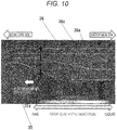
FIG. 10] FIG. 10 is a view of the gas phase volume fraction diagram of the rod protrusion part of the high-pressure fuel supply pump according to the first embodiment of the present invention in which a countermeasure shape recited in claim 5 is implemented. - [
FIG. 11] FIG. 11 is a cross-sectional view of the rod protrusion part of the high-pressure fuel supply pump according to the second embodiment of the present invention. - Embodiments of the present invention will be described below with reference to the drawings.
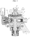
- A structure and operation of a system will be described with reference to a longitudinal cross-sectional view of a high-pressure fuel supply pump in
FIG. 1 and an entire structure diagram of the system illustrated inFIG. 8 . InFIG. 8 , a part surrounded by a broken line indicates a main body of the high-pressure fuel supply pump (hereinafter referred to as a high-pressure pump), and mechanisms and components illustrated inside this broken line are integrally incorporated in the high-pressure pump main body 1. - Fuel inside a
fuel tank 20 is pumped up by afeed pump 21 based on a signal from an engine control unit 27 (hereinafter referred to as an ECU), the fuel is pressurized up to an appropriate feed pressure and fed to a low-pressurefuel suction port 10a of the high-pressure pump through asuction pipe 28. The fuel having passed through thesuction joint 10a reaches asuction port 31b of anelectromagnetic suction valve 300 constituting a capacity variable mechanism via a pressurepulsation reduction mechanism 9 and asuction path 10d. - The fuel having flown into the
electromagnetic suction valve 300 passes through asuction valve 30 and flows into a pressurizingchamber 11. Power is applied to a plunger 2 by a cam mechanism of an engine such that the plunger can perform reciprocating motion, and the fuel is sucked from thesuction valve 30 by the reciprocating motion of the plunger 2 in a descending step of the plunger 2. Additionally, the fuel is pressurized in an ascending step of the plunger 2. When a fuel pressure in the pressurizingchamber 11 becomes higher than a fuel pressure in adischarge path 12 in this ascending stroke, a discharge valve 8 is opened. Then, the fuel is pumped, through the discharge valve 8, to acommon rail 23 on which apressure sensor 26 is mounted. The high-pressure fuel in thecommon rail 23 is injected to the engine by aninjector 24 based on a signal from theECU 27. - The high-pressure pump discharges the fuel at a flow rate so as to achieve desired supplied fuel in accordance with a signal from the
ECU 27 to the electromagnetic suction valve. Arelief valve 100 is provided in order to prevent an abnormal high pressure, and when the fuel pressure in thecommon rail 23 or thedischarge path 12 is increased to an abnormal high pressure of a setting pressure of therelief valve 100 or higher, therelief valve 100 is opened. Consequently, the fuel in thecommon rail 23 or thedischarge path 12 is returned into the pressurizingchamber 11 of the high-pressure pump, thereby preventing an abnormal high-pressure state in the common rail. - The pump main body 1 is further provided with a
relief path 110 which bypasses adischarge valve 8b and allows communication between the pressurizingchamber 11 and thedischarge path 12 on a downstream side of the discharge valve. Therelief path 110 is provided with arelief valve 102 to limit, to only one direction, a flow of the fuel from thedischarge path 12 to the pressurizingchamber 11. Therelief valve 102 is pressed against arelief valve seat 101 by arelief spring 105 that generates pressing force, and when a pressure difference between the inside of the pressurizingchamber 11 and the inside of therelief path 110 becomes a setting pressure or higher, therelief valve 102 is set so as to be separated from therelief valve seat 101 and opened. - In a case where the
common rail 23 has an abnormal high pressure due to malfunction of theelectromagnetic suction valve 300 of the high-pressure pump or the like, therelief valve 102 is opened when a pressure difference between the pressurizingchamber 11 and therelief path 110 communicating with thedischarge path 12 becomes a valve opening pressure of therelief valve 102 or higher. Consequently, the fuel having the abnormal high pressure in thedischarge path 12 is returned from therelief path 110 to the pressurizingchamber 11, and the high-pressure side pipe such as thecommon rail 23 is protected. - The structure and operation of the high-pressure pump will be described with reference to
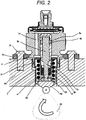
FIGS. 1 ,2 and8 . - Generally, in a high-pressure pump, a flange 1e provided in the pump main body 1 airtightly contacts a flat surface of a
cylinder head 90 of an internal combustion engine, and is fixed with a plurality ofbolts 91. The installed flange 1e is joined by welding to an entire circumference of the pump main body 1 at weldingpart 1f and forms an annular fixing part. In the present embodiment, laser welding is used. - An O-
ring 61 is fitted to the pump main body 1 in order to provide a sealing between thecylinder head 90 and the pump main body 1 and prevents leakage of engine oil to the outside. In the pump main body 1, a cylinder 6 is installed to guide the reciprocating motion of the plunger 2, and the cylinder has an end part formed in a bottomed cylinder shape so as to form a pressurizingchamber 11 inside thereof. Additionally, the pressurizingchamber 11 is provided with anannular groove 6a on an outer periphery side and a plurality ofcommunication holes 6b to provide communication between the annular groove and the pressurizing chamber so as to provide communication with theelectromagnetic suction valve 300 adapted to supply the fuel and the discharge valve mechanism 8 adapted to discharge the fuel to the discharge path from the pressurizingchamber 11. - The cylinder 6 has an outer diameter press-fitted to the pump main body 1 to provide a sealing with a press-fitted cylindrical surface so as to prevent leakage of the pressurized fuel to a low-pressure side from a gap with the pump main body 1. Additionally, the cylinder 6 has a
small diameter part 6c located at the outer diameter of the cylinder 6 on the pressurizing chamber side, and when the fuel in the pressurizingchamber 11 is pressurized, the cylinder 6 is applied with force toward a low-pressure fuel chamber 10c side, but since asmall diameter part 1a is provided in the pump main body 1, the cylinder 6 is prevented from coming out to the low-pressure fuel chamber 10c side. Since mutual surfaces of the pump main body 1 and the cylinder 6 planarly contact in an axial direction, a double sealing function is exerted in addition to the above-described sealing at the contacting cylindrical surface between the components. - The plunger 2 has a lower end provided with a
tappet 92 that converts a rotational motion of a cam installed at a camshaft of the internal combustion engine into an up-down motion and transmits the up-down motion to the plunger 2. The plunger 2 is pressure-bonded to thetappet 92 by a spring 4 via aretainer 15. Consequently, the plunger 2 can reciprocate up and down along with the rotational motion of acam 93. - Additionally, a
plunger seal 13 held at a lower end part of an inner periphery of a seal holder 7 is installed in a state slidably contacting an outer periphery of the plunger 2 at a lower part of the cylinder 6 in the drawing, and it is possible to achieve a sealable structure in which the fuel in a low-pressure chamber 7a can be sealed and prevented from leaking to the outside even in a case where the plunger 2 slides. At the same time, lubrication oil (including engine oil) that lubricates a sliding part inside the internal combustion engine is prevented from flowing into the pump main body 1. - A
damper cover 14 is fixed at a head part of the pump main body 1. Thedamper cover 14 is provided with asuction joint 51 and forms the low-pressurefuel suction port 10a. The fuel having passed through the low-pressurefuel suction port 10a passes through afilter 52 fixed inside thesuction joint 51 and reaches thesuction port 31b of theelectromagnetic suction valve 300 via the pressurepulsation reduction mechanism 9 and the low-pressurefuel flow passage 10d. - The
suction filter 52 inside thesuction joint 51 functions to prevent a foreign matter existing in a space from thefuel tank 20 to the low-pressurefuel suction port 10a from being absorbed into the high-pressure fuel supply pump by the flow of fuel. - The plunger 2 has a
large diameter part 2a and asmall diameter part 2b. When the plunger 2 reciprocates using thelarge diameter part 2a and thesmall diameter part 2b, the volume of the annular low-pressure fuel chamber 7a is increased or decreased. As for an increased/decreased amount of the volume, since the communication with the low-pressure fuel chamber 10 is provided by afuel path 1d, a flow of the flow is generated from the annular low-pressure fuel chamber 7a to the low-pressure fuel chamber 10 when the plunger 2 descends, and a flow of the fuel is generated from the low-pressure fuel chamber 10 to the annular low-pressure fuel chamber 7a when the plunger ascends. Due to this, a flow rate of the fuel to the inside/outside of the pump can be reduced in a suction step or a return step of the pump, and a function to reduce pulsation is provided. - The low-
pressure fuel chamber 10 is provided with the pressurepulsation reduction mechanism 9 that reduces pressure pulsation generated inside the high-pressure pump from being spread to thefuel pipe 28. In a case where the fuel once having flown into the pressurizingchamber 11 is returned to thesuction path 10d (suction port 31b) through thesuction valve body 30 in an open state for capacity control, pressure pulsation is generated in the low-pressure fuel chamber 10 by the fuel that has been returned to thesuction path 10d (suction port 31b). However, the pressurepulsation reduction mechanism 9 provided in the low-pressure fuel chamber 10 is formed of a metal damper obtained by bonding outer peripheries of two pieces of corrugated disk-shaped metal plates each other and injecting an inert gas such as argon into the inside thereof, and the pressure pulsation is absorbed and reduced by expansion/contraction of this metal damper. Sincereference sign 9b represents a fixing bracket to fix the metal damper to an inner periphery part of the pump main body 1 and is installed on the fuel path, a plurality of holes is provided such that fluid can be freely moved to a front side and back side of the fixingbracket 9b. - The discharge valve mechanism 8 is provided at an exit of the pressurizing
chamber 11. The discharge valve mechanism 8 includes: adischarge valve seat 8a; adischarge valve 8b that contacts and is separated from thedischarge valve seat 8a; adischarge valve spring 8c that biases thedischarge valve 8b against thedischarge valve seat 8a; and adischarge valve holder 8d housing thedischarge valve 8b and thedischarge valve seat 8a, in which the integral discharge valve mechanism 8 is formed by joining thedischarge valve seat 8a and thedischarge valve holder 8d at anabutment part 8e by welding. - Meanwhile, the inside of the
discharge valve holder 8d is provided with a steppedpart 8f forming a stopper to regulate stroking of thedischarge valve 8b. In a state where there is no fuel pressure difference between the pressurizingchamber 11 and thefuel discharge port 12, thedischarge valve 8b is in a closed state by being pressed against thedischarge valve seat 8a by the biasing force of thedischarge valve spring 8c. When the fuel pressure in the pressurizingchamber 11 becomes higher than the fuel pressure in thefuel discharge port 12, thedischarge valve 8b is opened opposing to thedischarge valve spring 8c, and the fuel inside the pressurizingchamber 11 is discharged with high pressure to thecommon rail 23 through thefuel discharge port 12. When thedischarge valve 8b is opened, thedischarge valve 8b contacts thedischarge valve stopper 8f, and the stroking thereof is regulated. - Therefore, stroking of the
discharge valve 8b is appropriately determined by thedischarge valve stopper 8d. Consequently, the fuel that has been discharged with high pressure to thefuel discharge port 12 can be prevented from flowing back into the pressurizingchamber 11 again when the stroking is excessively large and thedischarge valve 8b is closed delayed, and it is possible to suppress decrease in efficiency of the high-pressure pump. Additionally, while thedischarge valve 8b is repeatedly opened and closed, thedischarge valve 8b is guided on an inner periphery surface of thedischarge valve holder 8d so as to be moved only in a stroking direction. With the above-described structure, the discharge valve mechanism 8 functions as a check valve to regulate a flowing direction of the fuel. - With the above-described constituent elements, the pressurizing
chamber 11 includes the pump housing 1,electromagnetic suction valve 300, plunger 2, cylinder 6, and discharge valve mechanism 8. When the plunger 2 is moved in a direction of thecam 93 by the rotation of thecam 93 and is in a state of the suction step, the volume of the pressurizingchamber 11 is increased and the fuel pressure inside the pressurizingchamber 11 is decreased. When the fuel pressure inside the pressurizingchamber 11 becomes lower than a pressure in thesuction path 10d in this step, the fuel passes through thesuction valve 30 that is in an open state, passes through thecommunication hole 1b provided in the pump main body 1, passes through the cylinder outerperipheral path 6a, and flows into the pressurizingchamber 11. - After the plunger 2 terminates the suction step, the plunger 2 proceeds to the compression step. Here, an
electromagnetic coil 43 is kept in a non-energized state and is not applied with magnetic biasing force. Therefore, thesuction valve 30 remains opened by biasing force of arod biasing spring 40. The volume of the pressurizingchamber 11 is reduced along with compressing motion of the plunger 2, but the pressure of the pressurizing chamber is not increased in this state because the fuel once sucked into the pressurizingchamber 11 is returned to thesuction path 10d again through thesuction valve 30 that is in the opened state again. This step will be referred to as a return step. - In this state, when a control signal from the engine control unit 27 (hereinafter referred to as ECU) is applied to the
electromagnetic suction valve 300, current flows through theelectromagnetic coil 43, and arod 35 is moved in a direction away from thesuction valve 30 by magnetic biasing force, and thesuction valve 30 is closed by biasing force of a suctionvalve biasing spring 33 and fluid force generated by the fuel flowing into thesuction path 10d. After the suction valve is closed, the fuel pressure in the pressurizingchamber 11 is increased along with the ascending motion of the plunger 2, and when the fuel pressure becomes a pressure in thefuel discharge port 12 or higher, the fuel is discharged with high pressure via the discharge valve mechanism 8 and supplied to thecommon rail 23. This step will be referred to as a discharge step. - In other words, the compression step of the plunger 2 (ascending step from a lower start point to an upper start point) includes the return step and the discharge step. Additionally, an amount of high-pressure fuel to be discharged can be controlled by controlling energization timing to the
coil 43 from theelectromagnetic suction valve 300. When the energization timing to theelectromagnetic coil 43 is made earlier, a ratio of the return step becomes small and a ratio of the discharge step becomes large during the compression step. In other words, the amount of the fuel returned to thesuction path 10d is reduced, and the amount of the fuel discharged with the high pressure is increased. On the other hand, when the energization timing is delayed, the ratio of the return step becomes large and the ratio of the discharge step becomes small during the compression step. In other words, the amount of the fuel returned to thesuction path 10d is increased, and the amount of fuel discharged with the high pressure is reduced. The energization timing to theelectromagnetic coil 43 is controlled by a command from theECU 27. - With the above-described structure, the amount of the fuel discharged with the high pressure can be controlled so as to be an amount required from the internal combustion engine by controlling the energization timing to the
electromagnetic coil 43. - Here, the electromagnetic suction valve that is the object of the present invention will be described in detail with reference to cross-sectional views in
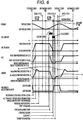
FIGS. 3 to 5 and a timing chart ofFIG. 6 . -
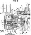
FIG. 3 is an enlarged view of theelectromagnetic suction valve 300 and illustrates a state in which theelectromagnetic coil 43 is not energized and the pressure in the pressurizing chamber 11 (the pressure pumped by the feed pump 21) is low. In this state, the suction step and the return step are performed. -
FIG. 4 is an enlarged view of theelectromagnetic suction valve 300 and illustrates a state in which: theelectromagnetic coil 43 is energized and ananchor 36 provided as a movable part contacts asecond core 39 by electromagnetic attraction force; and thesuction valve 30 is closed. -
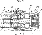
FIG. 5 is an enlarged view of theelectromagnetic suction valve 300 and illustrates a state in which energization to theelectromagnetic coil 43 is cut off in a state in which the suction valve is closed after the pressure in a pump chamber is sufficiently increased. A suction valve section includes thesuction valve 30, asuction valve seat 31, asuction valve stopper 32, the suctionvalve biasing spring 33, and asuction valve holder 34. - The
suction valve seat 31 has a cylindrical shape, includes aseat part 31a in an axial direction on an inner periphery side and two or moresuction path parts 31b radially around an axis of the cylinder, and an outer periphery cylindrical surface thereof is press-fitted and held by the pump main body 1. Thesuction valve holder 34 has claws in two or more radial directions, and an outer periphery side of each of the claws is coaxially engaged and held on the inner periphery side of thesuction valve seat 31. Additionally, thesuction stopper 32 having a cylindrical shape and having one end formed in a collar shape is press-fitted and held at an inner periphery cylindrical surface of thesuction valve holder 34. - The suction
valve biasing spring 33 is disposed on an inner periphery side of thesuction valve stopper 32 at a narrow diameter part in order to coaxially and partly stabilize one end of the spring, and thesuction valve 30 is formed between the suctionvalve seat part 31a and thesuction valve stopper 32 with the suctionvalve biasing spring 33 being engaged in avalve guide part 30b. The suctionvalve biasing spring 33 is a compression coil spring and is installed such that biasing force acts in a direction in which thesuction valve 30 is pressed against the suctionvalve seat part 31a. The suction valve biasing spring is not limited to the compression coil spring and may be any spring as far as biasing force can be obtained, and may be a leaf spring having biasing force integrated with the suction valve. - Since the suction valve section has the above-described structure, the fuel having passed through the
suction path 31b and entered the inside passes between thesuction valve 30 and theseat part 31a, passes between the outer periphery side of thesuction valve 30 and the claws of thesuction valve holder 34, and passes through the pump main body 1 and the path of the cylinder, and the fuel is made to flow into the pump chamber in the suction step of the pump. Furthermore, in the discharge step of the pump, thesuction valve 30 contacts and seals the suctionvalve seat part 31a, thereby exerting a function of a check valve to prevent the fuel from flowing back to an inlet side of the fuel. - A
path 32a is provided in order to smoothen movement of thesuction valve 30 and release a liquid pressure on the inner periphery side of the suction valve stopper in accordance with movement of the suction valve. Anaxial movement amount 30e of thesuction valve 30 is regulated by thesuction valve stopper 32 to a finite extent. When the movement amount is too large, the mentioned backflow amount is increased due to delayed response when thesuction valve 30 is closed, and performance of the pump is degraded. Such regulation of the movement amount can be determined by an axial shape dimension and a press-fitted position of each of thesuction valve seat 31a,suction valve 30, andsuction valve stopper 32. - An
annular protrusion 32b is provided in thesuction valve stopper 32 to reduce contact area with thesuction valve stopper 32 in a state where thesuction valve 32 is opened. This is to facilitate separation of thesuction valve 32 from thesuction valve stopper 32 when the suction valve is shifted from the opened state to the closed state, that is, to improve valve closing responsiveness. In a case of not having the annular protrusion, that is, in a case where the contact area is large, large squeezing force acts between thesuction valve 30 and thesuction valve stopper 32, and thesuction valve 30 is hardly separated from thesuction valve 32. - Since the
suction valve 30,suction valve seat 31a, andsuction valve stopper 32 repeatedly collide with each other during actuation, a material obtained by applying heat treatment to martensitic stainless steel provided with high strength, high hardness, and excellent corrosion resistance is used. Considering corrosion resistance, an austenitic stainless steel material is used for thesuction valve spring 33 and thesuction valve holder 34. - Next, a solenoid mechanism section will be described. The solenoid mechanism section includes: the
rod 35 and theanchor 36 which are the movable parts; arod guide 37, afirst core 38, asecond core 39 which are fixed parts; therod biasing spring 40; and ananchor biasing spring 41. - The
rod 35 and theanchor 36 provided as the movable parts are formed as separate members. Therod 35 is held slidably in the axial direction on an inner periphery side of therod guide 37, and an inner periphery side of theanchor 36 is held slidably on an outer periphery side of therod 35. In other words, both of therod 35 and theanchor 36 are axially slidable within a range geometrically regulated. - The
anchor 36 has one or more throughholes 36a penetrating the anchor in a component axial direction and eliminates, as much as possible, restriction of movement caused by a pressure difference between front and back of the anchor in order that theanchor 36 can be smoothly moved in the axial direction in the fuel. - The
rod guide 37 is radially inserted into an inner periphery side of a hole where the suction valve is inserted in the pump main body 1, and is axially made to abut on one end of the suction valve seat and disposed in a manner interposed between the pump main body 1 and thefirst core 38 fixed to the pump main body 1 by welding. - Similar to the
anchor 36, therod guide 37 is also provided with a throughhole 37a penetrating the rod guide in the axial direction such that the pressure of the fuel chamber on the anchor side does not hinder movement of the anchor in order that the anchor can be smoothly moved. - The
first core 38 has a thin-walled cylindrical shape on a side opposite to the portion welded to the pump main body, and thesecond core 39 is inserted into and fixed to an inner periphery side thereof by welding. Therod biasing spring 40 is disposed on the inner periphery side of thesecond core 39 while using a narrow diameter part as a guide, therod 35 contacts thesuction valve 30, and applies biasing force in a direction to separate the suction valve from the suctionvalve seat part 31a, that is, an opening direction of the suction valve. - The
anchor biasing spring 41 is disposed at a position to apply biasing force to theanchor 36 in a direction of arod collar part 35a while keeping an end inserted into aguide part 37b provided on a center side of therod guide 37 and having a cylindrical diameter. A movement amount 36e of theanchor 36 is set larger than themovement amount 30e of thesuction valve 30. This is to surely close thesuction valve 30. - Since the
rod 35 and therod guide 37 slide against each other and therod 35 repeatedly collides with thesuction valve 30, a material obtained by applying heat treatment to martensitic stainless steel is used considering hardness and corrosion resistance. Magnetic stainless steel is used for theanchor 36 and thesecond core 39 in order to form a magnetic circuit, and respective collision surfaces of theanchor 36 andsecond core 39 are subjected to surface treatment in order to improve hardness. Particularly, hard Cr plating or the like is used, but not limited thereto. Austenitic stainless steel is used for therod biasing spring 40 and theanchor biasing spring 41, considering corrosion resistance. - Three springs are formed in the suction valve section and the solenoid mechanism section. The suction
valve biasing spring 33 formed in the suction valve section, and therod biasing spring 40 and theanchor biasing spring 41 formed in the solenoid mechanism section are provided. In present embodiment, a coil spring is used for each of all of these springs, but any spring can be used as far as biasing force can be obtained. - A force relation between these three springs is represented by the following Expression.

- According to this relation, due to force of each of the springs, the
rod 35 has force f1 applied in the direction to separate thesuction valve 30 from the suctionvalve seat part 31a, that is, the valve opening direction during no-energization. According to Expression (1), f1 is as follows.
- Next, a structure of a coil section will be described. The coil section includes a
first yoke 42, theelectromagnetic coil 43, asecond yoke 44, abobbin 45, a terminal 46, and aconnector 47. Thecoil 43 in which a copper wire is wound around thebobbin 45 multiple times is disposed in a manner surrounded by thefirst yoke 42 and thesecond yoke 44, and fixed integrally with theconnector 47 that is a resin member by molding. One end of each of twoterminals 46 is connected to each of both ends of the copper wire of the coil in an energizable manner. Theterminals 46 are also molded integrally with theconnector 47, and a remaining end of each of the terminals is connectable to an engine control unit side. - In the coil section, a hole part at a center part of the
first yoke 42 is press-fitted and fixed to thefirst core 38. At this point, an inner diameter side of thesecond yoke 44 contacts or comes close to thesecond core 39 with a slight clearance. - Both of the
first yoke 42 and thesecond yoke 44 are formed of a magnetic stainless steel material considering corrosion resistance in order to construct a magnetic circuit, and a resin having high strength and heat resistance is used for thebobbin 45 and theconnector 47 considering strength properties and heat resistance properties. Copper is used for thecoil 43, and metal plated brass is used for theterminals 46. - Since the solenoid mechanism section and the coil section have the above-described structure, the magnetic circuit is formed of the
first core 38,first yoke 42,second yoke 44,second core 39, andanchor 36 as indicated by arrows inFIG. 3 , and when current is applied to the coil, electromagnetic force is generated between thesecond core 39 and theanchor 36, and force to attract each other is generated. In thefirst core 38, an axial portion where mutual attraction force is generated between thesecond core 39 and theanchor 36 is formed as thin as possible, and therefore, the electromagnetic force can be efficiently obtained because almost all of magnetic fluxes pass between thesecond core 39 and theanchor 36. - When the electromagnetic force exceeds the mentioned f1, it is possible to perform a motion by which the
anchor 36 that is the movable part is attracted to thesecond core 39 together with therod 35, and also, thecore 39 and theanchor 36 can contact each other and continue contacting each other. - In the following, operation and effects will be described in detail with reference to
FIGS. 3 to 5 and the timing chart inFIG. 6 . - When the plunger 2 starts descending from a top dead center, the pressure inside the pressurizing chamber is rapidly decreased from a high-pressure state of a level of, for example, 20 MPa, and the
rod 35,anchor 36, andsuction valve 30 are moved in an opening direction of thesuction valve 30 by the above-described force f1. When thesuction valve 30 is opened, the fuel having flown into an inner diameter side of thevalve seat 31 from thepath 31b of the suction valve seat starts to be sucked into the pressurizing chamber. - The
suction valve 30 collides with thesuction valve stopper 32, and thesuction valve 30 is stopped at that position. Similarly, therod 35 is also stopped at a position where a tip of the rod contacts the suction valve 30 (valve open position of the plunger rod inFIG. 6 ). - The
anchor 36 is also moved in the opening direction of thesuction valve 30 at the speed almost same as that of therod 35. However, as indicated by A inFIG. 6 , the anchor tries to continue being moved by inertial force even after therod 35 contacts thesuction valve 30 and is stopped. However, theanchor biasing spring 41 overcomes the inertia force, theanchor 36 is moved again in the direction approaching thesecond core 39, and theanchor 36 can be stopped at a position where the anchor is pressed against and contacts therod collar part 35a (valve open position of the anchor inFIG. 6 ). A state indicating the position of each of theanchor 36,rod 35, andsuction valve 30 at this point is the state illustrated inFIG. 3 . - In the above description and
FIG. 6 , it is described that therod 35 and theanchor 36 are completely separated from each other at the part indicated by A, but therod 35 and theanchor 36 may remain contacting each other. In other words, a load acting on the contact part between therod collar part 35a and theanchor 36 is reduced after the motion of the rod is stopped, and when the load becomes zero, theanchor 36 starts to be separated from the rod, but the load does not necessarily become zero, and may be setting force of theanchor biasing spring 41 while remaining a slight load. - When the
suction valve 30 collides with thesuction valve stopper 32, there is a problem of abnormal noise that is an important characteristic as a product. A level of the abnormal noise depends on the magnitude of energy at the time of collision, but since therod 35 and theanchor 36 are formed in the separate bodies, the energy colliding with thesuction valve stopper 32 is generated by mass of thesuction valve 30 and mass of therod 35. In other words, since the mass of theanchor 36 does not contribute to collision energy, the problem of abnormal noise is reduced by forming therod 35 and theanchor 36 in the separate bodies. - Even though the
rod 35 and theanchor 36 are formed in the separate bodies, in a case where theanchor biasing spring 41 is not provided, theanchor 36 continues being moved by the inertial force in the opening direction of thesuction valve 30 and collides with thecenter bearing part 37b of therod guide 37, and there is the problem that abnormal noise is generated at a part different from the collision part. Besides the problem of abnormal noise, collision causes not only abrasion, deformation, and the like of theanchor 36 and therod guide 37 but also generation of a metallic foreign matter due to the abrasion, and a bearing function may be impaired by such a foreign matter caught in the sliding part and deformed, and as a result, the function of the suction valve solenoid mechanism may be impaired. - Additionally, in the case where the
anchor biasing spring 41 is not provided, the anchor is excessively separated from the core 39 by the inertial force (part A inFIG. 6 ), and therefore, there is a problem that necessary electromagnetic attraction force cannot be obtained when current is applied to the coil section in order to shift the return step to the discharge step that is a post-step in terms of operation time. In the case where the necessary electromagnetic attraction force cannot be obtained, there is a serious problem that the fuel to be discharged from the high-pressure pump cannot be controlled at a desired flow rate. - Therefore, the
anchor biasing spring 41 has an important function to prevent occurrence of the above-described problems. After thesuction valve 30 is opened, the plunger 2 further descends and reaches a bottom dead center. During this time, the fuel continues flowing into the pressurizingchamber 11, and this step is the suction step. - The plunger 2 having descended to the bottom dead center proceeds to the ascending step. The suction valve is kept stopped in the open state by the mentioned f1, and a direction of the fluid passing through the suction valve becomes the opposite direction. In other words, while the fuel flows into the pressurizing chamber from the suction
valve seat path 31b in the suction step, the fuel is returned from the pressurizing chamber in a direction of the suctionvalve seat path 31b when the step is shifted to the ascending step. This step is called the return step. - In this return step, closing force of the suction valve by the returned fluid is increased and the mentioned force f1 becomes small at the time of high engine speed, that is, under a condition that an ascending speed of the plunger 2 is high. Under this condition, in a case where the setting force of each of the springs is set incorrectly and the f1 becomes a negative value, the
suction valve 30 is unintentionally closed. Since discharge is performed at a flow rate larger than the desired discharge flow rate, a pressure inside the fuel pipe is increased to a desired pressure or higher, thereby affecting combustion control of the engine. Therefore, it is necessary to set the force of each of the springs such that the force f1 can keep a positive value under the condition that the ascending speed of the plunger 2 is the highest. - Considering generation of electromagnetic force and delay in closing the suction valve, current is applied to the
electromagnetic coil 43 at the time earlier than desired discharge time, and magnetic attraction force acts between theanchor 36 and thesecond core 39. As for this current, the current having the magnitude enough to overcome the force f1 is needed to be applied. When the magnetic attraction force overcomes the force f1, theanchor 36 starts to be moved toward thesecond core 39. Therod 35 having thecollar part 35a that is in contact with the anchor is also moved in the axial direction along with movement of theanchor 36, and thesuction valve 30 is started to be closed by the force of the suctionvalve biasing spring 33 and fluid force, mainly, due to decrease in a static pressure caused by a flow speed at which the fluid passes through the seat part from the pressurizing chamber side. - In a case where the
anchor 36 and thesecond core 39 are excessively separated from each other more than a prescribed distance when the current is applied to theelectromagnetic coil 43, in other words, in a case where theanchor 36 continues to be in the state of A even after the "valve open position" inFIG. 6 , the magnetic attraction force is too weak to overcome the force f1, and there is a problem that it takes a quite a time to move the anchor to thesecond core 39 side or the anchor cannot be moved. - The
anchor biasing spring 41 is provided in order to prevent such a problem. In a case where theanchor 36 cannot be moved to thesecond core 39 at desired timing, the discharge step cannot be started because the suction valve is kept opened even at the timing desired to perform discharging. In short, that is, there is concern that desired engine combustion cannot be performed because a necessary discharge amount cannot be obtained. Therefore, theanchor biasing spring 41 has an important function to prevent the abnormal noise problem that may occur in the suction step and also to prevent the problem that the discharge step cannot be started. - The
suction valve 30 that has been started to be moved is made to the closed state by colliding with theseat part 31a and being stopped. When the valve is closed, a cylinder inner pressure is rapidly increased, and therefore, thesuction valve 30 is strongly pressed in the closing direction by the cylinder inner pressure with the force larger than the force f1, and the closed state is started to be kept. - Here, a description will be provided for a problem of erosion that is the problem of the present embodiment and may occur in the solenoid mechanism section. In a case where space volume between the
anchor 36 and thesecond core 39 is rapidly reduced when the current is applied to the coil and the anchor is attracted to the second core, fluid existing in the space loses a place to go. Therefore, the fluid is swept to the outer periphery side of the anchor with a fast flow, collides with the thin-walled part of the first core, and erosion may be caused by this energy. Additionally, the swept fluid passes through the outer periphery of the anchor and flows to the rod guide side, but since the path on the outer periphery side of the anchor is narrow, the flow speed becomes high. Then, cavitation may occur due to rapid decrease in the static pressure, and cavitation erosion may occur at the thin-walled part of the first core. - To avoid such problems, one or more of the axial through
holes 36a are provided on the anchor center side. The reason is to allow the fluid in the space to pass through the throughholes 36a when theanchor 36 is attracted toward thesecond core 39 side such that the fluid does not pass through the narrow path on the outer periphery side of the anchor as much as possible. - In the present embodiment, it is directed to reducing occurrence of cavitation that may cause the cavitation erosion. Since the fuel path is narrow and the flow is linear at a place where the flow speed of the fuel is high, the flow separation tends to occur at a shape having a steep angle, and as a result, the pressure is dropped, and such a state mainly causes the cavitation. Therefore, the flow speed can be gradually decreased and pressure drop can be suppressed by moderately widening the flow passage from the narrow fuel path, and as a result, the above-described problem of erosion can be solved.
- In a case where the
anchor 36 and therod 35 are integrally formed, there is another phenomenon that may cause the above-described problem. When the current is applied to the coil under the condition that engine speed is high, that is, the ascending speed of the plunger is high, the closing force of thesuction valve 30 by the fluid having an extremely fast speed is added as additional force to move theanchor 36 toward thesecond core 39, and therod 35 and theanchor 36 rapidly approach thesecond core 39, and therefore, the fluid in the space is pushed away with the even faster speed, and the problem of erosion becomes more serious. In a case where the volume of the throughhole 36a of theanchor 36 is not sufficient, the problem of erosion cannot be solved. - In the present embodiment, since the
anchor 36 and therod 35 are formed in the separate bodies, even in the case where the closing force of thesuction valve 30 is applied to therod 35, only therod 35 is pushed away toward thesecond core 39 side and moved to thesecond core 39 side only by normal electromagnetic attraction force while leaving theanchor 36 behind. In other words, the space is not rapidly reduced, and occurrence of the problem of erosion can be prevented. - As described above, the disadvantages of forming the
anchor 36 and therod 35 in the separate bodies are: incapability of obtaining desired magnetic attraction force, generation of abnormal noise, and degradation of the functions, however; the disadvantages can be eliminated by installing theanchor biasing spring 41. - Immediately after termination of the return step that is a step from when the plunger is shifted to the ascending step from the bottom dead center and the current is applied to the
coil 43 at the desired timing until when thesuction valve 30 is closed, the pressure inside the pressurizing chamber is rapidly increased and the step proceeds to the discharge step. After the discharge step, the current applied to the coil is cut off because it is desirable to reduce the power applied to the coil from the viewpoint of power saving. With no application of electromagnetic force, theanchor 36 and therod 35 are moved in a direction away from thesecond core 39 by resultant force of therod biasing spring 40 and theanchor biasing spring 41. However, since thesuction valve 30 is in the closed position by strong closing force, therod 35 is stopped at the position where the rod collides with thesuction valve 30 in the closed state. In other words, the movement amount of the rod at this point is 36e - 30e. - Thus, the discharge step to discharge the fuel is performed, and the
suction valve 30,rod 35, andanchor 36 are in the state illustrated inFIG. 5 immediately before the subsequent suction step. When the plunger reaches the top dead center, the discharge step is terminated and the suction step is started again. - Thus, the fuel guided to the low-pressure
fuel suction port 10a is pressurized to a high pressure by the reciprocating motion of the plunger 2 in the pressurizingchamber 11 of the pump main body 1 provided as the pump main body, and it is possible to provide the high-pressure pump suitable for pumping the fuel from thefuel discharge port 12 to thecommon rail 23. - As illustrated in an enlarged view of an anchor rod protrusion part in
FIG. 9 , the high-pressure pump of the present embodiment is formed such that the flow passage area between an outer periphery part 35d of theprotrusion part 35a and aninner periphery part 36c of theanchor 36 becomes the smallest in a region from aspring space 48 to thefuel path 36a formed in theanchor 36. Additionally, theprotrusion part 35a is characterized in being formed with atapered section 35c to broaden the flow passage area, and this tapered section is included in the outer periphery part 35d and has an outer diameter reduced toward thefuel path 36a from a portion 36d having the smallest flow passage area located in a region with theinner periphery part 36c. - Consequently, when a liquid flow is generated along with movement of the
anchor 36 by opening/closing of thesuction valve 30 inFIG. 4 , the flow speed is gradually decreased and pressure drop is suppressed because the flow passage is gradually broadened after the fuel passes through the smallest flow passage area 36d, and as a result, a flow separation part is reduced, thereby contributing to suppression of cavitation. - Additionally, according to the cross-sectional view of the solenoid section of the high-pressure fuel pump in
FIG. 3 , the high-pressure fuel supply pump having the above-described structure is characterized in that the fuel in thespring space 48 where thespring 40 is disposed is made to flow to thesuction valve 30 side via thefuel path 36a and afuel path 36f in the case where theanchor 36 is moved toward thesecond core 39. As a result, the fuel can be moved by operation of the anchor. - Furthermore, according to the enlarged view of the anchor rod protrusion part in
FIG. 9 , the high-pressure fuel supply pump having the above-described structure is characterized in that the taperedsection 35c has the outer diameter gradually reduced toward thefuel path 36a and broadens the flow passage area. Consequently, since the flow passage area is broadened after the fuel passes through the smallest flow passage area 36d, the flow speed of the fuel is decreased, and this contributes to reduction of the flow separation part. - Furthermore, as illustrated in an enlarged view of the anchor rod protrusion part in
FIG. 10 , the high-pressure fuel supply pump having the above-described structure of the present embodiment is characterized in that thetaper 35c is engaged with theanchor 36 more on the inner periphery side than thefuel path 36a of theanchor 36. Consequently, the flow passage area is broadened after the fuel passes through the smallest flow passage area 36d, and this contributes to decrease in the flow speed. - Additionally, in the high-pressure fuel supply pump having the above-described structure, the structure of
FIG. 9 can also contribute to suppression of cavitation as described above. However, even in structure ofFIG. 9 , there is a place where cavitation may occur due to pressure drop caused by flow separation. Therefore, the embodiment of the present invention illustrated inFIG. 10 is characterized in that the taperedsection 35c is formed such that an end part on the fuel path side of the tapered section is located at a position corresponding to an innermost periphery side of thefuel path 36a. In other words, there is no stepped part in a region from the taperedsection 35c to the rod part as illustrated inFIG. 9 , and the taperedsection 35c and the rod part are smoothly connected. Consequently, since the flow passage area of the smallest flow passage area part 36d is broadened, the flow speed of the fuel is decreased, and this contributes to suppression of cavitation by reduction of the flow separation part. - Furthermore, according to the cross-sectional view of the solenoid section of the high-pressure fuel supply pump when the suction valve is opened in
FIG. 3 , the high-pressure fuel supply pump having the above-described structure is characterized in that therod 35 includes acylindrical part 35e having a diameter smaller than that of theprotrusion part 35a and extending toward thespring 40 side, and the cylindrical part has anend part 35f formed at a position corresponding to an end face of thesecond core 39 facing theanchor 36. This contributes to prevention of magnetic leakage from the cylindrical part to the second core. - Additionally, according to the cross-sectional view of the solenoid section when the suction valve is closed in
FIG. 3 , the high-pressure fuel supply pump having the above-described structure is characterized in that therod 35 includes thecylindrical part 35e having the diameter smaller than that of theprotrusion part 35a and extending toward thespring 40 side, the protrusion part and the cylindrical part are disposed on an inner periphery side of a recessedpart 36g formed in the anchor, and thecylindrical part 35e is formed such that theend part 35f of the cylindrical part formed at the position corresponding to the end face of thesecond core 39 facing theanchor 36. - Furthermore, according to the cross-sectional view of the solenoid section when the suction valve is closed in
FIG. 4 , the high-pressure fuel supply pump having the above-described structure is characterized in that therod 35 includes thecylindrical part 35e having the diameter smaller than that of theprotrusion part 35a and extending toward thespring 40 side, theprotrusion part 35a and thecylindrical part 35e are disposed on the inner periphery side of the recessedpart 36g formed in theanchor 36, and thespring 40 is held by being wounded around thecylindrical part 35e. Consequently, there is an effect of stabilizing a posture of thespring 40. - Additionally, according to the cross-sectional view of the solenoid section when the suction valve is closed in
FIG. 4 , the high-pressure fuel supply pump having the above-described structure is characterized in that thespring 40 is wound around thecylindrical part 35e 1.5 turns or more. Consequently, there is an effect of stabilizing a posture of thespring 40. - Furthermore, according to the cross-sectional view of the solenoid section when the suction valve is closed in
FIG. 4 , the high-pressure fuel supply pump having the above-described structure is characterized in that therod 35 includes thecylindrical part 35e having the diameter smaller than that of theprotrusion part 35a and extending toward thespring 40 side, thefuel path 36a of theanchor 36 is formed in a manner overlapping with an inner periphery surface of the recessed part formed in thesecond core 39 in the movement direction of theanchor 36, and the outer periphery part of thecylindrical part 35e is located more on the inner periphery side than the innermost periphery side of thefuel path 36a. Consequently, a flow passage through which the fuel in thespring space 48 is moved can be secured. - Additionally, according to the cross-sectional view of the solenoid section when the suction valve is closed in
FIG. 4 , the high-pressure fuel supply pump having the above-described structure is characterized in that therod 35 includes thecylindrical part 35e having the diameter smaller than that of theprotrusion part 35a and extending toward thespring 40 side, and the flow passage area between the outer periphery part 35d of theprotrusion part 35a and the inner periphery part of theanchor 36 is smaller than that of thefuel flow passage 36a between thecylindrical part 35e and thesecond core 39. - Consequently, since the flow speed in the flow passage between the outer periphery part 35d and the inner periphery part of the
anchor 36 becomes faster, the flow separation part can be reduced by the taper of the present invention. - As described above, cavitation is more likely to occur in the structure of
FIG. 9 than in the structure ofFIG. 10 . The reasons will be described below. The fuel path inside theanchor 36 is illustrated inFIG. 9 , and magnetic attraction force is generated between theanchor 36 and thesecond core 39 by energizing theelectromagnetic coil 43, and the fluid is pushed way by movement of theanchor 36 and therod 35 toward the second core side, and flow toward the suction valve side through thecombustion path 36a. At this point, a flow separation part is generated and the pressure drops due to influence of the flow after the fluid passes through the vicinity of therod protrusion part 35a, and cavitation occurs. - In contrast, in
FIG. 10 , inFIG. 9 illustrating the enlarge view of the anchor rod protrusion part in the present embodiment, flow separation is caused in the vicinity of therod protrusion part 35a when the fluid is pushed away toward the suction valve side due to movement of therod 35 toward the second core side as described above. On the other hand, in present embodiment, since theprotrusion part 35a is provided with the taper as illustrated inFIG. 10 , the inside of the fuel path is formed smooth without having any step. Consequently, flow separation can be reduced by rectifying the fuel flow, and occurrence of cavitation can be suppressed. -
FIG. 11 is an enlarged view of the anchor/anchor rod protrusion part in the present embodiment. As illustrated in arod protrusion part 35a, since the taper is provided in each of asecond core side 35b and asuction valve side 35c of the protrusion part, and therefore, it is possible to reduce a flow separation part generated in the vicinity of the protrusion part along with movement of an anchor at the time of opening/closing the suction valve, and occurrence of cavitation can be suppressed. - As illustrated in
FIG. 11 , since a taper or a gentle curved surface is provided at therod protrusion part 35a and aprotrusion part 36b of an anchor is provided, it is possible to reduce the flow separation part generated in the vicinity of the protrusion parts along with movement of arod 35 at the time of opening/closing the suction valve, and occurrence of cavitation is suppressed Reference Signs List -
- 1
- pump main body
- 2
- plunger
- 6
- cylinder
- 7
- seal holder
- 8
- discharge valve mechanism
- 9
- pressure pulsation reduction mechanism
- 10a
- low-pressure fuel suction port
- 11
- pressurizing chamber
- 12
- fuel discharge port
- 13
- plunger seal
- 30
- suction valve
- 31
- suction valve seat
- 33
- suction valve spring
- 35
- rod
- 35a
- rod protrusion part
- 35b
- second core side of rod protrusion part
- 35c
- suction valve side of rod protrusion part
- 35d
- outer diameter of rod protrusion part
- 36
- anchor
- 36a
- fuel path
- 36b
- anchor protrusion part
- 36c
- inner periphery part of anchor
- 36d
- flow passage area smallest part
- 36f
- fuel path (side gap part)
- 38
- first core
- 39
- second core
- 40
- rod biasing spring
- 41
- anchor biasing spring
- 43
- electromagnetic coil
- 48
- spring space
- 300
- electromagnetic suction valve
Claims (8)
- A high-pressure fuel supply pump comprising:- a suction valve (30) provided on a suction side of a pressurizing chamber (11);- an engagement member (36) having a protrusion part (36b) which protrudes toward an outer periphery side and biases the suction valve (30) by use of force of a spring;- a stator which generates magnetic attraction force; and- a movable element (36) which is sucked by the magnetic attraction force and drives the engagement member (35) toward the stator by being engaged with the protrusion part (35b), whereinflow passage area between an outer periphery part of the protrusion part (35b) and an inner periphery part of the movable element (36) is formed smallest in a region from the spring space to a fuel path (36a) formed in the movable element (36), andthe protrusion part (35b) is further formed with a tapered section which broadens flow passage area, and the tapered section is included in the outer periphery part of the protrusion part (35b) and has an outer diameter reduced toward the fuel path (36a) from a portion having the smallest flow passage area in a region with the inner periphery part, whereinthe engagement member (35) has a cylindrical part having a diameter smaller than a diameter of the protrusion part (35b) and extending toward the spring, and wherein the protrusion part (35b) and the cylindrical part are disposed on an inner periphery side of a recessed part (36g) formed in the movable element (36),characterized in that:the spring is held by being wounded around the cylindrical part on the inner periphery side of the recessed part (36g), and whereinthe flow passage area between the outer periphery part of the protrusion part (35b) and the inner periphery part of the movable element (36) is smaller than a fuel flow passage between the cylindrical part and the stator.
- The high-pressure fuel supply pump according to claim 1, wherein
the fuel path (36a) is formed with a fuel path (36f) in which fuel in the spring space where the spring is disposed is made to flow into the pressurizing chamber (11) in a case where the movable element (36) is moved toward the stator. - The high-pressure fuel supply pump according to claim 1, wherein
the tapered section is formed such that the outer diameter is gradually reduced toward the fuel path (36a) so as to broaden the flow passage area. - The high-pressure fuel supply pump according to claim 1, wherein
the protrusion part (35a) is engaged with the movable element (36) more on an inner periphery side than the fuel path (36a) of the movable element (36). - The high-pressure fuel supply pump according to claim 4, wherein
the tapered section is formed such that an end part of the tapered section on the side of the fuel path (36a) is located at a position corresponding to an innermost periphery side of the fuel path (36a). - The high-pressure fuel supply pump according to claim 1, whereinthe engagement member (35) has a cylindrical part having a diameter smaller than a diameter of the protrusion part (35b) and extending toward the spring side, andthe cylindrical part is formed such that an end part of the cylindrical part is located at a position corresponding to an end surface of the stator facing the movable element (36).
- The high-pressure fuel supply pump according to claim 1, wherein
the spring is wound around the cylindrical part 1.5 turns or more. - The high-pressure fuel supply pump according to claim 1, whereinthe engagement member (35) has a cylindrical part having a diameter smaller than a diameter of the protrusion part (35b) and extending toward the spring side,the fuel path (36a) of the movable element (36) is formed in a manner overlapping with an inner periphery surface of the recessed part (36g) formed in the stator in the movement direction of the movable element (36), andthe outer periphery part of the cylindrical part is located more on the inner periphery side than the innermost periphery side of the fuel path (36a).
Applications Claiming Priority (2)
| Application Number | Priority Date | Filing Date | Title |
|---|---|---|---|
| JP2016188990 | 2016-09-28 | ||
| PCT/JP2017/027988 WO2018061471A1 (en) | 2016-09-28 | 2017-08-02 | High-pressure fuel supply pump |
Publications (3)
| Publication Number | Publication Date |
|---|---|
| EP3521608A1 EP3521608A1 (en) | 2019-08-07 |
| EP3521608A4 EP3521608A4 (en) | 2020-05-20 |
| EP3521608B1 true EP3521608B1 (en) | 2021-10-06 |
Family
ID=61763376
Family Applications (1)
| Application Number | Title | Priority Date | Filing Date |
|---|---|---|---|
| EP17855429.1A Active EP3521608B1 (en) | 2016-09-28 | 2017-08-02 | High-pressure fuel supply pump |
Country Status (4)
| Country | Link |
|---|---|
| US (1) | US10731616B2 (en) |
| EP (1) | EP3521608B1 (en) |
| JP (1) | JP6817316B2 (en) |
| WO (1) | WO2018061471A1 (en) |
Families Citing this family (4)
| Publication number | Priority date | Publication date | Assignee | Title |
|---|---|---|---|---|
| JP6586931B2 (en) * | 2016-08-26 | 2019-10-09 | 株式会社デンソー | Relief valve device and high-pressure pump using the same |
| JP7019816B2 (en) * | 2018-07-27 | 2022-02-15 | 日立Astemo株式会社 | Fuel pump |
| WO2022147125A1 (en) * | 2020-12-31 | 2022-07-07 | Cummins Inc. | Fuel pump |
| US11352994B1 (en) * | 2021-01-12 | 2022-06-07 | Delphi Technologies Ip Limited | Fuel pump and combination outlet and pressure relief valve thereof |
Family Cites Families (9)
| Publication number | Priority date | Publication date | Assignee | Title |
|---|---|---|---|---|
| JP2005139953A (en) | 2003-11-05 | 2005-06-02 | Denso Corp | Fuel pressure control valve |
| JP5537498B2 (en) | 2011-06-01 | 2014-07-02 | 日立オートモティブシステムズ株式会社 | High pressure fuel supply pump with electromagnetic suction valve |
| JP5881530B2 (en) * | 2012-05-22 | 2016-03-09 | 日立オートモティブシステムズ株式会社 | Pump device |
| JP5830492B2 (en) * | 2013-05-24 | 2015-12-09 | 株式会社日本自動車部品総合研究所 | High pressure pump |
| JP6173959B2 (en) * | 2014-03-28 | 2017-08-02 | 日立オートモティブシステムズ株式会社 | Solenoid valve, high pressure fuel supply pump equipped with solenoid valve, and fuel injection valve |
| CN106795846B (en) | 2014-08-28 | 2019-05-03 | 日立汽车系统株式会社 | High pressure fuel supply pump |
| JP2016094913A (en) | 2014-11-17 | 2016-05-26 | 日立オートモティブシステムズ株式会社 | High pressure fuel supply pump |
| JP2016142143A (en) | 2015-01-30 | 2016-08-08 | 日立オートモティブシステムズ株式会社 | High pressure fuel supply pump |
| GB2549141A (en) * | 2016-04-08 | 2017-10-11 | Delphi Int Operations Luxembourg Sarl | Fuel pump |
-
2017
- 2017-08-02 US US16/330,890 patent/US10731616B2/en active Active
- 2017-08-02 WO PCT/JP2017/027988 patent/WO2018061471A1/en not_active Ceased
- 2017-08-02 EP EP17855429.1A patent/EP3521608B1/en active Active
- 2017-08-02 JP JP2018541965A patent/JP6817316B2/en not_active Expired - Fee Related
Also Published As
| Publication number | Publication date |
|---|---|
| EP3521608A4 (en) | 2020-05-20 |
| US20190211788A1 (en) | 2019-07-11 |
| JPWO2018061471A1 (en) | 2019-06-24 |
| WO2018061471A1 (en) | 2018-04-05 |
| JP6817316B2 (en) | 2021-01-20 |
| EP3521608A1 (en) | 2019-08-07 |
| US10731616B2 (en) | 2020-08-04 |
Similar Documents
| Publication | Publication Date | Title |
|---|---|---|
| JP6293290B2 (en) | High pressure fuel supply pump | |
| US10731615B2 (en) | Flow rate control valve and high-pressure fuel supply pump | |
| EP3608534B1 (en) | High-pressure fuel pump | |
| JP2016094913A (en) | High pressure fuel supply pump | |
| EP3521608B1 (en) | High-pressure fuel supply pump | |
| US11542903B2 (en) | High-pressure fuel supply pump provided with electromagnetic intake valve | |
| JP6689178B2 (en) | High pressure fuel supply pump | |
| EP3135969B1 (en) | Electromagnetic valve | |
| JP2021014791A (en) | High-pressure fuel pump | |
| EP3467298B1 (en) | Device for controlling high-pressure fuel supply pump, and high-pressure fuel supply pump | |
| EP3647584B1 (en) | High-pressure fuel supply pump | |
| JP6770193B2 (en) | High pressure fuel supply pump | |
| JP6959109B2 (en) | Relief valve mechanism and fuel supply pump equipped with it | |
| JP2017145731A (en) | High pressure fuel supply pump | |
| JP7077212B2 (en) | High pressure fuel pump | |
| WO2024084567A1 (en) | Fuel pump | |
| JPWO2020090371A1 (en) | Fuel pump |
Legal Events
| Date | Code | Title | Description |
|---|---|---|---|
| STAA | Information on the status of an ep patent application or granted ep patent |
Free format text: STATUS: THE INTERNATIONAL PUBLICATION HAS BEEN MADE |
|
| PUAI | Public reference made under article 153(3) epc to a published international application that has entered the european phase |
Free format text: ORIGINAL CODE: 0009012 |
|
| STAA | Information on the status of an ep patent application or granted ep patent |
Free format text: STATUS: REQUEST FOR EXAMINATION WAS MADE |
|
| 17P | Request for examination filed |
Effective date: 20190429 |
|
| AK | Designated contracting states |
Kind code of ref document: A1 Designated state(s): AL AT BE BG CH CY CZ DE DK EE ES FI FR GB GR HR HU IE IS IT LI LT LU LV MC MK MT NL NO PL PT RO RS SE SI SK SM TR |
|
| AX | Request for extension of the european patent |
Extension state: BA ME |
|
| DAV | Request for validation of the european patent (deleted) | ||
| DAX | Request for extension of the european patent (deleted) | ||
| A4 | Supplementary search report drawn up and despatched |
Effective date: 20200417 |
|
| RIC1 | Information provided on ipc code assigned before grant |
Ipc: F02M 59/34 20060101ALI20200413BHEP Ipc: F02M 59/36 20060101AFI20200413BHEP |
|
| GRAP | Despatch of communication of intention to grant a patent |
Free format text: ORIGINAL CODE: EPIDOSNIGR1 |
|
| STAA | Information on the status of an ep patent application or granted ep patent |
Free format text: STATUS: GRANT OF PATENT IS INTENDED |
|
| INTG | Intention to grant announced |
Effective date: 20210330 |
|
| RIN1 | Information on inventor provided before grant (corrected) |
Inventor name: TAKAHASHI, YUUKI Inventor name: TOKUO, KENICHIRO Inventor name: YOSHINARI, YUKIHIRO Inventor name: KODAMA, YUITSU |
|
| GRAS | Grant fee paid |
Free format text: ORIGINAL CODE: EPIDOSNIGR3 |
|
| GRAA | (expected) grant |
Free format text: ORIGINAL CODE: 0009210 |
|
| STAA | Information on the status of an ep patent application or granted ep patent |
Free format text: STATUS: THE PATENT HAS BEEN GRANTED |
|
| RAP3 | Party data changed (applicant data changed or rights of an application transferred) |
Owner name: HITACHI ASTEMO, LTD. |
|
| AK | Designated contracting states |
Kind code of ref document: B1 Designated state(s): AL AT BE BG CH CY CZ DE DK EE ES FI FR GB GR HR HU IE IS IT LI LT LU LV MC MK MT NL NO PL PT RO RS SE SI SK SM TR |
|
| REG | Reference to a national code |
Ref country code: GB Ref legal event code: FG4D |
|
| REG | Reference to a national code |
Ref country code: CH Ref legal event code: EP Ref country code: AT Ref legal event code: REF Ref document number: 1436439 Country of ref document: AT Kind code of ref document: T Effective date: 20211015 |
|
| REG | Reference to a national code |
Ref country code: IE Ref legal event code: FG4D |
|
| REG | Reference to a national code |
Ref country code: DE Ref legal event code: R096 Ref document number: 602017047335 Country of ref document: DE |
|
| REG | Reference to a national code |
Ref country code: LT Ref legal event code: MG9D |
|
| REG | Reference to a national code |
Ref country code: NL Ref legal event code: MP Effective date: 20211006 |
|
| REG | Reference to a national code |
Ref country code: AT Ref legal event code: MK05 Ref document number: 1436439 Country of ref document: AT Kind code of ref document: T Effective date: 20211006 |
|
| PG25 | Lapsed in a contracting state [announced via postgrant information from national office to epo] |
Ref country code: RS Free format text: LAPSE BECAUSE OF FAILURE TO SUBMIT A TRANSLATION OF THE DESCRIPTION OR TO PAY THE FEE WITHIN THE PRESCRIBED TIME-LIMIT Effective date: 20211006 Ref country code: LT Free format text: LAPSE BECAUSE OF FAILURE TO SUBMIT A TRANSLATION OF THE DESCRIPTION OR TO PAY THE FEE WITHIN THE PRESCRIBED TIME-LIMIT Effective date: 20211006 Ref country code: FI Free format text: LAPSE BECAUSE OF FAILURE TO SUBMIT A TRANSLATION OF THE DESCRIPTION OR TO PAY THE FEE WITHIN THE PRESCRIBED TIME-LIMIT Effective date: 20211006 Ref country code: BG Free format text: LAPSE BECAUSE OF FAILURE TO SUBMIT A TRANSLATION OF THE DESCRIPTION OR TO PAY THE FEE WITHIN THE PRESCRIBED TIME-LIMIT Effective date: 20220106 Ref country code: AT Free format text: LAPSE BECAUSE OF FAILURE TO SUBMIT A TRANSLATION OF THE DESCRIPTION OR TO PAY THE FEE WITHIN THE PRESCRIBED TIME-LIMIT Effective date: 20211006 |
|
| PG25 | Lapsed in a contracting state [announced via postgrant information from national office to epo] |
Ref country code: IS Free format text: LAPSE BECAUSE OF FAILURE TO SUBMIT A TRANSLATION OF THE DESCRIPTION OR TO PAY THE FEE WITHIN THE PRESCRIBED TIME-LIMIT Effective date: 20220206 Ref country code: SE Free format text: LAPSE BECAUSE OF FAILURE TO SUBMIT A TRANSLATION OF THE DESCRIPTION OR TO PAY THE FEE WITHIN THE PRESCRIBED TIME-LIMIT Effective date: 20211006 Ref country code: PT Free format text: LAPSE BECAUSE OF FAILURE TO SUBMIT A TRANSLATION OF THE DESCRIPTION OR TO PAY THE FEE WITHIN THE PRESCRIBED TIME-LIMIT Effective date: 20220207 Ref country code: PL Free format text: LAPSE BECAUSE OF FAILURE TO SUBMIT A TRANSLATION OF THE DESCRIPTION OR TO PAY THE FEE WITHIN THE PRESCRIBED TIME-LIMIT Effective date: 20211006 Ref country code: NO Free format text: LAPSE BECAUSE OF FAILURE TO SUBMIT A TRANSLATION OF THE DESCRIPTION OR TO PAY THE FEE WITHIN THE PRESCRIBED TIME-LIMIT Effective date: 20220106 Ref country code: NL Free format text: LAPSE BECAUSE OF FAILURE TO SUBMIT A TRANSLATION OF THE DESCRIPTION OR TO PAY THE FEE WITHIN THE PRESCRIBED TIME-LIMIT Effective date: 20211006 Ref country code: LV Free format text: LAPSE BECAUSE OF FAILURE TO SUBMIT A TRANSLATION OF THE DESCRIPTION OR TO PAY THE FEE WITHIN THE PRESCRIBED TIME-LIMIT Effective date: 20211006 Ref country code: HR Free format text: LAPSE BECAUSE OF FAILURE TO SUBMIT A TRANSLATION OF THE DESCRIPTION OR TO PAY THE FEE WITHIN THE PRESCRIBED TIME-LIMIT Effective date: 20211006 Ref country code: GR Free format text: LAPSE BECAUSE OF FAILURE TO SUBMIT A TRANSLATION OF THE DESCRIPTION OR TO PAY THE FEE WITHIN THE PRESCRIBED TIME-LIMIT Effective date: 20220107 Ref country code: ES Free format text: LAPSE BECAUSE OF FAILURE TO SUBMIT A TRANSLATION OF THE DESCRIPTION OR TO PAY THE FEE WITHIN THE PRESCRIBED TIME-LIMIT Effective date: 20211006 |
|
| REG | Reference to a national code |
Ref country code: DE Ref legal event code: R097 Ref document number: 602017047335 Country of ref document: DE |
|
| PG25 | Lapsed in a contracting state [announced via postgrant information from national office to epo] |
Ref country code: SM Free format text: LAPSE BECAUSE OF FAILURE TO SUBMIT A TRANSLATION OF THE DESCRIPTION OR TO PAY THE FEE WITHIN THE PRESCRIBED TIME-LIMIT Effective date: 20211006 Ref country code: SK Free format text: LAPSE BECAUSE OF FAILURE TO SUBMIT A TRANSLATION OF THE DESCRIPTION OR TO PAY THE FEE WITHIN THE PRESCRIBED TIME-LIMIT Effective date: 20211006 Ref country code: RO Free format text: LAPSE BECAUSE OF FAILURE TO SUBMIT A TRANSLATION OF THE DESCRIPTION OR TO PAY THE FEE WITHIN THE PRESCRIBED TIME-LIMIT Effective date: 20211006 Ref country code: EE Free format text: LAPSE BECAUSE OF FAILURE TO SUBMIT A TRANSLATION OF THE DESCRIPTION OR TO PAY THE FEE WITHIN THE PRESCRIBED TIME-LIMIT Effective date: 20211006 Ref country code: DK Free format text: LAPSE BECAUSE OF FAILURE TO SUBMIT A TRANSLATION OF THE DESCRIPTION OR TO PAY THE FEE WITHIN THE PRESCRIBED TIME-LIMIT Effective date: 20211006 Ref country code: CZ Free format text: LAPSE BECAUSE OF FAILURE TO SUBMIT A TRANSLATION OF THE DESCRIPTION OR TO PAY THE FEE WITHIN THE PRESCRIBED TIME-LIMIT Effective date: 20211006 |
|
| PLBE | No opposition filed within time limit |
Free format text: ORIGINAL CODE: 0009261 |
|
| STAA | Information on the status of an ep patent application or granted ep patent |
Free format text: STATUS: NO OPPOSITION FILED WITHIN TIME LIMIT |
|
| 26N | No opposition filed |
Effective date: 20220707 |
|
| PG25 | Lapsed in a contracting state [announced via postgrant information from national office to epo] |
Ref country code: AL Free format text: LAPSE BECAUSE OF FAILURE TO SUBMIT A TRANSLATION OF THE DESCRIPTION OR TO PAY THE FEE WITHIN THE PRESCRIBED TIME-LIMIT Effective date: 20211006 |
|
| PG25 | Lapsed in a contracting state [announced via postgrant information from national office to epo] |
Ref country code: SI Free format text: LAPSE BECAUSE OF FAILURE TO SUBMIT A TRANSLATION OF THE DESCRIPTION OR TO PAY THE FEE WITHIN THE PRESCRIBED TIME-LIMIT Effective date: 20211006 |
|
| PG25 | Lapsed in a contracting state [announced via postgrant information from national office to epo] |
Ref country code: MC Free format text: LAPSE BECAUSE OF FAILURE TO SUBMIT A TRANSLATION OF THE DESCRIPTION OR TO PAY THE FEE WITHIN THE PRESCRIBED TIME-LIMIT Effective date: 20211006 |
|
| REG | Reference to a national code |
Ref country code: CH Ref legal event code: PL |
|
| GBPC | Gb: european patent ceased through non-payment of renewal fee |
Effective date: 20220802 |
|
| PG25 | Lapsed in a contracting state [announced via postgrant information from national office to epo] |
Ref country code: LU Free format text: LAPSE BECAUSE OF NON-PAYMENT OF DUE FEES Effective date: 20220802 Ref country code: LI Free format text: LAPSE BECAUSE OF NON-PAYMENT OF DUE FEES Effective date: 20220831 Ref country code: CH Free format text: LAPSE BECAUSE OF NON-PAYMENT OF DUE FEES Effective date: 20220831 |
|
| REG | Reference to a national code |
Ref country code: BE Ref legal event code: MM Effective date: 20220831 |
|
| PG25 | Lapsed in a contracting state [announced via postgrant information from national office to epo] |
Ref country code: IT Free format text: LAPSE BECAUSE OF FAILURE TO SUBMIT A TRANSLATION OF THE DESCRIPTION OR TO PAY THE FEE WITHIN THE PRESCRIBED TIME-LIMIT Effective date: 20211006 |
|
| PG25 | Lapsed in a contracting state [announced via postgrant information from national office to epo] |
Ref country code: IE Free format text: LAPSE BECAUSE OF NON-PAYMENT OF DUE FEES Effective date: 20220802 Ref country code: FR Free format text: LAPSE BECAUSE OF NON-PAYMENT OF DUE FEES Effective date: 20220831 |
|
| PG25 | Lapsed in a contracting state [announced via postgrant information from national office to epo] |
Ref country code: BE Free format text: LAPSE BECAUSE OF NON-PAYMENT OF DUE FEES Effective date: 20220831 |
|
| PG25 | Lapsed in a contracting state [announced via postgrant information from national office to epo] |
Ref country code: GB Free format text: LAPSE BECAUSE OF NON-PAYMENT OF DUE FEES Effective date: 20220802 |
|
| PG25 | Lapsed in a contracting state [announced via postgrant information from national office to epo] |
Ref country code: HU Free format text: LAPSE BECAUSE OF FAILURE TO SUBMIT A TRANSLATION OF THE DESCRIPTION OR TO PAY THE FEE WITHIN THE PRESCRIBED TIME-LIMIT; INVALID AB INITIO Effective date: 20170802 |
|
| PG25 | Lapsed in a contracting state [announced via postgrant information from national office to epo] |
Ref country code: MK Free format text: LAPSE BECAUSE OF FAILURE TO SUBMIT A TRANSLATION OF THE DESCRIPTION OR TO PAY THE FEE WITHIN THE PRESCRIBED TIME-LIMIT Effective date: 20211006 Ref country code: CY Free format text: LAPSE BECAUSE OF FAILURE TO SUBMIT A TRANSLATION OF THE DESCRIPTION OR TO PAY THE FEE WITHIN THE PRESCRIBED TIME-LIMIT Effective date: 20211006 |
|
| PG25 | Lapsed in a contracting state [announced via postgrant information from national office to epo] |
Ref country code: TR Free format text: LAPSE BECAUSE OF FAILURE TO SUBMIT A TRANSLATION OF THE DESCRIPTION OR TO PAY THE FEE WITHIN THE PRESCRIBED TIME-LIMIT Effective date: 20211006 |
|
| PG25 | Lapsed in a contracting state [announced via postgrant information from national office to epo] |
Ref country code: MT Free format text: LAPSE BECAUSE OF FAILURE TO SUBMIT A TRANSLATION OF THE DESCRIPTION OR TO PAY THE FEE WITHIN THE PRESCRIBED TIME-LIMIT Effective date: 20211006 |
|
| PGFP | Annual fee paid to national office [announced via postgrant information from national office to epo] |
Ref country code: DE Payment date: 20250702 Year of fee payment: 9 |