EP3521550A1 - Apparatus for rod handling, rock drilling unit and method - Google Patents
Apparatus for rod handling, rock drilling unit and method Download PDFInfo
- Publication number
- EP3521550A1 EP3521550A1 EP18154331.5A EP18154331A EP3521550A1 EP 3521550 A1 EP3521550 A1 EP 3521550A1 EP 18154331 A EP18154331 A EP 18154331A EP 3521550 A1 EP3521550 A1 EP 3521550A1
- Authority
- EP
- European Patent Office
- Prior art keywords
- rod
- drilling
- rods
- unit
- swing device
- Prior art date
- Legal status (The legal status is an assumption and is not a legal conclusion. Google has not performed a legal analysis and makes no representation as to the accuracy of the status listed.)
- Granted
Links
Images


Classifications
-
- E—FIXED CONSTRUCTIONS
- E21—EARTH OR ROCK DRILLING; MINING
- E21B—EARTH OR ROCK DRILLING; OBTAINING OIL, GAS, WATER, SOLUBLE OR MELTABLE MATERIALS OR A SLURRY OF MINERALS FROM WELLS
- E21B19/00—Handling rods, casings, tubes or the like outside the borehole, e.g. in the derrick; Apparatus for feeding the rods or cables
- E21B19/14—Racks, ramps, troughs or bins, for holding the lengths of rod singly or connected; Handling between storage place and borehole
- E21B19/15—Racking of rods in horizontal position; Handling between horizontal and vertical position
- E21B19/155—Handling between horizontal and vertical position
-
- E—FIXED CONSTRUCTIONS
- E21—EARTH OR ROCK DRILLING; MINING
- E21B—EARTH OR ROCK DRILLING; OBTAINING OIL, GAS, WATER, SOLUBLE OR MELTABLE MATERIALS OR A SLURRY OF MINERALS FROM WELLS
- E21B15/00—Supports for the drilling machine, e.g. derricks or masts
- E21B15/04—Supports for the drilling machine, e.g. derricks or masts specially adapted for directional drilling, e.g. slant hole rigs
-
- E—FIXED CONSTRUCTIONS
- E21—EARTH OR ROCK DRILLING; MINING
- E21B—EARTH OR ROCK DRILLING; OBTAINING OIL, GAS, WATER, SOLUBLE OR MELTABLE MATERIALS OR A SLURRY OF MINERALS FROM WELLS
- E21B19/00—Handling rods, casings, tubes or the like outside the borehole, e.g. in the derrick; Apparatus for feeding the rods or cables
- E21B19/08—Apparatus for feeding the rods or cables; Apparatus for increasing or decreasing the pressure on the drilling tool; Apparatus for counterbalancing the weight of the rods
- E21B19/087—Apparatus for feeding the rods or cables; Apparatus for increasing or decreasing the pressure on the drilling tool; Apparatus for counterbalancing the weight of the rods by means of a swinging arm
-
- E—FIXED CONSTRUCTIONS
- E21—EARTH OR ROCK DRILLING; MINING
- E21B—EARTH OR ROCK DRILLING; OBTAINING OIL, GAS, WATER, SOLUBLE OR MELTABLE MATERIALS OR A SLURRY OF MINERALS FROM WELLS
- E21B19/00—Handling rods, casings, tubes or the like outside the borehole, e.g. in the derrick; Apparatus for feeding the rods or cables
- E21B19/14—Racks, ramps, troughs or bins, for holding the lengths of rod singly or connected; Handling between storage place and borehole
-
- E—FIXED CONSTRUCTIONS
- E21—EARTH OR ROCK DRILLING; MINING
- E21B—EARTH OR ROCK DRILLING; OBTAINING OIL, GAS, WATER, SOLUBLE OR MELTABLE MATERIALS OR A SLURRY OF MINERALS FROM WELLS
- E21B19/00—Handling rods, casings, tubes or the like outside the borehole, e.g. in the derrick; Apparatus for feeding the rods or cables
- E21B19/20—Combined feeding from rack and connecting, e.g. automatically
Definitions
- the invention relates to an apparatus for handling rods in rock drilling and especially in core drilling.
- the invention further relates to a rock drilling unit and a method of handling rock drilling rods.
- Core drilling is executed for investigating rock ground at a distance in order to determine conditions for extracting minerals.
- core drilling is used for exploration drilling purposes and construction work.
- core drilling aiming to extract a drill core, it is often drilled to very great depths and distances.
- it is common to drill holes over thousands of meters.
- a drill bit which is located at a distal end of the drill string, needs to be changed regularly, several times for every hole, typically after every 30 - 50 meters, which means that the entire drill string needs to be disassembled and assembled 15 - 20 times for each drill hole.
- handling of the drilling components is done manually.
- the core drilling devices are more and more provided with rod handling apparatuses for moving drilling rods and other drilling components between a pick-up position and a drilling center of the rock drilling machine.
- the known handling devices have shown to contain some disadvantages.
- An object of the invention is to provide a novel and improved apparatus for rod handling.
- the invention further relates to a novel and improved rock drilling unit and method of handling rods.
- the apparatus according to the invention is characterized by the characterizing features of first independent apparatus claim.
- the rock drilling unit according to the invention is characterized by the characterizing features of second independent apparatus claim.
- the method according to the invention is characterized by the charactering features and steps of independent method claim.
- the rock drilling unit which is intended especially for exploration drilling, may be provided with an apparatus for handling drilling rods and other elongated drilling components.
- the apparatus comprises a rod feeder for moving the drilling rods between a pick-up position and an intermediate position, and a swing device for moving the drilling rods between the intermediate position and a drilling center.
- the mentioned rod feeder and swing device are separate units so that they can be moved independently relative to each other.
- the rod feeder and the swing device are not integrated into one physical entity, but instead, they are separately operable devices.
- An advantage of the disclosed solution is that handling of the drilling rods may be quickened when the swing device and the rod feeder may be driven independently and may thereby execute handling tasks simultaneously. This way the drill string may be assembled and disassembled quicker than by using the known apparatuses.
- drilling component and drilling rod include elongated drilling tools such as drilling tubes and solid rod type elements.
- the terms further include water swivel rods, inner tubes and retrieval elements, such as wire line retrieval tools, which are implemented in core and sample drilling.
- the swing device and the rod feeder comprise dedicated frames and dedicated actuators for executing their independent movements. Thanks to this, the swing device and the rod feeder may be mounted relatively freely relative to each other, which has positive impact on the layout of the drilling unit.
- a further advantage of the embodiment is that construction and operation of the dedicated devices may be designed according to their special needs.
- movement of the rod feeder has no influence to the swing device and correspondingly movement of the swing device has no influence to the rod feeder.
- the rod feeder and the swing device are separate units which can be moved independently.
- the rod feeder and the swing device are separate units without direct physical connection between them.
- direction of movements of the rod feeder and the swing device are transversal relative to each other.
- the rod feeder is configured to execute only turning movements.
- the rod feeder reciprocates only in one single movement direction.
- the drilling unit has a vertical first plane and the rod feeder has a vertical second plane.
- the second vertical plane of the rod feeder is configured to be constantly parallel relative to the first vertical plane during movement of the rod feeder.
- the rod feeder is configured to be turned relative to at least one first turning axis and the swing device is configured to be turned relative to at least one second turning axis.
- the first turning axis and the second turning axis are perpendicular relative to each other.
- the swing device has a fixed mounting and the only movement of the swing device is transversal turning movement relative to the drilling center.
- the rod feeder comprises at least two arms connected to each other by means of at least one connecting joint axis, which connecting joint is perpendicular to the drilling axis.
- a first arm is connected to a base structure of the drilling unit by means of a rotational joint axis, which is transversal to the drilling axis.
- a gripping device or gripper At a distal end of a second arm is a gripping device or gripper, which may be turned relative to the second arm around a rotational joint axis, which is transversal to the drilling axis.
- the basic mechanism of the rod feeder may comprise two arms and three rotational joints, as well as actuators to carry out the movements.
- the rod feeder comprises at least one extendable arm for adjusting operative length of the device.
- the rod feeder may comprise one linear joint enabling a so called zoom feature.
- location of the pick-up position is adjustable by adjusting movement control of the rod feeder.
- Mechanism of the rod feeder allows its gripping device to be driven in a versatile manner into desired position and height which is beneficial for effective and ergonomic handling.
- the apparatus is controlled by means of at least one control unit and the location of the pick-up position is programmable.
- the rod feeder may have a large reach area inside which one or more pick-up positions may be determined at desired locations.
- orientation of the drilling component at the pick-up position is adjustable by adjusting movement control of the rod feeder whereby it is easy to take into account personal desires and ergonomic issues of different operators.
- the apparatus comprises one or more control units. Then, orientation of the drilling component at the pick-up position is controlled by means of the control unit.
- the desired orientation and exact position may be easily re-programmed.
- the desired positions and orientations of the pick-up positions may be taught and stored in a memory device. Updating of such programmed and taught pick-up positions is easy.
- the apparatus comprises at least one control unit which is configured to determine position and orientation of the intermediate position and the pick-up position.
- the intermediate position and the pick-up position are both imaginary positions which are not limited by means of any mechanical limiting elements. This way, the position and orientation are freely selectable.
- the control unit is configured to control the rod feeder to move between the defined intermediate position and pick-up position.
- the rock drilling unit comprises one or more sensors, scanners or corresponding measuring devices for sensing pose of the rock drilling unit.
- the sensing data is transmitted to at least one control unit, which is configured to determine position and orientation of the current position and is configured to determine position and orientation of the intermediate position on the basis of the detected position and orientation in order to carry out transport of the rods between the intermediate position and the drilling axis.
- one drill rod may be hold at the intermediate position by means of the rod feeder while the swing device is handling another drill rod.
- the swing device may be operable with a rod while a gripping device of the rod feeder is occupied by another rod.
- the rod feeder may provide the apparatus with an intermediate storage.
- the rod feeder is configured to receive and supply the drilling rod at the pick-up position in horizontal or substantially horizontal orientation.
- This embodiment may be implemented for example when the drilling rods are stored on horizontal racks or supports.
- the rod feeder is configured to receive and supply the drilling rod at the pick-up position in vertical or substantially vertical orientation.
- the drilling components may also be stored in vertical direction inside a rod storage.
- between the intermediate position and the pick-up position is a horizontal distance when viewed in the direction of the drilling center, whereby the pick-up position is located horizontally at rearward end portion of the drilling unit.
- the rod feeder and the swing device are both provided with at least one dedicated gripper for gripping the rods.
- each of the dedicated grippers of the rod feeder and the swing device comprise at least two jaws, which are located at a distance from each other when seen in longitudinal direction of the drilling component being handled.
- the swing device may comprise grippers which are based on roller-like gripping elements. These elements may be an alternative solution to jaw-like grippers.
- the roller-like gripping elements may be not only moved relative to each other but also be rotated so that they may also be enabled in threading of the drilling components. In that case, the roller-like gripping elements may serve as an integrated threading unit whereby no separate threading unit elsewhere in the drilling unit is needed.
- An advantage of such a combination swing device is that the apparatus has fewer devices, may be smaller in size and also lighter in weight.
- the rod feeder may be configured to serve as an intermediate rod storage at the intermediate position. Then one rod may be stored on the dedicated grippers of the rod feeder. This way, the rod feeder may bring the next drilling component to the intermediate rod storage, wherein it may wait for the swing device to become vacant.
- the rod feeder is mountable on either longitudinal side of the rock drilling unit.
- An advantage of this embodiment is that the same construction may be used for right- and left-hand implementations, whereby need for two different rod feeders with different handedness is not needed.
- the rod feeder may have a symmetrical structure, whereby it may be a more universal and versatile device.
- the swing device is supported to the drilling unit and the rod feeder is supported directly to the base structure.
- the apparatus may comprise one common base structure, or alternatively, dedicated base structures for drilling unit and the rod feeder.
- the base structure may be designed to be supported against the ground and may comprise a frame structure made of steel bars or tubes, for example.
- the swing device is mounted to a slide element so that it may be moved in longitudinal direction of the feed beam.
- the mentioned slide element may be supported directly to the feed beam or to an additional fastening beam mounted to the feed beam and being parallel to the feed beam.
- the longitudinal movement of the slide element and the swing device may be synchronized to longitudinal movements of the threading unit.
- the swing device is mounted longitudinally immovably to the feed beam of the drilling unit or to an additional fastening beam mounted to the feed beam and being parallel to the feed beam.
- the mounting may be firm and the structure of the mounting may be simple.
- directions of movement paths of the rod feeder and the swing device are transverse relative to each other.
- the rod feeder is arranged to be moved predominantly in front - rear direction whereas the swing device is arranged to move predominantly in transverse direction.
- the basic movements of the devices are easy to handle and no complicated joints and movement control are needed.
- the simple movements may be fast, which has positive impact on effectivity.
- the rod feeder and the swing device have both only one dedicated function and they are separately controllable units.
- the rod feeder and the swing device may be devices which are designed for special purposes without any need for compromises. This way their effectivity and durability, for example, may be improved.
- the rock drilling unit comprises at least one control unit.
- the control unit is configured to control the rod handling apparatus to move according to its work cycle simultaneously and independently relative to the operation of the threading unit. This way the threading unit and the rod handling apparatus may be driven simultaneously, which increases the performance of the handling of the drilling components.
- the control unit may comprise a processor which is configured to execute a software designed to control the operation of the apparatus.
- the control device may be located in connection to the apparatus or it may be located externally of the apparatus.
- the rod feeder is an independently movable device, which is movable simultaneously with the swing device.
- the ability for simultaneous movements of these two devices has a significant impact on improved efficiency for the rod handling procedure.
- multitasking of the co-operating rod feeder and the swing device quickens loading and removing drilling components to and from the drill string.
- the apparatus comprises a control unit which is configured to control the rod handling device, the threading device and the alignment device to perform multiple operational functions at the same time.
- the threading unit is located at an extension of the feed beam.
- An advantage of this embodiment is that at the rear end of the feed beam may be an extension part, which offers proper support for the threading unit.
- a further advantage is that at the rear of the feed beam there is sufficiently free space for arranging the threading unit and it does not cause any visibility problem to an operator.
- the threading unit is integrated in the swing device.
- Means for executing threading may be combined with gripping means of the swing device or they may be arranged separately in connection to the swing device.
- the rod handling apparatus is configured to co-operate with at least one rod manipulator for feeding drilling rods automatically from a rod storage to the pick-up position and correspondingly for removing the rods from the pick-up position automatically to the rod storage.
- the rod manipulator may comprise an articulated arm system or it may be an industrial robot. Alternatively, or in addition to, the rod manipulator may comprise one or more transport tracks for moving the drilling rods and components.
- the rod storage may be a separate mobile unit, which may be positioned at a drilling site, or alternatively, the storage may be a separate unit being integrated to be part of the rock drilling unit.
- the rod storage may be dimensioned to receive dozens of drilling components, and typically up to 100 - 200 components, sometimes even more than 350 components.
- the rock drilling machine of the drilling unit is a rotation device or a rotation head.
- the rod handling apparatus is implemented in rotational drilling.
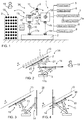
- Figure 1 shows in a highly simplified manner principle of a rock drilling unit 1 provided with an apparatus 36 for handling elongated drilling rods 2 or corresponding drilling components.
- the drilling unit 1 is supported on a base structure 3 by means of turning joints 4a and 4b so that position and orientation of the drilling unit 1 can be changed.
- the drilling unit 1 may comprise a feed beam 5, a feed device 6, a rock drilling machine 7, an alignment device 8 and a threading unit 9.
- the rock drilling machine 7 may be a rotating device 7a, which is configured to rotate drilling rods 2 and tools at a drilling center 10.
- the rock drilling machine 7 is supported on a feed beam 5 and is moved by means of the feed device 6.
- the alignment device 8 is located at a rear end portion of the rock drilling machine 7 and is configured to align new rods to be in with the drilling centre 10.
- the alignment device 8 may comprise transversally movable roller elements, for example.
- the threading device 9 may be located at a rear end portion of the feed beam 5 and is configured to rotate the rod in order to open and close screw joints between successive rods.
- a swing device 11 In connection with the drilling unit 1 is a swing device 11, which may be supported directly to the feed beam 5, or alternatively to a fastening beam 12, which is parallel to the feed beam 5. On both sides of the drilling unit 1 may be such fastening beams, whereby the swing device 12 may be mounted on either left or right side of the drilling unit 1.
- a rod feeder 13 may also be supported to the base structure 3.
- the rod feeder 13 is configured to move the rods between a pick-up position 14 and an intermediate position 15.
- gripping means of the rod feeder 13 are positioned to the intermediate position 15.
- the pick-up position 14 is located at rear area of the rod feeder and at lower vertical height.
- the rod feeder 13 comprises at least one arm 16, which is connected to the base structure 3 by means of a turning joint 17a for turning the arm 16 relative to the base structure 3.
- At a distal end portion of the arm 16 may be a turning joint 17b for turning a gripping device of the rod feeder 13 relative to the arm 16.
- Turning axis of the joints 4a, 4b, 17a and 17b may be transversal to the direction of the drilling center 10.
- the rods 2 may be stored to a rod storage 18.
- the rods 2 may be moved from the rod storage 18 to the pick-up position 14 manually by an operator 19 or there may be an industrial robot, a manipulator or any other device or mechanism for executing the transfer.
- the rod feeder 13 is configured to move the rod 2 from the pick-up position 14 to the intermediate position 15 wherefrom the rod is picked by the swing device 11.
- the swing device 11 comprises turning joints 20a, 20b allowing the swing device 11 to be turned in transverse direction relative to the drilling axis 10.
- the swing device 11 may move the rod 2 from the intermediate position 15 to the drilling axis 10 where it may be aligned and become connected to the previous rod.
- the drilling unit 1 provided with the swing device 11 and the rod feeder 13 are physically separate devices.
- the rod feeder 13 and the swing device 11 may be controlled separately.
- the control of the devices 1, 11 and 13 may be done under control of a control unit CU.
- the swing device 11 has gripped the rod 2 and begins to move it away from the intermediate position 15, the rod feeder 13 may instantly initiate new handling process for a next rod.
- Figure 2 discloses movements of a rod feeder 13.
- the rod feeder 13 comprises an arm 16, which may be extendable and may be connected to a base structure 3 by means of a turning joint 17a so that the rod feeder 13 may be turned on a vertical plane, which is parallel to a drilling centre 10 of a rock drilling unit 1. Thus, the rod feeder 13 may be moved back and forth and may be without any sideward movements.
- a gripping device 21 which may comprise an elongated frame 22 and two or more gripping elements 23, such as gripping jaws or rollers, for gripping a rod 2 at a longitudinal distance from each other.
- the gripping device 21 may be turned around a turning joint 17b so that orientation of the gripping device 21 may be adjusted.
- the rod feeder 13 may be positioned to an intermediate position 15 which is defined by the position and orientation of the drilling unit 1. And further, the rod feeder 13 may be positioned to a pick-up position 14 which may be located at rear of the drilling unit 1 and may have horizontal orientation and desired vertical height so that it is easy for an operator 19 to feed and remove rods. So, figure 2 discloses both the intermediate position 15 and the pick-up position 14.
- the rod feeder 13 may be substantially the same as in Figure 2 but now the pick-up position 14 has a vertical orientation at the rear area of the drilling unit. Further, in Figure 4 the pick-up position 14 also has a vertical orientation but is located at a frontal area of the drilling unit. As can be noted, the position and orientation of the pick-up position 14 may be adjusted according to personal demands of the operator and according to available free space around the drilling device. Safe areas for manual handling of the rods to and from the pick-up position 14 may be locate at front or rear areas relative to the drilling unit 1. The pick-up position 14 is reachable from vertical on rear side to vertical on front side. In Figures 2 - 4 drilling direction is indicated by a reference A.
- Figure 5 discloses a rod feeder 13 comprising two arm parts 16a, 16b connected to each other by means of a joint 17c.
- the arm 16 may be connected to a base structure by means of a turning support 24 so that the rod feeder 13 may also be turned laterally, whereby the configuration of the rod feeder 13 may resemble a robotic arm system or an industrial robot.
- the arm 16 may be arranged to be moved in one vertical plane in a similar manner as the embodiments shown in Figures 2 and 3 , and may thereby have simpler configuration and control.
- one or more arm parts 16a, 16b may comprise a zoom system for adjusting their lengths. In order to improve clarity turning actuators are not shown in Figures 1 - 5 .
- FIG. 6 is a highly simplified presentation of a swing device 11.
- the swing device 11 is configured to move the drilling rods 2 or other elongated drilling components between the intermediate position 15 of the gripping device 21 of the rod feeder and the drilling center 10 of the rock drilling machine 7.
- the swing device 11 may be mounted on the fastening beam 12 which is located on a side of the feed beam 5.
- the rock drilling machine 7 is mounted on a carriage 25, which is movable in longitudinal direction of the feed beam 5.
- the swing device 11 may comprise two arms 26 and 27 connected to each other by means of a turning joint 28 and connected to the fastening beam 12 by means of a turning joint 29.
- a gripping device 30 or gripper by means of which the swing device 11 may grip the rods 2.
- the gripping device is shown in a simplified manner.
- the swing device 11 is moved together with the feed beam 5 whereas the gripping device 21 of the rod feeder is not physically linked to the feed beam 5. Therefore, positioning measures are required to place the gripping system of the rod feeder 13 at a reach of the swing device 11 and to be parallel with the drilling centre 10 or line.
- Figure 7 discloses a rock drilling unit 1, which is provided with a swing device 11 and rod feeder 13 for moving rods 2 between a pick-up position 14 and a drilling center 10. Basic features of these devices have already been disclosed above. However, Figure 7 further discloses an actuator 31, such as a cylinder, for moving the feed beam 5, and an actuator 32, such as a cylinder, for moving the rod feeder 13 relative to the common base structure 3. The actuator 32 is shown in a simplified manner. At an extension of the rear end of the feed beam 5 is located movably the threading unit 9. The threading unit 9 may slide along a support beam portion 33 when being moved by means of an actuator 34, such as a cylinder. Figure 7 further shows that the alignment device 8 may be located at a rear end side of the rotating device 7a. The alignment device 8 and the rotating device 7a may both be supported on the carriage 25, which is moved by means of the feed device 6, such as a cylinder. At a front end of the feed beam 5 a front guide 35 for supporting the rod 2 may be arranged.
- FIGS 8 and 9 show the above disclosed apparatus in more detail and in two different view angles.
- Figure 10 illustrates transfer steps of drilling rods and components.
- the rods 2 are moved from a storage or storage position 36 to the pick-up position 14 either by the operator 19, manipulator or robot.
- the rods 2 may be moved from the pick-up position 14 to the intermediate position 15 by means of the rod feeder 13, and further be moved to the drilling centre 10 by means of the swing device 11.
- On the drilling centre 10 the rods 2 may be moved by means of the threading unit 9 and the feed device 6.
- the rods 2 are moved in an opposite direction, of course.
- Operation of the disclosed devices may be controlled by means of the control unit CU, which may comprise a processor, a software program and a memory device. Control parameters, programs and commands may be fed by means of an input device, and further, sensing data of sensors may be transmitted to the control unit.
- the control unit may generate control commands for actuators moving the disclosed devices independently for executing the needed handling processes.
Landscapes
- Engineering & Computer Science (AREA)
- Life Sciences & Earth Sciences (AREA)
- Geology (AREA)
- Mining & Mineral Resources (AREA)
- Mechanical Engineering (AREA)
- Physics & Mathematics (AREA)
- Environmental & Geological Engineering (AREA)
- Fluid Mechanics (AREA)
- General Life Sciences & Earth Sciences (AREA)
- Geochemistry & Mineralogy (AREA)
- Earth Drilling (AREA)
Abstract
Description
- The invention relates to an apparatus for handling rods in rock drilling and especially in core drilling.
- The invention further relates to a rock drilling unit and a method of handling rock drilling rods.
- The field of the invention is defined more specifically in the preambles of the independent claims.
- Core drilling is executed for investigating rock ground at a distance in order to determine conditions for extracting minerals. Thus, core drilling is used for exploration drilling purposes and construction work. During core drilling, aiming to extract a drill core, it is often drilled to very great depths and distances. As an example, it is common to drill holes over thousands of meters. During rock drilling of such long drill holes, it is necessary to join a plurality of drilling components such as drilling rods for forming a drill string. A drill bit, which is located at a distal end of the drill string, needs to be changed regularly, several times for every hole, typically after every 30 - 50 meters, which means that the entire drill string needs to be disassembled and assembled 15 - 20 times for each drill hole. Traditionally handling of the drilling components is done manually. Nowadays the core drilling devices are more and more provided with rod handling apparatuses for moving drilling rods and other drilling components between a pick-up position and a drilling center of the rock drilling machine. However, the known handling devices have shown to contain some disadvantages.
- An object of the invention is to provide a novel and improved apparatus for rod handling. The invention further relates to a novel and improved rock drilling unit and method of handling rods.
- The apparatus according to the invention is characterized by the characterizing features of first independent apparatus claim.
- The rock drilling unit according to the invention is characterized by the characterizing features of second independent apparatus claim.
- The method according to the invention is characterized by the charactering features and steps of independent method claim.
- An idea of the disclosed solution is that the rock drilling unit, which is intended especially for exploration drilling, may be provided with an apparatus for handling drilling rods and other elongated drilling components. The apparatus comprises a rod feeder for moving the drilling rods between a pick-up position and an intermediate position, and a swing device for moving the drilling rods between the intermediate position and a drilling center. The mentioned rod feeder and swing device are separate units so that they can be moved independently relative to each other. In other words, the rod feeder and the swing device are not integrated into one physical entity, but instead, they are separately operable devices.
- An advantage of the disclosed solution is that handling of the drilling rods may be quickened when the swing device and the rod feeder may be driven independently and may thereby execute handling tasks simultaneously. This way the drill string may be assembled and disassembled quicker than by using the known apparatuses.
- In this patent application the used terms drilling component and drilling rod include elongated drilling tools such as drilling tubes and solid rod type elements. The terms further include water swivel rods, inner tubes and retrieval elements, such as wire line retrieval tools, which are implemented in core and sample drilling.
- According to an embodiment, the swing device and the rod feeder comprise dedicated frames and dedicated actuators for executing their independent movements. Thanks to this, the swing device and the rod feeder may be mounted relatively freely relative to each other, which has positive impact on the layout of the drilling unit. A further advantage of the embodiment is that construction and operation of the dedicated devices may be designed according to their special needs.
- According to an embodiment, movement of the rod feeder has no influence to the swing device and correspondingly movement of the swing device has no influence to the rod feeder. Thus, the rod feeder and the swing device are separate units which can be moved independently.
- According to an embodiment, the rod feeder and the swing device are separate units without direct physical connection between them.
- According to an embodiment, direction of movements of the rod feeder and the swing device are transversal relative to each other.
- According to an embodiment, the rod feeder is configured to execute only turning movements. Thus, the rod feeder reciprocates only in one single movement direction.
- According to an embodiment, the drilling unit has a vertical first plane and the rod feeder has a vertical second plane. The second vertical plane of the rod feeder is configured to be constantly parallel relative to the first vertical plane during movement of the rod feeder.
- According to an embodiment, the rod feeder is configured to be turned relative to at least one first turning axis and the swing device is configured to be turned relative to at least one second turning axis. The first turning axis and the second turning axis are perpendicular relative to each other.
- According to an embodiment, the swing device has a fixed mounting and the only movement of the swing device is transversal turning movement relative to the drilling center.
- According to an embodiment, the rod feeder comprises at least two arms connected to each other by means of at least one connecting joint axis, which connecting joint is perpendicular to the drilling axis. A first arm is connected to a base structure of the drilling unit by means of a rotational joint axis, which is transversal to the drilling axis. At a distal end of a second arm is a gripping device or gripper, which may be turned relative to the second arm around a rotational joint axis, which is transversal to the drilling axis. Thus, the basic mechanism of the rod feeder may comprise two arms and three rotational joints, as well as actuators to carry out the movements.
- According to an embodiment, the rod feeder comprises at least one extendable arm for adjusting operative length of the device. In other words the rod feeder may comprise one linear joint enabling a so called zoom feature.
- According to an embodiment, location of the pick-up position is adjustable by adjusting movement control of the rod feeder. Mechanism of the rod feeder allows its gripping device to be driven in a versatile manner into desired position and height which is beneficial for effective and ergonomic handling.
- According to an embodiment, the apparatus is controlled by means of at least one control unit and the location of the pick-up position is programmable. The rod feeder may have a large reach area inside which one or more pick-up positions may be determined at desired locations. An advantage of this embodiment is that the position of the pick-up position may be selected by taking into account available free space around the drilling unit, location of a rod storage and desires of an operator. Height from the ground may also be determined and stored.
- According to an embodiment, orientation of the drilling component at the pick-up position is adjustable by adjusting movement control of the rod feeder whereby it is easy to take into account personal desires and ergonomic issues of different operators.
- According to an embodiment, the apparatus comprises one or more control units. Then, orientation of the drilling component at the pick-up position is controlled by means of the control unit. Thus, the desired orientation and exact position may be easily re-programmed. Alternatively, the desired positions and orientations of the pick-up positions may be taught and stored in a memory device. Updating of such programmed and taught pick-up positions is easy.
- According to an embodiment, the apparatus comprises at least one control unit which is configured to determine position and orientation of the intermediate position and the pick-up position. In other words, the intermediate position and the pick-up position are both imaginary positions which are not limited by means of any mechanical limiting elements. This way, the position and orientation are freely selectable. The control unit is configured to control the rod feeder to move between the defined intermediate position and pick-up position.
- According to an embodiment, the rock drilling unit comprises one or more sensors, scanners or corresponding measuring devices for sensing pose of the rock drilling unit. The sensing data is transmitted to at least one control unit, which is configured to determine position and orientation of the current position and is configured to determine position and orientation of the intermediate position on the basis of the detected position and orientation in order to carry out transport of the rods between the intermediate position and the drilling axis.
- According to an embodiment, one drill rod may be hold at the intermediate position by means of the rod feeder while the swing device is handling another drill rod. This way the swing device may be operable with a rod while a gripping device of the rod feeder is occupied by another rod. Thus, the rod feeder may provide the apparatus with an intermediate storage.
- According to an embodiment, the rod feeder is configured to receive and supply the drilling rod at the pick-up position in horizontal or substantially horizontal orientation. This embodiment may be implemented for example when the drilling rods are stored on horizontal racks or supports.
- According to an embodiment, the rod feeder is configured to receive and supply the drilling rod at the pick-up position in vertical or substantially vertical orientation. In narrow mine spaces it may be easier to store and handle the drilling components which are orientated vertically. The drilling components may also be stored in vertical direction inside a rod storage.
- According to an embodiment, between the intermediate position and the pick-up position is a horizontal distance when viewed in the direction of the drilling center, whereby the pick-up position is located horizontally at rearward end portion of the drilling unit.
- According to an embodiment, the rod feeder and the swing device are both provided with at least one dedicated gripper for gripping the rods.
- According to an embodiment, each of the dedicated grippers of the rod feeder and the swing device comprise at least two jaws, which are located at a distance from each other when seen in longitudinal direction of the drilling component being handled.
- According to an embodiment, the swing device may comprise grippers which are based on roller-like gripping elements. These elements may be an alternative solution to jaw-like grippers. The roller-like gripping elements may be not only moved relative to each other but also be rotated so that they may also be enabled in threading of the drilling components. In that case, the roller-like gripping elements may serve as an integrated threading unit whereby no separate threading unit elsewhere in the drilling unit is needed. An advantage of such a combination swing device is that the apparatus has fewer devices, may be smaller in size and also lighter in weight.
- According to an embodiment, the rod feeder may be configured to serve as an intermediate rod storage at the intermediate position. Then one rod may be stored on the dedicated grippers of the rod feeder. This way, the rod feeder may bring the next drilling component to the intermediate rod storage, wherein it may wait for the swing device to become vacant.
- According to an embodiment, the rod feeder is mountable on either longitudinal side of the rock drilling unit. An advantage of this embodiment is that the same construction may be used for right- and left-hand implementations, whereby need for two different rod feeders with different handedness is not needed. In other words, the rod feeder may have a symmetrical structure, whereby it may be a more universal and versatile device. The same applies also for the swing device, which may have a symmetrical structure so that it may be mounted on either sides of the feed beam.
- According to an embodiment, the swing device is supported to the drilling unit and the rod feeder is supported directly to the base structure. The apparatus may comprise one common base structure, or alternatively, dedicated base structures for drilling unit and the rod feeder. The base structure may be designed to be supported against the ground and may comprise a frame structure made of steel bars or tubes, for example.
- According to an embodiment, the swing device is mounted to a slide element so that it may be moved in longitudinal direction of the feed beam. The mentioned slide element may be supported directly to the feed beam or to an additional fastening beam mounted to the feed beam and being parallel to the feed beam. The longitudinal movement of the slide element and the swing device may be synchronized to longitudinal movements of the threading unit.
- According to an embodiment, the swing device is mounted longitudinally immovably to the feed beam of the drilling unit or to an additional fastening beam mounted to the feed beam and being parallel to the feed beam. This way the mounting may be firm and the structure of the mounting may be simple.
- According to an embodiment, directions of movement paths of the rod feeder and the swing device are transverse relative to each other. The rod feeder is arranged to be moved predominantly in front - rear direction whereas the swing device is arranged to move predominantly in transverse direction. Thus, the basic movements of the devices are easy to handle and no complicated joints and movement control are needed. The simple movements may be fast, which has positive impact on effectivity.
- According to an embodiment, the rod feeder and the swing device have both only one dedicated function and they are separately controllable units. Thus, the rod feeder and the swing device may be devices which are designed for special purposes without any need for compromises. This way their effectivity and durability, for example, may be improved.
- According to an embodiment, the rock drilling unit comprises at least one control unit. The control unit is configured to control the rod handling apparatus to move according to its work cycle simultaneously and independently relative to the operation of the threading unit. This way the threading unit and the rod handling apparatus may be driven simultaneously, which increases the performance of the handling of the drilling components. The control unit may comprise a processor which is configured to execute a software designed to control the operation of the apparatus. The control device may be located in connection to the apparatus or it may be located externally of the apparatus.
- According to an embodiment, the rod feeder is an independently movable device, which is movable simultaneously with the swing device. The ability for simultaneous movements of these two devices has a significant impact on improved efficiency for the rod handling procedure. In other words, multitasking of the co-operating rod feeder and the swing device quickens loading and removing drilling components to and from the drill string.
- According to an embodiment, the apparatus comprises a control unit which is configured to control the rod handling device, the threading device and the alignment device to perform multiple operational functions at the same time.
- According to an embodiment, the threading unit is located at an extension of the feed beam. An advantage of this embodiment is that at the rear end of the feed beam may be an extension part, which offers proper support for the threading unit. A further advantage is that at the rear of the feed beam there is sufficiently free space for arranging the threading unit and it does not cause any visibility problem to an operator.
- According to an embodiment, the threading unit is integrated in the swing device. Means for executing threading may be combined with gripping means of the swing device or they may be arranged separately in connection to the swing device.
- According to an embodiment, the rod handling apparatus is configured to co-operate with at least one rod manipulator for feeding drilling rods automatically from a rod storage to the pick-up position and correspondingly for removing the rods from the pick-up position automatically to the rod storage. The rod manipulator may comprise an articulated arm system or it may be an industrial robot. Alternatively, or in addition to, the rod manipulator may comprise one or more transport tracks for moving the drilling rods and components. The rod storage may be a separate mobile unit, which may be positioned at a drilling site, or alternatively, the storage may be a separate unit being integrated to be part of the rock drilling unit. The rod storage may be dimensioned to receive dozens of drilling components, and typically up to 100 - 200 components, sometimes even more than 350 components.
- According to an embodiment, the rock drilling machine of the drilling unit is a rotation device or a rotation head. Thus, the rod handling apparatus is implemented in rotational drilling.
- Let it be mentioned, that regarding the steps of handling the elongated drilling components, such as drilling rods, it is assumed in this patent application that one or several drilling rods have already been drilled into the rock and the last rod, which is partly drilled into the rock, is penetrating through the rock drilling machine so that a rearward end of the partly drilled rod is exposed. The solution disclosed in this patent application is for adding or removing drilling rods to a drill rod string comprising several drilling rods.
- The above disclosed embodiments may be combined in order to form suitable solutions having those of the above features that are needed.
- Some embodiments are described in more detail in the accompanying drawings, in which
-
Figure 1 is a schematic view of a rock drilling unit provided with an apparatus for handling elongated drilling tools, -
Figure 2 is a schematic view of a rod feeder arranged to turn around turning axis and configured to transfer drilling components from a horizontal pick-up position to an intermediate position adjacent to a feed beam of a rock drilling unit, -
Figure 3 is a schematic view of a rod feeder provided with a vertical pick-up position which is located at rear side area of the drilling unit, -
Figure 4 is a schematic view of a rod feeder provided with a vertical pick-up position which is located at front side area of the drilling unit, -
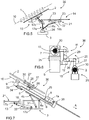
Figure 5 is a schematic view of a rod feeder configuration of which is an articulated boom comprising several arms and joints, -
Figure 6 is a schematic view of a swing device configured to move drilling components between an intermediate position of a rod feeder to a drilling center of a rock drilling machine, -
Figure 7 is a schematic side view of a rock drilling unit provided with an apparatus for handling drilling components; -
Figures 8 and 9 are schematic views of a rock drilling unit provided with an apparatus for handling drilling components; and -
Figure 10 is a schematic diagram showing transfer steps of drilling rods and means for executing the movements. - For the sake of clarity, the figures show some embodiments of the disclosed solution in a simplified manner. In the figures, like reference numerals identify like elements.
-
Figure 1 shows in a highly simplified manner principle of arock drilling unit 1 provided with anapparatus 36 for handlingelongated drilling rods 2 or corresponding drilling components. Thedrilling unit 1 is supported on abase structure 3 by means of turningjoints drilling unit 1 can be changed. Thedrilling unit 1 may comprise afeed beam 5, afeed device 6, arock drilling machine 7, analignment device 8 and athreading unit 9. Therock drilling machine 7 may be arotating device 7a, which is configured to rotatedrilling rods 2 and tools at adrilling center 10. Therock drilling machine 7 is supported on afeed beam 5 and is moved by means of thefeed device 6. Thealignment device 8 is located at a rear end portion of therock drilling machine 7 and is configured to align new rods to be in with thedrilling centre 10. Thealignment device 8 may comprise transversally movable roller elements, for example. Thethreading device 9 may be located at a rear end portion of thefeed beam 5 and is configured to rotate the rod in order to open and close screw joints between successive rods. - In connection with the
drilling unit 1 is aswing device 11, which may be supported directly to thefeed beam 5, or alternatively to afastening beam 12, which is parallel to thefeed beam 5. On both sides of thedrilling unit 1 may be such fastening beams, whereby theswing device 12 may be mounted on either left or right side of thedrilling unit 1. - A
rod feeder 13 may also be supported to thebase structure 3. Therod feeder 13 is configured to move the rods between a pick-upposition 14 and anintermediate position 15. InFigure 1 gripping means of therod feeder 13 are positioned to theintermediate position 15. The pick-upposition 14 is located at rear area of the rod feeder and at lower vertical height. Therod feeder 13 comprises at least onearm 16, which is connected to thebase structure 3 by means of a turning joint 17a for turning thearm 16 relative to thebase structure 3. At a distal end portion of thearm 16 may be a turning joint 17b for turning a gripping device of therod feeder 13 relative to thearm 16. Turning axis of thejoints drilling center 10. - The
rods 2 may be stored to arod storage 18. Therods 2 may be moved from therod storage 18 to the pick-upposition 14 manually by anoperator 19 or there may be an industrial robot, a manipulator or any other device or mechanism for executing the transfer. - The
rod feeder 13 is configured to move therod 2 from the pick-upposition 14 to theintermediate position 15 wherefrom the rod is picked by theswing device 11. Theswing device 11 comprises turningjoints 20a, 20b allowing theswing device 11 to be turned in transverse direction relative to thedrilling axis 10. Theswing device 11 may move therod 2 from theintermediate position 15 to thedrilling axis 10 where it may be aligned and become connected to the previous rod. As can be noted, thedrilling unit 1 provided with theswing device 11 and therod feeder 13 are physically separate devices. Moreover, therod feeder 13 and theswing device 11 may be controlled separately. The control of thedevices swing device 11 has gripped therod 2 and begins to move it away from theintermediate position 15, therod feeder 13 may instantly initiate new handling process for a next rod. -
Figure 2 discloses movements of arod feeder 13. Therod feeder 13 comprises anarm 16, which may be extendable and may be connected to abase structure 3 by means of a turning joint 17a so that therod feeder 13 may be turned on a vertical plane, which is parallel to adrilling centre 10 of arock drilling unit 1. Thus, therod feeder 13 may be moved back and forth and may be without any sideward movements. At a distal end of thearm 16 is agripping device 21, which may comprise anelongated frame 22 and two or moregripping elements 23, such as gripping jaws or rollers, for gripping arod 2 at a longitudinal distance from each other. Thegripping device 21 may be turned around a turning joint 17b so that orientation of thegripping device 21 may be adjusted. Thereby, therod feeder 13 may be positioned to anintermediate position 15 which is defined by the position and orientation of thedrilling unit 1. And further, therod feeder 13 may be positioned to a pick-upposition 14 which may be located at rear of thedrilling unit 1 and may have horizontal orientation and desired vertical height so that it is easy for anoperator 19 to feed and remove rods. So,figure 2 discloses both theintermediate position 15 and the pick-upposition 14. - In
Figure 3 therod feeder 13 may be substantially the same as inFigure 2 but now the pick-upposition 14 has a vertical orientation at the rear area of the drilling unit. Further, inFigure 4 the pick-upposition 14 also has a vertical orientation but is located at a frontal area of the drilling unit. As can be noted, the position and orientation of the pick-upposition 14 may be adjusted according to personal demands of the operator and according to available free space around the drilling device. Safe areas for manual handling of the rods to and from the pick-upposition 14 may be locate at front or rear areas relative to thedrilling unit 1. The pick-upposition 14 is reachable from vertical on rear side to vertical on front side. InFigures 2 - 4 drilling direction is indicated by a reference A. -
Figure 5 discloses arod feeder 13 comprising twoarm parts arm 16 may be connected to a base structure by means of a turningsupport 24 so that therod feeder 13 may also be turned laterally, whereby the configuration of therod feeder 13 may resemble a robotic arm system or an industrial robot. Alternatively, thearm 16 may be arranged to be moved in one vertical plane in a similar manner as the embodiments shown inFigures 2 and 3 , and may thereby have simpler configuration and control. Further, one ormore arm parts Figures 1 - 5 . -
Figure 6 is a highly simplified presentation of aswing device 11. As it is mentioned above, theswing device 11 is configured to move thedrilling rods 2 or other elongated drilling components between theintermediate position 15 of thegripping device 21 of the rod feeder and thedrilling center 10 of therock drilling machine 7. Theswing device 11 may be mounted on thefastening beam 12 which is located on a side of thefeed beam 5. Therock drilling machine 7 is mounted on acarriage 25, which is movable in longitudinal direction of thefeed beam 5. Theswing device 11 may comprise twoarms fastening beam 12 by means of a turning joint 29. At a distal end of the arm system is agripping device 30 or gripper, by means of which theswing device 11 may grip therods 2. For clarity reasons the gripping device is shown in a simplified manner. As can be noted, theswing device 11 is moved together with thefeed beam 5 whereas thegripping device 21 of the rod feeder is not physically linked to thefeed beam 5. Therefore, positioning measures are required to place the gripping system of therod feeder 13 at a reach of theswing device 11 and to be parallel with thedrilling centre 10 or line. -
Figure 7 discloses arock drilling unit 1, which is provided with aswing device 11 androd feeder 13 for movingrods 2 between a pick-upposition 14 and adrilling center 10. Basic features of these devices have already been disclosed above. However,Figure 7 further discloses anactuator 31, such as a cylinder, for moving thefeed beam 5, and anactuator 32, such as a cylinder, for moving therod feeder 13 relative to thecommon base structure 3. Theactuator 32 is shown in a simplified manner. At an extension of the rear end of thefeed beam 5 is located movably thethreading unit 9. Thethreading unit 9 may slide along asupport beam portion 33 when being moved by means of anactuator 34, such as a cylinder.Figure 7 further shows that thealignment device 8 may be located at a rear end side of therotating device 7a. Thealignment device 8 and therotating device 7a may both be supported on thecarriage 25, which is moved by means of thefeed device 6, such as a cylinder. At a front end of the feed beam 5 afront guide 35 for supporting therod 2 may be arranged. -
Figures 8 and 9 show the above disclosed apparatus in more detail and in two different view angles. -
Figure 10 illustrates transfer steps of drilling rods and components. Therods 2 are moved from a storage orstorage position 36 to the pick-upposition 14 either by theoperator 19, manipulator or robot. Therods 2 may be moved from the pick-upposition 14 to theintermediate position 15 by means of therod feeder 13, and further be moved to thedrilling centre 10 by means of theswing device 11. On thedrilling centre 10 therods 2 may be moved by means of thethreading unit 9 and thefeed device 6. When the drill string is disassembled then therods 2 are moved in an opposite direction, of course. Operation of the disclosed devices may be controlled by means of the control unit CU, which may comprise a processor, a software program and a memory device. Control parameters, programs and commands may be fed by means of an input device, and further, sensing data of sensors may be transmitted to the control unit. The control unit may generate control commands for actuators moving the disclosed devices independently for executing the needed handling processes. - The drawings and the related description are only intended to illustrate the idea of the invention. In its details, the invention may vary within the scope of the claims.
Claims (15)
- An apparatus (36) for rod handling, which is mountable in connection to a rock drilling unit (1) and wherein the apparatus (36) is configured to move rock drilling rods (2) between at least one pick-up position (14) and a drilling center (10) of the rock drilling unit (1);
the apparatus (36) comprising:a rod feeder (13) for moving the drilling rods (2) between the pick-up position (14) and an intermediate position (15),a swing device (11) for moving the drilling rods (2) between the intermediate position (15) and the drilling center (10); andat least one gripper for gripping the rods (2);characterized in thatthe rod feeder (13) and the swing device (11) are separate units, which are movable independently relative to each other. - The apparatus as claimed in claim 1, characterized in that
direction of movements of the rod feeder (13) and the swing device (11) are transversal relative to each other. - The apparatus as claimed in claim 1 or 2, characterized in that
the swing device (11) has a fixed mounting and the only movement of the swing device (11) is transversal turning movement relative to the drilling center (10). - The apparatus as claimed in any one of the previous claims 1 to 3, characterized in that
the rod feeder (13) comprises at least two arms (16a, 16b) connected to each other by means of at least one connecting joint (17c) axis of which connecting joint is perpendicular to the drilling axis (10). - The apparatus as claimed in any one of the preceding claims 1 to 4, characterized in that
location of the pick-up position (14) is adjustable by adjusting movement control of the rod feeder (13). - The apparatus as claimed in any one of the preceding claims 1 - 5, characterized in that
the rod feeder (13) and the swing device (11) are both provided with at least one dedicated gripper (21, 30) for gripping the rods (2). - The apparatus as claimed in any one of the preceding claims 1 - 6, characterized in that
the apparatus (36) is mountable on either longitudinal side of the rock drilling unit (1). - A rock drilling unit (1), comprising:a feed beam (5);a rock drilling machine (7) supported on the feed beam (5) and comprising at least a rotating device (7a) for rotating drilling rods (2);a feed device (6) for moving the rock drilling machine (7) longitudinally on the feed beam (5);an alignment device (8) for aligning a new rod (2) on the drilling center (10) with a previous rod (2) passing through the rock drilling machine (7);a threading unit (9) arranged to be movable on the drilling center (10) and configured to rotate the new rod and to simultaneously feed the new rod relative to the previous rod;an apparatus (36) for rod handling, wherein the apparatus (36) is configured to move the rods (2) between at least one pick-up position (14) and the drilling center (10), and wherein the apparatus (36) comprises a rod feeder (13) and a swing device (11);and wherein the rock drilling unit (1) is supported to a base structure (3);characterized in thatthe apparatus (36) for rod handling is according to any one of the preceding claims 1 to 7; and furtherthe swing device (11) is supported to the drilling unit (1) and the rod feeder (13) is supported directly to the base structure (3).
- The rock drilling unit according to claim 8, characterized in that
the apparatus (36) comprises at least one control unit (CU); and
the control unit (CU) is configured to control the rod handling apparatus (36) to move according to its work cycle simultaneously and independently relative to the operation of the threading unit (9). - The rock drilling unit according to claim 8 or 9, characterized in that
the apparatus (36) comprises at least one control unit (CU);
the control unit (CU) is configured to determine position and orientation of the intermediate position (15) and the pick- up position (14), which are both imaginary positions without being mechanically limited; and
the control unit (CU) is configured to control the rod feeder (13) to move between the determined intermediate position (15) and pick-up position (14). - The rock drilling unit according any one of the preceding claims 8 - 10, characterized in that
the threading unit (9) is located at an extension of the feed beam (5). - The rock drilling unit according to any one of the preceding claims 8 to 11, characterized in that
the rod handling apparatus (36) is configured to co-operate with at least one rod manipulator for feeding drilling rods (2) automatically from a rod storage (18) to the pick-up position (14) and correspondingly for removing the rods (2) from the pick-up position (14) automatically to the rod storage (18). - A method of handling drilling rods in core drilling wherein drill holes are drilled by means of a rock drilling unit (1) comprising a feed beam (5) and a rock drilling machine (7),
the method comprising:moving the rods (2) between at least one pick-up position (14) and an intermediate position (15) by means of a rod feeder (13);moving the rods (2) between the intermediate position (15) and a drilling center (10) defined by the rock drilling machine (7) by means of a swing device (11); andmoving the swing device (11) and the rod feeder (13) along movement paths which are transversal relative to each other;characterized byusing in rod handling physically and operationally separate devices as the swing device (11) and the rod feeder (13);and moving the swing device (11) and the rod feeder (13) simultaneously and independently along their transversal movement paths. - The method according to claim 13, characterized by
detecting position and orientation of the rock drilling unit (1) by means of at least one sensing device; and
determining position and orientation of the intermediate position (14) on the basis of the detected position and orientation of the rock drilling unit (1). - The method according to claim 13 or 14, characterized by
holding one drill rod (2) at the intermediate position (15) by means of the rod feeder (13) while the swing device (11) is handling another drill rod (2).
Priority Applications (9)
| Application Number | Priority Date | Filing Date | Title |
|---|---|---|---|
| EP18154331.5A EP3521550B1 (en) | 2018-01-31 | 2018-01-31 | Apparatus for rod handling, rock drilling unit and method |
| FIEP18154331.5T FI3521550T3 (en) | 2018-01-31 | 2018-01-31 | Apparatus for rod handling, rock drilling unit and method |
| RU2020125167A RU2020125167A (en) | 2018-01-31 | 2019-01-24 | ROD MANIPULATION DEVICE, DRILLING UNIT AND METHOD |
| AU2019215678A AU2019215678A1 (en) | 2018-01-31 | 2019-01-24 | Apparatus for rod handling, rock drilling unit and method |
| US16/965,879 US20210115737A1 (en) | 2018-01-31 | 2019-01-24 | Apparatus for rock handling, rock drilling unit and method |
| PCT/EP2019/051734 WO2019149613A1 (en) | 2018-01-31 | 2019-01-24 | Apparatus for rock handling, rock drilling unit and method |
| CA3089927A CA3089927A1 (en) | 2018-01-31 | 2019-01-24 | Apparatus for rod handling, rock drilling unit and method |
| CN201980010864.2A CN111655963A (en) | 2018-01-31 | 2019-01-24 | Apparatus, rock drilling unit and method for rock handling |
| CL2020001973A CL2020001973A1 (en) | 2018-01-31 | 2020-07-28 | Rod handling apparatus, rock drilling unit and method. |
Applications Claiming Priority (1)
| Application Number | Priority Date | Filing Date | Title |
|---|---|---|---|
| EP18154331.5A EP3521550B1 (en) | 2018-01-31 | 2018-01-31 | Apparatus for rod handling, rock drilling unit and method |
Publications (2)
| Publication Number | Publication Date |
|---|---|
| EP3521550A1 true EP3521550A1 (en) | 2019-08-07 |
| EP3521550B1 EP3521550B1 (en) | 2022-10-26 |
Family
ID=61132096
Family Applications (1)
| Application Number | Title | Priority Date | Filing Date |
|---|---|---|---|
| EP18154331.5A Active EP3521550B1 (en) | 2018-01-31 | 2018-01-31 | Apparatus for rod handling, rock drilling unit and method |
Country Status (9)
| Country | Link |
|---|---|
| US (1) | US20210115737A1 (en) |
| EP (1) | EP3521550B1 (en) |
| CN (1) | CN111655963A (en) |
| AU (1) | AU2019215678A1 (en) |
| CA (1) | CA3089927A1 (en) |
| CL (1) | CL2020001973A1 (en) |
| FI (1) | FI3521550T3 (en) |
| RU (1) | RU2020125167A (en) |
| WO (1) | WO2019149613A1 (en) |
Families Citing this family (3)
| Publication number | Priority date | Publication date | Assignee | Title |
|---|---|---|---|---|
| WO2022119455A1 (en) * | 2020-12-03 | 2022-06-09 | Coremax Limited | A core sample handling device |
| EP4095346B1 (en) * | 2021-05-27 | 2024-07-31 | Sandvik Mining and Construction Oy | Undergroung drilling rig tramming control |
| WO2026076528A1 (en) * | 2024-10-08 | 2026-04-16 | Services de Forage Orbit Garant Inc. | Rod feeding apparatus in core drilling |
Citations (5)
| Publication number | Priority date | Publication date | Assignee | Title |
|---|---|---|---|---|
| US20010020550A1 (en) * | 2000-03-08 | 2001-09-13 | Casagrande Spa | Automatic loader for drill rods |
| EP2799661A2 (en) * | 2013-04-30 | 2014-11-05 | Arctic Drilling Company Oy Ltd | Automatic drill rod handling |
| WO2016167636A1 (en) * | 2015-04-17 | 2016-10-20 | 인석신 | Rod mounting device for boring machine |
| EP3181803A1 (en) * | 2015-12-18 | 2017-06-21 | Sandvik Mining and Construction Oy | Drill rod changer, rock drilling unit and method of changing drill rods |
| WO2017185164A1 (en) * | 2016-04-25 | 2017-11-02 | Martin Doyon | Rod handling system |
Family Cites Families (4)
| Publication number | Priority date | Publication date | Assignee | Title |
|---|---|---|---|---|
| US20100307826A1 (en) * | 2009-06-03 | 2010-12-09 | Bucyrus Mining Equipment, Inc. | Rod changer for a rock drill |
| EP2765272A1 (en) * | 2013-02-08 | 2014-08-13 | Sandvik Mining and Construction Oy | Rock drilling unit and method of changing drill rods |
| WO2015024001A1 (en) * | 2013-08-15 | 2015-02-19 | Sharewell Hdd Drilling Products, Llc | Universal pipe dispatch for drill pipe joints |
| SE538847C2 (en) * | 2015-01-19 | 2017-01-03 | Atlas Copco Rock Drills Ab | Positioning arrangement, rod handling device, drill rig and method for positioning of a drill rod |
-
2018
- 2018-01-31 EP EP18154331.5A patent/EP3521550B1/en active Active
- 2018-01-31 FI FIEP18154331.5T patent/FI3521550T3/en active
-
2019
- 2019-01-24 US US16/965,879 patent/US20210115737A1/en not_active Abandoned
- 2019-01-24 RU RU2020125167A patent/RU2020125167A/en unknown
- 2019-01-24 CA CA3089927A patent/CA3089927A1/en active Pending
- 2019-01-24 CN CN201980010864.2A patent/CN111655963A/en active Pending
- 2019-01-24 WO PCT/EP2019/051734 patent/WO2019149613A1/en not_active Ceased
- 2019-01-24 AU AU2019215678A patent/AU2019215678A1/en not_active Abandoned
-
2020
- 2020-07-28 CL CL2020001973A patent/CL2020001973A1/en unknown
Patent Citations (5)
| Publication number | Priority date | Publication date | Assignee | Title |
|---|---|---|---|---|
| US20010020550A1 (en) * | 2000-03-08 | 2001-09-13 | Casagrande Spa | Automatic loader for drill rods |
| EP2799661A2 (en) * | 2013-04-30 | 2014-11-05 | Arctic Drilling Company Oy Ltd | Automatic drill rod handling |
| WO2016167636A1 (en) * | 2015-04-17 | 2016-10-20 | 인석신 | Rod mounting device for boring machine |
| EP3181803A1 (en) * | 2015-12-18 | 2017-06-21 | Sandvik Mining and Construction Oy | Drill rod changer, rock drilling unit and method of changing drill rods |
| WO2017185164A1 (en) * | 2016-04-25 | 2017-11-02 | Martin Doyon | Rod handling system |
Also Published As
| Publication number | Publication date |
|---|---|
| RU2020125167A (en) | 2022-02-28 |
| CA3089927A1 (en) | 2019-08-08 |
| RU2020125167A3 (en) | 2022-03-18 |
| FI3521550T3 (en) | 2023-01-31 |
| EP3521550B1 (en) | 2022-10-26 |
| WO2019149613A1 (en) | 2019-08-08 |
| US20210115737A1 (en) | 2021-04-22 |
| CN111655963A (en) | 2020-09-11 |
| AU2019215678A1 (en) | 2020-08-20 |
| CL2020001973A1 (en) | 2021-04-16 |
Similar Documents
| Publication | Publication Date | Title |
|---|---|---|
| US9540891B2 (en) | Device and method for handling drill string components and drill rig | |
| US20210115737A1 (en) | Apparatus for rock handling, rock drilling unit and method | |
| US9428971B2 (en) | Rock drilling unit and method of changing drill rods | |
| CN101903614B (en) | Method and devices for handling rod-like pieces in drilling and bolting | |
| US20070234775A1 (en) | Bending machine for rod-shaped workpieces made from wire, tubular material or the like | |
| FI110805B (en) | Arrangements for replacing a drilling component in a rock drilling device | |
| CN108943000B (en) | Workpiece clamping device | |
| RU2707839C2 (en) | System for installation of consumable part for underground drilling | |
| CN111822969B (en) | Hydraulic cylinder through hole identification and adjustment device, method and automatic assembly system | |
| CN104806277A (en) | Automatic rod feeding device for mine anchor rod drilling machine | |
| JP6675377B2 (en) | Ground excavation method using robot arm | |
| JPH1158327A (en) | Race charger | |
| KR20150091820A (en) | Machine tool | |
| CN115637939B (en) | Drill jumbo rod replacing device, drill jumbo and rod loading and unloading method | |
| CN111561265A (en) | Rock drilling device, rock drilling rig and drilling method | |
| CN214520192U (en) | Rotary flange unit is snatched with truss manipulator to curved after welding | |
| JP6667159B2 (en) | Component removal positioning device | |
| CN209009533U (en) | Assemble device | |
| RU2849873C1 (en) | Loading and unloading device for drilling rig rods and drilling rig | |
| RU233315U1 (en) | DRILL ROD CASSETTE | |
| JP2563610Y2 (en) | Material feeder in section steel processing machine | |
| KR20260052757A (en) | Bending machine and bending method for a rod-shaped workpiece made of solid or tubular material | |
| AU2024357317A1 (en) | Rock drilling rig and method of handling drill bits | |
| RU2020135060A (en) | DRILLING MACHINE FOR SETTING ANCHOR SUPPORT AND METHOD FOR SETTING ANCHOR SUPPORT WITH A DRILLING MACHINE | |
| CN120619658A (en) | Intelligent spiral roller tooth holder welding method |
Legal Events
| Date | Code | Title | Description |
|---|---|---|---|
| PUAI | Public reference made under article 153(3) epc to a published international application that has entered the european phase |
Free format text: ORIGINAL CODE: 0009012 |
|
| STAA | Information on the status of an ep patent application or granted ep patent |
Free format text: STATUS: THE APPLICATION HAS BEEN PUBLISHED |
|
| AK | Designated contracting states |
Kind code of ref document: A1 Designated state(s): AL AT BE BG CH CY CZ DE DK EE ES FI FR GB GR HR HU IE IS IT LI LT LU LV MC MK MT NL NO PL PT RO RS SE SI SK SM TR |
|
| AX | Request for extension of the european patent |
Extension state: BA ME |
|
| STAA | Information on the status of an ep patent application or granted ep patent |
Free format text: STATUS: REQUEST FOR EXAMINATION WAS MADE |
|
| 17P | Request for examination filed |
Effective date: 20200207 |
|
| RBV | Designated contracting states (corrected) |
Designated state(s): AL AT BE BG CH CY CZ DE DK EE ES FI FR GB GR HR HU IE IS IT LI LT LU LV MC MK MT NL NO PL PT RO RS SE SI SK SM TR |
|
| STAA | Information on the status of an ep patent application or granted ep patent |
Free format text: STATUS: EXAMINATION IS IN PROGRESS |
|
| 17Q | First examination report despatched |
Effective date: 20200420 |
|
| GRAP | Despatch of communication of intention to grant a patent |
Free format text: ORIGINAL CODE: EPIDOSNIGR1 |
|
| STAA | Information on the status of an ep patent application or granted ep patent |
Free format text: STATUS: GRANT OF PATENT IS INTENDED |
|
| INTG | Intention to grant announced |
Effective date: 20220811 |
|
| RIN1 | Information on inventor provided before grant (corrected) |
Inventor name: TOIVOLA, JUHA Inventor name: JELGERT, JOHAN Inventor name: FREDIN, OLA Inventor name: BENGTSSON, STEFAN Inventor name: LAHDELMA, ILKKA |
|
| GRAS | Grant fee paid |
Free format text: ORIGINAL CODE: EPIDOSNIGR3 |
|
| GRAA | (expected) grant |
Free format text: ORIGINAL CODE: 0009210 |
|
| STAA | Information on the status of an ep patent application or granted ep patent |
Free format text: STATUS: THE PATENT HAS BEEN GRANTED |
|
| AK | Designated contracting states |
Kind code of ref document: B1 Designated state(s): AL AT BE BG CH CY CZ DE DK EE ES FI FR GB GR HR HU IE IS IT LI LT LU LV MC MK MT NL NO PL PT RO RS SE SI SK SM TR |
|
| REG | Reference to a national code |
Ref country code: GB Ref legal event code: FG4D |
|
| REG | Reference to a national code |
Ref country code: CH Ref legal event code: EP |
|
| REG | Reference to a national code |
Ref country code: AT Ref legal event code: REF Ref document number: 1527145 Country of ref document: AT Kind code of ref document: T Effective date: 20221115 |
|
| REG | Reference to a national code |
Ref country code: DE Ref legal event code: R096 Ref document number: 602018042143 Country of ref document: DE |
|
| REG | Reference to a national code |
Ref country code: IE Ref legal event code: FG4D |
|
| REG | Reference to a national code |
Ref country code: FI Ref legal event code: FGE |
|
| REG | Reference to a national code |
Ref country code: SE Ref legal event code: TRGR |
|
| REG | Reference to a national code |
Ref country code: LT Ref legal event code: MG9D |
|
| REG | Reference to a national code |
Ref country code: NL Ref legal event code: MP Effective date: 20221026 |
|
| REG | Reference to a national code |
Ref country code: NO Ref legal event code: T2 Effective date: 20221026 |
|
| REG | Reference to a national code |
Ref country code: AT Ref legal event code: MK05 Ref document number: 1527145 Country of ref document: AT Kind code of ref document: T Effective date: 20221026 |
|
| PG25 | Lapsed in a contracting state [announced via postgrant information from national office to epo] |
Ref country code: NL Free format text: LAPSE BECAUSE OF FAILURE TO SUBMIT A TRANSLATION OF THE DESCRIPTION OR TO PAY THE FEE WITHIN THE PRESCRIBED TIME-LIMIT Effective date: 20221026 |
|
| PG25 | Lapsed in a contracting state [announced via postgrant information from national office to epo] |
Ref country code: PT Free format text: LAPSE BECAUSE OF FAILURE TO SUBMIT A TRANSLATION OF THE DESCRIPTION OR TO PAY THE FEE WITHIN THE PRESCRIBED TIME-LIMIT Effective date: 20230227 Ref country code: LT Free format text: LAPSE BECAUSE OF FAILURE TO SUBMIT A TRANSLATION OF THE DESCRIPTION OR TO PAY THE FEE WITHIN THE PRESCRIBED TIME-LIMIT Effective date: 20221026 Ref country code: ES Free format text: LAPSE BECAUSE OF FAILURE TO SUBMIT A TRANSLATION OF THE DESCRIPTION OR TO PAY THE FEE WITHIN THE PRESCRIBED TIME-LIMIT Effective date: 20221026 Ref country code: AT Free format text: LAPSE BECAUSE OF FAILURE TO SUBMIT A TRANSLATION OF THE DESCRIPTION OR TO PAY THE FEE WITHIN THE PRESCRIBED TIME-LIMIT Effective date: 20221026 |
|
| PG25 | Lapsed in a contracting state [announced via postgrant information from national office to epo] |
Ref country code: RS Free format text: LAPSE BECAUSE OF FAILURE TO SUBMIT A TRANSLATION OF THE DESCRIPTION OR TO PAY THE FEE WITHIN THE PRESCRIBED TIME-LIMIT Effective date: 20221026 Ref country code: PL Free format text: LAPSE BECAUSE OF FAILURE TO SUBMIT A TRANSLATION OF THE DESCRIPTION OR TO PAY THE FEE WITHIN THE PRESCRIBED TIME-LIMIT Effective date: 20221026 Ref country code: LV Free format text: LAPSE BECAUSE OF FAILURE TO SUBMIT A TRANSLATION OF THE DESCRIPTION OR TO PAY THE FEE WITHIN THE PRESCRIBED TIME-LIMIT Effective date: 20221026 Ref country code: IS Free format text: LAPSE BECAUSE OF FAILURE TO SUBMIT A TRANSLATION OF THE DESCRIPTION OR TO PAY THE FEE WITHIN THE PRESCRIBED TIME-LIMIT Effective date: 20230226 Ref country code: HR Free format text: LAPSE BECAUSE OF FAILURE TO SUBMIT A TRANSLATION OF THE DESCRIPTION OR TO PAY THE FEE WITHIN THE PRESCRIBED TIME-LIMIT Effective date: 20221026 Ref country code: GR Free format text: LAPSE BECAUSE OF FAILURE TO SUBMIT A TRANSLATION OF THE DESCRIPTION OR TO PAY THE FEE WITHIN THE PRESCRIBED TIME-LIMIT Effective date: 20230127 |
|
| PGFP | Annual fee paid to national office [announced via postgrant information from national office to epo] |
Ref country code: TR Payment date: 20230126 Year of fee payment: 6 |
|
| REG | Reference to a national code |
Ref country code: DE Ref legal event code: R097 Ref document number: 602018042143 Country of ref document: DE |
|
| PG25 | Lapsed in a contracting state [announced via postgrant information from national office to epo] |
Ref country code: SM Free format text: LAPSE BECAUSE OF FAILURE TO SUBMIT A TRANSLATION OF THE DESCRIPTION OR TO PAY THE FEE WITHIN THE PRESCRIBED TIME-LIMIT Effective date: 20221026 Ref country code: RO Free format text: LAPSE BECAUSE OF FAILURE TO SUBMIT A TRANSLATION OF THE DESCRIPTION OR TO PAY THE FEE WITHIN THE PRESCRIBED TIME-LIMIT Effective date: 20221026 Ref country code: EE Free format text: LAPSE BECAUSE OF FAILURE TO SUBMIT A TRANSLATION OF THE DESCRIPTION OR TO PAY THE FEE WITHIN THE PRESCRIBED TIME-LIMIT Effective date: 20221026 Ref country code: DK Free format text: LAPSE BECAUSE OF FAILURE TO SUBMIT A TRANSLATION OF THE DESCRIPTION OR TO PAY THE FEE WITHIN THE PRESCRIBED TIME-LIMIT Effective date: 20221026 Ref country code: CZ Free format text: LAPSE BECAUSE OF FAILURE TO SUBMIT A TRANSLATION OF THE DESCRIPTION OR TO PAY THE FEE WITHIN THE PRESCRIBED TIME-LIMIT Effective date: 20221026 |
|
| PG25 | Lapsed in a contracting state [announced via postgrant information from national office to epo] |
Ref country code: SK Free format text: LAPSE BECAUSE OF FAILURE TO SUBMIT A TRANSLATION OF THE DESCRIPTION OR TO PAY THE FEE WITHIN THE PRESCRIBED TIME-LIMIT Effective date: 20221026 Ref country code: AL Free format text: LAPSE BECAUSE OF FAILURE TO SUBMIT A TRANSLATION OF THE DESCRIPTION OR TO PAY THE FEE WITHIN THE PRESCRIBED TIME-LIMIT Effective date: 20221026 |
|
| REG | Reference to a national code |
Ref country code: CH Ref legal event code: PL |
|
| PLBE | No opposition filed within time limit |
Free format text: ORIGINAL CODE: 0009261 |
|
| STAA | Information on the status of an ep patent application or granted ep patent |
Free format text: STATUS: NO OPPOSITION FILED WITHIN TIME LIMIT |
|
| GBPC | Gb: european patent ceased through non-payment of renewal fee |
Effective date: 20230131 |
|
| PG25 | Lapsed in a contracting state [announced via postgrant information from national office to epo] |
Ref country code: LU Free format text: LAPSE BECAUSE OF NON-PAYMENT OF DUE FEES Effective date: 20230131 |
|
| REG | Reference to a national code |
Ref country code: BE Ref legal event code: MM Effective date: 20230131 |
|
| 26N | No opposition filed |
Effective date: 20230727 |
|
| PG25 | Lapsed in a contracting state [announced via postgrant information from national office to epo] |
Ref country code: LI Free format text: LAPSE BECAUSE OF NON-PAYMENT OF DUE FEES Effective date: 20230131 Ref country code: GB Free format text: LAPSE BECAUSE OF NON-PAYMENT OF DUE FEES Effective date: 20230131 Ref country code: CH Free format text: LAPSE BECAUSE OF NON-PAYMENT OF DUE FEES Effective date: 20230131 |
|
| PG25 | Lapsed in a contracting state [announced via postgrant information from national office to epo] |
Ref country code: SI Free format text: LAPSE BECAUSE OF FAILURE TO SUBMIT A TRANSLATION OF THE DESCRIPTION OR TO PAY THE FEE WITHIN THE PRESCRIBED TIME-LIMIT Effective date: 20221026 Ref country code: BE Free format text: LAPSE BECAUSE OF NON-PAYMENT OF DUE FEES Effective date: 20230131 |
|
| PG25 | Lapsed in a contracting state [announced via postgrant information from national office to epo] |
Ref country code: IE Free format text: LAPSE BECAUSE OF NON-PAYMENT OF DUE FEES Effective date: 20230131 |
|
| PGFP | Annual fee paid to national office [announced via postgrant information from national office to epo] |
Ref country code: SE Payment date: 20231213 Year of fee payment: 7 Ref country code: FR Payment date: 20231222 Year of fee payment: 7 Ref country code: FI Payment date: 20231219 Year of fee payment: 7 |
|
| PGFP | Annual fee paid to national office [announced via postgrant information from national office to epo] |
Ref country code: DE Payment date: 20231205 Year of fee payment: 7 |
|
| PG25 | Lapsed in a contracting state [announced via postgrant information from national office to epo] |
Ref country code: IT Free format text: LAPSE BECAUSE OF FAILURE TO SUBMIT A TRANSLATION OF THE DESCRIPTION OR TO PAY THE FEE WITHIN THE PRESCRIBED TIME-LIMIT Effective date: 20221026 |
|
| PGFP | Annual fee paid to national office [announced via postgrant information from national office to epo] |
Ref country code: NO Payment date: 20240108 Year of fee payment: 7 |
|
| PG25 | Lapsed in a contracting state [announced via postgrant information from national office to epo] |
Ref country code: MC Free format text: LAPSE BECAUSE OF FAILURE TO SUBMIT A TRANSLATION OF THE DESCRIPTION OR TO PAY THE FEE WITHIN THE PRESCRIBED TIME-LIMIT Effective date: 20221026 |
|
| PG25 | Lapsed in a contracting state [announced via postgrant information from national office to epo] |
Ref country code: MC Free format text: LAPSE BECAUSE OF FAILURE TO SUBMIT A TRANSLATION OF THE DESCRIPTION OR TO PAY THE FEE WITHIN THE PRESCRIBED TIME-LIMIT Effective date: 20221026 |
|
| PG25 | Lapsed in a contracting state [announced via postgrant information from national office to epo] |
Ref country code: BG Free format text: LAPSE BECAUSE OF FAILURE TO SUBMIT A TRANSLATION OF THE DESCRIPTION OR TO PAY THE FEE WITHIN THE PRESCRIBED TIME-LIMIT Effective date: 20221026 |
|
| PG25 | Lapsed in a contracting state [announced via postgrant information from national office to epo] |
Ref country code: BG Free format text: LAPSE BECAUSE OF FAILURE TO SUBMIT A TRANSLATION OF THE DESCRIPTION OR TO PAY THE FEE WITHIN THE PRESCRIBED TIME-LIMIT Effective date: 20221026 |
|
| PG25 | Lapsed in a contracting state [announced via postgrant information from national office to epo] |
Ref country code: CY Free format text: LAPSE BECAUSE OF FAILURE TO SUBMIT A TRANSLATION OF THE DESCRIPTION OR TO PAY THE FEE WITHIN THE PRESCRIBED TIME-LIMIT; INVALID AB INITIO Effective date: 20180131 |
|
| REG | Reference to a national code |
Ref country code: DE Ref legal event code: R119 Ref document number: 602018042143 Country of ref document: DE |
|
| PG25 | Lapsed in a contracting state [announced via postgrant information from national office to epo] |
Ref country code: HU Free format text: LAPSE BECAUSE OF FAILURE TO SUBMIT A TRANSLATION OF THE DESCRIPTION OR TO PAY THE FEE WITHIN THE PRESCRIBED TIME-LIMIT; INVALID AB INITIO Effective date: 20180131 |
|
| REG | Reference to a national code |
Ref country code: SE Ref legal event code: EUG |
|
| PG25 | Lapsed in a contracting state [announced via postgrant information from national office to epo] |
Ref country code: DE Free format text: LAPSE BECAUSE OF NON-PAYMENT OF DUE FEES Effective date: 20250801 Ref country code: FI Free format text: LAPSE BECAUSE OF NON-PAYMENT OF DUE FEES Effective date: 20250131 |
|
| PG25 | Lapsed in a contracting state [announced via postgrant information from national office to epo] |
Ref country code: NO Free format text: LAPSE BECAUSE OF NON-PAYMENT OF DUE FEES Effective date: 20250131 |
|
| PG25 | Lapsed in a contracting state [announced via postgrant information from national office to epo] |
Ref country code: FR Free format text: LAPSE BECAUSE OF NON-PAYMENT OF DUE FEES Effective date: 20250131 |
|
| PG25 | Lapsed in a contracting state [announced via postgrant information from national office to epo] |
Ref country code: TR Free format text: LAPSE BECAUSE OF NON-PAYMENT OF DUE FEES Effective date: 20240131 |
|
| PG25 | Lapsed in a contracting state [announced via postgrant information from national office to epo] |
Ref country code: MT Free format text: LAPSE BECAUSE OF NON-PAYMENT OF DUE FEES Effective date: 20230131 |