EP3521191A1 - Refill container - Google Patents
Refill container Download PDFInfo
- Publication number
- EP3521191A1 EP3521191A1 EP17856019.9A EP17856019A EP3521191A1 EP 3521191 A1 EP3521191 A1 EP 3521191A1 EP 17856019 A EP17856019 A EP 17856019A EP 3521191 A1 EP3521191 A1 EP 3521191A1
- Authority
- EP
- European Patent Office
- Prior art keywords
- inner container
- lid member
- container
- accommodation
- refillable
- Prior art date
- Legal status (The legal status is an assumption and is not a legal conclusion. Google has not performed a legal analysis and makes no representation as to the accuracy of the status listed.)
- Pending
Links
Images












Classifications
-
- B—PERFORMING OPERATIONS; TRANSPORTING
- B65—CONVEYING; PACKING; STORING; HANDLING THIN OR FILAMENTARY MATERIAL
- B65D—CONTAINERS FOR STORAGE OR TRANSPORT OF ARTICLES OR MATERIALS, e.g. BAGS, BARRELS, BOTTLES, BOXES, CANS, CARTONS, CRATES, DRUMS, JARS, TANKS, HOPPERS, FORWARDING CONTAINERS; ACCESSORIES, CLOSURES, OR FITTINGS THEREFOR; PACKAGING ELEMENTS; PACKAGES
- B65D77/00—Packages formed by enclosing articles or materials in preformed containers, e.g. boxes, cartons, sacks or bags
- B65D77/04—Articles or materials enclosed in two or more containers disposed one within another
- B65D77/0446—Articles or materials enclosed in two or more containers disposed one within another the inner and outer containers being rigid or semi-rigid and the outer container being of polygonal cross-section not formed by folding or erecting one or more blanks
- B65D77/0453—Articles or materials enclosed in two or more containers disposed one within another the inner and outer containers being rigid or semi-rigid and the outer container being of polygonal cross-section not formed by folding or erecting one or more blanks the inner container having a polygonal cross-section
-
- B—PERFORMING OPERATIONS; TRANSPORTING
- B05—SPRAYING OR ATOMISING IN GENERAL; APPLYING FLUENT MATERIALS TO SURFACES, IN GENERAL
- B05B—SPRAYING APPARATUS; ATOMISING APPARATUS; NOZZLES
- B05B11/00—Single-unit hand-held apparatus in which flow of contents is produced by the muscular force of the operator at the moment of use
- B05B11/0005—Components or details
- B05B11/0037—Containers
- B05B11/0054—Cartridges, i.e. containers specially designed for easy attachment to or easy removal from the rest of the sprayer
-
- B—PERFORMING OPERATIONS; TRANSPORTING
- B05—SPRAYING OR ATOMISING IN GENERAL; APPLYING FLUENT MATERIALS TO SURFACES, IN GENERAL
- B05B—SPRAYING APPARATUS; ATOMISING APPARATUS; NOZZLES
- B05B11/00—Single-unit hand-held apparatus in which flow of contents is produced by the muscular force of the operator at the moment of use
- B05B11/0005—Components or details
- B05B11/0037—Containers
- B05B11/0038—Inner container disposed in an outer shell or outer casing
-
- B—PERFORMING OPERATIONS; TRANSPORTING
- B65—CONVEYING; PACKING; STORING; HANDLING THIN OR FILAMENTARY MATERIAL
- B65D—CONTAINERS FOR STORAGE OR TRANSPORT OF ARTICLES OR MATERIALS, e.g. BAGS, BARRELS, BOTTLES, BOXES, CANS, CARTONS, CRATES, DRUMS, JARS, TANKS, HOPPERS, FORWARDING CONTAINERS; ACCESSORIES, CLOSURES, OR FITTINGS THEREFOR; PACKAGING ELEMENTS; PACKAGES
- B65D21/00—Nestable, stackable or joinable containers; Containers of variable capacity
- B65D21/08—Containers of variable capacity
- B65D21/086—Collapsible or telescopic containers
-
- B—PERFORMING OPERATIONS; TRANSPORTING
- B65—CONVEYING; PACKING; STORING; HANDLING THIN OR FILAMENTARY MATERIAL
- B65D—CONTAINERS FOR STORAGE OR TRANSPORT OF ARTICLES OR MATERIALS, e.g. BAGS, BARRELS, BOTTLES, BOXES, CANS, CARTONS, CRATES, DRUMS, JARS, TANKS, HOPPERS, FORWARDING CONTAINERS; ACCESSORIES, CLOSURES, OR FITTINGS THEREFOR; PACKAGING ELEMENTS; PACKAGES
- B65D25/00—Details of other kinds or types of rigid or semi-rigid containers
- B65D25/20—External fittings
-
- B—PERFORMING OPERATIONS; TRANSPORTING
- B65—CONVEYING; PACKING; STORING; HANDLING THIN OR FILAMENTARY MATERIAL
- B65D—CONTAINERS FOR STORAGE OR TRANSPORT OF ARTICLES OR MATERIALS, e.g. BAGS, BARRELS, BOTTLES, BOXES, CANS, CARTONS, CRATES, DRUMS, JARS, TANKS, HOPPERS, FORWARDING CONTAINERS; ACCESSORIES, CLOSURES, OR FITTINGS THEREFOR; PACKAGING ELEMENTS; PACKAGES
- B65D5/00—Rigid or semi-rigid containers of polygonal cross-section, e.g. boxes, cartons or trays, formed by folding or erecting one or more blanks made of paper
- B65D5/40—Rigid or semi-rigid containers of polygonal cross-section, e.g. boxes, cartons or trays, formed by folding or erecting one or more blanks made of paper specially constructed to contain liquids
-
- B—PERFORMING OPERATIONS; TRANSPORTING
- B65—CONVEYING; PACKING; STORING; HANDLING THIN OR FILAMENTARY MATERIAL
- B65D—CONTAINERS FOR STORAGE OR TRANSPORT OF ARTICLES OR MATERIALS, e.g. BAGS, BARRELS, BOTTLES, BOXES, CANS, CARTONS, CRATES, DRUMS, JARS, TANKS, HOPPERS, FORWARDING CONTAINERS; ACCESSORIES, CLOSURES, OR FITTINGS THEREFOR; PACKAGING ELEMENTS; PACKAGES
- B65D77/00—Packages formed by enclosing articles or materials in preformed containers, e.g. boxes, cartons, sacks or bags
- B65D77/04—Articles or materials enclosed in two or more containers disposed one within another
- B65D77/06—Liquids or semi-liquids or other materials or articles enclosed in flexible containers disposed within rigid containers
- B65D77/062—Flexible containers disposed within polygonal containers formed by folding a carton blank
- B65D77/068—Spouts formed separately from the container
-
- B—PERFORMING OPERATIONS; TRANSPORTING
- B65—CONVEYING; PACKING; STORING; HANDLING THIN OR FILAMENTARY MATERIAL
- B65D—CONTAINERS FOR STORAGE OR TRANSPORT OF ARTICLES OR MATERIALS, e.g. BAGS, BARRELS, BOTTLES, BOXES, CANS, CARTONS, CRATES, DRUMS, JARS, TANKS, HOPPERS, FORWARDING CONTAINERS; ACCESSORIES, CLOSURES, OR FITTINGS THEREFOR; PACKAGING ELEMENTS; PACKAGES
- B65D83/00—Containers or packages with special means for dispensing contents
-
- B—PERFORMING OPERATIONS; TRANSPORTING
- B05—SPRAYING OR ATOMISING IN GENERAL; APPLYING FLUENT MATERIALS TO SURFACES, IN GENERAL
- B05B—SPRAYING APPARATUS; ATOMISING APPARATUS; NOZZLES
- B05B15/00—Details of spraying plant or spraying apparatus not otherwise provided for; Accessories
- B05B15/30—Dip tubes
Definitions
- the present invention relates to a refillable container which can be refilled with a liquid content such as cosmetics and detergents.
- a refillable container which can be refilled with a liquid content such as cosmetics and detergents
- a liquid content such as cosmetics and detergents
- a refillable container including: an inner container configured to contain a content and be replaced when the content has been exhausted; an accommodation member, which has an accommodation opening, and is configured to accommodate the inner container; a cylindrical lid member fitted to the accommodation member accommodating the inner container to close the accommodation member; and a taking-out part configured to take out the content contained in the inner container accommodated in the accommodation member (see, for example, Patent Literatures 1 and 2).
- Refilling is performed with the refillable containers described in Patent Literatures 1 and 2 in the following manner.
- the lid member is removed from the accommodation member, and the inner container is taken out from the accommodation member. Then, the inner container is replaced with a new inner container.
- an inner container configured to contain a content is formed into a shape having a size which is suitable to be accommodated in an accommodation member in a state in which a gap with the accommodation member is small so as to prevent the accommodation member from becoming larger more than necessary. Therefore, it is troublesome to perform an operation of taking out the inner container in which a liquid content has been exhausted from the accommodation member.
- a container main body serving as an inner container has a neck portion, and the neck portion has a mouth portion.
- the inner container can be easily taken out from the accommodation member by holding the neck portion.
- a mouth plug is mounted so as to protrude on a flat upper surface of an inner container.
- the inner container can be easily taken out from an accommodation member by holding the mouth plug.
- the inner container can be easily taken out from the accommodation member by holding the neck portion formed in the inner container with the refillable container described in Patent Literature 1, or by holding and pulling up the mouth plug mounted to the flat upper surface of the inner container with the refillable container as described in Patent Literature 2.
- the neck portion formed in the inner container or the mouth plug mounted to the flat upper surface of the inner container creates a needless space in the accommodation member configured to accommodate the inner container. Therefore, there arises a problem in that the accommodation member becomes larger more than necessary.
- An object of the present invention is to provide a refillable container which allows an inner container to be easily taken out from an accommodation member so as to enable an operation of refilling a content through replacement of the inner container to be easily performed, and which enables reduction in size of the accommodation member configured to accommodate the inner container.
- a refillable container including: an inner container configured to contain a content and be replaced when the content has been exhausted; an accommodation member, which has an accommodation opening, and is configured to accommodate the inner container; a cylindrical lid member, which is to be fitted to the accommodation member accommodating the inner container, and is configured to close the accommodation member; a taking-out part configured to take out the content contained in the inner container accommodated in the accommodation member; and an inner-container restraint part, which is provided between the lid member and the inner container, is configured to restrain the lid member and the inner container so as to prevent the inner container from falling from an opening portion of the lid member by its own weight when the lid member is removed from the accommodation member, and is configured to release the restraint between the lid member and the inner container when the inner container in which the content has been exhausted is pulled from the opening portion of the lid member in a pull-out direction.
- the inner container accommodated in the lid member is taken out from the accommodation member integrally with the lid member through intermediation of the inner-container restraint part. Accordingly, even when the opening portion of the lid member is oriented downward, the inner container is prevented from falling from the lid member. Then, the inner container in which the content has been exhausted can be reliably pulled out from the opening portion of the lid member.
- the inner-container restraint part includes: a protruding step portion provided on an upper outer surface of a body of the inner container; and a protruding portion provided on an inner surface of a cylindrical wall portion which is fitted to an outer periphery of the accommodation member of the lid member. At a time of an operation of closing the accommodation member by the lid member, the protruding portion rides over the protruding step portion provided on the upper outer surface of the inner container accommodated in the accommodation member.
- the protruding portion engages with a lower side of the protruding step portion so as to restrain the inner container and prevent the inner container from falling from the opening portion of the lid member by its own weight, and the restraint is released by pulling the inner container from the opening portion of the lid member so that the protruding step portion rides over the protruding portion.
- the protruding portion provided on the inner surface of the cylindrical wall portion of the lid member engages with the lower side of the protruding step portion provided on the inner container accommodated in the accommodation member, and the inner container is taken out from inside the accommodation member integrally with the lid member, and the inner container is prevented from falling from the lid member even when the opening portion of the lid member is oriented downward.
- the protruding step portion rides over the protruding portion, and hence the inner container can be reliably pulled out from the opening portion of the lid member.
- the protruding step portion provided on the upper outer surface of the body of the inner container is provided at an upper end edge portion of the body.
- the protruding portion provided on the inner surface of the cylindrical wall portion of the lid member engages with the lower side of the protruding step portion provided on the upper end edge of the body of the inner container accommodated in the accommodation member so that the inner container is taken out from the accommodation member integrally with the lid member.
- the protruding step portion provided on the upper outer surface of the body of the inner container is provided on an outer peripheral surface of the body.
- the protruding portion provided on the inner surface of the cylindrical wall portion of the lid member engages with the lower side of the protruding step portion provided on the outer peripheral surface of the body of the inner container accommodated in the accommodation member so that the inner container is taken out from the accommodation member integrally with the lid member.
- the inner-container restraint part is provided on one or both of an inner surface of a cylindrical wall portion of the lid member and an outer surface of a body of the inner container, and is formed of a contact portion configured to make the inner surface of the cylindrical wall portion of the lid member come into contact with the outer surface of the body of the inner container.
- a resistance force of the contact portion at a time of pulling out the inner container from an opening portion of the lid member is represented by X1
- a lower limit resistance force to prevent the inner content from falling from the opening portion of the lid member by its own weight is represented by X2
- an upper limit resistance force capable of pulling out the inner container accommodated in the lid member from the opening portion of the lid member in a state in which the content has been exhausted is represented by X3
- the resistance force X1 given at the time of pulling out the inner container accommodated in the lid member from the opening portion of the lid member is set within a range defined by X2 ⁇ X1 ⁇ X3.
- X2 ⁇ X1 ⁇ X3 is set, and hence, when the lid member is removed from the accommodation member accommodating the inner container, the inner container accommodated in the lid member is taken out from the accommodation member integrally with the lid member, and even when the opening portion of the lid member is oriented downward, the inner container is prevented from falling from the lid member. Then, the inner container in which the content has been exhausted can be pulled out reliably from the opening portion of the lid member.
- the lower limit resistance force X2 is calculated with the inner container in a state in which the content has been exhausted.
- the lower limit resistance force X2 is calculated with the inner container in a state in which the content has been exhausted, and hence, when the lid is removed from the accommodation member after the content has been exhausted, the inner container is prevented from falling from inside the lid member by its own weight, and the inner container accommodated in the lid member is reliably taken out from the accommodation member integrally with the lid member.
- the lower limit resistance force X2 is calculated with the inner container in a state in which the content is fully contained.
- the lower limit resistance force X2 is calculated with the inner container in a state in which the content is fully contained, and hence, when the lid member is removed from the accommodation member in the state in which the content is fully contained in the inner container, the inner container is prevented from falling from inside the lid member by its own weight, and the inner container accommodated in the lid member can be taken out reliably from the accommodation member integrally with the lid member.
- the upper limit resistance force X3 is calculated as a resistance force capable of pulling out the inner container from the opening portion of the lid member without difficulty in a state in which the content contained in the inner container accommodated in the lid member has been exhausted.
- the upper limit resistance force X3 is calculated as a resistance force capable of pulling out the inner container from the opening portion of the lid member without difficulty in the state in which the content contained in the inner container accommodated in the lid member has been exhausted, and hence the inner container in which the content has been exhausted can be easily and reliably pulled out from the opening portion of the lid member.
- the inner container accommodated in the accommodation member can be taken out from the accommodation member integrally with the lid member, and the inner container in which a content has been exhausted can be pulled out from an opening of the lid member. Accordingly, the operation of refilling the content through replacement of the inner container can be easily performed.
- the inner container is not required to have a protruding portion such as a mouth plug also serving as a holding portion at the time of taking out from the accommodation member on the upper surface, and thereby a needless space in the accommodation member accommodating the inner container is eliminated and the accommodation member can be reduced in size by the amount corresponding to the needless space.
- a protruding portion such as a mouth plug also serving as a holding portion at the time of taking out from the accommodation member on the upper surface
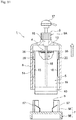
- FIG. 1 to FIG. 10 are views for illustrating a first example of a refillable container according to an embodiment of the present invention.
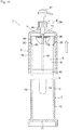
- FIG. 1 is an exploded sectional view of the refillable container of this example.
- FIG. 2 is a perspective view for illustrating an inner container in the refillable container illustrated in FIG. 1 .
- FIG. 3 is a sectional view taken along a line A-A of FIG. 2 .
- FIG. 4 is a developed view for illustrating a carton blank before an assembly process of the inner container illustrated in FIG. 2 .
- FIG. 5 is an explanatory view for illustrating a step of forming an upper surface of the inner container illustrated in FIG. 2 .
- FIG. 6 is an explanatory view for illustrating a step of forming the upper surface of the inner container illustrated in FIG.
- FIG. 7 is a sectional view for illustrating a process of closing an accommodation member accommodating the inner container by a lid member in the refillable container illustrated in FIG. 1 .
- FIG. 8 is a sectional view for illustrating a state in which the accommodation member accommodating the inner container is closed by the lid member in the refillable container illustrated in FIG. 1 .
- FIG. 9 is a sectional view for illustrating a state in which the lid member is removed from the accommodation member accommodating the inner container in the refillable container illustrated in FIG. 1 .
- FIG. 10 is a sectional view for illustrating a state in which the lid member has been removed from the accommodation member accommodating the inner container in the refillable container illustrated in FIG. 1 .
- a refillable container 1 of the first example includes an inner container 5, an accommodation member 7, a cylindrical lid member 8, a taking-out part 9, and an inner-container restraint part 59.
- the inner container 5 has a suction port 4, which is formed on an upper surface 2 and is sealed with a tearable sealing sheet 3.
- the inner container 5 is configured to contain a liquid content, and is replaced when the content has been exhausted.
- the accommodation member 7 has an accommodation opening 6 at an upper portion, and is configured to accommodate the inner container 5.
- the cylindrical lid member 8 is to be fitted to the accommodation member 7 accommodating the inner container 5, and is configured to close the accommodation member 7.
- the taking-out part 9 is configured to take out the content contained in the inner container 5 accommodated in the accommodation member 7.
- the inner-container restraint part 59 is provided between the lid member 8 and the inner container 5.
- the inner-container restraint part 59 is configured to restrain the lid member 8 and the inner container 5 so as to prevent the inner container 5 from falling from an opening portion of the lid member 8 by its own weight when the lid member 8 is removed from the accommodation member 7.
- the inner-container restraint part 59 is configured to release the restraint between the lid member 8 and the inner container 5 when the inner container 5 in which the content has been exhausted is pulled from the opening portion 62 of the lid member 8 in a pull-out direction.
- a shape of the accommodation member 7 is not particularly limited as long as the accommodation member 7 can secure the inner container 5.
- the accommodation member 7 of the first example is a cylindrical accommodation container 10 having the accommodation opening 6 at an upper portion.
- the accommodation container 10 is formed to have a shape corresponding to an outer shape of the inner container 5, and a cross-sectional shape of a body is a substantially square cylindrical shape in the first example.
- a length of the accommodation container 10 is such that, when the inner container 5 is accommodated in the accommodation container 10, an end surface of the accommodation opening 6 of the accommodation container 10 is flush with an upper surface 2 of the inner container 5 or slightly exceeds the upper surface 2 of the inner container 5.
- the accommodation container 10 is formed to have a length slightly exceeding the upper surface 2 of the inner container 5.
- the accommodation container 10 is formed with cutout portions 12 extending from the accommodation opening 6 to a bottom portion 11 side so as not to disturb movement of protruding portions formed on an inner surface of a cylindrical wall portion of the lid member 8 described later.
- the lid member 8 of the first example includes a top plate portion 13 and a cylindrical wall portion 14.
- the top plate portion 13 is configured to close the accommodation opening 6 of the accommodation container 10.
- the cylindrical wall portion 14 is fitted to an outer periphery of the accommodation container 10.
- taking-out part 9 configured to take out the content contained in the inner container 5 accommodated in the accommodation member 7.
- the taking-out part 9 of the first example is a discharge pump 9A which includes a tubular cylinder portion 16, a discharge nozzle 17, and a suction tube 18.
- the discharge nozzle 17 is provided at an upper portion of the tubular cylinder portion 16, and serves as an operation portion of a piston freely fitted to be slidable in the tubular cylinder portion 16.
- the suction tube 18 is provided at a lower portion of the tubular cylinder portion 16.
- the discharge pump 9A serving as the taking-out part 9 thus configured is, in the first example, mounted to the lid member 8. Specifically, the tubular cylinder portion 16 penetrates the top plate portion 13 of the lid member 8 to be secured.
- the discharge nozzle 17 is arranged on an upper surface side of the top plate portion 13.
- the suction tube 18 is arranged on a lower surface side of the top plate portion 13.
- the inner container 5 of the first example has a body 19 having a substantially square shape in cross section, and is shaped to be accommodated in a state in which there is almost no space in the accommodation container 10.
- the inner container 5 of the present example is made of a paper material formed with a resin layer on at least one side thereof, has four body panels 24, 25, 26, and 27 via body longitudinal folding lines 21, 22, and 23, and includes the body 19 formed into a rectangular tubular shape in which an edge portion of the body panel 24 is joined by a longitudinal seal panel 29 which is connected consecutively to the body panel 27 via a seal longitudinal folding line 28.
- the upper surface 2 of the inner container 1 is configured as described below.
- a pair of side panels 35 and 36 are continuously provided on upper edges of the body panels 25 and 26 through top horizontal folding lines 37 and 38.
- the pair of side panels 35 and 36 are positioned between the above-mentioned pair of upper-surface forming panels 32 and 33 to face each other and folded up along with overlapping of the pair of upper-surface forming panels 32 and 33.
- holes 39a and 39b are formed at centers of the upper-surface forming panels 32 and 33, respectively, to serve as a suction port 4.
- the holes 39a and 39b are opened so that a center of the hole 39a and a center of the hole 39b match with each other when the upper-surface forming panels 32 and 33 overlap.
- a sealing sheet 3, which is tearable, is provided on a back surface of the upper-surface forming panel 33 so as to seal the hole 39b.
- a suction tube 18 of the discharge pump 9A forming the taking-out part 9 is stuck into the sealing sheet 3 so as to tear the film 3.
- the sealing sheet 3 may be pasted on a back surface of an upper-surface forming panel 33, or may be formed integrally with a laminated product which is laminated on the paper material formed with the resin layer forming the inner container 5. Further, the sealing sheet 3 is not particularly limited to the material and the configuration described above as long as the sealing sheet 3 is impermeable and tearable. As the sealing sheet 3, a resin film, a metal foil, a sheet of paper, or a laminated body thereof is exemplified.
- the upper surface 2 of the inner container 5 is formed by the upper-surface forming panels 32 and 33 and the side panels 35 and 36 as described below.
- the upper-surface forming panel 33 is folded inwardly.
- the side panels 35 and 36 are folded up to inner surface sides into a triangular shape, and an upper accommodation opening of the body 19 is closed by the upper-surface forming panel 33.
- the sealing panel 34 which is continuously provided on the upper edge of the upper-surface forming panel 33, is bonded to the inner surface of the upper-surface forming panel 32 in an area of S1 so as to seal the inner container 1.
- Both side edges of the upper-surface forming panel 33 are bonded to the side panels 35 and 36, which have been folded up into a triangular shape, in an area of S2 so as to seal the inner container 1 (see FIG. 5 ).
- the side panels 35 and 36 are folded up outwardly (in directions indicated by the arrows in FIG. 5 ) so that the upper-surface forming panel 32 overlies the upper-surface forming panel 33 (see FIG. 6 ).
- the side panels 35 and 36 which have been folded up to protrude to an outside of the body 19, are folded downwardly (in directions indicated by the arrows in FIG. 6 ), and fixed to the body 11 with an adhesive or the like. Accordingly, the upper surface 2 is formed.
- the side panels 35 and 36 secured to the body 19 form protruding step portions 20 described later as the inner-container restraint part 59.
- the bottom surface 40 of the inner container 5 is configured as described below.
- a pair of gable roof-shaped bottom surface forming panels 43 and 44, which face each other, are continuously provided on lower edges of the body panels 24 and 26 through bottom horizontal folding lines 41 and 42.
- Outer sealing panels 45 and 46, which have a belt-like shape, are continuously provided on lower parts of the gable roof-shaped bottom surface forming panels 43 and 44.
- a pair of gable wall-shaped bottom surface forming panels 49 and 50 which face each other, are continuously provided on lower edges of the body panels 25 and 27 through bottom horizontal folding lines 47 and 48.
- Inner sealing panels 51 and 52 which have a belt-like shape and a height smaller than that of the outer sealing panels 45 and 46, are continuously provided on lower parts of the gable wall-shaped bottom surface forming panels 49 and 50.
- the bottom surface 40 is formed by the gable roof-shaped bottom surface forming panels 43 and 44 and the gable wall-shaped bottom surface forming panels 49 and 50 as described below.
- the gable wall-shaped bottom surface forming panels 49 and 50 are folded in between the gable roof-shaped bottom surface forming panels 43 and 44, and facing surfaces of the outer sealing panels 45 and 46, which face each other, are bonded to each other to seal the inner container 1. Further, facing surfaces of the outer sealing panels 45 and 46 and facing surfaces of the inner sealing panels 51 and 52, and facing surfaces of the inner sealing panels 51 and 52 are bonded to each other to seal the inner container 1. Accordingly, the bottom surface 40 is formed into a reversed quadrangular pyramid shape of a so-called reversed gable top shape (see FIG. 2 and FIG. 3 ).
- the inner-container restraint part 59 includes the protruding step portions 20 provided on an upper outer surface of the body 19 of the inner container 5 and protruding portions 15 provided on an inner surface of the cylindrical wall portion 14 of the lid member 8.
- the protruding portions 15 provided on the inner surface of the cylindrical wall portion 14 of the lid member 8 are configured as follows. At the time of an operation of closing the accommodation container 10 by the lid member 8, the protruding portions 15 ride over the protruding step portions 20 provided on the upper outer periphery of the inner container 5 accommodated in the accommodation container 10. At the time of an operation of removing the lid member 8 from the accommodation container 10, the protruding portions 15 engage with lower sides of the protruding step portions 20 so as to restrain the inner container 5 and prevent the inner container 5 from falling from the opening portion 62 of the lid member 8 by its own weight, and the protruding step portions 20 can ride over the protruding portions 15 by pulling the inner container 5 from the opening portion 62 of the lid member 8.
- the protruding portions 15 are provided intermittently in a circumferential direction on the inner surface of the cylindrical wall portion 14, and are provided at positions to be entered in the cutout portions 12 formed in the accommodation container 10 when the cylindrical wall portion 14 of the lid member 8 is fitted to the outer periphery of the accommodation container 10.
- a protruding height of the protruding portions 15 is preferably such that the protruding portions 15 do not protrude into the accommodation container 10 when the cylindrical wall portion 14 of the lid member 8 is fitted to the outer periphery of the accommodation container 10.
- the protruding step portion 20 provided on the upper outer surface of the body 19 of the inner container 5 preferably has a height so as not to protrude outside the accommodation container 10 when the inner container 5 is accommodated in the accommodation container 10.
- the protruding step portions 20 provided on the upper outer periphery of the body 19 of the inner container 5 are, in the first example, provided on the outer peripheral surface of the body 19, and are provided at positions to be exposed from the cutout portions 12 formed in the accommodation container 10 in a state in which the inner container 5 has been accommodated in the accommodation container 10.
- the side panels 35 and 36 secured to the body 19 of the inner container 5 form protruding step portions 20 provided on the outer peripheral surface of the body 19 of the inner container 5.
- Refilling of the liquid content contained in the refillable container 1 thus configured is performed as follows.
- the operation of refilling the liquid content contained in the refillable container 1 includes an accommodation operation and a taking-out operation.
- the accommodation operation the inner container 5 is accommodated in the accommodation container 10 serving as the accommodation member 7 in the refillable container 1.
- the taking-out operation the inner container 5 accommodated in the accommodation container 10 is taken out from the accommodation container 10.
- the inner container 5 is accommodated in the accommodation container 10.
- the protruding step portions 20 provided on the outer peripheral surface of the body 19 of the inner container 5 accommodated in the accommodation container 10 are in a state to be exposed from the cutout portions 12 formed in the accommodation container 10 (see FIG. 7 ).
- the cylindrical wall portion 14 of the lid member 8 is fitted to the outer periphery of the accommodation container 10 accommodating the inner container 5 to close the accommodation opening 6 of the accommodation container 10.
- the protruding portions 15 provided on the inner surface of the cylindrical wall portion 14 of the lid member 8 fitted to the outer periphery of the accommodation container 10 come into contact with the protruding step portions 20 exposed in the cutout portions 12 formed in the accommodation container 10.
- the protruding step portions 20 of the inner container 5 is elastically deformed due to pressing of the protruding portions 15, and the protruding portions 15 ride over the deformed protruding step portions 20 to move in the cutout portions 12.
- the protruding portions 15 provided on the inner surface of the cylindrical wall portion 14 of the lid member 8 engage with lower sides of the protruding step portions 20 of the inner container 5 (see FIG. 9 ), and the inner container 5 is taken out from inside the accommodation container 10 integrally with the lid member 8 (see FIG. 10 ).
- the protruding step portions 20 ride over the protruding portions 15 so that the inner container 5 can be taken out from the lid member 8.
- the accommodation opening 6 through which the inner container 5 is accommodated in the accommodation member 7 is open at the upper portion, but is not limited to this, and may be open at a side.
- the taking-out part 9 is mounted to the lid member 8 to be integrated with the lid member 8, but is not always required to be mounted to the lid member 8.
- FIG. 11 to FIG. 16 are views for illustrating a second example of the refillable container according to the embodiment of the present invention.
- FIG. 11 is an exploded sectional view of the refillable container of the second example.
- FIG. 12 is a plan view for illustrating the inner container in the refillable container illustrated in FIG. 11 .
- FIG. 13 is a sectional view for illustrating a process of closing the accommodation member accommodating the inner container by the lid member in the refillable container illustrated in FIG. 11 .
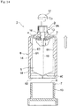
- FIG. 14 is a sectional view for illustrating a state in which the accommodation member accommodating the inner container is closed by the lid member in the refillable container illustrated in FIG. 11 .
- FIG. 11 is an exploded sectional view of the refillable container of the second example.
- FIG. 12 is a plan view for illustrating the inner container in the refillable container illustrated in FIG. 11 .
- FIG. 13 is a sectional view for illustrating a process of closing the accommodation member accommodating the inner container by the lid member in the refillable container illustrated in FIG
- FIG. 15 is a sectional view for illustrating a state in which the lid member is removed from the container accommodating the inner container in the refillable container illustrated in FIG. 11 .
- FIG. 16 is a sectional view for illustrating a state in which the lid member has been removed from the accommodation member accommodating the inner container.
- the refillable container 1 of the second example is not different from the refillable container 1 of the first example in a basic configuration, and the same configurations as those of the first example are denoted with the same reference symbols for description.
- This example is different from the first example in a shape of the inner container 5.
- the sectional shape of the body 19 is approximately circular.
- the accommodation member 7 of the second example is, similarly to the first example, the accommodation container 10 having the accommodation opening 6 which is open at the upper portion, but the sectional shape of the body is formed in a cylindrical shape to correspond to the outer shape of the inner container 5. Further, the shape of the lid member 8 is also a cylindrical shape in which the cylindrical wall portion 14 is fitted to the outer periphery of the accommodation member 7. Other configurations are the same as those in the first example.
- the inner container 5 of the second example has the body in a cylindrical shape in cross section and has a shape to be accommodated in the accommodation container 10 serving as the accommodation member 7 with almost no space.
- the inner container 5 is formed of a paper material having a thermoplastic resin layer at least on the inner surface, and has the body 19 formed in a cylindrical shape by both side edges of the rectangular paper material joined with each other.
- the protruding step portions 20 serving as the inner-container restraint part 59 are provided on the outer peripheral surface of the body 19 of the inner container 5.
- the protruding step portions 20 provided on the upper outer peripheral surface of the body 19 are arranged at positions exposed from the cutout portions 12 formed in the accommodation container 10 in a state in which the inner container 5 is accommodated in the accommodation container 10.
- the protruding height of the protruding step portions 20 is, similarly to the first example, preferably a height with which the protruding step portions 20 do not protrude outside the accommodation container 10 when the inner container 5 is accommodated in the accommodation container 10.
- the protruding step portions 20 provided on the outer peripheral surface of the body 19 of the inner container 5 are formed of the paper material by a pressing die.
- a top plate 53 is provided to serve as the upper surface 2.
- the top plate 53 has a hole 54 which is located at the center and serves as the suction port 4, and, on a back surface of the top plate 53, the sealing sheet 3 is provided so as to close the hole 54 and can be broken by penetrating the suction tube 18 of the discharge pump 9A.
- a bottom plate 55 is provided at a lower opening portion of the body 19.
- Refilling of the liquid content contained in the refillable container 1 thus configured is performed in the same manner as that in the first example.
- the inner container 5 is accommodated in the accommodation container 10.
- the protruding step portions 20 provided on the outer peripheral surface of the body 19 of the inner container 5 accommodated in the accommodation container 10 are in a state to be exposed from the cutout portions 12 formed in the accommodation container 10 (see FIG. 13 ).
- the cylindrical wall portion 14 of the lid member 8 is fitted to the outer periphery of the accommodation container 10 accommodating the inner container 5 to close the accommodation opening 6 of the accommodation container 10.
- the protruding portions 15 provided on the inner surface of the cylindrical wall portion 14 of the lid member 8 fitted to the outer periphery of the accommodation container 10 come into contact with the protruding step portions 20 exposed in the cutout portions 12 which are formed in the accommodation container 10, and similarly to the first example, the protruding step portions 20 are elastically deformed, and the protruding portions 15 ride over the protruding step portions 20 to move in the cutout portions 12.
- the protruding portions 15 provided on the inner surface of the cylindrical wall portion 14 of the lid member 8 engage with lower sides of the protruding step portions 20 of the inner container 5 (see FIG. 15 ), and the inner container 5 is taken out from inside the accommodation container 10 integrally with the lid member 8 (see FIG. 16 ).
- the protruding step portions 20 ride over the protruding portions 15 so that the inner container 5 can be taken out from the lid member 8.
- the accommodation opening 6 through which the inner container 5 is accommodated in the accommodation member 7 is open at the upper portion, but is not limited to this, and may be open at a side.
- the taking-out part 9 is mounted to the lid member 8 to be integrated with the lid member 8, but is not always required to be mounted to the lid member 8.
- FIG. 17 to FIG. 21 are views for illustrating a third example of the refillable container according to the embodiment of the present invention.
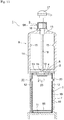
- FIG. 17 is an exploded sectional view of the refillable container of the third example.
- FIG. 18 is a partially cutaway perspective view for illustrating the accommodation member and the lid member in the refillable container illustrated in FIG. 17 .
- FIG. 19 is a sectional view for illustrating a process of closing the accommodation container accommodating the inner container by the lid member in the refillable container illustrated in FIG. 17 .
- FIG. 20 is a sectional view for illustrating a state in which the accommodation member accommodating the inner container is closed by the lid member.
- FIG. 21 is a sectional view for illustrating a state in which the lid member is removed from the accommodation member accommodating the inner container in the refillable container illustrated in FIG. 17 .
- the refillable container 1 of the third example is not different from the refillable container 1 of the first example in a basic configuration, and the same configurations as those of the first example are denoted with the same reference symbols for description.
- This example is different from the first example in the accommodation member 7 configured to accommodate the inner container 5, and other configurations are the same as those of the first example.
- the accommodation member 7 of this example includes a support base portion 56 and a support frame portion 58 in which a plurality of support pieces 57 along the outer surface of the body 19 of the inner container 5 are vertically provided at intervals on an upper surface of the support base portion 56, and the inner container 5 is accommodated inside the support frame portion 58.
- the inner container 5 of this example has the same configuration as the inner container 5 of the first example.
- the support pieces 57 vertically provided on the upper surface of the support base 56 four support pieces 57 are vertically provided so as to correspond to corner portions of the inner container 5 having the body 19 approximately in a rectangular shape in cross section.
- Each support piece 57 has an angle inner surface which supports both side surfaces of the corner portion of the inner container 5.
- the height of the support pieces 57 vertically provided on the upper surface of the support base portion 56 is not particularly limited as long as the support pieces 57 have a height by which the inner container 5 inserted into the support frame portion 58 can be stably supported.
- the protruding portions 15 provided on the inner surface of the cylindrical wall portion 14 of the lid member 8 are, in this example, provided linearly in an axial direction of the cylindrical wall portion 14, and the protruding portions 15 are provided so as to be positioned between the support pieces 57 of the support frame portion 58 serving as the accommodation member 7 when the accommodation member 7 is closed by the lid member 8.
- the protruding step portions 20 provided on the outer peripheral surface of the body 19 in the inner container 5 are provided so as to be positioned above the accommodation opening 6 of the support frame portion 58, but the protruding step portions 20 are provided to be positioned between the support pieces 57 when the protruding step portions 20 provided on the outer peripheral surface of the body 19 of the inner container 5 are provided to be positioned below the accommodation opening 6 of the support frame portion 58.
- Refilling of the liquid content contained in the refillable container 1 thus configured is performed in the same manner as that in the first example.
- the inner container 5 is accommodated in the support frame portion 58 serving as the accommodation member 7.
- the protruding step portions 20 provided on the outer peripheral surface of the body 19 of the inner container 5 accommodated in the support frame portion 58 are exposed above the accommodation opening 6 of the support frame portion 58 (see FIG. 19 ). Further, when the protruding step portions 20 provided on the outer peripheral surface of the body 19 in the inner container 5 are provided so as to be positioned below the accommodation opening 6 of the support frame portion 58, the protruding step portions 20 are exposed between the support pieces 57 (not shown).
- the cylindrical wall portion 14 of the lid member 8 is fitted to the outer periphery of the support frame portion 58 accommodating the inner container 5 to close the accommodation opening 6 of the support frame portion 58.
- the linear protruding portions 15 provided on the inner surface of the cylindrical wall portion 14 of the lid member 8 come into contact with the protruding step portions 20 exposed from the support frame portion 58.
- the protruding step portions 20 are elastically deformed and protruding portions 15 ride over the protruding step portions 20 to move, and further, end portions at an advancing side of the linear protruding portions 15 move between the support pieces 57 of the support frame portion 58.
- the suction tube 18 arranged on the lower surface side of the top plate portion 13 of the lid member 8 tears the sealing sheet 3 arranged at the upper surface 2 of the inner container 5 accommodated in the support frame portion 58 to be inserted from the suction port 4 into the inner container 5.
- the protruding step portions 20 ride over the protruding portions 15 so that the inner container 5 can be taken out from the lid member 8.
- the accommodation opening 6 through which the inner container 5 is accommodated in the accommodation member 7 is open at the upper portion, but is not limited to this, and may be open at a side.
- the taking-out part 9 is mounted to the lid member 8 to be integrated with the lid member 8, but is not always required to be mounted to the lid member 8.
- FIG. 22 to FIG. 29 are views for illustrating a fourth example of the refillable container according to the embodiment of the present invention.
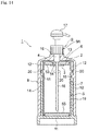
- FIG. 22 is an exploded sectional view of the refillable container of the fourth example.
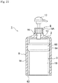
- FIG. 23 is a sectional view for illustrating a state in which the accommodation member accommodating the inner container is closed by the lid member in the refillable container illustrated in FIG. 22 .
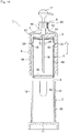
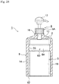
- FIG. 24 is a sectional view for illustrating a state in which the lid member is removed from the accommodation member accommodating the inner container in the refillable container illustrated in FIG. 22 .
- FIG. 25 is a sectional view for illustrating a state in which the inner container accommodated in the lid member which has been removed from the accommodation member is taken out from the lid member in the refillable container illustrated in FIG. 22 .
- FIG. 22 is an exploded sectional view of the refillable container of the fourth example.
- FIG. 23 is a sectional view for illustrating a state in which the accommodation member accommodating the inner container is closed by the lid member in the refillable container
- FIG. 26 is a schematic transverse sectional view for illustrating another example of a contact portion provided in the lid member in the refillable container of the fourth example.
- FIG. 27 is a sectional view for illustrating one example of the contact portion provided in the inner container in the refillable container of the fourth example.
- FIG. 28 is a sectional view for illustrating one example of the contact portion provided in the lid member and the inner container in the refillable container of the fourth example.
- FIG. 29 is a perspective view for illustrating another example of the accommodation member in the refillable container of the fourth example.
- the refillable container 1 of the fourth example is not different from the refillable container 1 of the first example in a basic configuration, and the same configurations as those of the first example are denoted with the same reference symbols for description.
- the fourth example is different from the first example in the inner-container restraint part 59 to restrain the lid member 8 and the inner container 5, and other configurations are the same as those in the first example.
- the inner-container restraint part 59 is provided on one or both of the inner surface of the cylindrical wall portion 14 of the lid member 8 and the outer surface of the body 19 of the inner container 5, and is formed of a contact portion 60 configured to make the inner wall of the cylindrical wall portion 14 come into contact with the outer surface of the body 19 of the inner container 5.
- the lid member 8 and the inner container 5 are restrained by a resistance force of the contact portion 60.
- a length of the accommodation container 10 is set to a length with which the inner container 5 at least protrudes from the accommodation opening 6 of the accommodation container 10, and the outer surface of the body 19 of the inner container 5 faces the inner surface of the lid member 8 which closes the accommodation member 7 outside the accommodation container 10.
- the contact portion 60 serving as the inner-container restraint part 59 is provided on the inner surface of the cylindrical wall portion 14 of the lid member 8.
- the contact portion 60 provided on the inner surface of the cylindrical wall portion 14 of the lid member 8 is, in the fourth example, formed by a plurality of ribs 61 extending in a longitudinal direction.
- the height of the ribs 61 is set to a height at which the ribs 61 come into contact with the outer surface of the body 19 of the inner container 5 with a predetermined pressing force.
- the resistance force of the contact portion 60 provided on the inner surface of the cylindrical wall portion 14 of the lid member 8 which comes into contact with the outer surface of the body 19 of the inner container 5 is as follows.
- the resistance force of the contact portion 60 at the time of pulling out the inner container 5 accommodated in the lid member 8 from the opening portion 62 of the lid member 8 is represented by X1
- a lower limit resistance force to prevent the inner container 5 from falling from the opening portion of the lid member by its own weight is represented by X2
- an upper limit resistance force capable of pulling out the inner container 5 accommodated in the lid member 8 from the opening portion 62 of the lid member 8 in a state in which the content contained in the inner container 5 accommodated in the lid member 8 has been exhausted is represented by X3.
- the resistance force X1 given at the time of pulling out the inner container 5 accommodated in the lid member 8 from the opening portion 62 of the lid member 8 is set within a range defined by X2 ⁇ X1 ⁇ X3.
- the lower limit resistance force X2 may be calculated with the inner container 5 in a state in which the content has been exhausted, or with the inner container 5 in a state in which the content is fully contained.
- the upper limit resistance force X3 is preferably calculated as a resistance force capable of pulling out the inner container 5 from the opening portion 62 of the lid member 8 without difficulty in a state in which the content contained in the inner container 5 accommodated in the lid member 8 has been exhausted.
- the resistance force capable of pulling out without difficulty refers to a resistance force which allows an adult to hold and easily pull out the inner container 5 accommodated in the lid member 8 without particularly being conscious of a strong force.
- the upper limit resistance force X3 was calculated as follows.
- the resistance force at the time of pulling out the inner container 5 from the opening portion 62 of the lid member 8 was changed, and resistance feeling at the time of pulling out was evaluated by sensory. Further, the resistance force at that time was measured using a push-pull gauge.
- the resistance force X1, the lower limit resistance force X2, and the upper limit resistance force X3 are controlled by controlling mutual pressing forces of the cylindrical wall portion 14 of the lid member 8 and of the body 19 of the inner container 5 at the contact portion 60, and a friction coefficient at the contact portion 60.
- the contact portion 60 is formed by the ribs 61, but is not limited thereto.
- protrusions (not shown) formed by embossing may be formed on the inner surface of the cylindrical wall portion 14 of the lid member 8 to form the contact portion 60, or as illustrated in FIG. 26 , portions of the cylindrical wall portion 14 of the lid member 8 may be concavely bent to form recessed curve portions 63, and the recessed curve portions 63 may be used as the contact portion 60.
- the pressing force at the contact portion 60 is controlled by the height, shape, contact area, or the like of the ribs 61, the embossed portions, or the recessed curve portions 63 or the like.
- the friction coefficient at the contact portion 60 is controlled by processing a surface of the inner surface of the cylindrical wall portion 14 of the lid member 8 (for example, mat, mirror, etc.), applying an anti-slip agent or the like, or providing a rubber layer, a silicon layer, or the like.
- the operation of refilling the liquid content is performed as described below.
- the operation of refilling the liquid content contained in the refillable container 1 includes an accommodation operation and a taking-out operation.
- the accommodation operation the inner container 5 is accommodated in the accommodation container 10 serving as the accommodation member 7 in the refillable container 1.
- the taking-out operation the inner container 5 accommodated in the accommodation container 10 is taken out from the accommodation container 10.
- the inner container 5 In the accommodation operation of the inner container 5 in the accommodation container 10, first, the inner container 5 is accommodated in the accommodation container 10.
- the cylindrical wall portion 14 of the lid member 8 is fitted to the outer periphery of the accommodation container 10 accommodating the inner container 5 to close the accommodation opening 6 of the accommodation container 10.
- the ribs 61 serving as the contact portion 60 provided on the inner surface of the cylindrical wall portion 14 of the lid member 8 move in a closing direction while coming into contact with the outer surface of the body 19 of the inner container 5.
- the suction tube 18 arranged on the lower surface side of the top plate portion 13 of the lid member 8 tears the sealing sheet 3 arranged on the upper surface 2 of the inner container 5 accommodated in the accommodation container 10 to be inserted from the suction port 4 into the inner container 5.
- the accommodation opening 6 of the accommodation container 10 is closed by the lid member 8, and the accommodation operation of the inner container 5 into the accommodation container 10 is completed.
- the outer surface of the body 19 of the inner container 5 accommodated in the accommodation container 10 is in contact with the ribs 61 serving as the contact portion 60 which is provided on the inner surface of the cylindrical wall portion 14 of the lid member 8 (see FIG. 23 ).
- the resistance force of the contact portion 60 provided on the inner surface of the cylindrical wall portion 14 of the lid member 8 which comes into contact with the outer surface of the body 19 of the inner container 5 is such that: in the case in which the resistance force of the contact portion 60 at the time of pulling out the inner container 5 accommodated in the lid member 8 from the opening portion 62 of the lid member 8 is represented by X1, the lower limit resistance force to prevent the inner content 5 from falling from the opening portion of the lid member by its own weight is represented by X2, and the upper limit resistance force capable of pulling out the inner container 5 accommodated in the lid member 8 from the opening portion 8 of the lid member 8 in a state in which the content has been exhausted is represented by X3, the resistance force X1 given at the time of pulling out the inner container 5 accommodated in the lid member 8 from the opening portion 62 of the lid member 8 is set within the range of X2 ⁇ X1 ⁇ X3.
- the lid member 8 when the lid member 8 is removed from the accommodation container 10 accommodating the inner container 5, the inner container 5 accommodated in the lid member 8 is taken out from the accommodation container 10 integrally with the lid member 8, and the inner container 5 is prevented from falling from the lid member 8 even when the opening portion 62 of the lid member 8 is oriented downward (see FIG. 24 ).
- taking out the inner container 5 from the lid member 8 can be performed, with the condition of X1 ⁇ X3, by holding the inner container 5 exposed from the opening portion 62 of the lid member 8 to pull out reliably from the opening portion 62 of the lid member 8 (see FIG. 25 ).
- the lower limit resistance force X2 is calculated with the inner container 5 in a state in which the content is fully contained
- the inner container 5 accommodated in the lid member 8 can be reliably taken out from the accommodation container 10 integrally with the lid member 8.
- the upper limit resistance force X3 is calculated as a resistance force capable of pulling out the inner container 5 from the opening portion 62 of the lid member 8 without difficulty in a state in which the content contained in the inner container 5 accommodated in the lid member 8 has been exhausted, the inner container 5 in which the content has been exhausted can be easily and reliably pulled out from the opening portion 62 of the lid member 8.
- the contact portion 60 at which the inner surface of the cylindrical wall portion 14 of the lid member 8 comes in contact with the outer surface of the inner container 5 accommodated in the lid member 8 is formed with the contact portion 60 on the inner surface of the cylindrical wall portion 14 of the lid member 8.
- the contact portion 60 may be formed by forming an annular protruding portion 64 around the outer surface of the body 19 of the inner container 5, or, as illustrated in FIG.
- the contact portion 60 may be formed by forming the annular protruding portion 64 around the outer surface of the body 19 of the inner container 5, and forming an annular protruding portion 65 which comes into contact with the annular protruding portion 64 around the inner surface of the cylindrical wall portion 14 of the lid member 8.
- the contact portion 60 at which the inner surface of the cylindrical wall portion 14 of the lid member 8 comes into contact with the outer surface of the inner container 5 accommodated in the lid member 8 is not always required to be formed by the protrusions such as the ribs 61 formed on the inner surface of the cylindrical wall portion 14 of the lid member 8, the annular protruding portion 64 formed around the outer surface of the body 19 of the inner container 5, and the annular protruding portion 64 formed around the outer surface of the body 19 of the inner container 5 and the annular protruding portion 65 formed around the inner surface of the cylindrical wall portion 14 of the lid member 8.
- the inner surface of the cylindrical wall portion 14 of the lid member 8 comes into contact with the outer surface of the container 5 to form the contact portion 60, and the resistance force of the resistance force X1, the lower limit resistance force X2, and the upper limit resistance force X3 may be controlled by controlling the friction coefficient only by the materials of the cylindrical wall portion 14 of the lid member 8 and the inner container 5.
- the accommodation member 7 is a cylindrical accommodation container 10 having the accommodation opening 6 at the upper portion, but is not limited thereto.
- the accommodation member 7 may be formed by, as the accommodation member 7 of the third example, the support base portion 56 and the support frame portion 58 which is formed vertically by a plurality of support pieces 57 at intervals along the outer surface of the body 19 of the inner container 5 on the upper surface of the support base portion 56 to configure in a pedestal shape in which the inner container 5 is accommodated inside the support frame portion 58.
- the accommodation opening 6 through which the inner container 5 is accommodated in the accommodation member 7 is open at the upper portion, but is not limited to this, and may be open at a side.
- the inner container 5 is formed of a paper material, but is not limited thereto, and may be formed of a resin material.
- the shape of the body 19 is not limited to a rectangular cylindrical shape and may be formed in a cylindrical shape.
- the taking-out part 9 is mounted to the lid member 8 to be integrated with the lid member 8, but is not always required to be mounted to the lid member 8.
Landscapes
- Engineering & Computer Science (AREA)
- Mechanical Engineering (AREA)
- Packages (AREA)
- Containers And Packaging Bodies Having A Special Means To Remove Contents (AREA)
Abstract
Description
- The present invention relates to a refillable container which can be refilled with a liquid content such as cosmetics and detergents.
- As a refillable container which can be refilled with a liquid content such as cosmetics and detergents, there has hitherto been known a refillable container including: an inner container configured to contain a content and be replaced when the content has been exhausted; an accommodation member, which has an accommodation opening, and is configured to accommodate the inner container; a cylindrical lid member fitted to the accommodation member accommodating the inner container to close the accommodation member; and a taking-out part configured to take out the content contained in the inner container accommodated in the accommodation member (see, for example,
Patent Literatures 1 and 2). - Refilling is performed with the refillable containers described in
Patent Literatures - In general, in many cases, an inner container configured to contain a content is formed into a shape having a size which is suitable to be accommodated in an accommodation member in a state in which a gap with the accommodation member is small so as to prevent the accommodation member from becoming larger more than necessary. Therefore, it is troublesome to perform an operation of taking out the inner container in which a liquid content has been exhausted from the accommodation member.
- According to the refillable container described in
Patent Literature 1, a container main body serving as an inner container has a neck portion, and the neck portion has a mouth portion. Thus, the inner container can be easily taken out from the accommodation member by holding the neck portion. Further, according to the refillable container described inPatent Literature 2, a mouth plug is mounted so as to protrude on a flat upper surface of an inner container. Thus, the inner container can be easily taken out from an accommodation member by holding the mouth plug. -
- [PTL 1]
JP 2003-252338 A - [PTL 2]
JP 05-81051 A - The inner container can be easily taken out from the accommodation member by holding the neck portion formed in the inner container with the refillable container described in
Patent Literature 1, or by holding and pulling up the mouth plug mounted to the flat upper surface of the inner container with the refillable container as described inPatent Literature 2. However, the neck portion formed in the inner container or the mouth plug mounted to the flat upper surface of the inner container creates a needless space in the accommodation member configured to accommodate the inner container. Therefore, there arises a problem in that the accommodation member becomes larger more than necessary. - Further, there arises a problem in that the neck portion formed in the inner container or the mouth plug mounted to the flat upper surface of the inner container causes an increase in manufacturing cost of the inner container.
- An object of the present invention is to provide a refillable container which allows an inner container to be easily taken out from an accommodation member so as to enable an operation of refilling a content through replacement of the inner container to be easily performed, and which enables reduction in size of the accommodation member configured to accommodate the inner container.
- In order to achieve the above-mentioned objects, according to the invention described in
claim 1, there is provided a refillable container including: an inner container configured to contain a content and be replaced when the content has been exhausted; an accommodation member, which has an accommodation opening, and is configured to accommodate the inner container; a cylindrical lid member, which is to be fitted to the accommodation member accommodating the inner container, and is configured to close the accommodation member; a taking-out part configured to take out the content contained in the inner container accommodated in the accommodation member; and an inner-container restraint part, which is provided between the lid member and the inner container, is configured to restrain the lid member and the inner container so as to prevent the inner container from falling from an opening portion of the lid member by its own weight when the lid member is removed from the accommodation member, and is configured to release the restraint between the lid member and the inner container when the inner container in which the content has been exhausted is pulled from the opening portion of the lid member in a pull-out direction. - According to the invention described in
claim 1, when the lid member is removed from the accommodation member accommodating the inner container, the inner container accommodated in the lid member is taken out from the accommodation member integrally with the lid member through intermediation of the inner-container restraint part. Accordingly, even when the opening portion of the lid member is oriented downward, the inner container is prevented from falling from the lid member. Then, the inner container in which the content has been exhausted can be reliably pulled out from the opening portion of the lid member. - According to the invention described in
claim 2, in the invention described inclaim 1, the inner-container restraint part includes: a protruding step portion provided on an upper outer surface of a body of the inner container; and a protruding portion provided on an inner surface of a cylindrical wall portion which is fitted to an outer periphery of the accommodation member of the lid member. At a time of an operation of closing the accommodation member by the lid member, the protruding portion rides over the protruding step portion provided on the upper outer surface of the inner container accommodated in the accommodation member. At a time of an operation of removing the lid member from the accommodation member, the protruding portion engages with a lower side of the protruding step portion so as to restrain the inner container and prevent the inner container from falling from the opening portion of the lid member by its own weight, and the restraint is released by pulling the inner container from the opening portion of the lid member so that the protruding step portion rides over the protruding portion. - According to the invention described in
claim 2, at the time of the operation of removing the lid member from the accommodation member, the protruding portion provided on the inner surface of the cylindrical wall portion of the lid member engages with the lower side of the protruding step portion provided on the inner container accommodated in the accommodation member, and the inner container is taken out from inside the accommodation member integrally with the lid member, and the inner container is prevented from falling from the lid member even when the opening portion of the lid member is oriented downward. - Then, when the inner container in which the content has been exhausted is pulled from the opening portion of the lid member, the protruding step portion rides over the protruding portion, and hence the inner container can be reliably pulled out from the opening portion of the lid member.
- According to the invention described in
claim 3, in the invention described inclaim 2, the protruding step portion provided on the upper outer surface of the body of the inner container is provided at an upper end edge portion of the body. - According to the invention described in
claim 3, at the time of the operation of removing the lid member from the accommodation member, the protruding portion provided on the inner surface of the cylindrical wall portion of the lid member engages with the lower side of the protruding step portion provided on the upper end edge of the body of the inner container accommodated in the accommodation member so that the inner container is taken out from the accommodation member integrally with the lid member. - According to the invention described in
claim 4, in the invention described inclaim 2, the protruding step portion provided on the upper outer surface of the body of the inner container is provided on an outer peripheral surface of the body. - According to the invention described in
claim 4, at the time of the operation of removing the lid member from the accommodation member, the protruding portion provided on the inner surface of the cylindrical wall portion of the lid member engages with the lower side of the protruding step portion provided on the outer peripheral surface of the body of the inner container accommodated in the accommodation member so that the inner container is taken out from the accommodation member integrally with the lid member. - According to the invention described in
claim 5, in the invention described inclaim 1, the inner-container restraint part is provided on one or both of an inner surface of a cylindrical wall portion of the lid member and an outer surface of a body of the inner container, and is formed of a contact portion configured to make the inner surface of the cylindrical wall portion of the lid member come into contact with the outer surface of the body of the inner container. In a case in which a resistance force of the contact portion at a time of pulling out the inner container from an opening portion of the lid member is represented by X1, a lower limit resistance force to prevent the inner content from falling from the opening portion of the lid member by its own weight is represented by X2, and an upper limit resistance force capable of pulling out the inner container accommodated in the lid member from the opening portion of the lid member in a state in which the content has been exhausted is represented by X3, the resistance force X1 given at the time of pulling out the inner container accommodated in the lid member from the opening portion of the lid member is set within a range defined by X2≤X1≤X3. - According to the invention described in
claim 5, X2≤X1≤X3 is set, and hence, when the lid member is removed from the accommodation member accommodating the inner container, the inner container accommodated in the lid member is taken out from the accommodation member integrally with the lid member, and even when the opening portion of the lid member is oriented downward, the inner container is prevented from falling from the lid member. Then, the inner container in which the content has been exhausted can be pulled out reliably from the opening portion of the lid member. - According to the invention described in
claim 6, in the invention described inclaim 5, the lower limit resistance force X2 is calculated with the inner container in a state in which the content has been exhausted. - According to the present invention described in
claim 6, the lower limit resistance force X2 is calculated with the inner container in a state in which the content has been exhausted, and hence, when the lid is removed from the accommodation member after the content has been exhausted, the inner container is prevented from falling from inside the lid member by its own weight, and the inner container accommodated in the lid member is reliably taken out from the accommodation member integrally with the lid member. - According to the invention described in
claim 7, in the invention described inclaim 5, the lower limit resistance force X2 is calculated with the inner container in a state in which the content is fully contained. - According to the invention described in
claim 7, the lower limit resistance force X2 is calculated with the inner container in a state in which the content is fully contained, and hence, when the lid member is removed from the accommodation member in the state in which the content is fully contained in the inner container, the inner container is prevented from falling from inside the lid member by its own weight, and the inner container accommodated in the lid member can be taken out reliably from the accommodation member integrally with the lid member. - According to the invention as described in
claim 8, in the invention described in any one ofclaims 5 to 7, the upper limit resistance force X3 is calculated as a resistance force capable of pulling out the inner container from the opening portion of the lid member without difficulty in a state in which the content contained in the inner container accommodated in the lid member has been exhausted. - According to the invention described in
claim 8, the upper limit resistance force X3 is calculated as a resistance force capable of pulling out the inner container from the opening portion of the lid member without difficulty in the state in which the content contained in the inner container accommodated in the lid member has been exhausted, and hence the inner container in which the content has been exhausted can be easily and reliably pulled out from the opening portion of the lid member. - According to the refillable container of the present invention, when the lid member is removed from the accommodation member in the operation of refilling in which an inner container is replaced by a new inner container, the inner container accommodated in the accommodation member can be taken out from the accommodation member integrally with the lid member, and the inner container in which a content has been exhausted can be pulled out from an opening of the lid member. Accordingly, the operation of refilling the content through replacement of the inner container can be easily performed.
- Further, the inner container is not required to have a protruding portion such as a mouth plug also serving as a holding portion at the time of taking out from the accommodation member on the upper surface, and thereby a needless space in the accommodation member accommodating the inner container is eliminated and the accommodation member can be reduced in size by the amount corresponding to the needless space.
-
-
FIG. 1 is an exploded sectional view for illustrating a first example of a refillable container according to an embodiment of the present invention. -
FIG. 2 is a perspective view for illustrating an inner container of the refillable container illustrated inFIG. 1 . -
FIG. 3 is a sectional view taken along the line A-A ofFIG. 2 . -
FIG. 4 is a developed view for illustrating a carton blank before an assembly process of the inner container illustrated inFIG. 2 . -
FIG. 5 is an explanatory view for illustrating a step of forming an upper surface of the inner container illustrated inFIG. 2 . -
FIG. 6 is an explanatory view for illustrating a step of forming the upper surface of the inner container illustrated inFIG. 2 . -
FIG. 7 is a sectional view for illustrating a process of closing an accommodation member accommodating the inner container by a lid member in the refillable container illustrated inFIG. 1 . -
FIG. 8 is a sectional view for illustrating a state in which the accommodation member accommodating the inner container is closed by the lid member in the refillable container illustrated inFIG. 1 . -
FIG. 9 is a sectional view for illustrating a state in which the lid member is removed from the accommodation member accommodating the inner container in the refillable container illustrated inFIG. 1 . -
FIG. 10 is a sectional view for illustrating a state in which the lid member has been removed from the accommodation member accommodating the inner container in the refillable container illustrated inFIG. 1 . -
FIG. 11 is an exploded sectional view for illustrating a second example of the refillable container according to the embodiment of the present invention. -
FIG. 12 is a plan view for illustrating the inner container in the refillable container illustrated inFIG. 11 . -
FIG. 13 is a sectional view for illustrating a process of closing the accommodation member accommodating the inner container by a lid member in the refillable container illustrated inFIG. 11 . -
FIG. 14 is a sectional view for illustrating a state in which the accommodation member accommodating the inner container is closed by the lid member in the refillable container illustrated inFIG. 11 . -
FIG. 15 is a sectional view for illustrating a state in which the lid member is removed from the accommodation member accommodating the inner container in the refillable container illustrated inFIG. 11 . -
FIG. 16 is a sectional view for illustrating a state in which the lid member has been removed from the accommodation member accommodating the inner container in the refillable container illustrated inFIG. 11 . -
FIG. 17 is an exploded sectional view for illustrating a third example of the refillable container according to the embodiment of the present invention. -
FIG. 18 is a partially cutaway perspective view for illustrating the accommodation member and a lid member in the refillable container illustrated inFIG. 17 . -
FIG. 19 is a sectional view for illustrating a process of closing the accommodation member accommodating the inner container by a lid member in the refillable container illustrated inFIG. 17 . -
FIG. 20 is a sectional view for illustrating a state in which the accommodation member accommodating the inner container is closed by the lid member in the refillable container illustrated inFIG. 17 . -
FIG. 21 is a sectional view for illustrating a state in which the lid member is removed from the accommodation member accommodating the inner container in the refillable container illustrated inFIG. 17 . -
FIG. 22 is an exploded sectional view for illustrating a fourth example of the refillable container according to the embodiment the present invention. -
FIG. 23 is a sectional view for illustrating a state in which the accommodation member accommodating the inner container is closed by a lid member in the refillable container illustrated inFIG. 22 . -
FIG. 24 is a sectional view for illustrating a state in which the lid member is removed from the accommodation member accommodating the inner container in the refillable container illustrated inFIG. 22 . -
FIG. 25 is a sectional view for illustrating a state in which the inner container accommodated in the lid member, which has been removed from the accommodation member, is taken out from the lid member in the refillable container illustrated inFIG. 22 . -
FIG. 26 is a schematic transverse sectional view for illustrating another example of a contact portion provided in the lid member in the refillable container of the fourth example. -
FIG. 27 is a sectional view for illustrating an example of a contact portion provided in the inner container in the refillable container of the fourth example. -
FIG. 28 is a sectional view for illustrating an example of the contact portion provided in the lid member and the inner container in the refillable container of the fourth example. -
FIG. 29 is a perspective view for illustrating another example of the accommodation member in the refillable container of the fourth example. - Now, examples of a refillable container according to an embodiment of the present invention is described in detail with reference to the drawings.
-
FIG. 1 to FIG. 10 are views for illustrating a first example of a refillable container according to an embodiment of the present invention.FIG. 1 is an exploded sectional view of the refillable container of this example.FIG. 2 is a perspective view for illustrating an inner container in the refillable container illustrated inFIG. 1 .FIG. 3 is a sectional view taken along a line A-A ofFIG. 2 .FIG. 4 is a developed view for illustrating a carton blank before an assembly process of the inner container illustrated inFIG. 2 .FIG. 5 is an explanatory view for illustrating a step of forming an upper surface of the inner container illustrated inFIG. 2 .FIG. 6 is an explanatory view for illustrating a step of forming the upper surface of the inner container illustrated inFIG. 2 .FIG. 7 is a sectional view for illustrating a process of closing an accommodation member accommodating the inner container by a lid member in the refillable container illustrated inFIG. 1 .FIG. 8 is a sectional view for illustrating a state in which the accommodation member accommodating the inner container is closed by the lid member in the refillable container illustrated inFIG. 1 .FIG. 9 is a sectional view for illustrating a state in which the lid member is removed from the accommodation member accommodating the inner container in the refillable container illustrated inFIG. 1 .FIG. 10 is a sectional view for illustrating a state in which the lid member has been removed from the accommodation member accommodating the inner container in the refillable container illustrated inFIG. 1 . - A
refillable container 1 of the first example includes aninner container 5, anaccommodation member 7, acylindrical lid member 8, a taking-outpart 9, and an inner-container restraint part 59. Theinner container 5 has asuction port 4, which is formed on anupper surface 2 and is sealed with atearable sealing sheet 3. Theinner container 5 is configured to contain a liquid content, and is replaced when the content has been exhausted. Theaccommodation member 7 has anaccommodation opening 6 at an upper portion, and is configured to accommodate theinner container 5. Thecylindrical lid member 8 is to be fitted to theaccommodation member 7 accommodating theinner container 5, and is configured to close theaccommodation member 7. The taking-outpart 9 is configured to take out the content contained in theinner container 5 accommodated in theaccommodation member 7. The inner-container restraint part 59 is provided between thelid member 8 and theinner container 5. The inner-container restraint part 59 is configured to restrain thelid member 8 and theinner container 5 so as to prevent theinner container 5 from falling from an opening portion of thelid member 8 by its own weight when thelid member 8 is removed from theaccommodation member 7. The inner-container restraint part 59 is configured to release the restraint between thelid member 8 and theinner container 5 when theinner container 5 in which the content has been exhausted is pulled from the openingportion 62 of thelid member 8 in a pull-out direction. - First, description is made of the
accommodation member 7. - A shape of the
accommodation member 7 is not particularly limited as long as theaccommodation member 7 can secure theinner container 5. - The
accommodation member 7 of the first example is acylindrical accommodation container 10 having theaccommodation opening 6 at an upper portion. Theaccommodation container 10 is formed to have a shape corresponding to an outer shape of theinner container 5, and a cross-sectional shape of a body is a substantially square cylindrical shape in the first example. - A length of the
accommodation container 10 is such that, when theinner container 5 is accommodated in theaccommodation container 10, an end surface of theaccommodation opening 6 of theaccommodation container 10 is flush with anupper surface 2 of theinner container 5 or slightly exceeds theupper surface 2 of theinner container 5. In the first example, theaccommodation container 10 is formed to have a length slightly exceeding theupper surface 2 of theinner container 5. - Further, the
accommodation container 10 is formed withcutout portions 12 extending from theaccommodation opening 6 to abottom portion 11 side so as not to disturb movement of protruding portions formed on an inner surface of a cylindrical wall portion of thelid member 8 described later. - Next, description is made of the
lid member 8. - The
lid member 8 of the first example includes atop plate portion 13 and acylindrical wall portion 14. Thetop plate portion 13 is configured to close theaccommodation opening 6 of theaccommodation container 10. Thecylindrical wall portion 14 is fitted to an outer periphery of theaccommodation container 10. - Next, description is made of the taking-out
part 9 configured to take out the content contained in theinner container 5 accommodated in theaccommodation member 7. - The taking-out
part 9 of the first example is adischarge pump 9A which includes atubular cylinder portion 16, adischarge nozzle 17, and asuction tube 18. Thedischarge nozzle 17 is provided at an upper portion of thetubular cylinder portion 16, and serves as an operation portion of a piston freely fitted to be slidable in thetubular cylinder portion 16. Thesuction tube 18 is provided at a lower portion of thetubular cylinder portion 16. - The
discharge pump 9A serving as the taking-outpart 9 thus configured is, in the first example, mounted to thelid member 8. Specifically, thetubular cylinder portion 16 penetrates thetop plate portion 13 of thelid member 8 to be secured. Thedischarge nozzle 17 is arranged on an upper surface side of thetop plate portion 13. Thesuction tube 18 is arranged on a lower surface side of thetop plate portion 13. When thecylindrical wall portion 14 of thelid member 8 is fitted to the outer periphery of theaccommodation container 10 to close theaccommodation opening 6 of theaccommodation container 10, thesuction tube 18 arranged on the lower surface side of thetop plate portion 13 of thelid member 8 tears the sealingsheet 3 arranged at theupper surface 2 of theinner container 5 accommodated in theaccommodation container 10 to be inserted from thesuction port 4 into theinner container 5. - Next, description is made of the
inner container 5. - The
inner container 5 of the first example has abody 19 having a substantially square shape in cross section, and is shaped to be accommodated in a state in which there is almost no space in theaccommodation container 10. - The
inner container 5 of the present example is made of a paper material formed with a resin layer on at least one side thereof, has fourbody panels longitudinal folding lines body 19 formed into a rectangular tubular shape in which an edge portion of thebody panel 24 is joined by alongitudinal seal panel 29 which is connected consecutively to thebody panel 27 via a seallongitudinal folding line 28. - The
upper surface 2 of theinner container 1 is configured as described below. - A pair of upper-
surface forming panels body panels horizontal folding lines panel 34 for sealing an inner surface of the upper-surface forming panel 32 is continuously provided on an upper edge of the upper-surface forming panel 32, which underlies the upper-surface forming panel 33. - Further, a pair of
side panels body panels horizontal folding lines side panels surface forming panels surface forming panels - Further, holes 39a and 39b are formed at centers of the upper-
surface forming panels suction port 4. Theholes hole 39a and a center of thehole 39b match with each other when the upper-surface forming panels sheet 3, which is tearable, is provided on a back surface of the upper-surface forming panel 33 so as to seal thehole 39b. Asuction tube 18 of thedischarge pump 9A forming the taking-outpart 9 is stuck into the sealingsheet 3 so as to tear thefilm 3. - The sealing
sheet 3 may be pasted on a back surface of an upper-surface forming panel 33, or may be formed integrally with a laminated product which is laminated on the paper material formed with the resin layer forming theinner container 5. Further, the sealingsheet 3 is not particularly limited to the material and the configuration described above as long as the sealingsheet 3 is impermeable and tearable. As thesealing sheet 3, a resin film, a metal foil, a sheet of paper, or a laminated body thereof is exemplified. - The
upper surface 2 of theinner container 5 is formed by the upper-surface forming panels side panels body 19 is formed, first, the upper-surface forming panel 33 is folded inwardly. Along with that, theside panels body 19 is closed by the upper-surface forming panel 33. Then, the sealingpanel 34, which is continuously provided on the upper edge of the upper-surface forming panel 33, is bonded to the inner surface of the upper-surface forming panel 32 in an area of S1 so as to seal theinner container 1. Both side edges of the upper-surface forming panel 33 are bonded to theside panels FIG. 5 ). - Next, the
side panels FIG. 5 ) so that the upper-surface forming panel 32 overlies the upper-surface forming panel 33 (seeFIG. 6 ). Theside panels body 19, are folded downwardly (in directions indicated by the arrows inFIG. 6 ), and fixed to thebody 11 with an adhesive or the like. Accordingly, theupper surface 2 is formed. - In the first example, the
side panels body 19 form protrudingstep portions 20 described later as the inner-container restraint part 59. - Further, in this example, the
bottom surface 40 of theinner container 5 is configured as described below. - A pair of gable roof-shaped bottom
surface forming panels body panels horizontal folding lines Outer sealing panels surface forming panels - Further, a pair of gable wall-shaped bottom
surface forming panels body panels horizontal folding lines Inner sealing panels outer sealing panels surface forming panels - Further, the
bottom surface 40 is formed by the gable roof-shaped bottomsurface forming panels surface forming panels surface forming panels surface forming panels outer sealing panels inner container 1. Further, facing surfaces of theouter sealing panels inner sealing panels inner sealing panels inner container 1. Accordingly, thebottom surface 40 is formed into a reversed quadrangular pyramid shape of a so-called reversed gable top shape (seeFIG. 2 andFIG. 3 ). - Next, description is made of the inner-container restraint part 59 configured to restrain the
lid member 8 and theinner container 5. - In the first example, the inner-container restraint part 59 includes the protruding
step portions 20 provided on an upper outer surface of thebody 19 of theinner container 5 and protrudingportions 15 provided on an inner surface of thecylindrical wall portion 14 of thelid member 8. - The protruding
portions 15 provided on the inner surface of thecylindrical wall portion 14 of thelid member 8 are configured as follows. At the time of an operation of closing theaccommodation container 10 by thelid member 8, the protrudingportions 15 ride over the protrudingstep portions 20 provided on the upper outer periphery of theinner container 5 accommodated in theaccommodation container 10. At the time of an operation of removing thelid member 8 from theaccommodation container 10, the protrudingportions 15 engage with lower sides of the protrudingstep portions 20 so as to restrain theinner container 5 and prevent theinner container 5 from falling from the openingportion 62 of thelid member 8 by its own weight, and the protrudingstep portions 20 can ride over the protrudingportions 15 by pulling theinner container 5 from the openingportion 62 of thelid member 8. - The protruding
portions 15 thus configured are provided intermittently in a circumferential direction on the inner surface of thecylindrical wall portion 14, and are provided at positions to be entered in thecutout portions 12 formed in theaccommodation container 10 when thecylindrical wall portion 14 of thelid member 8 is fitted to the outer periphery of theaccommodation container 10. A protruding height of the protrudingportions 15 is preferably such that the protrudingportions 15 do not protrude into theaccommodation container 10 when thecylindrical wall portion 14 of thelid member 8 is fitted to the outer periphery of theaccommodation container 10. - Further, the protruding
step portion 20 provided on the upper outer surface of thebody 19 of theinner container 5 preferably has a height so as not to protrude outside theaccommodation container 10 when theinner container 5 is accommodated in theaccommodation container 10. - The protruding
step portions 20 provided on the upper outer periphery of thebody 19 of theinner container 5 are, in the first example, provided on the outer peripheral surface of thebody 19, and are provided at positions to be exposed from thecutout portions 12 formed in theaccommodation container 10 in a state in which theinner container 5 has been accommodated in theaccommodation container 10. In the first example, theside panels body 19 of theinner container 5 form protrudingstep portions 20 provided on the outer peripheral surface of thebody 19 of theinner container 5. - Refilling of the liquid content contained in the
refillable container 1 thus configured is performed as follows. - The operation of refilling the liquid content contained in the
refillable container 1 includes an accommodation operation and a taking-out operation. In the accommodation operation, theinner container 5 is accommodated in theaccommodation container 10 serving as theaccommodation member 7 in therefillable container 1. In the taking-out operation, theinner container 5 accommodated in theaccommodation container 10 is taken out from theaccommodation container 10. - In the accommodation operation of the
inner container 5 in theaccommodation container 10, first, theinner container 5 is accommodated in theaccommodation container 10. The protrudingstep portions 20 provided on the outer peripheral surface of thebody 19 of theinner container 5 accommodated in theaccommodation container 10 are in a state to be exposed from thecutout portions 12 formed in the accommodation container 10 (seeFIG. 7 ). - Next, the
cylindrical wall portion 14 of thelid member 8 is fitted to the outer periphery of theaccommodation container 10 accommodating theinner container 5 to close theaccommodation opening 6 of theaccommodation container 10. - In the process of closing the
accommodation opening 6 of theaccommodation container 10, the protrudingportions 15 provided on the inner surface of thecylindrical wall portion 14 of thelid member 8 fitted to the outer periphery of theaccommodation container 10 come into contact with the protrudingstep portions 20 exposed in thecutout portions 12 formed in theaccommodation container 10. However, when thecylindrical wall portion 14 of thelid member 8 is pushed down, the protrudingstep portions 20 of theinner container 5 is elastically deformed due to pressing of the protrudingportions 15, and the protrudingportions 15 ride over the deformed protrudingstep portions 20 to move in thecutout portions 12. - Similarly, in the process of closing the
accommodation opening 6 of theaccommodation container 10, thesuction tube 18 arranged on the lower surface side of thetop plate portion 13 of thelid member 8 tears the sealingsheet 3 arranged at theupper surface 2 of theinner container 5 accommodated in theaccommodation container 10 to be inserted from thesuction port 4 into theinner container 5. - Further, when the
cylindrical wall portion 14 of thelid member 8 fitted to the outer periphery of theaccommodation container 10 is pushed down along the outer periphery of theaccommodation container 10, theaccommodation opening 6 of theaccommodation container 10 is closed by thelid member 8, and the accommodation operation of theinner container 5 into theaccommodation container 10 is completed (seeFIG. 8 ). - When the liquid content contained in the
inner container 5 accommodated in theaccommodation container 10 has been exhausted, thelid member 8 is removed from theaccommodation container 10, and theinner container 5 in which the liquid content has been exhausted is taken out from theaccommodation container 10. - In the taking-out operation of the
inner container 5 from theaccommodation container 10, in the process of pulling up thelid member 8 to open theaccommodation opening 6 of theaccommodation container 10, the protrudingportions 15 provided on the inner surface of thecylindrical wall portion 14 of thelid member 8 engage with lower sides of the protrudingstep portions 20 of the inner container 5 (seeFIG. 9 ), and theinner container 5 is taken out from inside theaccommodation container 10 integrally with the lid member 8 (seeFIG. 10 ). - Then, through holding and pulling of the
inner container 5 exposed from the openingportion 62 of thelid member 8, the protrudingstep portions 20 ride over the protrudingportions 15 so that theinner container 5 can be taken out from thelid member 8. - In this way, the taking-out operation of the
inner container 5 accommodated in theaccommodation container 10 is completed. - In the first example, the
accommodation opening 6 through which theinner container 5 is accommodated in theaccommodation member 7 is open at the upper portion, but is not limited to this, and may be open at a side. - Further, in the first example, the taking-out
part 9 is mounted to thelid member 8 to be integrated with thelid member 8, but is not always required to be mounted to thelid member 8. -
FIG. 11 to FIG. 16 are views for illustrating a second example of the refillable container according to the embodiment of the present invention.FIG. 11 is an exploded sectional view of the refillable container of the second example.FIG. 12 is a plan view for illustrating the inner container in the refillable container illustrated inFIG. 11 .FIG. 13 is a sectional view for illustrating a process of closing the accommodation member accommodating the inner container by the lid member in the refillable container illustrated inFIG. 11 .FIG. 14 is a sectional view for illustrating a state in which the accommodation member accommodating the inner container is closed by the lid member in the refillable container illustrated inFIG. 11 .FIG. 15 is a sectional view for illustrating a state in which the lid member is removed from the container accommodating the inner container in the refillable container illustrated inFIG. 11 .FIG. 16 is a sectional view for illustrating a state in which the lid member has been removed from the accommodation member accommodating the inner container. - The
refillable container 1 of the second example is not different from therefillable container 1 of the first example in a basic configuration, and the same configurations as those of the first example are denoted with the same reference symbols for description. - This example is different from the first example in a shape of the
inner container 5. The sectional shape of thebody 19 is approximately circular. - The
accommodation member 7 of the second example is, similarly to the first example, theaccommodation container 10 having theaccommodation opening 6 which is open at the upper portion, but the sectional shape of the body is formed in a cylindrical shape to correspond to the outer shape of theinner container 5. Further, the shape of thelid member 8 is also a cylindrical shape in which thecylindrical wall portion 14 is fitted to the outer periphery of theaccommodation member 7. Other configurations are the same as those in the first example. - The
inner container 5 of the second example has the body in a cylindrical shape in cross section and has a shape to be accommodated in theaccommodation container 10 serving as theaccommodation member 7 with almost no space. - In the second example, the
inner container 5 is formed of a paper material having a thermoplastic resin layer at least on the inner surface, and has thebody 19 formed in a cylindrical shape by both side edges of the rectangular paper material joined with each other. - On the outer peripheral surface of the
body 19 of theinner container 5, the protrudingstep portions 20 serving as the inner-container restraint part 59 are provided. The protrudingstep portions 20 provided on the upper outer peripheral surface of thebody 19 are arranged at positions exposed from thecutout portions 12 formed in theaccommodation container 10 in a state in which theinner container 5 is accommodated in theaccommodation container 10. - The protruding height of the protruding
step portions 20 is, similarly to the first example, preferably a height with which the protrudingstep portions 20 do not protrude outside theaccommodation container 10 when theinner container 5 is accommodated in theaccommodation container 10. - The protruding
step portions 20 provided on the outer peripheral surface of thebody 19 of theinner container 5 are formed of the paper material by a pressing die. - At an upper opening portion of the
body 19, atop plate 53 is provided to serve as theupper surface 2. Thetop plate 53 has ahole 54 which is located at the center and serves as thesuction port 4, and, on a back surface of thetop plate 53, the sealingsheet 3 is provided so as to close thehole 54 and can be broken by penetrating thesuction tube 18 of thedischarge pump 9A. - Further, a
bottom plate 55 is provided at a lower opening portion of thebody 19. - Refilling of the liquid content contained in the
refillable container 1 thus configured is performed in the same manner as that in the first example. - In the accommodation operation of the
inner container 5 in theaccommodation container 10, first, theinner container 5 is accommodated in theaccommodation container 10. The protrudingstep portions 20 provided on the outer peripheral surface of thebody 19 of theinner container 5 accommodated in theaccommodation container 10 are in a state to be exposed from thecutout portions 12 formed in the accommodation container 10 (seeFIG. 13 ). - Next, the
cylindrical wall portion 14 of thelid member 8 is fitted to the outer periphery of theaccommodation container 10 accommodating theinner container 5 to close theaccommodation opening 6 of theaccommodation container 10. - In the process of closing the
accommodation opening 6 of theaccommodation container 10, the protrudingportions 15 provided on the inner surface of thecylindrical wall portion 14 of thelid member 8 fitted to the outer periphery of theaccommodation container 10 come into contact with the protrudingstep portions 20 exposed in thecutout portions 12 which are formed in theaccommodation container 10, and similarly to the first example, the protrudingstep portions 20 are elastically deformed, and the protrudingportions 15 ride over the protrudingstep portions 20 to move in thecutout portions 12. - Similarly, in the process of closing the
accommodation opening 6 of theaccommodation container 10, thesuction tube 18 arranged on the lower surface side of thetop plate portion 13 of thelid member 8 tears the sealingsheet 3 arranged at theupper surface 2 of theinner container 5 accommodated in theaccommodation container 10 to be inserted from thesuction port 4 into theinner container 5. - Further, when the
cylindrical wall portion 14 of thelid member 8 fitted to the outer periphery of theaccommodation container 10 is pushed down along the outer periphery of theaccommodation container 10, theaccommodation opening 6 of theaccommodation container 10 is closed by the lid member 8 (seeFIG. 14 ). - When the liquid content contained in the
inner container 5 accommodated in theaccommodation container 10 has been exhausted, thelid member 8 is removed from theaccommodation container 10, and theinner container 5 is taken out from theaccommodation container 10. - In the taking-out operation of the
inner container 5 from theaccommodation container 10, similarly to the first example, in the process of pulling up thelid member 8 to open theaccommodation opening 6 of theaccommodation container 10, the protrudingportions 15 provided on the inner surface of thecylindrical wall portion 14 of thelid member 8 engage with lower sides of the protrudingstep portions 20 of the inner container 5 (seeFIG. 15 ), and theinner container 5 is taken out from inside theaccommodation container 10 integrally with the lid member 8 (seeFIG. 16 ). - Then, through holding and pulling of the
inner container 5 exposed from the openingportion 62 of thelid member 8, the protrudingstep portions 20 ride over the protrudingportions 15 so that theinner container 5 can be taken out from thelid member 8. - In the second example, the
accommodation opening 6 through which theinner container 5 is accommodated in theaccommodation member 7 is open at the upper portion, but is not limited to this, and may be open at a side. - Further, in the second example, the taking-out
part 9 is mounted to thelid member 8 to be integrated with thelid member 8, but is not always required to be mounted to thelid member 8. -
FIG. 17 to FIG. 21 are views for illustrating a third example of the refillable container according to the embodiment of the present invention.FIG. 17 is an exploded sectional view of the refillable container of the third example.FIG. 18 is a partially cutaway perspective view for illustrating the accommodation member and the lid member in the refillable container illustrated inFIG. 17 .FIG. 19 is a sectional view for illustrating a process of closing the accommodation container accommodating the inner container by the lid member in the refillable container illustrated inFIG. 17 .FIG. 20 is a sectional view for illustrating a state in which the accommodation member accommodating the inner container is closed by the lid member.FIG. 21 is a sectional view for illustrating a state in which the lid member is removed from the accommodation member accommodating the inner container in the refillable container illustrated inFIG. 17 . - The
refillable container 1 of the third example is not different from therefillable container 1 of the first example in a basic configuration, and the same configurations as those of the first example are denoted with the same reference symbols for description. - This example is different from the first example in the
accommodation member 7 configured to accommodate theinner container 5, and other configurations are the same as those of the first example. - The
accommodation member 7 of this example includes asupport base portion 56 and asupport frame portion 58 in which a plurality ofsupport pieces 57 along the outer surface of thebody 19 of theinner container 5 are vertically provided at intervals on an upper surface of thesupport base portion 56, and theinner container 5 is accommodated inside thesupport frame portion 58. - The
inner container 5 of this example has the same configuration as theinner container 5 of the first example. As thesupport pieces 57 vertically provided on the upper surface of thesupport base 56, foursupport pieces 57 are vertically provided so as to correspond to corner portions of theinner container 5 having thebody 19 approximately in a rectangular shape in cross section. Eachsupport piece 57 has an angle inner surface which supports both side surfaces of the corner portion of theinner container 5. When theinner container 5 is inserted into thesupport frame portion 58 from theaccommodation opening 6 formed at an upper portion of thesupport frame portion 58 formed by the foursupport pieces 57, each corner portion of theinner container 5 is accommodated on the angle inner surface of eachpiece 57 with almost no clearance. - Further, the height of the
support pieces 57 vertically provided on the upper surface of thesupport base portion 56 is not particularly limited as long as thesupport pieces 57 have a height by which theinner container 5 inserted into thesupport frame portion 58 can be stably supported. - Still further, the protruding
portions 15 provided on the inner surface of thecylindrical wall portion 14 of thelid member 8 are, in this example, provided linearly in an axial direction of thecylindrical wall portion 14, and the protrudingportions 15 are provided so as to be positioned between thesupport pieces 57 of thesupport frame portion 58 serving as theaccommodation member 7 when theaccommodation member 7 is closed by thelid member 8. - Yet further, in this example, when the
inner container 5 is accommodated in thesupport frame portion 58 serving as theaccommodation member 7, the protrudingstep portions 20 provided on the outer peripheral surface of thebody 19 in theinner container 5 are provided so as to be positioned above theaccommodation opening 6 of thesupport frame portion 58, but the protrudingstep portions 20 are provided to be positioned between thesupport pieces 57 when the protrudingstep portions 20 provided on the outer peripheral surface of thebody 19 of theinner container 5 are provided to be positioned below theaccommodation opening 6 of thesupport frame portion 58. - Refilling of the liquid content contained in the
refillable container 1 thus configured is performed in the same manner as that in the first example. - In the accommodation operation of the
inner container 5 into theaccommodation member 7, first, theinner container 5 is accommodated in thesupport frame portion 58 serving as theaccommodation member 7. The protrudingstep portions 20 provided on the outer peripheral surface of thebody 19 of theinner container 5 accommodated in thesupport frame portion 58 are exposed above theaccommodation opening 6 of the support frame portion 58 (seeFIG. 19 ). Further, when the protrudingstep portions 20 provided on the outer peripheral surface of thebody 19 in theinner container 5 are provided so as to be positioned below theaccommodation opening 6 of thesupport frame portion 58, the protrudingstep portions 20 are exposed between the support pieces 57 (not shown). - Next, the
cylindrical wall portion 14 of thelid member 8 is fitted to the outer periphery of thesupport frame portion 58 accommodating theinner container 5 to close theaccommodation opening 6 of thesupport frame portion 58. - In the process of closing the
accommodation opening 6 of thesupport frame portion 58, the linear protrudingportions 15 provided on the inner surface of thecylindrical wall portion 14 of thelid member 8 come into contact with the protrudingstep portions 20 exposed from thesupport frame portion 58. Similarly to the first example, the protrudingstep portions 20 are elastically deformed and protrudingportions 15 ride over the protrudingstep portions 20 to move, and further, end portions at an advancing side of the linear protrudingportions 15 move between thesupport pieces 57 of thesupport frame portion 58. - Similarly, in the process of closing the
accommodation opening 6 of thesupport frame portion 58, thesuction tube 18 arranged on the lower surface side of thetop plate portion 13 of thelid member 8 tears the sealingsheet 3 arranged at theupper surface 2 of theinner container 5 accommodated in thesupport frame portion 58 to be inserted from thesuction port 4 into theinner container 5. - Further, when the
cylindrical wall portion 14 of thelid member 8 fitted to the outer periphery of thesupport frame portion 58 is pushed down along the outer periphery of theaccommodation container 10, theaccommodation opening 6 of thesupport frame portion 58 is closed by the lid member 8 (seeFIG. 20 ). - When the liquid content contained in the
inner container 5 accommodated in thesupport frame portion 58 has been exhausted, thelid member 8 is removed from thesupport frame portion 58, and theinner container 5 is taken out from thesupport frame portion 58. - In the taking-out operation of the
inner container 5 from thesupport frame portion 58, similarly to the first example, in the process of pulling up thelid member 8 to open theaccommodation opening 6 of thesupport frame portion 58, the protrudingportions 15 provided on the inner surface of thecylindrical wall portion 14 of thelid member 8 engage with lower sides of the protrudingstep portions 20 of theinner container 5, and theinner container 5 is taken out from inside thesupport frame portion 58 integrally with the lid member 8 (seeFIG. 21 ). - Then, through holding and pulling of the
inner container 5 exposed from the openingportion 62 of thelid member 8, the protrudingstep portions 20 ride over the protrudingportions 15 so that theinner container 5 can be taken out from thelid member 8. - In the third example, the
accommodation opening 6 through which theinner container 5 is accommodated in theaccommodation member 7 is open at the upper portion, but is not limited to this, and may be open at a side. - Further, in the third example, the taking-out
part 9 is mounted to thelid member 8 to be integrated with thelid member 8, but is not always required to be mounted to thelid member 8. -
FIG. 22 to FIG. 29 are views for illustrating a fourth example of the refillable container according to the embodiment of the present invention.FIG. 22 is an exploded sectional view of the refillable container of the fourth example.FIG. 23 is a sectional view for illustrating a state in which the accommodation member accommodating the inner container is closed by the lid member in the refillable container illustrated inFIG. 22 .FIG. 24 is a sectional view for illustrating a state in which the lid member is removed from the accommodation member accommodating the inner container in the refillable container illustrated inFIG. 22 .FIG. 25 is a sectional view for illustrating a state in which the inner container accommodated in the lid member which has been removed from the accommodation member is taken out from the lid member in the refillable container illustrated inFIG. 22 .FIG. 26 is a schematic transverse sectional view for illustrating another example of a contact portion provided in the lid member in the refillable container of the fourth example.FIG. 27 is a sectional view for illustrating one example of the contact portion provided in the inner container in the refillable container of the fourth example.FIG. 28 is a sectional view for illustrating one example of the contact portion provided in the lid member and the inner container in the refillable container of the fourth example.FIG. 29 is a perspective view for illustrating another example of the accommodation member in the refillable container of the fourth example. - The
refillable container 1 of the fourth example is not different from therefillable container 1 of the first example in a basic configuration, and the same configurations as those of the first example are denoted with the same reference symbols for description. - The fourth example is different from the first example in the inner-container restraint part 59 to restrain the
lid member 8 and theinner container 5, and other configurations are the same as those in the first example. - In the fourth example, the inner-container restraint part 59 is provided on one or both of the inner surface of the
cylindrical wall portion 14 of thelid member 8 and the outer surface of thebody 19 of theinner container 5, and is formed of acontact portion 60 configured to make the inner wall of thecylindrical wall portion 14 come into contact with the outer surface of thebody 19 of theinner container 5. Thelid member 8 and theinner container 5 are restrained by a resistance force of thecontact portion 60. - Accordingly, when the
inner container 5 is accommodated in theaccommodation container 10, a length of theaccommodation container 10 is set to a length with which theinner container 5 at least protrudes from theaccommodation opening 6 of theaccommodation container 10, and the outer surface of thebody 19 of theinner container 5 faces the inner surface of thelid member 8 which closes theaccommodation member 7 outside theaccommodation container 10. - In the fourth example, the
contact portion 60 serving as the inner-container restraint part 59 is provided on the inner surface of thecylindrical wall portion 14 of thelid member 8. Thecontact portion 60 provided on the inner surface of thecylindrical wall portion 14 of thelid member 8 is, in the fourth example, formed by a plurality ofribs 61 extending in a longitudinal direction. The height of theribs 61 is set to a height at which theribs 61 come into contact with the outer surface of thebody 19 of theinner container 5 with a predetermined pressing force. - The resistance force of the
contact portion 60 provided on the inner surface of thecylindrical wall portion 14 of thelid member 8 which comes into contact with the outer surface of thebody 19 of theinner container 5 is as follows. - The resistance force of the
contact portion 60 at the time of pulling out theinner container 5 accommodated in thelid member 8 from the openingportion 62 of thelid member 8 is represented by X1, a lower limit resistance force to prevent theinner container 5 from falling from the opening portion of the lid member by its own weight is represented by X2, and an upper limit resistance force capable of pulling out theinner container 5 accommodated in thelid member 8 from the openingportion 62 of thelid member 8 in a state in which the content contained in theinner container 5 accommodated in thelid member 8 has been exhausted is represented by X3. In this case, the resistance force X1 given at the time of pulling out theinner container 5 accommodated in thelid member 8 from the openingportion 62 of thelid member 8 is set within a range defined by X2≤X1≤X3. - The lower limit resistance force X2 may be calculated with the
inner container 5 in a state in which the content has been exhausted, or with theinner container 5 in a state in which the content is fully contained. - Further, the upper limit resistance force X3 is preferably calculated as a resistance force capable of pulling out the
inner container 5 from the openingportion 62 of thelid member 8 without difficulty in a state in which the content contained in theinner container 5 accommodated in thelid member 8 has been exhausted. The resistance force capable of pulling out without difficulty refers to a resistance force which allows an adult to hold and easily pull out theinner container 5 accommodated in thelid member 8 without particularly being conscious of a strong force. - The upper limit resistance force X3 was calculated as follows.
- With changes in height of the
ribs 61 serving as thecontact portion 60 provided on the inner surface of thecylindrical wall portion 14 of thelid member 8, the resistance force at the time of pulling out theinner container 5 from the openingportion 62 of thelid member 8 was changed, and resistance feeling at the time of pulling out was evaluated by sensory. Further, the resistance force at that time was measured using a push-pull gauge. - ⊚ very easily pulled out
○ pulled out without difficulty
Δ pulled out but strong resistance
× cannot be pulled out
Evaluation results are shown in Table 1.[Table 1] Sensory evaluation ⊚ ○ Δ × Resistance force (kgf) 1.2 1.5 1.7 2.2 - From the above results, the upper limit resistance force X3 capable of pulling out without difficulty is calculated as follows.
Upper limit resistance force X3=1.5 kgf - The resistance force X1, the lower limit resistance force X2, and the upper limit resistance force X3 are controlled by controlling mutual pressing forces of the
cylindrical wall portion 14 of thelid member 8 and of thebody 19 of theinner container 5 at thecontact portion 60, and a friction coefficient at thecontact portion 60. - In this example, the
contact portion 60 is formed by theribs 61, but is not limited thereto. For example, protrusions (not shown) formed by embossing may be formed on the inner surface of thecylindrical wall portion 14 of thelid member 8 to form thecontact portion 60, or as illustrated inFIG. 26 , portions of thecylindrical wall portion 14 of thelid member 8 may be concavely bent to form recessedcurve portions 63, and the recessedcurve portions 63 may be used as thecontact portion 60. The pressing force at thecontact portion 60 is controlled by the height, shape, contact area, or the like of theribs 61, the embossed portions, or the recessedcurve portions 63 or the like. - The friction coefficient at the
contact portion 60 is controlled by processing a surface of the inner surface of thecylindrical wall portion 14 of the lid member 8 (for example, mat, mirror, etc.), applying an anti-slip agent or the like, or providing a rubber layer, a silicon layer, or the like. - In the
refillable container 1 configured as described above, the operation of refilling the liquid content is performed as described below. - The operation of refilling the liquid content contained in the
refillable container 1 includes an accommodation operation and a taking-out operation. In the accommodation operation, theinner container 5 is accommodated in theaccommodation container 10 serving as theaccommodation member 7 in therefillable container 1. In the taking-out operation, theinner container 5 accommodated in theaccommodation container 10 is taken out from theaccommodation container 10. - In the accommodation operation of the
inner container 5 in theaccommodation container 10, first, theinner container 5 is accommodated in theaccommodation container 10. - Next, the
cylindrical wall portion 14 of thelid member 8 is fitted to the outer periphery of theaccommodation container 10 accommodating theinner container 5 to close theaccommodation opening 6 of theaccommodation container 10. In this example, in the process of closing theaccommodation opening 6 of theaccommodation container 10, theribs 61 serving as thecontact portion 60 provided on the inner surface of thecylindrical wall portion 14 of thelid member 8 move in a closing direction while coming into contact with the outer surface of thebody 19 of theinner container 5. - Further, in the process of closing the
accommodation opening 6 of theaccommodation container 10, thesuction tube 18 arranged on the lower surface side of thetop plate portion 13 of thelid member 8 tears the sealingsheet 3 arranged on theupper surface 2 of theinner container 5 accommodated in theaccommodation container 10 to be inserted from thesuction port 4 into theinner container 5. - In this way, the
accommodation opening 6 of theaccommodation container 10 is closed by thelid member 8, and the accommodation operation of theinner container 5 into theaccommodation container 10 is completed. At this time, the outer surface of thebody 19 of theinner container 5 accommodated in theaccommodation container 10 is in contact with theribs 61 serving as thecontact portion 60 which is provided on the inner surface of thecylindrical wall portion 14 of the lid member 8 (seeFIG. 23 ). - When the liquid content contained in the
inner container 5 accommodated in theaccommodation container 10 has been exhausted, thelid member 8 is removed from theaccommodation container 10, and theinner container 5 in which the content has been exhausted is taken out from theaccommodation container 10. - In the taking-out operation of taking out the
inner container 5 from thisaccommodation container 10, thelid member 8 is pulled up. - At this time, the resistance force of the
contact portion 60 provided on the inner surface of thecylindrical wall portion 14 of thelid member 8 which comes into contact with the outer surface of thebody 19 of theinner container 5 is such that: in the case in which the resistance force of thecontact portion 60 at the time of pulling out theinner container 5 accommodated in thelid member 8 from the openingportion 62 of thelid member 8 is represented by X1, the lower limit resistance force to prevent theinner content 5 from falling from the opening portion of the lid member by its own weight is represented by X2, and the upper limit resistance force capable of pulling out theinner container 5 accommodated in thelid member 8 from theopening portion 8 of thelid member 8 in a state in which the content has been exhausted is represented by X3, the resistance force X1 given at the time of pulling out theinner container 5 accommodated in thelid member 8 from the openingportion 62 of thelid member 8 is set within the range of X2≤X1≤X3. Therefore, when thelid member 8 is removed from theaccommodation container 10 accommodating theinner container 5, theinner container 5 accommodated in thelid member 8 is taken out from theaccommodation container 10 integrally with thelid member 8, and theinner container 5 is prevented from falling from thelid member 8 even when the openingportion 62 of thelid member 8 is oriented downward (seeFIG. 24 ). - Then, taking out the
inner container 5 from thelid member 8 can be performed, with the condition of X1≤X3, by holding theinner container 5 exposed from the openingportion 62 of thelid member 8 to pull out reliably from the openingportion 62 of the lid member 8 (seeFIG. 25 ). - In this way, the taking-out operation of the
inner container 5 accommodated in theaccommodation container 10 is completed. - Note that, in a case in which the lower limit resistance force X2 is calculated with the
inner container 5 in which the content has been exhausted, when thelid member 8 is removed from theaccommodation container 10 after the content has been exhausted, theinner container 5 accommodated in thelid member 8 can be reliably taken out from theaccommodation container 10 integrally with thelid member 8. - Further, in a case in which the lower limit resistance force X2 is calculated with the
inner container 5 in a state in which the content is fully contained, when thelid member 8 is removed from theaccommodation container 10 in the state in which the content is fully contained in theinner container 5, theinner container 5 accommodated in thelid member 8 can be reliably taken out from theaccommodation container 10 integrally with thelid member 8. - Still further, when the upper limit resistance force X3 is calculated as a resistance force capable of pulling out the
inner container 5 from the openingportion 62 of thelid member 8 without difficulty in a state in which the content contained in theinner container 5 accommodated in thelid member 8 has been exhausted, theinner container 5 in which the content has been exhausted can be easily and reliably pulled out from the openingportion 62 of thelid member 8. - Note that, in the fourth example, the
contact portion 60 at which the inner surface of thecylindrical wall portion 14 of thelid member 8 comes in contact with the outer surface of theinner container 5 accommodated in thelid member 8 is formed with thecontact portion 60 on the inner surface of thecylindrical wall portion 14 of thelid member 8. However, as illustrated inFIG. 27 , thecontact portion 60 may be formed by forming an annular protrudingportion 64 around the outer surface of thebody 19 of theinner container 5, or, as illustrated inFIG. 28 , thecontact portion 60 may be formed by forming the annular protrudingportion 64 around the outer surface of thebody 19 of theinner container 5, and forming an annular protrudingportion 65 which comes into contact with the annular protrudingportion 64 around the inner surface of thecylindrical wall portion 14 of thelid member 8. - Further, the
contact portion 60 at which the inner surface of thecylindrical wall portion 14 of thelid member 8 comes into contact with the outer surface of theinner container 5 accommodated in thelid member 8 is not always required to be formed by the protrusions such as theribs 61 formed on the inner surface of thecylindrical wall portion 14 of thelid member 8, the annular protrudingportion 64 formed around the outer surface of thebody 19 of theinner container 5, and the annular protrudingportion 64 formed around the outer surface of thebody 19 of theinner container 5 and the annular protrudingportion 65 formed around the inner surface of thecylindrical wall portion 14 of thelid member 8. Although not illustrated, the inner surface of thecylindrical wall portion 14 of thelid member 8 comes into contact with the outer surface of thecontainer 5 to form thecontact portion 60, and the resistance force of the resistance force X1, the lower limit resistance force X2, and the upper limit resistance force X3 may be controlled by controlling the friction coefficient only by the materials of thecylindrical wall portion 14 of thelid member 8 and theinner container 5. - Still further, in the fourth example, the
accommodation member 7 is acylindrical accommodation container 10 having theaccommodation opening 6 at the upper portion, but is not limited thereto. As illustrated inFIG. 29 , theaccommodation member 7 may be formed by, as theaccommodation member 7 of the third example, thesupport base portion 56 and thesupport frame portion 58 which is formed vertically by a plurality ofsupport pieces 57 at intervals along the outer surface of thebody 19 of theinner container 5 on the upper surface of thesupport base portion 56 to configure in a pedestal shape in which theinner container 5 is accommodated inside thesupport frame portion 58. - In the fourth example, the
accommodation opening 6 through which theinner container 5 is accommodated in theaccommodation member 7 is open at the upper portion, but is not limited to this, and may be open at a side. - Further, in the fourth example, the
inner container 5 is formed of a paper material, but is not limited thereto, and may be formed of a resin material. The shape of thebody 19 is not limited to a rectangular cylindrical shape and may be formed in a cylindrical shape. - Further, in the fourth example, the taking-out
part 9 is mounted to thelid member 8 to be integrated with thelid member 8, but is not always required to be mounted to thelid member 8. -
- 1
- refillable container
- 2
- upper surface
- 3
- sealing sheet
- 4
- suction port
- 5
- inner container
- 6
- accommodation opening
- 7
- accommodation member
- 8
- lid member
- 9
- taking-out part
- 9A
- discharge pump
- 10
- accommodation container
- 11
- bottom portion
- 12
- cutout portion
- 13
- top plate portion
- 14
- cylindrical wall portion
- 15
- protruding portion
- 16
- tubular cylinder portion
- 17
- discharge nozzle
- 18
- suction tube
- 19
- body
- 20
- protruding step portion
- 21, 22, 23
- body longitudinal folding line
- 24, 25, 26, 27
- body panel
- 28
- seal longitudinal folding line
- 29
- longitudinal seal panel
- 30, 31
- top horizontal folding line
- 32, 33
- upper-surface forming panel
- 34
- sealing panel
- 35, 36
- side panel
- 37, 38
- top horizontal folding line
- 39a, 39b
- hole
- 40
- bottom surface
- 41, 42
- bottom horizontal folding line
- 43, 44
- gable roof-shaped bottom surface forming panel
- 45, 46
- outer sealing panel
- 47, 48
- bottom horizontal folding line
- 49, 50
- gable wall-shaped bottom surface forming panel
- 51, 52
- inner sealing panel
- 53
- top plate
- 54
- hole
- 55
- bottom plate
- 56
- support base portion
- 57
- support piece
- 58
- support frame portion
- 59
- inner-container restraint part
- 60
- contact portion
- 61
- rib
- 62
- opening portion
- 63
- concavely curved
- 64, 65
- annular protruding portion
Claims (8)
- A refillable container, comprising:an inner container configured to contain a content and be replaced when the content has been exhausted;an accommodation member, which has an accommodation opening, and is configured to accommodate the inner container;a cylindrical lid member, which is to be fitted to the accommodation member accommodating the inner container, and is configured to close the accommodation member;a taking-out part configured to take out the content contained in the inner container accommodated in the accommodation member; andan inner-container restraint part, which is provided between the lid member and the inner container, is configured to restrain the lid member and the inner container so as to prevent the inner container from falling from an opening portion of the lid member by its own weight when the lid member is removed from the accommodation member, and is configured to release the restraint between the lid member and the inner container when the inner container in which the content has been exhausted is pulled from the opening portion of the lid member in a pull-out direction.
- The refillable container according to claim 1,
wherein the inner-container restraint part includes:a protruding step portion provided on an upper outer surface of a body of the inner container; anda protruding portion provided on an inner surface of a cylindrical wall portion which is fitted to an outer periphery of the accommodation member of the lid member,wherein, at a time of an operation of closing the accommodation member with the lid member, the protruding portion rides over the protruding step portion provided on the upper outer surface of the inner container accommodated in the accommodation member, and
wherein, at a time of an operation of removing the lid member from the accommodation member, the protruding portion engages with a lower side of the protruding step portion so as to restrain the inner container and prevent the inner container from falling from the opening portion of the lid member by its own weight, and the restraint is released by pulling the inner container from the opening portion of the lid member so that the protruding step portion rides over the protruding portion. - The refillable container according to claim 2,
wherein the protruding step portion provided on the upper outer surface of the body of the inner container is provided at an upper end edge portion of the body. - The refillable container according to claim 2,
wherein the protruding step portion provided on the upper outer surface of the body of the inner container is provided at an outer peripheral surface of the body. - The refillable container according to claim 1,
wherein the inner-container restraint part is provided on one or both of an inner surface of a cylindrical wall portion of the lid member and an outer surface of a body of the inner container, and is formed of a contact portion configured to make the inner surface of the cylindrical wall portion of the lid member come into contact with the outer surface of the body of the inner container, and
wherein, in a case in which a resistance force of the contact portion at a time of pulling out the inner container from an opening portion of the lid member is represented by X1, a lower limit resistance force to prevent the inner content from falling from the opening portion of the lid member by its own weight is represented by X2, and an upper limit resistance force capable of pulling out the inner container accommodated in the lid member from the opening portion of the lid member in a state in which the content has been exhausted is represented by X3, the resistance force X1 given at the time of pulling out the inner container accommodated in the lid member from the opening portion of the lid member is set within a range defined by X2≤X1≤X3. - The refillable container according to claim 5, wherein the lower limit resistance force X2 is calculated with the inner container in a state in which the content has been exhausted.
- The refillable container according to claim 5, wherein the lower limit resistance force X2 is calculated with the inner container in a state in which the content is fully contained.
- The refillable container according to any one of claims 5 to 7, wherein the upper limit resistance force X3 is calculated as a resistance force capable of pulling out the inner container from the opening portion of the lid member without difficulty in a state in which the content contained in the inner container accommodated in the lid member has been exhausted.
Applications Claiming Priority (3)
| Application Number | Priority Date | Filing Date | Title |
|---|---|---|---|
| JP2016194482A JP6704657B2 (en) | 2016-09-30 | 2016-09-30 | Refillable container |
| JP2017182075A JP6907082B2 (en) | 2017-09-22 | 2017-09-22 | Refill container |
| PCT/JP2017/034446 WO2018062066A1 (en) | 2016-09-30 | 2017-09-25 | Refill container |
Publications (2)
| Publication Number | Publication Date |
|---|---|
| EP3521191A1 true EP3521191A1 (en) | 2019-08-07 |
| EP3521191A4 EP3521191A4 (en) | 2020-06-17 |
Family
ID=61759662
Family Applications (1)
| Application Number | Title | Priority Date | Filing Date |
|---|---|---|---|
| EP17856019.9A Pending EP3521191A4 (en) | 2016-09-30 | 2017-09-25 | RECHARGE CONTAINER |
Country Status (5)
| Country | Link |
|---|---|
| US (1) | US10875695B2 (en) |
| EP (1) | EP3521191A4 (en) |
| CN (1) | CN109803900B (en) |
| TW (1) | TWI745440B (en) |
| WO (1) | WO2018062066A1 (en) |
Families Citing this family (9)
| Publication number | Priority date | Publication date | Assignee | Title |
|---|---|---|---|---|
| TWI801486B (en) * | 2018-01-17 | 2023-05-11 | 日商日本製紙股份有限公司 | Replace package container |
| WO2019221289A1 (en) * | 2018-05-18 | 2019-11-21 | 凸版印刷株式会社 | Packaging container, and method for manufacturing packaging container provided with spout |
| JP7085941B2 (en) * | 2018-08-21 | 2022-06-17 | 日本製紙株式会社 | Refill container |
| US10781033B1 (en) * | 2019-10-29 | 2020-09-22 | APC Packaging, LLC | Reusable bottle package |
| CN111232412A (en) * | 2020-03-06 | 2020-06-05 | 深圳市通产丽星股份有限公司 | a replaceable container |
| KR20230051546A (en) * | 2020-08-17 | 2023-04-18 | 로레알 | Cosmetic packaging and dispensing device comprising a bottle and at least one cartridge |
| KR102471472B1 (en) * | 2021-01-14 | 2022-11-29 | 주식회사 에프에스코리아 | Refillable cosmetic container |
| US11700928B2 (en) * | 2021-04-14 | 2023-07-18 | Apr Beauty Group Inc | Dispenser with replaceable inner container |
| US12616288B2 (en) * | 2022-11-28 | 2026-05-05 | F.S.Korea Industries Inc. | Cosmetic refill container and cosmetic container having the same |
Family Cites Families (19)
| Publication number | Priority date | Publication date | Assignee | Title |
|---|---|---|---|---|
| JPS60127987A (en) | 1983-12-14 | 1985-07-08 | 株式会社日立製作所 | Method and device for controlling profiling |
| JPS60127987U (en) * | 1984-02-08 | 1985-08-28 | 有限会社 東新 | Stamp for wearing ballpoint pen |
| JP2700633B2 (en) | 1988-07-13 | 1998-01-21 | 株式会社リコー | Image forming device |
| JPH0223381U (en) * | 1988-07-29 | 1990-02-15 | ||
| JPH0738173Y2 (en) | 1992-04-03 | 1995-08-30 | 株式会社資生堂 | Set structure of container with dispenser that allows refilling of contents freely |
| JP3033204U (en) | 1996-05-31 | 1997-01-21 | 易芝 李 | Dual-purpose pen that can be used as a touch pen or writing instrument |
| JP4261086B2 (en) * | 2001-06-22 | 2009-04-30 | 花王株式会社 | Refillable container |
| JP4212816B2 (en) | 2002-02-28 | 2009-01-21 | 株式会社吉野工業所 | Refill container and storage container loaded with this refill container |
| JP2007015743A (en) | 2005-07-08 | 2007-01-25 | Dainippon Printing Co Ltd | Packaging container with dispenser and package |
| TW200730414A (en) * | 2005-11-18 | 2007-08-16 | Advanced Tech Materials | Material storage and dispensing containers and systems comprising same |
| JP4958148B2 (en) * | 2006-10-31 | 2012-06-20 | 株式会社吉野工業所 | Liquid ejection container |
| CN201002770Y (en) * | 2006-12-06 | 2008-01-09 | 李国威 | decorative container |
| IT1393823B1 (en) * | 2009-04-20 | 2012-05-11 | Lumson Spa | DEVICE FOR CONTAINING WITH AIR HOLDING AND TO SUPPLY FLUID SUBSTANCES |
| US20110073596A1 (en) * | 2009-09-29 | 2011-03-31 | Tsw. Co., Ltd. | Container assembly having exterior and interior containers |
| JP5560019B2 (en) * | 2009-11-04 | 2014-07-23 | 株式会社アイセロ | Liquid feeding device and liquid container used for the liquid feeding device |
| TWM383544U (en) * | 2010-02-24 | 2010-07-01 | Jin-Pan Zhuang | Reusable combinational container |
| TWM474461U (en) * | 2013-09-18 | 2014-03-21 | rong-yuan Yu | Refill pack container set |
| CN205023128U (en) * | 2015-09-17 | 2016-02-10 | 王芝灵 | Cosmetic bottle |
| JP6664946B2 (en) * | 2015-12-09 | 2020-03-13 | 日本製紙株式会社 | Refill container |
-
2017
- 2017-09-25 CN CN201780060766.0A patent/CN109803900B/en not_active Expired - Fee Related
- 2017-09-25 WO PCT/JP2017/034446 patent/WO2018062066A1/en not_active Ceased
- 2017-09-25 US US16/335,879 patent/US10875695B2/en active Active
- 2017-09-25 EP EP17856019.9A patent/EP3521191A4/en active Pending
- 2017-09-29 TW TW106133521A patent/TWI745440B/en active
Also Published As
| Publication number | Publication date |
|---|---|
| US10875695B2 (en) | 2020-12-29 |
| CN109803900B (en) | 2020-11-24 |
| TW201815632A (en) | 2018-05-01 |
| CN109803900A (en) | 2019-05-24 |
| WO2018062066A1 (en) | 2018-04-05 |
| EP3521191A4 (en) | 2020-06-17 |
| US20200017272A1 (en) | 2020-01-16 |
| TWI745440B (en) | 2021-11-11 |
Similar Documents
| Publication | Publication Date | Title |
|---|---|---|
| US10875695B2 (en) | Refillable container | |
| EP3162732B1 (en) | Refillable container | |
| TWI627108B (en) | Packing box and box making device | |
| ITMI20090649A1 (en) | DEVICE FOR CONTAINING WITH AIR HOLDING AND TO SUPPLY FLUID SUBSTANCES | |
| KR102406379B1 (en) | Packaging | |
| EP3342724B1 (en) | Paper inner container for holding liquid refill contents | |
| KR20160045757A (en) | Easily openable container lid | |
| WO2014084721A1 (en) | Container construction for powdered material | |
| TW200925066A (en) | Package 043 | |
| EP2754621B1 (en) | Packaging container using a funnel part | |
| JP6907082B2 (en) | Refill container | |
| EP1910175B1 (en) | Packaging with sealing lid and method for filling the package. | |
| US20170320635A1 (en) | Double container for high-viscosity liquid | |
| CN110312664B (en) | Container with support structure between closure membrane and lid | |
| US11365040B2 (en) | Refillable container | |
| JPWO2020170992A1 (en) | Blister container sealing method and sealing structure | |
| CN204056509U (en) | A kind of packing box | |
| JP5382534B2 (en) | In-mold label and synthetic resin molded product with in-mold label | |
| WO2009021156A3 (en) | Flexible, stackable container and method and system for manufacturing same | |
| EP3601094A1 (en) | Container comprising rupturable pouch arranged inside container | |
| NZ622498B2 (en) | Funnel component and packaging container using funnel component | |
| JP2011178456A (en) | Blister container | |
| ITTO970331A1 (en) | CLOSING ELEMENT FOR A TAP-OPEN CONTAINER, IN PARTICULAR A CAN. | |
| ITVR960011U1 (en) | SUPPORT DEVICE ESPECIALLY FOR FLOSCE TRAYS FOR FOOD LIQUIDS PACKED IN CARTONS |
Legal Events
| Date | Code | Title | Description |
|---|---|---|---|
| STAA | Information on the status of an ep patent application or granted ep patent |
Free format text: STATUS: THE INTERNATIONAL PUBLICATION HAS BEEN MADE |
|
| PUAI | Public reference made under article 153(3) epc to a published international application that has entered the european phase |
Free format text: ORIGINAL CODE: 0009012 |
|
| STAA | Information on the status of an ep patent application or granted ep patent |
Free format text: STATUS: REQUEST FOR EXAMINATION WAS MADE |
|
| 17P | Request for examination filed |
Effective date: 20190307 |
|
| AK | Designated contracting states |
Kind code of ref document: A1 Designated state(s): AL AT BE BG CH CY CZ DE DK EE ES FI FR GB GR HR HU IE IS IT LI LT LU LV MC MK MT NL NO PL PT RO RS SE SI SK SM TR |
|
| AX | Request for extension of the european patent |
Extension state: BA ME |
|
| DAV | Request for validation of the european patent (deleted) | ||
| DAX | Request for extension of the european patent (deleted) | ||
| A4 | Supplementary search report drawn up and despatched |
Effective date: 20200519 |
|
| RIC1 | Information provided on ipc code assigned before grant |
Ipc: B05B 11/00 20060101ALI20200513BHEP Ipc: B65D 25/20 20060101AFI20200513BHEP Ipc: B65D 83/00 20060101ALI20200513BHEP Ipc: B65D 25/00 20060101ALI20200513BHEP |
|
| RIC1 | Information provided on ipc code assigned before grant |
Ipc: B65D 77/06 20060101ALI20230525BHEP Ipc: B65D 21/08 20060101ALI20230525BHEP Ipc: B65D 25/00 20060101ALI20230525BHEP Ipc: B05B 11/00 20060101ALI20230525BHEP Ipc: B65D 83/00 20060101ALI20230525BHEP Ipc: B65D 25/20 20060101AFI20230525BHEP |
|
| GRAP | Despatch of communication of intention to grant a patent |
Free format text: ORIGINAL CODE: EPIDOSNIGR1 |
|
| STAA | Information on the status of an ep patent application or granted ep patent |
Free format text: STATUS: GRANT OF PATENT IS INTENDED |
|
| INTG | Intention to grant announced |
Effective date: 20230726 |
|
| GRAJ | Information related to disapproval of communication of intention to grant by the applicant or resumption of examination proceedings by the epo deleted |
Free format text: ORIGINAL CODE: EPIDOSDIGR1 |
|
| STAA | Information on the status of an ep patent application or granted ep patent |
Free format text: STATUS: REQUEST FOR EXAMINATION WAS MADE |
|
| STAA | Information on the status of an ep patent application or granted ep patent |
Free format text: STATUS: EXAMINATION IS IN PROGRESS |
|
| INTC | Intention to grant announced (deleted) | ||
| 17Q | First examination report despatched |
Effective date: 20240103 |
|
| GRAP | Despatch of communication of intention to grant a patent |
Free format text: ORIGINAL CODE: EPIDOSNIGR1 |
|
| STAA | Information on the status of an ep patent application or granted ep patent |
Free format text: STATUS: GRANT OF PATENT IS INTENDED |
|
| INTG | Intention to grant announced |
Effective date: 20260113 |
|
| GRAS | Grant fee paid |
Free format text: ORIGINAL CODE: EPIDOSNIGR3 |
|
| GRAA | (expected) grant |
Free format text: ORIGINAL CODE: 0009210 |
|
| STAA | Information on the status of an ep patent application or granted ep patent |
Free format text: STATUS: THE PATENT HAS BEEN GRANTED |