EP3521177A1 - Device to estimate aircraft information - Google Patents
Device to estimate aircraft information Download PDFInfo
- Publication number
- EP3521177A1 EP3521177A1 EP18211938.8A EP18211938A EP3521177A1 EP 3521177 A1 EP3521177 A1 EP 3521177A1 EP 18211938 A EP18211938 A EP 18211938A EP 3521177 A1 EP3521177 A1 EP 3521177A1
- Authority
- EP
- European Patent Office
- Prior art keywords
- aircraft
- light beam
- electrical signal
- structural member
- signal
- Prior art date
- Legal status (The legal status is an assumption and is not a legal conclusion. Google has not performed a legal analysis and makes no representation as to the accuracy of the status listed.)
- Granted
Links
Images





Classifications
-
- B—PERFORMING OPERATIONS; TRANSPORTING
- B64—AIRCRAFT; AVIATION; COSMONAUTICS
- B64D—EQUIPMENT FOR FITTING IN OR TO AIRCRAFT; FLIGHT SUITS; PARACHUTES; ARRANGEMENT OR MOUNTING OF POWER PLANTS OR PROPULSION TRANSMISSIONS IN AIRCRAFT
- B64D45/00—Aircraft indicators or protectors not otherwise provided for
- B64D45/0005—Devices specially adapted to indicate the position of a movable element of the aircraft, e.g. landing gear
-
- G—PHYSICS
- G01—MEASURING; TESTING
- G01M—TESTING STATIC OR DYNAMIC BALANCE OF MACHINES OR STRUCTURES; TESTING OF STRUCTURES OR APPARATUS, NOT OTHERWISE PROVIDED FOR
- G01M1/00—Testing static or dynamic balance of machines or structures
- G01M1/12—Static balancing; Determining position of centre of gravity
- G01M1/122—Determining position of centre of gravity
- G01M1/125—Determining position of centre of gravity of aircraft
-
- G—PHYSICS
- G01—MEASURING; TESTING
- G01G—WEIGHING
- G01G23/00—Auxiliary devices for weighing apparatus
- G01G23/18—Indicating devices, e.g. for remote indication; Recording devices; Scales, e.g. graduated
- G01G23/36—Indicating the weight by electrical means, e.g. using photoelectric cells
- G01G23/361—Indicating the weight by electrical means, e.g. using photoelectric cells using photoelectric cells
-
- G—PHYSICS
- G01—MEASURING; TESTING
- G01G—WEIGHING
- G01G23/00—Auxiliary devices for weighing apparatus
- G01G23/18—Indicating devices, e.g. for remote indication; Recording devices; Scales, e.g. graduated
- G01G23/36—Indicating the weight by electrical means, e.g. using photoelectric cells
- G01G23/37—Indicating the weight by electrical means, e.g. using photoelectric cells involving digital counting
- G01G23/3707—Indicating the weight by electrical means, e.g. using photoelectric cells involving digital counting using a microprocessor
- G01G23/3721—Indicating the weight by electrical means, e.g. using photoelectric cells involving digital counting using a microprocessor with particular representation of the result, e.g. graphic
-
- G—PHYSICS
- G01—MEASURING; TESTING
- G01N—INVESTIGATING OR ANALYSING MATERIALS BY DETERMINING THEIR CHEMICAL OR PHYSICAL PROPERTIES
- G01N23/00—Investigating or analysing materials by the use of wave or particle radiation, e.g. X-rays or neutrons, not covered by groups G01N3/00 – G01N17/00, G01N21/00 or G01N22/00
- G01N23/22—Investigating or analysing materials by the use of wave or particle radiation, e.g. X-rays or neutrons, not covered by groups G01N3/00 – G01N17/00, G01N21/00 or G01N22/00 by measuring secondary emission from the material
- G01N23/227—Measuring photoelectric effect, e.g. photoelectron emission microscopy [PEEM]
-
- B—PERFORMING OPERATIONS; TRANSPORTING
- B64—AIRCRAFT; AVIATION; COSMONAUTICS
- B64C—AEROPLANES; HELICOPTERS
- B64C25/00—Alighting gear
- B64C25/02—Undercarriages
- B64C25/04—Arrangement or disposition on aircraft
-
- B—PERFORMING OPERATIONS; TRANSPORTING
- B64—AIRCRAFT; AVIATION; COSMONAUTICS
- B64D—EQUIPMENT FOR FITTING IN OR TO AIRCRAFT; FLIGHT SUITS; PARACHUTES; ARRANGEMENT OR MOUNTING OF POWER PLANTS OR PROPULSION TRANSMISSIONS IN AIRCRAFT
- B64D47/00—Equipment not otherwise provided for
- B64D47/02—Arrangements or adaptations of signal or lighting devices
Definitions
- the present disclosure is related to a device that estimates a location of a center-of-gravity of an aircraft.
- a gross weight of an aircraft and a location of a center-of-gravity of the aircraft are estimated by an aircrew to ensure that the aircraft is compliant with regulations for safe operation.
- the aircrew accounts for the gross weight of the aircraft when empty and unfueled, and the aircrew accounts for the weight of cargo and fuel.
- the center-of-gravity location is estimated based on the center-of-gravity location when the aircraft is empty and the approximate distribution of weight due to cargo and fuel.
- the curtailments subtract from the designed capabilities of the aircraft and reduce operational flexibility and payload flexibility. For example, the maximum amount of weight that is permitted to be loaded onto the aircraft is decreased due to the curtailments.
- an aircraft includes a structural member and a signal generator that is configured to generate a first electrical signal.
- the aircraft also includes a light source configured to generate a light beam based on the first electrical signal.
- the light source is also configured to direct the light beam towards a reflector attached to the structural member.
- the aircraft also includes a photoelectric sensor configured to receive a reflected light beam and convert the reflected light beam to a second electrical signal.
- the reflected light beam corresponds to a portion of the light beam that is reflected from one or more optical reflectors coupled to the structural member.
- the aircraft also includes circuitry configured to estimate a location of a center-of-gravity of the aircraft based on a timing difference between the first electrical signal and the second electrical signal.
- a method of obtaining aircraft information includes generating a first electrical signal.
- the method also includes generating a light beam based on the first electrical signal.
- the light beam is directed towards a structural member of an aircraft.
- the method also includes converting a reflected light beam to a second electrical signal.
- the reflected light beam corresponds to a portion of the light beam reflected from one or more optical reflectors coupled to the structural member.
- the method also includes estimating a location of a center-of-gravity of the aircraft based on a timing difference between the first electrical signal and the second electrical signal.
- a system includes a signal generator that is configured to generate a first electrical signal.
- the system also includes a light source configured to generate a light beam based on the first electrical signal.
- the light source is also configured to direct the light beam towards a structural member of an aircraft.
- the system also includes a photoelectric sensor configured to receive a reflected light beam and convert the reflected light beam to a second electrical signal.
- the reflected light beam corresponds to a portion of the light beam that is reflected from one or more optical reflectors coupled to the structural member.
- the system also includes circuitry configured to estimate a location of a center-of-gravity of the aircraft based on a timing difference between the first electrical signal and the second electrical signal.
- One advantage of the above-described implementation is that the location of a center-of-gravity of an aircraft (and in some implementations a weight of the aircraft) can be estimated using deformities in the aircraft's structures (e.g., a nose gear, a main landing gear, or both) as opposed to manually estimated by aircraft operators.
- operational flexibility and payload capability are increased due to weight estimations and center-of-gravity location estimations that are more accurate than manual estimations with curtailments.
- the maximum amount of weight that is permitted to be loaded onto the aircraft can be increased due curtailment reduction.
- the features, functions, and advantages that have been described can be achieved independently in various implementations or may be combined in yet other implementations, further details of which are disclosed with reference to the following description and drawings.
- the techniques described herein enable a device to estimate a location of a center-of-gravity of an aircraft using load-based deformities in the aircraft's fuselage or the aircraft's wing structure.
- the load-based deformities in the aircraft's fuselage or the aircraft's wing structure change a distance along an optical path between a light source and a light receiver.
- a signal generator generates an electrical signal having a periodic waveform
- the light source generates a light beam based on the electrical signal.
- the light beam is focused and directed towards an optical reflector attached to a structural member of the aircraft's nose gear.
- the optical reflector includes one or more mirrors (or multiple prisms) arranged to facilitate reflection of the light beam with minimal loss of signal intensity.
- the reflected light beam is refocused and received by a photoelectric sensor (e.g., the light receiver).
- the photoelectric sensor converts the reflected light beam into a second electrical signal. Offtakes from the first electrical signal and the second electrical signal are converted into corresponding digital signals by a multi-channel analog-to-digital signal converter. Time differences between local maxima of the digital signals are computed and averaged to determine a distance traveled by the light beam. As described below, based on the averaged time differences, the device determines the location of the center-of-gravity of the aircraft. Additionally, a similar device may be installed with respect to a main landing gear of an aircraft and may work in conjunction with the device to estimate the weight of the aircraft.
- FIG. 1 is a diagram of a system 100 that is operable to obtain aircraft information.
- the system 100 is operable to estimate a location of a center-of-gravity (X CG ) of an aircraft, such as an aircraft 300 depicted in FIG. 3 .
- the system 100 includes a power source 101, a signal generator 102, a light source 104, a photoelectric sensor 112, and additional circuitry 190.
- the circuitry 190 includes an analog-to-digital converter 116, a signal offset processor 118, a flight management processor 120, and an output device 122.
- one or more components of the system 100 are integrated on an aircraft 300 within proximity of a structural member 108 on the aircraft 300.
- the structural member 108 corresponds to a portion of a nose gear of the aircraft 300, such as a nose gear 302 depicted in FIG. 3 .
- the structural member 108 corresponds to a portion of a main landing gear of the aircraft 300, such as a main landing gear 304 depicted in FIG. 3 .
- the power source 101 is coupled to the signal generator 102.
- the power source 101 is a direct current power source.
- the power source 101 includes a battery that provides power to the signal generator 102.
- the signal generator 102 is configured to generate a first electrical signal 130 having characteristics of a particular waveform 131.
- the signal generator 102 includes a waveform generator 151 that generates the particular waveform 131.
- the particular waveform 131 is a periodic waveform that has local maxima and local minima.
- the first electrical signal 130 has characteristics of the particular waveform 131 and has an amplitude that is based on the amount of power provided by the power source 101.
- the first electrical signal 130 has a substantially identical phase as the particular waveform 131, a substantially identical period as the particular waveform 131, a substantially identical shape as the particular waveform 131, etc.
- An amplitude of a local maximum associated with the first electrical signal 130 and an amplitude of a local minimum associated with the first electrical signal 130 are based on the amount of power provided by the power source 101. For example, the amplitude of the local maximum increases as the amount of power provided by the power source 101 increases.
- the first electrical signal 130 is provided to the light source 104 and to the analog-to-digital converter 116.
- the light source 104 is configured to generate a light beam 132 based on the first electrical signal 130.
- the light source 104 is a solid-state photon source that is capable of generating a consistent modulated signal having a relatively high degree of accuracy.
- the light source 104 includes an optical direction element 106.
- the optical direction element 106 can include a reflector (e.g., a mirror, a prism, etc.) that directs the light beam 132 towards a particular target.
- the optical direction element 106 is configured to direct the light beam 132 towards the structural member 108.
- the light source 104 generates the light beam 132 and directs the light beam 132 towards the structural member 108.
- One or more optical reflectors 110 are coupled to the structural member 108.
- the optical reflectors 110 include one or more mirrors, one or more prisms, or a combination thereof.
- the optical reflectors 110 are coupled to the structural member 108 so that the reflected light beam 134 is directed towards the photoelectric sensor 112 and so that an optical path distance between the light source 104 and the photoelectric sensor 112 is dependent on an amount of deformation of the structural member 108.
- a first optical reflector may reflect the light beam 132 towards a second optical reflector, and the second optical reflector may reflect the light beam 132 towards the photoelectric sensor 112 as the reflected light beam 134.
- the reflected light beam 134 corresponds to a portion of the light beam 132 reflected from the one or more optical reflectors 110 coupled to the structural member 108.
- additional optical reflectors are used to extend the optical path distance between the light source 104 and the photoelectric sensor 112.
- multiple mirrors can be used to fold the light beam 132 back and forth along the optical path to increase the optical path distance in order to increase measurement accuracy.
- the light beam 132 (e.g., an optical beam) is relayed through an optical medium.
- the light beam 132 may be relayed through a fiber optic connection with floating joints on both ends that isolates the optical medium from deformations in the structural member 108.
- the light beam 132 is relayed via a line-of-sight connection.
- the line-of-sight connection can be augmented by deflectors and splitters.
- the amount of deflection or deformation of the structural member 108 is based on a load associated with the aircraft, such as the aircraft 300 of FIG. 3 .
- deformations in the structural member 108 under load can be used to determine the location of the aircraft's 300 center-of-gravity (X CG ).
- X CG center-of-gravity
- deformations in the structural member 108 under load changes (e.g., increases or decreases) the amount of time between the light beam 132 reaching the structural member 108 and the reflected light beam 134 being received at the photoelectric sensor 112 as opposed to if the structural member 108 is not under load.
- the distance the light beams 132, 134 travel between the light source 104 and the photoelectric sensor 112 increases or decreases based the deformation of the structural member 108.
- the amount of time required for the light to traverse between the light source 104 and the photoelectric sensor 112 also increases (or decreases) in direct correlation with the change in distance the light beams 132, 134 travel due to the deformations (e.g., which cause deflections) in the structural member 108.
- the photoelectric sensor 112 is configured to receive the reflected light beam 134.
- the photoelectric sensor 112 is shown to include an optical direction element 114 in FIG. 1 , in other implementations, the optical direction element 114 is separate from the photoelectric sensor 112.
- the optical direction element 114 can include a reflector (e.g., a mirror, a prism, etc.) that directs the light beam 132 towards a particular target.
- the optical direction element 114 is configured to direct the reflected light beam 134 towards the photoelectric sensor 112.
- the photoelectric sensor 112 is configured to convert the reflected light beam 134 into a second electrical signal 136.
- the second electrical signal 136 has a waveform with characteristics that are similar to the characteristics of the particular waveform 131 other than differences introduced due to the length of the optical path between the light source 104 and the photoelectric sensor 112.
- the second electrical signal 136 has a substantially identical period as the particular waveform 131, a substantially identical shape as the particular waveform 131, etc.
- the photoelectric sensor 112 e.g., a high-sensitivity photoelectric sensor
- the photoelectric sensor 112 has a relatively high refresh rate and has a high signal-to-noise ratio circuit that enables identification and measurement of signal property changes between the first electrical signal 130 and the second electrical signal 136.
- the electrical signals 130, 136 are sourced from different locations, there can be inherent phase offset due to signal latency. To correct for the inherent phase offset, a constant (or varying) phase shift may be applied to samples of the first electrical signal 130, the second electrical signal 136, or both.
- the second electric signal 136 is provided to the analog-to-digital converter 116.
- the analog-to-digital converter 116 is configured to convert the first electrical signal 130 (e.g., an analog signal) into a first digital signal 138.
- the first digital signal 138 has properties associated with the waveform of the first electrical signal 130.
- the analog-to-digital converter 116 is configured to convert the second electrical signal 136 (e.g., an analog signal) into a second digital signal 140.
- the second digital signal 140 has properties associated with the waveform of the second electrical signal 136.
- the first digital signal 138 and the second digital signal 140 are provided to the signal offset processor 118.
- the signal offset processor 118 is configured to determine timing differences ( ⁇ t 1-1 , ⁇ t 1-2 , ⁇ t 1-3 ) between the first digital signal 138 and the second digital signal 140. Each timing difference ( ⁇ t 1-1 , ⁇ t 1-2 , ⁇ t 1-3 ) corresponds to an amount of time between a local maximum of the first digital signal 138 and a corresponding local maximum of the second digital signal 140.
- the first digital signal 138 is illustrated within the signal offset processor 118 using a dashed-line with relatively large dashes, and the second digital signal 140 is illustrated within the signal offset processor 118 using a dashed-line with smaller dashes.
- the signal offset processor 118 is configured to determine a first time, such as a first time 206 in FIG.
- the signal offset processor 118 is also configured to determine a corresponding second time, such as a second time 212 in FIG. 2 , that the second digital signal 140 attains a local maximum.
- a first timing difference ( ⁇ t 1-1 ) corresponds to the amount of time (e.g., the difference) between the first time and the second time.
- a timing difference ( ⁇ t 1-2 ) corresponds to the amount of time between the next local maximum of the digital signals 138, 140
- a timing difference ( ⁇ t 1-3 ) corresponds to the amount of time between the following local maximum of the digital signals 138, 140.
- the timing differences ( ⁇ t 1-1 , ⁇ t 1-2 , ⁇ t 1-3 ) are based on the amount of time between generation of the first electrical signal 130 and conversion of the reflected light beam 134 is based on an amount of deflection of the structural member 108 due a load associated with the aircraft 300. Operations of the signal offset processor 118 are described in greater detail with respect to FIG. 2 .
- a flow chart 200 for determining the timing differences ( ⁇ t 1-1 , ⁇ t 1-2 , ⁇ t 1-3 ) is shown. Operations illustrated in FIG. 2 are performed by the signal offset processor 118 of FIG. 1 .
- the signal offset processor 118 is operable to identify the first time 206 that the first digital signal 138 attains a local maximum and to identify the corresponding second time 212 that the second digital signal 140 attains a local maximum.
- signal processing operations on the digital signals 138, 140 are performed in parallel.
- the shapes of the digital signals 138, 140 are arbitrary, the signals 138, 140 are periodic and have range variations in intensity that are large enough to be filtered from system noise.
- a decision block 204 compares the amplitude S o (t 1 ) of the first digital signal 138 at the current test time (t 1 ) to the amplitude S o (t 1- ⁇ t 1 ) of the first digital signal 138 at a previous test time (t 1- ⁇ t 1 ).
- the current test time (t 1 ) is stored as the first time 206 based on a determination that the amplitude S o (t 1 ) is not greater than (e.g., less than or equal to) the amplitude S o (t 1 - ⁇ t 1 ), indicating that the first digital signal 138 has a attained a local maximum.
- a decision block 210 compares the amplitude S i (t 2 ) of the second digital signal 140 at the current test time (t 2 ) to the amplitude S i (t 2- ⁇ t 2 ) of the second digital signal 140 at a previous test time (t 2- ⁇ t 2 ).
- the current test time (t 2 ) is stored as the second time 212 based on a determination that the amplitude S i (t 2 ) is not greater than (e.g., less than or equal to) the amplitude S i (t 2 - ⁇ t 2 ), indicating that the second digital signal 140 has a attained a local maximum.
- the system 200 determines the first timing difference ( ⁇ t 1-1 ) based on the difference (e.g., the absolute value of the difference) of the first time 206 and the second time 212. The process described with respect to FIG. 2 is repeated to determine the other timing differences ( ⁇ t 1-2 , ⁇ t 1-3 ). Thus, the system 200 receives and processes the digital signals 138, 140 in a continuous manner.
- the signal offset processor 118 is configured to generate a timing offset signal 142 that indicates the timing differences ( ⁇ t 1-1 , ⁇ t 1-2 , ⁇ t 1-3 ).
- the timing offset signal 142 is provided to the flight management processor 120.
- the flight management processor 120 is configured to estimate the location of the center-of-gravity (X CG ) of the aircraft 300 based on the timing differences ( ⁇ t 1-1 , ⁇ t 1-2 , ⁇ t 1-3 ) indicated by the timing offset signal 142 and other information associated with the aircraft 300. Operations of the flight management processor 120 are described in conjunction with the aircraft 300 depicted in FIG. 3 .
- a reaction force (N nose ) of the nose gear 302 is determined (e.g., calculated) by the flight management processor 120 based on the timing differences ( ⁇ t 1-1 , ⁇ t 1-2 , ⁇ t 1-3 ).
- the flight management processor 120 is configured to determine an average ( ⁇ T ) of the timing differences ( ⁇ t 1-1 , ⁇ t 1-2 , ⁇ t 1-3 ) over a time interval. Based on the average ( ⁇ T ), the flight management processor 120 is configured to determine the reaction force (N nose ). For example, the flight management processor 120 may use a look-up table to determine the reaction force (N nose ) based on the average ( ⁇ T ).
- a corresponding value of a reaction force (N nose ) is listed in the look-up table and stored in memory.
- the value of the reaction force (N nose ) may be determined via interpolation if there is not a value that corresponds to the particular average ( ⁇ T ).
- the nose gear 302 is the structural member 108.
- a location (X nose ) of the nose gear 302 along a horizontal axis relative to a reference point 306 is provided to the flight management processor 120
- a location (X main ) of the main landing gear 304 along the horizontal axis relative to the reference point 306 is provided to the flight management processor 120
- a gross weight vector (W gross ) of the aircraft 300 indicating the ramp weight of the aircraft 300 is provided to the flight management processor 120.
- D nose indicates the distance between the nose gear 302 and the center-of-gravity (X CG )
- D main indicates the distance between main landing gear 304 and the center-of-gravity (X CG ).
- the average ( ⁇ T ) of the timing differences ( ⁇ t 1-1 , ⁇ t 1-2 , ⁇ t 1-3 ) and the weight of the aircraft 300 are inputs to a look-up table used to estimate the location of the center of gravity (X CG ).
- the flight management processor 120 is configured to use a table lookup procedure to relate the location of the center of gravity (X CG ) to the gross weight vector (W gross ) and the average ( ⁇ T ) of the timing differences ( ⁇ t 1-1 , ⁇ t 1-2 , ⁇ t 1-3 ).
- the flight management processor 120 interpolates between tabulated values of the look-up table if the gross weight vector (W gross ) and the average ( ⁇ T ) of the timing differences ( ⁇ t 1-1 , ⁇ t 1-2 , ⁇ t 1-3 ) are not in the look-up table.
- the average ( ⁇ T ) of the timing differences ( ⁇ t 1-1 , ⁇ t 1-2 , ⁇ t 1-3 ) and the gross weight vector (W gross ) are inputs to an empirical function (or semi-empirical function) that is used to solve for the location of the center of gravity (X CG ).
- the location of the center-of-gravity (X CG ) is provided to the output device 122 to inform on-board crew, ground crew technicians, or dispatchers of aircraft conditions.
- the output device 122 may generate a tip-up alarm to indicate that the location of the center-of-gravity (X CG ) is too far towards the rear of the aircraft 300, which may result in the aircraft 300 nose tipping up.
- the location of the center-of-gravity can be used by the flight management processor 120 to set (or record) flight information, such as a trim setting.
- the output device 122 may correspond to a cockpit display to inform the on-board crew (e.g., the pilots) of the location of the center-of-gravity (X CG ).
- the output device 122 may correspond to a remote device to inform the dispatch operators of the location of the center-of-gravity (X CG ).
- the output device 122 provides graphical data, numerical data, or both, to the flight crew and the ground crew.
- deformations in an aircraft's primary structure under load to be used to estimate the location of the aircraft's center-of-gravity (X CG ).
- deformations in the structural member 108 under load change (e.g., increase) the amount of time between generation of the first electrical signal 130 and conversion of the reflected light beam 134 as opposed to if the structural member 108 is not under load.
- the change in the amount of time is based on changes in the distance that the light beam 132 travels due to the deformations in the structural member 108.
- the flight management processor 120 estimates the location of the aircraft's center-of-gravity (X CG ).
- Certain ramp slopes may vary as much as a two-degree incline from level or a two-degree decline from level.
- one or more measuring units e.g., onboard gyroscopes
- the temperature can affect deflection of the structural member 108 and can affect optical path length.
- temperature-sensors are configured to measure the ambient temperature near the aircraft 300, and the measured temperature is accounted for during determination of the location of the center-of-gravity (X CG ).
- Adjustments to the location of the center-of-gravity (X CG ) based on the measured temperature can be determined using a look-up table. To illustrate, for a particular temperature, a corresponding adjustment to the location of the center-of-gravity (X CG ) is listed in the look-up table and stored in memory. The adjustment may be determined via interpolation if there is not a listed adjustment that corresponds to the particular temperature. Alternatively, the adjustments to the location of the center-of-gravity (X CG ) may be determined using a mathematical function.
- FIG. 4 is a diagram of another system 400 that is operable to obtain aircraft information.
- the system 400 is operable to estimate the location of the center-of-gravity of an aircraft (e.g., the aircraft 300) and operable to estimate a weight of the aircraft.
- the system 400 includes components that are included in system 100 of FIG. 1 , such as the power source 101, the signal generator 102, the light source 104, the structural member 108, the photoelectric sensor 112, the analog-to-digital converter 116, and the signal offset processor 118.
- the components operate in a substantially similar manner as described above.
- the components 101-118 operate to generate the timing offset signal 142 that indicates the timing differences ( ⁇ t 1-1 , ⁇ t 1-2 , ⁇ t 1-3 ).
- the system 400 also includes a power source 401, a signal generator 402, a light source 404, a structural member 408, a photoelectric sensor 412, an analog-to-digital converter 416, and a signal offset processor 418.
- the structural member 108 corresponds to a portion of the nose gear 302 of FIG. 3
- the structural member 408 corresponds to a portion of the main landing gear 304 of FIG. 3 .
- the power source 401 is coupled to the signal generator 402.
- the power source 401 is a direct current power source.
- the power source 401 includes a battery that provides power to the signal generator 402.
- the signal generator 402 is configured to generate a third electrical signal 430 having a particular waveform 431.
- the signal generator 402 includes a waveform generator 451 that generates the particular waveform 431.
- the particular waveform 431 is a periodic waveform that has local maxima and local minima.
- the third electrical signal 430 has characteristics of the particular waveform 431 and has an amplitude that is based on the amount of power provided by the power source 401.
- the third electrical signal 430 has a substantially identical phase as the particular waveform 431, a substantially identical period as the particular waveform 431, a substantially identical shape as the particular waveform 431, etc.
- An amplitude of a local maximum associated with the third electrical signal 430 and an amplitude of a local minimum associated with the third electrical signal 430 is based on the amount of power provided by the power source 401. For example, the amplitude of the local maximum increases as the amount of power provided by the power source 401 increases.
- the third electrical signal 430 is provided to the light source 404 and to the analog-to-digital converter 416.
- the light source 404 is configured to generate a second light beam 432 based on the third electrical signal 430.
- the light source 404 includes an optical direction element 406.
- the optical direction element 406 is configured to direct the second light beam 432 towards the structural member 408.
- the light source 404 generates the second light beam 432 and directs the second light beam 432 towards the structural member 408.
- One or more optical reflectors 410 are coupled to the structural member 408.
- the optical reflectors 410 are coupled to the structural member 408 so that the second reflected light beam 434 is directed towards the photoelectric sensor 412 and so that an optical path distance between the light source 404 and the photoelectric sensor 412 is dependent on an amount of deformation of the structural member 408.
- a first optical reflector (of the optical reflectors 410) may reflect the second light beam 432 towards a second optical reflector (of the optical reflectors 410), and the second optical reflector may reflect the second light beam 432 towards the photoelectric sensor 412 as the second reflected light beam 434.
- the second reflected light beam 434 corresponds to a portion of the second light beam 432 reflected from the plurality of optical reflectors 410 coupled to the structural member 408.
- additional optical reflectors are to extend the optical path distance between the light source 404 and the photoelectric sensor 412.
- the photoelectric sensor 412 is configured to receive the second reflected light beam 434.
- the photoelectric sensor 412 is shown to include an optical direction element 414 in FIG. 4 , in other implementations, the optical direction element 414 is separate from the photoelectric sensor 412.
- the optical direction element 414 is configured to direct the second reflected light beam 434 towards the photoelectric sensor 412.
- the photoelectric sensor 412 is configured to convert the second reflected light beam 434 into a fourth electrical signal 436.
- the fourth electrical signal 436 has a waveform with characteristics that are similar to the characteristics of the particular waveform 431 other than differences introduced due to the length of the optical path between the light source 404 and the photoelectric sensor 412.
- the fourth electrical signal 436 has a substantially identical phase as the particular waveform 431, a substantially identical period as the particular waveform 431, a substantially identical shape as the particular waveform 431, etc.
- the fourth electric signal 436 is provided to the analog-to-digital converter 416.
- the analog-to-digital converter 416 is configured to convert the third electrical signal 430 (e.g., an analog signal) into a third digital signal 438.
- the third digital signal 438 has properties associated with the waveform of the third electrical signal 430.
- the analog-to-digital converter 416 is configured to convert the fourth electrical signal 436 (e.g., an analog signal) into a fourth digital signal 440.
- the fourth digital signal 440 has properties associated with the waveform of the fourth electrical signal 436.
- the third digital signal 438 and the fourth digital signal 440 are provided to the signal offset processor 418.
- the signal offset processor 418 operates in a similar manner as the signal offset processor 118.
- the signal offset processor 418 is configured to determine timing differences ( ⁇ t 2-1 , ⁇ t 2-2 , ⁇ t 2-3 ) between the third digital signal 438 and the fourth digital signal 440.
- the signal offset processor 418 is configured to determine a third time that the third digital signal 438 attains a local maximum and to determine a fourth time that the fourth digital signal 440 attains a corresponding local maximum.
- a timing difference ( ⁇ t 2-1 ) corresponds to the amount of time (e.g., the difference) between the third time and the fourth time.
- a timing difference ( ⁇ t 2-2 ) corresponds to the amount of time between the next local maximum of the digital signals 438, 440
- a timing difference ( ⁇ t 2-3 ) corresponds to the amount of time between the following local maximum of the digital signals 438, 440.
- the timing differences ( ⁇ t 2-1 , ⁇ t 2-2 , ⁇ t 2-3 ) are based on the amount of time between generation of the third electrical signal 430 and conversion of the second reflected light beam 434 is based on an amount of deflection of the structural member 408 due the load associated with the aircraft 300.
- the signal offset processor 418 is configured to generate a timing offset signal 442 that indicates the timing differences ( ⁇ t 2-1 , ⁇ t 2-2 , ⁇ t 2-3 ).
- the timing offset signal 442 is provided to the flight management processor 120.
- the flight management processor 120 is configured to estimate the location of the center-of-gravity (X CG ) of the aircraft 300 and the weight (W gross ) of the aircraft 300 based on the timing differences ( ⁇ t 1-1 , ⁇ t 1-2 , ⁇ t 1-3 ) indicated by the timing offset signal 142, the timing differences ( ⁇ t 2-1 , ⁇ t 2-2 , ⁇ t 2-3 ) indicated by the timing offset signal 442, and other information associated with the aircraft 300.
- the flight management processor 120 Prior to estimation of the center-of-gravity (X CG ) and the weight (W gross ), determines a reaction force (N main ) of the main landing gear 304 (e.g., the structural member 408).
- the reaction force (N nose ) of the nose gear 302 (e.g., the structural member 108) is determined in a similar manner as described with respect to FIG. 1 .
- the reaction force (N main ) of the main landing gear 304 is determined (e.g., calculated) by the flight management processor 120 based on the timing differences ( ⁇ t 2-1 , ⁇ t 2-2 , ⁇ t 2-3 ).
- the flight management processor 120 is configured to determine an average ( ⁇ T ) of the timing differences ( ⁇ t 2-1 , ⁇ t 2-2 , ⁇ t 2-3 ) over a time interval. Based on the average ( ⁇ T ), the flight management processor 120 is configured to determine the reaction force (N main ).
- the flight management processor 120 may use a look-up table to determine the reaction force (N main ) based on the average ( ⁇ T ).
- a look-up table to determine the reaction force (N main ) based on the average ( ⁇ T ).
- ⁇ T the average
- a corresponding value of a reaction force (N main ) is listed in the look-up table and stored in memory.
- the value of the reaction force (N main ) may be determined via interpolation if there is not a value that corresponds to the particular average ( ⁇ T ).
- the flight management processor 120 is configured to estimate the weight (W gross ) of the aircraft 300 based on the reaction force (N nose ) of the nose gear 302 and the reaction force (N main ) of the main landing gear 304.
- the weight (W gross ) is provided to the output device 122 to inform on-board crew, ground crew, technicians, or dispatchers of weight conditions of the aircraft 300. Based on the weight conditions, the on-board crew and the ground crew may be notified by output device 122 whether the aircraft 300 is too heavy.
- the techniques described with respect to FIG. 4 enable deformations in an aircraft's primary structure under load to be used to estimate the location of the aircraft's 300 center-of-gravity (X CG ) and weight (W gross ).
- the location of the center-of-gravity (X CG ) and the weight (W gross ) may be presented to personnel associated with the aircraft 300 for safety checks.
- the location of the center-of-gravity (X CG ) can be used by flight management processor 120 to set flight information, such as a trim setting.
- the weight of the aircraft 300 can be used to estimate fuel consumption of the flight. Additionally, operational flexibility and payload capability are increased due to weight estimations and center-of-gravity location estimations that are more accurate than manual estimations with curtailments.
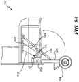
- the nose gear 302 includes a strut fitting 520 that is coupled to a gear strut 522, and a wheel 524 that is coupled to the gear strut 522. If the wheel 524 is "released", the gear strut 522 is rotated at the strut fitting 520 such that the gear strut 522 is in a vertical position and the wheel 524 is positioned to touch the ground. If the wheel 524 is "unreleased”, the gear strut 522 is rotated at the strut fitting 520 such that the gear strut 522 is in a horizontal position and the wheel 524 is positioned within a cavity of the nose gear 302.
- An aircraft information estimation system 502 is attached (e.g., coupled) to a housing of the nose gear 302.
- the aircraft information estimation system 502 includes the power source 101, the signal generator 102, the light source 104, the photoelectric sensor 112, the analog-to-digital converter 116, the signal offset processor 118, and the flight management processor 120.
- the output device 122 is included in the aircraft information estimation system 502.
- the structural member 108 is coupled to the strut fitting 520 and is subject to deformation based on the load, and the optical reflectors 110 are coupled to the structural member 108.
- the aircraft information estimation system 502 directs the light beam 132 towards the optical reflectors 110, and the light beam 132 is reflected along the optical reflectors 110 to the aircraft information estimation system 502 as the reflected light beam 134.
- Deformations in the structural member 108 under load are used to determine the location of the aircraft's 300 center-of-gravity (X CG ).
- deformations in the structural member 108 under load change (e.g., increase or decrease) the amount of time between the light beam 132 reaching the optical reflectors 110 and the reflected light beam 134 reaching the aircraft information estimation system 502 as opposed to if the structural member 108 is not under load.
- the change in the amount of time is based on additional lengths that the light beam 132 travels due to the deformations (e.g., which cause deflections) in the structural member 108.
- the main landing gear 304 includes a strut fitting 570 that is coupled to a gear strut 572, and a wheel 574 that is coupled to the gear strut 572. If the wheel 574 is "released", the gear strut 572 is rotated at the strut fitting 570 such that the gear strut 572 is in a vertical position and the wheel 574 is positioned to touch the ground. If the wheel 574 is "unreleased", the gear strut 572 is rotated at the strut fitting 570 such that the gear strut 572 is in a horizontal position and the wheel 574 is positioned within a cavity of the main landing gear 304.
- An aircraft information estimation system 552 is attached (e.g., coupled) to a housing of the main landing gear 304.
- the aircraft information estimation system 552 includes the power source 401, the signal generator 402, the light source 404, the photoelectric sensor 412, the analog-to-digital converter 416, the signal offset processor 418, and the flight management processor 120.
- the output device 122 is included in the aircraft information estimation system 552.
- the structural member 408 is coupled to the strut fitting 570 and is subject to deformation based on the load, and the optical reflectors 410 are coupled to the structural member 408.
- the aircraft information estimation system 552 directs the light beam 432 towards the optical reflectors 410, and the light beam 432 is reflected along the optical reflectors 410 to the aircraft information estimation system 552 as the reflected light beam 434.
- Deformations in the structural member 408 under load are used to determine the location of the aircraft's 300 center-of-gravity (X CG ) and to determine the weight of the aircraft 300.
- deformations in the structural member 408 under load change (e.g., increase or decrease) the amount of time between the light beam 432 reaching the optical reflectors 410 and the reflected light beam 434 reaching the aircraft information estimation system 552 as opposed to if the structural member 408 is not under load.
- the change in the amount of time is based on additional lengths that the light beam 432 travels due to the deformations (e.g., which cause deflections) in the structural member 408.
- a method 600 for estimating a location of a center-of-gravity of an aircraft is shown.
- the method 600 is performed by the one or more components of the system 100 of FIG. 1 , the system 200 of FIG. 2 , one or more components of the system 400 of FIG. 4 , or a combination thereof.
- the method 600 includes generating a first electrical signal, at 602.
- the signal generator 102 generates the first electrical signal 130 having the characteristics associated with the particular waveform 131.
- the first electrical signal 130 has a substantially identical phase as the particular waveform 131, a substantially identical period as the particular waveform 131, a substantially identical shape as the particular waveform 131, etc.
- the particular waveform 131 is a periodic waveform that has local maxima and local minima.
- the method 600 also includes generating a light beam based on the first electrical signal, at 604.
- the light beam is directed towards a structural member of an aircraft.
- the light source 104 generates the light beam 132 based on the first electrical signal 130.
- the light source 104 is a solid-state photon source that is capable of generating a consistent modulated signal having a relatively high degree of accuracy.
- the optical direction element 106 directs the light beam 132 towards the structural member 108.
- the method 600 also includes converting a reflected light beam to a second electrical signal, at 606.
- the reflected light beam corresponds to a portion of the light beam reflected from one or more optical reflectors coupled to the structural member.
- one or more mirrors e.g., optical reflectors 110
- the one or more optical reflectors 110 are coupled in such a manner that the reflected light beam 134 is directed towards the photoelectric sensor 112.
- the photoelectric sensor 112 converts the reflected light beam 134 into the second electrical signal 136.
- the second electrical signal 136 has a waveform with characteristics that are similar to the characteristics of the particular waveform 131 other than differences introduced due to the length of the optical path between the light source 104 and the photoelectric sensor 112.
- the method 600 also includes estimating a location of a center-of-gravity of the aircraft based on a timing difference between the first electrical signal and the second electrical signal, at 608.
- the analog-to-digital converter 116 converts the first electrical signal 130 into the first digital signal 138 and converts the second electrical signal 136 into the second digital signal 140.
- the signal offset processor 118 determines the timing differences ( ⁇ t 1-1 , ⁇ t 1-2 , ⁇ t 1-3 ) between the first digital signal 138 and the second digital signal 140, and the flight management processor 120 estimates the location of the center-of-gravity (X CG ) based on the average ( ⁇ T ) of the timing differences ( ⁇ t 1-1 , ⁇ t 1-2 , ⁇ t 1-3 ) over a time interval.
- the method 600 includes generating a third electrical signal.
- the method 600 may also include generating a second light beam based on the third electrical signal.
- the second light beam is directed towards a second structural member of the aircraft.
- the method 600 may also include converting a second reflected light beam to a fourth electrical signal.
- the second reflected light beam corresponds to a portion of the second light beam reflected from second one or more optical reflectors coupled to the second structural member.
- the method 600 may also include estimating a weight of the aircraft based on the timing difference and a second timing difference between the third electrical signal and the fourth electrical signal.
- the method 600 enables deformations in an aircraft's primary structure under load to be used to estimate the location of the aircraft's 300 center-of-gravity (X CG ), the aircraft's 300 weight (W gross ), or both.
- the location of the center-of-gravity (X CG ) and the weight (W gross ) may be presented to personnel associated with the aircraft 300 for safety checks. Additionally, operational flexibility and payload capability are increased due to weight estimations and center-of-gravity location estimations that are more accurate than manual estimations with curtailments.
- the location of the center-of-gravity (X CG ) can be used by a flight computer to set flight information.
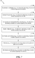
- FIGS. 7 and 8 examples of the disclosure are described in the context of an aircraft manufacturing and service method 700 as illustrated by the flow chart of FIG. 7 and the aircraft 300 as illustrated by the block diagram of FIG. 8 .
- the exemplary method 700 includes, at 702, specification and design of an aircraft, such as the aircraft 300 of FIG. 3 .
- the method 700 includes specifying the signal generator 102, the light source 104, the photoelectric sensor 112, the analog-to-digital converter 116, the signal offset processor 118, the flight management processor 120, and the output device 122.
- the method 700 includes material procurement.
- the method 700 may include procuring materials (such as materials for the signal generator 102, the light source 104, the photoelectric sensor 112, the analog-to-digital converter 116, the signal offset processor 118, the flight management processor 120, and the output device 122) for the aircraft information estimation system.
- materials such as materials for the signal generator 102, the light source 104, the photoelectric sensor 112, the analog-to-digital converter 116, the signal offset processor 118, the flight management processor 120, and the output device 122
- the method 700 includes, at 706, component and subassembly manufacturing and, at 708, system integration of the aircraft.
- the method 700 may include component and subassembly manufacturing (e.g., the signal generator 102, the light source 104, the photoelectric sensor 112, the analog-to-digital converter 116, the signal offset processor 118, the flight management processor 120, and the output device 122) of the aircraft information estimation system and system integration (e.g., coupling the components) of the aircraft information estimation system.
- the method 700 includes certification and delivery of the aircraft and, at 712, placing the aircraft in service.
- certification and delivery includes certifying the aircraft information estimation system. Placing the aircraft in service may also include placing aircraft information estimation system in service.
- the method 700 includes performing maintenance and service on the aircraft.
- the method 700 may include performing maintenance and service on the aircraft information estimation system.
- maintenance and service of the sensor data storage and analysis system may include replacing one or more of the signal generator 102, the light source 104, the photoelectric sensor 112, the analog-to-digital converter 116, the signal offset processor 118, the flight management processor 120, and the output device 122.
- the aircraft 300 is produced by at least a portion of the method 700 of FIG. 7 .
- the aircraft 800 includes an airframe 818, the structural member 108, a plurality of systems 820, and an interior 822.
- the plurality of systems 820 include one or more of a propulsion system 824, an electrical system 826, an environmental system 828, a hydraulic system 830, and a sensor system 832.
- the sensor system 832 includes one or more sensors onboard the aircraft 300 and configured to generate sensor data during operation of the aircraft 300.
- the sensor data indicates one or more parameter values of at least one operational parameter measured by the one or more sensors and one or more timestamps associated with the one or more parameter values.
- the aircraft 300 also includes an aircraft information estimation system 834.
- the aircraft information estimation system 834 includes the signal generator 102, the light source 104, the photoelectric sensor 112, the analog-to-digital converter 116, the signal offset processor 118, the flight management processor 120, and the output device 122.
- the aircraft information estimation system 834 may be used onboard a manned or unmanned aircraft (such as a satellite, a watercraft, or a land-based aircraft), or in a building or other structure.
- a manned or unmanned aircraft such as a satellite, a watercraft, or a land-based aircraft
- Apparatus and methods included herein may be employed during any one or more of the stages of the method 700 of FIG. 7 .
- components or subassemblies corresponding to production process 708 may be fabricated or manufactured in a manner similar to components or subassemblies produced while the aircraft 300 is in service, at 712 for example and without limitation.
- one or more apparatus implementations, method implementations, or a combination thereof may be utilized during the production stages (e.g., stages 702-710 of the method 700), for example, by substantially expediting assembly of or reducing the cost of the aircraft 300.
- one or more of apparatus implementations, method implementations, or a combination thereof may be utilized while the aircraft 300 is in service, at 300 for example and without limitation, to maintenance and service, at 714.
Landscapes
- General Physics & Mathematics (AREA)
- Physics & Mathematics (AREA)
- Engineering & Computer Science (AREA)
- Aviation & Aerospace Engineering (AREA)
- Health & Medical Sciences (AREA)
- Microelectronics & Electronic Packaging (AREA)
- Computer Hardware Design (AREA)
- Life Sciences & Earth Sciences (AREA)
- Chemical & Material Sciences (AREA)
- Analytical Chemistry (AREA)
- Biochemistry (AREA)
- General Health & Medical Sciences (AREA)
- Immunology (AREA)
- Pathology (AREA)
- Optical Radar Systems And Details Thereof (AREA)
Abstract
Description
- The present disclosure is related to a device that estimates a location of a center-of-gravity of an aircraft.
- A gross weight of an aircraft and a location of a center-of-gravity of the aircraft are estimated by an aircrew to ensure that the aircraft is compliant with regulations for safe operation. To accurately estimate the gross weight of the aircraft, the aircrew accounts for the gross weight of the aircraft when empty and unfueled, and the aircrew accounts for the weight of cargo and fuel. The center-of-gravity location is estimated based on the center-of-gravity location when the aircraft is empty and the approximate distribution of weight due to cargo and fuel. Because it is not practical to track the gross weight and the location of the center-of-gravity as conditions (e.g., loading and fueling) of the aircraft change, airlines apply curtailments (e.g., conservatisms) to an allowable gross weight and a center-of-gravity envelope to account for variations in the estimated gross weight and location of the center-of-gravity and the actual gross weight and location of the center-of-gravity.
- The curtailments subtract from the designed capabilities of the aircraft and reduce operational flexibility and payload flexibility. For example, the maximum amount of weight that is permitted to be loaded onto the aircraft is decreased due to the curtailments.
- According to one implementation of the present disclosure, an aircraft includes a structural member and a signal generator that is configured to generate a first electrical signal. The aircraft also includes a light source configured to generate a light beam based on the first electrical signal. The light source is also configured to direct the light beam towards a reflector attached to the structural member. The aircraft also includes a photoelectric sensor configured to receive a reflected light beam and convert the reflected light beam to a second electrical signal. The reflected light beam corresponds to a portion of the light beam that is reflected from one or more optical reflectors coupled to the structural member. The aircraft also includes circuitry configured to estimate a location of a center-of-gravity of the aircraft based on a timing difference between the first electrical signal and the second electrical signal.
- According to another implementation of the present disclosure, a method of obtaining aircraft information includes generating a first electrical signal. The method also includes generating a light beam based on the first electrical signal. The light beam is directed towards a structural member of an aircraft. The method also includes converting a reflected light beam to a second electrical signal. The reflected light beam corresponds to a portion of the light beam reflected from one or more optical reflectors coupled to the structural member. The method also includes estimating a location of a center-of-gravity of the aircraft based on a timing difference between the first electrical signal and the second electrical signal.
- According to another implementation of the present disclosure, a system includes a signal generator that is configured to generate a first electrical signal. The system also includes a light source configured to generate a light beam based on the first electrical signal. The light source is also configured to direct the light beam towards a structural member of an aircraft. The system also includes a photoelectric sensor configured to receive a reflected light beam and convert the reflected light beam to a second electrical signal. The reflected light beam corresponds to a portion of the light beam that is reflected from one or more optical reflectors coupled to the structural member. The system also includes circuitry configured to estimate a location of a center-of-gravity of the aircraft based on a timing difference between the first electrical signal and the second electrical signal.
- One advantage of the above-described implementation is that the location of a center-of-gravity of an aircraft (and in some implementations a weight of the aircraft) can be estimated using deformities in the aircraft's structures (e.g., a nose gear, a main landing gear, or both) as opposed to manually estimated by aircraft operators. As a result, operational flexibility and payload capability are increased due to weight estimations and center-of-gravity location estimations that are more accurate than manual estimations with curtailments. Thus, the maximum amount of weight that is permitted to be loaded onto the aircraft can be increased due curtailment reduction. Additionally, the features, functions, and advantages that have been described can be achieved independently in various implementations or may be combined in yet other implementations, further details of which are disclosed with reference to the following description and drawings.
-
-
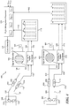
FIG. 1 is a diagram of a system that is operable to estimate a location of a center-of-gravity of an aircraft; -
FIG. 2 is a diagram of a system that is operable to determine timing differences between signals used to estimate the location of the center-of-gravity of the aircraft; -
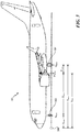
FIG. 3 is a diagram of the aircraft; -
FIG. 4 is a diagram of a system that is operable to estimate the location of the center-of-gravity of the aircraft and to estimate a weight of the aircraft; -
FIG. 5A is a diagram of an aircraft information estimation system integrated with a structural member of the aircraft; -
FIG. 5B is a diagram of an aircraft information estimation system integrated with another structural member of the aircraft; -
FIG. 6 is a flow chart of a method for estimating a location of a center-of-gravity of an aircraft; -
FIG. 7 is a flow chart of a method associated with an aircraft information estimation system; and -
FIG. 8 is a block diagram of an aircraft including an aircraft information estimation system. - Particular embodiments of the present disclosure are described below with reference to the drawings. In the description, common features are designated by common reference numbers throughout the drawings.
- The figures and the following description illustrate specific exemplary embodiments. It will be appreciated that those skilled in the art will be able to devise various arrangements that, although not explicitly described or shown herein, embody the principles described herein and are included within the scope of the claims that follow this description. Furthermore, any examples described herein are intended to aid in understanding the principles of the disclosure and are to be construed as being without limitation. As a result, this disclosure is not limited to the specific embodiments or examples described below, but by the claims and their equivalents.
- The techniques described herein enable a device to estimate a location of a center-of-gravity of an aircraft using load-based deformities in the aircraft's fuselage or the aircraft's wing structure. The load-based deformities in the aircraft's fuselage or the aircraft's wing structure change a distance along an optical path between a light source and a light receiver. For example, a signal generator generates an electrical signal having a periodic waveform, and the light source generates a light beam based on the electrical signal. The light beam is focused and directed towards an optical reflector attached to a structural member of the aircraft's nose gear. The optical reflector includes one or more mirrors (or multiple prisms) arranged to facilitate reflection of the light beam with minimal loss of signal intensity. The reflected light beam is refocused and received by a photoelectric sensor (e.g., the light receiver). The photoelectric sensor converts the reflected light beam into a second electrical signal. Offtakes from the first electrical signal and the second electrical signal are converted into corresponding digital signals by a multi-channel analog-to-digital signal converter. Time differences between local maxima of the digital signals are computed and averaged to determine a distance traveled by the light beam. As described below, based on the averaged time differences, the device determines the location of the center-of-gravity of the aircraft. Additionally, a similar device may be installed with respect to a main landing gear of an aircraft and may work in conjunction with the device to estimate the weight of the aircraft.
-
FIG. 1 is a diagram of asystem 100 that is operable to obtain aircraft information. For example, as described below, thesystem 100 is operable to estimate a location of a center-of-gravity (XCG) of an aircraft, such as anaircraft 300 depicted inFIG. 3 . Thesystem 100 includes apower source 101, asignal generator 102, alight source 104, aphotoelectric sensor 112, andadditional circuitry 190. Thecircuitry 190 includes an analog-to-digital converter 116, a signal offsetprocessor 118, aflight management processor 120, and anoutput device 122. According to one implementation, one or more components of thesystem 100 are integrated on anaircraft 300 within proximity of astructural member 108 on theaircraft 300. As a non-limiting example, thestructural member 108 corresponds to a portion of a nose gear of theaircraft 300, such as anose gear 302 depicted inFIG. 3 . As another non-limiting example, thestructural member 108 corresponds to a portion of a main landing gear of theaircraft 300, such as amain landing gear 304 depicted inFIG. 3 . - The
power source 101 is coupled to thesignal generator 102. According to one implementation, thepower source 101 is a direct current power source. As a non-limiting example, thepower source 101 includes a battery that provides power to thesignal generator 102. Thesignal generator 102 is configured to generate a firstelectrical signal 130 having characteristics of aparticular waveform 131. To illustrate, thesignal generator 102 includes awaveform generator 151 that generates theparticular waveform 131. Theparticular waveform 131 is a periodic waveform that has local maxima and local minima. The firstelectrical signal 130 has characteristics of theparticular waveform 131 and has an amplitude that is based on the amount of power provided by thepower source 101. For example, the firstelectrical signal 130 has a substantially identical phase as theparticular waveform 131, a substantially identical period as theparticular waveform 131, a substantially identical shape as theparticular waveform 131, etc. An amplitude of a local maximum associated with the firstelectrical signal 130 and an amplitude of a local minimum associated with the firstelectrical signal 130 are based on the amount of power provided by thepower source 101. For example, the amplitude of the local maximum increases as the amount of power provided by thepower source 101 increases. - The first
electrical signal 130 is provided to thelight source 104 and to the analog-to-digital converter 116. Thelight source 104 is configured to generate alight beam 132 based on the firstelectrical signal 130. In a particular implementation, thelight source 104 is a solid-state photon source that is capable of generating a consistent modulated signal having a relatively high degree of accuracy. According to one implementation, thelight source 104 includes anoptical direction element 106. For example, theoptical direction element 106 can include a reflector (e.g., a mirror, a prism, etc.) that directs thelight beam 132 towards a particular target. To illustrate, theoptical direction element 106 is configured to direct thelight beam 132 towards thestructural member 108. Thus, thelight source 104 generates thelight beam 132 and directs thelight beam 132 towards thestructural member 108. - One or more
optical reflectors 110 are coupled to thestructural member 108. Theoptical reflectors 110 include one or more mirrors, one or more prisms, or a combination thereof. Theoptical reflectors 110 are coupled to thestructural member 108 so that the reflectedlight beam 134 is directed towards thephotoelectric sensor 112 and so that an optical path distance between thelight source 104 and thephotoelectric sensor 112 is dependent on an amount of deformation of thestructural member 108. To illustrate, a first optical reflector may reflect thelight beam 132 towards a second optical reflector, and the second optical reflector may reflect thelight beam 132 towards thephotoelectric sensor 112 as the reflectedlight beam 134. Thus, the reflectedlight beam 134 corresponds to a portion of thelight beam 132 reflected from the one or moreoptical reflectors 110 coupled to thestructural member 108. According to one implementation, additional optical reflectors (not shown) are used to extend the optical path distance between thelight source 104 and thephotoelectric sensor 112. For example, multiple mirrors can be used to fold thelight beam 132 back and forth along the optical path to increase the optical path distance in order to increase measurement accuracy. - According to one implementation, the light beam 132 (e.g., an optical beam) is relayed through an optical medium. As a non-limiting example, the
light beam 132 may be relayed through a fiber optic connection with floating joints on both ends that isolates the optical medium from deformations in thestructural member 108. According to another implementation, thelight beam 132 is relayed via a line-of-sight connection. The line-of-sight connection can be augmented by deflectors and splitters. - The amount of deflection or deformation of the
structural member 108 is based on a load associated with the aircraft, such as theaircraft 300 ofFIG. 3 . As described below, deformations in thestructural member 108 under load can be used to determine the location of the aircraft's 300 center-of-gravity (XCG). To illustrate, deformations in thestructural member 108 under load changes (e.g., increases or decreases) the amount of time between thelight beam 132 reaching thestructural member 108 and the reflectedlight beam 134 being received at thephotoelectric sensor 112 as opposed to if thestructural member 108 is not under load. Specifically, the distance the light beams 132, 134 travel between thelight source 104 and thephotoelectric sensor 112 increases or decreases based the deformation of thestructural member 108. Thus, as the distance the light beams 132, 134 travel increases (or decreases), the amount of time required for the light to traverse between thelight source 104 and thephotoelectric sensor 112 also increases (or decreases) in direct correlation with the change in distance the light beams 132, 134 travel due to the deformations (e.g., which cause deflections) in thestructural member 108. - The
photoelectric sensor 112 is configured to receive the reflectedlight beam 134. Although thephotoelectric sensor 112 is shown to include anoptical direction element 114 inFIG. 1 , in other implementations, theoptical direction element 114 is separate from thephotoelectric sensor 112. Theoptical direction element 114 can include a reflector (e.g., a mirror, a prism, etc.) that directs thelight beam 132 towards a particular target. To illustrate, theoptical direction element 114 is configured to direct the reflectedlight beam 134 towards thephotoelectric sensor 112. After reception of the reflectedlight beam 134, thephotoelectric sensor 112 is configured to convert the reflectedlight beam 134 into a secondelectrical signal 136. The secondelectrical signal 136 has a waveform with characteristics that are similar to the characteristics of theparticular waveform 131 other than differences introduced due to the length of the optical path between thelight source 104 and thephotoelectric sensor 112. For example, the secondelectrical signal 136 has a substantially identical period as theparticular waveform 131, a substantially identical shape as theparticular waveform 131, etc. According to one implementation, the photoelectric sensor 112 (e.g., a high-sensitivity photoelectric sensor) has a relatively high refresh rate and has a high signal-to-noise ratio circuit that enables identification and measurement of signal property changes between the firstelectrical signal 130 and the secondelectrical signal 136. Because theelectrical signals electrical signal 130, the secondelectrical signal 136, or both. The secondelectric signal 136 is provided to the analog-to-digital converter 116. - The analog-to-
digital converter 116 is configured to convert the first electrical signal 130 (e.g., an analog signal) into a firstdigital signal 138. The firstdigital signal 138 has properties associated with the waveform of the firstelectrical signal 130. Additionally, the analog-to-digital converter 116 is configured to convert the second electrical signal 136 (e.g., an analog signal) into a seconddigital signal 140. The seconddigital signal 140 has properties associated with the waveform of the secondelectrical signal 136. The firstdigital signal 138 and the seconddigital signal 140 are provided to the signal offsetprocessor 118. - The signal offset
processor 118 is configured to determine timing differences (Δt1-1, Δt1-2, Δt1-3) between the firstdigital signal 138 and the seconddigital signal 140. Each timing difference (Δt1-1, Δt1-2, Δt1-3) corresponds to an amount of time between a local maximum of the firstdigital signal 138 and a corresponding local maximum of the seconddigital signal 140. The firstdigital signal 138 is illustrated within the signal offsetprocessor 118 using a dashed-line with relatively large dashes, and the seconddigital signal 140 is illustrated within the signal offsetprocessor 118 using a dashed-line with smaller dashes. The signal offsetprocessor 118 is configured to determine a first time, such as a first time 206 inFIG. 2 , that the firstdigital signal 138 attains a local maximum. The signal offsetprocessor 118 is also configured to determine a corresponding second time, such as asecond time 212 inFIG. 2 , that the seconddigital signal 140 attains a local maximum. A first timing difference (Δt1-1) corresponds to the amount of time (e.g., the difference) between the first time and the second time. In a similar manner, a timing difference (Δt1-2) corresponds to the amount of time between the next local maximum of thedigital signals digital signals electrical signal 130 and conversion of the reflectedlight beam 134 is based on an amount of deflection of thestructural member 108 due a load associated with theaircraft 300. Operations of the signal offsetprocessor 118 are described in greater detail with respect toFIG. 2 . - Referring to
FIG. 2 , aflow chart 200 for determining the timing differences (Δt1-1, Δt1-2, Δt1-3) is shown. Operations illustrated inFIG. 2 are performed by the signal offsetprocessor 118 ofFIG. 1 . The signal offsetprocessor 118 is operable to identify the first time 206 that the firstdigital signal 138 attains a local maximum and to identify the correspondingsecond time 212 that the seconddigital signal 140 attains a local maximum. Thus, signal processing operations on thedigital signals digital signals signals - The first
digital signal 138 is provided to aprocessing block 202 at a current test time (t1=0). Theprocessing block 202 is configured to sample the firstdigital signal 138 at the current test time (t1=0). Adecision block 204 compares the amplitude So(t1) of the firstdigital signal 138 at the current test time (t1) to the amplitude So(t1-Δt1) of the firstdigital signal 138 at a previous test time (t1-Δt1). If the amplitude So(t1) of the firstdigital signal 138 is greater than the amplitude So(t1-Δt1) of the firstdigital signal 138 at a previously sampled test time (t1-Δt1), the processing block 202 samples the firstdigital signal 138 at an updated current test time (t1=t1+Δt1). The process is repeated until thedecision block 204 determines the amplitude So(t1) of the firstdigital signal 138 at the current test time (t1) is not greater than the amplitude So(t1-Δt1) of the firstdigital signal 138 at a previously sampled test time (t1-Δt1). The current test time (t1) is stored as the first time 206 based on a determination that the amplitude So(t1) is not greater than (e.g., less than or equal to) the amplitude So(t1-Δt1), indicating that the firstdigital signal 138 has a attained a local maximum. - In a similar manner, the second
digital signal 140 is provided to aprocessing block 208 at a current test time (t2=0). Theprocessing block 208 is configured to sample the seconddigital signal 140 at the current test time (t2=0). Adecision block 210 compares the amplitude Si(t2) of the seconddigital signal 140 at the current test time (t2) to the amplitude Si(t2-Δt2) of the seconddigital signal 140 at a previous test time (t2-Δt2). If the amplitude Si(t2) of the seconddigital signal 140 is greater than the amplitude Si(t2-Δt2) of the seconddigital signal 140 at a previously sampled test time (t2-Δt2), the processing block 208 samples the seconddigital signal 140 at an updated current test time (t2=t2+Δt2). The process is repeated until thedecision block 210 determines the amplitude Si(t2) of the seconddigital signal 140 at the current test time (t2) is not greater than the amplitude Si(t2-Δt2) of the seconddigital signal 140 at a previously sampled test time (t2-Δt2). The current test time (t2) is stored as thesecond time 212 based on a determination that the amplitude Si(t2) is not greater than (e.g., less than or equal to) the amplitude Si(t2-Δt2), indicating that the seconddigital signal 140 has a attained a local maximum. - At
block 214, thesystem 200 determines the first timing difference (Δt1-1) based on the difference (e.g., the absolute value of the difference) of the first time 206 and thesecond time 212. The process described with respect toFIG. 2 is repeated to determine the other timing differences (Δt1-2, Δt1-3). Thus, thesystem 200 receives and processes thedigital signals - Referring back to
FIG. 1 , the signal offsetprocessor 118 is configured to generate a timing offsetsignal 142 that indicates the timing differences (Δt1-1, Δt1-2, Δt1-3). The timing offsetsignal 142 is provided to theflight management processor 120. Theflight management processor 120 is configured to estimate the location of the center-of-gravity (XCG) of theaircraft 300 based on the timing differences (Δt1-1, Δt1-2, Δt1-3) indicated by the timing offsetsignal 142 and other information associated with theaircraft 300. Operations of theflight management processor 120 are described in conjunction with theaircraft 300 depicted inFIG. 3 . - A reaction force (Nnose) of the nose gear 302 (e.g., the nose landing gear) is determined (e.g., calculated) by the
flight management processor 120 based on the timing differences (Δt1-1, Δt1-2, Δt1-3). To illustrate, theflight management processor 120 is configured to determine an average (ΔT ) of the timing differences (Δt1-1, Δt1-2, Δt1-3) over a time interval. Based on the average (ΔT ), theflight management processor 120 is configured to determine the reaction force (Nnose). For example, theflight management processor 120 may use a look-up table to determine the reaction force (Nnose) based on the average (ΔT ). To illustrate, for a particular average (ΔT ), a corresponding value of a reaction force (Nnose) is listed in the look-up table and stored in memory. The value of the reaction force (Nnose) may be determined via interpolation if there is not a value that corresponds to the particular average (ΔT ). According to one implementation, thenose gear 302 is thestructural member 108. - A location (Xnose) of the
nose gear 302 along a horizontal axis relative to a reference point 306 (e.g., the front of the aircraft 300) is provided to theflight management processor 120, a location (Xmain) of themain landing gear 304 along the horizontal axis relative to thereference point 306 is provided to theflight management processor 120, and a gross weight vector (Wgross) of theaircraft 300 indicating the ramp weight of theaircraft 300 is provided to theflight management processor 120. Based on the additional information, theflight management processor 120 can estimate the location of the center-of-gravity (XCG) using the following equation:
- In
FIG. 3 , Dnose indicates the distance between thenose gear 302 and the center-of-gravity (XCG), and Dmain indicates the distance betweenmain landing gear 304 and the center-of-gravity (XCG). - According to another implementation, the average (Δ
T ) of the timing differences (Δt1-1, Δt1-2, Δt1-3) and the weight of the aircraft 300 (e.g., the gross weight vector (Wgross)) are inputs to a look-up table used to estimate the location of the center of gravity (XCG). For example, theflight management processor 120 is configured to use a table lookup procedure to relate the location of the center of gravity (XCG) to the gross weight vector (Wgross) and the average (ΔT ) of the timing differences (Δt1-1, Δt1-2, Δt1-3). According to some implementations, theflight management processor 120 interpolates between tabulated values of the look-up table if the gross weight vector (Wgross) and the average (ΔT ) of the timing differences (Δt1-1, Δt1-2, Δt1-3) are not in the look-up table. According to another implementation, the average (ΔT ) of the timing differences (Δt1-1, Δt1-2, Δt1-3) and the gross weight vector (Wgross) are inputs to an empirical function (or semi-empirical function) that is used to solve for the location of the center of gravity (XCG). For example, the empirical function may be expressed as:
- The location of the center-of-gravity (XCG) is provided to the
output device 122 to inform on-board crew, ground crew technicians, or dispatchers of aircraft conditions. As a non-limiting example, theoutput device 122 may generate a tip-up alarm to indicate that the location of the center-of-gravity (XCG) is too far towards the rear of theaircraft 300, which may result in theaircraft 300 nose tipping up. As another example, the location of the center-of-gravity can be used by theflight management processor 120 to set (or record) flight information, such as a trim setting. As another non-limiting example, theoutput device 122 may correspond to a cockpit display to inform the on-board crew (e.g., the pilots) of the location of the center-of-gravity (XCG). As another non-limiting example, theoutput device 122 may correspond to a remote device to inform the dispatch operators of the location of the center-of-gravity (XCG). Thus, theoutput device 122 provides graphical data, numerical data, or both, to the flight crew and the ground crew. - The techniques described with respect to
FIGS. 1-3 enable deformations in an aircraft's primary structure under load to be used to estimate the location of the aircraft's center-of-gravity (XCG). For example, deformations in thestructural member 108 under load change (e.g., increase) the amount of time between generation of the firstelectrical signal 130 and conversion of the reflectedlight beam 134 as opposed to if thestructural member 108 is not under load. The change in the amount of time is based on changes in the distance that thelight beam 132 travels due to the deformations in thestructural member 108. Using the change in the amount of time and the aircraft's weight, theflight management processor 120 estimates the location of the aircraft's center-of-gravity (XCG). - Certain ramp slopes may vary as much as a two-degree incline from level or a two-degree decline from level. According to some implementations, one or more measuring units (e.g., onboard gyroscopes) are configured to measure the pitch attitude of the
aircraft 300 to enable thesystem 100 to determine the location of the center-of-gravity (XCG) on a variety of ramp slopes. Additionally, the temperature can affect deflection of thestructural member 108 and can affect optical path length. Thus, according to some implementations, temperature-sensors are configured to measure the ambient temperature near theaircraft 300, and the measured temperature is accounted for during determination of the location of the center-of-gravity (XCG). Adjustments to the location of the center-of-gravity (XCG) based on the measured temperature can be determined using a look-up table. To illustrate, for a particular temperature, a corresponding adjustment to the location of the center-of-gravity (XCG) is listed in the look-up table and stored in memory. The adjustment may be determined via interpolation if there is not a listed adjustment that corresponds to the particular temperature. Alternatively, the adjustments to the location of the center-of-gravity (XCG) may be determined using a mathematical function. -
FIG. 4 is a diagram of anothersystem 400 that is operable to obtain aircraft information. Thesystem 400 is operable to estimate the location of the center-of-gravity of an aircraft (e.g., the aircraft 300) and operable to estimate a weight of the aircraft. Thesystem 400 includes components that are included insystem 100 ofFIG. 1 , such as thepower source 101, thesignal generator 102, thelight source 104, thestructural member 108, thephotoelectric sensor 112, the analog-to-digital converter 116, and the signal offsetprocessor 118. The components operate in a substantially similar manner as described above. For example, the components 101-118 operate to generate the timing offsetsignal 142 that indicates the timing differences (Δt1-1, Δt1-2, Δt1-3). Thesystem 400 also includes apower source 401, asignal generator 402, alight source 404, astructural member 408, aphotoelectric sensor 412, an analog-to-digital converter 416, and a signal offsetprocessor 418. According to the illustration inFIG. 4 , thestructural member 108 corresponds to a portion of thenose gear 302 ofFIG. 3 , and thestructural member 408 corresponds to a portion of themain landing gear 304 ofFIG. 3 . - The
power source 401 is coupled to thesignal generator 402. According to one implementation, thepower source 401 is a direct current power source. As a non-limiting example, thepower source 401 includes a battery that provides power to thesignal generator 402. Thesignal generator 402 is configured to generate a thirdelectrical signal 430 having aparticular waveform 431. To illustrate, thesignal generator 402 includes awaveform generator 451 that generates theparticular waveform 431. Theparticular waveform 431 is a periodic waveform that has local maxima and local minima. The thirdelectrical signal 430 has characteristics of theparticular waveform 431 and has an amplitude that is based on the amount of power provided by thepower source 401. For example, the thirdelectrical signal 430 has a substantially identical phase as theparticular waveform 431, a substantially identical period as theparticular waveform 431, a substantially identical shape as theparticular waveform 431, etc. An amplitude of a local maximum associated with the thirdelectrical signal 430 and an amplitude of a local minimum associated with the thirdelectrical signal 430 is based on the amount of power provided by thepower source 401. For example, the amplitude of the local maximum increases as the amount of power provided by thepower source 401 increases. - The third
electrical signal 430 is provided to thelight source 404 and to the analog-to-digital converter 416. Thelight source 404 is configured to generate a secondlight beam 432 based on the thirdelectrical signal 430. According to one implementation, thelight source 404 includes anoptical direction element 406. Theoptical direction element 406 is configured to direct the secondlight beam 432 towards thestructural member 408. Thus, thelight source 404 generates the secondlight beam 432 and directs the secondlight beam 432 towards thestructural member 408. - One or more
optical reflectors 410 are coupled to thestructural member 408. Theoptical reflectors 410 are coupled to thestructural member 408 so that the second reflectedlight beam 434 is directed towards thephotoelectric sensor 412 and so that an optical path distance between thelight source 404 and thephotoelectric sensor 412 is dependent on an amount of deformation of thestructural member 408. To illustrate, a first optical reflector (of the optical reflectors 410) may reflect the secondlight beam 432 towards a second optical reflector (of the optical reflectors 410), and the second optical reflector may reflect the secondlight beam 432 towards thephotoelectric sensor 412 as the second reflectedlight beam 434. Thus, the second reflectedlight beam 434 corresponds to a portion of the secondlight beam 432 reflected from the plurality ofoptical reflectors 410 coupled to thestructural member 408. According to one implementation, additional optical reflectors (not shown) are to extend the optical path distance between thelight source 404 and thephotoelectric sensor 412. - The
photoelectric sensor 412 is configured to receive the second reflectedlight beam 434. Although thephotoelectric sensor 412 is shown to include anoptical direction element 414 inFIG. 4 , in other implementations, theoptical direction element 414 is separate from thephotoelectric sensor 412. Theoptical direction element 414 is configured to direct the second reflectedlight beam 434 towards thephotoelectric sensor 412. After reception of the second reflectedlight beam 434, thephotoelectric sensor 412 is configured to convert the second reflectedlight beam 434 into a fourthelectrical signal 436. The fourthelectrical signal 436 has a waveform with characteristics that are similar to the characteristics of theparticular waveform 431 other than differences introduced due to the length of the optical path between thelight source 404 and thephotoelectric sensor 412. For example, the fourthelectrical signal 436 has a substantially identical phase as theparticular waveform 431, a substantially identical period as theparticular waveform 431, a substantially identical shape as theparticular waveform 431, etc. The fourthelectric signal 436 is provided to the analog-to-digital converter 416. - The analog-to-
digital converter 416 is configured to convert the third electrical signal 430 (e.g., an analog signal) into a thirddigital signal 438. The thirddigital signal 438 has properties associated with the waveform of the thirdelectrical signal 430. Additionally, the analog-to-digital converter 416 is configured to convert the fourth electrical signal 436 (e.g., an analog signal) into a fourthdigital signal 440. The fourthdigital signal 440 has properties associated with the waveform of the fourthelectrical signal 436. The thirddigital signal 438 and the fourthdigital signal 440 are provided to the signal offsetprocessor 418. - The signal offset
processor 418 operates in a similar manner as the signal offsetprocessor 118. For example, the signal offsetprocessor 418 is configured to determine timing differences (Δt2-1, Δt2-2, Δt2-3) between the thirddigital signal 438 and the fourthdigital signal 440. To illustrate, the signal offsetprocessor 418 is configured to determine a third time that the thirddigital signal 438 attains a local maximum and to determine a fourth time that the fourthdigital signal 440 attains a corresponding local maximum. A timing difference (Δt2-1) corresponds to the amount of time (e.g., the difference) between the third time and the fourth time. In a similar manner, a timing difference (Δt2-2) corresponds to the amount of time between the next local maximum of thedigital signals digital signals electrical signal 430 and conversion of the second reflectedlight beam 434 is based on an amount of deflection of thestructural member 408 due the load associated with theaircraft 300. The signal offsetprocessor 418 is configured to generate a timing offsetsignal 442 that indicates the timing differences (Δt2-1, Δt2-2, Δt2-3). The timing offsetsignal 442 is provided to theflight management processor 120. - The
flight management processor 120 is configured to estimate the location of the center-of-gravity (XCG) of theaircraft 300 and the weight (Wgross) of theaircraft 300 based on the timing differences (Δt1-1, Δt1-2, Δt1-3) indicated by the timing offsetsignal 142, the timing differences (Δt2-1, Δt2-2, Δt2-3) indicated by the timing offsetsignal 442, and other information associated with theaircraft 300. Prior to estimation of the center-of-gravity (XCG) and the weight (Wgross), theflight management processor 120 determines a reaction force (Nmain) of the main landing gear 304 (e.g., the structural member 408). The reaction force (Nnose) of the nose gear 302 (e.g., the structural member 108) is determined in a similar manner as described with respect toFIG. 1 . The reaction force (Nmain) of themain landing gear 304 is determined (e.g., calculated) by theflight management processor 120 based on the timing differences (Δt2-1, Δt2-2, Δt2-3). To illustrate, theflight management processor 120 is configured to determine an average (ΔT ) of the timing differences (Δt2-1, Δt2-2, Δt2-3) over a time interval. Based on the average (ΔT ), theflight management processor 120 is configured to determine the reaction force (Nmain). For example, theflight management processor 120 may use a look-up table to determine the reaction force (Nmain) based on the average (ΔT ). To illustrate, for a particular average (ΔT ), a corresponding value of a reaction force (Nmain) is listed in the look-up table and stored in memory. The value of the reaction force (Nmain) may be determined via interpolation if there is not a value that corresponds to the particular average (ΔT ). - The
flight management processor 120 is configured to estimate the weight (Wgross) of theaircraft 300 based on the reaction force (Nnose) of thenose gear 302 and the reaction force (Nmain) of themain landing gear 304. For example, the weight (Wgross) of theaircraft 300 is determined using the following equation:
- Additionally, the
flight management processor 120 is configured to estimate the location of the center-of-gravity (XCG) of theaircraft 300. To estimate the location of the center-of-gravity (XCG) of theaircraft 300, the location (Xnose) of thenose gear 302 and the location (Xmain) of themain landing gear 304 are provided to theflight management processor 120. Based on the additional information, theflight management processor 120 may estimate the location of the center-of-gravity (XCG) using the following equation:
- In addition to the location of the center-of-gravity (XCG), the weight (Wgross) is provided to the
output device 122 to inform on-board crew, ground crew, technicians, or dispatchers of weight conditions of theaircraft 300. Based on the weight conditions, the on-board crew and the ground crew may be notified byoutput device 122 whether theaircraft 300 is too heavy. - Thus, the techniques described with respect to
FIG. 4 enable deformations in an aircraft's primary structure under load to be used to estimate the location of the aircraft's 300 center-of-gravity (XCG) and weight (Wgross). The location of the center-of-gravity (XCG) and the weight (Wgross) may be presented to personnel associated with theaircraft 300 for safety checks. To illustrate, the location of the center-of-gravity (XCG) can be used byflight management processor 120 to set flight information, such as a trim setting. Additionally, the weight of theaircraft 300 can be used to estimate fuel consumption of the flight. Additionally, operational flexibility and payload capability are increased due to weight estimations and center-of-gravity location estimations that are more accurate than manual estimations with curtailments. - Referring to
FIG. 5A , a diagram of thenose gear 302 is shown. Thenose gear 302 includes a strut fitting 520 that is coupled to agear strut 522, and awheel 524 that is coupled to thegear strut 522. If thewheel 524 is "released", thegear strut 522 is rotated at the strut fitting 520 such that thegear strut 522 is in a vertical position and thewheel 524 is positioned to touch the ground. If thewheel 524 is "unreleased", thegear strut 522 is rotated at the strut fitting 520 such that thegear strut 522 is in a horizontal position and thewheel 524 is positioned within a cavity of thenose gear 302. - An aircraft
information estimation system 502 is attached (e.g., coupled) to a housing of thenose gear 302. The aircraftinformation estimation system 502 includes thepower source 101, thesignal generator 102, thelight source 104, thephotoelectric sensor 112, the analog-to-digital converter 116, the signal offsetprocessor 118, and theflight management processor 120. According to one implementation, theoutput device 122 is included in the aircraftinformation estimation system 502. - The
structural member 108 is coupled to the strut fitting 520 and is subject to deformation based on the load, and theoptical reflectors 110 are coupled to thestructural member 108. The aircraftinformation estimation system 502 directs thelight beam 132 towards theoptical reflectors 110, and thelight beam 132 is reflected along theoptical reflectors 110 to the aircraftinformation estimation system 502 as the reflectedlight beam 134. - Deformations in the
structural member 108 under load are used to determine the location of the aircraft's 300 center-of-gravity (XCG). To illustrate, deformations in thestructural member 108 under load change (e.g., increase or decrease) the amount of time between thelight beam 132 reaching theoptical reflectors 110 and the reflectedlight beam 134 reaching the aircraftinformation estimation system 502 as opposed to if thestructural member 108 is not under load. The change in the amount of time is based on additional lengths that thelight beam 132 travels due to the deformations (e.g., which cause deflections) in thestructural member 108. - Referring to
FIG. 5B , a diagram of themain landing gear 304 is shown. Themain landing gear 304 includes a strut fitting 570 that is coupled to agear strut 572, and awheel 574 that is coupled to thegear strut 572. If thewheel 574 is "released", thegear strut 572 is rotated at the strut fitting 570 such that thegear strut 572 is in a vertical position and thewheel 574 is positioned to touch the ground. If thewheel 574 is "unreleased", thegear strut 572 is rotated at the strut fitting 570 such that thegear strut 572 is in a horizontal position and thewheel 574 is positioned within a cavity of themain landing gear 304. - An aircraft
information estimation system 552 is attached (e.g., coupled) to a housing of themain landing gear 304. The aircraftinformation estimation system 552 includes thepower source 401, thesignal generator 402, thelight source 404, thephotoelectric sensor 412, the analog-to-digital converter 416, the signal offsetprocessor 418, and theflight management processor 120. According to one implementation, theoutput device 122 is included in the aircraftinformation estimation system 552. - The
structural member 408 is coupled to the strut fitting 570 and is subject to deformation based on the load, and theoptical reflectors 410 are coupled to thestructural member 408. The aircraftinformation estimation system 552 directs thelight beam 432 towards theoptical reflectors 410, and thelight beam 432 is reflected along theoptical reflectors 410 to the aircraftinformation estimation system 552 as the reflectedlight beam 434. - Deformations in the
structural member 408 under load are used to determine the location of the aircraft's 300 center-of-gravity (XCG) and to determine the weight of theaircraft 300. To illustrate, deformations in thestructural member 408 under load change (e.g., increase or decrease) the amount of time between thelight beam 432 reaching theoptical reflectors 410 and the reflectedlight beam 434 reaching the aircraftinformation estimation system 552 as opposed to if thestructural member 408 is not under load. The change in the amount of time is based on additional lengths that thelight beam 432 travels due to the deformations (e.g., which cause deflections) in thestructural member 408. - Referring to
FIG. 6 , amethod 600 for estimating a location of a center-of-gravity of an aircraft is shown. Themethod 600 is performed by the one or more components of thesystem 100 ofFIG. 1 , thesystem 200 ofFIG. 2 , one or more components of thesystem 400 ofFIG. 4 , or a combination thereof. - The
method 600 includes generating a first electrical signal, at 602. For example, referring toFIG. 1 , thesignal generator 102 generates the firstelectrical signal 130 having the characteristics associated with theparticular waveform 131. To illustrate, the firstelectrical signal 130 has a substantially identical phase as theparticular waveform 131, a substantially identical period as theparticular waveform 131, a substantially identical shape as theparticular waveform 131, etc. Theparticular waveform 131 is a periodic waveform that has local maxima and local minima. - The
method 600 also includes generating a light beam based on the first electrical signal, at 604. The light beam is directed towards a structural member of an aircraft. For example, referring toFIG. 1 , thelight source 104 generates thelight beam 132 based on the firstelectrical signal 130. In a particular implementation, thelight source 104 is a solid-state photon source that is capable of generating a consistent modulated signal having a relatively high degree of accuracy. Theoptical direction element 106 directs thelight beam 132 towards thestructural member 108. - The
method 600 also includes converting a reflected light beam to a second electrical signal, at 606. The reflected light beam corresponds to a portion of the light beam reflected from one or more optical reflectors coupled to the structural member. For example, referring toFIG. 1 , one or more mirrors (e.g., optical reflectors 110) are coupled to thestructural member 108 to reflect thelight beam 132 along thestructural member 108 as the reflectedlight beam 134. The one or moreoptical reflectors 110 are coupled in such a manner that the reflectedlight beam 134 is directed towards thephotoelectric sensor 112. Thephotoelectric sensor 112 converts the reflectedlight beam 134 into the secondelectrical signal 136. The secondelectrical signal 136 has a waveform with characteristics that are similar to the characteristics of theparticular waveform 131 other than differences introduced due to the length of the optical path between thelight source 104 and thephotoelectric sensor 112. - The
method 600 also includes estimating a location of a center-of-gravity of the aircraft based on a timing difference between the first electrical signal and the second electrical signal, at 608. For example, the analog-to-digital converter 116 converts the firstelectrical signal 130 into the firstdigital signal 138 and converts the secondelectrical signal 136 into the seconddigital signal 140. The signal offsetprocessor 118 determines the timing differences (Δt1-1, Δt1-2, Δt1-3) between the firstdigital signal 138 and the seconddigital signal 140, and theflight management processor 120 estimates the location of the center-of-gravity (XCG) based on the average (ΔT ) of the timing differences (Δt1-1, Δt1-2, Δt1-3) over a time interval. - According to one implementation, the
method 600 includes generating a third electrical signal. Themethod 600 may also include generating a second light beam based on the third electrical signal. The second light beam is directed towards a second structural member of the aircraft. Themethod 600 may also include converting a second reflected light beam to a fourth electrical signal. The second reflected light beam corresponds to a portion of the second light beam reflected from second one or more optical reflectors coupled to the second structural member. Themethod 600 may also include estimating a weight of the aircraft based on the timing difference and a second timing difference between the third electrical signal and the fourth electrical signal. - The
method 600 enables deformations in an aircraft's primary structure under load to be used to estimate the location of the aircraft's 300 center-of-gravity (XCG), the aircraft's 300 weight (Wgross), or both. The location of the center-of-gravity (XCG) and the weight (Wgross) may be presented to personnel associated with theaircraft 300 for safety checks. Additionally, operational flexibility and payload capability are increased due to weight estimations and center-of-gravity location estimations that are more accurate than manual estimations with curtailments. The location of the center-of-gravity (XCG) can be used by a flight computer to set flight information. - Referring to
FIGS. 7 and8 , examples of the disclosure are described in the context of an aircraft manufacturing andservice method 700 as illustrated by the flow chart ofFIG. 7 and theaircraft 300 as illustrated by the block diagram ofFIG. 8 . - Referring to
FIG. 7 , a flowchart of an illustrative example of a m300ethod associated with an aircraft information estimation system is shown and designated 700. During pre-production, theexemplary method 700 includes, at 702, specification and design of an aircraft, such as theaircraft 300 ofFIG. 3 . During the specification and design of the aircraft, themethod 700 includes specifying thesignal generator 102, thelight source 104, thephotoelectric sensor 112, the analog-to-digital converter 116, the signal offsetprocessor 118, theflight management processor 120, and theoutput device 122. At 704, themethod 700 includes material procurement. For example, themethod 700 may include procuring materials (such as materials for thesignal generator 102, thelight source 104, thephotoelectric sensor 112, the analog-to-digital converter 116, the signal offsetprocessor 118, theflight management processor 120, and the output device 122) for the aircraft information estimation system. - During production, the
method 700 includes, at 706, component and subassembly manufacturing and, at 708, system integration of the aircraft. Themethod 700 may include component and subassembly manufacturing (e.g., thesignal generator 102, thelight source 104, thephotoelectric sensor 112, the analog-to-digital converter 116, the signal offsetprocessor 118, theflight management processor 120, and the output device 122) of the aircraft information estimation system and system integration (e.g., coupling the components) of the aircraft information estimation system. At 710, themethod 700 includes certification and delivery of the aircraft and, at 712, placing the aircraft in service. In some implementations, certification and delivery includes certifying the aircraft information estimation system. Placing the aircraft in service may also include placing aircraft information estimation system in service. While in service, the aircraft may be scheduled for routine maintenance and service (which may also include modification, reconfiguration, refurbishment, and so on). At 714, themethod 700 includes performing maintenance and service on the aircraft. Themethod 700 may include performing maintenance and service on the aircraft information estimation system. For example, maintenance and service of the sensor data storage and analysis system may include replacing one or more of thesignal generator 102, thelight source 104, thephotoelectric sensor 112, the analog-to-digital converter 116, the signal offsetprocessor 118, theflight management processor 120, and theoutput device 122. - Referring to
FIG. 8 , a block diagram of an illustrative implementation of theaircraft 300 that includes components of an aircraft information estimation system is shown. In at least one implementation, theaircraft 300 is produced by at least a portion of themethod 700 ofFIG. 7 . As shown inFIG. 8 , theaircraft 800 includes anairframe 818, thestructural member 108, a plurality ofsystems 820, and an interior 822. Examples of the plurality ofsystems 820 include one or more of apropulsion system 824, anelectrical system 826, anenvironmental system 828, ahydraulic system 830, and asensor system 832. Thesensor system 832 includes one or more sensors onboard theaircraft 300 and configured to generate sensor data during operation of theaircraft 300. The sensor data indicates one or more parameter values of at least one operational parameter measured by the one or more sensors and one or more timestamps associated with the one or more parameter values. - The
aircraft 300 also includes an aircraftinformation estimation system 834. The aircraftinformation estimation system 834 includes thesignal generator 102, thelight source 104, thephotoelectric sensor 112, the analog-to-digital converter 116, the signal offsetprocessor 118, theflight management processor 120, and theoutput device 122. - Any number of other systems may be included in the
aircraft 300. Although an aerospace example is shown, the present disclosure may be applied to other industries. For example, the aircraftinformation estimation system 834 may be used onboard a manned or unmanned aircraft (such as a satellite, a watercraft, or a land-based aircraft), or in a building or other structure. - Apparatus and methods included herein may be employed during any one or more of the stages of the
method 700 ofFIG. 7 . For example, components or subassemblies corresponding toproduction process 708 may be fabricated or manufactured in a manner similar to components or subassemblies produced while theaircraft 300 is in service, at 712 for example and without limitation. Also, one or more apparatus implementations, method implementations, or a combination thereof may be utilized during the production stages (e.g., stages 702-710 of the method 700), for example, by substantially expediting assembly of or reducing the cost of theaircraft 300. Similarly, one or more of apparatus implementations, method implementations, or a combination thereof may be utilized while theaircraft 300 is in service, at 300 for example and without limitation, to maintenance and service, at 714. - The illustrations of the examples described herein are intended to provide a general understanding of the structure of the various implementations. The illustrations are not intended to serve as a complete description of all of the elements and features of apparatus and systems that utilize the structures or methods described herein. Many other implementations may be apparent to those of skill in the art upon reviewing the disclosure. Other implementations may be utilized and derived from the disclosure, such that structural and logical substitutions and changes may be made without departing from the scope of the disclosure. For example, method operations may be performed in a different order than shown in the figures or one or more method operations may be omitted. Accordingly, the disclosure and the figures are to be regarded as illustrative rather than restrictive.
- Moreover, although specific examples have been illustrated and described herein, it should be appreciated that any subsequent arrangement designed to achieve the same or similar results may be substituted for the specific implementations shown. This disclosure is intended to cover any and all subsequent adaptations or variations of various implementations. Combinations of the above implementations, and other implementations not specifically described herein, will be apparent to those of skill in the art upon reviewing the description.
- Further, the disclosure comprises embodiments according to the following clauses:
- Clause 1. A system comprising:
- a signal generator configured to generate a first electrical signal;
- a light source configured to:
- generate a light beam based on the first electrical signal; and
- direct the light beam towards a structural member of an aircraft;
- a photoelectric sensor configured to:
- receive a reflected light beam, the reflected light beam corresponding to a portion of the light beam reflected from one or more optical reflectors coupled to the structural member; and
- convert the reflected light beam to a second electrical signal; and
- circuitry configured to estimate a location of a center-of-gravity of the aircraft based on a timing difference between the first electrical signal and the second electrical signal.
- Clause 2. The system of clause 1, wherein the circuitry includes an analog-to-digital converter unit configured to:
- convert the first electrical signal into a first digital signal having properties associated with a waveform of the first electrical signal; and
- convert the second electrical signal into a second digital signal having properties associated with a waveform of the second electrical signal.
- Clause 3. The system of any preceding clause, in particular clause 2, wherein the circuitry further includes a signal offset processor configured to:
- determine a first time that the first digital signal attains a local maximum; and
- determine a second time that the second digital signal attains a local maximum; and
- determine the timing difference based on a difference between the first time and the second time.
- Clause 4. The system of any preceding clause, in particular clause 3, wherein the circuitry further includes a flight management processor that is configured to estimate the location of the center-of-gravity based at least on the timing difference and a weight of the aircraft.
- Clause 5. A method of obtaining aircraft information, the method comprising:
- generating a first electrical signal;
- generating a light beam based on the first electrical signal, the light beam directed towards a structural member of an aircraft;
- converting a reflected light beam to a second electrical signal, the reflected light beam corresponding to a portion of the light beam reflected from one or more optical reflectors coupled to the structural member; and
- estimating a location of a center-of-gravity of the aircraft based on a timing difference between the first electrical signal and the second electrical signal.
- Clause 6. The method of clause 5, wherein an amount of time between generation of the first electrical signal and conversion of the reflected light beam is based on an amount of deflection of the structural member due to a load associated with the aircraft, and wherein the timing difference is based on the amount of time.
- Clause 7. The method of any preceding clause, in particular clause 5, further comprising:
- generating a third electrical signal;
- generating a second light beam based on the third electrical signal, the second light beam directed towards a second structural member of the aircraft;
- converting a second reflected light beam to a fourth electrical signal, the second reflected light beam corresponding to a portion of the second light beam reflected from second one or more optical reflectors coupled to the second structural member; and
- estimating a weight of the aircraft based on the timing difference and a second timing difference between the third electrical signal and the fourth electrical signal.
- Clause 8. The method of any preceding clause, in particular clause 7, wherein the structural member comprises a nose gear of the aircraft, and wherein the second structural member comprises a main landing gear of the aircraft.
- Clause 9. The method of any preceding clause, in particular clause 8, wherein the estimation of the center-of-gravity and the weight is further based on a location of the nose gear and a location of the main landing gear.
- Clause 10. An aircraft comprising:
- a structural member;
- a signal generator configured to generate a first electrical signal;
- a light source configured to:
- generate a light beam based on the first electrical signal; and
- direct the light beam towards the structural member;
- a photoelectric sensor configured to:
receive a reflected light beam, the reflected light beam corresponding to a portion of the light beam reflected from one or more optical reflectors coupled to the structural member; and
convert the reflected light beam to a second electrical signal; and
circuitry configured to estimate a location of a center-of-gravity of the aircraft based on a timing difference between the first electrical signal and the second electrical signal.
- Clause 11. The aircraft of clause 10, wherein the structural member comprises a nose gear of the aircraft.
- Clause 12. The aircraft of any preceding clause, in particular clause 10, wherein the structural member comprises a main landing gear of the aircraft.
- Clause 13. The aircraft of any preceding clause, in particular clause 10, wherein the circuitry includes an analog-to-digital converter configured to:
- convert the first electrical signal into a first digital signal having properties associated with a waveform of the first electrical signal; and
- convert the second electrical signal into a second digital signal having properties associated with a waveform of the second electrical signal.
-
Clause 14. The aircraft of any preceding clause, in particular clause 13, wherein the circuitry further includes a signal offset processor configured to:- determine a first time that the first digital signal attains a local maximum; and
- determine a second time that the second digital signal attains a local maximum; and
- determine the timing difference based on a difference between the first time and the second time.
- Clause 15. The aircraft of any preceding clause, in
particular clause 14, wherein the circuitry further includes a flight management processor that is configured to estimate the location of the center-of-gravity based at least on the timing difference and a weight of the aircraft. - Clause 16. The aircraft of any preceding clause, in particular clause 15, wherein the timing difference and the weight of the aircraft are inputs to a look-up table used to estimate the location of the center-of-gravity.
- Clause 17. The aircraft of any preceding clause, in
particular clause 14, further comprising:- a second structural member;
- a second signal generator configured to generate a third electrical signal;
- a second light source configured to:
- generate a second light beam based on the third electrical signal; and
- direct the second light beam towards the second structural member; and
- a second photoelectric sensor configured to:
- receive a second reflected light beam, the second reflected light beam corresponding to a portion of the second light beam reflected from second one or
- more optical reflectors coupled to the second structural member; and
- convert the second reflected light beam to a fourth electrical signal,
wherein the circuitry is further configured to estimate a weight of the aircraft based on the timing difference and a second timing difference between the third electrical signal and the fourth electrical signal.
- Clause 18. The aircraft of any preceding clause, in particular clause 17, wherein the circuitry further includes a second analog-to-digital converter unit configured to:
- convert the third electrical signal into a third digital signal having properties associated with a waveform of the third electrical signal; and
- convert the fourth electrical signal into a fourth digital signal having properties associated with a waveform of the fourth electrical signal.
- Clause 19. The aircraft of any preceding clause, in particular clause 18, wherein the circuitry further includes a second signal offset processor configured to:
- determine a third time that the third digital signal attains a local maximum; and
- determine a fourth time that the fourth digital signal attains a local maximum; and
- determine the second timing difference based on a difference between the third time and the fourth time.
- Clause 20. The aircraft of any preceding clause, in particular clause 19, wherein the circuitry further includes a flight management processor that is configured to:
- estimate the location of the center-of-gravity based on the timing difference and
- the second timing difference; and
- estimate the weight based on the timing difference and the second timing difference.
- The Abstract of the Disclosure is submitted with the understanding that it will not be used to interpret or limit the scope or meaning of the claims. In addition, in the foregoing Detailed Description, various features may be grouped together or described in a single implementation for the purpose of streamlining the disclosure. Examples described above illustrate but do not limit the disclosure. It should also be understood that numerous modifications and variations are possible in accordance with the principles of the present disclosure. As the following claims reflect, the claimed subject matter may be directed to less than all of the features of any of the disclosed examples. Accordingly, the scope of the disclosure is defined by the following claims and their equivalents.
Claims (15)
- A method of obtaining aircraft information, the method comprising:generating a first electrical signal (130);generating a light beam (132) based on the first electrical signal (130), the light beam (132) directed towards a structural member (108) of an aircraft (300);converting a reflected light beam (134) to a second electrical signal (136), the
reflected light beam (134) corresponding to a portion of the light beam (132) reflected from one or more optical reflectors (110) coupled to the structural member (108); andestimating a location of a center-of-gravity (XCG) of the aircraft (300) based on a
timing difference between the first electrical signal (130) and the second electrical signal (136). - The method of claim 1, wherein an amount of time between generation of the first electrical signal (130) and conversion of the reflected light beam (134) is based on an amount of deflection of the structural member (108) due to a load associated with the aircraft (300), and wherein the timing difference is based on the amount of time.
- The method of any of claims 1 to 2, further comprising:generating a third electrical signal;generating a second light beam (432) based on the third electrical signal, the second
light beam (432) directed towards a second structural member (408) of the aircraft (300);converting a second reflected light beam (434) to a fourth electrical signal, the second
reflected light beam (434) corresponding to a portion of the second light beam (432) reflected from second one or more optical reflectors (110) coupled to the second structural member (408); andestimating a weight of the aircraft (300) based on the timing difference and a second
timing difference between the third electrical signal and the fourth electrical signal. - The method of any of claims 1 to 3, wherein the structural member (108) comprises a nose gear of the aircraft (300), and wherein the second structural member (408) comprises a main landing gear of the aircraft (300).
- The method of any of claims 1 to 4, wherein the estimation of the center-of-gravity (XCG) and the weight is further based on a location of the nose gear and a location of the main landing gear.
- An aircraft (300) comprising:a structural member (108);
a signal generator (102) configured to generate a first electrical signal (130);
a light source (104) configured to: generate a light beam (132) based on the first electrical signal (130); and direct the light beam (132) towards the structural member (108);
a photoelectric sensor (112) configured to:receive a reflected light beam (134), the reflected light beam (134)
corresponding to a portion of the light beam (132) reflected from one or more optical reflectors (110) coupled to the structural member (108); andconvert the reflected light beam (134) to a second electrical signal (136); andcircuitry (190) configured to estimate a location of a center-of-gravity (XCG) of the aircraft (300) based on a timing difference between the first electrical signal (130) and the second electrical signal (136). - The aircraft (300) of claim 6, wherein the structural member (108) comprises a nose gear of the aircraft (300).
- The aircraft (300) of any of claims 6 to 7, wherein the structural member (108) comprises a main landing gear of the aircraft (300).
- The aircraft (300) of any of claims 6 to 8, wherein the circuitry (190) includes an analog-to-digital converter configured to:convert the first electrical signal (130) into a first digital signal (138) having properties associated with a waveform (131) of the first electrical signal (130); andconvert the second electrical signal (136) into a second digital signal (140) having properties associated with a waveform (431) of the second electrical signal (136).
- The aircraft (300) of any of claims 6 to 9, wherein the circuitry (190) further includes a signal offset processor (118) configured to:determine a first time (206) that the first digital signal (138) attains a local maximum; anddetermine a second time (212) that the second digital signal (140) attains a local maximum; anddetermine the timing difference based on a difference between the first time (206) and the second time (212).
- The aircraft (300) of any of claims 6 to 10, wherein the circuitry (190) further includes a flight management processor (120) that is configured to estimate the location of the center-of-gravity (XCG) based at least on the timing difference and a weight of the aircraft (300).
- The aircraft (300) of any of claims 6 to 11, wherein the timing difference and the weight of the aircraft (300) are inputs to a look-up table used to estimate the location of the center-of-gravity (XCG).
- The aircraft (300) of any of claims 6 to 12, further comprising:a second structural member (408);a second signal generator (402) configured to generate a third electrical signal;a second light source (404) configured to: generate a second light beam (432) based on the third electrical signal; and direct the second light beam (432) towards the second structural member (408); anda second photoelectric sensor (412) configured to: receive a second reflected light beam (434), the second reflected light beam (434) corresponding to a portion of the second light beam (432) reflected from second one or more optical reflectors (110) coupled to the second structural member (408); and convert the second reflected light beam (434) to a fourth electrical signal,wherein the circuitry (190) is further configured to estimate a weight of the aircraft (300) based on the timing difference and a second timing difference between the third electrical signal and the fourth electrical signal.
- The aircraft (300) of any of claims 6 to 13, wherein the circuitry (190) further includes a second analog-to-digital converter unit (416) configured to:convert the third electrical signal (430) into a third digital signal (438) having properties associated with a waveform of the third electrical signal (430); andconvert the fourth electrical signal (436) into a fourth digital signal (440) having properties associated with a waveform of the fourth electrical (436) signal.
- The aircraft (300) of any of claims 6 to 14, wherein the circuitry (190) further includes a second signal offset processor (118) configured to:determine a third time that the third digital signal (438) attains a local maximum; anddetermine a fourth time that the fourth digital signal (440) attains a local maximum; anddetermine the second timing difference based on a difference between the third time and the fourth time.
Applications Claiming Priority (1)
| Application Number | Priority Date | Filing Date | Title |
|---|---|---|---|
| US15/884,968 US10627304B2 (en) | 2018-01-31 | 2018-01-31 | Optical device for estimating a center of gravity of an aircraft |
Publications (2)
| Publication Number | Publication Date |
|---|---|
| EP3521177A1 true EP3521177A1 (en) | 2019-08-07 |
| EP3521177B1 EP3521177B1 (en) | 2021-02-03 |
Family
ID=64665021
Family Applications (1)
| Application Number | Title | Priority Date | Filing Date |
|---|---|---|---|
| EP18211938.8A Active EP3521177B1 (en) | 2018-01-31 | 2018-12-12 | Method and device to estimate aircraft information |
Country Status (2)
| Country | Link |
|---|---|
| US (1) | US10627304B2 (en) |
| EP (1) | EP3521177B1 (en) |
Families Citing this family (2)
| Publication number | Priority date | Publication date | Assignee | Title |
|---|---|---|---|---|
| US11584512B2 (en) | 2020-05-29 | 2023-02-21 | Aurora Flight Sciences Corporation, a subsidiary of The Boeing Company | Weight distribution systems and control logic for center of gravity management of aircrafts |
| CN113435006B (en) * | 2021-05-25 | 2022-08-19 | 中国航空工业集团公司沈阳飞机设计研究所 | Method for estimating weight of all-airplane wire harness of airplane based on electric equipment information |
Citations (8)
| Publication number | Priority date | Publication date | Assignee | Title |
|---|---|---|---|---|
| EP0502811A2 (en) * | 1991-03-06 | 1992-09-09 | United Technologies Corporation | Helicopter weight measurement |
| US20050007257A1 (en) * | 2000-05-11 | 2005-01-13 | Rast Rodger H. | System and method of preventing aircraft wingtip ground incursion |
| WO2006024146A1 (en) * | 2004-08-30 | 2006-03-09 | Messier-Dowty, Inc. | Structural deflection and load measuring device |
| US8042765B1 (en) * | 2008-05-20 | 2011-10-25 | Nance C Kirk | Aircraft landing gear compression rate monitor |
| WO2015088967A1 (en) * | 2013-12-11 | 2015-06-18 | Moog Inc. | Fiber optic sensing and control system |
| WO2016011099A1 (en) * | 2014-07-18 | 2016-01-21 | Sikorsky Aircraft Corporation | System for determining weight-on-wheels using lidar |
| US9798004B2 (en) * | 2013-11-08 | 2017-10-24 | The Boeing Company | Laser ranging sensors and methods that use a ladder of synthetic waves having increasing wavelengths to calculate a distance measurement |
| EP3267224A1 (en) * | 2016-07-06 | 2018-01-10 | Riegl Laser Measurement Systems GmbH | Method for distance measurement |
Family Cites Families (2)
| Publication number | Priority date | Publication date | Assignee | Title |
|---|---|---|---|---|
| US3584503A (en) * | 1969-12-04 | 1971-06-15 | Blh Electronics | Aircraft weight and center of gravity determination system which includes alarm,self-checking,and fault override circuitry |
| US7641146B2 (en) | 2007-09-24 | 2010-01-05 | The Boeing Company | Aircraft nose landing gear enclosure |
-
2018
- 2018-01-31 US US15/884,968 patent/US10627304B2/en active Active
- 2018-12-12 EP EP18211938.8A patent/EP3521177B1/en active Active
Patent Citations (8)
| Publication number | Priority date | Publication date | Assignee | Title |
|---|---|---|---|---|
| EP0502811A2 (en) * | 1991-03-06 | 1992-09-09 | United Technologies Corporation | Helicopter weight measurement |
| US20050007257A1 (en) * | 2000-05-11 | 2005-01-13 | Rast Rodger H. | System and method of preventing aircraft wingtip ground incursion |
| WO2006024146A1 (en) * | 2004-08-30 | 2006-03-09 | Messier-Dowty, Inc. | Structural deflection and load measuring device |
| US8042765B1 (en) * | 2008-05-20 | 2011-10-25 | Nance C Kirk | Aircraft landing gear compression rate monitor |
| US9798004B2 (en) * | 2013-11-08 | 2017-10-24 | The Boeing Company | Laser ranging sensors and methods that use a ladder of synthetic waves having increasing wavelengths to calculate a distance measurement |
| WO2015088967A1 (en) * | 2013-12-11 | 2015-06-18 | Moog Inc. | Fiber optic sensing and control system |
| WO2016011099A1 (en) * | 2014-07-18 | 2016-01-21 | Sikorsky Aircraft Corporation | System for determining weight-on-wheels using lidar |
| EP3267224A1 (en) * | 2016-07-06 | 2018-01-10 | Riegl Laser Measurement Systems GmbH | Method for distance measurement |
Also Published As
| Publication number | Publication date |
|---|---|
| US10627304B2 (en) | 2020-04-21 |
| US20190234825A1 (en) | 2019-08-01 |
| EP3521177B1 (en) | 2021-02-03 |
Similar Documents
| Publication | Publication Date | Title |
|---|---|---|
| US7463341B2 (en) | Method and apparatus for detecting wind velocities by means of a doppler-lidar system | |
| Hansen et al. | The NASA dryden AAR project: a flight test approach to an aerial refueling system | |
| US10712196B2 (en) | Aerospace vehicle weight and balance estimation system and method | |
| US8060296B2 (en) | Low cost aircraft center of gravity monitoring systems and methods | |
| US9091538B2 (en) | Laser landing altimeter for precision aircraft landing aid | |
| EP3521177B1 (en) | Method and device to estimate aircraft information | |
| RU2256894C1 (en) | Automatic unmanned diagnostic complex | |
| RU2200900C2 (en) | Automatic glider pilot free diagnostic complex | |
| CN116879888A (en) | Fault deformation measuring method and system based on light small unmanned aerial vehicle SAR system | |
| Vrancken et al. | Flight tests of the DELICAT airborne LIDAR system for remote clear air turbulence detection | |
| Burner et al. | In-flight aeroelastic measurement technique development | |
| Amzajerdian et al. | Analysis of Navigation Doppler Lidar performance for Moon and Mars landing | |
| Michel et al. | The space-based optical component (SBOC) instrument for passive optical in-situ detection of small space debris | |
| Burner et al. | Aeroelastic deformation: adaptation of wind tunnel measurement concepts to full-scale vehicle flight testing | |
| Klenk et al. | TerraSAR-X/TanDEM-X Mission and Calibration Status | |
| Hansen et al. | The NASA Dryden flight test approach to an aerial refueling system | |
| Richards et al. | Real-time in-flight strain and deflection monitoring with fiber optic sensors | |
| RU2714845C1 (en) | Automatic pilotless diagnostic system | |
| Nichman et al. | Airborne platform for ice-accretion and coatings tests with ultrasonic readings (PICTUR) | |
| RU2757760C1 (en) | Apparatus for determining the location and attitude of an aircraft | |
| RU2047186C1 (en) | Laser system of test of microwave landing systems of flying vehicles | |
| Compton et al. | New Charting Technology in Australia: the Laser Airborne Depth Sounder | |
| Wilkens | Unmanned Aircraft System for Flight Inspection | |
| Kliebisch et al. | Flight testing of laser-optical techniques for future optical air data sensors: O. Kliebisch et al. | |
| Gillett et al. | A hybrid range imaging system solution for in-flight space shuttle inspection |
Legal Events
| Date | Code | Title | Description |
|---|---|---|---|
| PUAI | Public reference made under article 153(3) epc to a published international application that has entered the european phase |
Free format text: ORIGINAL CODE: 0009012 |
|
| STAA | Information on the status of an ep patent application or granted ep patent |
Free format text: STATUS: REQUEST FOR EXAMINATION WAS MADE |
|
| 17P | Request for examination filed |
Effective date: 20181212 |
|
| AK | Designated contracting states |
Kind code of ref document: A1 Designated state(s): AL AT BE BG CH CY CZ DE DK EE ES FI FR GB GR HR HU IE IS IT LI LT LU LV MC MK MT NL NO PL PT RO RS SE SI SK SM TR |
|
| AX | Request for extension of the european patent |
Extension state: BA ME |
|
| GRAP | Despatch of communication of intention to grant a patent |
Free format text: ORIGINAL CODE: EPIDOSNIGR1 |
|
| STAA | Information on the status of an ep patent application or granted ep patent |
Free format text: STATUS: GRANT OF PATENT IS INTENDED |
|
| INTG | Intention to grant announced |
Effective date: 20200724 |
|
| GRAS | Grant fee paid |
Free format text: ORIGINAL CODE: EPIDOSNIGR3 |
|
| GRAA | (expected) grant |
Free format text: ORIGINAL CODE: 0009210 |
|
| STAA | Information on the status of an ep patent application or granted ep patent |
Free format text: STATUS: THE PATENT HAS BEEN GRANTED |
|
| AK | Designated contracting states |
Kind code of ref document: B1 Designated state(s): AL AT BE BG CH CY CZ DE DK EE ES FI FR GB GR HR HU IE IS IT LI LT LU LV MC MK MT NL NO PL PT RO RS SE SI SK SM TR |
|
| REG | Reference to a national code |
Ref country code: GB Ref legal event code: FG4D |
|
| REG | Reference to a national code |
Ref country code: AT Ref legal event code: REF Ref document number: 1359652 Country of ref document: AT Kind code of ref document: T Effective date: 20210215 Ref country code: CH Ref legal event code: EP |
|
| REG | Reference to a national code |
Ref country code: DE Ref legal event code: R096 Ref document number: 602018012430 Country of ref document: DE |
|
| REG | Reference to a national code |
Ref country code: IE Ref legal event code: FG4D |
|
| REG | Reference to a national code |
Ref country code: NL Ref legal event code: MP Effective date: 20210203 |
|
| REG | Reference to a national code |
Ref country code: LT Ref legal event code: MG9D |
|
| REG | Reference to a national code |
Ref country code: AT Ref legal event code: MK05 Ref document number: 1359652 Country of ref document: AT Kind code of ref document: T Effective date: 20210203 |
|
| PG25 | Lapsed in a contracting state [announced via postgrant information from national office to epo] |
Ref country code: LT Free format text: LAPSE BECAUSE OF FAILURE TO SUBMIT A TRANSLATION OF THE DESCRIPTION OR TO PAY THE FEE WITHIN THE PRESCRIBED TIME-LIMIT Effective date: 20210203 Ref country code: NO Free format text: LAPSE BECAUSE OF FAILURE TO SUBMIT A TRANSLATION OF THE DESCRIPTION OR TO PAY THE FEE WITHIN THE PRESCRIBED TIME-LIMIT Effective date: 20210503 Ref country code: PT Free format text: LAPSE BECAUSE OF FAILURE TO SUBMIT A TRANSLATION OF THE DESCRIPTION OR TO PAY THE FEE WITHIN THE PRESCRIBED TIME-LIMIT Effective date: 20210604 Ref country code: BG Free format text: LAPSE BECAUSE OF FAILURE TO SUBMIT A TRANSLATION OF THE DESCRIPTION OR TO PAY THE FEE WITHIN THE PRESCRIBED TIME-LIMIT Effective date: 20210503 Ref country code: HR Free format text: LAPSE BECAUSE OF FAILURE TO SUBMIT A TRANSLATION OF THE DESCRIPTION OR TO PAY THE FEE WITHIN THE PRESCRIBED TIME-LIMIT Effective date: 20210203 Ref country code: FI Free format text: LAPSE BECAUSE OF FAILURE TO SUBMIT A TRANSLATION OF THE DESCRIPTION OR TO PAY THE FEE WITHIN THE PRESCRIBED TIME-LIMIT Effective date: 20210203 Ref country code: GR Free format text: LAPSE BECAUSE OF FAILURE TO SUBMIT A TRANSLATION OF THE DESCRIPTION OR TO PAY THE FEE WITHIN THE PRESCRIBED TIME-LIMIT Effective date: 20210504 |
|
| PG25 | Lapsed in a contracting state [announced via postgrant information from national office to epo] |
Ref country code: PL Free format text: LAPSE BECAUSE OF FAILURE TO SUBMIT A TRANSLATION OF THE DESCRIPTION OR TO PAY THE FEE WITHIN THE PRESCRIBED TIME-LIMIT Effective date: 20210203 Ref country code: LV Free format text: LAPSE BECAUSE OF FAILURE TO SUBMIT A TRANSLATION OF THE DESCRIPTION OR TO PAY THE FEE WITHIN THE PRESCRIBED TIME-LIMIT Effective date: 20210203 Ref country code: NL Free format text: LAPSE BECAUSE OF FAILURE TO SUBMIT A TRANSLATION OF THE DESCRIPTION OR TO PAY THE FEE WITHIN THE PRESCRIBED TIME-LIMIT Effective date: 20210203 Ref country code: RS Free format text: LAPSE BECAUSE OF FAILURE TO SUBMIT A TRANSLATION OF THE DESCRIPTION OR TO PAY THE FEE WITHIN THE PRESCRIBED TIME-LIMIT Effective date: 20210203 Ref country code: AT Free format text: LAPSE BECAUSE OF FAILURE TO SUBMIT A TRANSLATION OF THE DESCRIPTION OR TO PAY THE FEE WITHIN THE PRESCRIBED TIME-LIMIT Effective date: 20210203 Ref country code: SE Free format text: LAPSE BECAUSE OF FAILURE TO SUBMIT A TRANSLATION OF THE DESCRIPTION OR TO PAY THE FEE WITHIN THE PRESCRIBED TIME-LIMIT Effective date: 20210203 |
|
| PG25 | Lapsed in a contracting state [announced via postgrant information from national office to epo] |
Ref country code: IS Free format text: LAPSE BECAUSE OF FAILURE TO SUBMIT A TRANSLATION OF THE DESCRIPTION OR TO PAY THE FEE WITHIN THE PRESCRIBED TIME-LIMIT Effective date: 20210603 |
|
| PG25 | Lapsed in a contracting state [announced via postgrant information from national office to epo] |
Ref country code: SM Free format text: LAPSE BECAUSE OF FAILURE TO SUBMIT A TRANSLATION OF THE DESCRIPTION OR TO PAY THE FEE WITHIN THE PRESCRIBED TIME-LIMIT Effective date: 20210203 Ref country code: EE Free format text: LAPSE BECAUSE OF FAILURE TO SUBMIT A TRANSLATION OF THE DESCRIPTION OR TO PAY THE FEE WITHIN THE PRESCRIBED TIME-LIMIT Effective date: 20210203 Ref country code: CZ Free format text: LAPSE BECAUSE OF FAILURE TO SUBMIT A TRANSLATION OF THE DESCRIPTION OR TO PAY THE FEE WITHIN THE PRESCRIBED TIME-LIMIT Effective date: 20210203 |
|
| REG | Reference to a national code |
Ref country code: DE Ref legal event code: R097 Ref document number: 602018012430 Country of ref document: DE |
|
| PG25 | Lapsed in a contracting state [announced via postgrant information from national office to epo] |
Ref country code: DK Free format text: LAPSE BECAUSE OF FAILURE TO SUBMIT A TRANSLATION OF THE DESCRIPTION OR TO PAY THE FEE WITHIN THE PRESCRIBED TIME-LIMIT Effective date: 20210203 Ref country code: SK Free format text: LAPSE BECAUSE OF FAILURE TO SUBMIT A TRANSLATION OF THE DESCRIPTION OR TO PAY THE FEE WITHIN THE PRESCRIBED TIME-LIMIT Effective date: 20210203 Ref country code: RO Free format text: LAPSE BECAUSE OF FAILURE TO SUBMIT A TRANSLATION OF THE DESCRIPTION OR TO PAY THE FEE WITHIN THE PRESCRIBED TIME-LIMIT Effective date: 20210203 |
|
| PLBE | No opposition filed within time limit |
Free format text: ORIGINAL CODE: 0009261 |
|
| STAA | Information on the status of an ep patent application or granted ep patent |
Free format text: STATUS: NO OPPOSITION FILED WITHIN TIME LIMIT |
|
| 26N | No opposition filed |
Effective date: 20211104 |
|
| PG25 | Lapsed in a contracting state [announced via postgrant information from national office to epo] |
Ref country code: AL Free format text: LAPSE BECAUSE OF FAILURE TO SUBMIT A TRANSLATION OF THE DESCRIPTION OR TO PAY THE FEE WITHIN THE PRESCRIBED TIME-LIMIT Effective date: 20210203 Ref country code: ES Free format text: LAPSE BECAUSE OF FAILURE TO SUBMIT A TRANSLATION OF THE DESCRIPTION OR TO PAY THE FEE WITHIN THE PRESCRIBED TIME-LIMIT Effective date: 20210203 |
|
| PG25 | Lapsed in a contracting state [announced via postgrant information from national office to epo] |
Ref country code: SI Free format text: LAPSE BECAUSE OF FAILURE TO SUBMIT A TRANSLATION OF THE DESCRIPTION OR TO PAY THE FEE WITHIN THE PRESCRIBED TIME-LIMIT Effective date: 20210203 |
|
| PG25 | Lapsed in a contracting state [announced via postgrant information from national office to epo] |
Ref country code: IT Free format text: LAPSE BECAUSE OF FAILURE TO SUBMIT A TRANSLATION OF THE DESCRIPTION OR TO PAY THE FEE WITHIN THE PRESCRIBED TIME-LIMIT Effective date: 20210203 |
|
| PG25 | Lapsed in a contracting state [announced via postgrant information from national office to epo] |
Ref country code: IS Free format text: LAPSE BECAUSE OF FAILURE TO SUBMIT A TRANSLATION OF THE DESCRIPTION OR TO PAY THE FEE WITHIN THE PRESCRIBED TIME-LIMIT Effective date: 20210603 |
|
| PG25 | Lapsed in a contracting state [announced via postgrant information from national office to epo] |
Ref country code: MC Free format text: LAPSE BECAUSE OF FAILURE TO SUBMIT A TRANSLATION OF THE DESCRIPTION OR TO PAY THE FEE WITHIN THE PRESCRIBED TIME-LIMIT Effective date: 20210203 |
|
| REG | Reference to a national code |
Ref country code: CH Ref legal event code: PL |
|
| REG | Reference to a national code |
Ref country code: BE Ref legal event code: MM Effective date: 20211231 |
|
| PG25 | Lapsed in a contracting state [announced via postgrant information from national office to epo] |
Ref country code: LU Free format text: LAPSE BECAUSE OF NON-PAYMENT OF DUE FEES Effective date: 20211212 Ref country code: IE Free format text: LAPSE BECAUSE OF NON-PAYMENT OF DUE FEES Effective date: 20211212 |
|
| PG25 | Lapsed in a contracting state [announced via postgrant information from national office to epo] |
Ref country code: BE Free format text: LAPSE BECAUSE OF NON-PAYMENT OF DUE FEES Effective date: 20211231 |
|
| PG25 | Lapsed in a contracting state [announced via postgrant information from national office to epo] |
Ref country code: LI Free format text: LAPSE BECAUSE OF NON-PAYMENT OF DUE FEES Effective date: 20211231 Ref country code: CH Free format text: LAPSE BECAUSE OF NON-PAYMENT OF DUE FEES Effective date: 20211231 |
|
| P01 | Opt-out of the competence of the unified patent court (upc) registered |
Effective date: 20230516 |
|
| PG25 | Lapsed in a contracting state [announced via postgrant information from national office to epo] |
Ref country code: CY Free format text: LAPSE BECAUSE OF FAILURE TO SUBMIT A TRANSLATION OF THE DESCRIPTION OR TO PAY THE FEE WITHIN THE PRESCRIBED TIME-LIMIT Effective date: 20210203 |
|
| PG25 | Lapsed in a contracting state [announced via postgrant information from national office to epo] |
Ref country code: HU Free format text: LAPSE BECAUSE OF FAILURE TO SUBMIT A TRANSLATION OF THE DESCRIPTION OR TO PAY THE FEE WITHIN THE PRESCRIBED TIME-LIMIT; INVALID AB INITIO Effective date: 20181212 |
|
| PG25 | Lapsed in a contracting state [announced via postgrant information from national office to epo] |
Ref country code: MK Free format text: LAPSE BECAUSE OF FAILURE TO SUBMIT A TRANSLATION OF THE DESCRIPTION OR TO PAY THE FEE WITHIN THE PRESCRIBED TIME-LIMIT Effective date: 20210203 |
|
| PG25 | Lapsed in a contracting state [announced via postgrant information from national office to epo] |
Ref country code: TR Free format text: LAPSE BECAUSE OF FAILURE TO SUBMIT A TRANSLATION OF THE DESCRIPTION OR TO PAY THE FEE WITHIN THE PRESCRIBED TIME-LIMIT Effective date: 20210203 |
|
| PG25 | Lapsed in a contracting state [announced via postgrant information from national office to epo] |
Ref country code: MT Free format text: LAPSE BECAUSE OF FAILURE TO SUBMIT A TRANSLATION OF THE DESCRIPTION OR TO PAY THE FEE WITHIN THE PRESCRIBED TIME-LIMIT Effective date: 20210203 |
|
| PGFP | Annual fee paid to national office [announced via postgrant information from national office to epo] |
Ref country code: GB Payment date: 20251229 Year of fee payment: 8 |
|
| PGFP | Annual fee paid to national office [announced via postgrant information from national office to epo] |
Ref country code: FR Payment date: 20251226 Year of fee payment: 8 |
|
| PGFP | Annual fee paid to national office [announced via postgrant information from national office to epo] |
Ref country code: DE Payment date: 20251229 Year of fee payment: 8 |