EP3521161A1 - Laminated dimpled foil metallic heat shield - Google Patents
Laminated dimpled foil metallic heat shield Download PDFInfo
- Publication number
- EP3521161A1 EP3521161A1 EP19154439.4A EP19154439A EP3521161A1 EP 3521161 A1 EP3521161 A1 EP 3521161A1 EP 19154439 A EP19154439 A EP 19154439A EP 3521161 A1 EP3521161 A1 EP 3521161A1
- Authority
- EP
- European Patent Office
- Prior art keywords
- laminated
- heat shield
- metallic
- dimpled foil
- layer
- Prior art date
- Legal status (The legal status is an assumption and is not a legal conclusion. Google has not performed a legal analysis and makes no representation as to the accuracy of the status listed.)
- Granted
Links
Images



Classifications
-
- B—PERFORMING OPERATIONS; TRANSPORTING
- B64—AIRCRAFT; AVIATION; COSMONAUTICS
- B64C—AEROPLANES; HELICOPTERS
- B64C25/00—Alighting gear
- B64C25/32—Alighting gear characterised by elements which contact the ground or similar surface
- B64C25/42—Arrangement or adaptation of brakes
-
- B—PERFORMING OPERATIONS; TRANSPORTING
- B32—LAYERED PRODUCTS
- B32B—LAYERED PRODUCTS, i.e. PRODUCTS BUILT-UP OF STRATA OF FLAT OR NON-FLAT, e.g. CELLULAR OR HONEYCOMB, FORM
- B32B15/00—Layered products comprising a layer of metal
- B32B15/01—Layered products comprising a layer of metal all layers being exclusively metallic
-
- B—PERFORMING OPERATIONS; TRANSPORTING
- B32—LAYERED PRODUCTS
- B32B—LAYERED PRODUCTS, i.e. PRODUCTS BUILT-UP OF STRATA OF FLAT OR NON-FLAT, e.g. CELLULAR OR HONEYCOMB, FORM
- B32B37/00—Methods or apparatus for laminating, e.g. by curing or by ultrasonic bonding
- B32B37/14—Methods or apparatus for laminating, e.g. by curing or by ultrasonic bonding characterised by the properties of the layers
-
- B—PERFORMING OPERATIONS; TRANSPORTING
- B60—VEHICLES IN GENERAL
- B60T—VEHICLE BRAKE CONTROL SYSTEMS OR PARTS THEREOF; BRAKE CONTROL SYSTEMS OR PARTS THEREOF, IN GENERAL; ARRANGEMENT OF BRAKING ELEMENTS ON VEHICLES IN GENERAL; PORTABLE DEVICES FOR PREVENTING UNWANTED MOVEMENT OF VEHICLES; VEHICLE MODIFICATIONS TO FACILITATE COOLING OF BRAKES
- B60T8/00—Arrangements for adjusting wheel-braking force to meet varying vehicular or ground-surface conditions, e.g. limiting or varying distribution of braking force
- B60T8/17—Using electrical or electronic regulation means to control braking
- B60T8/1701—Braking or traction control means specially adapted for particular types of vehicles
- B60T8/1703—Braking or traction control means specially adapted for particular types of vehicles for aircrafts
-
- B—PERFORMING OPERATIONS; TRANSPORTING
- B64—AIRCRAFT; AVIATION; COSMONAUTICS
- B64C—AEROPLANES; HELICOPTERS
- B64C25/00—Alighting gear
- B64C25/32—Alighting gear characterised by elements which contact the ground or similar surface
- B64C25/34—Alighting gear characterised by elements which contact the ground or similar surface wheeled type, e.g. multi-wheeled bogies
-
- F—MECHANICAL ENGINEERING; LIGHTING; HEATING; WEAPONS; BLASTING
- F16—ENGINEERING ELEMENTS AND UNITS; GENERAL MEASURES FOR PRODUCING AND MAINTAINING EFFECTIVE FUNCTIONING OF MACHINES OR INSTALLATIONS; THERMAL INSULATION IN GENERAL
- F16D—COUPLINGS FOR TRANSMITTING ROTATION; CLUTCHES; BRAKES
- F16D55/00—Brakes with substantially-radial braking surfaces pressed together in axial direction, e.g. disc brakes
- F16D55/24—Brakes with substantially-radial braking surfaces pressed together in axial direction, e.g. disc brakes with a plurality of axially-movable discs, lamellae, or pads, pressed from one side towards an axially-located member
- F16D55/26—Brakes with substantially-radial braking surfaces pressed together in axial direction, e.g. disc brakes with a plurality of axially-movable discs, lamellae, or pads, pressed from one side towards an axially-located member without self-tightening action
- F16D55/36—Brakes with a plurality of rotating discs all lying side by side
-
- B—PERFORMING OPERATIONS; TRANSPORTING
- B32—LAYERED PRODUCTS
- B32B—LAYERED PRODUCTS, i.e. PRODUCTS BUILT-UP OF STRATA OF FLAT OR NON-FLAT, e.g. CELLULAR OR HONEYCOMB, FORM
- B32B2307/00—Properties of the layers or laminate
- B32B2307/30—Properties of the layers or laminate having particular thermal properties
- B32B2307/304—Insulating
-
- B—PERFORMING OPERATIONS; TRANSPORTING
- B32—LAYERED PRODUCTS
- B32B—LAYERED PRODUCTS, i.e. PRODUCTS BUILT-UP OF STRATA OF FLAT OR NON-FLAT, e.g. CELLULAR OR HONEYCOMB, FORM
- B32B2605/00—Vehicles
- B32B2605/18—Aircraft
-
- F—MECHANICAL ENGINEERING; LIGHTING; HEATING; WEAPONS; BLASTING
- F16—ENGINEERING ELEMENTS AND UNITS; GENERAL MEASURES FOR PRODUCING AND MAINTAINING EFFECTIVE FUNCTIONING OF MACHINES OR INSTALLATIONS; THERMAL INSULATION IN GENERAL
- F16D—COUPLINGS FOR TRANSMITTING ROTATION; CLUTCHES; BRAKES
- F16D65/00—Parts or details
- F16D65/78—Features relating to cooling
- F16D2065/785—Heat insulation or reflection
-
- F—MECHANICAL ENGINEERING; LIGHTING; HEATING; WEAPONS; BLASTING
- F16—ENGINEERING ELEMENTS AND UNITS; GENERAL MEASURES FOR PRODUCING AND MAINTAINING EFFECTIVE FUNCTIONING OF MACHINES OR INSTALLATIONS; THERMAL INSULATION IN GENERAL
- F16D—COUPLINGS FOR TRANSMITTING ROTATION; CLUTCHES; BRAKES
- F16D2200/00—Materials; Production methods therefor
- F16D2200/0078—Materials; Production methods therefor laminated
-
- F—MECHANICAL ENGINEERING; LIGHTING; HEATING; WEAPONS; BLASTING
- F16—ENGINEERING ELEMENTS AND UNITS; GENERAL MEASURES FOR PRODUCING AND MAINTAINING EFFECTIVE FUNCTIONING OF MACHINES OR INSTALLATIONS; THERMAL INSULATION IN GENERAL
- F16D—COUPLINGS FOR TRANSMITTING ROTATION; CLUTCHES; BRAKES
- F16D65/00—Parts or details
- F16D65/14—Actuating mechanisms for brakes; Means for initiating operation at a predetermined position
- F16D65/16—Actuating mechanisms for brakes; Means for initiating operation at a predetermined position arranged in or on the brake
- F16D65/18—Actuating mechanisms for brakes; Means for initiating operation at a predetermined position arranged in or on the brake adapted for drawing members together, e.g. for disc brakes
- F16D65/186—Actuating mechanisms for brakes; Means for initiating operation at a predetermined position arranged in or on the brake adapted for drawing members together, e.g. for disc brakes with full-face force-applying member, e.g. annular
-
- F—MECHANICAL ENGINEERING; LIGHTING; HEATING; WEAPONS; BLASTING
- F16—ENGINEERING ELEMENTS AND UNITS; GENERAL MEASURES FOR PRODUCING AND MAINTAINING EFFECTIVE FUNCTIONING OF MACHINES OR INSTALLATIONS; THERMAL INSULATION IN GENERAL
- F16D—COUPLINGS FOR TRANSMITTING ROTATION; CLUTCHES; BRAKES
- F16D65/00—Parts or details
- F16D65/78—Features relating to cooling
- F16D65/84—Features relating to cooling for disc brakes
- F16D65/847—Features relating to cooling for disc brakes with open cooling system, e.g. cooled by air
Definitions
- the disclosure relates generally to aircraft brake systems and aircraft brake component heat shields.
- the first dimpled foil layer comprises a plane of metallic material having a plurality of dimples raised at least one of above or below the plane of metallic material.
- a second dimpled foil layer extending about a second circumference between the inner diameter and the outer diameter.
- a second dimpled foil layer extending about a second circumference between the inner diameter and the outer diameter.
- a torque bar spacer extending radially through the inner diameter and the outer diameter.
- a chin ring may be coupled about at the inboard edge.
- a stud may extend radially outward from the first metallic layer.
- the torque bar spacer comprises a first mounting feature and a second mounting feature, wherein the first mounting feature is configured to interface the laminated dimpled foil metallic heat shield to a rim of a wheel, wherein the second mounting feature provides a coupling interface between the chin ring and the inboard edge.
- the torque bar spacer is configured to provide a first standoff distance between the rim of the wheel and the outer diameter of the laminated dimpled foil metallic heat shield and configured to provide a second standoff distance between the inner diameter of the laminated dimpled foil metallic heat shield assembly and a torque bar coupled to the torque bar spacer.
- a laminated dimpled foil metallic heat shield assembly comprises at least one of steel, stainless steel, titanium, titanium alloy, aluminum, or aluminum alloy.
- a chin ring may be coupled at the inboard edge.
- the torque bar spacer comprises a first mounting feature and a second mounting feature, wherein the first mounting feature interfaces the laminated dimpled foil metallic heat shield to the rim of the wheel, wherein the second mounting feature provides a coupling interface between the chin ring and the inboard edge.
- an aircraft 10 includes landing gear, such as a left main landing gear 12, a right main landing gear 14, and nose landing gear 16.
- the left main landing gear 12, right main landing gear 14, and nose landing gear 16 typically support the aircraft 10 when the aircraft 10 is not flying, thereby allowing the aircraft 10 to taxi, take off, and land without damage.
- the left main landing gear 12 includes a first wheel 13A and a second wheel 13B coupled by an axle 20.
- the right main landing gear 14 includes a first wheel 15A and a second wheel 15B coupled by an axle 22.
- the nose landing gear 16 includes a first nose wheel 17A and a second nose wheel 17B coupled by an axle 24.
- the aircraft 10 comprises any number of landing gear(s), and each landing gear comprises any number of wheels.
- the left main landing gear 12, right main landing gear 14, and nose landing gear 16 are retracted when the aircraft 10 is in flight.
- one or more of the left main landing gear 12, right main landing gear 14, and nose landing gear 16 extends from an underside of a fuselage 28 of the aircraft 10, or from an underside of the wings 30 thereof.
- a hub 116 and wheel well 118 including a hub 116 and wheel well 118, a web 120, a torque take-out assembly 122, one or more torque bars 124, a wheel rotational axis 126, a wheel well recess 128, an actuator 130, multiple brake rotors 32, multiple brake stators 34, a pressure plate 36, an end plate 38, a laminated dimpled foil metallic heat shield 140 which may have sections 142, multiple heat shield carriers 144, an air gap 146, multiple torque bar bolts 148, a torque bar pin 151, a wheel web hole 152, multiple heat shield fasteners 153, multiple rotor lugs 154, and multiple stator slots 156.
- a laminated dimpled foil metallic heat shield 401 comprising features, materials, geometries, components, and manufacturing techniques similar to lamented dimpled foil metallic heat shield 400.
- Laminated dimpled foil metallic heat shield 401 comprises alternating metallic and foil layers extending radially inward (along the Y-axis) from the inner diameter of heat sensitive structure 402 and axially (along the X-axis) and extends circumferentially about the inner diameter of heat sensitive structure 402.
- a first metallic layer 404 is coupled to a first dimpled foil layer 406 and to the inner diameter of heat sensitive structure 402.
- a second dimpled foil layer 410 is coupled radially inward of the first dimpled foil layer.
- Second metallic layer 408 is coupled radially inward of the second dimpled foil layer 410, tending to sandwich first dimpled foil layer 406 and second dimpled foil layer 410 between first metallic layer 404 and second metallic layer 408.
- a method 500 of manufacturing a laminated dimpled foil metallic heat shield may comprise shaping a first metallic layer, a second metallic layer, and a first dimpled foil layer into a cylindrical structure (step 502) having the first dimpled foil layer between the first metallic layer and the second metallic layer; coupling the first metallic layer and the second metallic layer (step 504) at the edges of the first metallic layer and the second metallic layer such as, for example, by welding or crimping.
- the method may further comprise disposing a second dimpled foil layer between the first metallic layer and the second metallic layer (step 506).
- the laminated dimpled foil metallic heat shield may be coupled at an inner diameter of a heat sensitive structure.
- references to “one embodiment”, “an embodiment”, “an example embodiment”, etc. indicate that the embodiment described may include a particular feature, structure, or characteristic, but every embodiment may not necessarily include the particular feature, structure, or characteristic. Moreover, such phrases are not necessarily referring to the same embodiment. Further, when a particular feature, structure, or characteristic is described in connection with an embodiment, it is submitted that it is within the knowledge of one skilled in the art to affect such feature, structure, or characteristic in connection with other embodiments whether or not explicitly described. After reading the description, it will be apparent to one skilled in the relevant art(s) how to implement the disclosure in alternative embodiment
Landscapes
- Engineering & Computer Science (AREA)
- Mechanical Engineering (AREA)
- Aviation & Aerospace Engineering (AREA)
- General Engineering & Computer Science (AREA)
- Transportation (AREA)
- Braking Arrangements (AREA)
Abstract
Description
- The disclosure relates generally to aircraft brake systems and aircraft brake component heat shields.
- Aircraft often include one or more landing gear that comprise one or more wheels. A braking system is coupled to the wheel(s) in order to decelerate or park the aircraft. Aircraft braking on landing tends to generate significant heat which tends to damage unprotected landing gear system components. A heat shield tends to protect landing gear system components from the heat of braking but the heat of braking tends to degrade the heat shield over many cycles of use lending to periodic replacement and disposal of the heat shield. Heat shields often comprise hazardous heat resistant materials which tend to complicate disposal.
- In various embodiments the present disclosure provides a laminated dimpled foil metallic heat shield may have a cylindrical structure with an outer diameter and an inner diameter comprising a first metallic layer defining the outer diameter, an inboard edge and an outboard edge of the laminated dimpled foil metallic heat shield assembly, a second metallic layer defining the inner diameter of the laminated dimpled foil metallic heat shield assembly, and a first dimpled foil layer extending about a first circumference between the inner diameter and the outer diameter.
- In various embodiments, the first dimpled foil layer comprises a plane of metallic material having a plurality of dimples raised at least one of above or below the plane of metallic material. In various embodiments, a second dimpled foil layer extending about a second circumference between the inner diameter and the outer diameter. In various embodiments, a second dimpled foil layer extending about a second circumference between the inner diameter and the outer diameter. In various embodiments, a torque bar spacer extending radially through the inner diameter and the outer diameter. In various embodiments, a chin ring may be coupled about at the inboard edge. In various embodiments, a stud may extend radially outward from the first metallic layer. In various embodiments, the torque bar spacer comprises a first mounting feature and a second mounting feature, wherein the first mounting feature is configured to interface the laminated dimpled foil metallic heat shield to a rim of a wheel, wherein the second mounting feature provides a coupling interface between the chin ring and the inboard edge. In various embodiments, the torque bar spacer is configured to provide a first standoff distance between the rim of the wheel and the outer diameter of the laminated dimpled foil metallic heat shield and configured to provide a second standoff distance between the inner diameter of the laminated dimpled foil metallic heat shield assembly and a torque bar coupled to the torque bar spacer. In various embodiments, a laminated dimpled foil metallic heat shield assembly comprises at least one of steel, stainless steel, titanium, titanium alloy, aluminum, or aluminum alloy.
- In various embodiments, the present disclosure provides a brake assembly for mounting on an axle comprising a brake rotor, a wheel comprising a wheel disk and a hub and having an outboard lip and an inboard lip defining a rim about the wheel disk extending axially with respect to the hub, and a laminated dimpled foil metallic heat shield having a cylindrical structure with an outer diameter and an inner diameter comprising a first metallic layer defining the outer diameter, an inboard edge, and an outboard edge of the laminated dimpled foil metallic heat shield, second metallic layer extending defining the inner diameter of the laminated dimpled foil metallic heat shield, and a first dimpled foil layer extending about a first circumference between the inner diameter and the outer diameter .
- In various embodiments, the laminated dimpled foil metallic heat shield extends along an axis of the hub between the wheel disk and the inboard lip, wherein the first metallic layer is proximate the rim and the second metallic layer is proximate the brake rotor. In various embodiments, the first dimpled foil layer comprises a plane of metallic material having a plurality of dimples raised at least one of above or below the plane of metallic material. In various embodiments, a second dimpled foil layer extends about a second circumference between the inner diameter and the outer diameter. In various embodiments, the first metallic layer and the second metallic layer are joined about the inboard edge and about the outboard edge. In various embodiments, a torque bar spacer extends radially through the inner diameter and the outer diameter. In various embodiments, a chin ring may be coupled at the inboard edge. In various embodiments, the torque bar spacer comprises a first mounting feature and a second mounting feature, wherein the first mounting feature interfaces the laminated dimpled foil metallic heat shield to the rim of the wheel, wherein the second mounting feature provides a coupling interface between the chin ring and the inboard edge. In various embodiments, the torque bar spacer provides a first standoff distance between the rim of the wheel and the outer diameter of the laminated dimpled foil metallic heat shield and a second standoff distance between the inner diameter of the laminated dimpled foil metallic heat shield and a torque bar coupled to the torque bar spacer at a first end of the torque bar proximate the outboard lip, wherein the torque bar is coupled to the wheel disk at a second end of the torque bar, wherein the torque bar is coupled to the brake rotor.
- In various embodiments, the present disclosure provides a method of manufacturing a laminated dimpled foil metallic heat shield, the method comprising shaping a first metallic layer, a second metallic layer, and a first dimpled foil layer into a cylindrical structure having the first dimpled foil layer between the first metallic layer and the second metallic layer, and coupling the first metallic layer and the second metallic layer an edge of the first metallic layer and the second metallic layer.
- The forgoing features and elements may be combined in various combinations without exclusivity, unless expressly indicated herein otherwise. These features and elements as well as the operation of the disclosed embodiments will become more apparent in light of the following description and accompanying drawings.
- The subject matter of the present disclosure is particularly pointed out and distinctly claimed in the concluding portion of the specification. A more complete understanding of the present disclosures, however, may best be obtained by referring to the detailed description and claims when considered in connection with the drawing figures, wherein like numerals denote like elements.
-
FIG. 1A illustrates an aircraft having a brake system comprising a laminated dimpled foil metallic heat shield, in accordance with various embodiments; -
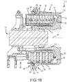
FIG. 1B illustrates a brake assembly for mounting on an axle comprising a laminated dimpled foil metallic heat shield, in accordance with various embodiments; -
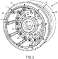
FIG. 2 illustrates a wheel having a laminated dimpled foil metallic heat shield, in accordance with various embodiments; -
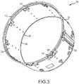
FIG. 3 illustrates a laminated dimpled foil metallic heat shield, in accordance with various embodiments; -
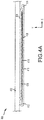
FIG. 4A illustrates a section through a laminated dimpled foil metallic heat shield, in accordance with various embodiments; -
FIG. 4B illustrates a section through a laminated dimpled foil metallic heat shield, in accordance with various embodiments; and -
FIG. 5 illustrates a method of manufacturing a foil laminated dimpled metallic heat shield, in accordance with various embodiments. - The detailed description of exemplary embodiments herein makes reference to the accompanying drawings, which show exemplary embodiments by way of illustration and their best mode. While these exemplary embodiments are described in sufficient detail to enable those skilled in the art to practice the disclosures, it should be understood that other embodiments may be realized and that logical, chemical, and mechanical changes may be made without departing from the spirit and scope of the disclosures. Thus, the detailed description herein is presented for purposes of illustration only and not of limitation. For example, the steps recited in any of the method or process descriptions may be executed in any order and are not necessarily limited to the order presented. Furthermore, any reference to singular includes plural embodiments, and any reference to more than one component or step may include a singular embodiment or step. Also, any reference to attached, fixed, connected or the like may include permanent, removable, temporary, partial, full and/or any other possible attachment option. Additionally, any reference to without contact (or similar phrases) may also include reduced contact or minimal contact.
- Referring now to
FIG. 1A , in accordance with various embodiments, anaircraft 10 includes landing gear, such as a leftmain landing gear 12, a rightmain landing gear 14, andnose landing gear 16. The leftmain landing gear 12, rightmain landing gear 14, andnose landing gear 16 typically support theaircraft 10 when theaircraft 10 is not flying, thereby allowing theaircraft 10 to taxi, take off, and land without damage. In various embodiments, the leftmain landing gear 12 includes afirst wheel 13A and asecond wheel 13B coupled by anaxle 20. In various embodiments, the rightmain landing gear 14 includes afirst wheel 15A and asecond wheel 15B coupled by anaxle 22. In various embodiments, thenose landing gear 16 includes afirst nose wheel 17A and a second nose wheel 17B coupled by anaxle 24. In various embodiments, theaircraft 10 comprises any number of landing gear(s), and each landing gear comprises any number of wheels. In various embodiments, the leftmain landing gear 12, rightmain landing gear 14, andnose landing gear 16 are retracted when theaircraft 10 is in flight. In various embodiments, one or more of the leftmain landing gear 12, rightmain landing gear 14, andnose landing gear 16 extends from an underside of afuselage 28 of theaircraft 10, or from an underside of thewings 30 thereof. - In various embodiments, the
aircraft 10 also includes a brake system that is applied to one or more of thewheels main landing gear 12, rightmain landing gear 14, and/ornose landing gear 16. Such brake systems of theaircraft 10 typically comprise a collection of assemblies, subsystems, and/or units that produce output signals for controlling the braking force and/or torque applied at one or more of thewheels main landing gear 12, rightmain landing gear 14, and/ornose landing gear 16, and each brake is typically mounted to eachwheel aircraft 10 further include a non-rotatable wheel support, thewheels - Referring now to
FIG. 1B , a brake assembly for mounting on anaxle 110 comprising a laminated dimpled foilmetallic heat shield 140 is located on theaircraft 10 ofFIG. 1-A , in accordance with various embodiments. The brake assembly for mounting on anaxle 110 typically comprises abogie axle 112, a wheel 114 (e.g., thewheels FIG. 1-A ) including ahub 116 and wheel well 118, aweb 120, a torque take-outassembly 122, one ormore torque bars 124, a wheelrotational axis 126, awheel well recess 128, anactuator 130,multiple brake rotors 32,multiple brake stators 34, apressure plate 36, anend plate 38, a laminated dimpled foilmetallic heat shield 140 which may havesections 142, multipleheat shield carriers 144, anair gap 146, multipletorque bar bolts 148, atorque bar pin 151, awheel web hole 152, multipleheat shield fasteners 153, multiple rotor lugs 154, andmultiple stator slots 156. - Brake disks (e.g., the interleaved
brake rotors 32 and brake stators 34) are disposed in thewheel well recess 128 of thewheel well 118. Thebrake rotors 32 are typically secured to the torque bars 124 for rotating with thewheel 114, while thebrake stators 34 are typically engaged with the torque take-outassembly 122. At least oneactuator 130 is typically operable to compress the interleavedbrake rotors 32 andbrake stators 34 for stopping theaircraft 10 ofFIG. 1A . In the embodiment ofFIG. 1B , theactuator 130 is shown as a hydraulically actuated piston. Thepressure plate 36 andend plate 38 are disposed at opposite ends of the interleavedbrake rotors 32 andbrake stators 34. - Through compression of the
brake rotors 32 andbrake stators 34 between thepressure plate 36 andend plate 38, the resulting frictional contact slows, stops, and/or prevents rotation of thewheel 114. The torque take-outassembly 122 is typically secured to a stationary portion of a landing gear truck, such as a bogie beam or other landing gear strut, such that the torque take-outassembly 122 andbrake stators 34 are prevented from rotating during braking of theaircraft 10 ofFIG. 1A . Thebrake rotors 32 andbrake stators 34 are typically fabricated from various materials, such as, for example carbon materials. The brake disks typically withstand and dissipate the heat generated from contact between the brake disks while braking theaircraft 10 ofFIG. 1A . - According to various embodiments and with reference to
FIGS. 1 and2 , awheel 200 having a laminated dimpled foil metallic heat shield is provided.Wheel 200 comprises anoutboard lip 202, coupled to awheel disk 208 bywheel tie bolts 212, and aninboard lip 204 defining arim 206 about thewheel disk 208. Ahub 210 is centered throughwheel disk 208 and may comprisebearings 214. Therim 206 extends axially with respect to thehub 210 about the circumference ofwheel disk 208. A laminated dimpled foilmetallic heat shield 216 lies radially inward ofrim 206 betweeninboard lip 204 andwheel disk 208 ofwheel 200. Laminated dimpled foilmetallic heat shield 216 comprises a cylindrical structure extending circumferentially about the axis ofhub 210 around the inner diameter ofrim 206. In various embodiments, laminated dimpled foilmetallic heat shield 216 may be coupledproximate rim 206 byfasteners 218 and may be heldproximate rim 206, withchin ring 220 proximateinboard lip 204, by an interference between laminated dimpled foilmetallic heat shield 216 andtorque bar 222. In various embodiments,torque bar 222 may be coupled towheel disk 208 at an outboard end and may be coupled to laminated dimpled foilmetallic heat shield 216 at an inboard endproximate chin ring 220 byfasteners 218. - With reference now to
FIG. 3 , in various embodiments, a laminated dimpled foilmetallic heat shield 300 is provided. Laminated dimpled foilmetallic heat shield 300 comprisesouter diameter 301,outboard edge 302,inner diameter 303, andinboard edge 304. Achin ring 312 is coupled aboutinboard edge 304. In various embodiments,torque bar spacers 308 comprising first mounting features 310 extend radially through theinner diameter 303 andouter diameter 301. In various embodiments, a plurality oftorque bar spacers 308 corresponding to a plurality of torque bars such as torque bars 222 may be arrayed circumferentially aboutinboard edge 304proximate chin ring 312. In various embodiments, atorque bar spacer 308 may provide a single point of contact and a standoff distance between laminated dimpled foilmetallic heat shield 300 and a torque bar such astorque bar 222 and, in that regard, a torque bar spacer may tend to limit conductive heat transfer between the torque bar and the laminated dimpled foil metallic heat shield. In various embodiments, thefirst mounting feature 310 may couple laminated dimpled foilmetallic heat shield 300 to a rim such asrim 206 and may interface with a rim proximate an inboard lip such asinboard lip 204. In various embodiments,torque bar spacers 308 may comprise asecond mounting feature 314 which provides a coupling interface betweenchin ring 312 andinboard edge 304. In various embodiments,studs 306 may be coupled to and extend a distance radially outward ofouter diameter 301 to provide a standoff distance between laminated dimpled foilmetallic heat shield 300 and a rim such asrim 206. - In various embodiments, the thickness of a laminated dimpled foil metallic heat shield may be between 0.127 mm [0.005 inches] and 38.1 mm [1.5 inches], or between 1.27 mm [0.05 inch] and 25.4 mm [1.0 inches], or between 2.54 mm [0.1 inches] and 12.7 mm [0.5 inches]. In various embodiments, the length of a laminated dimpled foil metallic heat shield may be defined by the axial length of a wheel, such as between an inboard lip and a wheel disk. In various embodiments a laminated dimpled foil metallic heat shield may be made of steel, stainless steel, titanium, titanium alloy, aluminum, aluminum alloy, or may be a surface treated metal or metal alloy.
- In various embodiments and with reference now to
FIG. 4A , a laminated dimpled foilmetallic heat shield 400 comprises various features, materials, geometries, construction, manufacturing techniques, and/or internal components similar to laminated dimpled foilmetallic heat shield 300 and is shown comprising alternating metallic and foil layers extending radially inward (along the Y-axis) from the inner diameter of heatsensitive structure 402 and axially (along the X-axis) and extends circumferentially about an inner diameter of heatsensitive structure 402. A firstmetallic layer 404 is coupled to a firstdimpled foil layer 406 and to the inner diameter of heatsensitive structure 402. Secondmetallic layer 408 is coupled firstdimpled foil layer 406. In various embodiments, the edges of firstmetallic layer 404 and secondmetallic layer 408 may extend (along the X-axis) a distance beyond the firstdimpled foil layer 406 and be joined, such as by welding 414, or by crimping 412. In this regard, firstdimpled foil layer 406 may tend to be sandwiched between firstmetallic layer 404 and secondmetallic layer 408. In various embodiments, one or more metallic layers, such as firstmetallic layer 404 and secondmetallic layer 408, may be surface treated to increase thermal reflectivity or hardness. - In various embodiments and with reference now to
FIG. 4B , a laminated dimpled foilmetallic heat shield 401 is shown comprising features, materials, geometries, components, and manufacturing techniques similar to lamented dimpled foilmetallic heat shield 400. Laminated dimpled foilmetallic heat shield 401 comprises alternating metallic and foil layers extending radially inward (along the Y-axis) from the inner diameter of heatsensitive structure 402 and axially (along the X-axis) and extends circumferentially about the inner diameter of heatsensitive structure 402. A firstmetallic layer 404 is coupled to a firstdimpled foil layer 406 and to the inner diameter of heatsensitive structure 402. A seconddimpled foil layer 410 is coupled radially inward of the first dimpled foil layer. Secondmetallic layer 408 is coupled radially inward of the seconddimpled foil layer 410, tending to sandwich first dimpledfoil layer 406 and seconddimpled foil layer 410 between firstmetallic layer 404 and secondmetallic layer 408. - In various embodiments, a dimpled foil layer such as first
dimpled foil layer 406 and seconddimpled foil layer 410 may comprise a plane of metallic material having a plurality of dimples (416) raised at least one of above or below the plane of metallic material. In this regard, the plane of a dimpled foil layer may be suspended between a first metallic layer, such as firstmetallic layer 404, and a second metallic layer, such as secondmetallic layer 408, with the points of contact between the dimpled foil layer and the metallic layers (such as 404, 408) being at a surface (418) of a dimple. In this regard, a dimpled foil layer may tend to reduce conductive heat transfer between the metallic layers, may tend to reduce convective heat transfer by tending to segregate air spaces between the metallic layers, and may tend to reduce radiative heat transfer between the metallic layers. In this regard, a laminated dimpled foil metallic heat shield may tend to reduce radiative transfer of heat to from brake rotor or a brake stator (e.g., 32, 34, 36, and 38 ofFIG. 1 ) to a heat sensitive structure. In various embodiments, the dimples of two or more dimpled foil layers may be configured to inhibit nesting or stacking of dimples which may tend to increase a contact area between the dimpled foil layers or tend to allow contact between the planes of the dimpled foil layers. In various embodiments a plurality of dimples may define about a 25.4 mm (1 in) ± 12.7 mm (0.5 in) grid between dimples. In various embodiments the diameter of each of the plurality of dimples may be 5.08 mm (0.2 in) ± 3.81 mm (0.15 in). - In various embodiments and with reference now to
FIG. 5 , amethod 500 of manufacturing a laminated dimpled foil metallic heat shield may comprise shaping a first metallic layer, a second metallic layer, and a first dimpled foil layer into a cylindrical structure (step 502) having the first dimpled foil layer between the first metallic layer and the second metallic layer; coupling the first metallic layer and the second metallic layer (step 504) at the edges of the first metallic layer and the second metallic layer such as, for example, by welding or crimping. In various embodiments, the method may further comprise disposing a second dimpled foil layer between the first metallic layer and the second metallic layer (step 506).In various embodiments, the laminated dimpled foil metallic heat shield may be coupled at an inner diameter of a heat sensitive structure. - Benefits, other advantages, and solutions to problems have been described herein with regard to specific embodiments. Furthermore, the connecting lines shown in the various figures contained herein are intended to represent exemplary functional relationships and/or physical couplings between the various elements. It should be noted that many alternative or additional functional relationships or physical connections may be present in a practical system. However, the benefits, advantages, solutions to problems, and any elements that may cause any benefit, advantage, or solution to occur or become more pronounced are not to be construed as critical, required, or essential features or elements of the disclosures.
- The scope of the disclosures is accordingly to be limited by nothing other than the appended claims, in which reference to an element in the singular is not intended to mean "one and only one" unless explicitly so stated, but rather "one or more." Moreover, where a phrase similar to "at least one of A, B, or C" is used in the claims, it is intended that the phrase be interpreted to mean that A alone may be present in an embodiment, B alone may be present in an embodiment, C alone may be present in an embodiment, or that any combination of the elements A, B and C may be present in a single embodiment; for example, A and B, A and C, B and C, or A and B and C. Different cross-hatching is used throughout the figures to denote different parts but not necessarily to denote the same or different materials.
- Systems, methods and apparatus are provided herein. In the detailed description herein, references to "one embodiment", "an embodiment", "an example embodiment", etc., indicate that the embodiment described may include a particular feature, structure, or characteristic, but every embodiment may not necessarily include the particular feature, structure, or characteristic. Moreover, such phrases are not necessarily referring to the same embodiment. Further, when a particular feature, structure, or characteristic is described in connection with an embodiment, it is submitted that it is within the knowledge of one skilled in the art to affect such feature, structure, or characteristic in connection with other embodiments whether or not explicitly described. After reading the description, it will be apparent to one skilled in the relevant art(s) how to implement the disclosure in alternative embodiment
- Furthermore, no element, component, or method step in the present disclosure is intended to be dedicated to the public regardless of whether the element, component, or method step is explicitly recited in the claims. As used herein, the terms "comprises", "comprising", or any other variation thereof, are intended to cover a non-exclusive inclusion, such that a process, method, article, or apparatus that comprises a list of elements does not include only those elements but may include other elements not expressly listed or inherent to such process, method, article, or apparatus.
Claims (14)
- A laminated dimpled foil metallic heat shield (300) assembly having a cylindrical structure with an outer diameter (301) and an inner diameter (303), comprising:a first metallic layer (404) defining the outer diameter (301), an inboard edge (304) and an outboard edge (302) of the laminated dimpled foil metallic heat shield assembly;a second metallic layer (408) defining the inner diameter (303) of the laminated dimpled foil metallic heat shield assembly; anda first dimpled foil layer (406) extending about a first circumference between the inner diameter (303) and the outer diameter (301).
- The laminated dimpled foil metallic heat shield of claim 1, wherein the first dimpled foil layer (404) comprises a plane of metallic material having a plurality of dimples raised at least one of above or below the plane of metallic material.
- The laminated dimpled foil metallic heat shield of claim 2, further comprising a second dimpled foil layer (410) extending about a second circumference between the inner diameter (303) and the outer diameter (301).
- The laminated dimpled foil metallic heat shield of any preceding claim, wherein the first metallic layer (404) and the second metallic layer (408) are joined about the inboard edge (304) and about the outboard edge (302).
- The laminated dimpled foil metallic heat shield of any preceding claim, further comprising a torque bar spacer (308) extending radially through the inner diameter (303) and the outer diameter (301).
- The laminated dimpled foil metallic heat shield of claim 5, further comprising a chin ring (312) coupled at the inboard edge (304).
- The laminated dimpled foil metallic heat shield assembly of claim 6, further comprising a stud (306) extending radially outward from the first metallic layer (404).
- The laminated dimpled foil metallic heat shield of claim 6, wherein the torque bar spacer (308) comprises a first mounting feature (310) and a second mounting feature (314), wherein the first mounting feature (310) is configured to interface the laminated dimpled foil metallic heat shield to a rim (206)) of a wheel, wherein the second mounting feature (314) provides a coupling interface between the chin ring (312) and the inboard edge (304).
- The laminated dimpled foil metallic heat shield assembly of claim 8, wherein the torque bar spacer (308) is configured to provide a first standoff distance between the rim (206) of the wheel and the outer diameter (301) of the laminated dimpled foil metallic heat shield and configured to provide a second standoff distance between the inner diameter (303) of the laminated dimpled foil metallic heat shield assembly and a torque bar (222) coupled to the torque bar spacer (308).
- The laminated dimpled foil metallic heat shield of claim 1, further comprising at least one of steel, stainless steel, titanium, titanium alloy, aluminum, or aluminum alloy.
- A brake assembly for mounting on an axle (110) comprising:a brake rotor;a wheel (114) comprising a wheel disk (208) coupled and a hub (116), and having an outboard lip (202) and an inboard lip (204) defining a rim (206) about the wheel disk (208) extending axially with respect to the hub (206); anda laminated dimpled foil metallic heat shield assembly as required by any preceding claim.
- The brake assembly of claim 11, wherein the laminated dimpled foil metallic heat shield extends along an axis of the hub (206) between the wheel disk (208) and the inboard lip (204), wherein the first metallic layer (404) is proximate the rim (206) and the second metallic layer (408) is proximate the brake rotor.
- The brake assembly of claim 11 when dependent on claim 9, wherein the torque bar is coupled to the torque bar spacer (308) at a first end of the torque bar (222) proximate the outboard lip, and wherein the torque bar (222) is coupled to the wheel disk (218) at a second end of the torque bar (222), wherein the torque bar (222) is coupled to the brake rotor.
- A method of manufacturing a laminated dimpled foil metallic heat shield, the method comprising:shaping a first metallic layer, a second metallic layer, and a first dimpled foil layer into a cylindrical structure having the first dimpled foil layer between the first metallic layer and the second metallic layer; andcoupling the first metallic layer and the second metallic layer at an edge of the first metallic layer and the second metallic layer.
Applications Claiming Priority (1)
| Application Number | Priority Date | Filing Date | Title |
|---|---|---|---|
| US15/887,590 US10967961B2 (en) | 2018-02-02 | 2018-02-02 | Laminated dimpled foil metallic heat shield |
Publications (2)
| Publication Number | Publication Date |
|---|---|
| EP3521161A1 true EP3521161A1 (en) | 2019-08-07 |
| EP3521161B1 EP3521161B1 (en) | 2021-10-20 |
Family
ID=65268773
Family Applications (1)
| Application Number | Title | Priority Date | Filing Date |
|---|---|---|---|
| EP19154439.4A Active EP3521161B1 (en) | 2018-02-02 | 2019-01-30 | Laminated dimpled foil metallic heat shield |
Country Status (2)
| Country | Link |
|---|---|
| US (1) | US10967961B2 (en) |
| EP (1) | EP3521161B1 (en) |
Cited By (3)
| Publication number | Priority date | Publication date | Assignee | Title |
|---|---|---|---|---|
| EP3922481A1 (en) * | 2020-06-09 | 2021-12-15 | Goodrich Corporation | High thermal conductivity heat shield |
| EP4286180A1 (en) * | 2022-05-31 | 2023-12-06 | Goodrich Corporation | Heat shield retainers and heat shield bumper placement |
| US12415381B2 (en) | 2022-06-22 | 2025-09-16 | Goodrich Corporation | Heat shield retainers and bumper standoffs for heat shield retainers |
Families Citing this family (6)
| Publication number | Priority date | Publication date | Assignee | Title |
|---|---|---|---|---|
| GB2524097A (en) * | 2014-03-14 | 2015-09-16 | Airbus Operations Ltd | Wheel and gear assembly |
| US11572159B2 (en) * | 2018-10-29 | 2023-02-07 | Goodrich Corporation | Segmented heat shield with reduced interlayer thermal conduction |
| USD953940S1 (en) * | 2020-02-03 | 2022-06-07 | Paccar Inc | Heat shield |
| US12441084B2 (en) | 2021-10-20 | 2025-10-14 | Unison Industries, Llc | Thermal insulation system |
| US12305726B2 (en) * | 2022-06-06 | 2025-05-20 | Goodrich Corporation | Multi-layer aircraft brake insulator |
| EP4321769B1 (en) * | 2022-08-12 | 2026-02-18 | Goodrich Corporation | Heat shield panel |
Citations (4)
| Publication number | Priority date | Publication date | Assignee | Title |
|---|---|---|---|---|
| US5002342A (en) * | 1989-12-28 | 1991-03-26 | Aircraft Braking Systems Corporation | Brake assembly heat shield |
| US5958603A (en) * | 1997-06-09 | 1999-09-28 | Atd Corporation | Shaped multilayer metal foil shield structures and method of making |
| EP1304240A1 (en) * | 2001-10-10 | 2003-04-23 | Goodrich Corporation | Heat shield assembly for aircraft wheel and brake assembly |
| EP3159571A2 (en) * | 2015-10-20 | 2017-04-26 | Goodrich Corporation | Ventilated key-slot full circle heat shield |
Family Cites Families (7)
| Publication number | Priority date | Publication date | Assignee | Title |
|---|---|---|---|---|
| US3151712A (en) * | 1960-11-30 | 1964-10-06 | Budd Co | Insulating structure |
| US4703159A (en) * | 1980-07-02 | 1987-10-27 | The United States Of America As Represented By The Administrator Of The National Aeronautics And Space Administration | Method of manufacturing lightweight thermo-barrier material |
| DE3741733A1 (en) | 1987-12-09 | 1989-06-29 | Messerschmitt Boelkow Blohm | HIGH TEMPERATURE HEAT PROTECTION SYSTEM |
| US5199536A (en) * | 1992-02-13 | 1993-04-06 | The B. F. Goodrich Company | Heatshield installation for aircraft brake |
| US5851056A (en) | 1996-06-03 | 1998-12-22 | The B. F. Goodrich Company | Aircraft brake heat shield having easily removed heat shield sections |
| US6419056B1 (en) * | 1998-10-29 | 2002-07-16 | Aircraft Braking Systems Corp. | Apparatus for aircraft brake thermal management |
| US10077818B2 (en) * | 2016-06-17 | 2018-09-18 | Goodrich Corporation | Scalloped aircraft wheel rotor drive bar attachment boss for reduced thermal conduction |
-
2018
- 2018-02-02 US US15/887,590 patent/US10967961B2/en active Active
-
2019
- 2019-01-30 EP EP19154439.4A patent/EP3521161B1/en active Active
Patent Citations (4)
| Publication number | Priority date | Publication date | Assignee | Title |
|---|---|---|---|---|
| US5002342A (en) * | 1989-12-28 | 1991-03-26 | Aircraft Braking Systems Corporation | Brake assembly heat shield |
| US5958603A (en) * | 1997-06-09 | 1999-09-28 | Atd Corporation | Shaped multilayer metal foil shield structures and method of making |
| EP1304240A1 (en) * | 2001-10-10 | 2003-04-23 | Goodrich Corporation | Heat shield assembly for aircraft wheel and brake assembly |
| EP3159571A2 (en) * | 2015-10-20 | 2017-04-26 | Goodrich Corporation | Ventilated key-slot full circle heat shield |
Cited By (7)
| Publication number | Priority date | Publication date | Assignee | Title |
|---|---|---|---|---|
| EP3922481A1 (en) * | 2020-06-09 | 2021-12-15 | Goodrich Corporation | High thermal conductivity heat shield |
| EP4234269A1 (en) * | 2020-06-09 | 2023-08-30 | Goodrich Corporation | High thermal conductivity heat shield |
| US11802603B2 (en) | 2020-06-09 | 2023-10-31 | Goodrich Corporation | High thermal conductivity heat shield |
| EP4338977A1 (en) * | 2020-06-09 | 2024-03-20 | Goodrich Corporation | High thermal conductivity heat shield |
| EP4286180A1 (en) * | 2022-05-31 | 2023-12-06 | Goodrich Corporation | Heat shield retainers and heat shield bumper placement |
| US12515476B2 (en) | 2022-05-31 | 2026-01-06 | Goodrich Corporation | Heat shield retainers and heat shield bumper placement |
| US12415381B2 (en) | 2022-06-22 | 2025-09-16 | Goodrich Corporation | Heat shield retainers and bumper standoffs for heat shield retainers |
Also Published As
| Publication number | Publication date |
|---|---|
| US20190241257A1 (en) | 2019-08-08 |
| US10967961B2 (en) | 2021-04-06 |
| EP3521161B1 (en) | 2021-10-20 |
Similar Documents
| Publication | Publication Date | Title |
|---|---|---|
| EP3521161B1 (en) | Laminated dimpled foil metallic heat shield | |
| EP3480072B1 (en) | Shield attachment device | |
| EP3670955B1 (en) | Heat shield retainer and method | |
| US11572159B2 (en) | Segmented heat shield with reduced interlayer thermal conduction | |
| EP3767125B1 (en) | Heat shield retainer and methods | |
| EP3524517B1 (en) | Insulated torque plate foot assembly | |
| EP3734104A1 (en) | Hydraulic brake actuator piston adjuster assembly | |
| EP3726087B1 (en) | Multiple layer piston insulator for hydraulic brake actuator | |
| EP4283154B1 (en) | Stator clip for brake assembly | |
| US10309468B2 (en) | Torque plate barrel having blended barrel support pedestal | |
| EP3404283A1 (en) | Extended torque tube | |
| EP3539834B1 (en) | Aircraft brake heat shield | |
| EP3925874A1 (en) | Aircraft wheel torque bar spacer | |
| EP4414581B1 (en) | Use of profiled reaction face in hybrid torque bar applications | |
| EP3441637A1 (en) | Differential torque plate barrel thickness | |
| EP4289689B1 (en) | Multi-layer aircraft brake insulator | |
| EP4321768B1 (en) | Tapered torque plate barrel for improving dynamic stability | |
| US12331801B2 (en) | Stator clip for brake assembly | |
| EP3978776B1 (en) | Carbon brake stack assembly for improved life |
Legal Events
| Date | Code | Title | Description |
|---|---|---|---|
| PUAI | Public reference made under article 153(3) epc to a published international application that has entered the european phase |
Free format text: ORIGINAL CODE: 0009012 |
|
| STAA | Information on the status of an ep patent application or granted ep patent |
Free format text: STATUS: THE APPLICATION HAS BEEN PUBLISHED |
|
| AK | Designated contracting states |
Kind code of ref document: A1 Designated state(s): AL AT BE BG CH CY CZ DE DK EE ES FI FR GB GR HR HU IE IS IT LI LT LU LV MC MK MT NL NO PL PT RO RS SE SI SK SM TR |
|
| AX | Request for extension of the european patent |
Extension state: BA ME |
|
| STAA | Information on the status of an ep patent application or granted ep patent |
Free format text: STATUS: REQUEST FOR EXAMINATION WAS MADE |
|
| 17P | Request for examination filed |
Effective date: 20191126 |
|
| RBV | Designated contracting states (corrected) |
Designated state(s): AL AT BE BG CH CY CZ DE DK EE ES FI FR GB GR HR HU IE IS IT LI LT LU LV MC MK MT NL NO PL PT RO RS SE SI SK SM TR |
|
| STAA | Information on the status of an ep patent application or granted ep patent |
Free format text: STATUS: EXAMINATION IS IN PROGRESS |
|
| 17Q | First examination report despatched |
Effective date: 20201222 |
|
| GRAP | Despatch of communication of intention to grant a patent |
Free format text: ORIGINAL CODE: EPIDOSNIGR1 |
|
| STAA | Information on the status of an ep patent application or granted ep patent |
Free format text: STATUS: GRANT OF PATENT IS INTENDED |
|
| INTG | Intention to grant announced |
Effective date: 20210519 |
|
| GRAS | Grant fee paid |
Free format text: ORIGINAL CODE: EPIDOSNIGR3 |
|
| GRAA | (expected) grant |
Free format text: ORIGINAL CODE: 0009210 |
|
| STAA | Information on the status of an ep patent application or granted ep patent |
Free format text: STATUS: THE PATENT HAS BEEN GRANTED |
|
| AK | Designated contracting states |
Kind code of ref document: B1 Designated state(s): AL AT BE BG CH CY CZ DE DK EE ES FI FR GB GR HR HU IE IS IT LI LT LU LV MC MK MT NL NO PL PT RO RS SE SI SK SM TR |
|
| REG | Reference to a national code |
Ref country code: GB Ref legal event code: FG4D |
|
| REG | Reference to a national code |
Ref country code: CH Ref legal event code: EP |
|
| REG | Reference to a national code |
Ref country code: IE Ref legal event code: FG4D |
|
| REG | Reference to a national code |
Ref country code: DE Ref legal event code: R096 Ref document number: 602019008394 Country of ref document: DE |
|
| REG | Reference to a national code |
Ref country code: AT Ref legal event code: REF Ref document number: 1439738 Country of ref document: AT Kind code of ref document: T Effective date: 20211115 |
|
| REG | Reference to a national code |
Ref country code: LT Ref legal event code: MG9D |
|
| REG | Reference to a national code |
Ref country code: NL Ref legal event code: MP Effective date: 20211020 |
|
| REG | Reference to a national code |
Ref country code: AT Ref legal event code: MK05 Ref document number: 1439738 Country of ref document: AT Kind code of ref document: T Effective date: 20211020 |
|
| PG25 | Lapsed in a contracting state [announced via postgrant information from national office to epo] |
Ref country code: RS Free format text: LAPSE BECAUSE OF FAILURE TO SUBMIT A TRANSLATION OF THE DESCRIPTION OR TO PAY THE FEE WITHIN THE PRESCRIBED TIME-LIMIT Effective date: 20211020 Ref country code: LT Free format text: LAPSE BECAUSE OF FAILURE TO SUBMIT A TRANSLATION OF THE DESCRIPTION OR TO PAY THE FEE WITHIN THE PRESCRIBED TIME-LIMIT Effective date: 20211020 Ref country code: FI Free format text: LAPSE BECAUSE OF FAILURE TO SUBMIT A TRANSLATION OF THE DESCRIPTION OR TO PAY THE FEE WITHIN THE PRESCRIBED TIME-LIMIT Effective date: 20211020 Ref country code: BG Free format text: LAPSE BECAUSE OF FAILURE TO SUBMIT A TRANSLATION OF THE DESCRIPTION OR TO PAY THE FEE WITHIN THE PRESCRIBED TIME-LIMIT Effective date: 20220120 Ref country code: AT Free format text: LAPSE BECAUSE OF FAILURE TO SUBMIT A TRANSLATION OF THE DESCRIPTION OR TO PAY THE FEE WITHIN THE PRESCRIBED TIME-LIMIT Effective date: 20211020 |
|
| PG25 | Lapsed in a contracting state [announced via postgrant information from national office to epo] |
Ref country code: IS Free format text: LAPSE BECAUSE OF FAILURE TO SUBMIT A TRANSLATION OF THE DESCRIPTION OR TO PAY THE FEE WITHIN THE PRESCRIBED TIME-LIMIT Effective date: 20220220 Ref country code: SE Free format text: LAPSE BECAUSE OF FAILURE TO SUBMIT A TRANSLATION OF THE DESCRIPTION OR TO PAY THE FEE WITHIN THE PRESCRIBED TIME-LIMIT Effective date: 20211020 Ref country code: PT Free format text: LAPSE BECAUSE OF FAILURE TO SUBMIT A TRANSLATION OF THE DESCRIPTION OR TO PAY THE FEE WITHIN THE PRESCRIBED TIME-LIMIT Effective date: 20220221 Ref country code: PL Free format text: LAPSE BECAUSE OF FAILURE TO SUBMIT A TRANSLATION OF THE DESCRIPTION OR TO PAY THE FEE WITHIN THE PRESCRIBED TIME-LIMIT Effective date: 20211020 Ref country code: NO Free format text: LAPSE BECAUSE OF FAILURE TO SUBMIT A TRANSLATION OF THE DESCRIPTION OR TO PAY THE FEE WITHIN THE PRESCRIBED TIME-LIMIT Effective date: 20220120 Ref country code: NL Free format text: LAPSE BECAUSE OF FAILURE TO SUBMIT A TRANSLATION OF THE DESCRIPTION OR TO PAY THE FEE WITHIN THE PRESCRIBED TIME-LIMIT Effective date: 20211020 Ref country code: LV Free format text: LAPSE BECAUSE OF FAILURE TO SUBMIT A TRANSLATION OF THE DESCRIPTION OR TO PAY THE FEE WITHIN THE PRESCRIBED TIME-LIMIT Effective date: 20211020 Ref country code: HR Free format text: LAPSE BECAUSE OF FAILURE TO SUBMIT A TRANSLATION OF THE DESCRIPTION OR TO PAY THE FEE WITHIN THE PRESCRIBED TIME-LIMIT Effective date: 20211020 Ref country code: GR Free format text: LAPSE BECAUSE OF FAILURE TO SUBMIT A TRANSLATION OF THE DESCRIPTION OR TO PAY THE FEE WITHIN THE PRESCRIBED TIME-LIMIT Effective date: 20220121 Ref country code: ES Free format text: LAPSE BECAUSE OF FAILURE TO SUBMIT A TRANSLATION OF THE DESCRIPTION OR TO PAY THE FEE WITHIN THE PRESCRIBED TIME-LIMIT Effective date: 20211020 |
|
| REG | Reference to a national code |
Ref country code: DE Ref legal event code: R097 Ref document number: 602019008394 Country of ref document: DE |
|
| PG25 | Lapsed in a contracting state [announced via postgrant information from national office to epo] |
Ref country code: SM Free format text: LAPSE BECAUSE OF FAILURE TO SUBMIT A TRANSLATION OF THE DESCRIPTION OR TO PAY THE FEE WITHIN THE PRESCRIBED TIME-LIMIT Effective date: 20211020 Ref country code: SK Free format text: LAPSE BECAUSE OF FAILURE TO SUBMIT A TRANSLATION OF THE DESCRIPTION OR TO PAY THE FEE WITHIN THE PRESCRIBED TIME-LIMIT Effective date: 20211020 Ref country code: RO Free format text: LAPSE BECAUSE OF FAILURE TO SUBMIT A TRANSLATION OF THE DESCRIPTION OR TO PAY THE FEE WITHIN THE PRESCRIBED TIME-LIMIT Effective date: 20211020 Ref country code: EE Free format text: LAPSE BECAUSE OF FAILURE TO SUBMIT A TRANSLATION OF THE DESCRIPTION OR TO PAY THE FEE WITHIN THE PRESCRIBED TIME-LIMIT Effective date: 20211020 Ref country code: DK Free format text: LAPSE BECAUSE OF FAILURE TO SUBMIT A TRANSLATION OF THE DESCRIPTION OR TO PAY THE FEE WITHIN THE PRESCRIBED TIME-LIMIT Effective date: 20211020 Ref country code: CZ Free format text: LAPSE BECAUSE OF FAILURE TO SUBMIT A TRANSLATION OF THE DESCRIPTION OR TO PAY THE FEE WITHIN THE PRESCRIBED TIME-LIMIT Effective date: 20211020 |
|
| REG | Reference to a national code |
Ref country code: DE Ref legal event code: R119 Ref document number: 602019008394 Country of ref document: DE |
|
| PLBE | No opposition filed within time limit |
Free format text: ORIGINAL CODE: 0009261 |
|
| STAA | Information on the status of an ep patent application or granted ep patent |
Free format text: STATUS: NO OPPOSITION FILED WITHIN TIME LIMIT |
|
| PG25 | Lapsed in a contracting state [announced via postgrant information from national office to epo] |
Ref country code: MC Free format text: LAPSE BECAUSE OF FAILURE TO SUBMIT A TRANSLATION OF THE DESCRIPTION OR TO PAY THE FEE WITHIN THE PRESCRIBED TIME-LIMIT Effective date: 20211020 |
|
| REG | Reference to a national code |
Ref country code: CH Ref legal event code: PL |
|
| 26N | No opposition filed |
Effective date: 20220721 |
|
| REG | Reference to a national code |
Ref country code: BE Ref legal event code: MM Effective date: 20220131 |
|
| PG25 | Lapsed in a contracting state [announced via postgrant information from national office to epo] |
Ref country code: LU Free format text: LAPSE BECAUSE OF NON-PAYMENT OF DUE FEES Effective date: 20220130 Ref country code: DE Free format text: LAPSE BECAUSE OF NON-PAYMENT OF DUE FEES Effective date: 20220802 Ref country code: AL Free format text: LAPSE BECAUSE OF FAILURE TO SUBMIT A TRANSLATION OF THE DESCRIPTION OR TO PAY THE FEE WITHIN THE PRESCRIBED TIME-LIMIT Effective date: 20211020 |
|
| PG25 | Lapsed in a contracting state [announced via postgrant information from national office to epo] |
Ref country code: SI Free format text: LAPSE BECAUSE OF FAILURE TO SUBMIT A TRANSLATION OF THE DESCRIPTION OR TO PAY THE FEE WITHIN THE PRESCRIBED TIME-LIMIT Effective date: 20211020 Ref country code: BE Free format text: LAPSE BECAUSE OF NON-PAYMENT OF DUE FEES Effective date: 20220131 |
|
| PG25 | Lapsed in a contracting state [announced via postgrant information from national office to epo] |
Ref country code: LI Free format text: LAPSE BECAUSE OF NON-PAYMENT OF DUE FEES Effective date: 20220131 Ref country code: CH Free format text: LAPSE BECAUSE OF NON-PAYMENT OF DUE FEES Effective date: 20220131 |
|
| PG25 | Lapsed in a contracting state [announced via postgrant information from national office to epo] |
Ref country code: IE Free format text: LAPSE BECAUSE OF NON-PAYMENT OF DUE FEES Effective date: 20220130 |
|
| PG25 | Lapsed in a contracting state [announced via postgrant information from national office to epo] |
Ref country code: IT Free format text: LAPSE BECAUSE OF FAILURE TO SUBMIT A TRANSLATION OF THE DESCRIPTION OR TO PAY THE FEE WITHIN THE PRESCRIBED TIME-LIMIT Effective date: 20211020 |
|
| P01 | Opt-out of the competence of the unified patent court (upc) registered |
Effective date: 20230521 |
|
| PG25 | Lapsed in a contracting state [announced via postgrant information from national office to epo] |
Ref country code: MK Free format text: LAPSE BECAUSE OF FAILURE TO SUBMIT A TRANSLATION OF THE DESCRIPTION OR TO PAY THE FEE WITHIN THE PRESCRIBED TIME-LIMIT Effective date: 20211020 Ref country code: CY Free format text: LAPSE BECAUSE OF FAILURE TO SUBMIT A TRANSLATION OF THE DESCRIPTION OR TO PAY THE FEE WITHIN THE PRESCRIBED TIME-LIMIT Effective date: 20211020 |
|
| PG25 | Lapsed in a contracting state [announced via postgrant information from national office to epo] |
Ref country code: HU Free format text: LAPSE BECAUSE OF FAILURE TO SUBMIT A TRANSLATION OF THE DESCRIPTION OR TO PAY THE FEE WITHIN THE PRESCRIBED TIME-LIMIT; INVALID AB INITIO Effective date: 20190130 |
|
| PG25 | Lapsed in a contracting state [announced via postgrant information from national office to epo] |
Ref country code: MT Free format text: LAPSE BECAUSE OF FAILURE TO SUBMIT A TRANSLATION OF THE DESCRIPTION OR TO PAY THE FEE WITHIN THE PRESCRIBED TIME-LIMIT Effective date: 20211020 |
|
| PG25 | Lapsed in a contracting state [announced via postgrant information from national office to epo] |
Ref country code: TR Free format text: LAPSE BECAUSE OF FAILURE TO SUBMIT A TRANSLATION OF THE DESCRIPTION OR TO PAY THE FEE WITHIN THE PRESCRIBED TIME-LIMIT Effective date: 20211020 |
|
| PGFP | Annual fee paid to national office [announced via postgrant information from national office to epo] |
Ref country code: GB Payment date: 20251220 Year of fee payment: 8 |
|
| PGFP | Annual fee paid to national office [announced via postgrant information from national office to epo] |
Ref country code: FR Payment date: 20251217 Year of fee payment: 8 |