EP3521137A1 - Steering controller - Google Patents
Steering controller Download PDFInfo
- Publication number
- EP3521137A1 EP3521137A1 EP19154214.1A EP19154214A EP3521137A1 EP 3521137 A1 EP3521137 A1 EP 3521137A1 EP 19154214 A EP19154214 A EP 19154214A EP 3521137 A1 EP3521137 A1 EP 3521137A1
- Authority
- EP
- European Patent Office
- Prior art keywords
- steering
- steered
- angle
- target
- calculation circuit
- Prior art date
- Legal status (The legal status is an assumption and is not a legal conclusion. Google has not performed a legal analysis and makes no representation as to the accuracy of the status listed.)
- Granted
Links
Images




Classifications
-
- B—PERFORMING OPERATIONS; TRANSPORTING
- B62—LAND VEHICLES FOR TRAVELLING OTHERWISE THAN ON RAILS
- B62D—MOTOR VEHICLES; TRAILERS
- B62D6/00—Arrangements for automatically controlling steering depending on driving conditions sensed and responded to, e.g. control circuits
- B62D6/008—Control of feed-back to the steering input member, e.g. simulating road feel in steer-by-wire applications
-
- B—PERFORMING OPERATIONS; TRANSPORTING
- B62—LAND VEHICLES FOR TRAVELLING OTHERWISE THAN ON RAILS
- B62D—MOTOR VEHICLES; TRAILERS
- B62D5/00—Power-assisted or power-driven steering
- B62D5/04—Power-assisted or power-driven steering electrical, e.g. using an electric servo-motor connected to, or forming part of, the steering gear
- B62D5/0457—Power-assisted or power-driven steering electrical, e.g. using an electric servo-motor connected to, or forming part of, the steering gear characterised by control features of the drive means as such
- B62D5/046—Controlling the motor
- B62D5/0466—Controlling the motor for returning the steering wheel to neutral position
-
- B—PERFORMING OPERATIONS; TRANSPORTING
- B62—LAND VEHICLES FOR TRAVELLING OTHERWISE THAN ON RAILS
- B62D—MOTOR VEHICLES; TRAILERS
- B62D3/00—Steering gears
- B62D3/02—Steering gears mechanical
- B62D3/12—Steering gears mechanical of rack-and-pinion type
-
- B—PERFORMING OPERATIONS; TRANSPORTING
- B62—LAND VEHICLES FOR TRAVELLING OTHERWISE THAN ON RAILS
- B62D—MOTOR VEHICLES; TRAILERS
- B62D5/00—Power-assisted or power-driven steering
- B62D5/04—Power-assisted or power-driven steering electrical, e.g. using an electric servo-motor connected to, or forming part of, the steering gear
- B62D5/0457—Power-assisted or power-driven steering electrical, e.g. using an electric servo-motor connected to, or forming part of, the steering gear characterised by control features of the drive means as such
- B62D5/046—Controlling the motor
-
- B—PERFORMING OPERATIONS; TRANSPORTING
- B62—LAND VEHICLES FOR TRAVELLING OTHERWISE THAN ON RAILS
- B62D—MOTOR VEHICLES; TRAILERS
- B62D5/00—Power-assisted or power-driven steering
- B62D5/04—Power-assisted or power-driven steering electrical, e.g. using an electric servo-motor connected to, or forming part of, the steering gear
- B62D5/0457—Power-assisted or power-driven steering electrical, e.g. using an electric servo-motor connected to, or forming part of, the steering gear characterised by control features of the drive means as such
- B62D5/046—Controlling the motor
- B62D5/0463—Controlling the motor calculating assisting torque from the motor based on driver input
-
- B—PERFORMING OPERATIONS; TRANSPORTING
- B62—LAND VEHICLES FOR TRAVELLING OTHERWISE THAN ON RAILS
- B62D—MOTOR VEHICLES; TRAILERS
- B62D6/00—Arrangements for automatically controlling steering depending on driving conditions sensed and responded to, e.g. control circuits
- B62D6/002—Arrangements for automatically controlling steering depending on driving conditions sensed and responded to, e.g. control circuits computing target steering angles for front or rear wheels
Definitions
- the invention relates to steering controllers.
- a "steer-by-wire" steering system is known in the related art.
- a steering wheel is mechanically disconnected from steered wheel(s).
- Such a steering system includes a reaction motor and a steering motor.
- the reaction motor functions as a source of a steering reaction to be provided to a steering shaft.
- the steering motor functions as a source of a steering force to steer steered wheel(s).
- a controller for the steering system exercises not only reaction control to produce a steering reaction from the reaction motor but also steering control to steer the steered wheel(s) using the steering motor.
- Such a controller will hereinafter be referred to as a "steering controller”.
- JP 2014-151881 A discloses a steering controller that exercises steering control described below.
- the steering controller calculates a steady-state steering controlled variable and a differential steering controlled variable.
- the steady-state steering controlled variable is a controlled variable responsive to a steering angle.
- the differential steering controlled variable is a controlled variable responsive to a steering angular velocity.
- the steering controller adds up the steady-state steering controlled variable and the differential steering controlled variable and defines the resulting value as a target steered angle for steered wheel(s).
- the steering controller controls supply of power to a steering motor such that an actual steered angle corresponds to the target steered angle.
- the steering controller calculates the differential steering controlled variable in accordance with a vehicle travel mode selected from a plurality of modes including a normal mode and a sports mode. This enables the phase of the steered angle with respect to the steering angular velocity to be adaptable to the travel mode selected, making it possible to provide a target steering response.
- An object of the invention is to provide a steering controller that is able to effect proper steering of steered wheel(s).
- An aspect of the invention provides a steering controller to control a motor in accordance with a command value calculated in response to a steering state.
- the motor is a source of a driving force to be provided to a steering operation mechanism configured to steer a steered wheel of a vehicle.
- the steering controller includes a compensation control circuit to calculate a compensation amount in response to the steering state so as to compensate for at least one of an inertia component, a viscosity component, and a spring component of the steering operation mechanism in accordance with a target rotation angle of a rotator.
- the compensation amount is to be reflected in the command value.
- the rotator is configured to rotate in conjunction with steering of the steered wheel.
- the magnitude of influence of an inertia component, a viscosity component, and a spring component on steering of steered wheels may differ for each mechanism to steer the steered wheels. Differential steering control known in the related art may thus fail to reduce or eliminate the influence of an inertia component, a viscosity component, and a spring component on steering of steered wheels.
- the steering controller described above is configured such that the command value is reflective of the compensation amount for compensation of at least one of the inertia component, the viscosity component, and the spring component of the mechanism to steer the steered wheel.
- One example may involve compensating for only the inertia component when the inertia component significantly affects the steering of the steered wheel but the influence of the viscosity component and spring component is negligible.
- Another example may involve compensating for only the inertia component and the spring component when the inertia component and the spring component significantly affect the steering of the steered wheel but the influence of the viscosity component is negligible.
- Still another example may involve compensating for all of the inertia component, the viscosity component, and the spring component when all of the inertia component, the viscosity component, and the spring component affect the steering of the steered wheel.
- selectively compensating for the inertia component, the viscosity component, and the spring component in accordance with the characteristics of the mechanism to steer the steered wheel makes it possible to suitably reduce or eliminate any one, two, or all of the inertia component, the viscosity component, and the spring component that affect(s) the steering of the steered wheel.
- the steering controller controls the motor in accordance with the command value reflective of the compensation amount so as to effect proper steering of the steered wheel. This also provides proper steering response of the steered wheel.
- the steering controller may further include a first calculation circuit and a second calculation circuit.
- the first calculation circuit may be configured to calculate the target rotation angle of the rotator in accordance with the steering state.
- the second calculation circuit may be configured to calculate the command value by performing feedback control such that an actual rotation angle of the rotator corresponds to the target rotation angle.
- the compensation control circuit may include a compensation amount calculation circuit and an adder.
- the compensation amount calculation circuit may be configured to calculate the compensation amount in accordance with the target rotation angle calculated by the first calculation circuit.
- the adder may be configured to add the compensation amount to the target rotation angle so as to calculate a final target rotation angle to be used for the calculation of the command value.
- the compensation amount may be calculated by the compensation amount calculation circuit.
- the target rotation angle may be calculated by the first calculation circuit.
- the compensation amount calculated by the compensation amount calculation circuit is added to the target rotation angle calculated by the first calculation circuit. Consequently, the command value is reflective of the compensation amount.
- the motor of the steering controller may be a steering motor to provide a driving force to a steering operation shaft.
- the steering operation shaft is a component of the steering operation mechanism.
- a first embodiment of the invention involves using a steering controller in a steer-by-wire steering system.
- the steering controller is a controller 50.
- the steer-by-wire steering system is a steering system 10 for a vehicle.
- the vehicle steering system 10 includes a steering wheel 11 and a steering shaft 12 coupled to the steering wheel 11.
- the steering system 10 further includes a steering operation shaft 14 extending in a vehicle width direction.
- the vehicle width direction corresponds to the right-left direction in FIG. 1 .
- the ends of the steering operation shaft 14 are each coupled to an associated one of right and left steered wheels 16 through an associated one of tie rods 15.
- a rectilinear motion of the steering operation shaft 14 changes a steered angle ⁇ w of each steered wheel 16.
- the steering system 10 includes a reaction unit configured to produce a steering reaction.
- the reaction unit will be described below.
- the steering system 10 includes a reaction motor 31, a speed reducer 32, a rotation angle sensor 33, and a torque sensor 34 that are components of the reaction unit to produce a steering reaction.
- the term "steering reaction” refers to a force (or torque) exerted on the steering wheel 11 in a direction opposite to a direction in which the steering wheel 11 is turned by a driver. Providing the steering reaction to the steering wheel 11 enables the driver to feel a moderate resistance.
- the reaction motor 31 is a source of the steering reaction.
- Examples of the reaction motor 31 to be used include a brushless motor having three phases (e.g., U, V, and W phases).
- the reaction motor 31 (or to be more precise, the rotation shaft of the reaction motor 31) is coupled to the steering shaft 12 through the speed reducer 32.
- the speed reducer 32 is disposed on a portion of the steering shaft 12 located opposite to the steering wheel 11.
- a torque generated by the reaction motor 31 is provided to the steering shaft 12 in the form of the steering reaction.
- the rotation angle sensor 33 is disposed on the reaction motor 31.
- the rotation angle sensor 33 detects a rotation angle ⁇ a of the reaction motor 31.
- the rotation angle ⁇ a of the reaction motor 31 is used for calculation of a steering angle ⁇ s .
- the reaction motor 31 and the steering shaft 12 operate in conjunction with each other through the speed reducer 32.
- the rotation angle ⁇ a of the reaction motor 31 correlates with a rotation angle of the steering shaft 12 and also correlates with the steering angle ⁇ s that is a rotation angle of the steering wheel 11. This makes it possible to determine the steering angle ⁇ s in accordance with the rotation angle ⁇ a of the reaction motor 31.
- the torque sensor 34 detects a steering torque T h applied to the steering shaft 12 as a result of a turning operation performed on the steering wheel 11.
- the torque sensor 34 is disposed on a portion of the steering shaft 12 located closer to the steering wheel 11 relative to the speed reducer 32.
- the steering system 10 includes a steering unit configured to produce a steering force.
- the steering unit will be described below.
- the steering system 10 includes a steering motor 41, a speed reducer 42, and a rotation angle sensor 43 that are components of the steering unit to produce a steering force that is power to steer the steered wheels 16.
- the steering motor 41 is a source of the steering force.
- Examples of the steering motor 41 to be used include a three-phase brushless motor.
- the steering motor 41 (or to be more precise, the rotation shaft of the steering motor 41) is coupled to a pinion shaft 44 through the speed reducer 42.
- the pinion shaft 44 includes pinion teeth 44a.
- the steering operation shaft 14 includes rack teeth 14b.
- the pinion teeth 44a of the pinion shaft 44 are in mesh with the rack teeth 14b of the steering operation shaft 14.
- a torque generated by the steering motor 41 is provided to the steering operation shaft 14 through the pinion shaft 44.
- the torque generated by the steering motor 41 is provided in the form of the steering force.
- the steering operation shaft 14 moves in the vehicle width direction (i.e., the right-left direction in FIG. 1 ) in accordance with rotation of the steering motor 41.
- the rotation angle sensor 43 is disposed on the steering motor 41.
- the rotation angle sensor 43 detects a rotation angle ⁇ b of the steering motor 41.
- the steering system 10 includes a pinion shaft 13.
- the pinion shaft 13 is disposed to intersect with the steering operation shaft 14.
- the pinion shaft 13 includes pinion teeth 13a.
- the steering operation shaft 14 includes rack teeth 14a.
- the pinion teeth 13a of the pinion shaft 13 are in mesh with the rack teeth 14a of the steering operation shaft 14.
- the pinion shaft 13 is provided in order to support the steering operation shaft 14 inside a housing (not illustrated) together with the pinion shaft 44.
- the pinion shaft 13 functions as a support that supports the steering operation shaft 14 such that the steering operation shaft 14 is movable along its axis and pressed against the pinion shaft 13 and the pinion shaft 44. This supports the steering operation shaft 14 inside the housing.
- the support that supports the steering operation shaft 14 inside the housing may be a component other than the pinion shaft 13.
- the pinion shaft 44 and the steering operation shaft 14 are components of a steering operation mechanism to steer the steered wheels 16.
- the steering system 10 includes the controller 50.
- the controller 50 controls the reaction motor 31 and the steering motor 41 in accordance with detection results obtained by various sensors, such as the rotation angle sensor 33, the torque sensor 34, the rotation angle sensor 43, and a vehicle speed sensor 501.
- the vehicle speed sensor 501 is disposed on the vehicle.
- the vehicle speed sensor 501 detects a vehicle speed V that is a travel speed of the vehicle.
- the controller 50 exercises reaction control to produce a steering reaction responsive to the steering torque T h by controlling driving of the reaction motor 31.
- the controller 50 calculates a target steering reaction in accordance with the steering torque T h and the vehicle speed V.
- the controller 50 calculates a target steering angle of the steering wheel 11 in accordance with the target steering reaction calculated, the steering torque T h , and the vehicle speed V.
- the controller 50 calculates a steering angle correction amount by performing feedback control for the steering angle ⁇ s such that the actual steering angle ⁇ s approaches or corresponds to the target steering angle.
- the controller 50 adds the steering angle correction amount to the target steering reaction so as to calculate a steering reaction command value.
- the controller 50 supplies a current to the reaction motor 31. The current is necessary to produce a steering reaction responsive to the steering reaction command value.
- the controller 50 exercises steering control to steer the steered wheels 16 in accordance with a steering state by controlling driving of the steering motor 41.
- the controller 50 calculates a pinion angle ⁇ p in accordance with the rotation angle ⁇ b of the steering motor 41 detected by the rotation angle sensor 43.
- the pinion angle ⁇ p is an actual rotation angle of the pinion shaft 44.
- the pinion angle ⁇ p is a value reflective of the steered angle ⁇ w of the steered wheels 16.
- the controller 50 calculates a target pinion angle in accordance with the target steering angle.
- the controller 50 determines a difference between the target pinion angle and the actual pinion angle ⁇ p .
- the controller 50 controls supply of power to the steering motor 41 so as to eliminate the difference between the target pinion angle and the actual pinion angle ⁇ p .
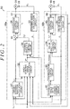
- the controller 50 will be described in more detail below. As illustrated in FIG. 2 , the controller 50 includes a reaction control circuit 50a and a steering control circuit 50b.
- the reaction control circuit 50a exercises reaction control.
- the steering control circuit 50b exercises steering control.
- the reaction control circuit 50a includes a target steering reaction calculation circuit 51, a target steering angle calculation circuit 52, a steering angle calculation circuit 53, a steering angle feedback control circuit 54, an adder 55, and an energization control circuit 56.
- the target steering reaction calculation circuit 51 calculates a target steering reaction T 1 * in accordance with the steering torque T h and the vehicle speed V.
- the target steering angle calculation circuit 52 calculates a target steering angle ⁇ * of the steering wheel 11 in accordance with the target steering reaction T 1 *, the steering torque T h , and the vehicle speed V.
- the target steering angle calculation circuit 52 includes an ideal model that defines an ideal steering angle in accordance with the input torque.
- Providing the ideal model may involve conducting, in advance, experiment(s) on a steering system including a power transmission path through which a steering wheel is mechanically coupled to steered wheels, so as to model a steering angle responsive to an ideal steered angle determined in accordance with the input torque.
- the target steering angle calculation circuit 52 adds up the target steering reaction T 1 * and the steering torque T h so as to determine the input torque.
- the target steering angle calculation circuit 52 calculates, from the input torque, the target steering angle ⁇ * in accordance with the ideal model.
- the steering angle calculation circuit 53 calculates the actual steering angle ⁇ s of the steering wheel 11 in accordance with the rotation angle ⁇ a of the reaction motor 31 detected by the rotation angle sensor 33.
- the steering angle feedback control circuit 54 calculates a steering angle correction amount T 2 * by performing feedback control for the steering angle ⁇ s such that the actual steering angle ⁇ s approaches or corresponds to the target steering angle ⁇ *.
- the adder 55 adds the steering angle correction amount T 2 * to the target steering reaction T 1 * so as to calculate a steering reaction command value T*.
- the energization control circuit 56 supplies power to the reaction motor 31.
- the power is responsive to the steering reaction command value T*.
- the energization control circuit 56 calculates a current command value for the reaction motor 31 in accordance with the steering reaction command value T*.
- the controller 50 includes a current sensor 57 disposed on a power supply path connected to the reaction motor 31. Using the current sensor 57, the energization control circuit 56 detects a current value I a of an actual current flowing through the power supply path.
- the energization control circuit 56 determines a difference between the current command value and the actual current value I a .
- the energization control circuit 56 controls supply of power to the reaction motor 31 (or performs feedback control for the current value I a ) so as to eliminate the difference between the current command value and the actual current value I a . This causes the reaction motor 31 to produce a torque responsive to the steering reaction command value T*. The driver is thus able to feel a moderate resistance responsive to a road surface reaction.
- the steering control circuit 50b includes a pinion angle calculation circuit 61, a steering angle ratio change control circuit 62, a compensation control circuit 63, a pinion angle feedback control circuit 64, and an energization control circuit 65.
- the pinion angle calculation circuit 61 calculates a pinion angle ⁇ p in accordance with the rotation angle ⁇ b of the steering motor 41 detected by the rotation angle sensor 43.
- the pinion angle ⁇ p is an actual rotation angle of the pinion shaft 44.
- the steering motor 41 and the pinion shaft 44 operate in conjunction with each other through the speed reducer 42.
- the rotation angle ⁇ b of the steering motor 41 thus has a correlation with the pinion angle ⁇ p of the pinion shaft 44. Using this correlation makes it possible to determine the pinion angle ⁇ p from the rotation angle ⁇ b of the steering motor 41.
- the pinion shaft 44 is in mesh with the steering operation shaft 14.
- the pinion angle ⁇ p thus has a correlation with a distance by which the steering operation shaft 14 moves.
- the pinion angle ⁇ p is a value reflective of the steered angle ⁇ w of the steered wheels 16.
- the steering angle ratio change control circuit 62 defines a steering angle ratio that is the ratio of the steered angle ⁇ w to the steering angle ⁇ s .
- the steering angle ratio change control circuit 62 calculates a target pinion angle in accordance with the steering angle ratio defined.
- the steering angle ratio change control circuit 62 calculates a target pinion angle ⁇ p * such that the lower the vehicle speed V, the greater the steered angle ⁇ w relative to the steering angle ⁇ s , and the higher the vehicle speed V, the smaller the steered angle ⁇ w relative to the steering angle ⁇ s .
- the steering angle ratio change control circuit 62 calculates a correction angle for the target steering angle ⁇ *.
- the steering angle ratio change control circuit 62 adds the correction angle to the target steering angle ⁇ * so as to calculate the target pinion angle ⁇ p * responsive to the steering angle ratio.
- the compensation control circuit 63 exercises control to enhance the response of the steered wheels 16 to an operation performed on the steering wheel 11, for example.
- the response of the steered wheels 16 to an operation performed on the steering wheel 11 will hereinafter be referred to as "steering responsiveness".
- the compensation control circuit 63 calculates a compensation amount for compensation of an inertia component, a viscosity component, and a spring component of the steering operation mechanism of the steering system 10.
- the compensation control circuit 63 adds the compensation amount to the target pinion angle ⁇ p * calculated by the steering angle ratio change control circuit 62.
- the compensation control circuit 63 thus calculates the final target pinion angle ⁇ p *.
- the compensation control circuit 63 will be described in more detail below.
- the pinion angle feedback control circuit 64 calculates a pinion angle command value T p * by performing feedback control (e.g., PID control) for the pinion angle ⁇ p such that the actual pinion angle ⁇ p approaches or corresponds to the final target pinion angle ⁇ p * calculated by the compensation control circuit 63.
- feedback control e.g., PID control
- the energization control circuit 65 supplies power to the steering motor 41.
- the power is responsive to the pinion angle command value T p *.
- the energization control circuit 65 calculates a current command value for the steering motor 41 in accordance with the pinion angle command value T p *.
- the controller 50 includes a current sensor 66 disposed on a power supply path connected to the steering motor 41. Using the current sensor 66, the energization control circuit 65 detects a current value I b of an actual current flowing through the power supply path.
- the term "current value I b" refers to the value of an actual current supplied to the steering motor 41.
- the energization control circuit 65 determines a difference between the current command value and the actual current value I b .
- the energization control circuit 65 controls supply of power to the steering motor 41 (or performs feedback control for the current value I b ) so as to eliminate the difference between the current command value and the actual current value I b . This causes the steering motor 41 to rotate by an angle responsive to the pinion angle command value T p *.
- the target steering angle calculation circuit 52 calculates, in accordance with the ideal model, the target steering angle ⁇ * from an input torque that is the sum of the target steering reaction T 1 * and the steering torque T h .
- the ideal model uses an input torque T in * that is a torque to be applied to the steering shaft 12.
- Equation (A) J denotes the inertia moment of the steering wheel 11 and the steering shaft 12
- C denotes a viscosity coefficient (or friction coefficient) for, for example, the friction of the steering operation shaft 14 against the housing
- K denotes a spring modulus determined when the steering wheel 11 and the steering shaft 12 are each regarded as a spring.
- calculation of the input torque T in * involves adding up the product of a second-order time differential value ⁇ *" of the target steering angle ⁇ * and the inertia moment J, the product of a first-order time differential value ⁇ *' of the target steering angle ⁇ * and the viscosity coefficient C, and the product of the target steering angle ⁇ * and the spring modulus K.
- the target steering angle calculation circuit 52 calculates the target steering angle ⁇ * in accordance with the ideal model based on Equation (A).
- the ideal model based on Equation (A) is divided into a steering model 71 and a vehicle model 72.
- the steering model 71 is tuned in accordance with the characteristics of components of the steering system 10, such as the steering shaft 12 and the reaction motor 31.
- the steering model 71 includes an adder 73, a subtracter 74, an inertia model 75, a first integrator 76, a second integrator 77, and a viscosity model 78.
- the adder 73 adds up the target steering reaction T 1 * and the steering torque T h so as to calculate the input torque T in *.
- the subtracter 74 subtracts a viscosity component T vi * and a spring component T sp * (which will be described below) from the input torque T in * calculated by the adder 73.
- the subtracter 74 thus calculates the final input torque T in *.
- the inertia model 75 functions as an inertia control calculation circuit associated with an inertia term of Equation (A).
- the inertia model 75 multiplies the final input torque T in *, calculated by the subtracter 74, by the inverse of the inertia moment J so as to calculate a steering angle acceleration ⁇ *.
- the first integrator 76 integrates the steering angle acceleration ⁇ * calculated by the inertia model 75.
- the first integrator 76 thus calculates a steering angle velocity ⁇ *.
- the second integrator 77 integrates the steering angle velocity ⁇ * calculated by the first integrator 76.
- the second integrator 77 thus calculates the target steering angle ⁇ *.
- the target steering angle ⁇ * is an ideal rotation angle of the steering wheel 11 (or the steering shaft 12) that is based on the steering model 71.
- the viscosity model 78 functions as a viscosity control calculation circuit associated with the viscosity term of Equation (A).
- the viscosity model 78 multiplies the steering angle velocity ⁇ *, calculated by the first integrator 76, by the viscosity coefficient C.
- the viscosity model 78 thus calculates the viscosity component T vi * to be subtracted from the input torque T in *.
- the vehicle model 72 is tuned in accordance with the characteristics of the vehicle equipped with the steering system 10.
- the characteristics of the vehicle that influence steering characteristics are determined in accordance with, for example, specifications of suspension and wheel alignment and the gripping force (or frictional force) of the steered wheels 16.
- the vehicle model 72 functions as a spring characteristic control calculation circuit associated with the spring term of Equation (A).
- the vehicle model 72 multiplies the target steering angle ⁇ *, calculated by the second integrator 77, by the spring modulus K.
- the vehicle model 72 thus calculates the spring component T sp * (torque) to be subtracted from the input torque T in *.
- the target steering angle calculation circuit 52 thus configured adjusts the inertia moment J and the viscosity coefficient C of the steering model 71 and the spring modulus K of the vehicle model 72. This makes it possible to directly tune the relationship between the input torque T in * and the target steering angle ⁇ *, thus providing desired steering characteristics.
- the present embodiment involves calculating the target pinion angle ⁇ p * using the target steering angle ⁇ * calculated from the input torque T in * in accordance with the steering model 71 and the vehicle model 72.
- the present embodiment then involves performing feedback control such that the actual pinion angle ⁇ p corresponds to the target pinion angle ⁇ p *.
- the pinion angle ⁇ p has a correlation with the steered angle ⁇ w of the steered wheels 16.
- the steering of the steered wheels 16 responsive to the input torque T in * is thus determined by the steering model 71 and the vehicle model 72.
- a vehicle steering response is determined by the steering model 71 and the vehicle model 72. Consequently, adjusting the steering model 71 and the vehicle model 72 makes it possible to provide a desired steering response.
- a steering reaction that is a force (or torque) exerted in a direction opposite to a direction in which the steering wheel 11 is turned by the driver is merely responsive to the target steering angle ⁇ *.
- the term "steering reaction” refers to a resistance felt by the driver through the steering wheel 11.
- the steering reaction does not change in accordance with a vehicle behavior or a road surface condition (such as road surface slippage). The driver thus finds it difficult to understand a vehicle behavior or a road surface condition through the steering reaction.
- the vehicle model 72 according to the present embodiment is configured as described below.
- the vehicle model 72 includes a virtual rack end axial force calculation circuit 90, an ideal axial force calculation circuit 91, an estimated axial force calculation circuit 92, an estimated axial force calculation circuit 93, an estimated axial force calculation circuit 94, an axial force distribution calculation circuit 95, and a conversion circuit 96.
- the virtual rack end axial force calculation circuit 90 calculates a virtual rack end axial force F end to limit the range of operation of the steering wheel 11 in a virtual sense.
- the virtual rack end axial force calculation circuit 90 calculates the virtual rack end axial force F end from the viewpoint of sharply increasing a torque to be produced by the reaction motor 31.
- the torque produced by the reaction motor 31 is exerted in a direction opposite to a direction in which the steering wheel 11 is turned by the driver. This torque will be referred to as a "steering reaction torque".
- the virtual rack end axial force calculation circuit 90 calculates the virtual rack end axial force F end using a virtual rack end map stored in a memory (not illustrated) of the controller 50.
- the virtual rack end axial force F end is produced when or after the target steering angle ⁇ * has reached an angle threshold value.
- the virtual rack end axial force F end sharply increases in response to an increase in the target steering angle ⁇ *.
- the ideal axial force calculation circuit 91 calculates an ideal axial force F1 in accordance with the target pinion angle ⁇ p *.
- the ideal axial force F1 is an ideal value of an axial force to be exerted on the steering operation shaft 14 through the steered wheels 16.
- the ideal axial force calculation circuit 91 calculates the ideal axial force F1 using an ideal axial force map stored in a memory (not illustrated) of the controller 50.
- the absolute value of the ideal axial force F1 to be calculated increases as the absolute value of the target pinion angle ⁇ p * increases (or the absolute value of a target steered angle that is the product of the target pinion angle ⁇ p * and a predetermined conversion factor increases).
- the absolute value of the ideal axial force F1 to be calculated may increase as the vehicle speed V decreases.
- the estimated axial force calculation circuit 92 calculates an estimated axial force F2 (or road surface reaction) in accordance with the current value I b of the steering motor 41.
- the estimated axial force F2 is exerted on the steering operation shaft 14.
- the current value I b of the steering motor 41 changes owing to a difference between the target pinion angle ⁇ p * and the actual pinion angle ⁇ p resulting from the action of a disturbance responsive to a road surface condition (such as a road surface frictional resistance) on the steered wheels 16.
- a road surface condition such as a road surface frictional resistance
- the estimated axial force calculation circuit 92 determines the estimated axial force F2 by multiplying the current value I b of the steering motor 41 by a gain that is a factor responsive to the vehicle speed V.
- the estimated axial force calculation circuit 93 calculates an estimated axial force F3 in accordance with a lateral acceleration LA detected by a lateral acceleration sensor 502 disposed on the vehicle.
- the estimated axial force F3 is exerted on the steering operation shaft 14.
- the estimated axial force calculation circuit 93 determines the estimated axial force F3 by multiplying the lateral acceleration LA by a gain that is a factor responsive to the vehicle speed V.
- the lateral acceleration LA is reflective of a road surface condition, such as a road surface frictional resistance.
- the estimated axial force F3 calculated in accordance with the lateral acceleration LA is thus reflective of an actual road surface condition.
- the estimated axial force calculation circuit 94 calculates an estimated axial force F4 in accordance with a yaw rate YR detected by a yaw rate sensor 503 disposed on the vehicle.
- the estimated axial force F4 is exerted on the steering operation shaft 14.
- the estimated axial force calculation circuit 94 determines the estimated axial force F4 by multiplying a yaw rate differential value by a vehicle speed gain.
- the yaw rate differential value is calculated by differentiating the yaw rate YR.
- the vehicle speed gain is a factor responsive to the vehicle speed V. The higher the vehicle speed V, the greater the vehicle speed gain.
- the yaw rate YR is reflective of a road surface condition, such as a road surface frictional resistance.
- the estimated axial force F4 calculated in accordance with the yaw rate YR is thus reflective of an actual road surface condition.
- the axial force distribution calculation circuit 95 multiples each of the virtual rack end axial force F end , the ideal axial force F1, the estimated axial force F2, the estimated axial force F3, and the estimated axial force F4 by a distribution ratio (or gain) defined for each of these forces.
- the axial force distribution calculation circuit 95 adds up the resulting products so as to calculate a final axial force F sp .
- the final axial force F sp is used for the calculation of the spring component T sp * to be subtracted from the input torque T in *.
- the distribution ratios are defined in accordance with various state quantities each reflective of a vehicle behavior, a road surface condition or a steering state.
- the conversion circuit 96 calculates (or converts) the spring component T sp * to be subtracted from the input torque T in *.
- the spring component T sp * based on the final axial force F sp is thus reflected in the input torque T in *. This makes it possible to provide a steering reaction responsive to a vehicle behavior or a road surface condition to the steering wheel 11.
- the compensation control circuit 63 will be described in detail. As illustrated in FIG. 5 , the compensation control circuit 63 includes four calculation circuits 101, 102, 103, 104, two differentiators 105, 106, and an adder 107.
- the calculation circuit 101 multiplies the target pinion angle ⁇ p *, calculated by the steering angle ratio change control circuit 62, by a gain G A so as to calculate a value ⁇ pa .
- K G denotes a mount rigidity of the steering operation mechanism.
- mount rigidity of the steering operation mechanism refers to rigidity of the steering operation mechanism supported on the body of the vehicle.
- the differentiator 105 differentiates the value ⁇ pa calculated by the calculation circuit 101. The differentiator 105 thus calculates a value ⁇ pa '.
- the differentiator 106 differentiates the value ⁇ pa ' calculated by the differentiator 105. The differentiator 106 thus calculates a value ⁇ pa ".
- the calculation circuit 102 multiplies the value ⁇ pa , calculated by the calculation circuit 101, by a gain G B .
- the calculation circuit 102 thus calculates a spring compensation amount (or rigidity compensation amount) ⁇ pb for compensation of the spring component (or rigidity component) of the steering operation mechanism.
- Equation (C) C ff denotes a cornering force C ff , and ⁇ denotes a trail.
- the calculation circuit 103 multiplies the value ⁇ pa ', calculated by the differentiator 105, by a gain G C .
- the calculation circuit 103 thus calculates a viscosity compensation amount ⁇ pc for compensation of the viscosity component of the steering operation mechanism.
- the calculation circuit 104 multiplies the value ⁇ pa ", calculated by the differentiator 106, by a gain G D .
- the calculation circuit 104 thus calculates an inertia compensation amount ⁇ pd for compensation of the inertia component of the steering operation mechanism.
- the spring compensation amount ⁇ pb , the viscosity compensation amount ⁇ pc , and the inertia compensation amount ⁇ pd are correction angles for the target pinion angle ⁇ p *.
- the adder 107 adds the spring compensation amount ⁇ pb , the viscosity compensation amount ⁇ pc , and the inertia compensation amount ⁇ pd to the target pinion angle ⁇ p * calculated by the steering angle ratio change control circuit 62. The adder 107 thus calculates the final target pinion angle ⁇ p *.
- the pinion angle feedback control circuit 64 calculates the pinion angle command value T p * by performing feedback control for the pinion angle ⁇ p in accordance with the final target pinion angle ⁇ p *. This compensates for the spring component, the viscosity component, and the inertia component of the steering operation mechanism of the steering system 10.
- the spring component results from, for example, the mount rigidity and cornering force of the steering operation mechanism.
- the viscosity component results from, for example, the viscosity of the steering operation mechanism (including the pinion shaft 44 and the steering operation shaft 14) and the viscosity of a kingpin.
- the inertia component results from, for example, the inertia of the steering operation mechanism and the inertia of the steered wheels 16.
- the target pinion angle ⁇ p * may also be referred to as a "target steered angle".
- the steered angle ⁇ wex is a comparative example.
- the steered angle ⁇ w is obtainable by multiplying the pinion angle ⁇ p by a predetermined conversion factor.
- the target steered angle is obtainable by multiplying the target pinion angle by a predetermined conversion factor.
- the steered angle ⁇ wex (comparative example) is a steered angle obtained when the compensation control circuit 63 is not included in the controller 50.
- compensating for the spring component of the steering operation mechanism results in a situation where the actual steered angle ⁇ w is closer to the target pinion angle ⁇ p * (target steered angle) than the steered angle ⁇ wex (comparative example). This is based on the fact that the spring component of the steering operation mechanism is exerted so as to further reduce the axial force of the steering operation shaft 14 with respect to the pinion angle ⁇ p .
- compensating for the viscosity component of the steering operation mechanism results in a situation where the phase of the actual steered angle ⁇ w is advanced such that the phase of the actual steered angle ⁇ w is closer to the phase of the target pinion angle ⁇ p * (target steered angle) than the phase of the steered angle ⁇ wex (comparative example).
- This is based on the fact that the viscosity component of the steering operation mechanism is exerted in a direction in which the axial force of the steering operation shaft 14 increases with respect to the pinion angle ⁇ p .
- compensating for the inertia component of the steering operation mechanism results in a situation where the amount of change in the actual steered angle ⁇ w (or inclination of the actual steered angle ⁇ w ) with respect to time is closer to the amount of change in the target pinion angle ⁇ p * (target steered angle) with respect to time than the amount of change in the steered angle ⁇ wex (comparative example) with respect to time.
- This is based on the fact that the inertia component of the steering operation mechanism is exerted so as to further reduce the degree of change in the axial force of the steering operation shaft 14 with respect to an increase in the pinion angle ⁇ p .
- the steered angle ⁇ w thus changes such that the steered angle ⁇ w is closer to the target pinion angle ⁇ p * (target steered angle) than the steered angle ⁇ wex (comparative example).
- the first embodiment achieves effects described below.
- the differential steering control circuit exercises “differential steering control".
- the differential steering control involves: multiplying the rate of change in the target pinion angle ⁇ p * (i.e., the differential value of the target pinion angle ⁇ p *), calculated by the steering angle ratio change control circuit 62, by a gain so as to calculate a correction angle; and adding the correction angle to the target pinion angle ⁇ p * calculated by the steering angle ratio change control circuit 62. Exercising such differential steering control advances the phase of the target pinion angle ⁇ p *. This reduces or eliminates steering delay.
- Differential steering control is intended to compensate for the viscosity component of the steering operation mechanism (including the pinion shaft 44 and the steering operation shaft 14). Advancing the phase of the target pinion angle ⁇ p * may thus reduce or eliminate steering delay as indicated by the arrow P2 in the graph of FIG. 6 .
- Differential steering control known in the related art unfortunately fails to provide compensation for the spring component of the steering operation mechanism indicated by the arrow P1 in the graph of FIG. 6 or compensation for the inertia component of the steering operation mechanism indicated by the arrow P3 in the graph of FIG. 6 .
- the spring component and the inertia component may affect steering responsiveness of the steered wheels 16 to an operation performed on the steering wheel 11 or proper steering operation of the steered wheels 16.
- the compensation control circuit 63 compensates for not only the viscosity component of the steering operation mechanism but also the spring component and the inertia component of the steering operation mechanism.
- the compensation control circuit 63 is thus able to increase the steering responsiveness of the steered wheels 16.
- the compensation control circuit 63 also causes the steered wheels 16 to be properly steered in accordance with the target pinion angle ⁇ p *.
- the gains G A , G B , G C and G D may be determined as follows.
- the gain G A may be determined using at least one or more of spring components in a power transmission path between the pinion shaft 44 and the steered wheels 16. This means that the gain G A may be determined in accordance with two or more spring components.
- the cornering force C ff in each of Equations (C), (C1), and (C3) may be estimated from a tire lateral force detected by a tire force detector (not illustrated). Alternatively, the cornering force C ff in each of Equations (C), (C1), and (C3) may be a constant.
- the trail ⁇ in each of Equations (C), (C2), and (C3) may be estimated from a tire lateral force detected by the tire force detector (not illustrated) and a moment around a vertical axis of each steered wheel 16. Alternatively, the trail ⁇ in each of Equations (C), (C2), and (C3) may be a constant.
- the gains G B , G C , and G D may be changed in accordance with the vehicle speed V detected by the vehicle speed sensor 501 or a load detected by the tire force detector (not illustrated).
- a steering controller according to a second embodiment of the invention will be described below.
- the steering controller according to the second embodiment is similar in basic configuration to the steering controller according to the first embodiment illustrated in FIGS. 1 to 5 .
- the steered wheels 16 are steered in a first steered direction and are steered in a second steered direction opposite to the first steered direction.
- the sign of a torque exerted on the steering operation shaft 14 so as to cause the steered wheels 16 (or tires) to be steered in the first steered direction is opposite to the sign of a torque exerted on the steering operation shaft 14 so as to cause the steered wheels 16 (or tires) to be steered in the second steered direction.
- the sign of the spring compensation amount ⁇ pb calculated by the calculation circuit 102 is preferably inverted in accordance with a steered state (or a steered direction).
- first steered direction refers to a direction in which the steered wheels 16 are steered when the steering wheel 11 is turned in a first steering direction from a neutral position toward a steering limit.
- second steered direction refers to a direction in which the steered wheels 16 are steered when the steering wheel 11 is turned in a second steering direction opposite to the first steering direction.
- the steered state of the steered wheels 16 can be determined in accordance with a determination value H p that is the product of a pinion torque T p and a pinion angular velocity (or steered velocity) ⁇ p .
- the steered wheels 16 When the determination value H p is positive, the steered wheels 16 are in a first steered state where the steered wheels 16 are steered in the first steered direction. When the determination value H p is negative, the steered wheels 16 are in a second steered state where the steered wheels 16 are steered in the second steered direction. When the determination value H p is zero, the steered wheels 16 are in a state where the steered angle ⁇ w of the steered wheels 16 is maintained at a constant value. Based on these premises, the compensation control circuit 63 according to the second embodiment is configured as described below.
- the compensation control circuit 63 includes a differentiator 111, a multiplier 112, a gain calculation circuit 113, and a multiplier 114 in addition to the components illustrated in FIG. 5 .
- the differentiator 111 differentiates the pinion angle ⁇ p calculated by the pinion angle calculation circuit 61. The differentiator 111 thus calculates the pinion angular velocity ⁇ p .
- the multiplier 112 multiplies the pinion torque T p by the pinion angular velocity ⁇ p so as to calculate the determination value H p indicative of the steered state.
- the gain calculation circuit 113 calculates a gain G h responsive to the determination value H p using a gain map M G .
- the gain map M G defines the relationship between the determination value H p and the gain G h .
- the gain map M G is set such that the positive gain G h is calculated when the determination value H p is positive, and the negative gain G h is calculated when the determination value H p is negative.
- the absolute value of the gain G h is 1.
- the multiplier 114 multiplies the spring compensation amount ⁇ pb , calculated by the calculation circuit 102, by the gain G h so as to calculate the final spring compensation amount ⁇ pb .
- the determination value H p is positive (1), i.e., when the steered wheels 16 are in the first steered state, the final spring compensation amount ⁇ pb is positive.
- the determination value H p is negative (-1), i.e., when the steered wheels 16 are in the second steered state, the final spring compensation amount ⁇ pb is negative.
- the second embodiment achieves effects described below.
- (2) The sign of the spring compensation amount ⁇ pb calculated by the calculation circuit 102 is inverted in accordance with the determination value H p . This makes it possible to suitably compensate for the spring component of the steering operation mechanism not only when the steered wheels 16 are steered in the first steered direction but also when the steered wheels 16 are steered in the second steered direction.
- the determination value H p may be calculated in accordance with any one of Equations (F1), (F2), and (F3).
- H p T p ⁇ ⁇ p ⁇ G 1 + dT p ⁇ ⁇ p ⁇ G 2
- Equation (F1) dT p denotes a differential value of the pinion torque T p , ⁇ p denotes a pinion angle, G 1 denotes a predetermined gain, and G 2 denotes another predetermined gain.
- H p T h ⁇ ⁇ s
- T h denotes a steering torque
- ⁇ s denotes a steering speed.
- the steering speed ⁇ s is calculated by differentiating the steering angle ⁇ s .
- H p T h ⁇ ⁇ s ⁇ G 1 + dT p ⁇ ⁇ s ⁇ G 2
- the sign of the final spring compensation amount ⁇ pb is decided by multiplying the spring compensation amount ⁇ pb , calculated by the calculation circuit 102, by the gain G h .
- the calculation circuit 102 may invert the sign of the gain G B in accordance with the gain G h .
- a steering controller according to a third embodiment of the invention will be described below.
- the steering controller according to the third embodiment is similar in basic configuration to the steering controller according to the first embodiment illustrated in FIGS. 1 to 5 .
- the third embodiment involves determining the steered state using various pieces of information on the steered side of the steering system 10.
- the determination value H p indicative of the steered state can be calculated in accordance with Equation (G1) or (G2).
- H p X 1 ⁇ X 2
- Equation (G1) one of state quantities (a 1 ) to (a 13 ) described below or the product of two or more of the state quantities (a 1 ) to (a 13 ) is substituted into X 1 .
- the differential value of one of the state quantities (a 1 ) to (a 13 ) or the product of the differential values of two or more of the state quantities (a 1 ) to (a 13 ) is substituted into X 2 . Any combination of the state quantities (a 1 ) to (a 13 ) is effective.
- H p Y 1 + Y 2
- Equation (G2) the product of one of the state quantities (a 1 ) to (a 13 ) and a predetermined gain or the product of values obtained by multiplying each of two or more of the state quantities (a 1 ) to (a 13 ) by a predetermined gain is substituted into Y 1 .
- the product of the differential value of one of the state quantities (a 1 ) to (a 13 ) and a predetermined gain or the product of values obtained by multiplying the differential value of each of two or more of the state quantities (a 1 ) to (a 13 ) by a predetermined gain is substituted into Y 2 . Any combination of the state quantities (a 1 ) to (a 13 ) is effective.
- the state quantity (a 1 ) is the target pinion angle ⁇ p * (or target steered angle).
- the state quantity (a 2 ) is the pinion angle ⁇ p (or steered angle).
- the state quantity (a 3 ) is the pinion angle command value T p * (or current command value).
- the state quantity (a 4 ) is the current value I b of the steering motor 41.
- the state quantity (a 5 ) is the estimated axial force F2.
- the state quantity (a 6 ) is the lateral acceleration LA.
- the state quantity (a 7 ) is the estimated axial force F3.
- the state quantity (a 8 ) is the yaw rate YR.
- the state quantity (a 9 ) is the estimated axial force F4.
- the state quantity (a 10 ) is an estimated axial force based on the differential value of the lateral acceleration LA and the differential value of the yaw rate YR.
- the state quantity (a 11 ) is the ideal axial force F1.
- the state quantity (a 12 ) is a lateral force of the steered wheels 16.
- the state quantity (a 13 ) is a self-aligning torque of the steered wheels 16.
- the self-aligning torque may be a detection value or estimated value.
- the controller 50 of the steering system 10 exercises reaction control and steering control in accordance with the steering state. Accordingly, the controller 50 is required to exercise reaction control and steering control in consideration of the steered state depending on product specifications, for example.
- the third embodiment thus involves using the determination value H p responsive to the steered state (i.e., the first steered state or the second steered state) so as to calculate control parameter(s) to be used when the controller 50 exercises reaction control and steering control.
- the determination value H p in this case is calculated using the current value I b of the steering motor 41 and the differential value of the pinion angle ⁇ p in Equation (G1).
- the differential value of the pinion angle ⁇ p corresponds to the pinion angular velocity ⁇ p .
- the current value I b of the steering motor 41 is the state quantity (a 4 ).
- the pinion angle ⁇ p is the state quantity (a 2 ).
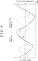
- the graph of FIG. 9 illustrates exemplary changes in the pinion angle ⁇ p and the determination value H p with respect to time.
- the determination value H p is positive when the steered wheels 16 are in the first steered state, i.e., when the absolute value of the pinion angle ⁇ p increases relative to zero degrees corresponding to a neutral steered position.
- the determination value H p is negative when the steered wheels 16 are in the second steered state, i.e., when the absolute value of the pinion angle ⁇ p approaches zero degrees.
- the determination value H p is zero when the pinion angle ⁇ p has reached zero degrees (i.e., when the steered wheels 16 are located at the neutral steered position) or when the pinion angle ⁇ p is an angle at which the vehicle travels forward.
- the controller 50 (or more specifically, the reaction control circuit 50a) includes a differentiator 121, a multiplier 122, a gain calculation circuit 123, and a multiplier 124.
- the differentiator 121 differentiates the pinion angle ⁇ p calculated by the pinion angle calculation circuit 61. The differentiator 121 thus calculates the pinion angular velocity ⁇ p .
- the multiplier 122 multiplies the current value I b of the steering motor 41 by the pinion angular velocity ⁇ p so as to calculate the determination value H p indicative of the steered state (or steered direction).
- the gain calculation circuit 123 calculates a gain G h2 responsive to the determination value H p using a gain map M G2 .
- the gain map M G2 defines the relationship between the determination value H p and the gain G h2 .
- the gain map M G2 is set such that a gain G h21 is calculated when the determination value H p is positive and a gain G h22 is calculated when the determination value H p is negative.
- Each of the gains G h21 and G h22 is a positive value.
- the gain G h21 is smaller than the gain G h22 .
- the multiplier 124 multiplies the target steering reaction T 1 *, calculated by the target steering reaction calculation circuit 51, by the gain G h2 so as to calculate the final target steering reaction T 1 *. Using the final target steering reaction T 1 * calculated by the multiplier 124 enables the controller 50 to exercise suitable reaction control and steering control in accordance with the steered state.
- the third embodiment achieves effects described below.
- the controller 50 estimates the steered state (i.e., whether the steered wheels 16 are in the first steered state or the second steered state) and multiplies the control parameter (i.e., the target steering reaction T 1 * in the third embodiment) by the gain G h2 responsive to the steered state estimated.
- the control parameter responsive to the steered state enables the controller 50 to exercise suitable steering control responsive to the steered state and suitable reaction control responsive to the steered state.
- the third embodiment enhances control performance for both of steering control and reaction control.
- An element to calculate the determination value H p i.e., an element equivalent to the multiplier 122
- an element to calculate the gain G h2 i.e., an element equivalent to the gain calculation circuit 123 are preferably provided in association with at least one of the calculation circuits and control circuits of the controller 50 in accordance with product specifications, for example.
- the element to calculate the determination value H p and the element to calculate the gain G h2 may be provided in one of the calculation circuits and control circuits of the controller 50 other than the target steering reaction calculation circuit 51, or may be provided in association with all of the calculation circuits and control circuits of the controller 50 or two or more, but not all, of the calculation circuits and control circuits of the controller 50. In the example illustrated in FIG. 2 , the number of calculation circuits and control circuits of the controller 50 is 10 in total.
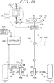
- a vehicle controller according to a fourth embodiment of the invention is included in an electric power steering system 150 (hereinafter referred to as an "EPS 150").
- the EPS 150 including the vehicle controller according to the fourth embodiment will be described below. Components similar to those of the first embodiment are identified by the same reference signs, and detailed description thereof will be omitted.
- the EPS 150 includes the steering shaft 12, the pinion shaft 13, and the steering operation shaft 14 that function as a power transmission path between the steering wheel 11 and the steered wheels 16.
- a reciprocating rectilinear motion of the steering operation shaft 14 is transmitted to the right and left steered wheels 16 through the tie rods 15 each coupled to an associated one of the ends of the steering operation shaft 14.
- the EPS 150 includes an assist motor 151, a speed reducer 152, the torque sensor 34, a rotation angle sensor 153, and a controller 154 that function as a steering assist force generator to generate a steering assist force (which may also be referred to as an "assist force").
- the rotation angle sensor 153 is disposed on the assist motor 151.
- the rotation angle sensor 153 detects a rotation angle ⁇ m of the assist motor 151.
- the assist motor 151 is a source of the steering assist force.
- Examples of the assist motor 151 to be used include a three-phase brushless motor.
- the assist motor 151 is coupled to the pinion shaft 44 through the speed reducer 152.
- the speed reducer 152 reduces the speed of rotation of the assist motor 151.
- the resulting rotational force is transmitted from the pinion shaft 44 to the pinion shaft 13 through the steering operation shaft 14. This rotational force is transmitted in the form of the steering assist force.
- the controller 154 exercises assist control to produce a steering assist force responsive to the steering torque T h by performing energization control for the assist motor 151.
- the controller 154 controls supply of power to the assist motor 151 in accordance with the steering torque T h detected by the torque sensor 34, the vehicle speed V detected by the vehicle speed sensor 501, and the rotation angle ⁇ m detected by the rotation angle sensor 153.
- the controller 154 includes a pinion angle calculation circuit 161, a basic assist component calculation circuit 162, a target pinion angle calculation circuit 163, a pinion angle feedback control circuit (or pinion angle F/B control circuit) 164, an adder 165, and an energization control circuit 166.
- the pinion angle calculation circuit 161 receives the rotation angle ⁇ m of the assist motor 151. In accordance with the rotation angle ⁇ m received, the pinion angle calculation circuit 161 calculates the pinion angle ⁇ p that is a rotation angle of the pinion shaft 44.
- the basic assist component calculation circuit 162 calculates a basic assist component T a1 * in accordance with the steering torque T h and the vehicle speed V.
- the basic assist component calculation circuit 162 calculates the basic assist component T a1 * using a three-dimensional map that defines the relationship between the steering torque T h and the basic assist component T a1 * in accordance with the vehicle speed V.
- the greater the absolute value of the steering torque T h the greater the absolute value of the basic assist component T a1 * calculated by the basic assist component calculation circuit 162.
- the lower the vehicle speed V the greater the absolute value of the basic assist component T a1 * calculated by the basic assist component calculation circuit 162.
- the target pinion angle calculation circuit 163 receives the basic assist component T a1 * calculated by the basic assist component calculation circuit 162 and the steering torque T h . Assuming that the sum of the basic assist component T a1 * and the steering torque T h is an input torque, the target pinion angle calculation circuit 163 includes an ideal model that defines an ideal pinion angle in accordance with the input torque. Providing the ideal model involves conducting, for example, experiment(s) in advance so as to model a pinion angle responsive to an ideal steered angle determined in accordance with the input torque. The target pinion angle calculation circuit 163 adds up the basic assist component T a1 * and the steering torque T h so as to determine the input torque.
- the target pinion angle calculation circuit 163 calculates, from the input torque determined, the target pinion angle ⁇ p * in accordance with the ideal model. In calculating the target pinion angle ⁇ p *, the target pinion angle calculation circuit 163 factors in the vehicle speed V and a current value I m detected by a current sensor 167.
- the current sensor 167 is disposed on a power supply path connected to the assist motor 151.
- the current value I m is the value of an actual current supplied to the assist motor 151.
- the pinion angle feedback control circuit 164 receives the target pinion angle ⁇ p * calculated by the target pinion angle calculation circuit 163 and the actual pinion angle ⁇ p calculated by the pinion angle calculation circuit 161.
- the pinion angle feedback control circuit 164 performs proportional-integral-differential (PID) control in the form of pinion angle feedback control such that the actual pinion angle ⁇ p approaches or corresponds to the target pinion angle ⁇ p *.
- PID proportional-integral-differential
- the pinion angle feedback control circuit 164 determines a difference between the target pinion angle ⁇ p * and the actual pinion angle ⁇ p .
- the pinion angle feedback control circuit 164 calculates a correction component T a2 * to be added to the basic assist component T a1 * so as to eliminate the difference.
- the adder 165 adds the correction component T a2 * to the basic assist component T a1 * so as to calculate an assist command value T a *.
- the assist command value T a * is indicative of a rotational force (or assist torque) to be produced by the assist motor 151.
- the energization control circuit 166 supplies power to the assist motor 151.
- the power is responsive to the assist command value T a *.
- the energization control circuit 166 calculates a current command value for the assist motor 151 in accordance with the assist command value T a *.
- the energization control circuit 166 receives the current value I m detected by the current sensor 167.
- the energization control circuit 166 determines a difference between the current command value and the actual current value I m .
- the energization control circuit 166 controls supply of power to the assist motor 151 so as to eliminate the difference.
- the assist motor 151 thus produces a torque responsive to the assist command value T a *. This consequently provides a steering assist responsive to the steering state.
- the controller 154 of the EPS 150 calculates the target pinion angle ⁇ p * from the input torque (i.e., the sum of the basic assist component T a1 * and the steering torque T h ) and performs feedback control such that the actual pinion angle ⁇ p corresponds to the target pinion angle ⁇ p *.
- the pinion angle ⁇ p has a correlation with a steered angle ⁇ t of the steered wheels 16.
- the steering of the steered wheels 16 responsive to the input torque is thus determined in accordance with the ideal model. This means that a vehicle steering response is determined in accordance with the ideal model. Consequently, adjusting the ideal model makes it possible to provide a desired steering response.
- the EPS 150 maintains the actual steered angle ⁇ t at the steered angle ⁇ t responsive to the target pinion angle ⁇ p *. This achieves the effect of reducing or eliminating reverse input vibrations resulting from a disturbance, such as a road surface condition or braking.
- the correction component T a2 * would be adjusted such that the pinion angle ⁇ p corresponds to the target pinion angle ⁇ p *, if vibrations are transmitted to components of the steering operation mechanism, such as the steering shaft 12, through the steered wheels 16.
- the actual steered angle ⁇ t is thus maintained at the steered angle ⁇ t responsive to the target pinion angle ⁇ p * defined by the ideal model. This consequently provides a steering assist in a direction in which reverse input vibrations are cancelled, preventing the reverse input vibrations from being transmitted to the steering wheel 11.
- a steering reaction i.e., a resistance felt by the driver through the steering wheel 11
- the steering reaction is merely responsive to the target pinion angle ⁇ p *.
- the steering reaction does not change in accordance with a road surface condition, such as a dry road or a low friction road. This makes it difficult for the driver to understand a road surface condition by feeling a resistance while he or she is turning the steering wheel 11.
- the target pinion angle calculation circuit 163 according to the fourth embodiment has the calculation function of the target steering angle calculation circuit 52 according to the first embodiment.
- the target pinion angle calculation circuit 163 is similar in functional configuration to the target steering angle calculation circuit 52 illustrated in FIG. 3 .
- the target steering angle calculation circuit 52 according to the first embodiment receives the target steering reaction T 1 *, but the target pinion angle calculation circuit 163 according to the fourth embodiment receives the basic assist component T a1 *.
- the target steering angle calculation circuit 52 according to the first embodiment receives the current value I b of a current supplied to the steering motor 41, but the target pinion angle calculation circuit 163 according to the fourth embodiment receives the current value I m of a current supplied to the assist motor 151.
- the target pinion angle calculation circuit 163 receives the steering torque T h and the vehicle speed V.
- the target steering angle calculation circuit 52 according to the first embodiment calculates the target steering angle ⁇ *, but the target pinion angle calculation circuit 163 according to the fourth embodiment calculates the target pinion angle ⁇ p *.
- the target pinion angle calculation circuit 163 performs an internal calculation process in the same manner as the target steering angle calculation circuit 52 according to the first embodiment.
- the EPS 150 may be provided with a variable-gear-ratio (VGR) mechanism 170.
- VGR variable-gear-ratio
- a VGR motor 171 is disposed on a portion of the steering shaft 12 located between the steering wheel 11 and the torque sensor 34.
- the VGR mechanism 170 changes the ratio between the steering angle ⁇ s and the steered angle ⁇ t (which is a gear ratio) using the VGR motor 171.
- the VGR motor 171 includes a stator 171a and a rotor 171b.
- the steering shaft 12 includes an input shaft 12a and an output shaft 12b.
- the input shaft 12a is a portion of the steering shaft 12 adjacent to the steering wheel 11.
- the output shaft 12b is a portion of the steering shaft 12 adjacent to the pinion shaft 13.
- the stator 171a of the VGR motor 171 is coupled to the input shaft 12a.
- the rotor 171b of the VGR motor 171 is coupled to the output shaft 12b.
- Equation (H) ⁇ s denotes a steering angle, and ⁇ g denotes a rotation angle of the VGR motor 171. Accordingly, controlling the rotation angle ⁇ g of the VGR motor 171 provides any desired gear ratio.
- the target pinion angle calculation circuit 163 functions as a target steering angle calculation circuit to calculate the sum of the steering angle ⁇ s and the rotation angle ⁇ g of the VGR motor 171 (i.e., a target value for the rotation angle ⁇ sg of the output shaft 12b relative to the input shaft 12a).
- the target pinion angle calculation circuit 163 functioning as the target steering angle calculation circuit uses the sum of the steering speed ⁇ s and the rotation speed of the VGR motor 171.
- the pinion angle feedback control circuit 164 functions as a steering angle feedback control circuit to determine a difference between the target value for the rotation angle ⁇ sg and the actual rotation angle ⁇ sg and calculate the correction component T a2 * to be added to the basic assist component T a1 * so as to eliminate the difference.
- the controller 154 of the EPS 150 including the VGR mechanism 170 is provided with a steering angle ratio change control circuit and a differential steering control circuit.
- the steering angle ratio change control circuit and the differential steering control circuit serve to control the VGR motor 171.
- the steering angle ratio change control circuit calculates a target rotation angle of the VGR motor 171 in accordance with the steering angle ⁇ s and the vehicle speed V, for example.
- the differential steering control circuit corrects the target rotation angle of the VGR motor 171 in accordance with the steering speed ⁇ s and the vehicle speed V so as to calculate the final target rotation angle.
- the controller 154 controls supply of power to the VGR motor 171 by performing feedback control such that the actual rotation angle of the VGR motor 171 corresponds to the target rotation angle.
- the controller 154 may be provided with no differential steering control circuit to control the VGR motor 171.
- the controller 154 may have a calculation function similar to the calculation function of the compensation control circuit 63 illustrated in FIG. 5 or FIG. 7 .
- the controller 154 of the EPS 150 may have calculation functions similar to the calculation functions of the controller 50 illustrated in FIG. 8 (e.g., the calculation functions of the multiplier 122 to calculate the determination value H p indicative of the steered state and the gain calculation circuit 123 to calculate the gain G h2 ).
- the controller 154 of the EPS 150 thus achieves effects similar to those of the first to third embodiments described above.
- the fourth embodiment may be modified as described below.
- the fourth embodiment has been described on the assumption that the EPS 150 provides a steering assist force to the steering operation shaft 14.
- the EPS 150 may be configured to provide a steering assist force to the steering shaft 12.
- the following description discusses a variation of the fourth embodiment involving providing a steering assist force to the steering shaft 12.
- the assist motor 151 is coupled not to the steering operation shaft 14 but to the steering shaft 12 through the speed reducer 152 as indicated by the associated long dashed double-short dashed lines in FIG. 10 .
- the EPS 150 may include no pinion shaft 44.
- the controller 154 exercises feedback control for the steering angle ⁇ s instead of feedback control for the pinion angle ⁇ p .
- the pinion angle calculation circuit 161 functions as a steering angle calculation circuit to calculate the steering angle ⁇ s in accordance with the current value I m of the assist motor 151.
- the target pinion angle calculation circuit 163 functions as a target steering angle calculation circuit to calculate a target steering angle (i.e., a target value for the steering angle ⁇ s ) in accordance with the steering torque T h , the vehicle speed V, the basic assist component T a1 *, and the current value I m .
- the target steering angle calculation circuit is similar in basic configuration to the target steering angle calculation circuit 52 illustrated in FIG. 3 .
- the controller 154 is provided with a differentiator 79.
- the differentiator 79 differentiates the steering angle ⁇ s so as to calculate the steering speed ⁇ s .
- the pinion angle feedback control circuit 164 functions as a steering angle feedback control circuit to determine a difference between the target steering angle and the actual steering angle ⁇ s and calculate the correction component T a2 * to be added to the basic assist component T a1 * so as to eliminate the difference.
- the target steering reaction calculation circuit 51 determines the target steering reaction T 1 * in accordance with the steering torque T h and the vehicle speed V. Alternatively, the target steering reaction calculation circuit 51 may determine the target steering reaction T 1 * in accordance with only the steering torque T h .
- the basic assist component calculation circuit 162 according to the fourth embodiment determines the basic assist component T a1 * in accordance with the steering torque T h and the vehicle speed V. Alternatively, the basic assist component calculation circuit 162 may determine the basic assist component T a1 * in accordance with only the steering torque T h .
- the vehicle model 72 (see FIG. 4 ) preferably includes at least one of the three estimated axial force calculation circuits (i.e., the estimated axial force calculation circuits 92, 93, and 94).
- the estimated axial force calculated by any one of the estimated axial force calculation circuits 92, 93, and 94 is reflected in the input torque T in *, making it possible to provide a steering reaction reflective of a vehicle behavior or a road surface condition.
- the steering system 10 may be provided with a clutch 21.
- the clutch 21 to be used is an electromagnetic clutch that transmits or cuts off power in response to energization or non-energization of an exciting coil.
- the controller 50 exercises clutch engaging and disengaging control to perform switching between engagement and disengagement of the clutch 21. Disengaging the clutch 21 mechanically disconnects the steering wheel 11 from the steered wheels 16. Engaging the clutch 21 mechanically connects the steering wheel 11 to the steered wheels 16.
- Each of the first to third embodiments involves compensating for all of the spring component, the viscosity component, and inertia component of the steering operation mechanism.
- An alternative embodiment may involve compensating for at least one of the spring component, the viscosity component, and inertia component in accordance with product specifications, for example.
- One example preferably involves compensating for only the inertia component when the inertia component significantly affects the steering of the steered wheels 16 but the influence of the viscosity component and spring component is negligible.
- Another example preferably involves compensating for only the inertia component and the spring component when the inertia component and the spring component significantly affect the steering of the steered wheels 16 but the influence of the viscosity component is negligible.
Landscapes
- Engineering & Computer Science (AREA)
- Chemical & Material Sciences (AREA)
- Combustion & Propulsion (AREA)
- Transportation (AREA)
- Mechanical Engineering (AREA)
- Physics & Mathematics (AREA)
- Mathematical Physics (AREA)
- Steering Control In Accordance With Driving Conditions (AREA)
- Power Steering Mechanism (AREA)
Abstract
Description
- The invention relates to steering controllers.
- A "steer-by-wire" steering system is known in the related art. In the steer-by-wire steering system, a steering wheel is mechanically disconnected from steered wheel(s). Such a steering system includes a reaction motor and a steering motor. The reaction motor functions as a source of a steering reaction to be provided to a steering shaft. The steering motor functions as a source of a steering force to steer steered wheel(s). During travel of a vehicle, a controller for the steering system exercises not only reaction control to produce a steering reaction from the reaction motor but also steering control to steer the steered wheel(s) using the steering motor. Such a controller will hereinafter be referred to as a "steering controller".
- Japanese Patent Application Publication No.
2014-151881 JP 2014-151881 A - Various vehicle-mounted controllers have recently been developed to enhance the performance of vehicles. In connection with this, studies are being conducted on steering controllers with the aim of further improving steering response (i.e., operations of steered wheels responsive to steering operations performed on steering wheels).
- An object of the invention is to provide a steering controller that is able to effect proper steering of steered wheel(s).
- An aspect of the invention provides a steering controller to control a motor in accordance with a command value calculated in response to a steering state. The motor is a source of a driving force to be provided to a steering operation mechanism configured to steer a steered wheel of a vehicle. The steering controller includes a compensation control circuit to calculate a compensation amount in response to the steering state so as to compensate for at least one of an inertia component, a viscosity component, and a spring component of the steering operation mechanism in accordance with a target rotation angle of a rotator. The compensation amount is to be reflected in the command value. The rotator is configured to rotate in conjunction with steering of the steered wheel.
- The magnitude of influence of an inertia component, a viscosity component, and a spring component on steering of steered wheels may differ for each mechanism to steer the steered wheels. Differential steering control known in the related art may thus fail to reduce or eliminate the influence of an inertia component, a viscosity component, and a spring component on steering of steered wheels.
- In this respect, the steering controller described above is configured such that the command value is reflective of the compensation amount for compensation of at least one of the inertia component, the viscosity component, and the spring component of the mechanism to steer the steered wheel. One example may involve compensating for only the inertia component when the inertia component significantly affects the steering of the steered wheel but the influence of the viscosity component and spring component is negligible. Another example may involve compensating for only the inertia component and the spring component when the inertia component and the spring component significantly affect the steering of the steered wheel but the influence of the viscosity component is negligible. Still another example may involve compensating for all of the inertia component, the viscosity component, and the spring component when all of the inertia component, the viscosity component, and the spring component affect the steering of the steered wheel. Thus, selectively compensating for the inertia component, the viscosity component, and the spring component in accordance with the characteristics of the mechanism to steer the steered wheel makes it possible to suitably reduce or eliminate any one, two, or all of the inertia component, the viscosity component, and the spring component that affect(s) the steering of the steered wheel. Accordingly, the steering controller controls the motor in accordance with the command value reflective of the compensation amount so as to effect proper steering of the steered wheel. This also provides proper steering response of the steered wheel.
- The steering controller may further include a first calculation circuit and a second calculation circuit. The first calculation circuit may be configured to calculate the target rotation angle of the rotator in accordance with the steering state. The second calculation circuit may be configured to calculate the command value by performing feedback control such that an actual rotation angle of the rotator corresponds to the target rotation angle. The compensation control circuit may include a compensation amount calculation circuit and an adder. The compensation amount calculation circuit may be configured to calculate the compensation amount in accordance with the target rotation angle calculated by the first calculation circuit. The adder may be configured to add the compensation amount to the target rotation angle so as to calculate a final target rotation angle to be used for the calculation of the command value. The compensation amount may be calculated by the compensation amount calculation circuit. The target rotation angle may be calculated by the first calculation circuit. Thus, the compensation amount calculated by the compensation amount calculation circuit is added to the target rotation angle calculated by the first calculation circuit. Consequently, the command value is reflective of the compensation amount.
- The motor of the steering controller may be a steering motor to provide a driving force to a steering operation shaft. The steering operation shaft is a component of the steering operation mechanism. When a driving force is provided to the steering operation shaft located away from a steering wheel, compensating for at least one of the inertia component, the viscosity component, and the spring component in the manner described above is effective in causing the steered wheel to be steered properly.
- The foregoing and further features and advantages of the invention will become apparent from the following description of example embodiments with reference to the accompanying drawings, wherein like numerals are used to represent like elements and wherein:
-
FIG. 1 is a schematic diagram illustrating a steer-by-wire steering system equipped with a steering controller according to a first embodiment of the invention; -
FIG. 2 is a control block diagram of a controller according to the first embodiment; -
FIG. 3 is a control block diagram of a target steering angle calculation circuit according to the first embodiment; -
FIG. 4 is a control block diagram of a vehicle model according to the first embodiment; -
FIG. 5 is a control block diagram of a compensation control circuit according to the first embodiment; -
FIG. 6 is a graph illustrating changes in target steered angle and actual steered angle with respect to time in the first embodiment; -
FIG. 7 is a control block diagram illustrating main components of the compensation control circuit according to a second embodiment of the invention; -
FIG. 8 is a control block diagram illustrating main components of the controller according to a third embodiment of the invention; -
FIG. 9 is a graph illustrating changes in pinion angle and steered state determination value with respect to time in the third embodiment; -
FIG. 10 is a schematic diagram illustrating an electric power steering system equipped with a steering controller according to a fourth embodiment of the invention; and -
FIG. 11 is a control block diagram of the steering controller according to the fourth embodiment. - A first embodiment of the invention involves using a steering controller in a steer-by-wire steering system. The steering controller is a
controller 50. The steer-by-wire steering system is asteering system 10 for a vehicle. - As illustrated in
FIG. 1 , thevehicle steering system 10 includes asteering wheel 11 and a steeringshaft 12 coupled to thesteering wheel 11. Thesteering system 10 further includes asteering operation shaft 14 extending in a vehicle width direction. The vehicle width direction corresponds to the right-left direction inFIG. 1 . The ends of thesteering operation shaft 14 are each coupled to an associated one of right and left steeredwheels 16 through an associated one oftie rods 15. A rectilinear motion of thesteering operation shaft 14 changes a steered angle θw of each steeredwheel 16. - The
steering system 10 includes a reaction unit configured to produce a steering reaction. The reaction unit will be described below. Thesteering system 10 includes areaction motor 31, aspeed reducer 32, arotation angle sensor 33, and atorque sensor 34 that are components of the reaction unit to produce a steering reaction. As used herein, the term "steering reaction" refers to a force (or torque) exerted on thesteering wheel 11 in a direction opposite to a direction in which thesteering wheel 11 is turned by a driver. Providing the steering reaction to thesteering wheel 11 enables the driver to feel a moderate resistance. - The
reaction motor 31 is a source of the steering reaction. Examples of thereaction motor 31 to be used include a brushless motor having three phases (e.g., U, V, and W phases). The reaction motor 31 (or to be more precise, the rotation shaft of the reaction motor 31) is coupled to the steeringshaft 12 through thespeed reducer 32. Thespeed reducer 32 is disposed on a portion of the steeringshaft 12 located opposite to thesteering wheel 11. A torque generated by thereaction motor 31 is provided to the steeringshaft 12 in the form of the steering reaction. - The
rotation angle sensor 33 is disposed on thereaction motor 31. Therotation angle sensor 33 detects a rotation angle θa of thereaction motor 31. The rotation angle θa of thereaction motor 31 is used for calculation of a steering angle θs. Thereaction motor 31 and the steeringshaft 12 operate in conjunction with each other through thespeed reducer 32. Thus, the rotation angle θa of thereaction motor 31 correlates with a rotation angle of the steeringshaft 12 and also correlates with the steering angle θs that is a rotation angle of thesteering wheel 11. This makes it possible to determine the steering angle θs in accordance with the rotation angle θa of thereaction motor 31. - The
torque sensor 34 detects a steering torque Th applied to the steeringshaft 12 as a result of a turning operation performed on thesteering wheel 11. Thetorque sensor 34 is disposed on a portion of the steeringshaft 12 located closer to thesteering wheel 11 relative to thespeed reducer 32. - The
steering system 10 includes a steering unit configured to produce a steering force. The steering unit will be described below. Thesteering system 10 includes asteering motor 41, aspeed reducer 42, and arotation angle sensor 43 that are components of the steering unit to produce a steering force that is power to steer the steeredwheels 16. - The
steering motor 41 is a source of the steering force. Examples of thesteering motor 41 to be used include a three-phase brushless motor. The steering motor 41 (or to be more precise, the rotation shaft of the steering motor 41) is coupled to apinion shaft 44 through thespeed reducer 42. Thepinion shaft 44 includespinion teeth 44a. Thesteering operation shaft 14 includesrack teeth 14b. Thepinion teeth 44a of thepinion shaft 44 are in mesh with therack teeth 14b of thesteering operation shaft 14. A torque generated by thesteering motor 41 is provided to thesteering operation shaft 14 through thepinion shaft 44. The torque generated by thesteering motor 41 is provided in the form of the steering force. Thesteering operation shaft 14 moves in the vehicle width direction (i.e., the right-left direction inFIG. 1 ) in accordance with rotation of thesteering motor 41. - The
rotation angle sensor 43 is disposed on thesteering motor 41. Therotation angle sensor 43 detects a rotation angle θb of thesteering motor 41. Thesteering system 10 includes apinion shaft 13. Thepinion shaft 13 is disposed to intersect with thesteering operation shaft 14. Thepinion shaft 13 includespinion teeth 13a. Thesteering operation shaft 14 includesrack teeth 14a. Thepinion teeth 13a of thepinion shaft 13 are in mesh with therack teeth 14a of thesteering operation shaft 14. Thepinion shaft 13 is provided in order to support thesteering operation shaft 14 inside a housing (not illustrated) together with thepinion shaft 44. Specifically, thepinion shaft 13 functions as a support that supports thesteering operation shaft 14 such that thesteering operation shaft 14 is movable along its axis and pressed against thepinion shaft 13 and thepinion shaft 44. This supports thesteering operation shaft 14 inside the housing. Alternatively, the support that supports thesteering operation shaft 14 inside the housing may be a component other than thepinion shaft 13. Thepinion shaft 44 and thesteering operation shaft 14 are components of a steering operation mechanism to steer the steeredwheels 16. - The
steering system 10 includes thecontroller 50. Thecontroller 50 controls thereaction motor 31 and thesteering motor 41 in accordance with detection results obtained by various sensors, such as therotation angle sensor 33, thetorque sensor 34, therotation angle sensor 43, and avehicle speed sensor 501. Thevehicle speed sensor 501 is disposed on the vehicle. Thevehicle speed sensor 501 detects a vehicle speed V that is a travel speed of the vehicle. - The
controller 50 exercises reaction control to produce a steering reaction responsive to the steering torque Th by controlling driving of thereaction motor 31. Thecontroller 50 calculates a target steering reaction in accordance with the steering torque Th and the vehicle speed V. Thecontroller 50 calculates a target steering angle of thesteering wheel 11 in accordance with the target steering reaction calculated, the steering torque Th, and the vehicle speed V. Thecontroller 50 calculates a steering angle correction amount by performing feedback control for the steering angle θs such that the actual steering angle θs approaches or corresponds to the target steering angle. Thecontroller 50 adds the steering angle correction amount to the target steering reaction so as to calculate a steering reaction command value. Thecontroller 50 supplies a current to thereaction motor 31. The current is necessary to produce a steering reaction responsive to the steering reaction command value. - The
controller 50 exercises steering control to steer the steeredwheels 16 in accordance with a steering state by controlling driving of thesteering motor 41. Thecontroller 50 calculates a pinion angle θp in accordance with the rotation angle θb of thesteering motor 41 detected by therotation angle sensor 43. The pinion angle θp is an actual rotation angle of thepinion shaft 44. The pinion angle θp is a value reflective of the steered angle θw of the steeredwheels 16. Thecontroller 50 calculates a target pinion angle in accordance with the target steering angle. Thecontroller 50 determines a difference between the target pinion angle and the actual pinion angle θp. Thecontroller 50 controls supply of power to thesteering motor 41 so as to eliminate the difference between the target pinion angle and the actual pinion angle θp. - The
controller 50 will be described in more detail below. As illustrated inFIG. 2 , thecontroller 50 includes areaction control circuit 50a and asteering control circuit 50b. Thereaction control circuit 50a exercises reaction control. Thesteering control circuit 50b exercises steering control. - The
reaction control circuit 50a includes a target steeringreaction calculation circuit 51, a target steeringangle calculation circuit 52, a steeringangle calculation circuit 53, a steering anglefeedback control circuit 54, anadder 55, and anenergization control circuit 56. - The target steering
reaction calculation circuit 51 calculates a target steering reaction T1* in accordance with the steering torque Th and the vehicle speed V. The target steeringangle calculation circuit 52 calculates a target steering angle θ* of thesteering wheel 11 in accordance with the target steering reaction T1*, the steering torque Th, and the vehicle speed V. When the sum of the target steering reaction T1* and the steering torque Th is an input torque, the target steeringangle calculation circuit 52 includes an ideal model that defines an ideal steering angle in accordance with the input torque. Providing the ideal model may involve conducting, in advance, experiment(s) on a steering system including a power transmission path through which a steering wheel is mechanically coupled to steered wheels, so as to model a steering angle responsive to an ideal steered angle determined in accordance with the input torque. The target steeringangle calculation circuit 52 adds up the target steering reaction T1* and the steering torque Th so as to determine the input torque. The target steeringangle calculation circuit 52 calculates, from the input torque, the target steering angle θ* in accordance with the ideal model. - The steering
angle calculation circuit 53 calculates the actual steering angle θs of thesteering wheel 11 in accordance with the rotation angle θa of thereaction motor 31 detected by therotation angle sensor 33. The steering anglefeedback control circuit 54 calculates a steering angle correction amount T2* by performing feedback control for the steering angle θs such that the actual steering angle θs approaches or corresponds to the target steering angle θ*. Theadder 55 adds the steering angle correction amount T2* to the target steering reaction T1* so as to calculate a steering reaction command value T*. - The
energization control circuit 56 supplies power to thereaction motor 31. The power is responsive to the steering reaction command value T*. Specifically, theenergization control circuit 56 calculates a current command value for thereaction motor 31 in accordance with the steering reaction command value T*. Thecontroller 50 includes acurrent sensor 57 disposed on a power supply path connected to thereaction motor 31. Using thecurrent sensor 57, theenergization control circuit 56 detects a current value Ia of an actual current flowing through the power supply path. As used herein, the term "current value Ia" refers to the value of an actual current supplied to thereaction motor 31. Theenergization control circuit 56 determines a difference between the current command value and the actual current value Ia. Theenergization control circuit 56 controls supply of power to the reaction motor 31 (or performs feedback control for the current value Ia) so as to eliminate the difference between the current command value and the actual current value Ia. This causes thereaction motor 31 to produce a torque responsive to the steering reaction command value T*. The driver is thus able to feel a moderate resistance responsive to a road surface reaction. - As illustrated in
FIG. 2 , thesteering control circuit 50b includes a pinionangle calculation circuit 61, a steering angle ratiochange control circuit 62, acompensation control circuit 63, a pinion anglefeedback control circuit 64, and anenergization control circuit 65. - The pinion
angle calculation circuit 61 calculates a pinion angle θp in accordance with the rotation angle θb of thesteering motor 41 detected by therotation angle sensor 43. The pinion angle θp is an actual rotation angle of thepinion shaft 44. As previously mentioned, thesteering motor 41 and thepinion shaft 44 operate in conjunction with each other through thespeed reducer 42. The rotation angle θb of thesteering motor 41 thus has a correlation with the pinion angle θp of thepinion shaft 44. Using this correlation makes it possible to determine the pinion angle θp from the rotation angle θb of thesteering motor 41. As also previously described, thepinion shaft 44 is in mesh with thesteering operation shaft 14. The pinion angle θp thus has a correlation with a distance by which thesteering operation shaft 14 moves. In other words, the pinion angle θp is a value reflective of the steered angle θw of the steeredwheels 16. - In accordance with a vehicle travel state (e.g., the vehicle speed V), the steering angle ratio
change control circuit 62 defines a steering angle ratio that is the ratio of the steered angle θw to the steering angle θs. The steering angle ratiochange control circuit 62 calculates a target pinion angle in accordance with the steering angle ratio defined. The steering angle ratiochange control circuit 62 calculates a target pinion angle θp* such that the lower the vehicle speed V, the greater the steered angle θw relative to the steering angle θs, and the higher the vehicle speed V, the smaller the steered angle θw relative to the steering angle θs. In order to define a steering angle ratio responsive to a vehicle travel state, the steering angle ratiochange control circuit 62 calculates a correction angle for the target steering angle θ*. The steering angle ratiochange control circuit 62 adds the correction angle to the target steering angle θ* so as to calculate the target pinion angle θp* responsive to the steering angle ratio. - The
compensation control circuit 63 exercises control to enhance the response of the steeredwheels 16 to an operation performed on thesteering wheel 11, for example. The response of the steeredwheels 16 to an operation performed on thesteering wheel 11 will hereinafter be referred to as "steering responsiveness". In accordance with the target pinion angle θp* calculated by the steering angle ratiochange control circuit 62, thecompensation control circuit 63 calculates a compensation amount for compensation of an inertia component, a viscosity component, and a spring component of the steering operation mechanism of thesteering system 10. Thecompensation control circuit 63 adds the compensation amount to the target pinion angle θp* calculated by the steering angle ratiochange control circuit 62. Thecompensation control circuit 63 thus calculates the final target pinion angle θp*. Thecompensation control circuit 63 will be described in more detail below. - The pinion angle
feedback control circuit 64 calculates a pinion angle command value Tp* by performing feedback control (e.g., PID control) for the pinion angle θp such that the actual pinion angle θp approaches or corresponds to the final target pinion angle θp* calculated by thecompensation control circuit 63. - The
energization control circuit 65 supplies power to thesteering motor 41. The power is responsive to the pinion angle command value Tp*. Specifically, theenergization control circuit 65 calculates a current command value for thesteering motor 41 in accordance with the pinion angle command value Tp*. Thecontroller 50 includes acurrent sensor 66 disposed on a power supply path connected to thesteering motor 41. Using thecurrent sensor 66, theenergization control circuit 65 detects a current value Ib of an actual current flowing through the power supply path. As used herein, the term "current value Ib" refers to the value of an actual current supplied to thesteering motor 41. Theenergization control circuit 65 determines a difference between the current command value and the actual current value Ib. Theenergization control circuit 65 controls supply of power to the steering motor 41 (or performs feedback control for the current value Ib) so as to eliminate the difference between the current command value and the actual current value Ib. This causes thesteering motor 41 to rotate by an angle responsive to the pinion angle command value Tp*. - The target steering
angle calculation circuit 52 will be described in detail below. As previously described, the target steeringangle calculation circuit 52 calculates, in accordance with the ideal model, the target steering angle θ* from an input torque that is the sum of the target steering reaction T1* and the steering torque Th. The ideal model uses an input torque Tin* that is a torque to be applied to the steeringshaft 12. The input torque Tin* is represented by Equation (A):
- In Equation (A), J denotes the inertia moment of the
steering wheel 11 and the steeringshaft 12, C denotes a viscosity coefficient (or friction coefficient) for, for example, the friction of thesteering operation shaft 14 against the housing, and K denotes a spring modulus determined when thesteering wheel 11 and the steeringshaft 12 are each regarded as a spring. - As is evident from Equation (A), calculation of the input torque Tin* involves adding up the product of a second-order time differential value θ*" of the target steering angle θ* and the inertia moment J, the product of a first-order time differential value θ*' of the target steering angle θ* and the viscosity coefficient C, and the product of the target steering angle θ* and the spring modulus K. The target steering
angle calculation circuit 52 calculates the target steering angle θ* in accordance with the ideal model based on Equation (A). - As illustrated in
FIG. 3 , the ideal model based on Equation (A) is divided into asteering model 71 and avehicle model 72. Thesteering model 71 is tuned in accordance with the characteristics of components of thesteering system 10, such as the steeringshaft 12 and thereaction motor 31. Thesteering model 71 includes anadder 73, asubtracter 74, aninertia model 75, a first integrator 76, asecond integrator 77, and aviscosity model 78. - The
adder 73 adds up the target steering reaction T1* and the steering torque Th so as to calculate the input torque Tin*. Thesubtracter 74 subtracts a viscosity component Tvi* and a spring component Tsp* (which will be described below) from the input torque Tin* calculated by theadder 73. Thesubtracter 74 thus calculates the final input torque Tin*. - The
inertia model 75 functions as an inertia control calculation circuit associated with an inertia term of Equation (A). Theinertia model 75 multiplies the final input torque Tin*, calculated by thesubtracter 74, by the inverse of the inertia moment J so as to calculate a steering angle acceleration α*. - The first integrator 76 integrates the steering angle acceleration α* calculated by the
inertia model 75. The first integrator 76 thus calculates a steering angle velocity ω*. Thesecond integrator 77 integrates the steering angle velocity ω* calculated by the first integrator 76. Thesecond integrator 77 thus calculates the target steering angle θ*. The target steering angle θ* is an ideal rotation angle of the steering wheel 11 (or the steering shaft 12) that is based on thesteering model 71. - The
viscosity model 78 functions as a viscosity control calculation circuit associated with the viscosity term of Equation (A). Theviscosity model 78 multiplies the steering angle velocity ω*, calculated by the first integrator 76, by the viscosity coefficient C. Theviscosity model 78 thus calculates the viscosity component Tvi* to be subtracted from the input torque Tin*. - The
vehicle model 72 is tuned in accordance with the characteristics of the vehicle equipped with thesteering system 10. The characteristics of the vehicle that influence steering characteristics are determined in accordance with, for example, specifications of suspension and wheel alignment and the gripping force (or frictional force) of the steeredwheels 16. Thevehicle model 72 functions as a spring characteristic control calculation circuit associated with the spring term of Equation (A). Thevehicle model 72 multiplies the target steering angle θ*, calculated by thesecond integrator 77, by the spring modulus K. Thevehicle model 72 thus calculates the spring component Tsp* (torque) to be subtracted from the input torque Tin*. - The target steering
angle calculation circuit 52 thus configured adjusts the inertia moment J and the viscosity coefficient C of thesteering model 71 and the spring modulus K of thevehicle model 72. This makes it possible to directly tune the relationship between the input torque Tin* and the target steering angle θ*, thus providing desired steering characteristics. - The present embodiment involves calculating the target pinion angle θp* using the target steering angle θ* calculated from the input torque Tin* in accordance with the
steering model 71 and thevehicle model 72. The present embodiment then involves performing feedback control such that the actual pinion angle θp corresponds to the target pinion angle θp*. As already mentioned, the pinion angle θp has a correlation with the steered angle θw of the steeredwheels 16. The steering of the steeredwheels 16 responsive to the input torque Tin* is thus determined by thesteering model 71 and thevehicle model 72. In other words, a vehicle steering response is determined by thesteering model 71 and thevehicle model 72. Consequently, adjusting thesteering model 71 and thevehicle model 72 makes it possible to provide a desired steering response. - Unfortunately, a steering reaction that is a force (or torque) exerted in a direction opposite to a direction in which the
steering wheel 11 is turned by the driver is merely responsive to the target steering angle θ*. As used herein, the term "steering reaction" refers to a resistance felt by the driver through thesteering wheel 11. In other words, the steering reaction does not change in accordance with a vehicle behavior or a road surface condition (such as road surface slippage). The driver thus finds it difficult to understand a vehicle behavior or a road surface condition through the steering reaction. To solve such a problem, thevehicle model 72 according to the present embodiment is configured as described below. - As illustrated in
FIG. 4 , thevehicle model 72 includes a virtual rack end axialforce calculation circuit 90, an ideal axialforce calculation circuit 91, an estimated axialforce calculation circuit 92, an estimated axialforce calculation circuit 93, an estimated axialforce calculation circuit 94, an axial forcedistribution calculation circuit 95, and aconversion circuit 96. - In accordance with the target steering angle θ*, the virtual rack end axial
force calculation circuit 90 calculates a virtual rack end axial force Fend to limit the range of operation of thesteering wheel 11 in a virtual sense. The virtual rack end axialforce calculation circuit 90 calculates the virtual rack end axial force Fend from the viewpoint of sharply increasing a torque to be produced by thereaction motor 31. The torque produced by thereaction motor 31 is exerted in a direction opposite to a direction in which thesteering wheel 11 is turned by the driver. This torque will be referred to as a "steering reaction torque". The virtual rack end axialforce calculation circuit 90 calculates the virtual rack end axial force Fend using a virtual rack end map stored in a memory (not illustrated) of thecontroller 50. The virtual rack end axial force Fend is produced when or after the target steering angle θ* has reached an angle threshold value. The virtual rack end axial force Fend sharply increases in response to an increase in the target steering angle θ*. - The ideal axial
force calculation circuit 91 calculates an ideal axial force F1 in accordance with the target pinion angle θp*. The ideal axial force F1 is an ideal value of an axial force to be exerted on thesteering operation shaft 14 through the steeredwheels 16. The ideal axialforce calculation circuit 91 calculates the ideal axial force F1 using an ideal axial force map stored in a memory (not illustrated) of thecontroller 50. The absolute value of the ideal axial force F1 to be calculated increases as the absolute value of the target pinion angle θp* increases (or the absolute value of a target steered angle that is the product of the target pinion angle θp* and a predetermined conversion factor increases). The absolute value of the ideal axial force F1 to be calculated may increase as the vehicle speed V decreases. - The estimated axial
force calculation circuit 92 calculates an estimated axial force F2 (or road surface reaction) in accordance with the current value Ib of thesteering motor 41. The estimated axial force F2 is exerted on thesteering operation shaft 14. The current value Ib of thesteering motor 41 changes owing to a difference between the target pinion angle θp* and the actual pinion angle θp resulting from the action of a disturbance responsive to a road surface condition (such as a road surface frictional resistance) on the steeredwheels 16. In other words, the current value Ib of thesteering motor 41 is reflective of an actual road surface reaction exerted on the steeredwheels 16. This makes it possible to calculate an axial force reflective of the influence of a road surface condition in accordance with the current value Ib of thesteering motor 41. The estimated axialforce calculation circuit 92 determines the estimated axial force F2 by multiplying the current value Ib of thesteering motor 41 by a gain that is a factor responsive to the vehicle speed V. - The estimated axial
force calculation circuit 93 calculates an estimated axial force F3 in accordance with a lateral acceleration LA detected by alateral acceleration sensor 502 disposed on the vehicle. The estimated axial force F3 is exerted on thesteering operation shaft 14. The estimated axialforce calculation circuit 93 determines the estimated axial force F3 by multiplying the lateral acceleration LA by a gain that is a factor responsive to the vehicle speed V. The lateral acceleration LA is reflective of a road surface condition, such as a road surface frictional resistance. The estimated axial force F3 calculated in accordance with the lateral acceleration LA is thus reflective of an actual road surface condition. - The estimated axial
force calculation circuit 94 calculates an estimated axial force F4 in accordance with a yaw rate YR detected by ayaw rate sensor 503 disposed on the vehicle. The estimated axial force F4 is exerted on thesteering operation shaft 14. The estimated axialforce calculation circuit 94 determines the estimated axial force F4 by multiplying a yaw rate differential value by a vehicle speed gain. The yaw rate differential value is calculated by differentiating the yaw rate YR. The vehicle speed gain is a factor responsive to the vehicle speed V. The higher the vehicle speed V, the greater the vehicle speed gain. The yaw rate YR is reflective of a road surface condition, such as a road surface frictional resistance. The estimated axial force F4 calculated in accordance with the yaw rate YR is thus reflective of an actual road surface condition. - The axial force
distribution calculation circuit 95 multiples each of the virtual rack end axial force Fend, the ideal axial force F1, the estimated axial force F2, the estimated axial force F3, and the estimated axial force F4 by a distribution ratio (or gain) defined for each of these forces. The axial forcedistribution calculation circuit 95 adds up the resulting products so as to calculate a final axial force Fsp. The final axial force Fsp is used for the calculation of the spring component Tsp* to be subtracted from the input torque Tin*. The distribution ratios are defined in accordance with various state quantities each reflective of a vehicle behavior, a road surface condition or a steering state. - In accordance with the final axial force Fsp calculated by the axial force
distribution calculation circuit 95, theconversion circuit 96 calculates (or converts) the spring component Tsp* to be subtracted from the input torque Tin*. The spring component Tsp* based on the final axial force Fsp is thus reflected in the input torque Tin*. This makes it possible to provide a steering reaction responsive to a vehicle behavior or a road surface condition to thesteering wheel 11. - The
compensation control circuit 63 will be described in detail. As illustrated inFIG. 5 , thecompensation control circuit 63 includes fourcalculation circuits differentiators adder 107. - The
calculation circuit 101 multiplies the target pinion angle θp*, calculated by the steering angle ratiochange control circuit 62, by a gain GA so as to calculate a value θpa. The gain GA is determined in accordance with, for example, Equation (B):
- In Equation (B), KG denotes a mount rigidity of the steering operation mechanism. As used herein, the term "mount rigidity of the steering operation mechanism" refers to rigidity of the steering operation mechanism supported on the body of the vehicle. The
differentiator 105 differentiates the value θpa calculated by thecalculation circuit 101. Thedifferentiator 105 thus calculates a value θpa'. Thedifferentiator 106 differentiates the value θpa' calculated by thedifferentiator 105. Thedifferentiator 106 thus calculates a value θpa". - The
calculation circuit 102 multiplies the value θpa, calculated by thecalculation circuit 101, by a gain GB. Thecalculation circuit 102 thus calculates a spring compensation amount (or rigidity compensation amount) θpb for compensation of the spring component (or rigidity component) of the steering operation mechanism. The gain GB is determined in accordance with, for example, Equation (C):
- In Equation (C), Cff denotes a cornering force Cff, and ξ denotes a trail.
- The
calculation circuit 103 multiplies the value θpa', calculated by thedifferentiator 105, by a gain GC. Thecalculation circuit 103 thus calculates a viscosity compensation amount θpc for compensation of the viscosity component of the steering operation mechanism. The gain GC is defined in accordance with a viscosity Cw of the steering operation mechanism as indicated by Equation (D):
- The
calculation circuit 104 multiplies the value θpa", calculated by thedifferentiator 106, by a gain GD. Thecalculation circuit 104 thus calculates an inertia compensation amount θpd for compensation of the inertia component of the steering operation mechanism. The gain GD is defined in accordance with an inertia JW of the steering operation mechanism as indicated by Equation (E):
- The spring compensation amount θpb, the viscosity compensation amount θpc, and the inertia compensation amount θpd are correction angles for the target pinion angle θp*.
- The
adder 107 adds the spring compensation amount θpb, the viscosity compensation amount θpc, and the inertia compensation amount θpd to the target pinion angle θp* calculated by the steering angle ratiochange control circuit 62. Theadder 107 thus calculates the final target pinion angle θp*. - The pinion angle
feedback control circuit 64 calculates the pinion angle command value Tp* by performing feedback control for the pinion angle θp in accordance with the final target pinion angle θp*. This compensates for the spring component, the viscosity component, and the inertia component of the steering operation mechanism of thesteering system 10. The spring component results from, for example, the mount rigidity and cornering force of the steering operation mechanism. The viscosity component results from, for example, the viscosity of the steering operation mechanism (including thepinion shaft 44 and the steering operation shaft 14) and the viscosity of a kingpin. The inertia component results from, for example, the inertia of the steering operation mechanism and the inertia of the steeredwheels 16. - Exemplary changes in the target pinion angle θp*, the actual steered angle θw, and a steered angle θwex with respect to time will be described below. The target pinion angle θp* may also be referred to as a "target steered angle". The steered angle θwex is a comparative example. The steered angle θw is obtainable by multiplying the pinion angle θp by a predetermined conversion factor. The target steered angle is obtainable by multiplying the target pinion angle by a predetermined conversion factor. The steered angle θwex (comparative example) is a steered angle obtained when the
compensation control circuit 63 is not included in thecontroller 50. - As indicated by the arrow P1 in the graph of
FIG. 6 , compensating for the spring component of the steering operation mechanism results in a situation where the actual steered angle θw is closer to the target pinion angle θp* (target steered angle) than the steered angle θwex (comparative example). This is based on the fact that the spring component of the steering operation mechanism is exerted so as to further reduce the axial force of thesteering operation shaft 14 with respect to the pinion angle θp. - As indicated by the arrow P2 in the graph of
FIG. 6 , compensating for the viscosity component of the steering operation mechanism results in a situation where the phase of the actual steered angle θw is advanced such that the phase of the actual steered angle θw is closer to the phase of the target pinion angle θp* (target steered angle) than the phase of the steered angle θwex (comparative example). This is based on the fact that the viscosity component of the steering operation mechanism is exerted in a direction in which the axial force of thesteering operation shaft 14 increases with respect to the pinion angle θp. - As indicated by the arrow P3 in the graph of
FIG. 6 , compensating for the inertia component of the steering operation mechanism results in a situation where the amount of change in the actual steered angle θw (or inclination of the actual steered angle θw) with respect to time is closer to the amount of change in the target pinion angle θp* (target steered angle) with respect to time than the amount of change in the steered angle θwex (comparative example) with respect to time. This is based on the fact that the inertia component of the steering operation mechanism is exerted so as to further reduce the degree of change in the axial force of thesteering operation shaft 14 with respect to an increase in the pinion angle θp. - The steered angle θw thus changes such that the steered angle θw is closer to the target pinion angle θp* (target steered angle) than the steered angle θwex (comparative example).
- The first embodiment achieves effects described below.
- (1) The spring compensation amount θpb, the viscosity compensation amount θpc, and the inertia compensation amount θpd are added to the target pinion angle θp* calculated by the steering angle ratio
change control circuit 62. This compensates for the spring component, the viscosity component, and the inertia component of the steering operation mechanism of thesteering system 10. The spring component results from, for example, the mount rigidity and cornering force of the steering operation mechanism. The viscosity component results from, for example, the viscosity of the steering operation mechanism and the kingpin viscosity. The inertia component results from, for example, the inertia of the steering operation mechanism and the inertia of the steeredwheels 16. Such compensation reduces or eliminates steering delay, resulting in an increase in steering responsiveness. Such compensation also causes the steeredwheels 16 to be properly steered in accordance with the target pinion angle θp*. When a driving force is provided to thesteering operation shaft 14 disposed away from thesteering wheel 11, compensating for the inertia component, the viscosity component, and the spring component as described above is effective in causing the steeredwheels 16 to be steered properly. - The following description discusses the case in which a differential steering control circuit known in the related art is used instead of the
compensation control circuit 63. The differential steering control circuit exercises "differential steering control". The differential steering control involves: multiplying the rate of change in the target pinion angle θp* (i.e., the differential value of the target pinion angle θp*), calculated by the steering angle ratiochange control circuit 62, by a gain so as to calculate a correction angle; and adding the correction angle to the target pinion angle θp* calculated by the steering angle ratiochange control circuit 62. Exercising such differential steering control advances the phase of the target pinion angle θp*. This reduces or eliminates steering delay. - Differential steering control, however, is intended to compensate for the viscosity component of the steering operation mechanism (including the
pinion shaft 44 and the steering operation shaft 14). Advancing the phase of the target pinion angle θp* may thus reduce or eliminate steering delay as indicated by the arrow P2 in the graph ofFIG. 6 . Differential steering control known in the related art unfortunately fails to provide compensation for the spring component of the steering operation mechanism indicated by the arrow P1 in the graph ofFIG. 6 or compensation for the inertia component of the steering operation mechanism indicated by the arrow P3 in the graph ofFIG. 6 . The spring component and the inertia component may affect steering responsiveness of the steeredwheels 16 to an operation performed on thesteering wheel 11 or proper steering operation of the steeredwheels 16. In this respect, thecompensation control circuit 63 compensates for not only the viscosity component of the steering operation mechanism but also the spring component and the inertia component of the steering operation mechanism. Thecompensation control circuit 63 is thus able to increase the steering responsiveness of the steeredwheels 16. Thecompensation control circuit 63 also causes the steeredwheels 16 to be properly steered in accordance with the target pinion angle θp*. - Variations of the first embodiment will be described below. The gains GA, GB, GC and GD may be determined as follows. First, the gain GA may be determined using at least one or more of spring components in a power transmission path between the
pinion shaft 44 and the steeredwheels 16. This means that the gain GA may be determined in accordance with two or more spring components. In one example, the gain GA may be calculated using a mount rigidity KG of the steering operation mechanism and a rigidity Kw of the steered wheels 16 (or car wheels) as indicated by Equation (B1):
- The gain GB may be determined without using the trail ξ as indicated by Equation (C1):

- The gain GB may be determined without using the cornering force Cff as indicated by Equation (C2):

- Alternatively, the gain GB may be determined using a distance Lf between the center of gravity of the vehicle and the center of each steered wheel 16 (i.e., the center of each front wheel tire) in addition to the cornering force Cff and the trail ξ as indicated by Equation (C3):

- The cornering force Cff in each of Equations (C), (C1), and (C3) may be estimated from a tire lateral force detected by a tire force detector (not illustrated). Alternatively, the cornering force Cff in each of Equations (C), (C1), and (C3) may be a constant. The trail ξ in each of Equations (C), (C2), and (C3) may be estimated from a tire lateral force detected by the tire force detector (not illustrated) and a moment around a vertical axis of each steered
wheel 16. Alternatively, the trail ξ in each of Equations (C), (C2), and (C3) may be a constant. - The gain GC is preferably determined using at least one or more of viscosity components in the power transmission path between the
pinion shaft 44 and the steeredwheels 16. This means that the gain GC may be determined in accordance with two or more viscosity components. In one example, the gain GC may be determined by adding up the viscosity Cw of the steering operation mechanism, a car wheel viscosity Cww of the steeredwheels 16, and a tire viscosity Cwt of the steeredwheels 16 as indicated by Equation (D1):
- The gain GD is preferably determined using at least one or more of inertia components in the power transmission path between the
pinion shaft 44 and the steeredwheels 16. This means that the gain GD may be determined in accordance with two or more inertia components. In one example, the gain GD may be determined by adding up the inertia Jw of the steering operation mechanism, a car wheel inertia Jww of the steeredwheels 16, and a tire inertia Jwt of the steeredwheels 16 as indicated by Equation (E1):
- The gains GB, GC, and GD may be changed in accordance with the vehicle speed V detected by the
vehicle speed sensor 501 or a load detected by the tire force detector (not illustrated). - A steering controller according to a second embodiment of the invention will be described below. The steering controller according to the second embodiment is similar in basic configuration to the steering controller according to the first embodiment illustrated in
FIGS. 1 to 5 . - Suppose that the steered
wheels 16 are steered in a first steered direction and are steered in a second steered direction opposite to the first steered direction. In this case, the sign of a torque exerted on thesteering operation shaft 14 so as to cause the steered wheels 16 (or tires) to be steered in the first steered direction is opposite to the sign of a torque exerted on thesteering operation shaft 14 so as to cause the steered wheels 16 (or tires) to be steered in the second steered direction. Accordingly, the sign of the spring compensation amount θpb calculated by thecalculation circuit 102 is preferably inverted in accordance with a steered state (or a steered direction). - As used herein, the "first steered direction" refers to a direction in which the steered
wheels 16 are steered when thesteering wheel 11 is turned in a first steering direction from a neutral position toward a steering limit. As used herein, the "second steered direction" refers to a direction in which the steeredwheels 16 are steered when thesteering wheel 11 is turned in a second steering direction opposite to the first steering direction. - In one example, the steered state of the steered
wheels 16 can be determined in accordance with a determination value Hp that is the product of a pinion torque Tp and a pinion angular velocity (or steered velocity) ωp. The determination value Hp is calculated using Equation (F), where Tp denotes a pinion torque obtained in accordance with the current value Ib of the steering motor 41:
- When the determination value Hp is positive, the steered
wheels 16 are in a first steered state where the steeredwheels 16 are steered in the first steered direction. When the determination value Hp is negative, the steeredwheels 16 are in a second steered state where the steeredwheels 16 are steered in the second steered direction. When the determination value Hp is zero, the steeredwheels 16 are in a state where the steered angle θw of the steeredwheels 16 is maintained at a constant value. Based on these premises, thecompensation control circuit 63 according to the second embodiment is configured as described below. - As illustrated in
FIG. 7 , thecompensation control circuit 63 includes adifferentiator 111, amultiplier 112, again calculation circuit 113, and amultiplier 114 in addition to the components illustrated inFIG. 5 . Thedifferentiator 111 differentiates the pinion angle θp calculated by the pinionangle calculation circuit 61. Thedifferentiator 111 thus calculates the pinion angular velocity ωp. - The
multiplier 112 multiplies the pinion torque Tp by the pinion angular velocity ωp so as to calculate the determination value Hp indicative of the steered state. Thegain calculation circuit 113 calculates a gain Gh responsive to the determination value Hp using a gain map MG. The gain map MG defines the relationship between the determination value Hp and the gain Gh. The gain map MG is set such that the positive gain Gh is calculated when the determination value Hp is positive, and the negative gain Gh is calculated when the determination value Hp is negative. The absolute value of the gain Gh is 1. - The
multiplier 114 multiplies the spring compensation amount θpb, calculated by thecalculation circuit 102, by the gain Gh so as to calculate the final spring compensation amount θpb. When the determination value Hp is positive (1), i.e., when the steeredwheels 16 are in the first steered state, the final spring compensation amount θpb is positive. When the determination value Hp is negative (-1), i.e., when the steeredwheels 16 are in the second steered state, the final spring compensation amount θpb is negative. - The second embodiment achieves effects described below.
(2) The sign of the spring compensation amount θpb calculated by thecalculation circuit 102 is inverted in accordance with the determination value Hp. This makes it possible to suitably compensate for the spring component of the steering operation mechanism not only when the steeredwheels 16 are steered in the first steered direction but also when the steeredwheels 16 are steered in the second steered direction. - Variations of the second embodiment will be described below. The determination value Hp may be calculated in accordance with any one of Equations (F1), (F2), and (F3).

- In Equation (F1), dTp denotes a differential value of the pinion torque Tp, θp denotes a pinion angle, G1 denotes a predetermined gain, and G2 denotes another predetermined gain.

- In Equation (F2), Th denotes a steering torque, and ωs denotes a steering speed. The steering speed ωs is calculated by differentiating the steering angle θs.

- In the second embodiment, the sign of the final spring compensation amount θpb is decided by multiplying the spring compensation amount θpb, calculated by the
calculation circuit 102, by the gain Gh. Alternatively, thecalculation circuit 102 may invert the sign of the gain GB in accordance with the gain Gh. - A steering controller according to a third embodiment of the invention will be described below. The steering controller according to the third embodiment is similar in basic configuration to the steering controller according to the first embodiment illustrated in
FIGS. 1 to 5 . - The third embodiment involves determining the steered state using various pieces of information on the steered side of the
steering system 10. The determination value Hp indicative of the steered state can be calculated in accordance with Equation (G1) or (G2).
- In Equation (G1), one of state quantities (a1) to (a13) described below or the product of two or more of the state quantities (a1) to (a13) is substituted into X1. The differential value of one of the state quantities (a1) to (a13) or the product of the differential values of two or more of the state quantities (a1) to (a13) is substituted into X2. Any combination of the state quantities (a1) to (a13) is effective.

- In Equation (G2), the product of one of the state quantities (a1) to (a13) and a predetermined gain or the product of values obtained by multiplying each of two or more of the state quantities (a1) to (a13) by a predetermined gain is substituted into Y1. The product of the differential value of one of the state quantities (a1) to (a13) and a predetermined gain or the product of values obtained by multiplying the differential value of each of two or more of the state quantities (a1) to (a13) by a predetermined gain is substituted into Y2. Any combination of the state quantities (a1) to (a13) is effective.
- The state quantity (a1) is the target pinion angle θp* (or target steered angle). The state quantity (a2) is the pinion angle θp (or steered angle). The state quantity (a3) is the pinion angle command value Tp* (or current command value). The state quantity (a4) is the current value Ib of the
steering motor 41. The state quantity (a5) is the estimated axial force F2. The state quantity (a6) is the lateral acceleration LA. The state quantity (a7) is the estimated axial force F3. The state quantity (a8) is the yaw rate YR. The state quantity (a9) is the estimated axial force F4. The state quantity (a10) is an estimated axial force based on the differential value of the lateral acceleration LA and the differential value of the yaw rate YR. The state quantity (a11) is the ideal axial force F1. The state quantity (a12) is a lateral force of the steeredwheels 16. The state quantity (a13) is a self-aligning torque of the steeredwheels 16. The self-aligning torque may be a detection value or estimated value. Thecontroller 50 of thesteering system 10 exercises reaction control and steering control in accordance with the steering state. Accordingly, thecontroller 50 is required to exercise reaction control and steering control in consideration of the steered state depending on product specifications, for example. - The third embodiment thus involves using the determination value Hp responsive to the steered state (i.e., the first steered state or the second steered state) so as to calculate control parameter(s) to be used when the
controller 50 exercises reaction control and steering control. - The following description discusses how the steered state is reflected in the target steering reaction T1* that is a control parameter calculated by the target steering
reaction calculation circuit 51. The determination value Hp in this case is calculated using the current value Ib of thesteering motor 41 and the differential value of the pinion angle θp in Equation (G1). The differential value of the pinion angle θp corresponds to the pinion angular velocity ωp. The current value Ib of thesteering motor 41 is the state quantity (a4). The pinion angle θp is the state quantity (a2). - The graph of
FIG. 9 illustrates exemplary changes in the pinion angle θp and the determination value Hp with respect to time. As indicated by the arrow P4 in the graph ofFIG. 9 , the determination value Hp is positive when the steeredwheels 16 are in the first steered state, i.e., when the absolute value of the pinion angle θp increases relative to zero degrees corresponding to a neutral steered position. As indicated by the arrow P5 in the graph ofFIG. 9 , the determination value Hp is negative when the steeredwheels 16 are in the second steered state, i.e., when the absolute value of the pinion angle θp approaches zero degrees. The determination value Hp is zero when the pinion angle θp has reached zero degrees (i.e., when the steeredwheels 16 are located at the neutral steered position) or when the pinion angle θp is an angle at which the vehicle travels forward. - The configuration of the
controller 50 will be described below. As illustrated inFIG. 8 , the controller 50 (or more specifically, thereaction control circuit 50a) includes adifferentiator 121, amultiplier 122, again calculation circuit 123, and amultiplier 124. - The
differentiator 121 differentiates the pinion angle θp calculated by the pinionangle calculation circuit 61. Thedifferentiator 121 thus calculates the pinion angular velocity ωp. Themultiplier 122 multiplies the current value Ib of thesteering motor 41 by the pinion angular velocity ωp so as to calculate the determination value Hp indicative of the steered state (or steered direction). - The
gain calculation circuit 123 calculates a gain Gh2 responsive to the determination value Hp using a gain map MG2. The gain map MG2 defines the relationship between the determination value Hp and the gain Gh2. The gain map MG2 is set such that a gain Gh21 is calculated when the determination value Hp is positive and a gain Gh22 is calculated when the determination value Hp is negative. Each of the gains Gh21 and Gh22 is a positive value. The gain Gh21 is smaller than the gain Gh22. - The
multiplier 124 multiplies the target steering reaction T1*, calculated by the target steeringreaction calculation circuit 51, by the gain Gh2 so as to calculate the final target steering reaction T1*. Using the final target steering reaction T1* calculated by themultiplier 124 enables thecontroller 50 to exercise suitable reaction control and steering control in accordance with the steered state. - The third embodiment achieves effects described below.
(3) Thecontroller 50 estimates the steered state (i.e., whether the steeredwheels 16 are in the first steered state or the second steered state) and multiplies the control parameter (i.e., the target steering reaction T1* in the third embodiment) by the gain Gh2 responsive to the steered state estimated. Using the control parameter responsive to the steered state enables thecontroller 50 to exercise suitable steering control responsive to the steered state and suitable reaction control responsive to the steered state. Unlike when the same control parameter is used irrespective of the steered state so as to exercise steering control and reaction control, the third embodiment enhances control performance for both of steering control and reaction control. - An element to calculate the determination value Hp (i.e., an element equivalent to the multiplier 122) and an element to calculate the gain Gh2 (i.e., an element equivalent to the gain calculation circuit 123) are preferably provided in association with at least one of the calculation circuits and control circuits of the
controller 50 in accordance with product specifications, for example. This means that the element to calculate the determination value Hp and the element to calculate the gain Gh2 may be provided in one of the calculation circuits and control circuits of thecontroller 50 other than the target steeringreaction calculation circuit 51, or may be provided in association with all of the calculation circuits and control circuits of thecontroller 50 or two or more, but not all, of the calculation circuits and control circuits of thecontroller 50. In the example illustrated inFIG. 2 , the number of calculation circuits and control circuits of thecontroller 50 is 10 in total. - A vehicle controller according to a fourth embodiment of the invention is included in an electric power steering system 150 (hereinafter referred to as an "EPS 150"). The EPS 150 including the vehicle controller according to the fourth embodiment will be described below. Components similar to those of the first embodiment are identified by the same reference signs, and detailed description thereof will be omitted.
- As illustrated in
FIG. 10 , the EPS 150 includes the steeringshaft 12, thepinion shaft 13, and thesteering operation shaft 14 that function as a power transmission path between thesteering wheel 11 and the steeredwheels 16. A reciprocating rectilinear motion of thesteering operation shaft 14 is transmitted to the right and left steeredwheels 16 through thetie rods 15 each coupled to an associated one of the ends of thesteering operation shaft 14. - The EPS 150 includes an
assist motor 151, aspeed reducer 152, thetorque sensor 34, arotation angle sensor 153, and acontroller 154 that function as a steering assist force generator to generate a steering assist force (which may also be referred to as an "assist force"). Therotation angle sensor 153 is disposed on theassist motor 151. Therotation angle sensor 153 detects a rotation angle θm of theassist motor 151. - The
assist motor 151 is a source of the steering assist force. Examples of theassist motor 151 to be used include a three-phase brushless motor. Theassist motor 151 is coupled to thepinion shaft 44 through thespeed reducer 152. Thespeed reducer 152 reduces the speed of rotation of theassist motor 151. The resulting rotational force is transmitted from thepinion shaft 44 to thepinion shaft 13 through thesteering operation shaft 14. This rotational force is transmitted in the form of the steering assist force. - The
controller 154 exercises assist control to produce a steering assist force responsive to the steering torque Th by performing energization control for theassist motor 151. Thecontroller 154 controls supply of power to the assistmotor 151 in accordance with the steering torque Th detected by thetorque sensor 34, the vehicle speed V detected by thevehicle speed sensor 501, and the rotation angle θm detected by therotation angle sensor 153. - As illustrated in
FIG. 11 , thecontroller 154 includes a pinionangle calculation circuit 161, a basic assistcomponent calculation circuit 162, a target pinionangle calculation circuit 163, a pinion angle feedback control circuit (or pinion angle F/B control circuit) 164, anadder 165, and anenergization control circuit 166. - The pinion
angle calculation circuit 161 receives the rotation angle θm of theassist motor 151. In accordance with the rotation angle θm received, the pinionangle calculation circuit 161 calculates the pinion angle θp that is a rotation angle of thepinion shaft 44. - The basic assist
component calculation circuit 162 calculates a basic assist component Ta1* in accordance with the steering torque Th and the vehicle speed V. The basic assistcomponent calculation circuit 162 calculates the basic assist component Ta1* using a three-dimensional map that defines the relationship between the steering torque Th and the basic assist component Ta1* in accordance with the vehicle speed V. The greater the absolute value of the steering torque Th, the greater the absolute value of the basic assist component Ta1* calculated by the basic assistcomponent calculation circuit 162. The lower the vehicle speed V, the greater the absolute value of the basic assist component Ta1* calculated by the basic assistcomponent calculation circuit 162. - The target pinion
angle calculation circuit 163 receives the basic assist component Ta1* calculated by the basic assistcomponent calculation circuit 162 and the steering torque Th. Assuming that the sum of the basic assist component Ta1* and the steering torque Th is an input torque, the target pinionangle calculation circuit 163 includes an ideal model that defines an ideal pinion angle in accordance with the input torque. Providing the ideal model involves conducting, for example, experiment(s) in advance so as to model a pinion angle responsive to an ideal steered angle determined in accordance with the input torque. The target pinionangle calculation circuit 163 adds up the basic assist component Ta1* and the steering torque Th so as to determine the input torque. The target pinionangle calculation circuit 163 calculates, from the input torque determined, the target pinion angle θp* in accordance with the ideal model. In calculating the target pinion angle θp*, the target pinionangle calculation circuit 163 factors in the vehicle speed V and a current value Im detected by acurrent sensor 167. Thecurrent sensor 167 is disposed on a power supply path connected to the assistmotor 151. The current value Im is the value of an actual current supplied to the assistmotor 151. - The pinion angle
feedback control circuit 164 receives the target pinion angle θp* calculated by the target pinionangle calculation circuit 163 and the actual pinion angle θp calculated by the pinionangle calculation circuit 161. The pinion anglefeedback control circuit 164 performs proportional-integral-differential (PID) control in the form of pinion angle feedback control such that the actual pinion angle θp approaches or corresponds to the target pinion angle θp*. The pinion anglefeedback control circuit 164 determines a difference between the target pinion angle θp* and the actual pinion angle θp. The pinion anglefeedback control circuit 164 calculates a correction component Ta2* to be added to the basic assist component Ta1* so as to eliminate the difference. - The
adder 165 adds the correction component Ta2* to the basic assist component Ta1* so as to calculate an assist command value Ta*. The assist command value Ta* is indicative of a rotational force (or assist torque) to be produced by theassist motor 151. - The
energization control circuit 166 supplies power to the assistmotor 151. The power is responsive to the assist command value Ta*. Specifically, theenergization control circuit 166 calculates a current command value for theassist motor 151 in accordance with the assist command value Ta*. Theenergization control circuit 166 receives the current value Im detected by thecurrent sensor 167. Theenergization control circuit 166 determines a difference between the current command value and the actual current value Im. Theenergization control circuit 166 controls supply of power to the assistmotor 151 so as to eliminate the difference. Theassist motor 151 thus produces a torque responsive to the assist command value Ta*. This consequently provides a steering assist responsive to the steering state. - In accordance with the ideal model, the
controller 154 of the EPS 150 calculates the target pinion angle θp* from the input torque (i.e., the sum of the basic assist component Ta1* and the steering torque Th) and performs feedback control such that the actual pinion angle θp corresponds to the target pinion angle θp*. As previously described, the pinion angle θp has a correlation with a steered angle θt of the steeredwheels 16. The steering of the steeredwheels 16 responsive to the input torque is thus determined in accordance with the ideal model. This means that a vehicle steering response is determined in accordance with the ideal model. Consequently, adjusting the ideal model makes it possible to provide a desired steering response. - The EPS 150 maintains the actual steered angle θt at the steered angle θt responsive to the target pinion angle θp*. This achieves the effect of reducing or eliminating reverse input vibrations resulting from a disturbance, such as a road surface condition or braking. Specifically, the correction component Ta2* would be adjusted such that the pinion angle θp corresponds to the target pinion angle θp*, if vibrations are transmitted to components of the steering operation mechanism, such as the steering
shaft 12, through the steeredwheels 16. The actual steered angle θt is thus maintained at the steered angle θt responsive to the target pinion angle θp* defined by the ideal model. This consequently provides a steering assist in a direction in which reverse input vibrations are cancelled, preventing the reverse input vibrations from being transmitted to thesteering wheel 11. - A steering reaction (i.e., a resistance felt by the driver through the steering wheel 11) is a force (or torque) exerted in a direction opposite to a direction in which the
steering wheel 11 is turned by the driver. The steering reaction, however, is merely responsive to the target pinion angle θp*. In other words, the steering reaction does not change in accordance with a road surface condition, such as a dry road or a low friction road. This makes it difficult for the driver to understand a road surface condition by feeling a resistance while he or she is turning thesteering wheel 11. - To solve this problem, the target pinion
angle calculation circuit 163 according to the fourth embodiment has the calculation function of the target steeringangle calculation circuit 52 according to the first embodiment. The target pinionangle calculation circuit 163 is similar in functional configuration to the target steeringangle calculation circuit 52 illustrated inFIG. 3 . The target steeringangle calculation circuit 52 according to the first embodiment receives the target steering reaction T1*, but the target pinionangle calculation circuit 163 according to the fourth embodiment receives the basic assist component Ta1*. The target steeringangle calculation circuit 52 according to the first embodiment receives the current value Ib of a current supplied to thesteering motor 41, but the target pinionangle calculation circuit 163 according to the fourth embodiment receives the current value Im of a current supplied to the assistmotor 151. Similarly to the target steeringangle calculation circuit 52 according to the first embodiment, the target pinionangle calculation circuit 163 receives the steering torque Th and the vehicle speed V. The target steeringangle calculation circuit 52 according to the first embodiment calculates the target steering angle θ*, but the target pinionangle calculation circuit 163 according to the fourth embodiment calculates the target pinion angle θp*. Although some of signals to be received by the target pinionangle calculation circuit 163 and a signal to be produced by the target pinionangle calculation circuit 163 differ from some of signals to be received by the target steeringangle calculation circuit 52 and a signal to be produced by the target steeringangle calculation circuit 52, the target pinionangle calculation circuit 163 performs an internal calculation process in the same manner as the target steeringangle calculation circuit 52 according to the first embodiment. - As indicated by the associated long dashed double-short dashed lines in
FIG. 10 , the EPS 150 may be provided with a variable-gear-ratio (VGR)mechanism 170. In this case, aVGR motor 171 is disposed on a portion of the steeringshaft 12 located between thesteering wheel 11 and thetorque sensor 34. With the aim of improving steering operability, theVGR mechanism 170 changes the ratio between the steering angle θs and the steered angle θt (which is a gear ratio) using theVGR motor 171. TheVGR motor 171 includes a stator 171a and arotor 171b. The steeringshaft 12 includes aninput shaft 12a and anoutput shaft 12b. Theinput shaft 12a is a portion of the steeringshaft 12 adjacent to thesteering wheel 11. Theoutput shaft 12b is a portion of the steeringshaft 12 adjacent to thepinion shaft 13. The stator 171a of theVGR motor 171 is coupled to theinput shaft 12a. Therotor 171b of theVGR motor 171 is coupled to theoutput shaft 12b. - When the
steering wheel 11 is rotated, the stator 171a of theVGR motor 171 rotates by the same angle as thesteering wheel 11. Thecontroller 154 rotates therotor 171b of theVGR motor 171 in response to the rotation of thesteering wheel 11 and the vehicle speed V. A rotation angle θsg of theoutput shaft 12b relative to theinput shaft 12a is thus represented by Equation (H):
- In Equation (H), θs denotes a steering angle, and θg denotes a rotation angle of the
VGR motor 171. Accordingly, controlling the rotation angle θg of theVGR motor 171 provides any desired gear ratio. - As indicated by the name within the parentheses under the target pinion
angle calculation circuit 163 inFIG. 11 , the target pinionangle calculation circuit 163 functions as a target steering angle calculation circuit to calculate the sum of the steering angle θs and the rotation angle θg of the VGR motor 171 (i.e., a target value for the rotation angle θsg of theoutput shaft 12b relative to theinput shaft 12a). In calculating the target value for the rotation angle θsg, the target pinionangle calculation circuit 163 functioning as the target steering angle calculation circuit uses the sum of the steering speed ωs and the rotation speed of theVGR motor 171. The pinion anglefeedback control circuit 164 functions as a steering angle feedback control circuit to determine a difference between the target value for the rotation angle θsg and the actual rotation angle θsg and calculate the correction component Ta2* to be added to the basic assist component Ta1* so as to eliminate the difference. - The
controller 154 of the EPS 150 including theVGR mechanism 170 is provided with a steering angle ratio change control circuit and a differential steering control circuit. The steering angle ratio change control circuit and the differential steering control circuit serve to control theVGR motor 171. The steering angle ratio change control circuit calculates a target rotation angle of theVGR motor 171 in accordance with the steering angle θs and the vehicle speed V, for example. The differential steering control circuit corrects the target rotation angle of theVGR motor 171 in accordance with the steering speed ωs and the vehicle speed V so as to calculate the final target rotation angle. Thecontroller 154 controls supply of power to theVGR motor 171 by performing feedback control such that the actual rotation angle of theVGR motor 171 corresponds to the target rotation angle. - Alternatively, the
controller 154 may be provided with no differential steering control circuit to control theVGR motor 171. In this case, thecontroller 154 may have a calculation function similar to the calculation function of thecompensation control circuit 63 illustrated inFIG. 5 orFIG. 7 . Irrespective of whether the EPS 150 includes theVGR mechanism 170, thecontroller 154 of the EPS 150 may have calculation functions similar to the calculation functions of thecontroller 50 illustrated inFIG. 8 (e.g., the calculation functions of themultiplier 122 to calculate the determination value Hp indicative of the steered state and thegain calculation circuit 123 to calculate the gain Gh2). Thecontroller 154 of the EPS 150 thus achieves effects similar to those of the first to third embodiments described above. - The fourth embodiment may be modified as described below.
- The fourth embodiment has been described on the assumption that the EPS 150 provides a steering assist force to the
steering operation shaft 14. Alternatively, the EPS 150 may be configured to provide a steering assist force to the steeringshaft 12. The following description discusses a variation of the fourth embodiment involving providing a steering assist force to the steeringshaft 12. - In this variation, the
assist motor 151 is coupled not to thesteering operation shaft 14 but to the steeringshaft 12 through thespeed reducer 152 as indicated by the associated long dashed double-short dashed lines inFIG. 10 . The EPS 150 may include nopinion shaft 44. In such a case, thecontroller 154 exercises feedback control for the steering angle θs instead of feedback control for the pinion angle θp. - As indicated by the name within the parentheses under the pinion
angle calculation circuit 161 inFIG. 11 , the pinionangle calculation circuit 161 functions as a steering angle calculation circuit to calculate the steering angle θs in accordance with the current value Im of theassist motor 151. The target pinionangle calculation circuit 163 functions as a target steering angle calculation circuit to calculate a target steering angle (i.e., a target value for the steering angle θs) in accordance with the steering torque Th, the vehicle speed V, the basic assist component Ta1*, and the current value Im. The target steering angle calculation circuit is similar in basic configuration to the target steeringangle calculation circuit 52 illustrated inFIG. 3 . Thecontroller 154 is provided with a differentiator 79. The differentiator 79 differentiates the steering angle θs so as to calculate the steering speed ωs. The pinion anglefeedback control circuit 164 functions as a steering angle feedback control circuit to determine a difference between the target steering angle and the actual steering angle θs and calculate the correction component Ta2* to be added to the basic assist component Ta1* so as to eliminate the difference. - Each of the foregoing embodiments may be modified as described below.
- The target steering
reaction calculation circuit 51 according to each of the first to third embodiments determines the target steering reaction T1* in accordance with the steering torque Th and the vehicle speed V. Alternatively, the target steeringreaction calculation circuit 51 may determine the target steering reaction T1* in accordance with only the steering torque Th. The basic assistcomponent calculation circuit 162 according to the fourth embodiment determines the basic assist component Ta1* in accordance with the steering torque Th and the vehicle speed V. Alternatively, the basic assistcomponent calculation circuit 162 may determine the basic assist component Ta1* in accordance with only the steering torque Th. - In each of the first to fourth embodiments, the vehicle model 72 (see
FIG. 4 ) preferably includes at least one of the three estimated axial force calculation circuits (i.e., the estimated axialforce calculation circuits force calculation circuits - In each of the first to third embodiments, the
steering system 10 may be provided with a clutch 21. In this case, as indicated by the long dashed double-short dashed lines inFIG. 1 , the steeringshaft 12 and thepinion shaft 13 are coupled to each other through the clutch 21. The clutch 21 to be used is an electromagnetic clutch that transmits or cuts off power in response to energization or non-energization of an exciting coil. Thecontroller 50 exercises clutch engaging and disengaging control to perform switching between engagement and disengagement of the clutch 21. Disengaging the clutch 21 mechanically disconnects thesteering wheel 11 from the steeredwheels 16. Engaging the clutch 21 mechanically connects thesteering wheel 11 to the steeredwheels 16. - Each of the first to third embodiments involves compensating for all of the spring component, the viscosity component, and inertia component of the steering operation mechanism. An alternative embodiment may involve compensating for at least one of the spring component, the viscosity component, and inertia component in accordance with product specifications, for example. One example preferably involves compensating for only the inertia component when the inertia component significantly affects the steering of the steered
wheels 16 but the influence of the viscosity component and spring component is negligible. Another example preferably involves compensating for only the inertia component and the spring component when the inertia component and the spring component significantly affect the steering of the steeredwheels 16 but the influence of the viscosity component is negligible. Selectively compensating for the inertia component, the viscosity component, and the spring component in accordance with the characteristics of the steering operation mechanism in this manner makes it possible to suitably reduce or eliminate any one, two, or all of the inertia component, the viscosity component, and the spring component that affect(s) the steering of the steeredwheels 16. This consequently makes it possible to flexibly compensate for any one, two, or all of the inertia component, the viscosity component, and the spring component in accordance with the characteristics of various steering operation mechanisms.
Claims (5)
- A steering controller to control a motor in accordance with a command value calculated in response to a steering state, the motor being a source of a driving force to be provided to a steering operation mechanism configured to steer a steered wheel of a vehicle, the steering controller comprising
a compensation control circuit to calculate a compensation amount in response to the steering state so as to compensate for at least one of an inertia component, a viscosity component, and a spring component of the steering operation mechanism in accordance with a target rotation angle of a rotator, the compensation amount being reflected in the command value, the rotator being configured to rotate in conjunction with steering of the steered wheel. - The steering controller according to claim 1, further comprising:a first calculation circuit to calculate the target rotation angle of the rotator in accordance with the steering state; anda second calculation circuit to calculate the command value by performing feedback control such that an actual rotation angle of the rotator corresponds to the target rotation angle, whereinthe compensation control circuit includesa compensation amount calculation circuit to calculate the compensation amount in accordance with the target rotation angle calculated by the first calculation circuit, andan adder to add the compensation amount to the target rotation angle so as to calculate a final target rotation angle to be used for the calculation of the command value, the compensation amount being calculated by the compensation amount calculation circuit, the target rotation angle being calculated by the first calculation circuit.
- The steering controller according to claim 1 or 2, wherein
the motor is a steering motor to provide a driving force to a steering operation shaft, the steering operation shaft being a component of the steering operation mechanism. - The steering controller according to claim 1 or 2, wherein
the steering controller calculates a gain in accordance with whether the steered wheel is in a first steered state where the steered wheel is steered in a first steered direction or in a second steered state where the steered wheel is steered in a second steered direction, the first steered direction being a direction in which the steered wheel is steered when the steering wheel is turned in a first steering direction from a neutral position toward a steering limit, the second steered direction being a direction in which the steered wheel is steered when the steering wheel is turned in a second steering direction opposite to the first steering direction, and
the steering controller multiplies the compensation amount by the gain, the compensation amount being calculated by the compensation control circuit. - The steering controller according to claim 1 or 2, wherein
the steering controller calculates a gain in accordance with whether the steered wheel is in a first steered state where the steered wheel is steered in a first steered direction or in a second steered state where the steered wheel is steered in a second steered direction, the first steered direction being a direction in which the steered wheel is steered when the steering wheel is turned in a first steering direction from a neutral position toward a steering limit, the second steered direction being a direction in which the steered wheel is steered when the steering wheel is turned in a second steering direction opposite to the first steering direction, and
the steering controller multiplies a control parameter by the gain, the control parameter being used in course of the calculation of the command value.
Applications Claiming Priority (1)
| Application Number | Priority Date | Filing Date | Title |
|---|---|---|---|
| JP2018015596A JP7035574B2 (en) | 2018-01-31 | 2018-01-31 | Steering control device |
Publications (2)
| Publication Number | Publication Date |
|---|---|
| EP3521137A1 true EP3521137A1 (en) | 2019-08-07 |
| EP3521137B1 EP3521137B1 (en) | 2020-05-27 |
Family
ID=65243409
Family Applications (1)
| Application Number | Title | Priority Date | Filing Date |
|---|---|---|---|
| EP19154214.1A Active EP3521137B1 (en) | 2018-01-31 | 2019-01-29 | Steering controller |
Country Status (4)
| Country | Link |
|---|---|
| US (1) | US10933910B2 (en) |
| EP (1) | EP3521137B1 (en) |
| JP (1) | JP7035574B2 (en) |
| CN (1) | CN110091913B (en) |
Cited By (2)
| Publication number | Priority date | Publication date | Assignee | Title |
|---|---|---|---|---|
| KR20210052818A (en) * | 2019-11-01 | 2021-05-11 | 현대모비스 주식회사 | Apparatus for controlling steer by wire steering system and method thereof |
| CN115610501A (en) * | 2021-07-13 | 2023-01-17 | 株式会社捷太格特 | Steering control device |
Families Citing this family (13)
| Publication number | Priority date | Publication date | Assignee | Title |
|---|---|---|---|---|
| DE102019204857A1 (en) * | 2019-04-04 | 2020-10-08 | Thyssenkrupp Ag | Method for controlling a steer-by-wire steering system and steer-by-wire steering system for a motor vehicle |
| DE102019206980B4 (en) * | 2019-05-14 | 2023-06-22 | Volkswagen Aktiengesellschaft | Method and steering control device for determining a manipulated variable for setting a power steering torque in a vehicle steering system |
| WO2021149149A1 (en) * | 2020-01-21 | 2021-07-29 | 日立Astemo株式会社 | Steering control device and steering device |
| JP7314811B2 (en) | 2020-01-28 | 2023-07-26 | 株式会社ジェイテクト | Control device for steering system |
| JP7411447B2 (en) * | 2020-03-02 | 2024-01-11 | 株式会社ジェイテクト | Steering control device |
| DE102021202482B4 (en) * | 2021-03-15 | 2023-06-29 | Continental Automotive Technologies GmbH | Control device and method for steering angle control of a vehicle |
| KR102906015B1 (en) * | 2021-04-22 | 2025-12-31 | 에이치엘만도 주식회사 | Apparatus and method for controlling of wheel steering of vehicle |
| JP7597639B2 (en) * | 2021-05-14 | 2024-12-10 | 株式会社ジェイテクト | Steering control device |
| JP7801139B2 (en) * | 2022-01-31 | 2026-01-16 | 株式会社アドヴィックス | Vehicle motion control device and motion control program |
| EP4474246A4 (en) * | 2022-02-03 | 2025-10-15 | Jtekt Corp | STEERING CONTROL DEVICE |
| JP2024172160A (en) * | 2023-05-31 | 2024-12-12 | 株式会社ジェイテクト | Steering control device |
| WO2024257333A1 (en) * | 2023-06-16 | 2024-12-19 | 株式会社ジェイテクト | Steering control device and steering control method |
| WO2026028376A1 (en) * | 2024-08-01 | 2026-02-05 | 株式会社ジェイテクト | Steering control device and steering control method |
Citations (8)
| Publication number | Priority date | Publication date | Assignee | Title |
|---|---|---|---|---|
| JP2001080536A (en) * | 1999-09-14 | 2001-03-27 | Mitsubishi Electric Corp | Electric power steering apparatus and control method thereof |
| US20060086560A1 (en) * | 2004-10-27 | 2006-04-27 | Nissan Motor Co., Ltd. | Vehicle steering apparatus |
| US20090078494A1 (en) * | 2006-09-20 | 2009-03-26 | Jens Dornhege | Method for Compensating for Drive Influences on the Steering System of a Vehicle Using an Electric Power Steering System |
| FR2933661A3 (en) * | 2008-07-08 | 2010-01-15 | Renault Sas | SYSTEM FOR REINSTALLING EFFORT ON A CONTROL MEMBER OF AN ELECTRICALLY CONTROLLED STEERING SYSTEM |
| JP2014151881A (en) | 2013-02-13 | 2014-08-25 | Nissan Motor Co Ltd | Vehicular steering control device and vehicular steering control method |
| EP2851266A1 (en) * | 2013-08-26 | 2015-03-25 | Jtekt Corporation | Electric power steering system |
| EP3053807A2 (en) * | 2015-02-06 | 2016-08-10 | Jtekt Corporation | Electric power steering system |
| US20170183027A1 (en) * | 2015-12-24 | 2017-06-29 | Toyota Jidosha Kabushiki Kaisha | Steering assist device |
Family Cites Families (17)
| Publication number | Priority date | Publication date | Assignee | Title |
|---|---|---|---|---|
| JP3638169B2 (en) * | 1996-02-16 | 2005-04-13 | 本田技研工業株式会社 | Vehicle collision prevention device |
| JP3712876B2 (en) * | 1998-12-01 | 2005-11-02 | 三菱電機株式会社 | Electric power steering control device |
| JP4297085B2 (en) * | 2005-06-16 | 2009-07-15 | トヨタ自動車株式会社 | Vehicle stabilizer system |
| JP2008087672A (en) * | 2006-10-03 | 2008-04-17 | Jtekt Corp | Vehicle steering system |
| JP4420036B2 (en) * | 2007-02-05 | 2010-02-24 | 日産自動車株式会社 | Vehicle steering control device |
| JP4760850B2 (en) * | 2008-04-07 | 2011-08-31 | 三菱電機株式会社 | Electric power steering device |
| DE112009004544B4 (en) * | 2009-03-25 | 2015-05-28 | Toyota Jidosha Kabushiki Kaisha | Steering device of a vehicle |
| JP2012131471A (en) * | 2010-11-29 | 2012-07-12 | Honda Motor Co Ltd | Electric steering system |
| JP5975242B2 (en) | 2011-07-11 | 2016-08-23 | 株式会社ジェイテクト | Steering angle ratio variable steering device |
| JP5591837B2 (en) | 2012-01-25 | 2014-09-17 | 本田技研工業株式会社 | Vehicle and steering device |
| US9533681B2 (en) | 2012-10-31 | 2017-01-03 | Toyota Jidosha Kabushiki Kaisha | Vehicle cruise control device |
| JP6355167B2 (en) * | 2015-09-28 | 2018-07-11 | トヨタ自動車株式会社 | Vehicle driving support control device |
| JP6539178B2 (en) * | 2015-10-01 | 2019-07-03 | Kyb株式会社 | Electric power steering device |
| JP6657757B2 (en) | 2015-10-15 | 2020-03-04 | 株式会社ジェイテクト | Steering control device |
| JP6769047B2 (en) * | 2016-03-04 | 2020-10-14 | 株式会社ジェイテクト | Steering control device |
| JP6750341B2 (en) * | 2016-06-22 | 2020-09-02 | 株式会社ジェイテクト | Steering control device |
| KR102419260B1 (en) | 2016-07-12 | 2022-07-12 | 현대모비스 주식회사 | Apparatus for controlling steering in steer-by-wire system and method thereof |
-
2018
- 2018-01-31 JP JP2018015596A patent/JP7035574B2/en active Active
-
2019
- 2019-01-24 US US16/256,493 patent/US10933910B2/en active Active
- 2019-01-29 EP EP19154214.1A patent/EP3521137B1/en active Active
- 2019-01-30 CN CN201910090171.0A patent/CN110091913B/en active Active
Patent Citations (8)
| Publication number | Priority date | Publication date | Assignee | Title |
|---|---|---|---|---|
| JP2001080536A (en) * | 1999-09-14 | 2001-03-27 | Mitsubishi Electric Corp | Electric power steering apparatus and control method thereof |
| US20060086560A1 (en) * | 2004-10-27 | 2006-04-27 | Nissan Motor Co., Ltd. | Vehicle steering apparatus |
| US20090078494A1 (en) * | 2006-09-20 | 2009-03-26 | Jens Dornhege | Method for Compensating for Drive Influences on the Steering System of a Vehicle Using an Electric Power Steering System |
| FR2933661A3 (en) * | 2008-07-08 | 2010-01-15 | Renault Sas | SYSTEM FOR REINSTALLING EFFORT ON A CONTROL MEMBER OF AN ELECTRICALLY CONTROLLED STEERING SYSTEM |
| JP2014151881A (en) | 2013-02-13 | 2014-08-25 | Nissan Motor Co Ltd | Vehicular steering control device and vehicular steering control method |
| EP2851266A1 (en) * | 2013-08-26 | 2015-03-25 | Jtekt Corporation | Electric power steering system |
| EP3053807A2 (en) * | 2015-02-06 | 2016-08-10 | Jtekt Corporation | Electric power steering system |
| US20170183027A1 (en) * | 2015-12-24 | 2017-06-29 | Toyota Jidosha Kabushiki Kaisha | Steering assist device |
Cited By (4)
| Publication number | Priority date | Publication date | Assignee | Title |
|---|---|---|---|---|
| KR20210052818A (en) * | 2019-11-01 | 2021-05-11 | 현대모비스 주식회사 | Apparatus for controlling steer by wire steering system and method thereof |
| CN115610501A (en) * | 2021-07-13 | 2023-01-17 | 株式会社捷太格特 | Steering control device |
| EP4119422A1 (en) * | 2021-07-13 | 2023-01-18 | Jtekt Corporation | Steering control device |
| US12049263B2 (en) | 2021-07-13 | 2024-07-30 | Jtekt Corporation | Steering control device |
Also Published As
| Publication number | Publication date |
|---|---|
| US20190233004A1 (en) | 2019-08-01 |
| CN110091913A (en) | 2019-08-06 |
| EP3521137B1 (en) | 2020-05-27 |
| US10933910B2 (en) | 2021-03-02 |
| JP7035574B2 (en) | 2022-03-15 |
| CN110091913B (en) | 2023-02-17 |
| JP2019131073A (en) | 2019-08-08 |
Similar Documents
| Publication | Publication Date | Title |
|---|---|---|
| EP3521137B1 (en) | Steering controller | |
| EP3461721B1 (en) | Vehicle control apparatus | |
| EP3461720B1 (en) | Vehicle control apparatus | |
| EP3406506B1 (en) | Vehicle control device | |
| US7873453B2 (en) | Control apparatus for electric power steering apparatus | |
| CN111824244B (en) | Steering Controls | |
| EP3517408B1 (en) | Steering control device | |
| EP1577194B1 (en) | Steering apparatus for vehicle and method for controlling the same | |
| EP3575187A1 (en) | Steering control apparatus | |
| EP1731408A1 (en) | Vehicle steering apparatus | |
| EP3575184B1 (en) | Steering control apparatus | |
| JP2006151360A (en) | Vehicle steering system | |
| EP3744613B1 (en) | Control device for steering apparatus | |
| JP4340118B2 (en) | Vehicle steering system | |
| EP1211157B1 (en) | Electric power steering controller | |
| JP4797294B2 (en) | Control device for electric power steering device | |
| JP7275762B2 (en) | steering controller | |
| CN121399847A (en) | Motor control device | |
| JP2011079521A (en) | Control device of electric power steering device |
Legal Events
| Date | Code | Title | Description |
|---|---|---|---|
| PUAI | Public reference made under article 153(3) epc to a published international application that has entered the european phase |
Free format text: ORIGINAL CODE: 0009012 |
|
| STAA | Information on the status of an ep patent application or granted ep patent |
Free format text: STATUS: THE APPLICATION HAS BEEN PUBLISHED |
|
| AK | Designated contracting states |
Kind code of ref document: A1 Designated state(s): AL AT BE BG CH CY CZ DE DK EE ES FI FR GB GR HR HU IE IS IT LI LT LU LV MC MK MT NL NO PL PT RO RS SE SI SK SM TR |
|
| AX | Request for extension of the european patent |
Extension state: BA ME |
|
| STAA | Information on the status of an ep patent application or granted ep patent |
Free format text: STATUS: REQUEST FOR EXAMINATION WAS MADE |
|
| GRAP | Despatch of communication of intention to grant a patent |
Free format text: ORIGINAL CODE: EPIDOSNIGR1 |
|
| STAA | Information on the status of an ep patent application or granted ep patent |
Free format text: STATUS: GRANT OF PATENT IS INTENDED |
|
| 17P | Request for examination filed |
Effective date: 20191114 |
|
| RBV | Designated contracting states (corrected) |
Designated state(s): AL AT BE BG CH CY CZ DE DK EE ES FI FR GB GR HR HU IE IS IT LI LT LU LV MC MK MT NL NO PL PT RO RS SE SI SK SM TR |
|
| INTG | Intention to grant announced |
Effective date: 20191212 |
|
| GRAS | Grant fee paid |
Free format text: ORIGINAL CODE: EPIDOSNIGR3 |
|
| GRAA | (expected) grant |
Free format text: ORIGINAL CODE: 0009210 |
|
| STAA | Information on the status of an ep patent application or granted ep patent |
Free format text: STATUS: THE PATENT HAS BEEN GRANTED |
|
| AK | Designated contracting states |
Kind code of ref document: B1 Designated state(s): AL AT BE BG CH CY CZ DE DK EE ES FI FR GB GR HR HU IE IS IT LI LT LU LV MC MK MT NL NO PL PT RO RS SE SI SK SM TR |
|
| REG | Reference to a national code |
Ref country code: GB Ref legal event code: FG4D |
|
| REG | Reference to a national code |
Ref country code: CH Ref legal event code: EP |
|
| REG | Reference to a national code |
Ref country code: AT Ref legal event code: REF Ref document number: 1274278 Country of ref document: AT Kind code of ref document: T Effective date: 20200615 |
|
| REG | Reference to a national code |
Ref country code: DE Ref legal event code: R096 Ref document number: 602019000133 Country of ref document: DE |
|
| REG | Reference to a national code |
Ref country code: LT Ref legal event code: MG4D |
|
| PG25 | Lapsed in a contracting state [announced via postgrant information from national office to epo] |
Ref country code: GR Free format text: LAPSE BECAUSE OF FAILURE TO SUBMIT A TRANSLATION OF THE DESCRIPTION OR TO PAY THE FEE WITHIN THE PRESCRIBED TIME-LIMIT Effective date: 20200828 Ref country code: IS Free format text: LAPSE BECAUSE OF FAILURE TO SUBMIT A TRANSLATION OF THE DESCRIPTION OR TO PAY THE FEE WITHIN THE PRESCRIBED TIME-LIMIT Effective date: 20200927 Ref country code: NO Free format text: LAPSE BECAUSE OF FAILURE TO SUBMIT A TRANSLATION OF THE DESCRIPTION OR TO PAY THE FEE WITHIN THE PRESCRIBED TIME-LIMIT Effective date: 20200827 Ref country code: PT Free format text: LAPSE BECAUSE OF FAILURE TO SUBMIT A TRANSLATION OF THE DESCRIPTION OR TO PAY THE FEE WITHIN THE PRESCRIBED TIME-LIMIT Effective date: 20200928 Ref country code: FI Free format text: LAPSE BECAUSE OF FAILURE TO SUBMIT A TRANSLATION OF THE DESCRIPTION OR TO PAY THE FEE WITHIN THE PRESCRIBED TIME-LIMIT Effective date: 20200527 Ref country code: SE Free format text: LAPSE BECAUSE OF FAILURE TO SUBMIT A TRANSLATION OF THE DESCRIPTION OR TO PAY THE FEE WITHIN THE PRESCRIBED TIME-LIMIT Effective date: 20200527 Ref country code: LT Free format text: LAPSE BECAUSE OF FAILURE TO SUBMIT A TRANSLATION OF THE DESCRIPTION OR TO PAY THE FEE WITHIN THE PRESCRIBED TIME-LIMIT Effective date: 20200527 |
|
| REG | Reference to a national code |
Ref country code: NL Ref legal event code: MP Effective date: 20200527 |
|
| PG25 | Lapsed in a contracting state [announced via postgrant information from national office to epo] |
Ref country code: BG Free format text: LAPSE BECAUSE OF FAILURE TO SUBMIT A TRANSLATION OF THE DESCRIPTION OR TO PAY THE FEE WITHIN THE PRESCRIBED TIME-LIMIT Effective date: 20200827 Ref country code: RS Free format text: LAPSE BECAUSE OF FAILURE TO SUBMIT A TRANSLATION OF THE DESCRIPTION OR TO PAY THE FEE WITHIN THE PRESCRIBED TIME-LIMIT Effective date: 20200527 Ref country code: LV Free format text: LAPSE BECAUSE OF FAILURE TO SUBMIT A TRANSLATION OF THE DESCRIPTION OR TO PAY THE FEE WITHIN THE PRESCRIBED TIME-LIMIT Effective date: 20200527 Ref country code: HR Free format text: LAPSE BECAUSE OF FAILURE TO SUBMIT A TRANSLATION OF THE DESCRIPTION OR TO PAY THE FEE WITHIN THE PRESCRIBED TIME-LIMIT Effective date: 20200527 |
|
| REG | Reference to a national code |
Ref country code: AT Ref legal event code: MK05 Ref document number: 1274278 Country of ref document: AT Kind code of ref document: T Effective date: 20200527 |
|
| PG25 | Lapsed in a contracting state [announced via postgrant information from national office to epo] |
Ref country code: NL Free format text: LAPSE BECAUSE OF FAILURE TO SUBMIT A TRANSLATION OF THE DESCRIPTION OR TO PAY THE FEE WITHIN THE PRESCRIBED TIME-LIMIT Effective date: 20200527 Ref country code: AL Free format text: LAPSE BECAUSE OF FAILURE TO SUBMIT A TRANSLATION OF THE DESCRIPTION OR TO PAY THE FEE WITHIN THE PRESCRIBED TIME-LIMIT Effective date: 20200527 |
|
| PG25 | Lapsed in a contracting state [announced via postgrant information from national office to epo] |
Ref country code: ES Free format text: LAPSE BECAUSE OF FAILURE TO SUBMIT A TRANSLATION OF THE DESCRIPTION OR TO PAY THE FEE WITHIN THE PRESCRIBED TIME-LIMIT Effective date: 20200527 Ref country code: AT Free format text: LAPSE BECAUSE OF FAILURE TO SUBMIT A TRANSLATION OF THE DESCRIPTION OR TO PAY THE FEE WITHIN THE PRESCRIBED TIME-LIMIT Effective date: 20200527 Ref country code: EE Free format text: LAPSE BECAUSE OF FAILURE TO SUBMIT A TRANSLATION OF THE DESCRIPTION OR TO PAY THE FEE WITHIN THE PRESCRIBED TIME-LIMIT Effective date: 20200527 Ref country code: SM Free format text: LAPSE BECAUSE OF FAILURE TO SUBMIT A TRANSLATION OF THE DESCRIPTION OR TO PAY THE FEE WITHIN THE PRESCRIBED TIME-LIMIT Effective date: 20200527 Ref country code: DK Free format text: LAPSE BECAUSE OF FAILURE TO SUBMIT A TRANSLATION OF THE DESCRIPTION OR TO PAY THE FEE WITHIN THE PRESCRIBED TIME-LIMIT Effective date: 20200527 Ref country code: IT Free format text: LAPSE BECAUSE OF FAILURE TO SUBMIT A TRANSLATION OF THE DESCRIPTION OR TO PAY THE FEE WITHIN THE PRESCRIBED TIME-LIMIT Effective date: 20200527 Ref country code: CZ Free format text: LAPSE BECAUSE OF FAILURE TO SUBMIT A TRANSLATION OF THE DESCRIPTION OR TO PAY THE FEE WITHIN THE PRESCRIBED TIME-LIMIT Effective date: 20200527 Ref country code: RO Free format text: LAPSE BECAUSE OF FAILURE TO SUBMIT A TRANSLATION OF THE DESCRIPTION OR TO PAY THE FEE WITHIN THE PRESCRIBED TIME-LIMIT Effective date: 20200527 |
|
| PG25 | Lapsed in a contracting state [announced via postgrant information from national office to epo] |
Ref country code: PL Free format text: LAPSE BECAUSE OF FAILURE TO SUBMIT A TRANSLATION OF THE DESCRIPTION OR TO PAY THE FEE WITHIN THE PRESCRIBED TIME-LIMIT Effective date: 20200527 Ref country code: SK Free format text: LAPSE BECAUSE OF FAILURE TO SUBMIT A TRANSLATION OF THE DESCRIPTION OR TO PAY THE FEE WITHIN THE PRESCRIBED TIME-LIMIT Effective date: 20200527 |
|
| REG | Reference to a national code |
Ref country code: DE Ref legal event code: R097 Ref document number: 602019000133 Country of ref document: DE |
|
| PLBE | No opposition filed within time limit |
Free format text: ORIGINAL CODE: 0009261 |
|
| STAA | Information on the status of an ep patent application or granted ep patent |
Free format text: STATUS: NO OPPOSITION FILED WITHIN TIME LIMIT |
|
| 26N | No opposition filed |
Effective date: 20210302 |
|
| PG25 | Lapsed in a contracting state [announced via postgrant information from national office to epo] |
Ref country code: MC Free format text: LAPSE BECAUSE OF FAILURE TO SUBMIT A TRANSLATION OF THE DESCRIPTION OR TO PAY THE FEE WITHIN THE PRESCRIBED TIME-LIMIT Effective date: 20200527 |
|
| PG25 | Lapsed in a contracting state [announced via postgrant information from national office to epo] |
Ref country code: LU Free format text: LAPSE BECAUSE OF NON-PAYMENT OF DUE FEES Effective date: 20210129 |
|
| REG | Reference to a national code |
Ref country code: BE Ref legal event code: MM Effective date: 20210131 |
|
| PG25 | Lapsed in a contracting state [announced via postgrant information from national office to epo] |
Ref country code: IE Free format text: LAPSE BECAUSE OF NON-PAYMENT OF DUE FEES Effective date: 20210129 |
|
| PG25 | Lapsed in a contracting state [announced via postgrant information from national office to epo] |
Ref country code: BE Free format text: LAPSE BECAUSE OF NON-PAYMENT OF DUE FEES Effective date: 20210131 |
|
| REG | Reference to a national code |
Ref country code: CH Ref legal event code: PL |
|
| PG25 | Lapsed in a contracting state [announced via postgrant information from national office to epo] |
Ref country code: LI Free format text: LAPSE BECAUSE OF NON-PAYMENT OF DUE FEES Effective date: 20220131 Ref country code: CH Free format text: LAPSE BECAUSE OF NON-PAYMENT OF DUE FEES Effective date: 20220131 |
|
| PG25 | Lapsed in a contracting state [announced via postgrant information from national office to epo] |
Ref country code: CY Free format text: LAPSE BECAUSE OF FAILURE TO SUBMIT A TRANSLATION OF THE DESCRIPTION OR TO PAY THE FEE WITHIN THE PRESCRIBED TIME-LIMIT Effective date: 20200527 |
|
| PG25 | Lapsed in a contracting state [announced via postgrant information from national office to epo] |
Ref country code: HU Free format text: LAPSE BECAUSE OF FAILURE TO SUBMIT A TRANSLATION OF THE DESCRIPTION OR TO PAY THE FEE WITHIN THE PRESCRIBED TIME-LIMIT; INVALID AB INITIO Effective date: 20190129 |
|
| GBPC | Gb: european patent ceased through non-payment of renewal fee |
Effective date: 20230129 |
|
| PG25 | Lapsed in a contracting state [announced via postgrant information from national office to epo] |
Ref country code: SI Free format text: LAPSE BECAUSE OF FAILURE TO SUBMIT A TRANSLATION OF THE DESCRIPTION OR TO PAY THE FEE WITHIN THE PRESCRIBED TIME-LIMIT Effective date: 20200527 |
|
| PG25 | Lapsed in a contracting state [announced via postgrant information from national office to epo] |
Ref country code: GB Free format text: LAPSE BECAUSE OF NON-PAYMENT OF DUE FEES Effective date: 20230129 |
|
| PG25 | Lapsed in a contracting state [announced via postgrant information from national office to epo] |
Ref country code: MK Free format text: LAPSE BECAUSE OF FAILURE TO SUBMIT A TRANSLATION OF THE DESCRIPTION OR TO PAY THE FEE WITHIN THE PRESCRIBED TIME-LIMIT Effective date: 20200527 |
|
| PG25 | Lapsed in a contracting state [announced via postgrant information from national office to epo] |
Ref country code: MT Free format text: LAPSE BECAUSE OF FAILURE TO SUBMIT A TRANSLATION OF THE DESCRIPTION OR TO PAY THE FEE WITHIN THE PRESCRIBED TIME-LIMIT Effective date: 20200527 |
|
| PG25 | Lapsed in a contracting state [announced via postgrant information from national office to epo] |
Ref country code: TR Free format text: LAPSE BECAUSE OF FAILURE TO SUBMIT A TRANSLATION OF THE DESCRIPTION OR TO PAY THE FEE WITHIN THE PRESCRIBED TIME-LIMIT Effective date: 20200527 |
|
| PGFP | Annual fee paid to national office [announced via postgrant information from national office to epo] |
Ref country code: FR Payment date: 20251128 Year of fee payment: 8 |
|
| PGFP | Annual fee paid to national office [announced via postgrant information from national office to epo] |
Ref country code: DE Payment date: 20251203 Year of fee payment: 8 |