EP3521080A1 - Battery box structure of electric vehicle - Google Patents
Battery box structure of electric vehicle Download PDFInfo
- Publication number
- EP3521080A1 EP3521080A1 EP19151738.2A EP19151738A EP3521080A1 EP 3521080 A1 EP3521080 A1 EP 3521080A1 EP 19151738 A EP19151738 A EP 19151738A EP 3521080 A1 EP3521080 A1 EP 3521080A1
- Authority
- EP
- European Patent Office
- Prior art keywords
- battery box
- tread
- vehicle body
- electric vehicle
- tube
- Prior art date
- Legal status (The legal status is an assumption and is not a legal conclusion. Google has not performed a legal analysis and makes no representation as to the accuracy of the status listed.)
- Withdrawn
Links
Images





Classifications
-
- B—PERFORMING OPERATIONS; TRANSPORTING
- B60—VEHICLES IN GENERAL
- B60L—PROPULSION OF ELECTRICALLY-PROPELLED VEHICLES; SUPPLYING ELECTRIC POWER FOR AUXILIARY EQUIPMENT OF ELECTRICALLY-PROPELLED VEHICLES; ELECTRODYNAMIC BRAKE SYSTEMS FOR VEHICLES IN GENERAL; MAGNETIC SUSPENSION OR LEVITATION FOR VEHICLES; MONITORING OPERATING VARIABLES OF ELECTRICALLY-PROPELLED VEHICLES; ELECTRIC SAFETY DEVICES FOR ELECTRICALLY-PROPELLED VEHICLES
- B60L50/00—Electric propulsion with power supplied within the vehicle
- B60L50/50—Electric propulsion with power supplied within the vehicle using propulsion power supplied by batteries or fuel cells
- B60L50/60—Electric propulsion with power supplied within the vehicle using propulsion power supplied by batteries or fuel cells using power supplied by batteries
- B60L50/66—Arrangements of batteries
-
- B—PERFORMING OPERATIONS; TRANSPORTING
- B62—LAND VEHICLES FOR TRAVELLING OTHERWISE THAN ON RAILS
- B62K—CYCLES; CYCLE FRAMES; CYCLE STEERING DEVICES; RIDER-OPERATED TERMINAL CONTROLS SPECIALLY ADAPTED FOR CYCLES; CYCLE AXLE SUSPENSIONS; CYCLE SIDECARS, FORECARS, OR THE LIKE
- B62K11/00—Motorcycles, engine-assisted cycles or motor scooters with one or two wheels
-
- B—PERFORMING OPERATIONS; TRANSPORTING
- B60—VEHICLES IN GENERAL
- B60K—ARRANGEMENT OR MOUNTING OF PROPULSION UNITS OR OF TRANSMISSIONS IN VEHICLES; ARRANGEMENT OR MOUNTING OF PLURAL DIVERSE PRIME-MOVERS IN VEHICLES; AUXILIARY DRIVES FOR VEHICLES; INSTRUMENTATION OR DASHBOARDS FOR VEHICLES; ARRANGEMENTS IN CONNECTION WITH COOLING, AIR INTAKE, GAS EXHAUST OR FUEL SUPPLY OF PROPULSION UNITS IN VEHICLES
- B60K1/00—Arrangement or mounting of electrical propulsion units
- B60K1/04—Arrangement or mounting of electrical propulsion units of the electric storage means for propulsion
-
- B—PERFORMING OPERATIONS; TRANSPORTING
- B60—VEHICLES IN GENERAL
- B60L—PROPULSION OF ELECTRICALLY-PROPELLED VEHICLES; SUPPLYING ELECTRIC POWER FOR AUXILIARY EQUIPMENT OF ELECTRICALLY-PROPELLED VEHICLES; ELECTRODYNAMIC BRAKE SYSTEMS FOR VEHICLES IN GENERAL; MAGNETIC SUSPENSION OR LEVITATION FOR VEHICLES; MONITORING OPERATING VARIABLES OF ELECTRICALLY-PROPELLED VEHICLES; ELECTRIC SAFETY DEVICES FOR ELECTRICALLY-PROPELLED VEHICLES
- B60L50/00—Electric propulsion with power supplied within the vehicle
- B60L50/50—Electric propulsion with power supplied within the vehicle using propulsion power supplied by batteries or fuel cells
- B60L50/60—Electric propulsion with power supplied within the vehicle using propulsion power supplied by batteries or fuel cells using power supplied by batteries
- B60L50/64—Constructional details of batteries specially adapted for electric vehicles
-
- B—PERFORMING OPERATIONS; TRANSPORTING
- B60—VEHICLES IN GENERAL
- B60L—PROPULSION OF ELECTRICALLY-PROPELLED VEHICLES; SUPPLYING ELECTRIC POWER FOR AUXILIARY EQUIPMENT OF ELECTRICALLY-PROPELLED VEHICLES; ELECTRODYNAMIC BRAKE SYSTEMS FOR VEHICLES IN GENERAL; MAGNETIC SUSPENSION OR LEVITATION FOR VEHICLES; MONITORING OPERATING VARIABLES OF ELECTRICALLY-PROPELLED VEHICLES; ELECTRIC SAFETY DEVICES FOR ELECTRICALLY-PROPELLED VEHICLES
- B60L53/00—Methods of charging batteries, specially adapted for electric vehicles; Charging stations or on-board charging equipment therefor; Exchange of energy storage elements in electric vehicles
- B60L53/80—Exchanging energy storage elements, e.g. removable batteries
-
- B—PERFORMING OPERATIONS; TRANSPORTING
- B62—LAND VEHICLES FOR TRAVELLING OTHERWISE THAN ON RAILS
- B62J—CYCLE SADDLES OR SEATS; AUXILIARY DEVICES OR ACCESSORIES SPECIALLY ADAPTED TO CYCLES AND NOT OTHERWISE PROVIDED FOR, e.g. ARTICLE CARRIERS OR CYCLE PROTECTORS
- B62J43/00—Arrangements of batteries
- B62J43/10—Arrangements of batteries for propulsion
- B62J43/16—Arrangements of batteries for propulsion on motorcycles or the like
-
- B—PERFORMING OPERATIONS; TRANSPORTING
- B62—LAND VEHICLES FOR TRAVELLING OTHERWISE THAN ON RAILS
- B62J—CYCLE SADDLES OR SEATS; AUXILIARY DEVICES OR ACCESSORIES SPECIALLY ADAPTED TO CYCLES AND NOT OTHERWISE PROVIDED FOR, e.g. ARTICLE CARRIERS OR CYCLE PROTECTORS
- B62J43/00—Arrangements of batteries
- B62J43/20—Arrangements of batteries characterised by the mounting
- B62J43/28—Arrangements of batteries characterised by the mounting hidden within the cycle frame
-
- B—PERFORMING OPERATIONS; TRANSPORTING
- B62—LAND VEHICLES FOR TRAVELLING OTHERWISE THAN ON RAILS
- B62M—RIDER PROPULSION OF WHEELED VEHICLES OR SLEDGES; POWERED PROPULSION OF SLEDGES OR SINGLE-TRACK CYCLES; TRANSMISSIONS SPECIALLY ADAPTED FOR SUCH VEHICLES
- B62M6/00—Rider propulsion of wheeled vehicles with additional source of power, e.g. combustion engine or electric motor
- B62M6/80—Accessories, e.g. power sources; Arrangements thereof
- B62M6/90—Batteries
-
- H—ELECTRICITY
- H01—ELECTRIC ELEMENTS
- H01M—PROCESSES OR MEANS, e.g. BATTERIES, FOR THE DIRECT CONVERSION OF CHEMICAL ENERGY INTO ELECTRICAL ENERGY
- H01M50/00—Constructional details or processes of manufacture of the non-active parts of electrochemical cells other than fuel cells, e.g. hybrid cells
- H01M50/20—Mountings; Secondary casings or frames; Racks, modules or packs; Suspension devices; Shock absorbers; Transport or carrying devices; Holders
- H01M50/202—Casings or frames around the primary casing of a single cell or a single battery
-
- H—ELECTRICITY
- H01—ELECTRIC ELEMENTS
- H01M—PROCESSES OR MEANS, e.g. BATTERIES, FOR THE DIRECT CONVERSION OF CHEMICAL ENERGY INTO ELECTRICAL ENERGY
- H01M50/00—Constructional details or processes of manufacture of the non-active parts of electrochemical cells other than fuel cells, e.g. hybrid cells
- H01M50/20—Mountings; Secondary casings or frames; Racks, modules or packs; Suspension devices; Shock absorbers; Transport or carrying devices; Holders
- H01M50/249—Mountings; Secondary casings or frames; Racks, modules or packs; Suspension devices; Shock absorbers; Transport or carrying devices; Holders specially adapted for aircraft or vehicles, e.g. cars or trains
-
- H—ELECTRICITY
- H01—ELECTRIC ELEMENTS
- H01M—PROCESSES OR MEANS, e.g. BATTERIES, FOR THE DIRECT CONVERSION OF CHEMICAL ENERGY INTO ELECTRICAL ENERGY
- H01M50/00—Constructional details or processes of manufacture of the non-active parts of electrochemical cells other than fuel cells, e.g. hybrid cells
- H01M50/20—Mountings; Secondary casings or frames; Racks, modules or packs; Suspension devices; Shock absorbers; Transport or carrying devices; Holders
- H01M50/271—Lids or covers for the racks or secondary casings
-
- B—PERFORMING OPERATIONS; TRANSPORTING
- B60—VEHICLES IN GENERAL
- B60K—ARRANGEMENT OR MOUNTING OF PROPULSION UNITS OR OF TRANSMISSIONS IN VEHICLES; ARRANGEMENT OR MOUNTING OF PLURAL DIVERSE PRIME-MOVERS IN VEHICLES; AUXILIARY DRIVES FOR VEHICLES; INSTRUMENTATION OR DASHBOARDS FOR VEHICLES; ARRANGEMENTS IN CONNECTION WITH COOLING, AIR INTAKE, GAS EXHAUST OR FUEL SUPPLY OF PROPULSION UNITS IN VEHICLES
- B60K1/00—Arrangement or mounting of electrical propulsion units
- B60K1/04—Arrangement or mounting of electrical propulsion units of the electric storage means for propulsion
- B60K2001/0455—Removal or replacement of the energy storages
-
- B—PERFORMING OPERATIONS; TRANSPORTING
- B60—VEHICLES IN GENERAL
- B60K—ARRANGEMENT OR MOUNTING OF PROPULSION UNITS OR OF TRANSMISSIONS IN VEHICLES; ARRANGEMENT OR MOUNTING OF PLURAL DIVERSE PRIME-MOVERS IN VEHICLES; AUXILIARY DRIVES FOR VEHICLES; INSTRUMENTATION OR DASHBOARDS FOR VEHICLES; ARRANGEMENTS IN CONNECTION WITH COOLING, AIR INTAKE, GAS EXHAUST OR FUEL SUPPLY OF PROPULSION UNITS IN VEHICLES
- B60K1/00—Arrangement or mounting of electrical propulsion units
- B60K1/04—Arrangement or mounting of electrical propulsion units of the electric storage means for propulsion
- B60K2001/0455—Removal or replacement of the energy storages
- B60K2001/0466—Removal or replacement of the energy storages from above
-
- B—PERFORMING OPERATIONS; TRANSPORTING
- B60—VEHICLES IN GENERAL
- B60K—ARRANGEMENT OR MOUNTING OF PROPULSION UNITS OR OF TRANSMISSIONS IN VEHICLES; ARRANGEMENT OR MOUNTING OF PLURAL DIVERSE PRIME-MOVERS IN VEHICLES; AUXILIARY DRIVES FOR VEHICLES; INSTRUMENTATION OR DASHBOARDS FOR VEHICLES; ARRANGEMENTS IN CONNECTION WITH COOLING, AIR INTAKE, GAS EXHAUST OR FUEL SUPPLY OF PROPULSION UNITS IN VEHICLES
- B60K1/00—Arrangement or mounting of electrical propulsion units
- B60K1/04—Arrangement or mounting of electrical propulsion units of the electric storage means for propulsion
- B60K2001/0455—Removal or replacement of the energy storages
- B60K2001/0488—Removal or replacement of the energy storages with arrangements for pivoting
-
- B—PERFORMING OPERATIONS; TRANSPORTING
- B60—VEHICLES IN GENERAL
- B60L—PROPULSION OF ELECTRICALLY-PROPELLED VEHICLES; SUPPLYING ELECTRIC POWER FOR AUXILIARY EQUIPMENT OF ELECTRICALLY-PROPELLED VEHICLES; ELECTRODYNAMIC BRAKE SYSTEMS FOR VEHICLES IN GENERAL; MAGNETIC SUSPENSION OR LEVITATION FOR VEHICLES; MONITORING OPERATING VARIABLES OF ELECTRICALLY-PROPELLED VEHICLES; ELECTRIC SAFETY DEVICES FOR ELECTRICALLY-PROPELLED VEHICLES
- B60L2200/00—Type of vehicles
- B60L2200/12—Bikes
-
- B—PERFORMING OPERATIONS; TRANSPORTING
- B60—VEHICLES IN GENERAL
- B60Y—INDEXING SCHEME RELATING TO ASPECTS CROSS-CUTTING VEHICLE TECHNOLOGY
- B60Y2200/00—Type of vehicle
- B60Y2200/10—Road Vehicles
- B60Y2200/12—Motorcycles, Trikes; Quads; Scooters
-
- B—PERFORMING OPERATIONS; TRANSPORTING
- B60—VEHICLES IN GENERAL
- B60Y—INDEXING SCHEME RELATING TO ASPECTS CROSS-CUTTING VEHICLE TECHNOLOGY
- B60Y2200/00—Type of vehicle
- B60Y2200/10—Road Vehicles
- B60Y2200/12—Motorcycles, Trikes; Quads; Scooters
- B60Y2200/126—Scooters
-
- B—PERFORMING OPERATIONS; TRANSPORTING
- B62—LAND VEHICLES FOR TRAVELLING OTHERWISE THAN ON RAILS
- B62K—CYCLES; CYCLE FRAMES; CYCLE STEERING DEVICES; RIDER-OPERATED TERMINAL CONTROLS SPECIALLY ADAPTED FOR CYCLES; CYCLE AXLE SUSPENSIONS; CYCLE SIDECARS, FORECARS, OR THE LIKE
- B62K2202/00—Motorised scooters
-
- H—ELECTRICITY
- H01—ELECTRIC ELEMENTS
- H01M—PROCESSES OR MEANS, e.g. BATTERIES, FOR THE DIRECT CONVERSION OF CHEMICAL ENERGY INTO ELECTRICAL ENERGY
- H01M2220/00—Batteries for particular applications
- H01M2220/20—Batteries in motive systems, e.g. vehicle, ship, plane
-
- Y—GENERAL TAGGING OF NEW TECHNOLOGICAL DEVELOPMENTS; GENERAL TAGGING OF CROSS-SECTIONAL TECHNOLOGIES SPANNING OVER SEVERAL SECTIONS OF THE IPC; TECHNICAL SUBJECTS COVERED BY FORMER USPC CROSS-REFERENCE ART COLLECTIONS [XRACs] AND DIGESTS
- Y02—TECHNOLOGIES OR APPLICATIONS FOR MITIGATION OR ADAPTATION AGAINST CLIMATE CHANGE
- Y02T—CLIMATE CHANGE MITIGATION TECHNOLOGIES RELATED TO TRANSPORTATION
- Y02T10/00—Road transport of goods or passengers
- Y02T10/60—Other road transportation technologies with climate change mitigation effect
- Y02T10/70—Energy storage systems for electromobility, e.g. batteries
-
- Y—GENERAL TAGGING OF NEW TECHNOLOGICAL DEVELOPMENTS; GENERAL TAGGING OF CROSS-SECTIONAL TECHNOLOGIES SPANNING OVER SEVERAL SECTIONS OF THE IPC; TECHNICAL SUBJECTS COVERED BY FORMER USPC CROSS-REFERENCE ART COLLECTIONS [XRACs] AND DIGESTS
- Y02—TECHNOLOGIES OR APPLICATIONS FOR MITIGATION OR ADAPTATION AGAINST CLIMATE CHANGE
- Y02T—CLIMATE CHANGE MITIGATION TECHNOLOGIES RELATED TO TRANSPORTATION
- Y02T10/00—Road transport of goods or passengers
- Y02T10/60—Other road transportation technologies with climate change mitigation effect
- Y02T10/7072—Electromobility specific charging systems or methods for batteries, ultracapacitors, supercapacitors or double-layer capacitors
-
- Y—GENERAL TAGGING OF NEW TECHNOLOGICAL DEVELOPMENTS; GENERAL TAGGING OF CROSS-SECTIONAL TECHNOLOGIES SPANNING OVER SEVERAL SECTIONS OF THE IPC; TECHNICAL SUBJECTS COVERED BY FORMER USPC CROSS-REFERENCE ART COLLECTIONS [XRACs] AND DIGESTS
- Y02—TECHNOLOGIES OR APPLICATIONS FOR MITIGATION OR ADAPTATION AGAINST CLIMATE CHANGE
- Y02T—CLIMATE CHANGE MITIGATION TECHNOLOGIES RELATED TO TRANSPORTATION
- Y02T90/00—Enabling technologies or technologies with a potential or indirect contribution to GHG emissions mitigation
- Y02T90/10—Technologies relating to charging of electric vehicles
- Y02T90/14—Plug-in electric vehicles
Definitions
- the present invention generally relates to a battery box structure of an electric vehicle, and more particularly to a battery box structure of an electric vehicle that eases lifting and removal of the battery from the electric vehicle and allows enlargement of the battery box and the battery.
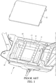
- An electric vehicle 1 is often provided with a receiving space 12 under a tread board 11 that is arranged for supporting user's feet to rest thereon. As shown in FIG 1 , the receiving space 12 receives and holds therein a battery 13 that supplies electrical power source to the electric vehicle 1.
- the battery 13 is received and held in a battery box 14.
- the battery 13 exhibits certain weight and size.
- the electric vehicle 1 must has a predetermined height above the ground so that the battery 13, together with the battery box 14, is generally arranged in a lying condition in the receiving space 12 under the tread board 11.
- a reinforcement member 15 is provided between the tread board 11 and the receiving space 12.
- the known battery box 14 as described above, is effective in receiving and holding the battery 13 therein.
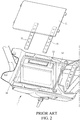
- the user has to remove the tread board 11 and the reinforcement member 15 first and then, the battery box 14 that is in a lying condition must be erected.
- the battery box 14 must be lifted to a condition of being generally perpendicular to the receiving space 12, and then, the user is allowed to lift and remove the battery 13 located in the battery box 14.
- the primary objective of the present invention is to provide a battery box structure of an electric vehicle, which helps overcome the drawback of inconvenience of lifting and removing a battery from a battery box of an electric vehicle.
- the primary technical solution of the present invention as proposed in claim 1 is to provide a battery box structure of an electric vehicle, wherein the electric vehicle at least comprises a frame unit and a vehicle body cover unit; the frame unit comprises tread tubes extending toward a rear side of a vehicle body, the tread tubes being arranged in a left and right pairwise form as a left tread tube and a right tread tube; the vehicle body cover unit at least comprises a tread board that shields the left tread tube and the right tread tube; a battery box is shaft-supported on the frame unit to receive and hold a battery, wherein the battery box has two sides that are provided with support shafts, and the battery box are shaft-supported on the frame unit by the support shafts in a vehicle body left-right direction, so that the battery box is rotatable about a rotation center defined by the support shafts in a vehicle body front-rear direction to an open position or a storage position.
- the battery box is rotatable about a rotation center defined by the support shafts, in the vehicle body front-rear direction, to a open position or a storage position to thereby facilitate lifting and removal of the battery from the battery box.
- the present invention provides a battery box structure of an electric vehicle.
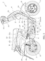
- a frame unit 21 of the electric vehicle 2 is provided, at a front side, with a head tube 22.
- the head tube 22 is provided, at an upper side thereof, with a steering mechanism 221.
- the steering mechanism 221 is connected, at a lower side thereof, to a front fork unit (front shock absorber) 23.
- the front fork unit 23 is provided, at a lower side thereof and in a rotatable manner, with a front wheel 24.
- the frame unit 21 is provided with a main tube 211 extending from the head tube 22 in a direction toward a rear side of a vehicle body.
- the main tube 211 is provided, as being further extended toward the rear side of the vehicle body, with tread tubes.
- the tread tubes are arranged pairwise in a left-right direction as a left tread tube 212 and a right tread tube 213.
- the left tread tube 212 and the right tread tube 213 are provided with rear frames 214 that are arranged pairwise in the left-right direction and extend toward the rear side of the vehicle body.
- the rear frames 214 comprise a rise section 2141 and a side frame section 2142.
- a transverse tube 2141a is arranged between the rise sections 2141.
- a rear wheel 25 is arranged rearward of and under the rear frames 214.
- a driving motor 3 is arranged at one side of the rear wheel 25 such that the driving motor 3 is operable to drive the rear wheel 25 in order to cause the electric vehicle 2 to more forward.
- a seat section 26 that is located above the rear wheel 25 is arranged rearward of the steering mechanism 221 such that a spacing distance is provided between the seat section 26 and the steering mechanism 221.
- the electric vehicle 2 is provided, on an outside thereof, with a vehicle body cover unit 27.
- the vehicle body cover unit 27 comprises a head cover 271 housing the steering mechanism 221, a front head cover 272 arranged at a lower side of the head cover 271 and housing a front end of the vehicle body, and a knee-shielding cover 273 arranged at a rear side of the front head cover 272.
- a tread board 274 is arranged between the steering mechanism 221 and the seat section 26 at a lower side thereof.
- a bottom cover 275 is arranged at a lower side of the tread board 274.
- the electric vehicle 2 is provided, on two sides thereof, with side vehicle body covers 276 at a lower side of the seat section 26.
- a central vehicle body cover 277 is provided in front of and at a lower side of the seat section 26.
- An article storage box 28 is provided at a lower side of the seat section 26 and an upper side of the article storage box 28 is shielded by the seat section 26.
- the electric vehicle 2 is provided with a power source, of which an example that is shown in the drawings includes a driving motor 3 driving the rear wheel 25.
- the electric vehicle 2 of the present invention can alternatively provided with a frontward-arranged motor that drives, by means of a chain or a belt, the rear wheel 25, or a driving mechanism that is made up of a motor and a transmission box to drive the rear wheel 25. It is noted here that the present invention is not limited to the specific way of driving the rear wheel 25 with the driving motor 3.
- the tread board 274 forms a foot support section 29, and the foot support section 29 functions to receive a rider's feet to place thereon.
- the tread board 274 comprises a central tread board 2741 and a peripheral tread board 2742 surrounding the central tread board 2741.
- the bottom cover 275 comprises a central bottom cover 2751 and a peripheral bottom cover 2752 surrounding the central bottom cover 2751.
- the tread board 274 and the bottom cover 275, and also the left tread tube 212 and the right tread tube 213, define a receiving space A.
- the receiving space A receives and holds therein a battery 4.
- the battery 4 is electrically connected with the driving motor 3, in order to provide electrical power to the driving motor 3 to drive the rear wheel 25 to rotate.
- a control device (not shown in the drawings) provided on the steering mechanism 221 can be operated to activate the driving motor 3 to drive the rear wheel 25 to rotate so as to cause the electric vehicle 2 to move.
- the battery 4 is received in a battery box 5.
- the battery box 5 is received in a receiving space A defined by the left tread tube 212 and the right tread tube 213 in a manner of being arranged in a vehicle body front-rear direction of the electric vehicle 2.
- the left tread tube 212 is provided with a left shaft support section 2121
- the right tread tube 213 is provided with a right shaft support section 2131.
- the battery box 5 is provided, on two opposite sides thereof, with support shafts 51 that are extended outward in a vehicle body left-right direction.
- the support shafts 51 that are arranged on the two sides of the battery box 5 are arranged above a battery box center axis 5a of the battery box 5 that extends in the vehicle body front-rear direction.
- the battery box 5 is supported by the support shafts 51, in a manner of being shaft-supported by shafts in the vehicle body left-right direction, on the left shaft support section 2121 of the left tread tube 212 and the right shaft support section 2131 of the right tread tube 213.
- An upper surface of the battery box 5 is fixed to the central tread board 2741, and a lower surface of the battery box 5 is fixed to the central bottom cover 2751.
- One side of the battery box 5 is provided with an opening device 6.
- the opening device 6 comprises a power unit 61 and a driven element 62 that can be driven by the power unit 61.
- the power unit 61 is fixed to a mounting brace 2132 extended downward from the right tread tube 213.
- the power unit 61 comprises a power motor section 611 and a transmission section 612.
- the driven element 62 comprises a toothed member, or more precisely, a curved toothed rack.
- the driven element 62 is mounted to one side of the battery box 5, which is the right side shown in the drawings as an example for illustration.
- the driven element 62 is set in engagement with the transmission section 612 of the power unit 61.
- An electrical power source of the opening device 6 is supplied with a second battery 42 arranged at a lower side of a front portion of the article storage box 28.
- the steering mechanism 221 is provided with a control button (not shown in the drawings) that controls operation of the opening device 6.
- the control button can be actuated to put the opening device 6 into operation for causing the battery box 5 to rotate, about a rotation center defined by the support shafts 51, in a manner of facing toward the vehicle body front-rear direction, to an open position or a storage position in order to be opened in a condition of generally defining a right angle with respect to ground surface, thereby allowing a user to withdraw or remove the battery 4 from the battery box 5.
- the opening device 6 can be arranged at the left side or the right side of the battery box 5, and in other words, the opening device 6 can be arranged on the left tread tube 212 or the right tread tube 213. Being arranged on the right tread tube 213 as shown in the instant embodiment is taken as an example for illustration; however, this invention is not limited to such an embodiment.
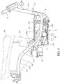
- the battery box 5 is stored, in a manner of being shaft-supported, in the receiving space A under the foot support section 29, wherein at least a portion of a rear end of the battery box 5 is extended further toward the rear side of the vehicle body of the electric vehicle 2 than an orthographic projection of a front end of the seat section 26 so that the storage of the battery box 5 can be achieved with better utilization of the space of the electric vehicle 2 thereby allowing the battery box 5 and the battery 4 received and held in the battery box 5 to be enlarged.
- the battery box 5 is stored, in a manner of being shaft-supported, in the receiving space A under the foot support section 29, wherein at least a portion of a rear end of the battery box 5 is extended further toward the rear side of the vehicle body of the electric vehicle 2 than the central vehicle body cover 277 so that the storage of the battery box 5 can be achieved with better utilization of the space of the electric vehicle 2 thereby allowing the battery box 5 and the battery 4 received and held in the battery box 5 to be enlarged.
- the battery box 5 is stored, in a manner of being shaft-supported, in the receiving space A under the foot support section 29, wherein, as viewed from top, at least a portion of a rear end of the battery box 5 overlaps the transverse tube 2141a, so that the storage of the battery box 5 can be achieved with better utilization of the space of the electric vehicle 2 thereby allowing the battery box 5 and the battery 4 received and held in the battery box 5 to be enlarged.
- the battery box 5 is stored, in a manner of being shaft-supported, in the receiving space A under the foot support section 29, wherein when the battery box 5 is being opened by the opening device 6, a front end of the battery box 6 is moved from a front side of the vehicle body toward the rear side of the vehicle body, and a rear end of the battery box 5 is moved from the rear side of the vehicle body toward the front side of the vehicle body, and the central tread board 2741 that is fixed to the upper surface of the battery box 5 and the central bottom cover 2751 that is fixed to the lower surface of the battery box 5 are opened in synchronization with the battery box 5, and finally, the battery box 5 reaches an opened condition as being generally at a right angle with respect to the ground surface.
- the rear end (lower end) of the battery box 5 projects beyond a lower edge of the peripheral bottom cover 2752 in a direction toward the ground surface, so that the user may withdraw or remove the battery 4 from the battery box 5, effectively avoiding interference of the battery box 5 as being enlarged with other components, thereby effectively enhancing the utilization of the battery box 5.
- the battery box 5 further can be arranged, in a manner of being shaft-supported leftward and rightward, on the side frame sections 2142 of the left and right pairwise rear frames 214 of the frame unit 21.
- the battery box 5 is shaft-supported in the article storage box 28, so that the space of the electric vehicle 2 can be better utilized and the battery 4 that is received in the battery box 5 is provided with feature of shielding.
- the rise sections 2141 of the left and right pairwise the rear frames 214 of the frame unit 21 are provided with a support frame 2143 projecting toward the rear side of the vehicle body.
- the support frame 2143 is provided to allow the battery box 5 to arrange in a manner of being shaft-supported leftward and rightward, and the second battery 41 that supplies electrical power source to the opening device 6 is stored in the foot support section 29, so that the space of the electric vehicle 2 can be better utilized and the battery 4 that is received in the battery box 5 is provided with feature of shielding.
- the head tube 22 of the frame unit 21 is provided, on a front side thereof, with a mounting frame 222.
- the mounting frame 222 allows the battery box 5 to arrange in a manner of being shaft-supported leftward and rightward, so that the space of the electric vehicle 2 can be better utilized and the battery 4 that is received in the battery box 5 is provided with feature of shielding.
- the primary efficacy of the present invention is that two sides of the battery box 5 are provided with the support shafts 51 and the battery box 5 is supported by the support shafts 51, in a manner of being shaft-supported in the vehicle body left-right direction, on the frame unit 21, so that the battery box 5 is rotatable about a rotation center defined by the support shafts 51, in the vehicle body front-rear direction, to a open position or a storage position to thereby facilitate lifting and removal of the battery 4 from the battery box 5.
- the second efficacy of the present invention is that an opening device 6 is arranged at one side of the battery box 5 and the opening device 6 comprises a power unit 61 and a driven element 62 that can be driven by the power unit 61; the power unit 61is arranged on the right tread tube 213 and the driven element 62 is arranged on one side of a circumference of the battery box 5, so that the installation of the opening device 6 is made easy.
- the third efficacy of the present invention is that the power unit 61 comprises a power motor section 611 and a transmission section 612, and the driven element 62 is in engagement with the transmission section 612, so that effects of opening and storage of the opening device 6 are ensured.
- the fourth efficacy of the present invention is that the driven element 62 comprises a curved toothed rack, so that reliability of the operation of the opening device 6 is enhanced.
- the fifth efficacy of the present invention is that the left tread tube 212 is provided with the left shaft support section 2121 and the right tread tube 213 is provided with the right shaft support section 2131, and the left shaft support section 2121 and the right shaft support section 2131 allow the support shafts 51 of the battery box 5 to be supported so that rotatable arrangement of the battery box 5 is made easy.
- the sixth efficacy of the present invention is that the support shafts 51 of the battery box 5 are located above the battery box center axis 5a of the battery box 5 in the vehicle body front-rear direction so that opening and storage of the battery box 5 are made easy.
- the seventh efficacy of the present invention is that the electrical power supply to the opening device 6 is made with a second battery 41 so that the stability of electrical power supply of the opening device 6 can be ensured.
- the eighth efficacy of the present invention is that the vehicle body cover unit 27 further comprises the bottom cover 275 arranged at a lower side of the tread board 274 and when the battery box 5 is received in the receiving space A defined by the left tread tube 212, the right tread tube 213, the tread board 274 and the bottom cover 275, at least a portion of the rear end of the battery box 5 is extended further toward the rear side of the vehicle body than an orthographic projection of a front end of the seat section 26 so that interference of an enlarged battery box 5 with other components can be avoided and thereby enhance the utilization of the battery box 5.
- the ninth efficacy of the present invention is that the rise sections 2141 of the frame unit 21 are provided with a transverse tube 2141a; the vehicle body cover unit 27 further comprises the bottom cover 275 at a lower side of the tread board 274; when the battery box 5 is received and stored in the receiving space A defined by the left tread tube 212, the right tread tube 213, the tread board 274 and the bottom cover 275, as viewed from the top, at least a portion of the rear end of the battery box 5 overlaps the transverse tube 2141a so that interference of an enlarged battery box 5 with other components can be avoided and thereby enhance the utilization of the battery box 5.
- the tenth efficacy of the present invention is that the central vehicle body cover 277 is arranged at a lower side of a front end of the seat section 26 and when the battery box 5 is received and stored in the receiving space A defined by the left tread tube 212, the right tread tube 213, the tread board 274 and the bottom cover 275, at least a portion of the rear end of the battery box 5 is extended further toward the rear side of the vehicle body than the central vehicle body cover 277, so that interference of an enlarged battery box 5 with other components can be avoided and thereby enhance the utilization of the battery box 5.
- the vehicle body cover unit 27 further comprises the bottom cover 275 at a lower side of the tread board 274 and the tread board 274 comprises a central tread board 2741 and a peripheral tread board 2742; the bottom cover 275 comprises a central bottom cover 2751 and a peripheral bottom cover 2752; the central tread board 2741 is fixed to an upper surface of the battery box 5 and the central bottom cover 2751 is fixed to a lower surface of the battery box 5; the central tread board 2741 on the upper surface of the battery box 5 and the central bottom cover 2751 fixed to the lower surface of the battery box 5 are opened in synchronization with the battery box 5 and thus, when the battery box 5 is opened in a condition of being generally at a right angle with respect to the ground surface, the rear end of the battery box 5 projects beyond a lower edge of the peripheral bottom cover 2572 in a direction toward the ground surface, so that withdrawal of the battery 4 from the battery box 5 by a user can be facilitated and at the same time, interference of an enlarged battery box 5 with
- the twelfth efficacy of the present invention is that an article storage box 28 is provided on the side frame sections 2142 of the frame unit 21 and the battery box 5 is shaft-supported on the side frame section 2142 of the frame unit 21, in a manner of being shaft-supported in the vehicle body left-right direction, and is received in the article storage box 28, so that the space of the electric vehicle 2 can be fully used and the battery 4 received in the battery box 5 is provided with a feature of shielding.
- the thirteenth efficacy of the present invention is that the left tread tube 212, the right tread tube 213, the tread board 274 and the bottom cover 275 define a receiving space A, and the receiving space A receives and holds the battery box 5 therein, so that the space of the electric vehicle 2 can be fully used and the battery 4 received in the battery box 5 is provided with a feature of shielding.
- the fourteenth efficacy of the present invention is that the rise sections 2141 of the frame unit 21 are provided with a support frame 2143 projecting toward the rear side of the vehicle body and the battery box 5 is shaft-supported on the support frame 2143, in a manner of being shaft-supported in the vehicle body left-right direction, so that the space of the electric vehicle 2 can be fully used and the battery 4 received in the battery box 5 is provided with a feature of shielding.
- the fifteenth efficacy of the present invention is that the head tube 22 of the frame unit 21 is provided with a mounting frame 222 projecting toward the front side of the vehicle body and the battery box 5 is shaft-supported on the mounting frame 222, in a manner of being shaft-supported in the vehicle body left-right direction, so that the space of the electric vehicle 2 can be fully used and the battery 4 received in the battery box 5 is provided with a feature of shielding.
Landscapes
- Engineering & Computer Science (AREA)
- Mechanical Engineering (AREA)
- Chemical & Material Sciences (AREA)
- Transportation (AREA)
- General Chemical & Material Sciences (AREA)
- Electrochemistry (AREA)
- Chemical Kinetics & Catalysis (AREA)
- Combustion & Propulsion (AREA)
- Power Engineering (AREA)
- Life Sciences & Earth Sciences (AREA)
- Sustainable Energy (AREA)
- Sustainable Development (AREA)
- Aviation & Aerospace Engineering (AREA)
- Arrangement Or Mounting Of Propulsion Units For Vehicles (AREA)
- Battery Mounting, Suspending (AREA)
- Automatic Cycles, And Cycles In General (AREA)
- Electric Propulsion And Braking For Vehicles (AREA)
Abstract
Description
- The present invention generally relates to a battery box structure of an electric vehicle, and more particularly to a battery box structure of an electric vehicle that eases lifting and removal of the battery from the electric vehicle and allows enlargement of the battery box and the battery.
- An
electric vehicle 1 is often provided with areceiving space 12 under atread board 11 that is arranged for supporting user's feet to rest thereon. As shown inFIG 1 , thereceiving space 12 receives and holds therein abattery 13 that supplies electrical power source to theelectric vehicle 1. - As shown in
FIGS. 1 and2 , thebattery 13 is received and held in abattery box 14. Thebattery 13 exhibits certain weight and size. In addition, theelectric vehicle 1 must has a predetermined height above the ground so that thebattery 13, together with thebattery box 14, is generally arranged in a lying condition in thereceiving space 12 under thetread board 11. In order to provide thetread board 11 with a desired structural strength to support the user's feet resting thereon, areinforcement member 15 is provided between thetread board 11 and thereceiving space 12. Thus, with the arrangement of thereinforcement member 15, the structural strength of thetread board 11 is improved. - The known
battery box 14 as described above, is effective in receiving and holding thebattery 13 therein. When service, replacement, or withdrawal for re-charging of thebattery 13 become necessary, the user has to remove thetread board 11 and thereinforcement member 15 first and then, thebattery box 14 that is in a lying condition must be erected. In other words, thebattery box 14 must be lifted to a condition of being generally perpendicular to thereceiving space 12, and then, the user is allowed to lift and remove thebattery 13 located in thebattery box 14. Such a operation of first removing thetread board 11 and thereinforcement member 15 and then erecting thebattery box 14 in order to lift and remove thebattery 13 suffers, on the one hand, the engineering complexity of removing thetread board 11 and thereinforcement member 15, and, on the other hand, severe hindrance caused by an extremely small gap between thereceiving space 12 and an outer circumference of thebattery box 14. In addition, since thebattery 13 located in thebattery box 14 is of quite a weight, the operation of erecting thebattery box 14 is generally difficult. - Thus, it is a challenge of the electric vehicle industry to provide a battery box structure of an electric vehicle that helps lift and remove a battery from an electric vehicle.
- The primary objective of the present invention is to provide a battery box structure of an electric vehicle, which helps overcome the drawback of inconvenience of lifting and removing a battery from a battery box of an electric vehicle.
- For such a purpose, the primary technical solution of the present invention as proposed in
claim 1 is to provide a battery box structure of an electric vehicle, wherein the electric vehicle at least comprises a frame unit and a vehicle body cover unit; the frame unit comprises tread tubes extending toward a rear side of a vehicle body, the tread tubes being arranged in a left and right pairwise form as a left tread tube and a right tread tube; the vehicle body cover unit at least comprises a tread board that shields the left tread tube and the right tread tube; a battery box is shaft-supported on the frame unit to receive and hold a battery, wherein the battery box has two sides that are provided with support shafts, and the battery box are shaft-supported on the frame unit by the support shafts in a vehicle body left-right direction, so that the battery box is rotatable about a rotation center defined by the support shafts in a vehicle body front-rear direction to an open position or a storage position. - The efficacy that the primary technical solution of the present invention proposed in
claim 1 is that the battery box is rotatable about a rotation center defined by the support shafts, in the vehicle body front-rear direction, to a open position or a storage position to thereby facilitate lifting and removal of the battery from the battery box. -
-
FIG. 1 is a schematic view illustrating a conventional electric vehicle battery box. -
FIG. 2 is a schematic view illustrating withdrawal of the conventional electric vehicle battery box. -
FIG. 3 is a side elevational view illustrating an electric vehicle according to the present invention. -
FIG. 4 is a schematic view illustrating an arrangement of a battery box of the electric vehicle according to the present invention. -
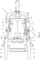
FIG. 5 is a top plan view illustrating the arrangement of the battery box of the electric vehicle according to the present invention. -
FIG. 6 is a schematic view illustrating a tread board of the electric vehicle according to the present invention. -
FIG. 7 is a schematic view illustrating a bottom cover of the electric vehicle according to the present invention. -
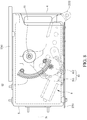
FIG. 8 is a schematic view illustrating the battery box and an opening device according to the present invention. -
FIG. 9 is a schematic view illustrating an operation ofFIG. 8 . -
FIG. 10 is a schematic view illustrating opening of the battery box the electric vehicle according to the present invention. -
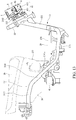
FIG. 11 shows another embodiment of the arrangement of the battery box of the electric vehicle according to the present invention. -
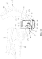
FIG. 12 shows a further embodiment of the arrangement of the battery box of the electric vehicle according to the present invention. -
FIG. 13 shows yet a further embodiment of the arrangement of the battery box of the electric vehicle according to the present invention. - Firstly, referring to
FIGS. 3 ,4 ,6 , and7 , the present invention provides a battery box structure of an electric vehicle. Aframe unit 21 of theelectric vehicle 2 is provided, at a front side, with ahead tube 22. Thehead tube 22 is provided, at an upper side thereof, with asteering mechanism 221. Thesteering mechanism 221 is connected, at a lower side thereof, to a front fork unit (front shock absorber) 23. Thefront fork unit 23 is provided, at a lower side thereof and in a rotatable manner, with afront wheel 24. Theframe unit 21 is provided with amain tube 211 extending from thehead tube 22 in a direction toward a rear side of a vehicle body. Themain tube 211 is provided, as being further extended toward the rear side of the vehicle body, with tread tubes. The tread tubes are arranged pairwise in a left-right direction as aleft tread tube 212 and aright tread tube 213. Theleft tread tube 212 and theright tread tube 213 are provided withrear frames 214 that are arranged pairwise in the left-right direction and extend toward the rear side of the vehicle body. Therear frames 214 comprise arise section 2141 and aside frame section 2142. Atransverse tube 2141a is arranged between therise sections 2141. Arear wheel 25 is arranged rearward of and under therear frames 214. A drivingmotor 3 is arranged at one side of therear wheel 25 such that the drivingmotor 3 is operable to drive therear wheel 25 in order to cause theelectric vehicle 2 to more forward. Aseat section 26 that is located above therear wheel 25 is arranged rearward of thesteering mechanism 221 such that a spacing distance is provided between theseat section 26 and thesteering mechanism 221. Theelectric vehicle 2 is provided, on an outside thereof, with a vehiclebody cover unit 27. The vehiclebody cover unit 27 comprises ahead cover 271 housing thesteering mechanism 221, afront head cover 272 arranged at a lower side of thehead cover 271 and housing a front end of the vehicle body, and a knee-shielding cover 273 arranged at a rear side of thefront head cover 272. Atread board 274 is arranged between thesteering mechanism 221 and theseat section 26 at a lower side thereof. Abottom cover 275 is arranged at a lower side of thetread board 274. Theelectric vehicle 2 is provided, on two sides thereof, with side vehicle body covers 276 at a lower side of theseat section 26. A centralvehicle body cover 277 is provided in front of and at a lower side of theseat section 26. Anarticle storage box 28 is provided at a lower side of theseat section 26 and an upper side of thearticle storage box 28 is shielded by theseat section 26. Theelectric vehicle 2 is provided with a power source, of which an example that is shown in the drawings includes a drivingmotor 3 driving therear wheel 25. In practice, theelectric vehicle 2 of the present invention can alternatively provided with a frontward-arranged motor that drives, by means of a chain or a belt, therear wheel 25, or a driving mechanism that is made up of a motor and a transmission box to drive therear wheel 25. It is noted here that the present invention is not limited to the specific way of driving therear wheel 25 with thedriving motor 3. - As shown in
FIGS. 3 ,4 ,5 ,6 , and7 , thetread board 274 forms afoot support section 29, and thefoot support section 29 functions to receive a rider's feet to place thereon. Thetread board 274 comprises acentral tread board 2741 and aperipheral tread board 2742 surrounding thecentral tread board 2741. Thebottom cover 275 comprises acentral bottom cover 2751 and aperipheral bottom cover 2752 surrounding thecentral bottom cover 2751. Thetread board 274 and thebottom cover 275, and also theleft tread tube 212 and theright tread tube 213, define a receiving space A. The receiving space A receives and holds therein abattery 4. Thebattery 4 is electrically connected with thedriving motor 3, in order to provide electrical power to the drivingmotor 3 to drive therear wheel 25 to rotate. As such, a control device (not shown in the drawings) provided on thesteering mechanism 221 can be operated to activate the drivingmotor 3 to drive therear wheel 25 to rotate so as to cause theelectric vehicle 2 to move. - As shown in
FIGS. 3 ,4 ,5 ,6 ,7 , and8 , thebattery 4 is received in abattery box 5. Thebattery box 5 is received in a receiving space A defined by theleft tread tube 212 and theright tread tube 213 in a manner of being arranged in a vehicle body front-rear direction of theelectric vehicle 2. Theleft tread tube 212 is provided with a leftshaft support section 2121, and theright tread tube 213 is provided with a rightshaft support section 2131. Speaking more precisely, thebattery box 5 is provided, on two opposite sides thereof, withsupport shafts 51 that are extended outward in a vehicle body left-right direction. Thesupport shafts 51 that are arranged on the two sides of thebattery box 5 are arranged above a batterybox center axis 5a of thebattery box 5 that extends in the vehicle body front-rear direction. As such, thebattery box 5 is supported by thesupport shafts 51, in a manner of being shaft-supported by shafts in the vehicle body left-right direction, on the leftshaft support section 2121 of theleft tread tube 212 and the rightshaft support section 2131 of theright tread tube 213. An upper surface of thebattery box 5 is fixed to thecentral tread board 2741, and a lower surface of thebattery box 5 is fixed to thecentral bottom cover 2751. One side of thebattery box 5 is provided with anopening device 6. - As shown in
FIGS. 4 ,5 ,6 ,7 ,8 , and9 , theopening device 6 comprises apower unit 61 and a drivenelement 62 that can be driven by thepower unit 61. Thepower unit 61 is fixed to a mountingbrace 2132 extended downward from theright tread tube 213. Thepower unit 61 comprises apower motor section 611 and atransmission section 612. The drivenelement 62 comprises a toothed member, or more precisely, a curved toothed rack. The drivenelement 62 is mounted to one side of thebattery box 5, which is the right side shown in the drawings as an example for illustration. The drivenelement 62 is set in engagement with thetransmission section 612 of thepower unit 61. An electrical power source of theopening device 6 is supplied with a second battery 42 arranged at a lower side of a front portion of thearticle storage box 28. Thesteering mechanism 221 is provided with a control button (not shown in the drawings) that controls operation of theopening device 6. As such, the control button can be actuated to put theopening device 6 into operation for causing thebattery box 5 to rotate, about a rotation center defined by thesupport shafts 51, in a manner of facing toward the vehicle body front-rear direction, to an open position or a storage position in order to be opened in a condition of generally defining a right angle with respect to ground surface, thereby allowing a user to withdraw or remove thebattery 4 from thebattery box 5. Theopening device 6 can be arranged at the left side or the right side of thebattery box 5, and in other words, theopening device 6 can be arranged on theleft tread tube 212 or theright tread tube 213. Being arranged on theright tread tube 213 as shown in the instant embodiment is taken as an example for illustration; however, this invention is not limited to such an embodiment. - As shown in
FIG. 4 , thebattery box 5 is stored, in a manner of being shaft-supported, in the receiving space A under thefoot support section 29, wherein at least a portion of a rear end of thebattery box 5 is extended further toward the rear side of the vehicle body of theelectric vehicle 2 than an orthographic projection of a front end of theseat section 26 so that the storage of thebattery box 5 can be achieved with better utilization of the space of theelectric vehicle 2 thereby allowing thebattery box 5 and thebattery 4 received and held in thebattery box 5 to be enlarged. - As shown in
FIG. 4 , thebattery box 5 is stored, in a manner of being shaft-supported, in the receiving space A under thefoot support section 29, wherein at least a portion of a rear end of thebattery box 5 is extended further toward the rear side of the vehicle body of theelectric vehicle 2 than the centralvehicle body cover 277 so that the storage of thebattery box 5 can be achieved with better utilization of the space of theelectric vehicle 2 thereby allowing thebattery box 5 and thebattery 4 received and held in thebattery box 5 to be enlarged. - As shown in
FIG. 5 , thebattery box 5 is stored, in a manner of being shaft-supported, in the receiving space A under thefoot support section 29, wherein, as viewed from top, at least a portion of a rear end of thebattery box 5 overlaps thetransverse tube 2141a, so that the storage of thebattery box 5 can be achieved with better utilization of the space of theelectric vehicle 2 thereby allowing thebattery box 5 and thebattery 4 received and held in thebattery box 5 to be enlarged. - As shown in
FIG. 10 , thebattery box 5 is stored, in a manner of being shaft-supported, in the receiving space A under thefoot support section 29, wherein when thebattery box 5 is being opened by theopening device 6, a front end of thebattery box 6 is moved from a front side of the vehicle body toward the rear side of the vehicle body, and a rear end of thebattery box 5 is moved from the rear side of the vehicle body toward the front side of the vehicle body, and thecentral tread board 2741 that is fixed to the upper surface of thebattery box 5 and thecentral bottom cover 2751 that is fixed to the lower surface of thebattery box 5 are opened in synchronization with thebattery box 5, and finally, thebattery box 5 reaches an opened condition as being generally at a right angle with respect to the ground surface. Under this condition, the rear end (lower end) of thebattery box 5 projects beyond a lower edge of theperipheral bottom cover 2752 in a direction toward the ground surface, so that the user may withdraw or remove thebattery 4 from thebattery box 5, effectively avoiding interference of thebattery box 5 as being enlarged with other components, thereby effectively enhancing the utilization of thebattery box 5. - As shown in
FIG. 11 , in putting the present invention into practice, thebattery box 5 further can be arranged, in a manner of being shaft-supported leftward and rightward, on theside frame sections 2142 of the left and right pairwise rear frames 214 of theframe unit 21. Speaking more precisely, thebattery box 5 is shaft-supported in thearticle storage box 28, so that the space of theelectric vehicle 2 can be better utilized and thebattery 4 that is received in thebattery box 5 is provided with feature of shielding. - As shown in
FIG. 12 , in putting the present invention into practice, therise sections 2141 of the left and right pairwise therear frames 214 of theframe unit 21 are provided with asupport frame 2143 projecting toward the rear side of the vehicle body. Thesupport frame 2143 is provided to allow thebattery box 5 to arrange in a manner of being shaft-supported leftward and rightward, and thesecond battery 41 that supplies electrical power source to theopening device 6 is stored in thefoot support section 29, so that the space of theelectric vehicle 2 can be better utilized and thebattery 4 that is received in thebattery box 5 is provided with feature of shielding. - As shown in
FIG. 13 , in putting the present invention into practice, thehead tube 22 of theframe unit 21 is provided, on a front side thereof, with a mountingframe 222. The mountingframe 222 allows thebattery box 5 to arrange in a manner of being shaft-supported leftward and rightward, so that the space of theelectric vehicle 2 can be better utilized and thebattery 4 that is received in thebattery box 5 is provided with feature of shielding. - The primary efficacy of the present invention is that two sides of the
battery box 5 are provided with thesupport shafts 51 and thebattery box 5 is supported by thesupport shafts 51, in a manner of being shaft-supported in the vehicle body left-right direction, on theframe unit 21, so that thebattery box 5 is rotatable about a rotation center defined by thesupport shafts 51, in the vehicle body front-rear direction, to a open position or a storage position to thereby facilitate lifting and removal of thebattery 4 from thebattery box 5. - The second efficacy of the present invention is that an
opening device 6 is arranged at one side of thebattery box 5 and theopening device 6 comprises apower unit 61 and a drivenelement 62 that can be driven by thepower unit 61; the power unit 61is arranged on theright tread tube 213 and the drivenelement 62 is arranged on one side of a circumference of thebattery box 5, so that the installation of theopening device 6 is made easy. - The third efficacy of the present invention is that the
power unit 61 comprises apower motor section 611 and atransmission section 612, and the drivenelement 62 is in engagement with thetransmission section 612, so that effects of opening and storage of theopening device 6 are ensured. - The fourth efficacy of the present invention is that the driven
element 62 comprises a curved toothed rack, so that reliability of the operation of theopening device 6 is enhanced. - The fifth efficacy of the present invention is that the
left tread tube 212 is provided with the leftshaft support section 2121 and theright tread tube 213 is provided with the rightshaft support section 2131, and the leftshaft support section 2121 and the rightshaft support section 2131 allow thesupport shafts 51 of thebattery box 5 to be supported so that rotatable arrangement of thebattery box 5 is made easy. - The sixth efficacy of the present invention is that the
support shafts 51 of thebattery box 5 are located above the batterybox center axis 5a of thebattery box 5 in the vehicle body front-rear direction so that opening and storage of thebattery box 5 are made easy. - The seventh efficacy of the present invention is that the electrical power supply to the
opening device 6 is made with asecond battery 41 so that the stability of electrical power supply of theopening device 6 can be ensured. - The eighth efficacy of the present invention is that the vehicle
body cover unit 27 further comprises thebottom cover 275 arranged at a lower side of thetread board 274 and when thebattery box 5 is received in the receiving space A defined by theleft tread tube 212, theright tread tube 213, thetread board 274 and thebottom cover 275, at least a portion of the rear end of thebattery box 5 is extended further toward the rear side of the vehicle body than an orthographic projection of a front end of theseat section 26 so that interference of anenlarged battery box 5 with other components can be avoided and thereby enhance the utilization of thebattery box 5. - The ninth efficacy of the present invention is that the
rise sections 2141 of theframe unit 21 are provided with atransverse tube 2141a; the vehiclebody cover unit 27 further comprises thebottom cover 275 at a lower side of thetread board 274; when thebattery box 5 is received and stored in the receiving space A defined by theleft tread tube 212, theright tread tube 213, thetread board 274 and thebottom cover 275, as viewed from the top, at least a portion of the rear end of thebattery box 5 overlaps thetransverse tube 2141a so that interference of anenlarged battery box 5 with other components can be avoided and thereby enhance the utilization of thebattery box 5. - The tenth efficacy of the present invention is that the central
vehicle body cover 277 is arranged at a lower side of a front end of theseat section 26 and when thebattery box 5 is received and stored in the receiving space A defined by theleft tread tube 212, theright tread tube 213, thetread board 274 and thebottom cover 275, at least a portion of the rear end of thebattery box 5 is extended further toward the rear side of the vehicle body than the centralvehicle body cover 277, so that interference of anenlarged battery box 5 with other components can be avoided and thereby enhance the utilization of thebattery box 5. - The eleventh efficacy of the present invention is that the vehicle
body cover unit 27 further comprises thebottom cover 275 at a lower side of thetread board 274 and thetread board 274 comprises acentral tread board 2741 and aperipheral tread board 2742; thebottom cover 275 comprises acentral bottom cover 2751 and aperipheral bottom cover 2752; thecentral tread board 2741 is fixed to an upper surface of thebattery box 5 and thecentral bottom cover 2751 is fixed to a lower surface of thebattery box 5; thecentral tread board 2741 on the upper surface of thebattery box 5 and thecentral bottom cover 2751 fixed to the lower surface of thebattery box 5 are opened in synchronization with thebattery box 5 and thus, when thebattery box 5 is opened in a condition of being generally at a right angle with respect to the ground surface, the rear end of thebattery box 5 projects beyond a lower edge of the peripheral bottom cover 2572 in a direction toward the ground surface, so that withdrawal of thebattery 4 from thebattery box 5 by a user can be facilitated and at the same time, interference of anenlarged battery box 5 with other components can be avoided and thereby enhance the utilization of thebattery box 5. - The twelfth efficacy of the present invention is that an
article storage box 28 is provided on theside frame sections 2142 of theframe unit 21 and thebattery box 5 is shaft-supported on theside frame section 2142 of theframe unit 21, in a manner of being shaft-supported in the vehicle body left-right direction, and is received in thearticle storage box 28, so that the space of theelectric vehicle 2 can be fully used and thebattery 4 received in thebattery box 5 is provided with a feature of shielding. - The thirteenth efficacy of the present invention is that the
left tread tube 212, theright tread tube 213, thetread board 274 and thebottom cover 275 define a receiving space A, and the receiving space A receives and holds thebattery box 5 therein, so that the space of theelectric vehicle 2 can be fully used and thebattery 4 received in thebattery box 5 is provided with a feature of shielding. - The fourteenth efficacy of the present invention is that the
rise sections 2141 of theframe unit 21 are provided with asupport frame 2143 projecting toward the rear side of the vehicle body and thebattery box 5 is shaft-supported on thesupport frame 2143, in a manner of being shaft-supported in the vehicle body left-right direction, so that the space of theelectric vehicle 2 can be fully used and thebattery 4 received in thebattery box 5 is provided with a feature of shielding. - The fifteenth efficacy of the present invention is that the
head tube 22 of theframe unit 21 is provided with a mountingframe 222 projecting toward the front side of the vehicle body and thebattery box 5 is shaft-supported on the mountingframe 222, in a manner of being shaft-supported in the vehicle body left-right direction, so that the space of theelectric vehicle 2 can be fully used and thebattery 4 received in thebattery box 5 is provided with a feature of shielding.
Claims (15)
- A battery box structure of an electric vehicle, wherein the electric vehicle (2) at least comprises a frame unit (21) and a vehicle body cover unit (27); the frame unit (21) comprises tread tubes (212, 213) extending toward a rear side of a vehicle body, the tread tubes (212, 213) being arranged in a left and right pairwise form as a left tread tube (212) and a right tread tube (213); the vehicle body cover unit (27) at least comprises a tread board (274) that shields the left tread tube (212) and the right tread tube (213)d; a battery box (5) is shaft-supported on the frame unit (21) to receive and hold a battery (4), characterized in that the battery box (5) has two sides that are provided with support shafts (51), and the battery box (5) are shaft-supported on the frame unit (21) by the support shafts (51) in a vehicle body left-right direction, so that the battery box (5) is rotatable about a rotation center defined by the support shafts (51) in a vehicle body front-rear direction to an open position or a storage position.
- The battery box structure of the electric vehicle according to claim 1, wherein an opening device (6) is arranged at one side of the battery box (5) and the opening device (6) comprises a power unit (61) and a driven element (62) drivable by the power unit (61); and the power unit (61) is arranged on the tread tubes (212, 213) and the driven element (62) is arranged at one side of a circumference of the battery box (5).
- The battery box structure of the electric vehicle according to claim 2, wherein the power unit (61) comprises a power motor section (611) and a transmission section (612), and the driven element (62) is in engagement with the transmission section (612).
- The battery box structure of the electric vehicle according to claim 2 or 3, wherein the driven element (62) comprises a curved toothed rack.
- The battery box structure of the electric vehicle according to claim 1, wherein the left tread tube (212) comprises a left shaft support section (2121) and the right tread tube (213) comprises a left shaft support section (2131), the left shaft support section (2121) and the left shaft support section (2131) shaft-supporting the support shafts (51) of the battery box (5).
- The battery box structure of the electric vehicle according to claim 1 or 5, wherein the support shafts (51) of the battery box (5) are located above a battery box center axis (5a) of the battery box (5) in the vehicle body front-rear direction.
- The battery box structure of the electric vehicle according to claim 2, wherein the opening device (6) has an electrical power source supplied with a second battery (41).
- The battery box structure of the electric vehicle according to claim 1, wherein the frame unit (21) further comprises a seat section (26); the vehicle body cover unit (27) further comprises a bottom cover (275) at a lower side of the tread board (274); the battery box (5) is received in a receiving space (A) defined by the left tread tube (212), the right tread tube (213), the tread board (274) and the bottom cover (275) and at least a portion of a rear end of the battery box (5) extending further toward the rear side of the vehicle body than an orthographic projection of a front end of the seat section (26).
- The battery box structure of the electric vehicle according to claim 1, wherein the frame unit (21) further comprises a rise section (2141), the rise section (2141) being provided with a transverse tube (2141a); the vehicle body cover unit (27) further comprises a bottom cover (275) arranged at a lower side of the tread board (274); the battery box (5) is received in a receiving space (A) defined by the left tread tube (212), the right tread tube (213), the tread board (274) and the bottom cover (275) and when viewed from the top, at least a portion of a rear end of the battery box (5) overlaps the transverse tube (2141a).
- The battery box structure of the electric vehicle according to claim 1 or 8, wherein the frame unit (21) comprises a seat section (26), and the vehicle body cover unit (27) comprises a central vehicle body cover (277); the central vehicle body cover (277) is arranged at a lower side of a front end of the seat section (26), the battery box (5) being received ion a receiving space (A) defined by the left tread tube (212), the right tread tube (213), the tread board (274) and the bottom cover (275), at least a portion of a rear end of the battery box (5) extending further toward the rear side of the vehicle body than the central vehicle body cover (277).
- The battery box structure of the electric vehicle according to claim 1, 8, or 9, wherein the vehicle body cover unit (27) further comprises a bottom cover (275) arranged at a lower side of the tread board (274); the tread board (274) comprises a central tread board (2741) and a peripheral tread board (2742); the bottom cover (275) comprises a central bottom cover (2751) and a peripheral bottom cover (2752); the central tread board (2741) is fixed to an upper surface of the battery box (5) and the central bottom cover (2751) is fixed to a lower surface of the battery box (5); the central tread board (2741) on the upper surface of the battery box (5) and the central bottom cover (2751) fixed to the lower surface of the battery box (5) are openable in synchronization with the battery box (5), so that when the battery box (5) is opened to a condition of being generally at a right angle with respect to a ground surface, the rear end of the battery box (5) projects beyond a lower edge of the peripheral bottom cover (2752) in a direction toward the ground surface.
- The battery box structure of the electric vehicle according to claim 1, wherein the frame unit (21) comprises side frame sections (2142) arranged in a left and right pairwise form, an article storage box (28) being provided on the side frame sections (2142) of the frame unit (21), the battery box (5) being shaft-supported on the side frame sections (2142) of the frame unit (21) in a manner of being shaft-supported in the vehicle body left-right direction, and is received in the article storage box (28).
- The battery box structure of the electric vehicle according to claim 1, wherein the left tread tube (212), the right tread tube (213), the tread board (274) and the bottom cover (275) define a receiving space (A), and the receiving space (A) receives the battery box (5) therein.
- The battery box structure of the electric vehicle according to claim 1, wherein the frame unit (21) further comprises a rise section (2141), the rise section (2141) of the frame unit (21) being provided with a support frame (2143) projecting toward the rear side of the vehicle body, the battery box (5) being shaft-supported on the support frame (2143) in a manner of being shaft-supported in the vehicle body left-right direction.
- The battery box structure of the electric vehicle according to claim 1, wherein the frame unit (21) further comprises a head tube (22), the head tube (22) of the frame unit (21) being provided with a mounting frame (222) projecting toward a front side of the vehicle body, the battery box (5) being shaft-supported on the mounting frame (222) in a manner of being shaft-supported in the vehicle body left-right direction.
Applications Claiming Priority (1)
| Application Number | Priority Date | Filing Date | Title |
|---|---|---|---|
| TW107103523A TWI653179B (en) | 2018-01-31 | 2018-01-31 | Battery box structure of electric vehicle |
Publications (1)
| Publication Number | Publication Date |
|---|---|
| EP3521080A1 true EP3521080A1 (en) | 2019-08-07 |
Family
ID=66590976
Family Applications (1)
| Application Number | Title | Priority Date | Filing Date |
|---|---|---|---|
| EP19151738.2A Withdrawn EP3521080A1 (en) | 2018-01-31 | 2019-01-15 | Battery box structure of electric vehicle |
Country Status (7)
| Country | Link |
|---|---|
| US (1) | US10668827B2 (en) |
| EP (1) | EP3521080A1 (en) |
| JP (1) | JP2019131166A (en) |
| CN (1) | CN110104106A (en) |
| CA (1) | CA3030004A1 (en) |
| PH (1) | PH12019050002A1 (en) |
| TW (1) | TWI653179B (en) |
Families Citing this family (6)
| Publication number | Priority date | Publication date | Assignee | Title |
|---|---|---|---|---|
| JP6880340B2 (en) * | 2018-10-22 | 2021-06-02 | 本田技研工業株式会社 | Mobile |
| CN217672182U (en) * | 2019-09-27 | 2022-10-28 | 本田技研工业株式会社 | Charger for mobile storage battery |
| US12218371B2 (en) | 2019-10-11 | 2025-02-04 | Honda Motor Co., Ltd. | Battery housing apparatus and electric vehicle |
| JP7367496B2 (en) * | 2019-11-29 | 2023-10-24 | スズキ株式会社 | saddle type vehicle |
| IN202141005004A (en) * | 2021-02-05 | 2021-02-12 | Oben Electric Vehicles Private Limited | |
| CN116176748A (en) * | 2023-01-13 | 2023-05-30 | 深圳作为科技有限公司 | A pedal structure and scooter |
Citations (6)
| Publication number | Priority date | Publication date | Assignee | Title |
|---|---|---|---|---|
| EP0741060A2 (en) * | 1995-05-01 | 1996-11-06 | Yamaha Hatsudoki Kabushiki Kaisha | Battery powered motor scooter and battery exchange device |
| EP1215111A1 (en) * | 1999-03-01 | 2002-06-19 | TOKYO R & D Co., Ltd. | Electric vehicle |
| JP2013209054A (en) * | 2012-03-30 | 2013-10-10 | Honda Motor Co Ltd | Electric saddle type vehicle |
| JP2015069823A (en) * | 2013-09-27 | 2015-04-13 | 本田技研工業株式会社 | Battery attachment structure for electric vehicles |
| WO2017038247A1 (en) * | 2015-08-31 | 2017-03-09 | 本田技研工業株式会社 | Battery case structure for electric-powered vehicles, and electric-powered vehicle |
| TWI584999B (en) * | 2016-11-15 | 2017-06-01 | 光陽工業股份有限公司 | Electric two-wheeled vehicle battery box opening structure |
Family Cites Families (10)
| Publication number | Priority date | Publication date | Assignee | Title |
|---|---|---|---|---|
| JPH07298410A (en) * | 1994-04-28 | 1995-11-10 | Kubota Corp | Power source structure of electric cart |
| DE69628637T2 (en) * | 1995-09-18 | 2004-04-29 | Seiko Epson Corp. | SECURITY MECHANISM FOR AN ELECTRIC VEHICLE |
| JP2008080841A (en) * | 2006-09-26 | 2008-04-10 | Toyota Auto Body Co Ltd | Rechargeable battery mounting structure |
| JP2009220615A (en) * | 2008-03-13 | 2009-10-01 | Honda Motor Co Ltd | Screen device of motorcycle |
| CN103373409B (en) * | 2012-04-27 | 2016-03-02 | 深圳市台铃电动车有限公司 | Electronic pair of support arrangement |
| EP2978659B1 (en) * | 2013-03-28 | 2018-10-03 | Hartmobile B.V. | Motor scooter |
| US10647371B2 (en) * | 2015-09-25 | 2020-05-12 | Honda Motor Co., Ltd. | Handle lock structure for saddled vehicle |
| TWM533592U (en) * | 2016-09-05 | 2016-12-11 | Kwang Yang Motor Co | Battery box structure of electric two-wheeled vehicle |
| CN206218100U (en) * | 2016-09-29 | 2017-06-06 | 光阳工业股份有限公司 | Electric two-wheel vehicle battery box structure |
| TWI653180B (en) * | 2018-01-31 | 2019-03-11 | 光陽工業股份有限公司 | Battery box structure of electric vehicle |
-
2018
- 2018-01-31 TW TW107103523A patent/TWI653179B/en active
- 2018-09-12 CN CN201811062652.2A patent/CN110104106A/en active Pending
-
2019
- 2019-01-15 EP EP19151738.2A patent/EP3521080A1/en not_active Withdrawn
- 2019-01-15 CA CA3030004A patent/CA3030004A1/en not_active Abandoned
- 2019-01-15 US US16/247,577 patent/US10668827B2/en not_active Expired - Fee Related
- 2019-01-15 PH PH12019050002A patent/PH12019050002A1/en unknown
- 2019-01-15 JP JP2019004176A patent/JP2019131166A/en active Pending
Patent Citations (6)
| Publication number | Priority date | Publication date | Assignee | Title |
|---|---|---|---|---|
| EP0741060A2 (en) * | 1995-05-01 | 1996-11-06 | Yamaha Hatsudoki Kabushiki Kaisha | Battery powered motor scooter and battery exchange device |
| EP1215111A1 (en) * | 1999-03-01 | 2002-06-19 | TOKYO R & D Co., Ltd. | Electric vehicle |
| JP2013209054A (en) * | 2012-03-30 | 2013-10-10 | Honda Motor Co Ltd | Electric saddle type vehicle |
| JP2015069823A (en) * | 2013-09-27 | 2015-04-13 | 本田技研工業株式会社 | Battery attachment structure for electric vehicles |
| WO2017038247A1 (en) * | 2015-08-31 | 2017-03-09 | 本田技研工業株式会社 | Battery case structure for electric-powered vehicles, and electric-powered vehicle |
| TWI584999B (en) * | 2016-11-15 | 2017-06-01 | 光陽工業股份有限公司 | Electric two-wheeled vehicle battery box opening structure |
Also Published As
| Publication number | Publication date |
|---|---|
| US20190232804A1 (en) | 2019-08-01 |
| JP2019131166A (en) | 2019-08-08 |
| CN110104106A (en) | 2019-08-09 |
| TW201934410A (en) | 2019-09-01 |
| US10668827B2 (en) | 2020-06-02 |
| CA3030004A1 (en) | 2019-07-31 |
| TWI653179B (en) | 2019-03-11 |
| PH12019050002A1 (en) | 2019-08-14 |
Similar Documents
| Publication | Publication Date | Title |
|---|---|---|
| US10668827B2 (en) | Battery box structure of electric vehicle | |
| US10384562B1 (en) | Battery box structure of electric vehicle | |
| EP3521148B1 (en) | Structure of electric vehicle | |
| US10351017B1 (en) | Battery box locking structure of electric vehicle | |
| US9434243B2 (en) | Straddle-type electric vehicle | |
| US10384740B1 (en) | Opening control structure of electric vehicle battery box | |
| EP3290323A1 (en) | Battery box structure of electrical two-wheeled vehicle | |
| US10384563B1 (en) | Protection cover of battery box of electric vehicle | |
| US20130270026A1 (en) | Electric Motorcycle | |
| US10071782B2 (en) | Electric vehicle | |
| JP7649245B2 (en) | Battery storage device and electric vehicle | |
| US10351016B1 (en) | Battery box opening structure of electric vehicle | |
| US20250214672A1 (en) | Vehicle | |
| JP5872945B2 (en) | forklift | |
| JP2025033521A (en) | Saddle-type vehicle | |
| JP2006001390A (en) | Battery presser device for electric vehicle | |
| JP6525129B2 (en) | Construction machinery | |
| CN118419186A (en) | Saddle-type vehicle | |
| TW201934371A (en) | Mounting structure of electric vehicle battery box facilitating mounting a battery box and extraxting a battery from the battery box |
Legal Events
| Date | Code | Title | Description |
|---|---|---|---|
| PUAI | Public reference made under article 153(3) epc to a published international application that has entered the european phase |
Free format text: ORIGINAL CODE: 0009012 |
|
| STAA | Information on the status of an ep patent application or granted ep patent |
Free format text: STATUS: THE APPLICATION HAS BEEN PUBLISHED |
|
| AK | Designated contracting states |
Kind code of ref document: A1 Designated state(s): AL AT BE BG CH CY CZ DE DK EE ES FI FR GB GR HR HU IE IS IT LI LT LU LV MC MK MT NL NO PL PT RO RS SE SI SK SM TR |
|
| AX | Request for extension of the european patent |
Extension state: BA ME |
|
| STAA | Information on the status of an ep patent application or granted ep patent |
Free format text: STATUS: REQUEST FOR EXAMINATION WAS MADE |
|
| 17P | Request for examination filed |
Effective date: 20191203 |
|
| RBV | Designated contracting states (corrected) |
Designated state(s): AL AT BE BG CH CY CZ DE DK EE ES FI FR GB GR HR HU IE IS IT LI LT LU LV MC MK MT NL NO PL PT RO RS SE SI SK SM TR |
|
| STAA | Information on the status of an ep patent application or granted ep patent |
Free format text: STATUS: EXAMINATION IS IN PROGRESS |
|
| 17Q | First examination report despatched |
Effective date: 20200511 |
|
| GRAP | Despatch of communication of intention to grant a patent |
Free format text: ORIGINAL CODE: EPIDOSNIGR1 |
|
| STAA | Information on the status of an ep patent application or granted ep patent |
Free format text: STATUS: GRANT OF PATENT IS INTENDED |
|
| RIC1 | Information provided on ipc code assigned before grant |
Ipc: B62J 43/00 20200101ALN20200915BHEP Ipc: B60L 53/80 20190101ALN20200915BHEP Ipc: B62M 6/90 20100101ALN20200915BHEP Ipc: B60K 1/04 20190101AFI20200915BHEP Ipc: B60L 50/60 20190101ALN20200915BHEP Ipc: H01M 2/10 20060101ALN20200915BHEP Ipc: B60L 50/64 20190101ALN20200915BHEP |
|
| RIC1 | Information provided on ipc code assigned before grant |
Ipc: B62J 43/00 20200101ALN20200925BHEP Ipc: H01M 2/10 20060101ALN20200925BHEP Ipc: B60L 53/80 20190101ALN20200925BHEP Ipc: B62M 6/90 20100101ALN20200925BHEP Ipc: B60L 50/60 20190101ALN20200925BHEP Ipc: B60L 50/64 20190101ALN20200925BHEP Ipc: B60K 1/04 20190101AFI20200925BHEP |
|
| INTG | Intention to grant announced |
Effective date: 20201015 |
|
| STAA | Information on the status of an ep patent application or granted ep patent |
Free format text: STATUS: THE APPLICATION IS DEEMED TO BE WITHDRAWN |
|
| 18D | Application deemed to be withdrawn |
Effective date: 20210226 |