EP3520942A1 - Jigsaw with blade clamping mechanism - Google Patents
Jigsaw with blade clamping mechanism Download PDFInfo
- Publication number
- EP3520942A1 EP3520942A1 EP19152649.0A EP19152649A EP3520942A1 EP 3520942 A1 EP3520942 A1 EP 3520942A1 EP 19152649 A EP19152649 A EP 19152649A EP 3520942 A1 EP3520942 A1 EP 3520942A1
- Authority
- EP
- European Patent Office
- Prior art keywords
- clamping
- saw blade
- axis
- saw
- jig
- Prior art date
- Legal status (The legal status is an assumption and is not a legal conclusion. Google has not performed a legal analysis and makes no representation as to the accuracy of the status listed.)
- Granted
Links
Images


Classifications
-
- B—PERFORMING OPERATIONS; TRANSPORTING
- B23—MACHINE TOOLS; METAL-WORKING NOT OTHERWISE PROVIDED FOR
- B23D—PLANING; SLOTTING; SHEARING; BROACHING; SAWING; FILING; SCRAPING; LIKE OPERATIONS FOR WORKING METAL BY REMOVING MATERIAL, NOT OTHERWISE PROVIDED FOR
- B23D51/00—Sawing machines or sawing devices working with straight blades, characterised only by constructional features of particular parts; Carrying or attaching means for tools, covered by this subclass, which are connected to a carrier at both ends
- B23D51/08—Sawing machines or sawing devices working with straight blades, characterised only by constructional features of particular parts; Carrying or attaching means for tools, covered by this subclass, which are connected to a carrier at both ends of devices for mounting straight saw blades or other tools
- B23D51/10—Sawing machines or sawing devices working with straight blades, characterised only by constructional features of particular parts; Carrying or attaching means for tools, covered by this subclass, which are connected to a carrier at both ends of devices for mounting straight saw blades or other tools for hand-held or hand-operated devices
-
- B—PERFORMING OPERATIONS; TRANSPORTING
- B23—MACHINE TOOLS; METAL-WORKING NOT OTHERWISE PROVIDED FOR
- B23D—PLANING; SLOTTING; SHEARING; BROACHING; SAWING; FILING; SCRAPING; LIKE OPERATIONS FOR WORKING METAL BY REMOVING MATERIAL, NOT OTHERWISE PROVIDED FOR
- B23D51/00—Sawing machines or sawing devices working with straight blades, characterised only by constructional features of particular parts; Carrying or attaching means for tools, covered by this subclass, which are connected to a carrier at both ends
- B23D51/08—Sawing machines or sawing devices working with straight blades, characterised only by constructional features of particular parts; Carrying or attaching means for tools, covered by this subclass, which are connected to a carrier at both ends of devices for mounting straight saw blades or other tools
-
- B—PERFORMING OPERATIONS; TRANSPORTING
- B27—WORKING OR PRESERVING WOOD OR SIMILAR MATERIAL; NAILING OR STAPLING MACHINES IN GENERAL
- B27B—SAWS FOR WOOD OR SIMILAR MATERIAL; COMPONENTS OR ACCESSORIES THEREFOR
- B27B19/00—Other reciprocating saws with power drive; Fret-saws
- B27B19/02—Saws with a power- driven blade chucked at both ends or at one end only, e.g. jig saws, scroll saws
Definitions
- the disclosure relates to a jig saw, and more particularly to a clamping member for clamping a saw blade in a jig saw.
- Jig saws are widely used for cutting various sheets such as those made from wood and metal, and are suitable for cutting curved shapes on these sheets.
- the working principle of jig saws is that by rotation of a motor, the saw blade is driven for reciprocating movement through a conversion mechanism. Since the saw blade is easily worn after a large number of cutting operations, the saw blade clamping mechanism of jig saws is usually designed to clamp or unlock the saw blade by human hands, thereby facilitating replacement of the worn saw blade by the user.
- an embodiment of the present invention provides a jig saw that contains a clamping assembly for removably clamping a saw blade and a drive mechanism.
- the clamping assembly is connected to the drive mechanism.
- the clamping assembly contains an actuating member and a clamping member.
- the actuating member is configured to rotate about a first axis to drive the clamping member to effect locking or unlocking of the saw blade.
- the first axis is not parallel to a thickness direction of the saw blade when it is installed on the jig saw.
- the first axis may be substantially parallel to a length direction of the saw blade when it is installed on the jig saw.
- the clamping assembly may further include a motion conversion mechanism adapted to convert a rotational motion about the first axis to a linear motion along the length direction.
- the motion conversion mechanism may contain an intermediate member and a fixing member.
- the intermediate member may include one of an internal thread and an external thread, and the fixing member may be fixedly connected to the drive member and contain the other one of the internal thread and the external thread.
- the intermediate member may be adapted to be driven by the actuating member to rotate around the fixing member, and during the rotation the intermediate member may simultaneously move relative to the fixing member linearly.
- the clamping member may contain a body and a clamping piece.
- the body may act as the fixing member of the motion conversion mechanism.
- the clamping piece may be adapted to be driven by the intermediate member to perform the linear motion, and the clamping piece may be adapted to move along a second axis during the linear motion to effect locking or unlocking of the saw blade.
- the clamping piece may be a locking pin and the body may include a chute; said locking pin may be received within the chute and adapted to move along the chute.
- the orientation of the chute may be neither parallel to the first axis nor perpendicular to the first axis.
- the second axis may be parallel to a width direction of the saw blade when it is installed on the jig saw.
- the clamping assembly may further contain a biasing member adapted to bias the actuating member, such that the clamping member is at a locked position when no external force is applied.
- the clamping assembly may be suitable for both a U-shank saw blade and a T-shank saw blade.
- the jig saw in the present invention thus overcomes the aforementioned technical problems.
- the clamping mechanism can be applied to different types of saw blades regardless of the shape of the end face of the clamping end (for example, V-shaped or U-shaped).
- the clamping mechanism of the present invention can firmly clamp the saw blades.
- Such a design greatly expands the type of saw blade that can be used on the same jig saw, which allows the user to easily load different types of saw blades on the jig saw without any need of replacing the jig saw or using additional tools.
- the actuating member operable by the user in the clamping mechanism of the present invention is designed in the form of a rotating lever, and such rotation can be converted into a linear motion of the clamping member by the motion conversion mechanism.
- the design of a rotating lever amplifies the user's torque using the lever principle, so that the user can operate the actuating member without a lot of efforts. This design makes it easier and quicker for users to replace the saw blade.
- Embodiments of the present invention use a motion conversion mechanism to convert the rotation of the rotary lever by the users into a tilted linear motion of the clamping mechanism, thus such a tilted linear motion enables the saw blade to be clamped or unlocked.
- a motion conversion mechanism to convert the rotation of the rotary lever by the users into a tilted linear motion of the clamping mechanism, thus such a tilted linear motion enables the saw blade to be clamped or unlocked.
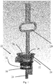
- a first embodiment of the present invention discloses a jig saw (not shown in its entirety), including a clamping assembly 22, a plunger 20 connected to the clamping assembly 22, and a saw blade 24 removably mounted to the clamping assembly 22.
- the saw blade 24 shown here is in the final status of installation, and the length direction of the saw blade 24 (and also the length direction of the plunger 20) is generally parallel to a first axis 42. It can be seen that the first axis 42 is not parallel to the thickness direction 52 of the saw blade 24 when it is installed on the jig saw (see the thickness direction 52 shown in Fig. 6 ).
- the plunger 20 is, as a part of the driving mechanism of the jig saw, adapted to transmit a driving force generated by a motor (not shown) to the clamping assembly 22 in a reciprocating manner.
- the plunger 20 has a generally elongated shape well known to those skilled in the art, the ends of which being connected to the clamping assembly 22 by bolts 26.
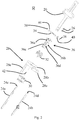
- the clamping assembly 22 specifically includes a rotating lever 28, a sleeve 30, a spring 32, a locking pin 34, a body 36, and the like.
- the body 36 is fixedly connected to the plunger 20 by two of the above-described bolts 26, so that the body 36 is adapted to reciprocate with the plunger 20.
- the two bolts 26 are arranged along the length direction of the plunger 20.
- a rotary lever 28 is nested and provided outside of the body 36. It is to be noted that the rotary lever 28 can rotate relative to the body 36, and does not move with the body 36 while the body 36 reciprocates, but remains stationary.
- the sleeve 30 is also nested and provided outside of the body 36, but the sleeve 30 and the rotary lever 28 are respectively nested and provided at positions of the body 36 near the ends thereof.
- the sleeve 30, as an intermediate member, is adapted to rotate and linearly move relative to the body 36. Such a linear motion occurs in the direction of the first axis 42.
- the sleeve 30 is connected to the body 36 by a spring 32.
- the saw blade 24 is removably mounted to the lower end of the body 36 near the position of the sleeve 30.
- the rotary lever 28 is an actuating member that is in contact with the user's finger for being rotated by the user to effect clamping or unlocking of the saw blade 24 by the clamping assembly 22.
- the rotary lever 28 includes three portions that are connected together, i.e., a connecting ring 28b that is adapted to fit over the body 36, a handle 28a connected to the outer peripheral surface of the connecting ring 28b and projecting generally radially outwardly, and an actuating lever 28c extending from the connecting ring 28b along the first axis 42.
- the handle 28a is adapted to be contacted and pulled by a user's finger, and such a pulling causes the rotation of the connecting ring 28b such that the actuating lever 28c also rotates with the connecting ring 28b.
- the body 36 has a generally elongated shape. On its side surface, there are external threads 36c. It is to be noted that the body 36 does not have a cylindrical appearance, but has a shape similar to a rectangle on a portion thereof having the external threads 36c. Specifically, by reference to Figs. 2 and 3 , the external thread 36c only exists on two surfaces of the four circumferential side surfaces, which are opposite and curved surfaces 36a. Thus, the two curved surfaces 36a together form an arc that is similar to a portion of the side of the cylinder, such that the body can be rotationally coupled to other components by the external threads 36c.
- the other two of the four side surfaces of the body 36 do not have external threads 36c, but they exist as planes 36b. These two planes are primarily intended to form a chute 36d that extends transversely through the entire body 36.
- the locking pin 34 can be retained in the chute 36d by its E-ring 38 and washer 40, respectively, near the ends thereof (as shown in Fig. 3 ), but the locking pin 34 can move in the chute 36d relative to the body 36. It can be seen that the locking pin 34 is perpendicular to the plane 36b described above, but is generally parallel to the curved surface 36a described above. The orientation of the chute 36d is not parallel to the first axis 42 nor perpendicular thereto.
- the locking pin 34 can move simultaneously along the first axis 42 relative to the body 36 and along a second axis 50 parallel to the width direction of the saw blade 24 in the installation site (shown in Fig. 5 ). This will be described in detail below.
- the body 36 and the locking pin 34 together form a clamping part in the clamping member because the locking pin 34 can abut against the saw blade 24 and press it against the inner wall of the body 36, thereby achieving clamping of the saw blade 24.
- the sleeve 30 has a generally cylindrical shape with a hollow portion 44 formed in the center thereof, thereby allowing the body 36 to pass therethrough.
- internal threads 30c are formed on the inner wall of the sleeve 30 adjacent to the hollow portion 44.
- the internal threads 30c are adapted to connect with the external thread 36c on the body 36 described above.
- a radially projecting stopper 30a is formed for contacting and cooperating with the actuating lever 28c of the rotary lever 28 described above.
- a sliding chute 30b for receiving a portion of the locking pin 34 described above is provided in the circumferential direction. It is to be noted that the sliding chute 30b does not have a length around the entire circumference (i.e., 360°).
- Fig. 5 shows how the sleeve 30 is connected to the body 36 by the spring 32 and the locking pin 34.
- the rotary lever 28 is omitted here for clearer display.
- the sleeve 30 is threadedly connected to the body 36 by threads as described above, so that the sleeve 30 can rotate and linearly move relative to the body 36 at the same time.
- the spring 32 connects the sleeve 30 and the body 36 and as a biasing member biases the sleeve 30 in the locked position as shown in Fig. 5 .
- each of the ends of the locking pin 34 sequentially passes through the chute 36d on the body 36 and the sliding chute 30b on the sleeve 30.
- the E-ring 38 and the washer 40 are located between the chute 36d and the sliding chute 30b, and as a spacer to prevent the motion of the locking pin 34 in the chute 36d and the frictional interference in the motion in the sliding chute 30b.
- the sleeve 30 and the body 36 described above constitute a motion conversion mechanism of the clamping member in the present embodiment, which is adapted to convert the rotation about the first axis 42 into a linear motion in the direction of the first axis 42.
- Fig. 2 Also shown in Fig. 2 are two exemplary saw blades that can be used in the jig saw in this embodiment, namely a T-shunk saw blade 24a and a U-shank saw blade 24b, respectively.
- the main difference between the two is that the tip end of the clamping end of the T-shunk saw blade 24a has an inverted "V" shape, and a recess and a pair of protrusions are formed in the subsequent portion of the inverted "V" shape, thereby forming a shape similar to the shape of the word "T".
- the U-shank saw blade 24b does not have the above-described recesses and projections, and its clamping end has a generally straight appearance, but the tip end of the U-shank saw blade 24b has a U-shape, which is also the origin of its name.
- FIG. 6 shows how to operate the rotary lever by the user to unlock or clamp the saw blade 24 inserted into the clamping assembly. Specifically, as described above, if there is no external force interference by the user, the clamping assembly is in the clamped position by default, which is achieved by the spring 32 applying a pressure to the sleeve 30. If the user wants to remove the saw blade 24 that is being clamped, the user manually pulls the handle 28a in a clockwise direction as indicated by arrow 46. The rotation of the handle 28a causes the connecting member 28b, and the actuating lever 28c connected to the connecting member 28b to rotate around the body 36.
- the clockwise rotation of the actuating lever 28c drives the sleeve 30 to simultaneously rotate.
- the sleeve 30 is connected to the body 36 by threads as described above, so the sleeve 30 is driven to rotate while moving upward in the direction indicated by the arrow 48 due to the threads.
- the locking pin 34 is caught in the sliding chute 30b of the sleeve 30, and the sliding chute 30b has a circumferentially extending direction substantially perpendicular to the first axis 42, the sleeve 30 moving upward along the first axis 42 will force the locking pin 34 to move upwardly at the same time.
- Upward motion of the locking pin 34 is possible because the locking pin 34 is received in a chute (not shown in Fig. 6 ) of the body 36, which allows the locking pin 34 to move upwardly along the direction of the first axis and simultaneously move in a direction away from the saw blade 24 in the direction of the second axis. Neither the first axis nor the second axis is shown in Fig. 6 , but is shown in Figs. 2 and 5 , respectively. As a result, the locking pin 34 no longer contacts the saw blade 24, thereby releasing the clamping of the saw blade 24. The user can then remove the saw blade 24 and replace it with a new one.
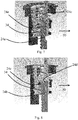
- Figs. 7 and 8 are schematic views respectively showing the clamping of T-shank saw blade 24a and the U-shank saw blade 24b by the jig saw clamping member in the above-described embodiment.
- the common point of the two types of saw blades when they are clamped is that there is no mechanism in the clamping mechanism that needs to contact the tip end face 24c of the T-shank saw blade 24a or the tip end face 24d of the U-shank saw blade 24b.
- the above-described locking pin 34 merely abuts against the side edge 24e of the T-shank saw blade 24a or the U-shank saw blade 24b, that is, applies clamping force along the width direction of the T-shank saw blade 24a and the U-shank saw blade 24b.
- Such a design can correspond not only to the T-shank saw blade 24a and the U-shank saw blade 24b, but also to any other type of saw blades.
- the locking pin is used to clamp the side edge of the saw blade (i.e., the edge having thickness).
- the invention may also be designed to clamp the side surface of the saw blade (i.e., the side having the width) by means of a locking pin.
Landscapes
- Engineering & Computer Science (AREA)
- Mechanical Engineering (AREA)
- Life Sciences & Earth Sciences (AREA)
- Wood Science & Technology (AREA)
- Forests & Forestry (AREA)
- Sawing (AREA)
Abstract
Description
- The disclosure relates to a jig saw, and more particularly to a clamping member for clamping a saw blade in a jig saw.
- Jig saws are widely used for cutting various sheets such as those made from wood and metal, and are suitable for cutting curved shapes on these sheets. The working principle of jig saws is that by rotation of a motor, the saw blade is driven for reciprocating movement through a conversion mechanism. Since the saw blade is easily worn after a large number of cutting operations, the saw blade clamping mechanism of jig saws is usually designed to clamp or unlock the saw blade by human hands, thereby facilitating replacement of the worn saw blade by the user.
- However, mechanisms for clamping the saw blade in the existing jig saws are not fully up to expectations. For example, many clamping mechanisms in jig saws can only be used with saw blades of a particular shape, such as a T-saw blade with a T-shaped end, or a U-saw blade with a U-shaped end, but not both. Such a design results in limited types of saw blade that can be used by the jig saws, which is not convenient for the user's operation. In addition, many clamping mechanisms require the user to perform complicated operations to lock or unlock the saw blade, or require a large strength to use, which is inconvenient for the user.
- Thus, an embodiment of the present invention provides a jig saw that contains a clamping assembly for removably clamping a saw blade and a drive mechanism. The clamping assembly is connected to the drive mechanism. The clamping assembly contains an actuating member and a clamping member. The actuating member is configured to rotate about a first axis to drive the clamping member to effect locking or unlocking of the saw blade. The first axis is not parallel to a thickness direction of the saw blade when it is installed on the jig saw.
- The first axis may be substantially parallel to a length direction of the saw blade when it is installed on the jig saw.
- The clamping assembly may further include a motion conversion mechanism adapted to convert a rotational motion about the first axis to a linear motion along the length direction.
- The motion conversion mechanism may contain an intermediate member and a fixing member. The intermediate member may include one of an internal thread and an external thread, and the fixing member may be fixedly connected to the drive member and contain the other one of the internal thread and the external thread. The intermediate member may be adapted to be driven by the actuating member to rotate around the fixing member, and during the rotation the intermediate member may simultaneously move relative to the fixing member linearly.
- The clamping member may contain a body and a clamping piece. The body may act as the fixing member of the motion conversion mechanism. The clamping piece may be adapted to be driven by the intermediate member to perform the linear motion, and the clamping piece may be adapted to move along a second axis during the linear motion to effect locking or unlocking of the saw blade.
- The clamping piece may be a locking pin and the body may include a chute; said locking pin may be received within the chute and adapted to move along the chute. The orientation of the chute may be neither parallel to the first axis nor perpendicular to the first axis.
- The second axis may be parallel to a width direction of the saw blade when it is installed on the jig saw.
- The clamping assembly may further contain a biasing member adapted to bias the actuating member, such that the clamping member is at a locked position when no external force is applied.
- The clamping assembly may be suitable for both a U-shank saw blade and a T-shank saw blade.
- The jig saw in the present invention thus overcomes the aforementioned technical problems. First, since the pressure is applied to the side of the saw blade by the clamping mechanism of the jig saws by means of the clamping member, and then the saw blade is pressed against the body and be fixed on the body, the clamping mechanism can be applied to different types of saw blades regardless of the shape of the end face of the clamping end (for example, V-shaped or U-shaped). Rather, since the saw blades each have a shape of a strip with a substantially thin sheet shape, the clamping mechanism of the present invention can firmly clamp the saw blades. Such a design greatly expands the type of saw blade that can be used on the same jig saw, which allows the user to easily load different types of saw blades on the jig saw without any need of replacing the jig saw or using additional tools.
- Further, the actuating member operable by the user in the clamping mechanism of the present invention is designed in the form of a rotating lever, and such rotation can be converted into a linear motion of the clamping member by the motion conversion mechanism. The design of a rotating lever amplifies the user's torque using the lever principle, so that the user can operate the actuating member without a lot of efforts. This design makes it easier and quicker for users to replace the saw blade.
- Any feature or features from one aspect, embodiment or implementation as is described herein may be combined with any other aspect, embodiment or implementation, or feature or features thereof, as is described herein, as appropriate and applicable.
- The performances and advantages of the present invention will be further understood by reference to the rest of the specification and the accompanying drawings. The reference numerals in the accompanying drawings are the same for each component. In some cases, a sub-tag is placed after a label and hyphen to represent one of many similar components. When referring to a label but not specifically stating one existing sub-tag, it refers to all of these similar components.
-
Fig. 1 is a schematic view of the appearance of a clamping mechanism in a jig saw according to one embodiment of the present invention, wherein the rotating lever is displayed in a translucent manner to show other components located inside thereof. -
Fig. 2 is an exploded view of the components of the clamping mechanism ofFig. 1 . -
Fig. 3 is an enlarged perspective view showing a locking pin and peripheral members in the clamping mechanism ofFig. 1 . -
Fig. 4 shows the appearance of the intermediate member of the clamping mechanism ofFig. 1 alone. -
Fig. 5 is an enlarged schematic view of the motion conversion mechanism of the clamping mechanism ofFig. 1 , and the intermediate member is translucent to show the threads therein. -
Fig. 6 is a schematic view showing the operation process of the clamping mechanism ofFig. 1 . -
Fig. 7 is a schematic view showing the clamping mechanism ofFig. 1 clamping a T-shank saw blade. -
Fig. 8 is a schematic view showing the clamping mechanism ofFig. 1 clamping a U-shank saw blade. - Embodiments of the present invention use a motion conversion mechanism to convert the rotation of the rotary lever by the users into a tilted linear motion of the clamping mechanism, thus such a tilted linear motion enables the saw blade to be clamped or unlocked. Other different benefits and advantages provided by the various embodiments of the present invention can be easily apparent from the following description.
- Referring firstly to
Figs. 1 and2 , a first embodiment of the present invention discloses a jig saw (not shown in its entirety), including aclamping assembly 22, aplunger 20 connected to theclamping assembly 22, and asaw blade 24 removably mounted to theclamping assembly 22. Thesaw blade 24 shown here is in the final status of installation, and the length direction of the saw blade 24 (and also the length direction of the plunger 20) is generally parallel to afirst axis 42. It can be seen that thefirst axis 42 is not parallel to thethickness direction 52 of thesaw blade 24 when it is installed on the jig saw (see thethickness direction 52 shown inFig. 6 ). Here, theplunger 20 is, as a part of the driving mechanism of the jig saw, adapted to transmit a driving force generated by a motor (not shown) to theclamping assembly 22 in a reciprocating manner. Theplunger 20 has a generally elongated shape well known to those skilled in the art, the ends of which being connected to theclamping assembly 22 bybolts 26. Theclamping assembly 22 specifically includes arotating lever 28, asleeve 30, aspring 32, alocking pin 34, abody 36, and the like. Here, thebody 36 is fixedly connected to theplunger 20 by two of the above-describedbolts 26, so that thebody 36 is adapted to reciprocate with theplunger 20. The twobolts 26 are arranged along the length direction of theplunger 20. Arotary lever 28 is nested and provided outside of thebody 36. It is to be noted that therotary lever 28 can rotate relative to thebody 36, and does not move with thebody 36 while thebody 36 reciprocates, but remains stationary. Thesleeve 30 is also nested and provided outside of thebody 36, but thesleeve 30 and therotary lever 28 are respectively nested and provided at positions of thebody 36 near the ends thereof. Thesleeve 30, as an intermediate member, is adapted to rotate and linearly move relative to thebody 36. Such a linear motion occurs in the direction of thefirst axis 42. Thesleeve 30 is connected to thebody 36 by aspring 32. Thesaw blade 24 is removably mounted to the lower end of thebody 36 near the position of thesleeve 30. - In the present embodiment, the
rotary lever 28 is an actuating member that is in contact with the user's finger for being rotated by the user to effect clamping or unlocking of thesaw blade 24 by the clampingassembly 22. As most clearly shown inFig. 2 , therotary lever 28 includes three portions that are connected together, i.e., a connectingring 28b that is adapted to fit over thebody 36, ahandle 28a connected to the outer peripheral surface of the connectingring 28b and projecting generally radially outwardly, and anactuating lever 28c extending from the connectingring 28b along thefirst axis 42. Thehandle 28a is adapted to be contacted and pulled by a user's finger, and such a pulling causes the rotation of the connectingring 28b such that theactuating lever 28c also rotates with the connectingring 28b. - As also clearly shown in
Fig. 2 , thebody 36 has a generally elongated shape. On its side surface, there areexternal threads 36c. It is to be noted that thebody 36 does not have a cylindrical appearance, but has a shape similar to a rectangle on a portion thereof having theexternal threads 36c. Specifically, by reference toFigs. 2 and3 , theexternal thread 36c only exists on two surfaces of the four circumferential side surfaces, which are opposite andcurved surfaces 36a. Thus, the twocurved surfaces 36a together form an arc that is similar to a portion of the side of the cylinder, such that the body can be rotationally coupled to other components by theexternal threads 36c. However, the other two of the four side surfaces of thebody 36 do not haveexternal threads 36c, but they exist asplanes 36b. These two planes are primarily intended to form achute 36d that extends transversely through theentire body 36. The lockingpin 34 can be retained in thechute 36d by its E-ring 38 andwasher 40, respectively, near the ends thereof (as shown inFig. 3 ), but the lockingpin 34 can move in thechute 36d relative to thebody 36. It can be seen that the lockingpin 34 is perpendicular to theplane 36b described above, but is generally parallel to thecurved surface 36a described above. The orientation of thechute 36d is not parallel to thefirst axis 42 nor perpendicular thereto. In particular, the lockingpin 34 can move simultaneously along thefirst axis 42 relative to thebody 36 and along asecond axis 50 parallel to the width direction of thesaw blade 24 in the installation site (shown inFig. 5 ). This will be described in detail below. Thebody 36 and the lockingpin 34 together form a clamping part in the clamping member because the lockingpin 34 can abut against thesaw blade 24 and press it against the inner wall of thebody 36, thereby achieving clamping of thesaw blade 24. - Turning now to
Fig. 4 , thesleeve 30 has a generally cylindrical shape with ahollow portion 44 formed in the center thereof, thereby allowing thebody 36 to pass therethrough. On the inner wall of thesleeve 30 adjacent to thehollow portion 44,internal threads 30c are formed. Theinternal threads 30c are adapted to connect with theexternal thread 36c on thebody 36 described above. On the outer peripheral surface of thesleeve 30, aradially projecting stopper 30a is formed for contacting and cooperating with theactuating lever 28c of therotary lever 28 described above. On theside surface 30d of thesleeve 30 near one end thereof, a slidingchute 30b for receiving a portion of the lockingpin 34 described above is provided in the circumferential direction. It is to be noted that the slidingchute 30b does not have a length around the entire circumference (i.e., 360°). -
Fig. 5 shows how thesleeve 30 is connected to thebody 36 by thespring 32 and the lockingpin 34. Therotary lever 28 is omitted here for clearer display. Thesleeve 30 is threadedly connected to thebody 36 by threads as described above, so that thesleeve 30 can rotate and linearly move relative to thebody 36 at the same time. Thespring 32 connects thesleeve 30 and thebody 36 and as a biasing member biases thesleeve 30 in the locked position as shown inFig. 5 . In addition, each of the ends of the lockingpin 34 sequentially passes through thechute 36d on thebody 36 and the slidingchute 30b on thesleeve 30. The E-ring 38 and thewasher 40 are located between thechute 36d and the slidingchute 30b, and as a spacer to prevent the motion of the lockingpin 34 in thechute 36d and the frictional interference in the motion in the slidingchute 30b. Thesleeve 30 and thebody 36 described above constitute a motion conversion mechanism of the clamping member in the present embodiment, which is adapted to convert the rotation about thefirst axis 42 into a linear motion in the direction of thefirst axis 42. - Also shown in
Fig. 2 are two exemplary saw blades that can be used in the jig saw in this embodiment, namely a T-shunk saw blade 24a and aU-shank saw blade 24b, respectively. The main difference between the two is that the tip end of the clamping end of the T-shunk saw blade 24a has an inverted "V" shape, and a recess and a pair of protrusions are formed in the subsequent portion of the inverted "V" shape, thereby forming a shape similar to the shape of the word "T". The U-shank sawblade 24b does not have the above-described recesses and projections, and its clamping end has a generally straight appearance, but the tip end of the U-shank sawblade 24b has a U-shape, which is also the origin of its name. - Let us now look at the working principle of the jig saws clamping member in the above embodiment.
Fig. 6 shows how to operate the rotary lever by the user to unlock or clamp thesaw blade 24 inserted into the clamping assembly. Specifically, as described above, if there is no external force interference by the user, the clamping assembly is in the clamped position by default, which is achieved by thespring 32 applying a pressure to thesleeve 30. If the user wants to remove thesaw blade 24 that is being clamped, the user manually pulls thehandle 28a in a clockwise direction as indicated byarrow 46. The rotation of thehandle 28a causes the connectingmember 28b, and theactuating lever 28c connected to the connectingmember 28b to rotate around thebody 36. Since theactuating lever 28c abuts against thestopper 30a on thesleeve 30, the clockwise rotation of theactuating lever 28c drives thesleeve 30 to simultaneously rotate. However, thesleeve 30 is connected to thebody 36 by threads as described above, so thesleeve 30 is driven to rotate while moving upward in the direction indicated by thearrow 48 due to the threads. At the same time, since the lockingpin 34 is caught in the slidingchute 30b of thesleeve 30, and the slidingchute 30b has a circumferentially extending direction substantially perpendicular to thefirst axis 42, thesleeve 30 moving upward along thefirst axis 42 will force the lockingpin 34 to move upwardly at the same time. Upward motion of the lockingpin 34 is possible because the lockingpin 34 is received in a chute (not shown inFig. 6 ) of thebody 36, which allows the lockingpin 34 to move upwardly along the direction of the first axis and simultaneously move in a direction away from thesaw blade 24 in the direction of the second axis. Neither the first axis nor the second axis is shown inFig. 6 , but is shown inFigs. 2 and5 , respectively. As a result, the lockingpin 34 no longer contacts thesaw blade 24, thereby releasing the clamping of thesaw blade 24. The user can then remove thesaw blade 24 and replace it with a new one. During this process, one of the user's hands must always pull thehandle 28a to overcome the elastic force of thespring 32, otherwise the clamping assembly will automatically return to the clamping position. If the new saw blade is replaced and is in the clamping assembly, the user can release thehandle 28a and the clamping assembly re-clamps the saw blade by the exact opposite course of the process described above. -
Figs. 7 and 8 are schematic views respectively showing the clamping of T-shank sawblade 24a and the U-shank sawblade 24b by the jig saw clamping member in the above-described embodiment. The common point of the two types of saw blades when they are clamped is that there is no mechanism in the clamping mechanism that needs to contact thetip end face 24c of the T-shank sawblade 24a or thetip end face 24d of the U-shank sawblade 24b. In contrast, the above-describedlocking pin 34 merely abuts against theside edge 24e of the T-shank sawblade 24a or the U-shank sawblade 24b, that is, applies clamping force along the width direction of the T-shank sawblade 24a and the U-shank sawblade 24b. Such a design can correspond not only to the T-shank sawblade 24a and the U-shank sawblade 24b, but also to any other type of saw blades. - Having thus described several embodiments, those skilled in the art will recognize that various modifications, other structures, and equivalents can be used without departing from the scope of the invention. Correspondingly, the above description should not be taken as limitation to the scope of the invention as defined by the following claims.
- For example, in the above embodiment, the locking pin is used to clamp the side edge of the saw blade (i.e., the edge having thickness). However, in other variations, the invention may also be designed to clamp the side surface of the saw blade (i.e., the side having the width) by means of a locking pin.
Claims (9)
- A jig saw, comprising a clamping assembly for removably clamping a saw blade and a drive mechanism, wherein the clamping assembly is connected to the drive mechanism, characterized in that the clamping assembly comprises an actuating member and a clamping member; the actuating member configured to rotate about a first axis to drive the clamping member to effect locking or unlocking of the saw blade; wherein the first axis is not parallel to a thickness direction of the saw blade when it is installed on the jig saw.
- The jig saw according to claim 1, wherein the first axis is substantially parallel to a length direction of the saw blade when it is installed on the jig saw.
- The jig saw according to claim 1 or 2, wherein the clamping assembly further comprises a motion conversion mechanism adapted to convert a rotational motion about the first axis to a linear motion along the length direction.
- The jig saw according to claim 3, wherein the motion conversion mechanism comprises an intermediate member and a fixing member, the intermediate member comprising one of an internal thread and an external thread, and the fixing member fixedly connected to the drive member and comprising the other one of the internal thread and the external thread; the intermediate member adapted to be driven by the actuating member to rotate around the fixing member, and during the rotation the intermediate member simultaneously moving relative to the fixing member linearly.
- The jig saw according to claim 4, wherein the clamping member comprises a body and a clamping piece; the body acting as the fixing member of the motion conversion mechanism; the clamping piece adapted to be driven by the intermediate member to perform the linear motion, and the clamping piece adapted to move along a second axis during the linear motion to effect locking or unlocking of the saw blade.
- The jig saw according to claim 5, wherein the clamping piece is a locking pin and said body includes a chute; said locking pin received within said chute and adapted to move along the chute; the orientation of the chute being neither parallel to the first axis nor perpendicular to the first axis.
- The jig saw according to claim 5 or 6, wherein the second axis is parallel to a width direction of the saw blade when it is installed on the jig saw.
- The jig saw according to any one of claims 1 to 7, wherein the clamping assembly further comprises a biasing member adapted to bias the actuating member, such that the clamping member is at a locked position when no external force is applied.
- The jig saw according to any one of claims 1 to 8, wherein the clamping assembly is suitable for both a U-shank saw blade and a T-shank saw blade.
Applications Claiming Priority (1)
| Application Number | Priority Date | Filing Date | Title |
|---|---|---|---|
| CN201810095825.4A CN110091000B (en) | 2018-01-31 | 2018-01-31 | Curve saw with clamping member |
Publications (2)
| Publication Number | Publication Date |
|---|---|
| EP3520942A1 true EP3520942A1 (en) | 2019-08-07 |
| EP3520942B1 EP3520942B1 (en) | 2021-12-22 |
Family
ID=65041700
Family Applications (1)
| Application Number | Title | Priority Date | Filing Date |
|---|---|---|---|
| EP19152649.0A Active EP3520942B1 (en) | 2018-01-31 | 2019-01-18 | Jigsaw with blade clamping mechanism |
Country Status (2)
| Country | Link |
|---|---|
| EP (1) | EP3520942B1 (en) |
| CN (1) | CN110091000B (en) |
Citations (3)
| Publication number | Priority date | Publication date | Assignee | Title |
|---|---|---|---|---|
| US5306025A (en) * | 1991-11-27 | 1994-04-26 | Altas Copco Elektrowerkzeuge Gmbh | Clamping device for a compass sawing machine |
| US5903983A (en) * | 1994-11-29 | 1999-05-18 | Milwaukee Electric Tool Corp. | Keyless clamp assembly for reciprocating tool |
| US20070131076A1 (en) * | 2005-12-13 | 2007-06-14 | Chen Yasheng | Saw blade clamping assembly for reciprocating saw |
Family Cites Families (3)
| Publication number | Priority date | Publication date | Assignee | Title |
|---|---|---|---|---|
| CN2644065Y (en) * | 2003-09-05 | 2004-09-29 | 力武电机股份有限公司 | Clamping Mechanism of Saw Blade of Reciprocating Chainsaw |
| DE102004042026A1 (en) * | 2004-08-31 | 2006-03-02 | Robert Bosch Gmbh | Clamping device for tool-free clamping of a saw blade |
| CN201824016U (en) * | 2010-05-18 | 2011-05-11 | 南京德朔实业有限公司 | Saw blade clamping device |
-
2018
- 2018-01-31 CN CN201810095825.4A patent/CN110091000B/en active Active
-
2019
- 2019-01-18 EP EP19152649.0A patent/EP3520942B1/en active Active
Patent Citations (3)
| Publication number | Priority date | Publication date | Assignee | Title |
|---|---|---|---|---|
| US5306025A (en) * | 1991-11-27 | 1994-04-26 | Altas Copco Elektrowerkzeuge Gmbh | Clamping device for a compass sawing machine |
| US5903983A (en) * | 1994-11-29 | 1999-05-18 | Milwaukee Electric Tool Corp. | Keyless clamp assembly for reciprocating tool |
| US20070131076A1 (en) * | 2005-12-13 | 2007-06-14 | Chen Yasheng | Saw blade clamping assembly for reciprocating saw |
Also Published As
| Publication number | Publication date |
|---|---|
| CN110091000A (en) | 2019-08-06 |
| EP3520942B1 (en) | 2021-12-22 |
| CN110091000B (en) | 2023-04-28 |
Similar Documents
| Publication | Publication Date | Title |
|---|---|---|
| CN100425380C (en) | Tool-less blade holder for changing the saw blade of a reciprocating tool | |
| JP5019535B2 (en) | Handheld power tool with tool clamping device | |
| US9821430B2 (en) | Power tools | |
| US8317574B2 (en) | Power-driven hand tool with clamping fixture for a tool | |
| CN106475975B (en) | Hand-held tool and clamping device thereof | |
| US8205342B2 (en) | Rotating spindle for a reciprocating saw | |
| CN102233537B (en) | Hand-held power tool with quick clamping device for working element | |
| CN201669688U (en) | Hand-held power tools with quick clamping device for working elements | |
| JP2011255449A (en) | Blade mounting device in reciprocating cutting tool | |
| EP1518629A1 (en) | Clamping apparatus for a tool component and an improved scrolling mechanism | |
| CN111246972A (en) | Reversible ratchet wrench | |
| US10549449B2 (en) | Tool free bolt system for a saw blade | |
| JP2001500795A (en) | Keyless blade clamp mechanism | |
| JP5937224B2 (en) | Electric trimmer | |
| CN108274435A (en) | Power tool | |
| CN100421852C (en) | Reciprocating tools and scroll collars used thereon and assemblies forming them | |
| EP3520942B1 (en) | Jigsaw with blade clamping mechanism | |
| WO2016059821A1 (en) | Clutch device | |
| US10953480B2 (en) | Saw blade quick release mechanism for sawing tool and the sawing tool using the same | |
| CN210306014U (en) | Jigsaw with clamping member | |
| CN103846968B (en) | Angle adjustment device for sawing machine | |
| AU2011276943B2 (en) | A handle mounting assembly | |
| CN106312954B (en) | Hand-held tool and clamping device thereof | |
| CN106312955B (en) | Hand-held tool and clamping device thereof | |
| CN110732726B (en) | Portable cutting machine |
Legal Events
| Date | Code | Title | Description |
|---|---|---|---|
| PUAI | Public reference made under article 153(3) epc to a published international application that has entered the european phase |
Free format text: ORIGINAL CODE: 0009012 |
|
| STAA | Information on the status of an ep patent application or granted ep patent |
Free format text: STATUS: THE APPLICATION HAS BEEN PUBLISHED |
|
| AK | Designated contracting states |
Kind code of ref document: A1 Designated state(s): AL AT BE BG CH CY CZ DE DK EE ES FI FR GB GR HR HU IE IS IT LI LT LU LV MC MK MT NL NO PL PT RO RS SE SI SK SM TR |
|
| AX | Request for extension of the european patent |
Extension state: BA ME |
|
| STAA | Information on the status of an ep patent application or granted ep patent |
Free format text: STATUS: REQUEST FOR EXAMINATION WAS MADE |
|
| 17P | Request for examination filed |
Effective date: 20191007 |
|
| RBV | Designated contracting states (corrected) |
Designated state(s): AL AT BE BG CH CY CZ DE DK EE ES FI FR GB GR HR HU IE IS IT LI LT LU LV MC MK MT NL NO PL PT RO RS SE SI SK SM TR |
|
| RAP1 | Party data changed (applicant data changed or rights of an application transferred) |
Owner name: TTI (MACAO COMMERCIAL OFFSHORE) LIMITED |
|
| GRAP | Despatch of communication of intention to grant a patent |
Free format text: ORIGINAL CODE: EPIDOSNIGR1 |
|
| STAA | Information on the status of an ep patent application or granted ep patent |
Free format text: STATUS: GRANT OF PATENT IS INTENDED |
|
| RIC1 | Information provided on ipc code assigned before grant |
Ipc: B23D 51/10 20060101AFI20210603BHEP |
|
| INTG | Intention to grant announced |
Effective date: 20210707 |
|
| RAP1 | Party data changed (applicant data changed or rights of an application transferred) |
Owner name: TECHTRONIC CORDLESS GP |
|
| GRAS | Grant fee paid |
Free format text: ORIGINAL CODE: EPIDOSNIGR3 |
|
| GRAA | (expected) grant |
Free format text: ORIGINAL CODE: 0009210 |
|
| STAA | Information on the status of an ep patent application or granted ep patent |
Free format text: STATUS: THE PATENT HAS BEEN GRANTED |
|
| AK | Designated contracting states |
Kind code of ref document: B1 Designated state(s): AL AT BE BG CH CY CZ DE DK EE ES FI FR GB GR HR HU IE IS IT LI LT LU LV MC MK MT NL NO PL PT RO RS SE SI SK SM TR |
|
| REG | Reference to a national code |
Ref country code: GB Ref legal event code: FG4D |
|
| REG | Reference to a national code |
Ref country code: CH Ref legal event code: EP |
|
| REG | Reference to a national code |
Ref country code: DE Ref legal event code: R096 Ref document number: 602019010162 Country of ref document: DE |
|
| REG | Reference to a national code |
Ref country code: AT Ref legal event code: REF Ref document number: 1456759 Country of ref document: AT Kind code of ref document: T Effective date: 20220115 |
|
| REG | Reference to a national code |
Ref country code: IE Ref legal event code: FG4D |
|
| REG | Reference to a national code |
Ref country code: LT Ref legal event code: MG9D |
|
| PG25 | Lapsed in a contracting state [announced via postgrant information from national office to epo] |
Ref country code: RS Free format text: LAPSE BECAUSE OF FAILURE TO SUBMIT A TRANSLATION OF THE DESCRIPTION OR TO PAY THE FEE WITHIN THE PRESCRIBED TIME-LIMIT Effective date: 20211222 Ref country code: LT Free format text: LAPSE BECAUSE OF FAILURE TO SUBMIT A TRANSLATION OF THE DESCRIPTION OR TO PAY THE FEE WITHIN THE PRESCRIBED TIME-LIMIT Effective date: 20211222 Ref country code: FI Free format text: LAPSE BECAUSE OF FAILURE TO SUBMIT A TRANSLATION OF THE DESCRIPTION OR TO PAY THE FEE WITHIN THE PRESCRIBED TIME-LIMIT Effective date: 20211222 Ref country code: BG Free format text: LAPSE BECAUSE OF FAILURE TO SUBMIT A TRANSLATION OF THE DESCRIPTION OR TO PAY THE FEE WITHIN THE PRESCRIBED TIME-LIMIT Effective date: 20220322 |
|
| REG | Reference to a national code |
Ref country code: NL Ref legal event code: MP Effective date: 20211222 |
|
| REG | Reference to a national code |
Ref country code: AT Ref legal event code: MK05 Ref document number: 1456759 Country of ref document: AT Kind code of ref document: T Effective date: 20211222 |
|
| PG25 | Lapsed in a contracting state [announced via postgrant information from national office to epo] |
Ref country code: SE Free format text: LAPSE BECAUSE OF FAILURE TO SUBMIT A TRANSLATION OF THE DESCRIPTION OR TO PAY THE FEE WITHIN THE PRESCRIBED TIME-LIMIT Effective date: 20211222 Ref country code: NO Free format text: LAPSE BECAUSE OF FAILURE TO SUBMIT A TRANSLATION OF THE DESCRIPTION OR TO PAY THE FEE WITHIN THE PRESCRIBED TIME-LIMIT Effective date: 20220322 Ref country code: LV Free format text: LAPSE BECAUSE OF FAILURE TO SUBMIT A TRANSLATION OF THE DESCRIPTION OR TO PAY THE FEE WITHIN THE PRESCRIBED TIME-LIMIT Effective date: 20211222 Ref country code: HR Free format text: LAPSE BECAUSE OF FAILURE TO SUBMIT A TRANSLATION OF THE DESCRIPTION OR TO PAY THE FEE WITHIN THE PRESCRIBED TIME-LIMIT Effective date: 20211222 Ref country code: GR Free format text: LAPSE BECAUSE OF FAILURE TO SUBMIT A TRANSLATION OF THE DESCRIPTION OR TO PAY THE FEE WITHIN THE PRESCRIBED TIME-LIMIT Effective date: 20220323 |
|
| PG25 | Lapsed in a contracting state [announced via postgrant information from national office to epo] |
Ref country code: NL Free format text: LAPSE BECAUSE OF FAILURE TO SUBMIT A TRANSLATION OF THE DESCRIPTION OR TO PAY THE FEE WITHIN THE PRESCRIBED TIME-LIMIT Effective date: 20211222 |
|
| PG25 | Lapsed in a contracting state [announced via postgrant information from national office to epo] |
Ref country code: SM Free format text: LAPSE BECAUSE OF FAILURE TO SUBMIT A TRANSLATION OF THE DESCRIPTION OR TO PAY THE FEE WITHIN THE PRESCRIBED TIME-LIMIT Effective date: 20211222 Ref country code: SK Free format text: LAPSE BECAUSE OF FAILURE TO SUBMIT A TRANSLATION OF THE DESCRIPTION OR TO PAY THE FEE WITHIN THE PRESCRIBED TIME-LIMIT Effective date: 20211222 Ref country code: RO Free format text: LAPSE BECAUSE OF FAILURE TO SUBMIT A TRANSLATION OF THE DESCRIPTION OR TO PAY THE FEE WITHIN THE PRESCRIBED TIME-LIMIT Effective date: 20211222 Ref country code: PT Free format text: LAPSE BECAUSE OF FAILURE TO SUBMIT A TRANSLATION OF THE DESCRIPTION OR TO PAY THE FEE WITHIN THE PRESCRIBED TIME-LIMIT Effective date: 20220422 Ref country code: ES Free format text: LAPSE BECAUSE OF FAILURE TO SUBMIT A TRANSLATION OF THE DESCRIPTION OR TO PAY THE FEE WITHIN THE PRESCRIBED TIME-LIMIT Effective date: 20211222 Ref country code: EE Free format text: LAPSE BECAUSE OF FAILURE TO SUBMIT A TRANSLATION OF THE DESCRIPTION OR TO PAY THE FEE WITHIN THE PRESCRIBED TIME-LIMIT Effective date: 20211222 Ref country code: CZ Free format text: LAPSE BECAUSE OF FAILURE TO SUBMIT A TRANSLATION OF THE DESCRIPTION OR TO PAY THE FEE WITHIN THE PRESCRIBED TIME-LIMIT Effective date: 20211222 |
|
| PG25 | Lapsed in a contracting state [announced via postgrant information from national office to epo] |
Ref country code: PL Free format text: LAPSE BECAUSE OF FAILURE TO SUBMIT A TRANSLATION OF THE DESCRIPTION OR TO PAY THE FEE WITHIN THE PRESCRIBED TIME-LIMIT Effective date: 20211222 Ref country code: AT Free format text: LAPSE BECAUSE OF FAILURE TO SUBMIT A TRANSLATION OF THE DESCRIPTION OR TO PAY THE FEE WITHIN THE PRESCRIBED TIME-LIMIT Effective date: 20211222 |
|
| REG | Reference to a national code |
Ref country code: CH Ref legal event code: PL |
|
| REG | Reference to a national code |
Ref country code: DE Ref legal event code: R097 Ref document number: 602019010162 Country of ref document: DE |
|
| PG25 | Lapsed in a contracting state [announced via postgrant information from national office to epo] |
Ref country code: MC Free format text: LAPSE BECAUSE OF FAILURE TO SUBMIT A TRANSLATION OF THE DESCRIPTION OR TO PAY THE FEE WITHIN THE PRESCRIBED TIME-LIMIT Effective date: 20211222 Ref country code: IS Free format text: LAPSE BECAUSE OF FAILURE TO SUBMIT A TRANSLATION OF THE DESCRIPTION OR TO PAY THE FEE WITHIN THE PRESCRIBED TIME-LIMIT Effective date: 20220422 |
|
| REG | Reference to a national code |
Ref country code: BE Ref legal event code: MM Effective date: 20220131 |
|
| PLBE | No opposition filed within time limit |
Free format text: ORIGINAL CODE: 0009261 |
|
| STAA | Information on the status of an ep patent application or granted ep patent |
Free format text: STATUS: NO OPPOSITION FILED WITHIN TIME LIMIT |
|
| PG25 | Lapsed in a contracting state [announced via postgrant information from national office to epo] |
Ref country code: LU Free format text: LAPSE BECAUSE OF NON-PAYMENT OF DUE FEES Effective date: 20220118 Ref country code: DK Free format text: LAPSE BECAUSE OF FAILURE TO SUBMIT A TRANSLATION OF THE DESCRIPTION OR TO PAY THE FEE WITHIN THE PRESCRIBED TIME-LIMIT Effective date: 20211222 Ref country code: AL Free format text: LAPSE BECAUSE OF FAILURE TO SUBMIT A TRANSLATION OF THE DESCRIPTION OR TO PAY THE FEE WITHIN THE PRESCRIBED TIME-LIMIT Effective date: 20211222 |
|
| 26N | No opposition filed |
Effective date: 20220923 |
|
| PG25 | Lapsed in a contracting state [announced via postgrant information from national office to epo] |
Ref country code: BE Free format text: LAPSE BECAUSE OF NON-PAYMENT OF DUE FEES Effective date: 20220131 |
|
| PG25 | Lapsed in a contracting state [announced via postgrant information from national office to epo] |
Ref country code: LI Free format text: LAPSE BECAUSE OF NON-PAYMENT OF DUE FEES Effective date: 20220131 Ref country code: CH Free format text: LAPSE BECAUSE OF NON-PAYMENT OF DUE FEES Effective date: 20220131 |
|
| PG25 | Lapsed in a contracting state [announced via postgrant information from national office to epo] |
Ref country code: IE Free format text: LAPSE BECAUSE OF NON-PAYMENT OF DUE FEES Effective date: 20220118 |
|
| PG25 | Lapsed in a contracting state [announced via postgrant information from national office to epo] |
Ref country code: SI Free format text: LAPSE BECAUSE OF FAILURE TO SUBMIT A TRANSLATION OF THE DESCRIPTION OR TO PAY THE FEE WITHIN THE PRESCRIBED TIME-LIMIT Effective date: 20211222 |
|
| PG25 | Lapsed in a contracting state [announced via postgrant information from national office to epo] |
Ref country code: IT Free format text: LAPSE BECAUSE OF FAILURE TO SUBMIT A TRANSLATION OF THE DESCRIPTION OR TO PAY THE FEE WITHIN THE PRESCRIBED TIME-LIMIT Effective date: 20211222 |
|
| PG25 | Lapsed in a contracting state [announced via postgrant information from national office to epo] |
Ref country code: MK Free format text: LAPSE BECAUSE OF FAILURE TO SUBMIT A TRANSLATION OF THE DESCRIPTION OR TO PAY THE FEE WITHIN THE PRESCRIBED TIME-LIMIT Effective date: 20211222 Ref country code: CY Free format text: LAPSE BECAUSE OF FAILURE TO SUBMIT A TRANSLATION OF THE DESCRIPTION OR TO PAY THE FEE WITHIN THE PRESCRIBED TIME-LIMIT Effective date: 20211222 |
|
| PG25 | Lapsed in a contracting state [announced via postgrant information from national office to epo] |
Ref country code: HU Free format text: LAPSE BECAUSE OF FAILURE TO SUBMIT A TRANSLATION OF THE DESCRIPTION OR TO PAY THE FEE WITHIN THE PRESCRIBED TIME-LIMIT; INVALID AB INITIO Effective date: 20190118 |
|
| PG25 | Lapsed in a contracting state [announced via postgrant information from national office to epo] |
Ref country code: MT Free format text: LAPSE BECAUSE OF FAILURE TO SUBMIT A TRANSLATION OF THE DESCRIPTION OR TO PAY THE FEE WITHIN THE PRESCRIBED TIME-LIMIT Effective date: 20211222 |
|
| PG25 | Lapsed in a contracting state [announced via postgrant information from national office to epo] |
Ref country code: TR Free format text: LAPSE BECAUSE OF FAILURE TO SUBMIT A TRANSLATION OF THE DESCRIPTION OR TO PAY THE FEE WITHIN THE PRESCRIBED TIME-LIMIT Effective date: 20211222 |
|
| PGFP | Annual fee paid to national office [announced via postgrant information from national office to epo] |
Ref country code: GB Payment date: 20260127 Year of fee payment: 8 |
|
| PGFP | Annual fee paid to national office [announced via postgrant information from national office to epo] |
Ref country code: DE Payment date: 20260128 Year of fee payment: 8 |
|
| PGFP | Annual fee paid to national office [announced via postgrant information from national office to epo] |
Ref country code: FR Payment date: 20260126 Year of fee payment: 8 |