EP3520837A1 - A wearable dialysis system - Google Patents
A wearable dialysis system Download PDFInfo
- Publication number
- EP3520837A1 EP3520837A1 EP19163096.1A EP19163096A EP3520837A1 EP 3520837 A1 EP3520837 A1 EP 3520837A1 EP 19163096 A EP19163096 A EP 19163096A EP 3520837 A1 EP3520837 A1 EP 3520837A1
- Authority
- EP
- European Patent Office
- Prior art keywords
- dialysate
- degassing device
- wearable
- gas
- dialyzer
- Prior art date
- Legal status (The legal status is an assumption and is not a legal conclusion. Google has not performed a legal analysis and makes no representation as to the accuracy of the status listed.)
- Withdrawn
Links
Images



Classifications
-
- B—PERFORMING OPERATIONS; TRANSPORTING
- B01—PHYSICAL OR CHEMICAL PROCESSES OR APPARATUS IN GENERAL
- B01D—SEPARATION
- B01D19/00—Degasification of liquids
- B01D19/0031—Degasification of liquids by filtration
-
- A—HUMAN NECESSITIES
- A61—MEDICAL OR VETERINARY SCIENCE; HYGIENE
- A61M—DEVICES FOR INTRODUCING MEDIA INTO, OR ONTO, THE BODY; DEVICES FOR TRANSDUCING BODY MEDIA OR FOR TAKING MEDIA FROM THE BODY; DEVICES FOR PRODUCING OR ENDING SLEEP OR STUPOR
- A61M1/00—Suction or pumping devices for medical purposes; Devices for carrying-off, for treatment of, or for carrying-over, body-liquids; Drainage systems
- A61M1/14—Dialysis systems; Artificial kidneys; Blood oxygenators ; Reciprocating systems for treatment of body fluids, e.g. single needle systems for hemofiltration or pheresis
- A61M1/16—Dialysis systems; Artificial kidneys; Blood oxygenators ; Reciprocating systems for treatment of body fluids, e.g. single needle systems for hemofiltration or pheresis with membranes
- A61M1/1654—Dialysates therefor
- A61M1/1656—Apparatus for preparing dialysates
- A61M1/1658—Degasification
-
- A—HUMAN NECESSITIES
- A61—MEDICAL OR VETERINARY SCIENCE; HYGIENE
- A61M—DEVICES FOR INTRODUCING MEDIA INTO, OR ONTO, THE BODY; DEVICES FOR TRANSDUCING BODY MEDIA OR FOR TAKING MEDIA FROM THE BODY; DEVICES FOR PRODUCING OR ENDING SLEEP OR STUPOR
- A61M1/00—Suction or pumping devices for medical purposes; Devices for carrying-off, for treatment of, or for carrying-over, body-liquids; Drainage systems
- A61M1/14—Dialysis systems; Artificial kidneys; Blood oxygenators ; Reciprocating systems for treatment of body fluids, e.g. single needle systems for hemofiltration or pheresis
- A61M1/16—Dialysis systems; Artificial kidneys; Blood oxygenators ; Reciprocating systems for treatment of body fluids, e.g. single needle systems for hemofiltration or pheresis with membranes
- A61M1/1694—Dialysis systems; Artificial kidneys; Blood oxygenators ; Reciprocating systems for treatment of body fluids, e.g. single needle systems for hemofiltration or pheresis with membranes with recirculating dialysing liquid
- A61M1/1696—Dialysis systems; Artificial kidneys; Blood oxygenators ; Reciprocating systems for treatment of body fluids, e.g. single needle systems for hemofiltration or pheresis with membranes with recirculating dialysing liquid with dialysate regeneration
-
- A—HUMAN NECESSITIES
- A61—MEDICAL OR VETERINARY SCIENCE; HYGIENE
- A61M—DEVICES FOR INTRODUCING MEDIA INTO, OR ONTO, THE BODY; DEVICES FOR TRANSDUCING BODY MEDIA OR FOR TAKING MEDIA FROM THE BODY; DEVICES FOR PRODUCING OR ENDING SLEEP OR STUPOR
- A61M2205/00—General characteristics of the apparatus
- A61M2205/75—General characteristics of the apparatus with filters
Definitions
- the present invention generally relates to the field of hemodialysis, and more specifically to a method and system of efficiently removing carbon dioxide, or any gas, from the dialysate circuit of a dialysis system without compromising the solute-removal performance of a hemodialysis device.
- Closed loop multi-pass sorbent based hemodialyzers have the advantage of being portable and compact while being able to regenerate dialysate using a plurality of sorbents.
- these sorbents are used in disposable cartridges/canisters and comprise sorbent composition layers similar to those used in prior systems, such as urease, zirconium phosphate, hydrous zirconium oxide and activated carbon.
- sorbent composition layers similar to those used in prior systems, such as urease, zirconium phosphate, hydrous zirconium oxide and activated carbon.
- the degassing device needs to be particularly suitable for a portable hemodialyzer, where the orientation of the dialyzer should not disrupt or degrade the efficiency of the degassing device.
- the degassing device needs to be small in size, light and low cost so that it can be a disposable component.
- a portable hemodialyzer such as one configured as a portable artificial kidney (PAK)
- PAK portable artificial kidney
- the degassing device needs to be small in size, light and low cost so that it can be a disposable component.
- the degassing device of the present invention comprises two annular concentric rings that make up inner and outer housings. While the upper end of the inner housing is open, the upper end of the outer housing is sealed with a microporous, hydrophobic membrane that allows gases to pass through but does not allow liquids to pass. A gap is maintained between the open upper end of the inner housing and the membrane.
- the annular concentric housings define an inner first chamber and an outer second chamber.
- dialysate mixed with carbon-dioxide enters into and moves up the outer second chamber causing carbon dioxide to be automatically separated from the dialysate thereby forming small carbon dioxide bubbles that are vented out through the microporous hydrophobic membrane, while the dialysate overflows into the inner first chamber and moves out of the degassing device.
- the present invention is directed to a degassing device comprising a) a first housing having an inlet, a first length and an inner wall defining a first inner chamber, b) a second housing positioned within said first inner chamber in an annular relation to the first housing wherein the second housing has an outer wall, an outlet, a second length and an inner wall defining a second inner chamber, wherein the second length is less than the first length, and wherein a space between the first length and second length defines a gap, c) a flowpath through said degassing device wherein said flowpath is defined by the inlet, the gap, and the outlet, and d) a hydrophobic membrane positioned proximate to said gap.
- the degassing device has a gap between about 0.02 inches and 0.1 inches, has a space between said inner wall of the first housing and outer wall of the second housing between about 0.04 to 0.24 inches, and is capable of removing substantially all gas from dialysate at flow rates between 20 ml/min and 450 ml/min.
- the second housing comprises a filter, the filter is approximately 0.1 to 0.4 inches thick, and the hydrophobic membrane is positioned a distance from the second housing wherein the distance is equal to the gap.
- a dialysate circuit comprises a dialysate regeneration system with urease, a dialyzer, and this degassing device, which is positioned between the urease and the dialyzer.
- the present invention is directed to a dialysate circuit
- a dialysate circuit comprising a) a dialysate regeneration system comprising urease, b) a housing comprising an external wall, wherein the external wall is exposed to atmosphere and wherein the external wall comprises a material that passes gas but does not pass liquid, and c) a dialyzer, wherein said tube is positioned between the urease and dialyzer.
- the housing preferably is just a tube a section of tubing, or a coil of tubing with nothing internal to the tube (the inner chamber defined by the external walls is devoid of any structures or obstructions) and with the external wall exposed to atmosphere, or at least to an area external to the degassing device.
- the dialysate circuit comprises a membrane that is between 0.5 feet to 16 feet long, has an outer diameter of about 0.1 to 0.45 inches, or has an inner diameter of about 0.1 to 0.4 inches.
- the housing degassing device
- the dialysate regeneration system comprises charcoal and the housing is positioned between the charcoal and dialyzer.
- Closed loop multi-pass sorbent based dialysis systems regenerate dialysate for reuse by passing spent dialysate through a regeneration section comprising a plurality of sorbent cartridges and suitable additives.
- a typical sorbent cartridge system comprises a urease cartridge, a zirconium phosphate cartridge, a hydrous zirconium oxide cartridge and an activated carbon cartridge.
- a urease cartridge comprises a urease cartridge, a zirconium phosphate cartridge, a hydrous zirconium oxide cartridge and an activated carbon cartridge.
- the present invention is a degassing device that functions to remove carbon dioxide or any other gas from closed circuit dialysis systems.
- the degassing device of the present invention is suitable for functioning in any orientation apart from being small in size and low cost enough to be disposable thus eliminating the need for periodic cleaning and sterilization.
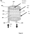
- FIG 4 shows one embodiment of the degassing device 400 of the present invention comprising two annular cylindrical housings 405, 410.
- the housings 405, 410 are concentric.
- the upper end of the inner housing 405 is open and forms a circular rim 404.
- the upper end of the outer housing 410 is sealed with a microporous, hydrophobic membrane 415 that allows gases to pass through but does not allow liquids to pass.
- the hydrophobic membrane can be of any suitable type, including a PALLTM hydrophobic membrane, a GoreTM hydrophobic membrane, including model numbers SMPL-MMT317, MMT-RD-001, MMT-RD-002B and MMT-RD-002A.
- the gap is sized to allow gas bubble passage within the gap. Typical dimensions from .002" to .025", and more particularly from 0.05" to 0.15", have been used in the preferred embodiment.
- the inner housing 405 defines an inner first chamber 401 while the concentric region between the inner and the outer housings 405, 410 constitutes a second chamber 411.
- An inlet tube 420 is connected to an inlet orifice at the second chamber 411 while an outlet tube 425 is connected to an outlet orifice at the first chamber 401.
- the inner first housing 405 has a discontinuous internal surface to provide areas upon which gas within the liquid can nucleate, collect, form bubbles, and migrate up and through the top hydrophobic membrane.
- the inner first housing comprises a filter membrane which is approximately 0.1 to 0.4 inches thick (more particularly 0.25 inches), has an inner diameter of 0.5 to 1.5 inches (more particularly 1 inch), and an outer diameter of 0.5 inches to 2.5 inches (more particularly 1.5 inches).
- the gap at the top, between the inner first housing 405 and hydrophobic membrane 415 is about 0.02 to 0.1 inches (more particularly 0.064), the gap between the outside of the inner first housing 405 and the inner wall of the outer housing 410 is about 0.04 to 0.24 inches (more particularly 0.141 inches), and there is no gap between the inner first housing 405 and the base of the degassing device 400.
- the degassing device 400 has a height of 1 to 5 inches (more particularly three inches) and an outer diameter of .5 to 3 inches (and more particularly 1.75 inches). The degassing device is able to substantially remove all gas from the dialysate at a flow of 20 ml/min to 450 ml/min (more particularly 250 ml/min).
- dialysate mixed with carbon dioxide enters the inlet tube 420 and passes into the concentric second chamber 411, overflows into the inner first chamber 401 through the gap and flows out the outlet tube 425 connected to the first chamber 401.
- the dialysate and carbon dioxide mixture is fed through the inlet tube 420, the mixture moves upwards causing carbon dioxide to be separated from the dialysate thereby forming small carbon dioxide bubbles that are vented out through the microporous hydrophobic membrane 415.
- the dialysate-free carbon dioxide moves through and out the outlet tube 425.
- the degassing chamber can be placed at various locations in the dialysis flow, but preferably in the flow stream immediately after the dialysate is subjected to filtration in sorbent canisters, depicted as 520 in Figures 5a and 5b . It should be appreciated that, regardless of where the degassing chamber is placed in the system, it should be vertically maintained, with membrane 415 at the top of the device, in order to properly direct air bubbles through and out of the device 400.
- Figure 1 shows a closed multi-pass hemodialyzer configured as a wearable dialysis device 100 that, in one embodiment comprises a shuttle pump or dual-channel pulsatile pump 105 to propel both blood and dialysate through the device 100, a high flux, polysulfone dialyzer 110 with 0.6 square meter membrane surface, a dialysate regeneration system 115 consisting of three specially designed canisters containing a plurality of sorbents, such as 122, zirconium, phosphate, 123, activated charcoal, and 121 urease, as well as reservoirs of electrolyte additives 116 and a pH-control circuit (not shown); micro-pumps (not shown) for delivering heparin 117 to the blood circuit, additives including Mg, Ca, K and sodium bicarbonate 118, and a reservoir for excess ultrafiltrate 119, all at pre-specified flow rates; and a blood-leak/bubble detector and pump power-up and alarm/shutoff system 120.
- the main pump 105 uses a 3-Watt DC micro motor.
- the gear-head accommodates an oscillating mechanism, which in conjunction with a dual-channel flow cartridge, allows simultaneous pulsatile flows of both blood and the dialysate at controllable rates of 40-100 ml/min per channel.
- the cartridge allows both blood and dialysate to flow either in the same direction or in opposite directions, depending on the configuration/location of the other system components. It is preferred, however, that, when one channel propels fluid out of its compressible chamber, the other channel fills its compressible chamber, allowing for peak pressure in one channel at the same time the pressure in the other channel is at its lowest level.
- the sorbent canisters of the present invention are filled (in order of dialysate flow) with approximately the following amounts of sorbents:
- Degassing device 124 is located in the fluidic circuit between urease canister 121, and Zirconium Phosphate canister 122. Carbon dioxide gas generated by the urease - urea reaction in canister 121 is removed by the degassing device 124, before the dialysate fluid is passed into canister 122. Other positioning of the degassing device, within the circuit, is possible, in particular after all the sorbent canisters, following the charcoal canister, 123 as shown in figure 5a . It should be appreciated that the degassing device 124 could be located after canister 122 and before canister 123 or after canister 123 and before dialyzer 110.
- the device 520 consists of a coil of gas permeable tubing, such as that manufactured by GORE, Inc., tubing part number MMT-RD-002A.
- the degassing device 520 is connected, via tubing 522, to a dialyzer.
- Figure 5b depicts the degassing device 520 connected to tubing 522.
- This tube is 9 feet long, has an outside diameter of approximately 0.275" and a wall thickness of approximately .025".
- the coil assembly is approximately 2.25" outside diameter and approximately 2.5" in height. In this embodiment, the entire outer wall of the outside chamber is gas permeable.
- the device can be placed in nearly any orientation, making it well suited for use with a wearable dialysis system such as that depicted in Figure 1 .
- the total tube length is 9 feet. This size is designed to yield an adequate surface area to provide gas removal capability for a typical wearable artificial kidney operating around the 24 hours a day, seven days a week with a dialysate and blood flow rate at or below 100 ml/min. Shorter lengths of tubing (therefore possessing lower surface area) can be used for removing less gas, such as if flow rates were lowered or longer lengths can be used for increased gas removal capacity.
- gas collects in a self generated pocket on the top of the many coils of the gas permeable tubing in device 520. This location of the gas pocket changes depending on the orientation of the device. Gravity dictating that the gas collects on whatever surface is "up” in varying orientations. Since the entire length of the device is composed of gas permeable tubing, no matter where the gas pocket collects it is able to escape.
- Alternate packaging of the tube may include long serpentine shaped runs accommodating the shape of a belt worn around the waist of a patient using a wearable artificial kidney.
- the embodiment pictured in Figure 5b is not exclusive to the functionality of the degassing device. The key factor is that whatever shape the device takes the fluid path be composed of a gas permeable tube of sufficient length, and therefore surface area, to remove the amount of gas desired.
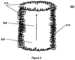
- the degassing device 300 is a section of a tube, a housing, a coil of tubing, or any other shape 310 that defines a chamber 325 and a flowpath 305 therein.
- the external wall of the housing 310 comprises any material 315 that will pass gas but not fluid.
- the material 315 must be sized so that the amount of gas passed equals or exceeds the amount of gas generated.
- Gas generation is a product of urea level in the patient and dialysate flow rate.
- Gas passed by the degassing device 300 is a product of the wall area and the gas permeability of the tube plus the internal pressure of the fluid in the tube relative to the external pressure on the tube.
- One of ordinary skill in the art would be able to select the appropriate material for a given application based upon the given parameters.
- the degassing device comprises a GORE membrane that is between 0.5 feet to 16 feet long (more particularly 9 feet long), has an outer diameter of about 0.1 to 0.45 inches (more particularly .275 inches) and an inner diameter of about 0.1 to 0.4 inches (more particularly .25 inches) and configured in any shape, including a tight coil.
- the aforementioned degassing device 300 removes substantially all gas from the dialysate at flow rates from about 20 ml/min to 200 ml/min (more particularly 100 ml/min) and/or at internal tube pressures at or below 10 psi (more particularly at or below 5 psi).
- the degassing device 300 is positioned between a sorbent canister (more particularly the charcoal sorbent) and the dialyzer. In one embodiment, the degassing device 300 is positioned after the urease canister and before the dialyzer.
- FIG. 2 After priming the dialysis device with saline, the dialysis device 200 was connected to a large (40- to 80-liter) reservoir 205 of properly formulated aqueous solution (referred to as "blood” here, made out of fresh deionized water or spent human dialysate) accurately mimicking end stage renal disease (ESRD) typical human blood.
- blood properly formulated aqueous solution
- ESRD end stage renal disease
- This "blood” was designed to approximate actual human composition and contained about 50 mg/dL of BUN (Blood Urea-Nitrogen), 10 mg/dL of creatinine, 5 mmol/L of K, among other solutes. No additives were provided and no ultrafiltration was performed; however, dialysate pH was maintained at an optimal value by a manual injection of sodium bicarbonate in order to measure its effect on the volume of CO 2 produced. "Blood” and dialysate samples were drawn every 30 minutes, and the samples were assayed for pH, BUN, and creatinine.
- BUN Bood Urea-Nitrogen
- sorbent canisters were packed with 50 grams of urease, 670 grams of zirconium phosphate, 50 grams of hydrous zirconium oxide, and 150 grams of activated carbon, and operated at an average blood and dialysate flow rates of 55.6 and 43.2 mL/min, pressure reading oscillating ranges were measured to be: a) between pump and canister #1: 300-400 mmHg, b) between canisters #1 and #2: 150-220 mmHg, c) between canisters #2 and #3: 55-65 mmHg; and d) between dialyzer and pump: 2-35 mmHg (rarely going below 0).
- the urea measured as BUN (Blood Urea-Nitrogen) when reacted with the Urease generated CO 2 in amounts dictated by the flowrate and urea concentrations present. Such conditions were set up to mimic actual human dialysis. Under these test conditions the degassing device successfully removed all the CO 2 generated.
- BUN Bood Urea-Nitrogen
Landscapes
- Health & Medical Sciences (AREA)
- Urology & Nephrology (AREA)
- Heart & Thoracic Surgery (AREA)
- Anesthesiology (AREA)
- Hematology (AREA)
- Veterinary Medicine (AREA)
- Vascular Medicine (AREA)
- Engineering & Computer Science (AREA)
- Public Health (AREA)
- Biomedical Technology (AREA)
- Emergency Medicine (AREA)
- Life Sciences & Earth Sciences (AREA)
- Animal Behavior & Ethology (AREA)
- General Health & Medical Sciences (AREA)
- Chemical & Material Sciences (AREA)
- Chemical Kinetics & Catalysis (AREA)
- External Artificial Organs (AREA)
- Separation Using Semi-Permeable Membranes (AREA)
- Degasification And Air Bubble Elimination (AREA)
Abstract
a) a wearable dialyzer that removes solutes from impure blood into dialysate;
b) a wearable pump that pumps blood and dialysate through the dialyzer;
c) a wearable dialysate regeneration system comprising urease in fluid communication with the dialysate; and
d) a wearable degassing device in fluid communication with the dialysate regeneration system, the degassing device comprising a dialysate degassing tube having an external wall exposed to atmosphere, the wall comprising a material that is gas permeable and liquid impermeable for each orientation of the degassing device.
Description
- The present application relies on
U.S. Provisional Application No. 61/021,965, filed on January 18, 2008 - The present invention generally relates to the field of hemodialysis, and more specifically to a method and system of efficiently removing carbon dioxide, or any gas, from the dialysate circuit of a dialysis system without compromising the solute-removal performance of a hemodialysis device.
- Closed loop multi-pass sorbent based hemodialyzers have the advantage of being portable and compact while being able to regenerate dialysate using a plurality of sorbents. Typically these sorbents are used in disposable cartridges/canisters and comprise sorbent composition layers similar to those used in prior systems, such as urease, zirconium phosphate, hydrous zirconium oxide and activated carbon. As spent dialysate comprising urea, diffused from impure blood in the dialyzer, passes through prior art sorbent cartridges, carbon dioxide and ammonia are produced as two unwanted byproducts of the chemical reactions. While ammonia is adsorbed in zirconium-based cartridges, carbon dioxide is not captured, mixes in the dialysate, and manifests as carbon dioxide bubbles in the dialysate circuit. Large amounts of carbon dioxide leave the liquid phase and interfere with the smooth pumping of dialysate. In addition other dissolved gases may exit from the liquid phase during processing adding to the volume of gas in the system.
- Accordingly, there is a need for a degassing device that can remove unwanted carbon dioxide, and other gases, from the dialysate circuit. The degassing device needs to be particularly suitable for a portable hemodialyzer, where the orientation of the dialyzer should not disrupt or degrade the efficiency of the degassing device. At the same time, the degassing device needs to be small in size, light and low cost so that it can be a disposable component.
- It is an object of the present invention to provide a degassing device that efficiently vents or removes carbon-dioxide, and other gas, bubbles, from dialysate circuit, that are produced from urea split by urease in the sorbent system of a dialysis device.
- It is also an object of the present invention to have a degassing device that is particularly suitable for a portable hemodialyzer, such as one configured as a portable artificial kidney (PAK), where the orientation of the dialyzer should not disrupt or degrade the efficiency of the degassing device.
- Accordingly, it is another object of the present invention the degassing device needs to be small in size, light and low cost so that it can be a disposable component.
- In one embodiment, the degassing device of the present invention comprises two annular concentric rings that make up inner and outer housings. While the upper end of the inner housing is open, the upper end of the outer housing is sealed with a microporous, hydrophobic membrane that allows gases to pass through but does not allow liquids to pass. A gap is maintained between the open upper end of the inner housing and the membrane. The annular concentric housings define an inner first chamber and an outer second chamber. During dialysis, dialysate mixed with carbon-dioxide enters into and moves up the outer second chamber causing carbon dioxide to be automatically separated from the dialysate thereby forming small carbon dioxide bubbles that are vented out through the microporous hydrophobic membrane, while the dialysate overflows into the inner first chamber and moves out of the degassing device.
- In one embodiment, the present invention is directed to a degassing device comprising a) a first housing having an inlet, a first length and an inner wall defining a first inner chamber, b) a second housing positioned within said first inner chamber in an annular relation to the first housing wherein the second housing has an outer wall, an outlet, a second length and an inner wall defining a second inner chamber, wherein the second length is less than the first length, and wherein a space between the first length and second length defines a gap, c) a flowpath through said degassing device wherein said flowpath is defined by the inlet, the gap, and the outlet, and d) a hydrophobic membrane positioned proximate to said gap.
- Optionally, the degassing device has a gap between about 0.02 inches and 0.1 inches, has a space between said inner wall of the first housing and outer wall of the second housing between about 0.04 to 0.24 inches, and is capable of removing substantially all gas from dialysate at flow rates between 20 ml/min and 450 ml/min. Optionally, the second housing comprises a filter, the filter is approximately 0.1 to 0.4 inches thick, and the hydrophobic membrane is positioned a distance from the second housing wherein the distance is equal to the gap.
- Optionally, the inlet and outlet are positioned on a same side of said degassing device. Fluid having gas flows into the first inner chamber through said inlet, flows through said gap, flows past the hydrophobic membrane, flows into said second inner chamber, and flows through said outlet, wherein gas passes through the hydrophobic membrane and wherein liquid does not pass through said hydrophobic membrane. Optionally, a dialysate circuit comprises a dialysate regeneration system with urease, a dialyzer, and this degassing device, which is positioned between the urease and the dialyzer.
- In another embodiment, the present invention is directed to a dialysate circuit comprising a) a dialysate regeneration system comprising urease, b) a housing comprising an external wall, wherein the external wall is exposed to atmosphere and wherein the external wall comprises a material that passes gas but does not pass liquid, and c) a dialyzer, wherein said tube is positioned between the urease and dialyzer. The housing preferably is just a tube a section of tubing, or a coil of tubing with nothing internal to the tube (the inner chamber defined by the external walls is devoid of any structures or obstructions) and with the external wall exposed to atmosphere, or at least to an area external to the degassing device.
- Optionally, the dialysate circuit comprises a membrane that is between 0.5 feet to 16 feet long, has an outer diameter of about 0.1 to 0.45 inches, or has an inner diameter of about 0.1 to 0.4 inches. Optionally, the housing (degassing device) removes substantially all gas from the dialysate at flow rates from about 20 ml/min to 200 ml/min or at internal pressures at or below 10 psi. Optionally, the dialysate regeneration system comprises charcoal and the housing is positioned between the charcoal and dialyzer.
- These and other features and advantages of the present invention will be appreciated, as they become better understood by reference to the following detailed description when considered in connection with the accompanying drawings, wherein:
-
Figure 1 is a schematic illustration of an embodiment of an exemplary wearable dialysis system; -
Figure 2 is a schematic illustration of an exemplary process flow for performing dialysis; -
Figure 3 is a diagram depicting an exemplary embodiment of the degassing device of the present invention; -
Figure 4 is a diagram depicting another exemplary embodiment of the degassing device of the present invention; -
Figure 5a depicts a scaled up degassing device in relation to a dialyzer; and -
Figure 5b depicts another view of a degassing device comprising material that passes gas but not liquid. - While the present invention may be embodied in many different forms, for the purpose of promoting an understanding of the invention, reference will now be made to the embodiments illustrated in the drawings and specific language will be used to describe the same. It will nevertheless be understood that no limitation of the scope of the invention is thereby intended. The present specification incorporates by reference co-pending, co-assigned
U.S. Patent Application Nos. 12/324,924 ,12/210,080 12/238,055 12/237,914 12/249,090 12/245,397 U.S. Patent No. 6,960,179 ,U.S. ,Patent Application No 10/940,86210/846,618 11/427,267 11/500,572 PCT/US06/30923 . - Closed loop multi-pass sorbent based dialysis systems regenerate dialysate for reuse by passing spent dialysate through a regeneration section comprising a plurality of sorbent cartridges and suitable additives. A typical sorbent cartridge system comprises a urease cartridge, a zirconium phosphate cartridge, a hydrous zirconium oxide cartridge and an activated carbon cartridge. Those of ordinary skill in the art will recognize that these sorbents are similar to the sorbents employed by the commercially available REDY™ System.
- As spent dialysate passes through the REDY™ sorbent system the conversion of urea to ammonium carbonate, the exchange of ammonium ions for hydrogen ions, and the reaction of the hydrogen ions with carbonate in the sorbent system, produces substantial amounts of carbon dioxide. These large amounts of carbon dioxide that leave the liquid phase and the ensuing bubbles interfere with smooth pumping of dialysate and therefore need to be removed from the system. In addition, other gases may leave the liquid phase and, together with the carbon dioxide, presents bubbles that need to be removed.
- Accordingly, the present invention is a degassing device that functions to remove carbon dioxide or any other gas from closed circuit dialysis systems. The degassing device of the present invention is suitable for functioning in any orientation apart from being small in size and low cost enough to be disposable thus eliminating the need for periodic cleaning and sterilization.
-
Figure 4 shows one embodiment of thedegassing device 400 of the present invention comprising two annularcylindrical housings housings inner housing 405 is open and forms acircular rim 404. The upper end of theouter housing 410 is sealed with a microporous,hydrophobic membrane 415 that allows gases to pass through but does not allow liquids to pass. The hydrophobic membrane can be of any suitable type, including a PALL™ hydrophobic membrane, a Gore™ hydrophobic membrane, including model numbers SMPL-MMT317, MMT-RD-001, MMT-RD-002B and MMT-RD-002A. A gap exists between the upper end of theinner housing 405 and the hydrophobic membrane sealed upper end of theouter housing 410. The gap is sized to allow gas bubble passage within the gap. Typical dimensions from .002" to .025", and more particularly from 0.05" to 0.15", have been used in the preferred embodiment. Theinner housing 405 defines an innerfirst chamber 401 while the concentric region between the inner and theouter housings second chamber 411. Aninlet tube 420 is connected to an inlet orifice at thesecond chamber 411 while anoutlet tube 425 is connected to an outlet orifice at thefirst chamber 401. - In one embodiment, the inner
first housing 405 has a discontinuous internal surface to provide areas upon which gas within the liquid can nucleate, collect, form bubbles, and migrate up and through the top hydrophobic membrane. In one embodiment, the inner first housing comprises a filter membrane which is approximately 0.1 to 0.4 inches thick (more particularly 0.25 inches), has an inner diameter of 0.5 to 1.5 inches (more particularly 1 inch), and an outer diameter of 0.5 inches to 2.5 inches (more particularly 1.5 inches). In another embodiment, the gap at the top, between the innerfirst housing 405 andhydrophobic membrane 415 is about 0.02 to 0.1 inches (more particularly 0.064), the gap between the outside of the innerfirst housing 405 and the inner wall of theouter housing 410 is about 0.04 to 0.24 inches (more particularly 0.141 inches), and there is no gap between the innerfirst housing 405 and the base of thedegassing device 400. In one embodiment, thedegassing device 400 has a height of 1 to 5 inches (more particularly three inches) and an outer diameter of .5 to 3 inches (and more particularly 1.75 inches). The degassing device is able to substantially remove all gas from the dialysate at a flow of 20 ml/min to 450 ml/min (more particularly 250 ml/min). - During hemodialysis, dialysate mixed with carbon dioxide enters the
inlet tube 420 and passes into the concentricsecond chamber 411, overflows into the innerfirst chamber 401 through the gap and flows out theoutlet tube 425 connected to thefirst chamber 401. During this process as the dialysate and carbon dioxide mixture is fed through theinlet tube 420, the mixture moves upwards causing carbon dioxide to be separated from the dialysate thereby forming small carbon dioxide bubbles that are vented out through the microporoushydrophobic membrane 415. The dialysate-free carbon dioxide moves through and out theoutlet tube 425. The degassing chamber can be placed at various locations in the dialysis flow, but preferably in the flow stream immediately after the dialysate is subjected to filtration in sorbent canisters, depicted as 520 inFigures 5a and 5b . It should be appreciated that, regardless of where the degassing chamber is placed in the system, it should be vertically maintained, withmembrane 415 at the top of the device, in order to properly direct air bubbles through and out of thedevice 400. -
Figure 1 shows a closed multi-pass hemodialyzer configured as a wearable dialysis device 100 that, in one embodiment comprises a shuttle pump or dual-channelpulsatile pump 105 to propel both blood and dialysate through the device 100, a high flux,polysulfone dialyzer 110 with 0.6 square meter membrane surface, adialysate regeneration system 115 consisting of three specially designed canisters containing a plurality of sorbents, such as 122, zirconium, phosphate, 123, activated charcoal, and 121 urease, as well as reservoirs ofelectrolyte additives 116 and a pH-control circuit (not shown); micro-pumps (not shown) for deliveringheparin 117 to the blood circuit, additives including Mg, Ca, K andsodium bicarbonate 118, and a reservoir forexcess ultrafiltrate 119, all at pre-specified flow rates; and a blood-leak/bubble detector and pump power-up and alarm/shutoff system 120. - The
main pump 105 uses a 3-Watt DC micro motor. The gear-head accommodates an oscillating mechanism, which in conjunction with a dual-channel flow cartridge, allows simultaneous pulsatile flows of both blood and the dialysate at controllable rates of 40-100 ml/min per channel. The cartridge allows both blood and dialysate to flow either in the same direction or in opposite directions, depending on the configuration/location of the other system components. It is preferred, however, that, when one channel propels fluid out of its compressible chamber, the other channel fills its compressible chamber, allowing for peak pressure in one channel at the same time the pressure in the other channel is at its lowest level. - In one embodiment, the sorbent canisters of the present invention are filled (in order of dialysate flow) with approximately the following amounts of sorbents:
- 121, Canister #1: 50 grams of urease, followed by thin filter paper, and then 335 grams of zirconium phosphate;
- 122, Canister #2: 335 grams of zirconium phosphate, followed by thin filter paper, and then 50 grams of hydrous zirconium oxide; and
- 123, Canister #3: 150 grams of activated carbon.
-
Degassing device 124 is located in the fluidic circuit betweenurease canister 121, andZirconium Phosphate canister 122. Carbon dioxide gas generated by the urease - urea reaction incanister 121 is removed by thedegassing device 124, before the dialysate fluid is passed intocanister 122. Other positioning of the degassing device, within the circuit, is possible, in particular after all the sorbent canisters, following the charcoal canister, 123 as shown infigure 5a . It should be appreciated that thedegassing device 124 could be located aftercanister 122 and beforecanister 123 or aftercanister 123 and beforedialyzer 110. - Another embodiment of the
degassing device 124 is shown inFigures 5a and 5b . Thedevice 520 consists of a coil of gas permeable tubing, such as that manufactured by GORE, Inc., tubing part number MMT-RD-002A. InFigure 5a , thedegassing device 520 is connected, viatubing 522, to a dialyzer.Figure 5b depicts thedegassing device 520 connected totubing 522. This tube is 9 feet long, has an outside diameter of approximately 0.275" and a wall thickness of approximately .025". The coil assembly is approximately 2.25" outside diameter and approximately 2.5" in height. In this embodiment, the entire outer wall of the outside chamber is gas permeable. Because gas can now diffuse through any portion of the outer wall, not just the top as in the embodiment disclosed inFigure 4 , the device can be placed in nearly any orientation, making it well suited for use with a wearable dialysis system such as that depicted inFigure 1 . In one embodiment of the device the total tube length is 9 feet. This size is designed to yield an adequate surface area to provide gas removal capability for a typical wearable artificial kidney operating around the 24 hours a day, seven days a week with a dialysate and blood flow rate at or below 100 ml/min. Shorter lengths of tubing (therefore possessing lower surface area) can be used for removing less gas, such as if flow rates were lowered or longer lengths can be used for increased gas removal capacity. - In operation, gas collects in a self generated pocket on the top of the many coils of the gas permeable tubing in
device 520. This location of the gas pocket changes depending on the orientation of the device. Gravity dictating that the gas collects on whatever surface is "up" in varying orientations. Since the entire length of the device is composed of gas permeable tubing, no matter where the gas pocket collects it is able to escape. - Alternate packaging of the tube may include long serpentine shaped runs accommodating the shape of a belt worn around the waist of a patient using a wearable artificial kidney. Thus the embodiment pictured in
Figure 5b is not exclusive to the functionality of the degassing device. The key factor is that whatever shape the device takes the fluid path be composed of a gas permeable tube of sufficient length, and therefore surface area, to remove the amount of gas desired. - In another embodiment, shown in
Figure 3 , thedegassing device 300 is a section of a tube, a housing, a coil of tubing, or anyother shape 310 that defines achamber 325 and aflowpath 305 therein. The external wall of thehousing 310 comprises any material 315 that will pass gas but not fluid. Thematerial 315 must be sized so that the amount of gas passed equals or exceeds the amount of gas generated. Gas generation is a product of urea level in the patient and dialysate flow rate. Gas passed by thedegassing device 300 is a product of the wall area and the gas permeability of the tube plus the internal pressure of the fluid in the tube relative to the external pressure on the tube. One of ordinary skill in the art would be able to select the appropriate material for a given application based upon the given parameters. - In one embodiment, the degassing device comprises a GORE membrane that is between 0.5 feet to 16 feet long (more particularly 9 feet long), has an outer diameter of about 0.1 to 0.45 inches (more particularly .275 inches) and an inner diameter of about 0.1 to 0.4 inches (more particularly .25 inches) and configured in any shape, including a tight coil. In one embodiment, the
aforementioned degassing device 300 removes substantially all gas from the dialysate at flow rates from about 20 ml/min to 200 ml/min (more particularly 100 ml/min) and/or at internal tube pressures at or below 10 psi (more particularly at or below 5 psi). In one embodiment, thedegassing device 300 is positioned between a sorbent canister (more particularly the charcoal sorbent) and the dialyzer. In one embodiment, thedegassing device 300 is positioned after the urease canister and before the dialyzer. - Various configurations of the dialysis device 100 of
Figure 1 were tested to evaluate their operational performance and, in particular, the gas removal capability of thedegassing device Figure 2 , after priming the dialysis device with saline, thedialysis device 200 was connected to a large (40- to 80-liter)reservoir 205 of properly formulated aqueous solution (referred to as "blood" here, made out of fresh deionized water or spent human dialysate) accurately mimicking end stage renal disease (ESRD) typical human blood. This "blood" was designed to approximate actual human composition and contained about 50 mg/dL of BUN (Blood Urea-Nitrogen), 10 mg/dL of creatinine, 5 mmol/L of K, among other solutes. No additives were provided and no ultrafiltration was performed; however, dialysate pH was maintained at an optimal value by a manual injection of sodium bicarbonate in order to measure its effect on the volume of CO2 produced. "Blood" and dialysate samples were drawn every 30 minutes, and the samples were assayed for pH, BUN, and creatinine. - In one experiment, which used a Gore tube MMT-RD-002A, to fabricate
degassing device 520, sorbent canisters were packed with 50 grams of urease, 670 grams of zirconium phosphate, 50 grams of hydrous zirconium oxide, and 150 grams of activated carbon, and operated at an average blood and dialysate flow rates of 55.6 and 43.2 mL/min, pressure reading oscillating ranges were measured to be: a) between pump and canister #1: 300-400 mmHg, b) between canisters #1 and #2: 150-220 mmHg, c) between canisters #2 and #3: 55-65 mmHg; and d) between dialyzer and pump: 2-35 mmHg (rarely going below 0). The urea, measured as BUN (Blood Urea-Nitrogen) when reacted with the Urease generated CO2 in amounts dictated by the flowrate and urea concentrations present. Such conditions were set up to mimic actual human dialysis. Under these test conditions the degassing device successfully removed all the CO2 generated. - While there has been illustrated and described what is at present considered to be a preferred embodiment of the present invention, it will be understood by those skilled in the art that various changes and modifications may be made, and equivalents may be substituted for elements thereof without departing from the true scope of the invention. In addition, many modifications may be made to adapt a particular situation or material to the teachings of the invention without departing from the central scope thereof. Therefore, it is intended that this invention not be limited to the particular embodiment disclosed as the best mode contemplated for carrying out the invention, but that the invention will include all embodiments falling within the scope of the appended claims.
- The following are the claims of the parent application as originally filed as
PCT/US2009/031228 and are not the claims of the present divisional application. - 1. A degassing device comprising:
- a. a first housing having an inlet, a first length and an inner wall defining a first inner chamber;
- b. a second housing positioned within said first inner chamber in an annular relation to the first housing wherein the second housing has an outer wall, an outlet, a second length and an inner wall defining a second inner chamber, wherein the second length is less than the first length, and wherein a space between the first length and second length defines a gap;
- c. a flowpath through said degassing device wherein said flowpath is defined by the inlet, the gap, and the outlet; and
- d. a hydrophobic membrane positioned proximate to said gap.
- 2. The degassing device of claim 1 wherein the gap is between about 0.02 inches and 0.1 inches.
- 3. The degassing device of claim 1 wherein a space between said inner wall of the first housing and outer wall of the second housing is between about 0.04 to 0.24 inches.
- 4. The degassing device of claim 1 wherein said degassing device is capable of removing substantially all gas from dialysate at flow rates between 20 ml/min and 450 ml/min.
- 5. The degassing device of claim 1 wherein said second housing comprises a filter.
- 6. The degassing device of claim 5 wherein the filter is approximately 0.1 to 0.4 inches thick.
- 7. The degassing device of claim 1 wherein the hydrophobic membrane is positioned a distance from said second housing wherein said distance is equal to the gap.
- 8. The degassing device of claim 1 wherein the inlet and outlet are positioned on a same side of said degassing device.
- 9. The degassing device of claim 1 wherein fluid having gas flows into the first inner chamber through said inlet, flows through said gap, flows past the hydrophobic membrane, flows into said second inner chamber, and flows through said outlet, wherein gas passes through the hydrophobic membrane and wherein liquid does not pass through said hydrophobic membrane.
- 10. A dialysate circuit comprising a dialysate regeneration system with urease, a dialyzer, and the degassing device of claim 1.
- 11. The dialysate circuit of claim wherein said degassing device is positioned between the urease and the dialyzer.
- 12. A dialysate circuit comprising:
- a. a dialysate regeneration system comprising urease;
- b. a housing comprising an external wall, wherein the external wall is exposed to atmosphere and wherein the external wall comprises a material that passes gas but does not pass liquid; and
- c. a dialyzer, wherein said housing is positioned between the urease and dialyzer.
- 13. The dialysate circuit of claim 12 wherein the housing comprises at least one of a tube, a section of tubing, or a coil of tubing.
- 14. The dialysate circuit of claim 12 wherein the housing comprises a membrane that is between 0.5 feet to 16 feet long.
- 15. The dialysate circuit of claim 12 wherein the housing comprises a membrane that has an outer diameter of about 0.1 to 0.45 inches.
- 16. The dialysate circuit of claim 12 wherein the housing comprises a membrane that has an inner diameter of about 0.1 to 0.4 inches.
- 17. The dialysate circuit of claim 12 wherein the housing removes substantially all gas from the dialysate at flow rates from about 20 ml/min to 200 ml/min.
- 18. The dialysate circuit of claim 12 wherein the housing removes substantially all gas from the dialysate at internal pressures at or below 10 psi.
- 19. The dialysate circuit of claim 12 wherein the dialysate regeneration system comprises charcoal and wherein said housing is positioned between the charcoal and dialyzer.
Claims (9)
- A wearable dialysis system comprising:a) a wearable dialyzer that removes solutes from impure blood into dialysate;b) a wearable pump that pumps blood and dialysate through the dialyzer;c) a wearable dialysate regeneration system comprising urease in fluid communication with the dialysate; andd) a wearable degassing device in fluid communication with the dialysate regeneration system, the degassing device comprising a dialysate degassing tube having an external wall exposed to atmosphere, the wall comprising a material that is gas permeable and liquid impermeable for each orientation of the degassing device.
- The wearable dialysis system of claim 1 wherein the degassing device is configured as a coil of tubing.
- The wearable dialysis system of claim 2 wherein the coil of tubing has a length of from 0.5 feet to 16 feet.
- The wearable dialysis system of any preceding claim wherein the dialysate degassing tube has an outer diameter of about 0.1 to 0.45 inches.
- The wearable dialysis system of any preceding claim wherein the dialysate degassing tube has an inner diameter of about 0.1 to 0.4 inches.
- The wearable dialysis system of any preceding claim wherein the degassing device removes substantially all gas from the dialysate at flow rates from about 20 ml/min to 200 ml/min.
- The wearable dialysis system of any preceding claim wherein the degassing device removes substantially all gas from the dialysate at internal pressures at or below 10 psi.
- The wearable dialysis system of any preceding claim wherein the dialysate regeneration system further comprises charcoal and wherein the degassing device is positioned between the charcoal and dialyzer.
- The wearable dialysis system of any preceding claim wherein the degassing device is positioned between the urease and the dialyzer.
Applications Claiming Priority (3)
| Application Number | Priority Date | Filing Date | Title |
|---|---|---|---|
| US2196508P | 2008-01-18 | 2008-01-18 | |
| EP09701690.1A EP2237851B1 (en) | 2008-01-18 | 2009-01-16 | Degassing device for carbon dioxide gas removal from a fluid circuit of a dialysis device |
| PCT/US2009/031228 WO2009091963A1 (en) | 2008-01-18 | 2009-01-16 | Carbon dioxide gas removal from a fluid circuit of a dialysis device |
Related Parent Applications (1)
| Application Number | Title | Priority Date | Filing Date |
|---|---|---|---|
| EP09701690.1A Division EP2237851B1 (en) | 2008-01-18 | 2009-01-16 | Degassing device for carbon dioxide gas removal from a fluid circuit of a dialysis device |
Publications (1)
| Publication Number | Publication Date |
|---|---|
| EP3520837A1 true EP3520837A1 (en) | 2019-08-07 |
Family
ID=40885653
Family Applications (2)
| Application Number | Title | Priority Date | Filing Date |
|---|---|---|---|
| EP09701690.1A Active EP2237851B1 (en) | 2008-01-18 | 2009-01-16 | Degassing device for carbon dioxide gas removal from a fluid circuit of a dialysis device |
| EP19163096.1A Withdrawn EP3520837A1 (en) | 2008-01-18 | 2009-01-16 | A wearable dialysis system |
Family Applications Before (1)
| Application Number | Title | Priority Date | Filing Date |
|---|---|---|---|
| EP09701690.1A Active EP2237851B1 (en) | 2008-01-18 | 2009-01-16 | Degassing device for carbon dioxide gas removal from a fluid circuit of a dialysis device |
Country Status (10)
| Country | Link |
|---|---|
| US (2) | US8034161B2 (en) |
| EP (2) | EP2237851B1 (en) |
| JP (3) | JP2011509760A (en) |
| CN (3) | CN107376045B (en) |
| AU (1) | AU2009206044B2 (en) |
| CA (1) | CA2712461C (en) |
| HK (1) | HK1203437A1 (en) |
| MX (2) | MX2010007856A (en) |
| NZ (1) | NZ586924A (en) |
| WO (1) | WO2009091963A1 (en) |
Families Citing this family (109)
| Publication number | Priority date | Publication date | Assignee | Title |
|---|---|---|---|---|
| US7241272B2 (en) | 2001-11-13 | 2007-07-10 | Baxter International Inc. | Method and composition for removing uremic toxins in dialysis processes |
| MXPA05000816A (en) | 2002-07-19 | 2005-04-28 | Baxter Int | Systems and methods for performing peritoneal dialysis. |
| US8029454B2 (en) * | 2003-11-05 | 2011-10-04 | Baxter International Inc. | High convection home hemodialysis/hemofiltration and sorbent system |
| US20060217771A1 (en) | 2005-02-07 | 2006-09-28 | Medtronic, Inc. | Potassium monitoring |
| SE534780C2 (en) * | 2006-11-17 | 2011-12-20 | Fresenius Med Care Hldg Inc | Purification in an artificial kidney containing a pulsatory pump |
| US8240636B2 (en) | 2009-01-12 | 2012-08-14 | Fresenius Medical Care Holdings, Inc. | Valve system |
| US9358331B2 (en) | 2007-09-13 | 2016-06-07 | Fresenius Medical Care Holdings, Inc. | Portable dialysis machine with improved reservoir heating system |
| US8597505B2 (en) | 2007-09-13 | 2013-12-03 | Fresenius Medical Care Holdings, Inc. | Portable dialysis machine |
| US9308307B2 (en) | 2007-09-13 | 2016-04-12 | Fresenius Medical Care Holdings, Inc. | Manifold diaphragms |
| US8105487B2 (en) | 2007-09-25 | 2012-01-31 | Fresenius Medical Care Holdings, Inc. | Manifolds for use in conducting dialysis |
| EP2237814B1 (en) | 2007-11-29 | 2019-03-06 | Fresenius Medical Care Holdings, Inc. | Manifold for conducting hemodialysis and hemofiltration |
| EP2237851B1 (en) * | 2008-01-18 | 2019-03-20 | Fresenius Medical Care Holdings, Inc. | Degassing device for carbon dioxide gas removal from a fluid circuit of a dialysis device |
| CA2976872C (en) | 2008-10-07 | 2021-04-13 | Fresenius Medical Care Holdings, Inc. | Priming system and method for dialysis systems |
| NZ592652A (en) | 2008-10-30 | 2013-10-25 | Fresenius Med Care Hldg Inc | Modular, portable dialysis system |
| WO2010114932A1 (en) | 2009-03-31 | 2010-10-07 | Xcorporeal, Inc. | Modular reservoir assembly for a hemodialysis and hemofiltration system |
| DE102009040049A1 (en) * | 2009-09-03 | 2011-03-10 | Krones Ag | Method for controlling a separation plant with a reverse osmosis element and reverse osmosis system |
| US9399091B2 (en) | 2009-09-30 | 2016-07-26 | Medtronic, Inc. | System and method to regulate ultrafiltration |
| US20120247327A1 (en) * | 2010-09-27 | 2012-10-04 | Conocophillips Company | Hollow-fiber membrane contactors |
| US8641659B2 (en) | 2011-02-17 | 2014-02-04 | Medtronic, Inc. | Method and device to treat kidney disease |
| US9861733B2 (en) | 2012-03-23 | 2018-01-09 | Nxstage Medical Inc. | Peritoneal dialysis systems, devices, and methods |
| JP6049685B2 (en) | 2011-03-23 | 2016-12-21 | ネクステージ メディカル インコーポレイテッド | Peritoneal dialysis disposable unit, controller, peritoneal dialysis system |
| US9848778B2 (en) | 2011-04-29 | 2017-12-26 | Medtronic, Inc. | Method and device to monitor patients with kidney disease |
| US9456755B2 (en) | 2011-04-29 | 2016-10-04 | Medtronic, Inc. | Method and device to monitor patients with kidney disease |
| US9750862B2 (en) | 2011-04-29 | 2017-09-05 | Medtronic, Inc. | Adaptive system for blood fluid removal |
| US9017277B2 (en) | 2011-05-02 | 2015-04-28 | Medtronic, Inc. | System and implantable device for treating chronic kidney disease |
| EP3165245B1 (en) | 2011-08-02 | 2019-02-20 | Medtronic, Inc. | Hemodialysis system having a flow path with a controlled compliant volume |
| EP2744537B1 (en) | 2011-08-16 | 2018-01-24 | Medtronic, Inc. | Modular hemodialysis system |
| US9254355B2 (en) | 2011-08-18 | 2016-02-09 | Fresenius Medical Care Holdings, Inc. | Sorbent and chemical regeneration of dialysate |
| WO2013103906A1 (en) | 2012-01-04 | 2013-07-11 | Medtronic, Inc. | Multi-staged filtration system for blood fluid removal |
| US10905816B2 (en) | 2012-12-10 | 2021-02-02 | Medtronic, Inc. | Sodium management system for hemodialysis |
| US9201036B2 (en) | 2012-12-21 | 2015-12-01 | Fresenius Medical Care Holdings, Inc. | Method and system of monitoring electrolyte levels and composition using capacitance or induction |
| US9157786B2 (en) | 2012-12-24 | 2015-10-13 | Fresenius Medical Care Holdings, Inc. | Load suspension and weighing system for a dialysis machine reservoir |
| US11565029B2 (en) | 2013-01-09 | 2023-01-31 | Medtronic, Inc. | Sorbent cartridge with electrodes |
| US9713666B2 (en) | 2013-01-09 | 2017-07-25 | Medtronic, Inc. | Recirculating dialysate fluid circuit for blood measurement |
| US9707328B2 (en) | 2013-01-09 | 2017-07-18 | Medtronic, Inc. | Sorbent cartridge to measure solute concentrations |
| US11154648B2 (en) | 2013-01-09 | 2021-10-26 | Medtronic, Inc. | Fluid circuits for sorbent cartridge with sensors |
| WO2014113740A1 (en) | 2013-01-18 | 2014-07-24 | University Of Pittsburgh - Of The Commonwealth System Of Higher Education | Removal of carbon dioxide via dialysis |
| US10850016B2 (en) | 2013-02-01 | 2020-12-01 | Medtronic, Inc. | Modular fluid therapy system having jumpered flow paths and systems and methods for cleaning and disinfection |
| US9173987B2 (en) * | 2013-02-01 | 2015-11-03 | Medtronic, Inc. | Degassing module for a controlled compliant flow path |
| US10543052B2 (en) | 2013-02-01 | 2020-01-28 | Medtronic, Inc. | Portable dialysis cabinet |
| US9526822B2 (en) | 2013-02-01 | 2016-12-27 | Medtronic, Inc. | Sodium and buffer source cartridges for use in a modular controlled compliant flow path |
| US9623164B2 (en) | 2013-02-01 | 2017-04-18 | Medtronic, Inc. | Systems and methods for multifunctional volumetric fluid control |
| US10010663B2 (en) | 2013-02-01 | 2018-07-03 | Medtronic, Inc. | Fluid circuit for delivery of renal replacement therapies |
| US9144640B2 (en) | 2013-02-02 | 2015-09-29 | Medtronic, Inc. | Sorbent cartridge configurations for improved dialysate regeneration |
| US9827361B2 (en) | 2013-02-02 | 2017-11-28 | Medtronic, Inc. | pH buffer measurement system for hemodialysis systems |
| US10076283B2 (en) | 2013-11-04 | 2018-09-18 | Medtronic, Inc. | Method and device to manage fluid volumes in the body |
| US9354640B2 (en) | 2013-11-11 | 2016-05-31 | Fresenius Medical Care Holdings, Inc. | Smart actuator for valve |
| US10099214B2 (en) | 2013-11-26 | 2018-10-16 | Medtronic, Inc. | Zirconium phosphate and zirconium oxide recharger control logic and operational process algorithms |
| US10537875B2 (en) | 2013-11-26 | 2020-01-21 | Medtronic, Inc. | Precision recharging of sorbent materials using patient and session data |
| US10159957B2 (en) | 2013-11-26 | 2018-12-25 | Medtronic, Inc. | Zirconium phosphate recharging customization |
| US9974896B2 (en) | 2014-06-24 | 2018-05-22 | Medtronic, Inc. | Method of zirconium phosphate recharging |
| US10099215B2 (en) | 2013-11-26 | 2018-10-16 | Medtronic, Inc. | Management of recharger effluent pH |
| US9884145B2 (en) | 2013-11-26 | 2018-02-06 | Medtronic, Inc. | Parallel modules for in-line recharging of sorbents using alternate duty cycles |
| US9981245B2 (en) | 2013-11-26 | 2018-05-29 | Medtronic, Inc. | Method and apparatus for zirconium oxide recharging |
| US10052624B2 (en) | 2013-11-26 | 2018-08-21 | Medtronic, Inc. | Zirconium phosphate and zirconium oxide recharging flow paths |
| US10064986B2 (en) | 2013-11-26 | 2018-09-04 | Medtronic, Inc. | Recharger for recharging zirconium phosphate and zirconium oxide modules |
| US10052612B2 (en) | 2013-11-26 | 2018-08-21 | Medtronic, Inc. | Zirconium phosphate recharging method and apparatus |
| CN105992552B (en) | 2013-11-27 | 2019-06-18 | 美敦力公司 | Precise Dialysis Monitoring and Synchronization System |
| EP3160534A4 (en) | 2014-06-24 | 2018-03-07 | Medtronic Inc. | Stacked sorbent assembly |
| WO2015199766A1 (en) | 2014-06-24 | 2015-12-30 | Medtronic, Inc. | Modular dialysate regeneration assembly |
| US10124274B2 (en) * | 2014-06-24 | 2018-11-13 | Medtronic, Inc. | Replenishing urease in dialysis systems using urease pouches |
| US9452251B2 (en) * | 2014-12-10 | 2016-09-27 | Medtronic, Inc. | Degassing membrane for dialysis |
| US9713665B2 (en) | 2014-12-10 | 2017-07-25 | Medtronic, Inc. | Degassing system for dialysis |
| US10098993B2 (en) | 2014-12-10 | 2018-10-16 | Medtronic, Inc. | Sensing and storage system for fluid balance |
| US10874787B2 (en) | 2014-12-10 | 2020-12-29 | Medtronic, Inc. | Degassing system for dialysis |
| US9895479B2 (en) | 2014-12-10 | 2018-02-20 | Medtronic, Inc. | Water management system for use in dialysis |
| TWI652457B (en) | 2016-03-16 | 2019-03-01 | 原相科技股份有限公司 | Wearable device |
| US10335534B2 (en) | 2015-11-06 | 2019-07-02 | Medtronic, Inc. | Dialysis prescription optimization for decreased arrhythmias |
| US10994064B2 (en) | 2016-08-10 | 2021-05-04 | Medtronic, Inc. | Peritoneal dialysate flow path sensing |
| US10874790B2 (en) | 2016-08-10 | 2020-12-29 | Medtronic, Inc. | Peritoneal dialysis intracycle osmotic agent adjustment |
| WO2017176695A1 (en) | 2016-04-04 | 2017-10-12 | Medtronic, Inc. | Peritoneal dialysate fluid generation system |
| US12329892B2 (en) | 2016-04-04 | 2025-06-17 | Mozarc Medical Us Llc | Dextrose concentration sensor for a peritoneal dialysis system |
| US10456515B2 (en) | 2016-06-06 | 2019-10-29 | The Trustees Of Columbia University In The City Of New York | Wearable ultrafiltration devices methods and systems |
| US11013843B2 (en) | 2016-09-09 | 2021-05-25 | Medtronic, Inc. | Peritoneal dialysis fluid testing system |
| US10981148B2 (en) | 2016-11-29 | 2021-04-20 | Medtronic, Inc. | Zirconium oxide module conditioning |
| US11167070B2 (en) | 2017-01-30 | 2021-11-09 | Medtronic, Inc. | Ganged modular recharging system |
| US10960381B2 (en) | 2017-06-15 | 2021-03-30 | Medtronic, Inc. | Zirconium phosphate disinfection recharging and conditioning |
| WO2018237375A1 (en) | 2017-06-24 | 2018-12-27 | Nxstage Medical, Inc. | METHODS AND SYSTEMS FOR PREPARING AND / OR PROCESSING PERITONEAL DIALYSIS FLUID |
| AU2018333947A1 (en) | 2017-09-17 | 2020-03-26 | Brian Yale CHANG | Systems, devices, and methods for extracorporeal removal of carbon dioxide |
| US20190134289A1 (en) * | 2017-11-08 | 2019-05-09 | Medtronic, Inc. | Sodium and bicarbonate control system |
| US11278654B2 (en) | 2017-12-07 | 2022-03-22 | Medtronic, Inc. | Pneumatic manifold for a dialysis system |
| US11033667B2 (en) | 2018-02-02 | 2021-06-15 | Medtronic, Inc. | Sorbent manifold for a dialysis system |
| US11110215B2 (en) | 2018-02-23 | 2021-09-07 | Medtronic, Inc. | Degasser and vent manifolds for dialysis |
| CA3092575A1 (en) | 2018-02-28 | 2019-09-06 | Nxstage Medical, Inc. | Fluid preparation and treatment devices, methods, and systems |
| US12285552B2 (en) | 2018-08-14 | 2025-04-29 | Mozarc Medical Us Llc | Precision dialysis therapy based on sorbent effluent analysis |
| US11213616B2 (en) | 2018-08-24 | 2022-01-04 | Medtronic, Inc. | Recharge solution for zirconium phosphate |
| US11806457B2 (en) | 2018-11-16 | 2023-11-07 | Mozarc Medical Us Llc | Peritoneal dialysis adequacy meaurements |
| US11806456B2 (en) | 2018-12-10 | 2023-11-07 | Mozarc Medical Us Llc | Precision peritoneal dialysis therapy based on dialysis adequacy measurements |
| US12433976B2 (en) | 2019-01-08 | 2025-10-07 | Mozarc Medical Us Llc | Bicarbonate sensor for dialysis |
| WO2021094145A1 (en) | 2019-11-12 | 2021-05-20 | Fresenius Medical Care Deutschland Gmbh | Blood treatment systems |
| CA3160850A1 (en) | 2019-11-12 | 2021-05-20 | Fresenius Medical Care Deutschland Gmbh | Blood treatment systems |
| EP4058079B1 (en) | 2019-11-12 | 2026-01-07 | Fresenius Medical Care Deutschland GmbH | Blood treatment systems |
| CN114728110A (en) | 2019-11-12 | 2022-07-08 | 费森尤斯医疗护理德国有限责任公司 | Blood treatment system |
| CA3160952A1 (en) | 2019-11-12 | 2021-05-20 | Fresenius Medical Care Deutschland Gmbh | Blood treatment systems |
| CN114746129B (en) | 2019-11-12 | 2025-11-11 | 费森尤斯医疗护理德国有限责任公司 | Blood treatment system |
| US12558468B2 (en) | 2019-12-12 | 2026-02-24 | Fresenius Medical Care Holdings, Inc. | Blood treatment systems |
| US12128165B2 (en) | 2020-04-27 | 2024-10-29 | Mozarc Medical Us Llc | Dual stage degasser |
| EP3991764B1 (en) | 2020-10-27 | 2024-03-06 | Bellco S.r.l. | Flowmeter for proportioning water in dialysis system |
| ES3007240T3 (en) | 2020-10-30 | 2025-03-19 | Bellco Srl | Dialysis cassette with pump features |
| US12318528B2 (en) | 2020-10-30 | 2025-06-03 | Mozarc Medical Us Llc | Variable orifice fistula graft |
| EP4008376A1 (en) | 2020-12-03 | 2022-06-08 | Medtronic, Inc. | Flexible tube routing accessory for peritoneal dialysis system |
| US12569601B2 (en) | 2021-04-07 | 2026-03-10 | Mozarc Medical Us Llc | Increased operational capabilities of a dialysis system |
| US12397093B2 (en) | 2021-05-18 | 2025-08-26 | Mozarc Medical Us Llc | Sorbent cartridge designs |
| CA3220731A1 (en) * | 2021-05-28 | 2022-12-01 | Diality Inc. | Degassing unit |
| JP7735098B2 (en) * | 2021-07-01 | 2025-09-08 | 日機装株式会社 | Blood purification device |
| US12154673B2 (en) | 2021-08-02 | 2024-11-26 | Mozarc Medical Us Llc | Artificial intelligence assisted home therapy settings for dialysis |
| US11850344B2 (en) | 2021-08-11 | 2023-12-26 | Mozarc Medical Us Llc | Gas bubble sensor |
| US11965763B2 (en) | 2021-11-12 | 2024-04-23 | Mozarc Medical Us Llc | Determining fluid flow across rotary pump |
| US11944733B2 (en) | 2021-11-18 | 2024-04-02 | Mozarc Medical Us Llc | Sodium and bicarbonate control |
Citations (9)
| Publication number | Priority date | Publication date | Assignee | Title |
|---|---|---|---|---|
| US3884808A (en) * | 1973-06-20 | 1975-05-20 | Res Dev Systems Inc | Wearable, self-regenerating dialysis appliance |
| US4430098A (en) * | 1976-03-24 | 1984-02-07 | Bowman Donald B | Apparatus for degassing hemodialysis liquid and the like |
| US5258127A (en) * | 1990-07-27 | 1993-11-02 | Pall Corporation | Leucocyte depleting filter device and method of use |
| US6176903B1 (en) * | 1996-05-22 | 2001-01-23 | Fresenius Medical Care Deutschland Gmbh | Device for removing gases from fluids |
| US20040019312A1 (en) * | 2002-07-19 | 2004-01-29 | Childers Robert W. | Systems and methods for performing peritoneal dialysis |
| US6960179B2 (en) | 2001-11-16 | 2005-11-01 | National Quality Care, Inc | Wearable continuous renal replacement therapy device |
| US20070012190A1 (en) * | 2005-07-13 | 2007-01-18 | Yuri Gerner | Integrated degassing and debubbling apparatus |
| WO2007050211A2 (en) * | 2005-10-21 | 2007-05-03 | Fresenius Medical Care Holdings, Inc. | Extracorporeal fluid circuit |
| US20070269340A1 (en) * | 2003-11-07 | 2007-11-22 | Jurgen Dannenmaier | Fluid Distribution Module and Extracorporeal Blood Circuit Including Such a Module |
Family Cites Families (39)
| Publication number | Priority date | Publication date | Assignee | Title |
|---|---|---|---|---|
| US4302223A (en) * | 1969-03-26 | 1981-11-24 | The United States Of America As Represented By The Administrator Of The National Aeronautics And Space Administration | Air removal device |
| US3961918A (en) * | 1972-03-20 | 1976-06-08 | Johnson Thomas B | Method and apparatus for degassing liquids |
| US3827561A (en) * | 1972-09-20 | 1974-08-06 | Milton Roy Co | Deaerator for dialysis system |
| US4325715A (en) * | 1976-03-24 | 1982-04-20 | Bowman Donald B | Apparatus for degassing hemodialysis liquid |
| NL7703937A (en) * | 1977-04-12 | 1978-10-16 | Organon Teknika Bv | DEVICE EQUIPPED WITH A SORBENT FOR THE PURIFICATION OF BLOOD; A SORBENT SUITABLE FOR ORAL USE AND A PROCESS FOR MANUFACTURE OF THE SORBENT. |
| DE2818390C2 (en) * | 1978-04-27 | 1986-10-30 | Fresenius AG, 6380 Bad Homburg | Artificial organ |
| JPS63158106A (en) * | 1986-12-22 | 1988-07-01 | Fuji Photo Film Co Ltd | Deaerating method |
| EP0284052B1 (en) * | 1987-03-25 | 1993-09-29 | Hitachi, Ltd. | Process for producing ultra-pure water and process for using said ultra-pure water |
| US4985055A (en) * | 1988-12-19 | 1991-01-15 | The Boc Group, Inc. | Liquid/gas separation device |
| JPH0634804Y2 (en) * | 1988-12-29 | 1994-09-14 | ジャパンゴアテックス株式会社 | Degassing tube for solvent |
| US5340384A (en) * | 1993-03-05 | 1994-08-23 | Systec, Inc. | Vacuum degassing |
| JP3585077B2 (en) * | 1996-09-12 | 2004-11-04 | 日東電工株式会社 | Degassing device |
| DE19717043C2 (en) * | 1997-04-23 | 2003-05-22 | Daimler Chrysler Ag | Method for dewatering and / or degassing hydraulic fluids, device for carrying out the method and use of the device |
| DE69837974T2 (en) * | 1997-04-30 | 2008-02-21 | Mitsubishi Rayon Co., Ltd. | DEVICE AND METHOD FOR DEHUMIDIFYING INK AND METHOD FOR PRODUCING INK CARTRIDGES |
| CN1235849A (en) * | 1998-09-17 | 1999-11-24 | 彭罗民 | Automatic hemodialysis filter |
| US6267926B1 (en) * | 1998-10-08 | 2001-07-31 | Celgard Inc. | Device for removing entrained gases from liquids |
| US6773670B2 (en) * | 2001-02-09 | 2004-08-10 | Cardiovention, Inc. C/O The Brenner Group, Inc. | Blood filter having a sensor for active gas removal and methods of use |
| US7309323B2 (en) | 2001-11-16 | 2007-12-18 | National Quality Care, Inc. | Wearable continuous renal replacement therapy device |
| US7645253B2 (en) | 2001-11-16 | 2010-01-12 | National Quality Care, Inc. | Wearable ultrafiltration device |
| US20060241543A1 (en) | 2001-11-16 | 2006-10-26 | National Quality Care, Inc. | Method for installing and servicing a wearable continuous renal replacement therapy device |
| FR2832322B1 (en) * | 2001-11-19 | 2004-07-30 | Commissariat Energie Atomique | DEVICE AND METHOD FOR LIQUID / GAS SEPARATION OF FLUID CONTAINING LIQUID AND NON-DISSOLVED GAS |
| US6746514B2 (en) * | 2002-08-08 | 2004-06-08 | Baxter International Inc. | Gas venting device and a system and method for venting a gas from a liquid delivery system |
| WO2005053772A1 (en) * | 2003-11-24 | 2005-06-16 | Gambro Lundia Ab | Degassing device and end-cap assembly for a filter including such a degassing device |
| CA2575731C (en) * | 2003-12-24 | 2014-07-15 | Chemica Technologies, Inc. | Dialysate regeneration system for portable human dialysis |
| US7353689B2 (en) * | 2004-02-17 | 2008-04-08 | Ge Healthcare Finland Oy | Liquid separator for a gas analyzer and method for separating a liquid component from gas |
| BRPI0515855B1 (en) * | 2004-10-22 | 2017-03-07 | Hewlett Packard Development Co Lp | liquid / gas separator |
| US7238224B2 (en) * | 2004-10-29 | 2007-07-03 | Hewlett-Packard Development Company, L.P. | Fluid-gas separator |
| KR100670348B1 (en) * | 2005-06-24 | 2007-01-16 | 삼성에스디아이 주식회사 | Gas-liquid Separator for Direct Liquid Fuel Cell |
| WO2007019519A2 (en) | 2005-08-05 | 2007-02-15 | National Quality Care, Inc. | Dual-channel pump cartridge and pump for dialysis use |
| NZ569493A (en) * | 2006-01-30 | 2011-12-22 | Univ California | Peritoneal dialysis methods and apparatus |
| KR100751365B1 (en) * | 2006-02-07 | 2007-08-22 | 삼성에스디아이 주식회사 | Gas-liquid Separator for Direct Liquid Fuel Cell |
| US7641795B2 (en) * | 2006-06-05 | 2010-01-05 | Celgard Llc | Membrane contactor |
| US20090101577A1 (en) | 2007-09-28 | 2009-04-23 | Fulkerson Barry N | Methods and Systems for Controlling Ultrafiltration Using Central Venous Pressure Measurements |
| US8105487B2 (en) | 2007-09-25 | 2012-01-31 | Fresenius Medical Care Holdings, Inc. | Manifolds for use in conducting dialysis |
| US20090076434A1 (en) | 2007-09-13 | 2009-03-19 | Mischelevich David J | Method and System for Achieving Volumetric Accuracy in Hemodialysis Systems |
| US20090114037A1 (en) | 2007-10-11 | 2009-05-07 | Mark Forrest Smith | Photo-Acoustic Flow Meter |
| US20090120864A1 (en) | 2007-10-05 | 2009-05-14 | Barry Neil Fulkerson | Wearable dialysis methods and devices |
| EP2237814B1 (en) | 2007-11-29 | 2019-03-06 | Fresenius Medical Care Holdings, Inc. | Manifold for conducting hemodialysis and hemofiltration |
| EP2237851B1 (en) * | 2008-01-18 | 2019-03-20 | Fresenius Medical Care Holdings, Inc. | Degassing device for carbon dioxide gas removal from a fluid circuit of a dialysis device |
-
2009
- 2009-01-16 EP EP09701690.1A patent/EP2237851B1/en active Active
- 2009-01-16 MX MX2010007856A patent/MX2010007856A/en active IP Right Grant
- 2009-01-16 CA CA2712461A patent/CA2712461C/en not_active Expired - Fee Related
- 2009-01-16 US US12/355,128 patent/US8034161B2/en not_active Expired - Fee Related
- 2009-01-16 AU AU2009206044A patent/AU2009206044B2/en not_active Ceased
- 2009-01-16 EP EP19163096.1A patent/EP3520837A1/en not_active Withdrawn
- 2009-01-16 NZ NZ586924A patent/NZ586924A/en not_active IP Right Cessation
- 2009-01-16 WO PCT/US2009/031228 patent/WO2009091963A1/en not_active Ceased
- 2009-01-16 CN CN201710785263.1A patent/CN107376045B/en not_active Expired - Fee Related
- 2009-01-16 CN CN200980109573.5A patent/CN102046260B/en not_active Expired - Fee Related
- 2009-01-16 CN CN201410444296.6A patent/CN104307210B/en not_active Expired - Fee Related
- 2009-01-16 JP JP2010543273A patent/JP2011509760A/en active Pending
-
2010
- 2010-07-16 MX MX2012008775A patent/MX340061B/en unknown
-
2011
- 2011-09-21 US US13/239,000 patent/US8414686B2/en not_active Expired - Fee Related
-
2013
- 2013-06-21 JP JP2013130852A patent/JP6110223B2/en not_active Expired - Fee Related
-
2015
- 2015-04-30 HK HK15104192.1A patent/HK1203437A1/en unknown
-
2016
- 2016-11-11 JP JP2016220468A patent/JP6759063B2/en not_active Expired - Fee Related
Patent Citations (9)
| Publication number | Priority date | Publication date | Assignee | Title |
|---|---|---|---|---|
| US3884808A (en) * | 1973-06-20 | 1975-05-20 | Res Dev Systems Inc | Wearable, self-regenerating dialysis appliance |
| US4430098A (en) * | 1976-03-24 | 1984-02-07 | Bowman Donald B | Apparatus for degassing hemodialysis liquid and the like |
| US5258127A (en) * | 1990-07-27 | 1993-11-02 | Pall Corporation | Leucocyte depleting filter device and method of use |
| US6176903B1 (en) * | 1996-05-22 | 2001-01-23 | Fresenius Medical Care Deutschland Gmbh | Device for removing gases from fluids |
| US6960179B2 (en) | 2001-11-16 | 2005-11-01 | National Quality Care, Inc | Wearable continuous renal replacement therapy device |
| US20040019312A1 (en) * | 2002-07-19 | 2004-01-29 | Childers Robert W. | Systems and methods for performing peritoneal dialysis |
| US20070269340A1 (en) * | 2003-11-07 | 2007-11-22 | Jurgen Dannenmaier | Fluid Distribution Module and Extracorporeal Blood Circuit Including Such a Module |
| US20070012190A1 (en) * | 2005-07-13 | 2007-01-18 | Yuri Gerner | Integrated degassing and debubbling apparatus |
| WO2007050211A2 (en) * | 2005-10-21 | 2007-05-03 | Fresenius Medical Care Holdings, Inc. | Extracorporeal fluid circuit |
Also Published As
| Publication number | Publication date |
|---|---|
| WO2009091963A1 (en) | 2009-07-23 |
| HK1203437A1 (en) | 2015-10-30 |
| CN102046260A (en) | 2011-05-04 |
| EP2237851B1 (en) | 2019-03-20 |
| CA2712461A1 (en) | 2009-07-23 |
| CN104307210A (en) | 2015-01-28 |
| NZ586924A (en) | 2012-08-31 |
| EP2237851A4 (en) | 2015-12-23 |
| CN102046260B (en) | 2014-09-24 |
| JP6759063B2 (en) | 2020-09-23 |
| JP2011509760A (en) | 2011-03-31 |
| AU2009206044A1 (en) | 2009-07-23 |
| CN107376045A (en) | 2017-11-24 |
| JP6110223B2 (en) | 2017-04-05 |
| MX2010007856A (en) | 2011-03-04 |
| US20090282980A1 (en) | 2009-11-19 |
| US8414686B2 (en) | 2013-04-09 |
| CA2712461C (en) | 2016-07-05 |
| CN104307210B (en) | 2017-09-29 |
| US20120031825A1 (en) | 2012-02-09 |
| AU2009206044B2 (en) | 2013-05-23 |
| EP2237851A1 (en) | 2010-10-13 |
| JP2017060802A (en) | 2017-03-30 |
| JP2013176682A (en) | 2013-09-09 |
| CN107376045B (en) | 2020-08-07 |
| NZ601028A (en) | 2013-03-28 |
| MX340061B (en) | 2016-06-23 |
| US8034161B2 (en) | 2011-10-11 |
Similar Documents
| Publication | Publication Date | Title |
|---|---|---|
| US8414686B2 (en) | Carbon dioxide gas removal from a fluid circuit of a dialysis device | |
| JP6486416B2 (en) | Sensing system for detecting substances in dialysate | |
| EP2776085B1 (en) | Sensing system for detecting a substance in a dialysate | |
| CN118159312B (en) | Dialysate regeneration circulation system and dialysis equipment | |
| EP3031515A1 (en) | Degassing membrane for dialysis | |
| JP2002538945A5 (en) | ||
| NZ601028B (en) | Carbon Dioxide Gas Removal From a Fluid Circuit of a Dialysis Device | |
| KR20230066319A (en) | Filter device for dialysis | |
| US11904079B2 (en) | Degassing unit |
Legal Events
| Date | Code | Title | Description |
|---|---|---|---|
| PUAI | Public reference made under article 153(3) epc to a published international application that has entered the european phase |
Free format text: ORIGINAL CODE: 0009012 |
|
| STAA | Information on the status of an ep patent application or granted ep patent |
Free format text: STATUS: THE APPLICATION HAS BEEN PUBLISHED |
|
| AC | Divisional application: reference to earlier application |
Ref document number: 2237851 Country of ref document: EP Kind code of ref document: P |
|
| AK | Designated contracting states |
Kind code of ref document: A1 Designated state(s): AT BE BG CH CY CZ DE DK EE ES FI FR GB GR HR HU IE IS IT LI LT LU LV MC MK MT NL NO PL PT RO SE SI SK TR |
|
| STAA | Information on the status of an ep patent application or granted ep patent |
Free format text: STATUS: REQUEST FOR EXAMINATION WAS MADE |
|
| STAA | Information on the status of an ep patent application or granted ep patent |
Free format text: STATUS: EXAMINATION IS IN PROGRESS |
|
| 17P | Request for examination filed |
Effective date: 20200206 |
|
| RBV | Designated contracting states (corrected) |
Designated state(s): AT BE BG CH CY CZ DE DK EE ES FI FR GB GR HR HU IE IS IT LI LT LU LV MC MK MT NL NO PL PT RO SE SI SK TR |
|
| 17Q | First examination report despatched |
Effective date: 20200318 |
|
| STAA | Information on the status of an ep patent application or granted ep patent |
Free format text: STATUS: THE APPLICATION IS DEEMED TO BE WITHDRAWN |
|
| 18D | Application deemed to be withdrawn |
Effective date: 20220802 |