EP3520732A1 - Interdental cleaning tool production method - Google Patents
Interdental cleaning tool production method Download PDFInfo
- Publication number
- EP3520732A1 EP3520732A1 EP17856500.8A EP17856500A EP3520732A1 EP 3520732 A1 EP3520732 A1 EP 3520732A1 EP 17856500 A EP17856500 A EP 17856500A EP 3520732 A1 EP3520732 A1 EP 3520732A1
- Authority
- EP
- European Patent Office
- Prior art keywords
- thread member
- cleaning tool
- mold
- tool main
- members
- Prior art date
- Legal status (The legal status is an assumption and is not a legal conclusion. Google has not performed a legal analysis and makes no representation as to the accuracy of the status listed.)
- Granted
Links
Images





Classifications
-
- A—HUMAN NECESSITIES
- A61—MEDICAL OR VETERINARY SCIENCE; HYGIENE
- A61C—DENTISTRY; APPARATUS OR METHODS FOR ORAL OR DENTAL HYGIENE
- A61C15/00—Devices for cleaning between the teeth
- A61C15/04—Dental floss; Floss holders
- A61C15/046—Flossing tools
-
- A—HUMAN NECESSITIES
- A61—MEDICAL OR VETERINARY SCIENCE; HYGIENE
- A61C—DENTISTRY; APPARATUS OR METHODS FOR ORAL OR DENTAL HYGIENE
- A61C15/00—Devices for cleaning between the teeth
- A61C15/04—Dental floss; Floss holders
-
- B—PERFORMING OPERATIONS; TRANSPORTING
- B29—WORKING OF PLASTICS; WORKING OF SUBSTANCES IN A PLASTIC STATE IN GENERAL
- B29C—SHAPING OR JOINING OF PLASTICS; SHAPING OF MATERIAL IN A PLASTIC STATE, NOT OTHERWISE PROVIDED FOR; AFTER-TREATMENT OF THE SHAPED PRODUCTS, e.g. REPAIRING
- B29C33/00—Moulds or cores; Details thereof or accessories therefor
- B29C33/44—Moulds or cores; Details thereof or accessories therefor with means for, or specially constructed to facilitate, the removal of articles, e.g. of undercut articles
-
- B—PERFORMING OPERATIONS; TRANSPORTING
- B29—WORKING OF PLASTICS; WORKING OF SUBSTANCES IN A PLASTIC STATE IN GENERAL
- B29C—SHAPING OR JOINING OF PLASTICS; SHAPING OF MATERIAL IN A PLASTIC STATE, NOT OTHERWISE PROVIDED FOR; AFTER-TREATMENT OF THE SHAPED PRODUCTS, e.g. REPAIRING
- B29C45/00—Injection moulding, i.e. forcing the required volume of moulding material through a nozzle into a closed mould; Apparatus therefor
- B29C45/14—Injection moulding, i.e. forcing the required volume of moulding material through a nozzle into a closed mould; Apparatus therefor incorporating preformed parts or layers, e.g. injection moulding around inserts or for coating articles
- B29C45/14549—Coating rod-like, wire-like or belt-like articles
-
- B—PERFORMING OPERATIONS; TRANSPORTING
- B29—WORKING OF PLASTICS; WORKING OF SUBSTANCES IN A PLASTIC STATE IN GENERAL
- B29C—SHAPING OR JOINING OF PLASTICS; SHAPING OF MATERIAL IN A PLASTIC STATE, NOT OTHERWISE PROVIDED FOR; AFTER-TREATMENT OF THE SHAPED PRODUCTS, e.g. REPAIRING
- B29C45/00—Injection moulding, i.e. forcing the required volume of moulding material through a nozzle into a closed mould; Apparatus therefor
- B29C45/17—Component parts, details or accessories; Auxiliary operations
- B29C45/26—Moulds
- B29C45/27—Sprue channels ; Runner channels or runner nozzles
-
- B—PERFORMING OPERATIONS; TRANSPORTING
- B29—WORKING OF PLASTICS; WORKING OF SUBSTANCES IN A PLASTIC STATE IN GENERAL
- B29C—SHAPING OR JOINING OF PLASTICS; SHAPING OF MATERIAL IN A PLASTIC STATE, NOT OTHERWISE PROVIDED FOR; AFTER-TREATMENT OF THE SHAPED PRODUCTS, e.g. REPAIRING
- B29C45/00—Injection moulding, i.e. forcing the required volume of moulding material through a nozzle into a closed mould; Apparatus therefor
- B29C45/17—Component parts, details or accessories; Auxiliary operations
- B29C45/26—Moulds
- B29C45/27—Sprue channels ; Runner channels or runner nozzles
- B29C45/28—Closure devices therefor
-
- B—PERFORMING OPERATIONS; TRANSPORTING
- B29—WORKING OF PLASTICS; WORKING OF SUBSTANCES IN A PLASTIC STATE IN GENERAL
- B29C—SHAPING OR JOINING OF PLASTICS; SHAPING OF MATERIAL IN A PLASTIC STATE, NOT OTHERWISE PROVIDED FOR; AFTER-TREATMENT OF THE SHAPED PRODUCTS, e.g. REPAIRING
- B29C45/00—Injection moulding, i.e. forcing the required volume of moulding material through a nozzle into a closed mould; Apparatus therefor
- B29C45/17—Component parts, details or accessories; Auxiliary operations
- B29C45/40—Removing or ejecting moulded articles
-
- B—PERFORMING OPERATIONS; TRANSPORTING
- B29—WORKING OF PLASTICS; WORKING OF SUBSTANCES IN A PLASTIC STATE IN GENERAL
- B29L—INDEXING SCHEME ASSOCIATED WITH SUBCLASS B29C, RELATING TO PARTICULAR ARTICLES
- B29L2031/00—Other particular articles
- B29L2031/753—Medical equipment; Accessories therefor
Definitions
- the present invention relates to an interdental cleaning tool producing method.
- Patent Literature 1 proposes an interdental cleaning tool including: a cleaning tool main body made of a resin that has supporting pieces that are arranged with a predetermined interval and a handle portion that couples the supporting pieces and can be held in a hand; and a thread member called floss that spans between the supporting pieces.
- Such an interdental cleaning tool is molded as follows. That is, the thread member is arranged in a mold, and then the cleaning tool main body is molded through injection molding. At this time, molding is performed such that a plurality of cleaning tool main bodies are fixed to a single thread member. After the molding is finished, the thread member is cut, and the interdental cleaning tool is thus completed.
- Patent Literature 1 Japanese Registered Utility Model No. 3066189
- a cold runner method is employed, and not only the cleaning tool main body but also a large number of runner portions around the cleaning tool main body are molded in a state in which the thread member is fixed. Therefore, when the thread member is cut after the molding is finished, the runner portions fixed to the thread member are also cut from the cleaning tool main body together with the thread member. Since the runner portions are formed of the same resin material as that for forming the cleaning tool main body, it is conceivable to recycle the runner portions to reduce costs.
- the present invention was made in order to solve this problem, and an object thereof is to provide an interdental cleaning tool producing method that enables cost reduction.
- An interdental cleaning tool producing method includes: a first step of preparing a mold provided with at least one first cavity for molding a cleaning tool main body including two supporting pieces that are arranged with a predetermined interval and a handle portion that couples the two supporting pieces and can be held in a hand, the mold being configured such that at least one thread member to span between the two supporting pieces can be arranged in the mold; a second step of arranging the thread member in the mold; a third step of filling the first cavity with a resin material via a gate provided in the mold using a hot runner method; and a fourth step of removing the thread member and the cleaning tool main body fixed to the thread member from the mold.
- the cavity is filled with the resin material using a hot runner method, and therefore, a large number of runner portions are not formed unlike a typical cold runner method. If a thread member is fixed to a resin material, the resin material will be disposed of due to difficulty in removing the thread member.
- the amount of resin material to be disposed of can be significantly reduced. As a result, the production cost can be significantly reduced.
- additional time to cool the runner portions is needed in the case of the cold runner method, but with the present invention, such time is not needed, thus making it possible to improve the production cycle.
- the thread member and the cleaning tool main body can be removed from the mold using various methods.
- a configuration can be employed in which, in the fourth step, the cleaning tool main body fixed to the thread member is removed from the mold together with the thread member by moving at least the thread member from the mold.
- At least one cleaning tool main body is attached to a single thread member, thus making it easy to remove the cleaning tool main body fixed to the thread member from the mold together with the thread member by moving at least the thread member from the mold. Therefore, by also employing the above-described hot runner method, substantially no resin material is disposed of, thus making it possible to reduce the cost.
- the interdental cleaning tool producing method further includes a step of cutting the thread member at positions outside the supporting pieces of the cleaning main body inside the mold prior to the fourth step.
- the thread member can be cut inside the mold, and therefore, a subsequent step of cutting the thread member becomes unnecessary.
- a configuration can be employed in which the mold is further provided with a second cavity for molding a removal member on at least one end portion side of the thread member; in the third step, the first cavity and the second cavity are filled with the resin material using a hot runner method; and in the fourth step, the thread member and the cleaning tool main body fixed to the thread member are removed from the mold together with the removal member by moving the removal member from the mold.
- At least one cleaning tool main body is attached to a single thread member, and the removal member is molded at at least one of the end portions of the thread member, thus making it easy to remove the thread member and the cleaning tool main body fixed to the thread member from the mold together with the removal member by moving at least the removal member from the mold.
- a removal member need only have a size that allows at least the thread member to be fixed to the removal member, and therefore, the removal member need not be formed in a size similar to the sizes of the runner portions of the conventional example. Since the thread member is fixed to this removal member, it is difficult to recycle the removal member.
- the size of the removal member can be reduced to the minimum required size, and therefore, the amount of resin material to be disposed of can be suppressed to the minimum even if the removal member is disposed of. Accordingly, as a result, it is possible to reduce the cost.
- the thread member and the cleaning tool main body can be moved to a desired position by moving the removal member, thus making it possible to improve production efficiency.
- the thickness of the removal member can be set to be smaller than or equal to the thickness of the cleaning tool main body. Accordingly, the removal member can be cooled in less time than the time required to cool the cleaning tool main body, thus making it possible to prevent an increase in the production cycle time.
- the volume of the removal member can be set to be smaller than or equal to the volume of the cleaning tool main body. Accordingly, the removal member can be cooled in less time than the time required to cool the cleaning tool main body, thus making it possible to prevent an increase in the production cycle time.
- a new thread member for the subsequent molding process can be arranged in the mold after the thread member to which the cleaning tool main body is fixed is moved in a direction in which the thread member extends. Accordingly, the interdental cleaning tool can be efficiently molded.
- a configuration can be employed in which the second cavities are formed at positions corresponding to the two ends of the thread member, the first cavity and second cavities are filled with the resin material in the third step, the thread member and at least one cleaning tool main body fixed to the thread member are moved from the mold in the fourth step by moving, from the mold, the removal members provided at the two ends of the thread member with a constant distance being maintained between the removal members, and a fifth step is further provided in which the removal members, the thread member, and at least one cleaning tool main body fixed to the thread member are arranged on an examination table and then are checked.
- the cleaning tool main body fixed to the thread member can be moved with the thread member being extended between the removal members.
- Arranging the thread member and the cleaning tool main body on an examination table as they are makes it possible to arrange them in a state in which they are lined up, and therefore, they can be easily and efficiently checked.
- a valve gate system in which the gate is opened/closed using a valve or an open gate system in which no valves are included may be employed.
- the cleaning tool main body is cut off from at the gate by a valve blocking the resin material, thus making it possible to prevent the resin material from extending from the cleaning tool main body like string.
- the interdental cleaning tool according to the present invention is used in the oral cavity, and therefore, it is not desired that the resin material extends like string.
- the interdental cleaning tool producing method according to the present invention enables cost reduction.
- FIG. 1 is a front view of an interdental cleaning tool according to this embodiment
- FIG. 2 is a cross-sectional view taken along line A-A in FIG. 1
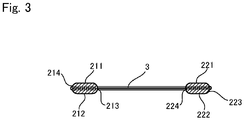
- FIG. 3 is a cross-sectional view taken along line B-B in FIG. 1 .
- the left side in FIG. 1 may also be referred to as a front end side
- the right side may also be referred to as a rear end side.
- the directions of the present invention are not limited to the thus-determined directions.
- this interdental cleaning tool includes a cleaning tool main body 10 made of a resin, and a thread member 3 that is attached to the cleaning tool main body 10 and is used to remove interdental dental plaque.
- the cleaning tool main body 10 includes a handle portion 1 extending in a rod-like manner, and two supporting pieces 21 and 22 protrude from this handle portion 1 with a predetermined interval.
- the supporting piece protruding from the end portion of the handle portion 1 is referred to as a "first supporting piece 21”
- the supporting piece extending in parallel with the first supporting piece 21 is referred to as a "second supporting piece 22".
- the above-described thread member 3 spans between the supporting pieces 21 and 22, and extends in parallel with the handle portion 1.
- the two end portions of the thread member 3 are respectively coupled to the supporting pieces 21 and 22.
- the members will be described in detail.
- Various materials can be used to form the supporting pieces 21 and 22 and the handle portion 1.
- resin materials such as polystyrene, polyethylene, polypropylene, and polyethylene terephthalate.
- polystyrene typically has a small shrinkage percentage and high rigidity, and is thus suitable for a case where the thread member 3 spans between the supporting pieces 21 and 22.
- a circular recessed portion 25 is formed near the base end portion of the second supporting piece 22 in order to prevent a trace of the gate from protruding from the surface of the handle portion 1. It is sufficient that the diameter of the recessed portion 25 is set to be larger than the diameter of the contact trace of the gate. In a case where a valve gate-type mold 100 is used as described later, an annular protruding portion, which is a contact trace of the valve gate, may be formed inside the recessed portion 25.
- the diameter of the contact trace of the gate is typically 0.8 to 4 mm, and preferably 0.8 to 2.5 mm.
- the supporting pieces 21 and 22 are formed in a plate shape.
- the surfaces of the supporting pieces 21 and 22 are named as follows: the surfaces on the front side of the plane of FIG. 1 are respectively referred to as “front surfaces 211 and 221”, the surfaces on the rear side of the plane of FIG. 1 are respectively referred to as “rear surfaces 212 and 222", the surfaces on the right side of FIG. 1 are respectively referred to as “right surfaces 213 and 223”, and the surfaces on the left side are respectively referred to as “left surfaces 214 and 224".
- positions through which the thread member 3 passes are located near the leading ends of the supporting pieces 21 and 22. That is, the distance L between such positions and the leading ends of the supporting pieces 21 and 22 is preferably 2.9 mm or more and 4 mm or less, and more preferably 2.9 mm or more and 3.2 mm or less.
- the thread member 3 is constituted by a single multifilament or a bundle of multifilaments 31.
- a single multifilament or a bundle of multifilaments 31 is obtained by twisting together a plurality of monofilaments made of nylon.
- the coefficient of friction of nylon is larger than that of polyethylene and the like, and therefore, use of nylon has the advantage that a dental plaque scraping effect is improved.
- the multifilament 31 may be a bundle of monofilaments in which the monofilaments are not twisted together.
- each multifilament 31 is not particularly limited, but is preferably 100 to 250 deniers, and more preferably 100 to 160 deniers, for example. If the thickness is smaller than 100 deniers, there is a risk that the multifilaments 31 will come out of the supporting pieces 21 and 22. If the thickness is larger than 250 deniers, it may be difficult to insert the multifilaments 31 between teeth.
- the number of multifilaments 31 included in the thread member 3 is not particularly limited, but is preferably 3 to 7, for example. If the number of multifilaments 31 is 3 or more, a dental plaque scraping effect will be improved, whereas if the number of multifilaments 31 is 7 or less, it will be easy to insert the thread member 3 between teeth, and the handleability will be improved, thus making it possible to improve the dental plaque scraping effect.
- the number of monofilaments included in the multifilament 31 is preferably 15 to 120, more preferably 30 to 100, and particularly preferably 50 to 100.
- the maximum twist number of the multifilament 31 per meter is 500 or less. Specifically, the maximum twist number is preferably 300 or less, more preferably 200 or less, and particularly preferably 170 or less. The following is the reason for this. That is, if the twist number of the multifilament 31 is too large, the multifilament will be too thin, and therefore, a cleaning effect may be hard to obtain.
- the minimum twist number of the multifilament 31 per meter is not particularly limited, and the multifilament 31 may also include monofilaments that are not twisted together.
- the minimum twist number of the multifilament 31 is preferably 50 or more, for example, from the viewpoint that the monofilaments are less likely to come apart and spread out during the production of the interdental cleaning tool, thus making it easy to produce the interdental cleaning tool.
- FIG. 1 two end portions of the thread member 3 respectively pass through the supporting pieces 21 and 22. Specifically, the left end portion of the thread member 3 passes through the right surface 213 of the first supporting piece 21 and protrudes from the left surface 214. Similarly, the right end portion of the thread member 3 passes through the left surface 224 of the second supporting piece 22 and protrudes from the right surface 223.
- This interdental cleaning tool is produced through injection molding. First, a mold will be described.
- FIG. 4 is a plan view of a stationary mold of the mold
- FIG. 5 is a cross-sectional view of the mold shown in FIG. 4 taken along line C-C. It should be noted that both the stationary mold and a movable mold are shown in FIG. 5 .
- a mold 100 is used in a so-called hot runner method, and includes a stationary mold 100a and a movable mold 100b.
- a plurality of (two in this embodiment) first cavities 101 for molding a plurality of cleaning tool main bodies 10 are formed in a surface of each of the stationary mold 100a and the movable mold 100b, the surfaces being brought into contact with each other.
- the plurality of first cavities 101 corresponding to the cleaning tool main bodies 10 are arranged such that portions (referred to as “handle cavities 106" hereinafter) corresponding to the handle portions 1 of the cleaning tool main bodies 10 are lined up in a linear manner.
- a single thread member 3 is arranged extending in the mold 100. This thread member 3 is arranged so as to span between portions (referred to as “supporting piece cavities 105" hereinafter) corresponding to the supporting pieces 21 and 22 in the first cavities 101. Accordingly, a single thread member 3 is arranged so as to connect the four supporting piece cavities 105. In the mold 100, such a position at which the thread member 3 is arranged is referred to as a "thread member position". It should be noted that, although not shown in the diagrams, grooves in which the thread member 3 is to be arranged are formed at portions of the thread member position excluding portions of the thread member position located in the first cavities 101 of the movable mold 100b.
- the stationary mold 100a is provided with gates 110 used to supply a molten resin material to the cavities 101, and valves 120 that can be opened and closed are attached to the gates 110. More specifically, each of the gates 110 is formed to have a circular cross section, and includes a leading end region 111 whose diameter decreases toward the cavity 101.
- the valve 120 having a columnar shape is provided so as to close the opening of the leading end region 111.
- Each of the valves 120 can be moved back and forward in the direction in which the gate 110 extends, and the gate 110 is closed when the leading end of the valve 120 reaches the opening of the leading end region 111.
- the resin material flows into the cavity 101 through a gap between the outer circumferential surface of the valve 120 and the inner wall surface of the leading end region 111.
- the movable mold 100b is configured so as to be brought close to and moved away from the stationary mold 100a.
- the resin material is poured into the cavities 101 while the movable mold 100b is in contact with the stationary mold 100a. After a predetermined cooling time has elapsed, the movable mold 100b is moved away from the stationary mold 100a.
- a support 6 is to be arranged between the stationary mold 100a and the movable mold 100b.
- This support 6 includes a main body portion 61 extending in a plate-like manner, and four pick-up members 621 and 622 that are respectively provided at the two ends of the main body portion 61 and positions corresponding to the first cavities 101 between the two ends of the main body portion 61.
- the pick-up members provided at the two ends of the main body portion 61 are referred to as "first pick-up members 621”
- the pick-up members provided at the positions corresponding to the first cavities 101 are referred to as "second pick-up members 622”.
- a robot arm (not shown) is attached to the vicinity of the center of the main body portion 61, and can be used to move the support 6.
- Each of the first pick-up members 621 is arranged on an end portion side with respect to the first cavities 101 in the mold 100.
- the first pick-up members 621 pick up portions of the thread member 3 located outside the cleaning tool main bodies 10, and the second pick-up members 622 respectively pick up the cleaning tool main bodies 10.
- the configurations of the pick-up members 62 there is no particular limitation on the configurations of the pick-up members 62 as long as the pick-up members 62 can pick up the thread member 3 and the cleaning tool main bodies 10.
- the pick-up members can be configured to pick up the thread member 3 and the cleaning tool main bodies 10 through the suction of air.
- means for holding the thread member 3 may be used instead of the first pick-up members 621, and there is no particular limitation on the means as long as they can reliably fix the thread member 3 and move the thread member 3 together with the support 6.
- Using means for holding the thread member 3 instead of the first pick-up members 621 is preferable to causing the first pick-up members 621 to pick up the thread member 3 because it is easy to hold the thread member 3 and move the cleaning tool main bodies 10 from the first cavities 101 of the movable mold 100b.
- the interdental cleaning tool producing method will be described with reference to FIGS. 7 to 11 .
- the movable mold 100b is moved away from the stationary mold 100a, and a gap is formed between the stationary mold 100a and the movable mold 100b.
- the thread member 3 delivered from a delivery apparatus (not shown) arranged below the mold 100 is arranged between the stationary mold 100a and the movable mold 100b, and a portion of the thread member 3 located above the mold 100 and a portion of the thread member 3 located below the mold 100 are fixed using holding members 7 to arrange the thread member 3 at the above-described thread member position.
- the movable mold 100b is brought into contact with the stationary mold 100a, and the thread member 3 is thus sandwiched therebetween.
- the openings of the gates 110 are opened by moving back the valves 120, and a molten resin material is poured into the cavities 101.
- the valves 120 are moved to close the openings of the gates 110. Then, the resin material is cooled for a predetermined period of time, and the molding of the cleaning tool main bodies 10 is thus finished.
- the thread member 3 is embedded in the supporting pieces 21 and 22 and is integrated therewith, and the plurality of cleaning tool main bodies 10 are coupled by the single thread member 3.
- the movable mold 100b is moved away from the stationary mold 100a.
- the molded cleaning tool main bodies 10 are located on the movable mold 100b.
- a robot arm is used to arrange the support 6 between the movable mold 100b and the stationary mold 100a, and the pick-up members 621 and 622 are brought into contact with the thread member 3 and the cleaning tool main bodies 10.
- the cleaning tool main bodies 10 are moved away from the first cavities 101 of the movable mold 100b by ejector pins (not shown) protruding from the inside of the movable mold while the support 6 is moved away from the movable mold 100b. In this state, a plurality of cleaning tool main bodies 10 are attached to the single thread member 3 between the first pick-up members 621. Subsequently, as shown in FIG. 10 , the fixing of the thread member 3 by the holding members 7 located above and below the mold 100 is released, and the support 6 is moved upward from the mold 100 in the state in which the support 6 picks up the thread member 3 and the cleaning tool main bodies 10.
- the thread member 3 is cut at a position between the holding member 7 located above the mold 100 and the first pick-up member 621 located below the cleaning tool main bodies 10 using a cutting means 75 such as scissors.
- the thread member 3 and the cleaning tool main bodies 10 are arranged on an examination table 8. Thereafter, as shown in FIG. 12 , the pick-up members 621 and 622 are removed from the thread member 3 and the cleaning tool main bodies 10, and then the support 6 is moved to the vicinity of the mold 100. Meanwhile, the mold 100 is used to mold the next cleaning tool main bodies 10 through the above-described procedures shown in FIGS. 7 to 11 .
- the thread member 3 is cut at a position located near the left surface 214 of the first supporting piece 21 of the cleaning tool main body 10 and a position located near the right surface 223 of the second supporting piece 22 of the cleaning tool main body 10 using a Thomson blade.
- the thread member 3 can be burned off using a flame or a heated-edge tool, or through radiation of heat rays such as far-infrared rays, or through electric discharge.
- a plurality of interdental cleaning tools in which the thread member 3 and the cleaning tool main body 10 are integrated together are thus formed.
- FIG. 14 is a plan view of a stationary mold of a mold according to this embodiment.
- pressing members 108 that are formed in one piece with the stationary mold 100a and protrude toward a movable mold 100b side are arranged at positions located outside supporting piece cavities 105 (that is, positions located on sides opposite to a portion between the supporting piece cavities 105).
- Cutters 85 are respectively arranged outside the pressing members 108.
- the pressing members 108 press the thread member 3 against the stationary mold 100a when the stationary mold 100a and the movable mold 100b are brought into contact with each other.
- the cutters 85 cut the thread member 3 at ends of portions pressed by the pressing members 108 when the stationary mold 100a and the movable mold 100b are brought into contact with each other.
- suction ports are formed in portions 107 that are parts of the portion on which the thread member 3 is arranged excluding the portions located between the supporting piece cavities 105.
- a support 6 is not provided with first pick-up members 621 but is provided with only second pick-up members 622 unlike the first embodiment.
- the movable mold 100b is moved away from the stationary mold 100a, and a gap is formed between the stationary mold 100a and the movable mold 100b.
- the thread member 3 delivered from a delivery apparatus (not shown) arranged below the mold 100 is arranged between the stationary mold 100a and the movable mold 100b, and a portion of the thread member 3 located above the mold 100 and a portion of the thread member 3 located below the mold 100 are fixed using holding members 7 to arrange the thread member 3 at the above-described thread member position.
- the movable mold 100b is brought into contact with the stationary mold 100a, and the thread member 3 is thus sandwiched therebetween.
- portions of the thread member 3 located outside the supporting piece cavities 105 are pressed by the pressing members 108.
- two ends of the cut thread member 3 are located outside each supporting piece cavity 105 and are pressed by the pressing members 108, and therefore, the thread member 3 does not come loose and predetermined tension is maintained.
- a resin material is poured in the same manner as mentioned above, and the resin material is cooled for a predetermined period of time.
- the thread member 3 is cut at positions located outside the pressing members 108 using the cutters 85, and the molding of cleaning tool main bodies 10 is thus finished.
- the thread member 3 is embedded in the supporting pieces 21 and 22 and is integrated therewith, and the cleaning tool main bodies 10 are completed inside the mold 100.
- the pressing members 108 are provided in this embodiment, they need not be provided, and only the cutters 85 may be provided, for example. Moreover, retractable pressing members 108 may also be provided in the mold.
- a robot arm is used to arrange the support 6 between the movable mold 100b and the stationary mold 100a.
- the cleaning tool main bodies 10 are moved away from the first cavities 101 of the movable mold 100b by ejector pins (not shown) protruding from the inside of the movable mold 100b while the support 6 is moved away from the movable mold 100b.
- the robot arm is moved to arrange the cleaning tool main bodies 10 on an examination table 8, and the aesthetic properties are checked in the same manner as in the first embodiment.
- the thread member 3 is cut inside the mold 100, and therefore, a step of cutting the thread member 3 becomes unnecessary in a later process.
- the support 6 need not pick up the thread member 3 and need only pick up the cleaning tool main bodies 10, thus making it possible to simplify the configuration of the support 6.
- suction of the pieces that are cut from the thread member 3 can be performed in the mold 100, and therefore, a step of disposing of the pieces that are cut from the thread member 3 becomes unnecessary in a later process.
- the cavities 101 are filled with the resin material using a hot runner method, and therefore, a large number of runner portions that are difficult to recycle due to difficulty in separating the thread member 3 fixed thereto are not formed unlike a typical cold runner method. Accordingly, the amount of resin material to be disposed of can be significantly reduced. As a result, the production cost can be significantly reduced. Moreover, additional time to cool the runner portions is needed in the case of the cold runner method, but with the hot runner method, such time is not needed, thus making it possible to improve the production cycle.
- suction of the pieces of the thread member 3 is performed in the mold 100, and the pieces are then disposed of, but the following configuration can also be employed. That is, as shown in FIG. 16 , disposal member cavities 109 for molding disposal members to be used to dispose of pieces of the thread member 3 are formed between the first cavities 101. These disposal member cavities 109 are formed at positions at which unnecessary pieces of the thread member 3 are arranged. With this configuration, when the disposal member cavities 109 are filled with the resin material, disposal members that are integrated with the piece of the thread member 3 are formed.
- the disposal members are moved away from the movable mold 100b together with the pieces of the thread member 3. Then, the disposal members and the pieces of the thread member 3 fall out of the mold 100 and are then disposed of. Accordingly, the suction ports through which suction of the pieces that are cut from the thread member 3 as described above become unnecessary. Subsequent steps are the same as those described above.
- the size, shape, and thickness of the disposal members are not particularly limited as long as they can be integrated with a piece of the thread member 3 and removed from the mold 100. However, it is preferable that the thickness and volume of the disposal members are smaller than that of the cleaning tool main bodies 10 from the viewpoint of reducing the amount of resin to be disposed of and reducing the cooling time.
- the thickness of the disposal members can be set to 0.1 to 2 mm, and is preferably 0.1 to 1 mm.
- the volume of the disposal members can be set to 0.1 to 1 cm 3 , and is preferably 0.1 to 0.5 cm 3 .
- FIG. 17 is a plan view of a stationary mold of a mold
- FIG. 18 is a cross-sectional view of the mold shown in FIG. 17 taken along line D-D. It should be noted that both the stationary mold and a movable mold are shown in FIG. 18 .
- a plurality of (two in this embodiment) first cavities 101 that are the same as those in the first embodiment, and two second cavities 102 for molding removal members 50, which will be described later, are formed on a surface of each of a stationary mold 100a and a movable mold 100b, the surfaces being brought into contact with each other.
- the plurality of first cavities 101 corresponding to cleaning tool main bodies 10 have the same configurations as those in the first embodiment, but the third embodiment is different from the first embodiment in that the removal members 50 are molded at the two end portions of a thread member 3. That is, as described above, in this mold 100, the second cavities 102 for molding the removal members 50 are formed at positions corresponding to the two end portions of the thread member 3 arranged at a thread member position.
- the removal members 50 are formed into a thin plate having a rectangular shape in a plan view, and are molded such that the thread member 3 passes through the inside of the removal members 50.
- a circular recessed portion (not shown) is formed on the surface of each removal member 50, and this recessed portion corresponds to a gate 110 of the mold 100.
- the thickness of the removal members 50 (e.g., the thickness of the removal members 50 in a left-right direction in FIG. 21 ) is smaller than that of the cleaning tool main bodies 10.
- the thickness of the removal members 50 can be set to 0.1 to 2 mm, for example, and is preferably 0.1 to 1 mm.
- the volume of the removal members 50 is smaller than that of the cleaning tool main bodies 10.
- the volume of the removal members 50 can be set to 0.1 to 1 cm 3 for example, and is preferably 0.1 to 0.5 cm 3 .
- a support 6 used in this embodiment has the same configuration as that of the support 6 of the first embodiment, but is different from that of the first embodiment in that first pick-up members 621 are configured to pick up the removal members 50.
- the pick-up members 621 and 622 are respectively configured to pick up the removal members 50 and the cleaning tool main bodies 10 in order to stably move the cleaning tool main bodies 10 away from the first cavities 101 of the movable mold 100b, but only the first pick-up members 621 may be provided such that the support 6 can pick up only the removal members 50.
- the interdental cleaning tool producing method will be described with reference to FIGS. 20 to 24 .
- the thread member 3 is arranged between the movable mold 100b and the stationary mold 100a, and a portion of the thread member 3 located above the mold 100 and a portion of the thread member 3 located below the mold 100 are fixed using holding members 7, in the same manner as in the first embodiment.
- the movable mold 100b is brought into contact with the stationary mold 100a, and the thread member 3 is thus sandwiched therebetween.
- a molten resin material is poured into the cavities 101 and 102 in the same manner as in the first embodiment, and the resin material is cooled for a predetermined period of time. The molding of the removal members 50 and the cleaning tool main bodies 10 is thus finished.
- the thread member 3 is integrated with the supporting pieces 21 and 22, and the plurality of cleaning tool main bodies 10 are coupled by the single thread member 3.
- the removal members 50 are respectively fixed to the two ends of the thread member 3 and integrated with the thread member 3.
- the movable mold 100b is moved away from the stationary mold 100a.
- the molded removal members 50 and the molded cleaning tool main bodies 10 are located on the movable mold 100b.
- the pick-up members 621 and 622 are caused to pick up the removal members 50 and the cleaning tool main bodies 10.
- the removal members 50 and the cleaning tool main bodies 10 are moved away from the first cavities 101 and the second cavities 102 of the movable mold 100b by ejector pins (not shown) protruding from the inside of the movable mold while the support 6 is moved away from the movable mold 100b.
- the removal members 50 and the cleaning tool main bodies 10 are arranged on an examination table 8. Thereafter, as shown in FIG. 12 , the pick-up members 621 and 622 are removed from the removal members 50 and the cleaning tool main bodies 10, and then the support 6 is moved to the vicinity of the mold 100, in the same manner as in the first embodiment.
- the aesthetic properties of the cleaning tool main bodies 10 and the thread member 3 are checked.
- the thread member 3 and the plurality of cleaning tool main bodies 10 are lined up between the two removal members 50, thus making it easy to check them.
- the thread member is cut in the same manner as in the first embodiment. A plurality of interdental cleaning tools in which the thread member 3 and the cleaning tool main body 10 are integrated together are thus formed.
- the thread member 3 is a bundle of multifilaments 31, but the number of multifilaments 31 may also be one.
- the two end portions of the thread member 3 are respectively fixed to the supporting pieces 21 and 22, but the two end portions of each multifilament 31 are melted to form masses at the two end portions of the thread member 3 in order to prevent the thread member 3 from being dislodged.
- various types of welding using ultrasonic waves and the like can be performed as the melting method.
- the thread member 3 may be formed by merely bundling a plurality of multifilaments 31, or by twisting the plurality of multifilaments 31 from the viewpoint of suppressing the separation of the multifilaments 31 from each other when arranging the thread member 3 at the thread member position.
- the shape of the cleaning tool main body 10 is not limited to the above-described thickness, and can be changed as appropriate.
- the removal members 50 are provided at the two ends of the thread member 3, but a removal member 50 can also be provided at only one end of the thread member 3. Even in this case, it is sufficient that the one removal member 50 and the cleaning tool main bodies 10 are pulled and removed from the mold 100, and then the thread member 3 and the cleaning tool main bodies 10 hang from the removal member 50 and moved.
- the size and shape of the removal members 50 there is no particular limitation on the size and shape of the removal members 50. It is preferable that the thickness and volume thereof are smaller than those of the cleaning tool main bodies 10, but there is no limitation thereto. Those of a slightly larger size and volume are also allowable.
- valve gate system is employed for the mold 100, but an open gate system can also be employed.
- a single thread member 3 is arranged in a single mold 100, and the removal members 50 and the cleaning tool main bodies 10 that are lined up in one row are molded.
- a configuration can also be employed in which a plurality of thread members 3 are arranged and removal members 50 and cleaning tool main bodies 10 that are lined up in a plurality of rows are molded.
Landscapes
- Engineering & Computer Science (AREA)
- Mechanical Engineering (AREA)
- Health & Medical Sciences (AREA)
- Manufacturing & Machinery (AREA)
- Dentistry (AREA)
- Epidemiology (AREA)
- Life Sciences & Earth Sciences (AREA)
- Animal Behavior & Ethology (AREA)
- General Health & Medical Sciences (AREA)
- Public Health (AREA)
- Veterinary Medicine (AREA)
- Moulds For Moulding Plastics Or The Like (AREA)
Abstract
Description
- The present invention relates to an interdental cleaning tool producing method.
- Conventionally, various types of interdental cleaning tools for removing dental plaque stuck between teeth have been proposed. For example, Patent Literature 1 proposes an interdental cleaning tool including: a cleaning tool main body made of a resin that has supporting pieces that are arranged with a predetermined interval and a handle portion that couples the supporting pieces and can be held in a hand; and a thread member called floss that spans between the supporting pieces. Such an interdental cleaning tool is molded as follows. That is, the thread member is arranged in a mold, and then the cleaning tool main body is molded through injection molding. At this time, molding is performed such that a plurality of cleaning tool main bodies are fixed to a single thread member. After the molding is finished, the thread member is cut, and the interdental cleaning tool is thus completed.
- Patent Literature 1: Japanese Registered Utility Model No.
3066189 - In the producing method as mentioned above, a cold runner method is employed, and not only the cleaning tool main body but also a large number of runner portions around the cleaning tool main body are molded in a state in which the thread member is fixed. Therefore, when the thread member is cut after the molding is finished, the runner portions fixed to the thread member are also cut from the cleaning tool main body together with the thread member. Since the runner portions are formed of the same resin material as that for forming the cleaning tool main body, it is conceivable to recycle the runner portions to reduce costs. However, despite the generation of such a large number of runner portions, it is difficult to recycle the runner portions as the resin material because the thread member is fixed to the runner portions and needs to be separated from the runner portions in order to be able to recycle the runner portions.
- The present invention was made in order to solve this problem, and an object thereof is to provide an interdental cleaning tool producing method that enables cost reduction.
- An interdental cleaning tool producing method according to the present invention includes: a first step of preparing a mold provided with at least one first cavity for molding a cleaning tool main body including two supporting pieces that are arranged with a predetermined interval and a handle portion that couples the two supporting pieces and can be held in a hand, the mold being configured such that at least one thread member to span between the two supporting pieces can be arranged in the mold; a second step of arranging the thread member in the mold; a third step of filling the first cavity with a resin material via a gate provided in the mold using a hot runner method; and a fourth step of removing the thread member and the cleaning tool main body fixed to the thread member from the mold.
- With this configuration, the cavity is filled with the resin material using a hot runner method, and therefore, a large number of runner portions are not formed unlike a typical cold runner method. If a thread member is fixed to a resin material, the resin material will be disposed of due to difficulty in removing the thread member. However, with the above-described configuration, the amount of resin material to be disposed of can be significantly reduced. As a result, the production cost can be significantly reduced. Moreover, additional time to cool the runner portions is needed in the case of the cold runner method, but with the present invention, such time is not needed, thus making it possible to improve the production cycle.
- In the above-mentioned interdental cleaning tool producing method, the thread member and the cleaning tool main body can be removed from the mold using various methods. For example, a configuration can be employed in which, in the fourth step, the cleaning tool main body fixed to the thread member is removed from the mold together with the thread member by moving at least the thread member from the mold.
- With this configuration, at least one cleaning tool main body is attached to a single thread member, thus making it easy to remove the cleaning tool main body fixed to the thread member from the mold together with the thread member by moving at least the thread member from the mold. Therefore, by also employing the above-described hot runner method, substantially no resin material is disposed of, thus making it possible to reduce the cost.
- Alternatively, a configuration can be employed in which the interdental cleaning tool producing method further includes a step of cutting the thread member at positions outside the supporting pieces of the cleaning main body inside the mold prior to the fourth step.
- With this configuration, the thread member can be cut inside the mold, and therefore, a subsequent step of cutting the thread member becomes unnecessary.
- Alternatively, a configuration can be employed in which the mold is further provided with a second cavity for molding a removal member on at least one end portion side of the thread member; in the third step, the first cavity and the second cavity are filled with the resin material using a hot runner method; and in the fourth step, the thread member and the cleaning tool main body fixed to the thread member are removed from the mold together with the removal member by moving the removal member from the mold.
- With this configuration, at least one cleaning tool main body is attached to a single thread member, and the removal member is molded at at least one of the end portions of the thread member, thus making it easy to remove the thread member and the cleaning tool main body fixed to the thread member from the mold together with the removal member by moving at least the removal member from the mold. Such a removal member need only have a size that allows at least the thread member to be fixed to the removal member, and therefore, the removal member need not be formed in a size similar to the sizes of the runner portions of the conventional example. Since the thread member is fixed to this removal member, it is difficult to recycle the removal member. However, the size of the removal member can be reduced to the minimum required size, and therefore, the amount of resin material to be disposed of can be suppressed to the minimum even if the removal member is disposed of. Accordingly, as a result, it is possible to reduce the cost.
- Moreover, the thread member and the cleaning tool main body can be moved to a desired position by moving the removal member, thus making it possible to improve production efficiency.
- When the removal member is used in the above-mentioned interdental cleaning tool producing method, the thickness of the removal member can be set to be smaller than or equal to the thickness of the cleaning tool main body. Accordingly, the removal member can be cooled in less time than the time required to cool the cleaning tool main body, thus making it possible to prevent an increase in the production cycle time.
- When the removal member is used in the above-mentioned interdental cleaning tool producing method, the volume of the removal member can be set to be smaller than or equal to the volume of the cleaning tool main body. Accordingly, the removal member can be cooled in less time than the time required to cool the cleaning tool main body, thus making it possible to prevent an increase in the production cycle time.
- In the method in which the cleaning tool main body fixed to the thread member is removed from the mold together with the thread member by moving the thread member from the mold, and the method in which the removal member is used, out of the above-mentioned interdental cleaning tool producing methods, in the fourth step, a new thread member for the subsequent molding process can be arranged in the mold after the thread member to which the cleaning tool main body is fixed is moved in a direction in which the thread member extends. Accordingly, the interdental cleaning tool can be efficiently molded.
- When the removal member is used in the above-mentioned interdental cleaning tool producing method, a configuration can be employed in which the second cavities are formed at positions corresponding to the two ends of the thread member, the first cavity and second cavities are filled with the resin material in the third step, the thread member and at least one cleaning tool main body fixed to the thread member are moved from the mold in the fourth step by moving, from the mold, the removal members provided at the two ends of the thread member with a constant distance being maintained between the removal members, and a fifth step is further provided in which the removal members, the thread member, and at least one cleaning tool main body fixed to the thread member are arranged on an examination table and then are checked.
- Accordingly, the cleaning tool main body fixed to the thread member can be moved with the thread member being extended between the removal members. Arranging the thread member and the cleaning tool main body on an examination table as they are makes it possible to arrange them in a state in which they are lined up, and therefore, they can be easily and efficiently checked.
- In the above-mentioned interdental cleaning tool producing methods, a valve gate system in which the gate is opened/closed using a valve or an open gate system in which no valves are included may be employed. It should be noted that, when the valve gate system is employed, the cleaning tool main body is cut off from at the gate by a valve blocking the resin material, thus making it possible to prevent the resin material from extending from the cleaning tool main body like string. In particular, the interdental cleaning tool according to the present invention is used in the oral cavity, and therefore, it is not desired that the resin material extends like string.
- The interdental cleaning tool producing method according to the present invention enables cost reduction.
-
-
FIG. 1 is a front view of an interdental cleaning tool according to a first embodiment of the present invention. -
FIG. 2 is a cross-sectional view taken along line A-A inFIG. 1 . -
FIG. 3 is a cross-sectional view taken along line B-B inFIG. 1 . -
FIG. 4 is a schematic plan view showing a stationary mold of a mold for producing the interdental cleaning tool shown inFIG. 1 . -
FIG. 5 is a cross-sectional view taken along line C-C inFIG. 4 . -
FIG. 6 is a diagram showing a state in which a support is arranged between the stationary mold and a movable mold of the mold inFIG. 4 . -
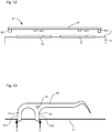
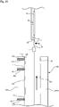
FIG. 7 is a diagram illustrating a method for producing the interdental cleaning tool shown inFIG. 1 . -
FIG. 8 is a diagram illustrating the method for producing the interdental cleaning tool shown inFIG. 1 . -
FIG. 9 is a diagram illustrating the method for producing the interdental cleaning tool shown inFIG. 1 . -
FIG. 10 is a diagram illustrating the method for producing the interdental cleaning tool shown inFIG. 1 . -
FIG. 11 is a diagram illustrating the method for producing the interdental cleaning tool shown inFIG. 1 . -
FIG. 12 is a diagram illustrating the method for producing the interdental cleaning tool shown inFIG. 1 . -
FIG. 13 is a diagram illustrating the method for producing the interdental cleaning tool shown inFIG. 1 . -
FIG. 14 is a schematic plan view showing a stationary mold of a mold for producing an interdental cleaning tool according to a second embodiment of the present invention. -
FIG. 15 is a diagram illustrating a method for producing the interdental cleaning tool according to the second embodiment. -
FIG. 16 is a plan view showing another example of the stationary mold shown inFIG. 14 . -
FIG. 17 is a schematic plan view showing a stationary mold of a mold for producing an interdental cleaning tool according to a third embodiment of the present invention. -
FIG. 18 is a cross-sectional view taken along line D-D inFIG. 17 . -
FIG. 19 is a diagram showing a state in which a support is arranged between the stationary mold and a movable mold of the mold inFIG. 18 . -
FIG. 20 is a diagram illustrating a method for producing the interdental cleaning tool according to the third embodiment. -
FIG. 21 is a diagram illustrating the method for producing the interdental cleaning tool according to the third embodiment. -
FIG. 22 is a diagram illustrating the method for producing the interdental cleaning tool according to the third embodiment. -
FIG. 23 is a diagram illustrating the method for producing the interdental cleaning tool according to the third embodiment. -
FIG. 24 is a diagram illustrating the method for producing the interdental cleaning tool according to the third embodiment. - Hereinafter, a first embodiment of an interdental cleaning tool producing method according to the present invention will be described with reference to the drawings. In the following description, first, the outline of an interdental cleaning tool will be described, and then a method for producing this interdental cleaning tool will be described.
- Hereinafter, the outline of an interdental cleaning tool will be described with reference to
FIGS. 1 to 3 .FIG. 1 is a front view of an interdental cleaning tool according to this embodiment,FIG. 2 is a cross-sectional view taken along line A-A inFIG. 1 , andFIG. 3 is a cross-sectional view taken along line B-B inFIG. 1 . It should be noted that the following description will be made based on the directions in the diagram shown inFIG. 1 for the sake of ease of description. Regarding a handle portion, the left side inFIG. 1 may also be referred to as a front end side, and the right side may also be referred to as a rear end side. However, the directions of the present invention are not limited to the thus-determined directions. - As shown in
FIG. 1 , this interdental cleaning tool includes a cleaning toolmain body 10 made of a resin, and athread member 3 that is attached to the cleaning toolmain body 10 and is used to remove interdental dental plaque. The cleaning toolmain body 10 includes a handle portion 1 extending in a rod-like manner, and two supportingpieces piece 21", and the supporting piece extending in parallel with the first supportingpiece 21 is referred to as a "second supportingpiece 22". The above-describedthread member 3 spans between the supportingpieces thread member 3 are respectively coupled to the supportingpieces - Various materials can be used to form the supporting
pieces thread member 3 spans between the supportingpieces - In the cleaning tool
main body 10, a circular recessedportion 25 is formed near the base end portion of the second supportingpiece 22 in order to prevent a trace of the gate from protruding from the surface of the handle portion 1. It is sufficient that the diameter of the recessedportion 25 is set to be larger than the diameter of the contact trace of the gate. In a case where a valve gate-type mold 100 is used as described later, an annular protruding portion, which is a contact trace of the valve gate, may be formed inside the recessedportion 25. The diameter of the contact trace of the gate is typically 0.8 to 4 mm, and preferably 0.8 to 2.5 mm. - The supporting
pieces pieces FIG. 1 are respectively referred to as "front surfaces FIG. 1 are respectively referred to as "rear surfaces FIG. 1 are respectively referred to as "right surfaces surfaces pieces thread member 3 passes are located near the leading ends of the supportingpieces pieces - Next, the
thread member 3 will be described. Thethread member 3 is constituted by a single multifilament or a bundle ofmultifilaments 31. Hereinafter, in particular, a case where a plurality ofmultifilaments 31 are used to form the thread member will be described. Each of themultifilaments 31 is obtained by twisting together a plurality of monofilaments made of nylon. The coefficient of friction of nylon is larger than that of polyethylene and the like, and therefore, use of nylon has the advantage that a dental plaque scraping effect is improved. It should be noted that the multifilament 31 may be a bundle of monofilaments in which the monofilaments are not twisted together. - The thickness of each multifilament 31 is not particularly limited, but is preferably 100 to 250 deniers, and more preferably 100 to 160 deniers, for example. If the thickness is smaller than 100 deniers, there is a risk that the
multifilaments 31 will come out of the supportingpieces multifilaments 31 between teeth. - The number of
multifilaments 31 included in thethread member 3 is not particularly limited, but is preferably 3 to 7, for example. If the number ofmultifilaments 31 is 3 or more, a dental plaque scraping effect will be improved, whereas if the number ofmultifilaments 31 is 7 or less, it will be easy to insert thethread member 3 between teeth, and the handleability will be improved, thus making it possible to improve the dental plaque scraping effect. - The number of monofilaments included in the multifilament 31 is preferably 15 to 120, more preferably 30 to 100, and particularly preferably 50 to 100.
- It is preferable that the maximum twist number of the multifilament 31 per meter is 500 or less. Specifically, the maximum twist number is preferably 300 or less, more preferably 200 or less, and particularly preferably 170 or less. The following is the reason for this. That is, if the twist number of the multifilament 31 is too large, the multifilament will be too thin, and therefore, a cleaning effect may be hard to obtain. The minimum twist number of the multifilament 31 per meter is not particularly limited, and the multifilament 31 may also include monofilaments that are not twisted together. However, the minimum twist number of the multifilament 31 is preferably 50 or more, for example, from the viewpoint that the monofilaments are less likely to come apart and spread out during the production of the interdental cleaning tool, thus making it easy to produce the interdental cleaning tool.
- Subsequently, a method for coupling the
thread member 3 to the supportingpieces FIG. 1 , two end portions of thethread member 3 respectively pass through the supportingpieces thread member 3 passes through theright surface 213 of the first supportingpiece 21 and protrudes from theleft surface 214. Similarly, the right end portion of thethread member 3 passes through theleft surface 224 of the second supportingpiece 22 and protrudes from theright surface 223. - Next, a method for producing the interdental cleaning tool configured as mentioned above will be described. This interdental cleaning tool is produced through injection molding. First, a mold will be described.
-
FIG. 4 is a plan view of a stationary mold of the mold, andFIG. 5 is a cross-sectional view of the mold shown inFIG. 4 taken along line C-C. It should be noted that both the stationary mold and a movable mold are shown inFIG. 5 . As shown inFIGS. 4 and5 , amold 100 is used in a so-called hot runner method, and includes astationary mold 100a and amovable mold 100b. A plurality of (two in this embodiment)first cavities 101 for molding a plurality of cleaning toolmain bodies 10 are formed in a surface of each of thestationary mold 100a and themovable mold 100b, the surfaces being brought into contact with each other. - The plurality of
first cavities 101 corresponding to the cleaning toolmain bodies 10 are arranged such that portions (referred to as "handlecavities 106" hereinafter) corresponding to the handle portions 1 of the cleaning toolmain bodies 10 are lined up in a linear manner. Asingle thread member 3 is arranged extending in themold 100. Thisthread member 3 is arranged so as to span between portions (referred to as "supportingpiece cavities 105" hereinafter) corresponding to the supportingpieces first cavities 101. Accordingly, asingle thread member 3 is arranged so as to connect the four supporting piece cavities 105. In themold 100, such a position at which thethread member 3 is arranged is referred to as a "thread member position". It should be noted that, although not shown in the diagrams, grooves in which thethread member 3 is to be arranged are formed at portions of the thread member position excluding portions of the thread member position located in thefirst cavities 101 of themovable mold 100b. - The
stationary mold 100a is provided withgates 110 used to supply a molten resin material to thecavities 101, andvalves 120 that can be opened and closed are attached to thegates 110. More specifically, each of thegates 110 is formed to have a circular cross section, and includes aleading end region 111 whose diameter decreases toward thecavity 101. Thevalve 120 having a columnar shape is provided so as to close the opening of theleading end region 111. Each of thevalves 120 can be moved back and forward in the direction in which thegate 110 extends, and thegate 110 is closed when the leading end of thevalve 120 reaches the opening of theleading end region 111. On the other hand, when thevalve 120 is moved back from the opening of theleading end region 111, the resin material flows into thecavity 101 through a gap between the outer circumferential surface of thevalve 120 and the inner wall surface of theleading end region 111. - The
movable mold 100b is configured so as to be brought close to and moved away from thestationary mold 100a. The resin material is poured into thecavities 101 while themovable mold 100b is in contact with thestationary mold 100a. After a predetermined cooling time has elapsed, themovable mold 100b is moved away from thestationary mold 100a. - As shown in
FIG. 6 , asupport 6 is to be arranged between thestationary mold 100a and themovable mold 100b. Thissupport 6 includes amain body portion 61 extending in a plate-like manner, and four pick-upmembers main body portion 61 and positions corresponding to thefirst cavities 101 between the two ends of themain body portion 61. Here, the pick-up members provided at the two ends of themain body portion 61 are referred to as "first pick-upmembers 621", and the pick-up members provided at the positions corresponding to thefirst cavities 101 are referred to as "second pick-upmembers 622". A robot arm (not shown) is attached to the vicinity of the center of themain body portion 61, and can be used to move thesupport 6. Each of the first pick-upmembers 621 is arranged on an end portion side with respect to thefirst cavities 101 in themold 100. When themain body portion 61 is arranged between thestationary mold 100a and themovable mold 100b, the first pick-upmembers 621 pick up portions of thethread member 3 located outside the cleaning toolmain bodies 10, and the second pick-upmembers 622 respectively pick up the cleaning toolmain bodies 10. There is no particular limitation on the configurations of the pick-upmembers 62 as long as the pick-upmembers 62 can pick up thethread member 3 and the cleaning toolmain bodies 10. For example, the pick-up members can be configured to pick up thethread member 3 and the cleaning toolmain bodies 10 through the suction of air. Regarding thethread member 3, means for holding thethread member 3 may be used instead of the first pick-upmembers 621, and there is no particular limitation on the means as long as they can reliably fix thethread member 3 and move thethread member 3 together with thesupport 6. Using means for holding thethread member 3 instead of the first pick-upmembers 621 is preferable to causing the first pick-upmembers 621 to pick up thethread member 3 because it is easy to hold thethread member 3 and move the cleaning toolmain bodies 10 from thefirst cavities 101 of themovable mold 100b. - Next, the interdental cleaning tool producing method will be described with reference to
FIGS. 7 to 11 . First, as shown inFIG. 7 , themovable mold 100b is moved away from thestationary mold 100a, and a gap is formed between thestationary mold 100a and themovable mold 100b. Next, thethread member 3 delivered from a delivery apparatus (not shown) arranged below themold 100 is arranged between thestationary mold 100a and themovable mold 100b, and a portion of thethread member 3 located above themold 100 and a portion of thethread member 3 located below themold 100 are fixed using holdingmembers 7 to arrange thethread member 3 at the above-described thread member position. - Subsequently, as shown in
FIG. 8 , themovable mold 100b is brought into contact with thestationary mold 100a, and thethread member 3 is thus sandwiched therebetween. Thereafter, the openings of thegates 110 are opened by moving back thevalves 120, and a molten resin material is poured into thecavities 101. After pouring of the resin material is finished, thevalves 120 are moved to close the openings of thegates 110. Then, the resin material is cooled for a predetermined period of time, and the molding of the cleaning toolmain bodies 10 is thus finished. - In this state, the
thread member 3 is embedded in the supportingpieces main bodies 10 are coupled by thesingle thread member 3. - Next, the
movable mold 100b is moved away from thestationary mold 100a. At this time, as shown inFIG. 9 , the molded cleaning toolmain bodies 10 are located on themovable mold 100b. Then, a robot arm is used to arrange thesupport 6 between themovable mold 100b and thestationary mold 100a, and the pick-upmembers thread member 3 and the cleaning toolmain bodies 10. After the pick-upmembers thread member 3 and the cleaning toolmain bodies 10, the cleaning toolmain bodies 10 are moved away from thefirst cavities 101 of themovable mold 100b by ejector pins (not shown) protruding from the inside of the movable mold while thesupport 6 is moved away from themovable mold 100b. In this state, a plurality of cleaning toolmain bodies 10 are attached to thesingle thread member 3 between the first pick-upmembers 621. Subsequently, as shown inFIG. 10 , the fixing of thethread member 3 by the holdingmembers 7 located above and below themold 100 is released, and thesupport 6 is moved upward from themold 100 in the state in which thesupport 6 picks up thethread member 3 and the cleaning toolmain bodies 10. Then, as shown inFIG. 11 , after thethread member 3 is fixed using the holdingmembers 7 again, thethread member 3 is cut at a position between the holdingmember 7 located above themold 100 and the first pick-upmember 621 located below the cleaning toolmain bodies 10 using a cutting means 75 such as scissors. - Subsequently, after the robot arm is moved and the orientation of the
support 6 is changed such that thesupport 6 extends horizontally, thethread member 3 and the cleaning toolmain bodies 10 are arranged on an examination table 8. Thereafter, as shown inFIG. 12 , the pick-upmembers thread member 3 and the cleaning toolmain bodies 10, and then thesupport 6 is moved to the vicinity of themold 100. Meanwhile, themold 100 is used to mold the next cleaning toolmain bodies 10 through the above-described procedures shown inFIGS. 7 to 11 . - On the examination table 8, the aesthetic properties of the cleaning tool
main bodies 10 and thethread member 3 are checked. At this time, thethread member 3 and the plurality of cleaning toolmain bodies 10 are lined up on the examination table 8, thus making it easy to check them. In the next step, as shown inFIG. 13 , thethread member 3 is cut at a position located near theleft surface 214 of the first supportingpiece 21 of the cleaning toolmain body 10 and a position located near theright surface 223 of the second supportingpiece 22 of the cleaning toolmain body 10 using a Thomson blade. Although thethread member 3 is cut using a blade in this embodiment, there is no particular limitation on a means 90 for cutting thethread member 3. For example, thethread member 3 can be burned off using a flame or a heated-edge tool, or through radiation of heat rays such as far-infrared rays, or through electric discharge. A plurality of interdental cleaning tools in which thethread member 3 and the cleaning toolmain body 10 are integrated together are thus formed. - As described above, with this embodiment, the following effects can be obtained.
- (1) A plurality of cleaning tool
main bodies 10 are attached to asingle thread member 3, thus making it easy to remove the cleaning toolmain bodies 10 fixed to thethread member 3 from themold 100 together with thethread member 3 by moving thethread member 3 from themold 100. Therefore, by also employing a hot runner method, which will be described next, substantially no resin material is wasted, thus making it possible to reduce the cost. - (2) With the producing method according to this embodiment, the
cavities 101 are filled with the resin material using a hot runner method, and therefore, a large number of runner portions that are difficult to recycle due to difficulty in separating thethread member 3 fixed thereto are not formed unlike a typical cold runner method. Accordingly, the amount of resin material to be disposed of can be significantly reduced. As a result, the production cost can be significantly reduced. Moreover, additional time to cool the runner portions is needed in the case of the cold runner method, but with the hot runner method, such time is not needed, thus making it possible to improve the production cycle. - (3) In the above-mentioned producing method, the valve gate system is employed. With this configuration, the cleaning tool
main bodies 10 are cut off from the gates by blocking the supply of the resin material using thevalves 120, thus making it possible to prevent the resin material from extending from the cleaning toolmain bodies 10 like string. - Next, a second embodiment of the interdental cleaning tool producing method according to the present invention will be described with reference to the drawings. In the following description, only the differences between the first embodiment and the second embodiment will be described, and therefore, the same components are denoted by the same reference numerals, and the descriptions of the redundant components will be omitted. Accordingly, unless otherwise stated, the configurations shown in the first embodiment can also be applied to the second embodiment. Moreover, in the following description, the diagrams used in the description of the first embodiment are also referred to.
-
FIG. 14 is a plan view of a stationary mold of a mold according to this embodiment. As shown inFIG. 14 , on astationary mold 100a of amold 100 according to this embodiment, pressingmembers 108 that are formed in one piece with thestationary mold 100a and protrude toward amovable mold 100b side are arranged at positions located outside supporting piece cavities 105 (that is, positions located on sides opposite to a portion between the supporting piece cavities 105).Cutters 85 are respectively arranged outside thepressing members 108. Thepressing members 108 press thethread member 3 against thestationary mold 100a when thestationary mold 100a and themovable mold 100b are brought into contact with each other. Thecutters 85 cut thethread member 3 at ends of portions pressed by thepressing members 108 when thestationary mold 100a and themovable mold 100b are brought into contact with each other. - In the
mold 100, suction ports (not shown) are formed inportions 107 that are parts of the portion on which thethread member 3 is arranged excluding the portions located between the supporting piece cavities 105. With this configuration, it is possible to perform suction of pieces that are cut from thethread member 3 and then separated from the cleaning toolmain bodies 10. - Furthermore, as shown in
FIG. 15 , asupport 6 is not provided with first pick-upmembers 621 but is provided with only second pick-upmembers 622 unlike the first embodiment. - When the above-described
mold 100 is used, molding is performed as described below. That is, as shown inFIG. 7 , themovable mold 100b is moved away from thestationary mold 100a, and a gap is formed between thestationary mold 100a and themovable mold 100b. Next, thethread member 3 delivered from a delivery apparatus (not shown) arranged below themold 100 is arranged between thestationary mold 100a and themovable mold 100b, and a portion of thethread member 3 located above themold 100 and a portion of thethread member 3 located below themold 100 are fixed using holdingmembers 7 to arrange thethread member 3 at the above-described thread member position. - Subsequently, as shown in
FIG. 8 , themovable mold 100b is brought into contact with thestationary mold 100a, and thethread member 3 is thus sandwiched therebetween. At this time, portions of thethread member 3 located outside the supportingpiece cavities 105 are pressed by thepressing members 108. In this case, two ends of thecut thread member 3 are located outside each supportingpiece cavity 105 and are pressed by thepressing members 108, and therefore, thethread member 3 does not come loose and predetermined tension is maintained. In this state, a resin material is poured in the same manner as mentioned above, and the resin material is cooled for a predetermined period of time. Then, thethread member 3 is cut at positions located outside thepressing members 108 using thecutters 85, and the molding of cleaning toolmain bodies 10 is thus finished. As described above, thethread member 3 is embedded in the supportingpieces main bodies 10 are completed inside themold 100. It should be noted that, although thepressing members 108 are provided in this embodiment, they need not be provided, and only thecutters 85 may be provided, for example. Moreover, retractable pressingmembers 108 may also be provided in the mold. - Next, while the
movable mold 100b is moved away from thestationary mold 100a, suction of the pieces of thethread member 3 separated from the cleaning toolmain bodies 10 is performed through the suction ports. Subsequently, as shown inFIG. 15 , a robot arm is used to arrange thesupport 6 between themovable mold 100b and thestationary mold 100a. Then, after the second pick-upmembers 622 pick up the cleaning toolmain bodies 10, the cleaning toolmain bodies 10 are moved away from thefirst cavities 101 of themovable mold 100b by ejector pins (not shown) protruding from the inside of themovable mold 100b while thesupport 6 is moved away from themovable mold 100b. Thereafter, the robot arm is moved to arrange the cleaning toolmain bodies 10 on an examination table 8, and the aesthetic properties are checked in the same manner as in the first embodiment. - As described above, with this embodiment, the
thread member 3 is cut inside themold 100, and therefore, a step of cutting thethread member 3 becomes unnecessary in a later process. When the cleaning toolmain bodies 10 are removed, thesupport 6 need not pick up thethread member 3 and need only pick up the cleaning toolmain bodies 10, thus making it possible to simplify the configuration of thesupport 6. Furthermore, suction of the pieces that are cut from thethread member 3 can be performed in themold 100, and therefore, a step of disposing of the pieces that are cut from thethread member 3 becomes unnecessary in a later process. In addition, with the producing method according to this embodiment, thecavities 101 are filled with the resin material using a hot runner method, and therefore, a large number of runner portions that are difficult to recycle due to difficulty in separating thethread member 3 fixed thereto are not formed unlike a typical cold runner method. Accordingly, the amount of resin material to be disposed of can be significantly reduced. As a result, the production cost can be significantly reduced. Moreover, additional time to cool the runner portions is needed in the case of the cold runner method, but with the hot runner method, such time is not needed, thus making it possible to improve the production cycle. - It should be noted that, with this embodiment, suction of the pieces of the
thread member 3 is performed in themold 100, and the pieces are then disposed of, but the following configuration can also be employed. That is, as shown inFIG. 16 ,disposal member cavities 109 for molding disposal members to be used to dispose of pieces of thethread member 3 are formed between thefirst cavities 101. Thesedisposal member cavities 109 are formed at positions at which unnecessary pieces of thethread member 3 are arranged. With this configuration, when thedisposal member cavities 109 are filled with the resin material, disposal members that are integrated with the piece of thethread member 3 are formed. - Therefore, when the
movable mold 100b is moved away from thestationary mold 100a and the disposal members are pressed by ejector pins (not shown) after thethread member 3 is cut, the disposal members are moved away from themovable mold 100b together with the pieces of thethread member 3. Then, the disposal members and the pieces of thethread member 3 fall out of themold 100 and are then disposed of. Accordingly, the suction ports through which suction of the pieces that are cut from thethread member 3 as described above become unnecessary. Subsequent steps are the same as those described above. - There is no particular limitation on the size, shape, and thickness of the disposal members. The disposal members are not particularly limited as long as they can be integrated with a piece of the
thread member 3 and removed from themold 100. However, it is preferable that the thickness and volume of the disposal members are smaller than that of the cleaning toolmain bodies 10 from the viewpoint of reducing the amount of resin to be disposed of and reducing the cooling time. For example, the thickness of the disposal members can be set to 0.1 to 2 mm, and is preferably 0.1 to 1 mm. Moreover, for example, the volume of the disposal members can be set to 0.1 to 1 cm3, and is preferably 0.1 to 0.5 cm3. - Next, a third embodiment of the interdental cleaning tool producing method according to the present invention will be described with reference to the drawings. In the following description, only the differences between the first embodiment and the third embodiment will be described, and therefore, the same components are denoted by the same reference numerals, and the descriptions of the redundant components will be omitted. Accordingly, unless otherwise stated, the configurations shown in the first embodiment can also be applied to the third embodiment.
- First, a mold will be described.
FIG. 17 is a plan view of a stationary mold of a mold, andFIG. 18 is a cross-sectional view of the mold shown inFIG. 17 taken along line D-D. It should be noted that both the stationary mold and a movable mold are shown inFIG. 18 . As shown inFIGS. 17 and18 , a plurality of (two in this embodiment)first cavities 101 that are the same as those in the first embodiment, and twosecond cavities 102 formolding removal members 50, which will be described later, are formed on a surface of each of astationary mold 100a and amovable mold 100b, the surfaces being brought into contact with each other. - The plurality of
first cavities 101 corresponding to cleaning toolmain bodies 10 have the same configurations as those in the first embodiment, but the third embodiment is different from the first embodiment in that theremoval members 50 are molded at the two end portions of athread member 3. That is, as described above, in thismold 100, thesecond cavities 102 for molding theremoval members 50 are formed at positions corresponding to the two end portions of thethread member 3 arranged at a thread member position. - The
removal members 50 are formed into a thin plate having a rectangular shape in a plan view, and are molded such that thethread member 3 passes through the inside of theremoval members 50. A circular recessed portion (not shown) is formed on the surface of eachremoval member 50, and this recessed portion corresponds to agate 110 of themold 100. The thickness of the removal members 50 (e.g., the thickness of theremoval members 50 in a left-right direction inFIG. 21 ) is smaller than that of the cleaning toolmain bodies 10. The thickness of theremoval members 50 can be set to 0.1 to 2 mm, for example, and is preferably 0.1 to 1 mm. Furthermore, the volume of theremoval members 50 is smaller than that of the cleaning toolmain bodies 10. The volume of theremoval members 50 can be set to 0.1 to 1 cm3 for example, and is preferably 0.1 to 0.5 cm3. - As shown in
FIG. 19 , asupport 6 used in this embodiment has the same configuration as that of thesupport 6 of the first embodiment, but is different from that of the first embodiment in that first pick-upmembers 621 are configured to pick up theremoval members 50. It should be noted that, in this embodiment, the pick-upmembers removal members 50 and the cleaning toolmain bodies 10 in order to stably move the cleaning toolmain bodies 10 away from thefirst cavities 101 of themovable mold 100b, but only the first pick-upmembers 621 may be provided such that thesupport 6 can pick up only theremoval members 50. - Next, the interdental cleaning tool producing method will be described with reference to
FIGS. 20 to 24 . First, as shown inFIG. 21 , thethread member 3 is arranged between themovable mold 100b and thestationary mold 100a, and a portion of thethread member 3 located above themold 100 and a portion of thethread member 3 located below themold 100 are fixed using holdingmembers 7, in the same manner as in the first embodiment. - Subsequently, as shown in
FIG. 21 , themovable mold 100b is brought into contact with thestationary mold 100a, and thethread member 3 is thus sandwiched therebetween. Thereafter, a molten resin material is poured into thecavities removal members 50 and the cleaning toolmain bodies 10 is thus finished. - In this state, the
thread member 3 is integrated with the supportingpieces main bodies 10 are coupled by thesingle thread member 3. Theremoval members 50 are respectively fixed to the two ends of thethread member 3 and integrated with thethread member 3. - Next, the
movable mold 100b is moved away from thestationary mold 100a. At this time, as shown inFIG. 22 , the moldedremoval members 50 and the molded cleaning toolmain bodies 10 are located on themovable mold 100b. Then, after a robot arm is used to arrange thesupport 6 between themovable mold 100b and thestationary mold 100a, the pick-upmembers removal members 50 and the cleaning toolmain bodies 10. Then, theremoval members 50 and the cleaning toolmain bodies 10 are moved away from thefirst cavities 101 and thesecond cavities 102 of themovable mold 100b by ejector pins (not shown) protruding from the inside of the movable mold while thesupport 6 is moved away from themovable mold 100b. Subsequently, as shown inFIG. 23 , the fixing of thethread member 3 by the holdingmembers 7 located above and below themold 100 is released, and thesupport 6 is moved upward from themold 100 in the state in which thesupport 6 picks up theremoval members 50 and the cleaning toolmain bodies 10. Then, as shown inFIG. 24 , after thethread member 3 is fixed using the holdingmembers 7 again, thethread member 3 is cut at a position between the holdingmember 7 located above themold 100 and theremoval member 50 located below the cleaning toolmain bodies 10 using a cutting means 75 such as scissors. - Subsequently, after the robot arm is moved in the same manner as in the first embodiment, the
removal members 50 and the cleaning toolmain bodies 10 are arranged on an examination table 8. Thereafter, as shown inFIG. 12 , the pick-upmembers removal members 50 and the cleaning toolmain bodies 10, and then thesupport 6 is moved to the vicinity of themold 100, in the same manner as in the first embodiment. - On the examination table 8, the aesthetic properties of the cleaning tool
main bodies 10 and thethread member 3 are checked. At this time, on the examination table 8, thethread member 3 and the plurality of cleaning toolmain bodies 10 are lined up between the tworemoval members 50, thus making it easy to check them. Then, as shown inFIG. 13 , the thread member is cut in the same manner as in the first embodiment. A plurality of interdental cleaning tools in which thethread member 3 and the cleaning toolmain body 10 are integrated together are thus formed. - As described above, with this embodiment, the following effects can be obtained in addition to the above-mentioned effects obtained in the first embodiment.
- (1) A plurality of cleaning tool
main bodies 10 are attached to asingle thread member 3, and theremoval members 50 are molded at two end portions of thethread member 3, thus making it easy to remove thethread member 3 and the cleaning toolmain bodies 10 fixed to thethread member 3 from themold 100 together with theremoval members 50 by moving theremoval members 50 from themold 100.Such removal members 50 need only have a size that allows at least thethread member 3 to be fixed to theremoval members 50, and therefore, theremoval members 50 need not be formed in a size similar to the sizes of the runner portions of the conventional example. Since thethread member 3 is fixed to theremoval members 50, it is impossible to recycle theremoval members 50. However, the size of theremoval members 50 can be reduced to the minimum required size, and therefore, the amount of resin material to be disposed of can be suppressed to the minimum even if theremoval members 50 are disposed of. Accordingly, as a result, it is possible to reduce the cost. Moreover, providing theremoval members 50 at the two end portions makes it possible to stably line up the plurality of cleaning toolmain bodies 10 when cutting thethread member 3 at a position located near theleft surface 214 of the first supportingpiece 21 and a position located near theright surface 223 of the second supportingpiece 22, thus making it easy to cut thethread member 3. Providing theremoval members 50 and causing the first pick-upmembers 621 to pick up theremoval members 50 makes it easier to remove the cleaning toolmain bodies 10 from thefirst cavities 101 of themovable mold 100b compared with the case where the first pick-upmembers 621 directly pick up thethread member 3 and the case where thethread member 3 is directly held. - (2) In the above-mentioned interdental cleaning tool producing method, the thickness of the
removal members 50 is set to be smaller than that of the cleaning toolmain bodies 10, or the volume of theremoval members 50 is set to be smaller than that of the cleaning toolmain bodies 10. Therefore, theremoval members 50 can be cooled in less time than the time required to cool the cleaning toolmain bodies 10. As a result, it is possible to prevent an increase in the production cycle time. - Although the embodiments of the present invention have been described above, the present invention is not limited to the above embodiments, and various modifications can be carried out without departing from the gist of the invention. It should be noted that modified examples below can be implemented in combination as appropriate.
- With the above-mentioned embodiments, the
thread member 3 is a bundle ofmultifilaments 31, but the number ofmultifilaments 31 may also be one. - With the above-mentioned embodiments, the two end portions of the
thread member 3 are respectively fixed to the supportingpieces thread member 3 in order to prevent thethread member 3 from being dislodged. In addition to thermal welding, various types of welding using ultrasonic waves and the like can be performed as the melting method. - The
thread member 3 may be formed by merely bundling a plurality ofmultifilaments 31, or by twisting the plurality ofmultifilaments 31 from the viewpoint of suppressing the separation of themultifilaments 31 from each other when arranging thethread member 3 at the thread member position. - There is no particular limitation on the shape of the cleaning tool
main body 10 as long as the two supportingpieces main body 10 is not limited to the above-described thickness, and can be changed as appropriate. - With the above-mentioned third embodiment, the
removal members 50 are provided at the two ends of thethread member 3, but aremoval member 50 can also be provided at only one end of thethread member 3. Even in this case, it is sufficient that the oneremoval member 50 and the cleaning toolmain bodies 10 are pulled and removed from themold 100, and then thethread member 3 and the cleaning toolmain bodies 10 hang from theremoval member 50 and moved. - There is no particular limitation on the size and shape of the
removal members 50. It is preferable that the thickness and volume thereof are smaller than those of the cleaning toolmain bodies 10, but there is no limitation thereto. Those of a slightly larger size and volume are also allowable. - With the above-mentioned embodiments, the valve gate system is employed for the
mold 100, but an open gate system can also be employed. - With the producing methods according to the above-mentioned embodiments, a
single thread member 3 is arranged in asingle mold 100, and theremoval members 50 and the cleaning toolmain bodies 10 that are lined up in one row are molded. However, a configuration can also be employed in which a plurality ofthread members 3 are arranged andremoval members 50 and cleaning toolmain bodies 10 that are lined up in a plurality of rows are molded. - In the producing methods according to the above-mentioned embodiments, there is no particular limitation on the method of arranging the
thread member 3 in themold 100 and the method of removing thethread member 3 from themold 100. Examples thereof have been described above. Therefore, a member for mold removal such as the above-mentionedsupport 6 can be modified as appropriate. -
- 1
- Handle portion
- 21, 22
- Supporting piece
- 3
- Thread member
- 50
- Removal member
- 100
- Mold
- 101
- First cavity
- 102
- Second cavity
- 110
- Gate
- 120
- Valve
Claims (6)
- An interdental cleaning tool producing method comprising:a first step of preparing a mold provided with at least one first cavity for molding a cleaning tool main body including two supporting pieces that are arranged with a predetermined interval and a handle portion that couples the two supporting pieces and can be held in a hand, the mold being configured such that at least one thread member to span between the two supporting pieces can be arranged in the mold;a second step of arranging the thread member in the mold;a third step of filling the first cavity with a resin material via a gate provided in the mold using a hot runner method; anda fourth step of removing the thread member and the cleaning tool main body fixed to the thread member from the mold.
- The interdental cleaning tool producing method according to claim 1,
wherein, in the fourth step, the cleaning tool main body fixed to the thread member is removed from the mold together with the thread member by moving at least the thread member from the mold. - The interdental cleaning tool producing method according to claim 1, further comprising a step of cutting the thread member at positions outside the supporting pieces of the cleaning main body inside the mold prior to the fourth step.
- The interdental cleaning tool producing method according to claim 1,
wherein the mold is further provided with a second cavity for molding a removal member on at least one end portion side of the thread member,
in the third step, the first cavity and the second cavity are filled with the resin material using a hot runner method, and
in the fourth step, the thread member and the cleaning tool main body fixed to the thread member are removed from the mold together with the removal member by moving the removal member from the mold. - The interdental cleaning tool producing method according to any one of claims 1, 2, and 4,
wherein, in the fourth step, a new thread member for a subsequent molding process can be arranged in the mold after the thread member to which the cleaning tool main body is fixed is moved in a direction in which the thread member extends. - The interdental cleaning tool producing method according to any one of claims 1 to 5,
wherein the gate is opened/closed using a valve by a valve gate system.
Applications Claiming Priority (2)
| Application Number | Priority Date | Filing Date | Title |
|---|---|---|---|
| JP2016194504A JP6792397B2 (en) | 2016-09-30 | 2016-09-30 | Manufacturing method of interdental cleaning tool |
| PCT/JP2017/035734 WO2018062553A1 (en) | 2016-09-30 | 2017-09-29 | Interdental cleaning tool production method |
Publications (4)
| Publication Number | Publication Date |
|---|---|
| EP3520732A1 true EP3520732A1 (en) | 2019-08-07 |
| EP3520732A4 EP3520732A4 (en) | 2020-04-15 |
| EP3520732B1 EP3520732B1 (en) | 2023-10-25 |
| EP3520732C0 EP3520732C0 (en) | 2023-10-25 |
Family
ID=61760543
Family Applications (1)
| Application Number | Title | Priority Date | Filing Date |
|---|---|---|---|
| EP17856500.8A Active EP3520732B1 (en) | 2016-09-30 | 2017-09-29 | Interdental cleaning tool production method |
Country Status (4)
| Country | Link |
|---|---|
| US (1) | US11701209B2 (en) |
| EP (1) | EP3520732B1 (en) |
| JP (1) | JP6792397B2 (en) |
| WO (1) | WO2018062553A1 (en) |
Families Citing this family (8)
| Publication number | Priority date | Publication date | Assignee | Title |
|---|---|---|---|---|
| JP2020089412A (en) * | 2018-12-03 | 2020-06-11 | 株式会社ゴーセン | Dental floss |
| CN109624189B (en) * | 2018-12-29 | 2019-08-09 | 彧寰科技江苏有限公司 | A kind of automatic production device and method of dental floss stick |
| US20200383693A1 (en) * | 2019-06-06 | 2020-12-10 | Open Arms Holdings LLC | Parallel to Face Sculpted Edge Tongue Scrapper with Dental Flosser and Dental Pick |
| KR102135055B1 (en) * | 2020-06-02 | 2020-07-17 | 주식회사 미소글로벌 | Manufacturing Apparatus for dental floss equipped with holder |
| KR102147663B1 (en) * | 2020-07-10 | 2020-08-25 | 주식회사 미소글로벌 | Manufacturing Apparatus for dental floss equipped with holder |
| DE102021202595A1 (en) * | 2021-03-17 | 2022-09-22 | Luoro Gmbh | Method of manufacturing a cleaning device and cleaning device |
| USD965225S1 (en) | 2021-10-26 | 2022-09-27 | Kaveh Niknia | Flossing apparatus |
| USD1013958S1 (en) | 2022-08-19 | 2024-02-06 | Kaveh Niknia | Dental floss |
Family Cites Families (15)
| Publication number | Priority date | Publication date | Assignee | Title |
|---|---|---|---|---|
| US4006750A (en) * | 1972-06-28 | 1977-02-08 | Placontrol Inc. | Disposable flosser |
| US4029453A (en) * | 1974-11-04 | 1977-06-14 | Philmon & Hart Laboratories, Inc. | Molding apparatus for making a dental floss device with floss tensioning means |
| JP2664768B2 (en) * | 1989-04-24 | 1997-10-22 | 三井石油化学工業株式会社 | Manufacturing method of interdental cleaning tool |
| JP2837718B2 (en) * | 1989-04-24 | 1998-12-16 | 三井化学株式会社 | Interdental cleaning tool and manufacturing method thereof |
| JPH0970409A (en) * | 1995-09-05 | 1997-03-18 | Lion Corp | Manufacturing method of toothpick with thread |
| JPH09294753A (en) * | 1996-04-30 | 1997-11-18 | Lion Corp | Method of manufacturing floss cleaning tool |
| JPH1080436A (en) * | 1996-09-06 | 1998-03-31 | Lion Corp | Method of manufacturing floss cleaning tool |
| JP3066189U (en) | 1999-07-29 | 2000-02-18 | 耀煌 黄 | Connection structure of thread row |
| JP2001161444A (en) * | 1999-12-07 | 2001-06-19 | Lion Corp | Mold for floss-type interdental cleaning tool and method for forming floss-type interdental cleaning tool using the same |
| US6544457B1 (en) * | 2000-02-17 | 2003-04-08 | Placontrol, Inc. | High speed injection molding apparatus and method for dental floss holder |
| US20030008034A1 (en) * | 2001-07-06 | 2003-01-09 | Husky Injection Molding, Ltd. | Method and apparatus for injection molding articles |
| US20050236011A1 (en) * | 2004-03-29 | 2005-10-27 | Chodorow Ingram S | Method for tensioning dental floss in dental floss holders |
| JP4293978B2 (en) * | 2004-11-19 | 2009-07-08 | ライオン株式会社 | Method for manufacturing floss cleaning tool |
| US20110290275A1 (en) * | 2010-05-28 | 2011-12-01 | Ochs Harold D | Single-use dental floss holders and methods of manufacture |
| EP3248569B1 (en) * | 2013-04-16 | 2021-07-21 | Trisa Holding AG | Flosser |
-
2016
- 2016-09-30 JP JP2016194504A patent/JP6792397B2/en active Active
-
2017
- 2017-09-29 EP EP17856500.8A patent/EP3520732B1/en active Active
- 2017-09-29 US US16/309,676 patent/US11701209B2/en active Active
- 2017-09-29 WO PCT/JP2017/035734 patent/WO2018062553A1/en not_active Ceased
Also Published As
| Publication number | Publication date |
|---|---|
| US20190231496A1 (en) | 2019-08-01 |
| EP3520732B1 (en) | 2023-10-25 |
| WO2018062553A1 (en) | 2018-04-05 |
| US11701209B2 (en) | 2023-07-18 |
| JP2018051242A (en) | 2018-04-05 |
| EP3520732C0 (en) | 2023-10-25 |
| JP6792397B2 (en) | 2020-11-25 |
| EP3520732A4 (en) | 2020-04-15 |
Similar Documents
| Publication | Publication Date | Title |
|---|---|---|
| EP3520732B1 (en) | Interdental cleaning tool production method | |
| US10786337B2 (en) | Interdental cleaning tool | |
| JP2008542066A (en) | Mold split insert | |
| JP2016165547A (en) | Manufacturing method of interdental cleaning implement and interdental cleaning implement | |
| JP2000043095A5 (en) | ||
| CN102689420B (en) | Mould ingate excises mechanism automatically | |
| CN103180115A (en) | Customizable Molding System | |
| TW201521994A (en) | Injection molding machine | |
| JP2010005673A (en) | Method and apparatus for semi-molten metal forming or semi-solid metal forming | |
| JP2009297947A (en) | Resin molding mold and method for releasing molded article from mold | |
| EP3605759A1 (en) | Core, molding device, and molding method | |
| JP5847823B2 (en) | Method of manufacturing injection molded products | |
| JP6916605B2 (en) | Intertooth cleaning tool | |
| CN201566100U (en) | Exhaust push rod for ejection to shape | |
| EP3395536B1 (en) | Mold and method for manufacturing mold | |
| JP2017123920A (en) | Interdental cleaning tool | |
| KR101173064B1 (en) | Metal mold for a injection molding | |
| CN109330178A (en) | A kind of toothbrush manufacturing mold and toothbrush manufacturing method | |
| CN209381295U (en) | Simple automatic water cut-off device | |
| JP2002225095A (en) | Injection molding die and molding method for synthetic resin syringe cylinder, and synthetic resin syringe cylinder | |
| CN210617148U (en) | High efficiency injection mold with rapid prototyping | |
| JP2004041776A (en) | Synthetic resin syringe cylinder | |
| JP2608846B2 (en) | Injection mold equipment | |
| JP2607072Y2 (en) | Mold for blow molding | |
| CN111867752A (en) | Holding device and casting parts manufacturing device |
Legal Events
| Date | Code | Title | Description |
|---|---|---|---|
| STAA | Information on the status of an ep patent application or granted ep patent |
Free format text: STATUS: THE INTERNATIONAL PUBLICATION HAS BEEN MADE |
|
| PUAI | Public reference made under article 153(3) epc to a published international application that has entered the european phase |
Free format text: ORIGINAL CODE: 0009012 |
|
| STAA | Information on the status of an ep patent application or granted ep patent |
Free format text: STATUS: REQUEST FOR EXAMINATION WAS MADE |
|
| 17P | Request for examination filed |
Effective date: 20181217 |
|
| AK | Designated contracting states |
Kind code of ref document: A1 Designated state(s): AL AT BE BG CH CY CZ DE DK EE ES FI FR GB GR HR HU IE IS IT LI LT LU LV MC MK MT NL NO PL PT RO RS SE SI SK SM TR |
|
| AX | Request for extension of the european patent |
Extension state: BA ME |
|
| DAV | Request for validation of the european patent (deleted) | ||
| DAX | Request for extension of the european patent (deleted) | ||
| A4 | Supplementary search report drawn up and despatched |
Effective date: 20200312 |
|
| RIC1 | Information provided on ipc code assigned before grant |
Ipc: A61C 15/04 20060101AFI20200306BHEP Ipc: B29C 45/27 20060101ALI20200306BHEP Ipc: B29C 45/40 20060101ALI20200306BHEP Ipc: B29C 33/44 20060101ALI20200306BHEP |
|
| STAA | Information on the status of an ep patent application or granted ep patent |
Free format text: STATUS: EXAMINATION IS IN PROGRESS |
|
| 17Q | First examination report despatched |
Effective date: 20210118 |
|
| GRAP | Despatch of communication of intention to grant a patent |
Free format text: ORIGINAL CODE: EPIDOSNIGR1 |
|
| STAA | Information on the status of an ep patent application or granted ep patent |
Free format text: STATUS: GRANT OF PATENT IS INTENDED |
|
| INTG | Intention to grant announced |
Effective date: 20230523 |
|
| GRAS | Grant fee paid |
Free format text: ORIGINAL CODE: EPIDOSNIGR3 |
|
| GRAA | (expected) grant |
Free format text: ORIGINAL CODE: 0009210 |
|
| STAA | Information on the status of an ep patent application or granted ep patent |
Free format text: STATUS: THE PATENT HAS BEEN GRANTED |
|
| AK | Designated contracting states |
Kind code of ref document: B1 Designated state(s): AL AT BE BG CH CY CZ DE DK EE ES FI FR GB GR HR HU IE IS IT LI LT LU LV MC MK MT NL NO PL PT RO RS SE SI SK SM TR |
|
| REG | Reference to a national code |
Ref country code: GB Ref legal event code: FG4D |
|
| REG | Reference to a national code |
Ref country code: CH Ref legal event code: EP |
|
| REG | Reference to a national code |
Ref country code: DE Ref legal event code: R096 Ref document number: 602017075809 Country of ref document: DE |
|
| REG | Reference to a national code |
Ref country code: IE Ref legal event code: FG4D |
|
| U01 | Request for unitary effect filed |
Effective date: 20231031 |
|
| U07 | Unitary effect registered |
Designated state(s): AT BE BG DE DK EE FI FR IT LT LU LV MT NL PT SE SI Effective date: 20231107 |
|
| PG25 | Lapsed in a contracting state [announced via postgrant information from national office to epo] |
Ref country code: GR Free format text: LAPSE BECAUSE OF FAILURE TO SUBMIT A TRANSLATION OF THE DESCRIPTION OR TO PAY THE FEE WITHIN THE PRESCRIBED TIME-LIMIT Effective date: 20240126 |
|
| PG25 | Lapsed in a contracting state [announced via postgrant information from national office to epo] |
Ref country code: IS Free format text: LAPSE BECAUSE OF FAILURE TO SUBMIT A TRANSLATION OF THE DESCRIPTION OR TO PAY THE FEE WITHIN THE PRESCRIBED TIME-LIMIT Effective date: 20240225 |
|
| PG25 | Lapsed in a contracting state [announced via postgrant information from national office to epo] |
Ref country code: ES Free format text: LAPSE BECAUSE OF FAILURE TO SUBMIT A TRANSLATION OF THE DESCRIPTION OR TO PAY THE FEE WITHIN THE PRESCRIBED TIME-LIMIT Effective date: 20231025 |
|
| PG25 | Lapsed in a contracting state [announced via postgrant information from national office to epo] |
Ref country code: IS Free format text: LAPSE BECAUSE OF FAILURE TO SUBMIT A TRANSLATION OF THE DESCRIPTION OR TO PAY THE FEE WITHIN THE PRESCRIBED TIME-LIMIT Effective date: 20240225 Ref country code: GR Free format text: LAPSE BECAUSE OF FAILURE TO SUBMIT A TRANSLATION OF THE DESCRIPTION OR TO PAY THE FEE WITHIN THE PRESCRIBED TIME-LIMIT Effective date: 20240126 Ref country code: ES Free format text: LAPSE BECAUSE OF FAILURE TO SUBMIT A TRANSLATION OF THE DESCRIPTION OR TO PAY THE FEE WITHIN THE PRESCRIBED TIME-LIMIT Effective date: 20231025 |
|
| PG25 | Lapsed in a contracting state [announced via postgrant information from national office to epo] |
Ref country code: RS Free format text: LAPSE BECAUSE OF FAILURE TO SUBMIT A TRANSLATION OF THE DESCRIPTION OR TO PAY THE FEE WITHIN THE PRESCRIBED TIME-LIMIT Effective date: 20231025 Ref country code: PL Free format text: LAPSE BECAUSE OF FAILURE TO SUBMIT A TRANSLATION OF THE DESCRIPTION OR TO PAY THE FEE WITHIN THE PRESCRIBED TIME-LIMIT Effective date: 20231025 Ref country code: NO Free format text: LAPSE BECAUSE OF FAILURE TO SUBMIT A TRANSLATION OF THE DESCRIPTION OR TO PAY THE FEE WITHIN THE PRESCRIBED TIME-LIMIT Effective date: 20240125 Ref country code: HR Free format text: LAPSE BECAUSE OF FAILURE TO SUBMIT A TRANSLATION OF THE DESCRIPTION OR TO PAY THE FEE WITHIN THE PRESCRIBED TIME-LIMIT Effective date: 20231025 |
|
| PG25 | Lapsed in a contracting state [announced via postgrant information from national office to epo] |
Ref country code: CZ Free format text: LAPSE BECAUSE OF FAILURE TO SUBMIT A TRANSLATION OF THE DESCRIPTION OR TO PAY THE FEE WITHIN THE PRESCRIBED TIME-LIMIT Effective date: 20231025 |
|
| REG | Reference to a national code |
Ref country code: DE Ref legal event code: R097 Ref document number: 602017075809 Country of ref document: DE |
|
| PG25 | Lapsed in a contracting state [announced via postgrant information from national office to epo] |
Ref country code: SK Free format text: LAPSE BECAUSE OF FAILURE TO SUBMIT A TRANSLATION OF THE DESCRIPTION OR TO PAY THE FEE WITHIN THE PRESCRIBED TIME-LIMIT Effective date: 20231025 |
|
| PG25 | Lapsed in a contracting state [announced via postgrant information from national office to epo] |
Ref country code: SM Free format text: LAPSE BECAUSE OF FAILURE TO SUBMIT A TRANSLATION OF THE DESCRIPTION OR TO PAY THE FEE WITHIN THE PRESCRIBED TIME-LIMIT Effective date: 20231025 Ref country code: SK Free format text: LAPSE BECAUSE OF FAILURE TO SUBMIT A TRANSLATION OF THE DESCRIPTION OR TO PAY THE FEE WITHIN THE PRESCRIBED TIME-LIMIT Effective date: 20231025 Ref country code: RO Free format text: LAPSE BECAUSE OF FAILURE TO SUBMIT A TRANSLATION OF THE DESCRIPTION OR TO PAY THE FEE WITHIN THE PRESCRIBED TIME-LIMIT Effective date: 20231025 Ref country code: CZ Free format text: LAPSE BECAUSE OF FAILURE TO SUBMIT A TRANSLATION OF THE DESCRIPTION OR TO PAY THE FEE WITHIN THE PRESCRIBED TIME-LIMIT Effective date: 20231025 |
|
| PLBE | No opposition filed within time limit |
Free format text: ORIGINAL CODE: 0009261 |
|
| STAA | Information on the status of an ep patent application or granted ep patent |
Free format text: STATUS: NO OPPOSITION FILED WITHIN TIME LIMIT |
|
| 26N | No opposition filed |
Effective date: 20240726 |
|
| U21 | Renewal fee for the european patent with unitary effect paid with additional fee |
Year of fee payment: 8 Effective date: 20241118 |
|
| PG25 | Lapsed in a contracting state [announced via postgrant information from national office to epo] |
Ref country code: MC Free format text: LAPSE BECAUSE OF FAILURE TO SUBMIT A TRANSLATION OF THE DESCRIPTION OR TO PAY THE FEE WITHIN THE PRESCRIBED TIME-LIMIT Effective date: 20231025 |
|
| GBPC | Gb: european patent ceased through non-payment of renewal fee |
Effective date: 20240929 |
|
| PG25 | Lapsed in a contracting state [announced via postgrant information from national office to epo] |
Ref country code: GB Free format text: LAPSE BECAUSE OF NON-PAYMENT OF DUE FEES Effective date: 20240929 |
|
| PG25 | Lapsed in a contracting state [announced via postgrant information from national office to epo] |
Ref country code: IE Free format text: LAPSE BECAUSE OF NON-PAYMENT OF DUE FEES Effective date: 20240929 |
|
| REG | Reference to a national code |
Ref country code: CH Ref legal event code: U11 Free format text: ST27 STATUS EVENT CODE: U-0-0-U10-U11 (AS PROVIDED BY THE NATIONAL OFFICE) Effective date: 20251001 |
|
| U20 | Renewal fee for the european patent with unitary effect paid |
Year of fee payment: 9 Effective date: 20250924 |
|
| PGFP | Annual fee paid to national office [announced via postgrant information from national office to epo] |
Ref country code: CH Payment date: 20251001 Year of fee payment: 9 |
|
| PG25 | Lapsed in a contracting state [announced via postgrant information from national office to epo] |
Ref country code: CY Free format text: LAPSE BECAUSE OF FAILURE TO SUBMIT A TRANSLATION OF THE DESCRIPTION OR TO PAY THE FEE WITHIN THE PRESCRIBED TIME-LIMIT; INVALID AB INITIO Effective date: 20170929 |
|
| PG25 | Lapsed in a contracting state [announced via postgrant information from national office to epo] |
Ref country code: HU Free format text: LAPSE BECAUSE OF FAILURE TO SUBMIT A TRANSLATION OF THE DESCRIPTION OR TO PAY THE FEE WITHIN THE PRESCRIBED TIME-LIMIT; INVALID AB INITIO Effective date: 20170929 |