EP3520705A1 - Control device, diagnostic imaging device, method for processing of control device, and program - Google Patents
Control device, diagnostic imaging device, method for processing of control device, and program Download PDFInfo
- Publication number
- EP3520705A1 EP3520705A1 EP17855736.9A EP17855736A EP3520705A1 EP 3520705 A1 EP3520705 A1 EP 3520705A1 EP 17855736 A EP17855736 A EP 17855736A EP 3520705 A1 EP3520705 A1 EP 3520705A1
- Authority
- EP
- European Patent Office
- Prior art keywords
- signal
- transceiver
- control device
- ultrasound
- reception
- Prior art date
- Legal status (The legal status is an assumption and is not a legal conclusion. Google has not performed a legal analysis and makes no representation as to the accuracy of the status listed.)
- Granted
Links
Images







Classifications
-
- A—HUMAN NECESSITIES
- A61—MEDICAL OR VETERINARY SCIENCE; HYGIENE
- A61B—DIAGNOSIS; SURGERY; IDENTIFICATION
- A61B8/00—Diagnosis using ultrasonic, sonic or infrasonic waves
- A61B8/54—Control of the diagnostic device
-
- A—HUMAN NECESSITIES
- A61—MEDICAL OR VETERINARY SCIENCE; HYGIENE
- A61B—DIAGNOSIS; SURGERY; IDENTIFICATION
- A61B8/00—Diagnosis using ultrasonic, sonic or infrasonic waves
- A61B8/08—Clinical applications
- A61B8/0883—Clinical applications for diagnosis of the heart
-
- A—HUMAN NECESSITIES
- A61—MEDICAL OR VETERINARY SCIENCE; HYGIENE
- A61B—DIAGNOSIS; SURGERY; IDENTIFICATION
- A61B1/00—Instruments for performing medical examinations of the interior of cavities or tubes of the body by visual or photographical inspection, e.g. endoscopes; Illuminating arrangements therefor
-
- A—HUMAN NECESSITIES
- A61—MEDICAL OR VETERINARY SCIENCE; HYGIENE
- A61B—DIAGNOSIS; SURGERY; IDENTIFICATION
- A61B1/00—Instruments for performing medical examinations of the interior of cavities or tubes of the body by visual or photographical inspection, e.g. endoscopes; Illuminating arrangements therefor
- A61B1/012—Instruments for performing medical examinations of the interior of cavities or tubes of the body by visual or photographical inspection, e.g. endoscopes; Illuminating arrangements therefor characterised by internal passages or accessories therefor
- A61B1/0125—Endoscope within endoscope
-
- A—HUMAN NECESSITIES
- A61—MEDICAL OR VETERINARY SCIENCE; HYGIENE
- A61B—DIAGNOSIS; SURGERY; IDENTIFICATION
- A61B5/00—Measuring for diagnostic purposes; Identification of persons
- A61B5/0059—Measuring for diagnostic purposes; Identification of persons using light, e.g. diagnosis by transillumination, diascopy, fluorescence
- A61B5/0062—Arrangements for scanning
- A61B5/0066—Optical coherence imaging
-
- A—HUMAN NECESSITIES
- A61—MEDICAL OR VETERINARY SCIENCE; HYGIENE
- A61B—DIAGNOSIS; SURGERY; IDENTIFICATION
- A61B8/00—Diagnosis using ultrasonic, sonic or infrasonic waves
- A61B8/08—Clinical applications
- A61B8/0833—Clinical applications involving detecting or locating foreign bodies or organic structures
- A61B8/085—Clinical applications involving detecting or locating foreign bodies or organic structures for locating body or organic structures, e.g. tumours, calculi, blood vessels, nodules
-
- A—HUMAN NECESSITIES
- A61—MEDICAL OR VETERINARY SCIENCE; HYGIENE
- A61B—DIAGNOSIS; SURGERY; IDENTIFICATION
- A61B8/00—Diagnosis using ultrasonic, sonic or infrasonic waves
- A61B8/08—Clinical applications
- A61B8/0891—Clinical applications for diagnosis of blood vessels
-
- A—HUMAN NECESSITIES
- A61—MEDICAL OR VETERINARY SCIENCE; HYGIENE
- A61B—DIAGNOSIS; SURGERY; IDENTIFICATION
- A61B8/00—Diagnosis using ultrasonic, sonic or infrasonic waves
- A61B8/12—Diagnosis using ultrasonic, sonic or infrasonic waves in body cavities or body tracts, e.g. by using catheters
-
- A—HUMAN NECESSITIES
- A61—MEDICAL OR VETERINARY SCIENCE; HYGIENE
- A61B—DIAGNOSIS; SURGERY; IDENTIFICATION
- A61B8/00—Diagnosis using ultrasonic, sonic or infrasonic waves
- A61B8/44—Constructional features of the ultrasonic, sonic or infrasonic diagnostic device
- A61B8/4405—Device being mounted on a trolley
-
- A—HUMAN NECESSITIES
- A61—MEDICAL OR VETERINARY SCIENCE; HYGIENE
- A61B—DIAGNOSIS; SURGERY; IDENTIFICATION
- A61B8/00—Diagnosis using ultrasonic, sonic or infrasonic waves
- A61B8/44—Constructional features of the ultrasonic, sonic or infrasonic diagnostic device
- A61B8/4416—Constructional features of the ultrasonic, sonic or infrasonic diagnostic device related to combined acquisition of different diagnostic modalities, e.g. combination of ultrasound and X-ray acquisitions
-
- A—HUMAN NECESSITIES
- A61—MEDICAL OR VETERINARY SCIENCE; HYGIENE
- A61B—DIAGNOSIS; SURGERY; IDENTIFICATION
- A61B8/00—Diagnosis using ultrasonic, sonic or infrasonic waves
- A61B8/44—Constructional features of the ultrasonic, sonic or infrasonic diagnostic device
- A61B8/4444—Constructional features of the ultrasonic, sonic or infrasonic diagnostic device related to the probe
- A61B8/445—Details of catheter construction
-
- A—HUMAN NECESSITIES
- A61—MEDICAL OR VETERINARY SCIENCE; HYGIENE
- A61B—DIAGNOSIS; SURGERY; IDENTIFICATION
- A61B8/00—Diagnosis using ultrasonic, sonic or infrasonic waves
- A61B8/52—Devices using data or image processing specially adapted for diagnosis using ultrasonic, sonic or infrasonic waves
- A61B8/5269—Devices using data or image processing specially adapted for diagnosis using ultrasonic, sonic or infrasonic waves involving detection or reduction of artifacts
Definitions
- the present invention relates to a control device, an image diagnosis apparatus, a method for processing of a control device, and a program.
- a diagnostic catheter for acquiring an image of the body lumen by using an inspection wave such as ultrasound or light is used.
- IVUS intra vascular ultrasound
- an imaging core having an ultrasound transducer at a distal end of an insertion portion is provided in a rotatable manner and inserted into a body-cavity, and then scanning (radial scan) is performed while being rotated through a drive shaft or the like extending from a drive unit on a hand-side.
- an optical probe unit having an imaging core inserted therein and equipped with an optical lens and an optical mirror (transceiver) attached at a distal end of an optical fiber is inserted into a blood vessel, measurement light is emitted into the blood vessel from the transceiver at the distal end while rotating the imaging core, and radial scanning in the blood vessel is performed by receiving reflected light from a biological tissue.
- OCT optical coherence tomographic
- an image diagnosis apparatus having an imaging core equipped with a dual sensor combining a function of the IVUS and a function of the OCT (an image diagnosis apparatus including an ultrasound transceiver capable of transmitting and receiving ultrasound, and an optical transceiver capable of transmitting and receiving light) is proposed (see PTL 1).
- the present invention has been made in view of the above problems, and it is an object thereof to provide a technology for reducing a burden of prior confirmation by a user and preventing an occurrence of an erroneous diagnosis.
- a control device includes the following elements: receiving means for receiving a signal from an imaging core including an optical transceiver and an ultrasound transceiver; determination means for determining whether or not it is in a state where the ultrasound transceiver is able to properly execute transmission and reception, based on at least one of a signal from the optical transceiver and a signal from the ultrasound transceiver which are received by the receiving means; and control means for performing control so that an optical path adjustment for imaging with the optical transceiver is executed when the determination means determines that the ultrasound transceiver is able to properly execute the transmission and reception.
- FIG. 1 is a diagram showing an external appearance configuration of an image diagnosis apparatus 100 according to an embodiment of the present invention.
- the image diagnosis apparatus 100 includes a probe 101, a scanner and pull-back unit 102, a control device 103, and a display apparatus 113.
- the scanner and pull-back unit 102 and the control device 103 are connected to each other via a connector 105 by a cable 104 accommodating a signal line and an optical fiber.
- the control device 103 and the display apparatus 113 are described as separate bodies, but the control device 103 may include the display apparatus 113.
- the probe 101 is directly inserted into a blood vessel.
- a catheter accommodating an imaging core that includes an ultrasound transceiver for receiving a reflected wave from the inside of the blood vessel in addition to transmit an ultrasound based on a pulse signal and an optical transceiver for continuously receiving reflected light from the inside of the blood vessel in addition to continuously transmit the transmitted light (measurement light) into the blood vessel, is inserted in the probe 101.
- the image diagnosis apparatus 100 measures a state inside the blood vessel by using the imaging core.
- the probe 101 is detachably attached to the scanner and pull-back unit 102, and by driving a built-in motor, the scanner and pull-back unit 102 defines an axial motion and a rotary direction motion in the blood vessel of the imaging core in the catheter inserted in the probe 101. Further, the scanner and pull-back unit 102 acquires a reflected wave signal received by the ultrasound transceiver in the imaging core and reflected light received by the optical transceiver, and transmits the signal and the light to the control device 103.
- control device 103 processes a function for inputting various setting values, or ultrasound data or optical interference data obtained by the measurement, and includes a function for displaying various blood vessel images.
- reference numeral 111 denotes a main control unit.
- the main control unit 111 generates line data from a reflected wave signal of the ultrasound obtained by the measurement, and generates an ultrasound tomographic image (IVUS image) through an interpolation processing. Furthermore, the main control unit 111 generates interference light data by causing the reflected light from the imaging core and the reference light obtained by separating light from a light source to interfere with each other, and also generates line data based on the interference light data and an optical tomographic image of the blood vessel based on an optical interference through the interpolation processing.
- Reference numeral 111-1 denotes a printer and a DVD recorder, which print a processing result in the main control unit 111 and store the processing result as data.
- Reference numeral 112 denotes an operation panel, and a user inputs various setting values and instructions via the operation panel 112.
- Reference numeral 113 denotes an LCD monitor as a display apparatus, which displays various cross-sectional images generated by the main control unit 111.
- Reference numeral 114 denotes a mouse as a pointing device (coordinate input device).
- Fig. 2 is a block configuration diagram of the image diagnosis apparatus 100.
- the functional configuration for implementing a wavelength sweeping type optical coherent tomographic diagnosis will be described with reference to the same figure.
- reference numeral 201 denotes a signal processing unit which controls an entire image diagnosis apparatus, and is configured with a microprocessor and number of circuits.
- Reference numeral 210 denotes a nonvolatile storage device typified by a hard disk, and stores various programs or data files to be executed by the signal processing unit 201.
- Reference numeral 202 denotes a memory (RAM) provided in the signal processing unit 201.
- Reference numeral 203 denotes a wavelength swept light source, which is a light source that repeatedly generates light having a wavelength that changes within a preset range along a time axis.
- Reference numeral 2010 denotes an image acquisition unit which acquires an ultrasound tomographic image (IVUS image) or an optical tomographic image photographed by an imaging core 250 described later.
- Reference numeral 2011 denotes a control unit which performs various processes and controls display on the display apparatus 113.
- Reference numeral 2012 denotes a selection receiving unit which receives an input from a user via the display apparatus 113, the mouse 114 or the like when the operation panel 112 and the display apparatus 113 have a touch function, and performs various selection processing.
- the light output from the wavelength swept light source 203 is incident on one end of a first single mode fiber 271 and is transmitted toward a distal side.
- the first single mode fiber 271 is optically coupled to a fourth single mode fiber 275 in the middle optical fiber coupler 272.
- the light that is incident on the first single mode fiber 271 and is emitted toward the distal side from the optical fiber coupler 272 is guided to a second single mode fiber 273 via a connector 105.
- the other end of the second single mode fiber 273 is connected to an optical rotary joint 230 in the pull-back unit 102.
- the probe 101 has an adapter 101a for connecting with the pull-back unit 102. Then, by connecting the probe 101 to the pull-back unit 102 by using the adapter 101a, the probe 101 is stably held in the pull-back unit 102. Furthermore, an end portion of the third single mode fiber 274 accommodated in the probe 101 in a rotatable manner is connected to the optical rotary joint 230. As a result, the second single mode fiber 273 and the third single mode fiber 274 are optically coupled.
- An imaging core 250 is provided on the other end of the third single mode fiber 274 (a head part side of the probe 101) . The imaging core 250 is equipped with the optical transceiver including a mirror and a lens for emitting light in a direction substantially orthogonal to a rotation axis.
- the light emitted from the wavelength swept light source 203 is guided to the imaging core 250 provided at the end portion of the third single mode fiber 274 via the first single mode fiber 271, the second single mode fiber 273, and the third single mode fiber 274.
- the optical transceiver of the imaging core 250 emits the light in a direction orthogonal to the axis of the fiber and receives the reflected light.
- the received reflected light is guided in reverse this time, and returned to the control device 103.
- an optical path length adjustment mechanism 220 for finely adjusting an optical path length of the reference light is provided at an opposite end portion of the fourth single mode fiber 275 coupled to the optical fiber coupler 272.
- the optical path length adjustment mechanism 220 functions as an optical path length change means that changes the optical path length corresponding to a fluctuation in length so as to be able to absorb the fluctuation in length of each probe 101, such as when the probe 101 is exchanged. Therefore, a collimating lens 225 positioned at the end portion of the fourth single mode fiber 275 is provided on a movable one-axis stage 224 as indicated by an arrow 226 which is an optical axis direction of the collimating lens.
- the one-axis stage 224 functions as an optical path length change means having a variable range of the optical path length that can absorb a fluctuation of the optical path length of the probe 101 when the probe 101 is exchanged. Furthermore, the one-axis stage 224 also includes a function as an adjusting means for adjusting an offset. For example, even when the distal end of the probe 101 is not in contact with the surface of the biological tissue, interference with the reflected light from the surface position of the biological tissue can be created by slightly changing the optical path length with the one-axis stage.
- the optical path length is finely adjusted by the one-axis stage 224 and light reflected by a mirror 223 via a grating 221 and a lens 222 is guided to the fourth single mode fiber 275 again.
- the light is mixed with light obtained from the second single mode fiber 273 side at the optical fiber coupler 272 and received by a photodiode 204 as interference light.
- the interference light received by the photodiode 204 in this manner is photoelectrically converted, amplified by an amplifier 205, and then input to a demodulator 206.
- the demodulator 206 performs demodulation processing for extracting only a signal component of the interfered light, and an output thereof is input to an A/D converter 207 as an interference light signal.
- the A/D converter 207 generates single line digital data (interference light data) by sampling the interference light signal, for example, at 90 MHz for 2048 points.
- the reason why the sampling frequency is set to 90 MHz is based on the premise that about 90% of the wavelength sweeping cycle (25 ⁇ sec) is extracted as digital data of 2048 points when the wavelength sweeping repetition frequency is set to 40 kHz. However, there is no particular limitation to this.
- the line by line interference light data generated by the A/D converter 207 is input to the signal processing unit 201 and temporarily stored in the memory 202. Then, the signal processing unit 201 performs a frequency decomposition of the interference light data by using fast Fourier transform (FFT) to generate data (line data) in a depth direction, constructs an optical tomographic image at each position in the blood vessel by coordinate-conversion of the data, and outputs the image to the display apparatus 113 at a predetermined frame rate.
- FFT fast Fourier transform
- the signal processing unit 201 is further connected to an optical path length adjustment drive unit 209 and a communication unit 208.
- the signal processing unit 201 performs control (optical path length control) of a position of the one-axis stage 224 via the optical path length adjustment drive unit 209.
- the communication unit 208 includes several drive circuits and communicates with the pull-back unit 102 under the control of the signal processing unit 201. More specifically, the communication unit 208 is used for supplying a drive signal to a radial scanning motor for rotating the third single mode fiber 274 by the optical rotary joint in the pull-back unit 102, receiving a signal from an encoder unit 242 for detecting a rotational position of the radial motor, and supplying a drive signal to a linear drive unit 243.
- the above processing in the signal processing unit 201 is also realized by executing a predetermined program by a computer.
- the probe 101 is positioned at a blood vessel position (coronary artery or the like) of a patient to be diagnosed, and transparent flush liquid is discharged into the blood vessel through a guiding catheter or the like toward the distal end of the probe 101 by a user operation. It is to exclude the influence of blood.
- the signal processing unit 201 drives the wavelength swept light source 203 to drive the radial scanning motor 241 and the linear drive unit 243 (hereinafter, light irradiation and light receiving processing by driving of the radial scanning motor 241 and the linear drive unit 243 are also referred to as scanning).
- wavelength swept light is supplied from the wavelength swept light source 203 to the imaging core 250 through the above-described path.
- the imaging core 250 since the imaging core 250 at the distal position of the probe 101 moves along the rotation axis while rotating, the imaging core 250 performs emission of light to the vascular lumen surface and reception of the reflected light thereof while rotating and while moving along a blood vessel axis.
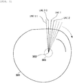
- FIG. 3 is a diagram for explaining reconstruction processing of a tomographic image of a vascular lumen surface 301 where the imaging core 250 is positioned. While the imaging core 250 makes one rotation (360 degrees), transmission and reception of the measurement light are performed a plurality of times. By transmitting and receiving light one time, single line data in a direction irradiated with the light can be obtained. Therefore, during one rotation, for example, by transmitting and receiving light 512 times, 512 pieces of line data extending radially from a rotation center 302 can be obtained.
- the 512 pieces of line data are dense in the vicinity of the rotation center position and become sparsely apart from each other as they are away from the rotation center position. Therefore, with respect to pixels in a vacant space of each line, known interpolation processing is performed to generate, and a two-dimensional tomographic image which can be visually perceived by a human is generated.
- a three-dimensional blood vessel image 402 can be obtained. Note that a center position of the two-dimensional tomographic image coincides with a rotation center position of the imaging core 250, but not a center position of the blood vessel cross-section. Although it is feeble, since the light is reflected by a lens surface of the imaging core 250, a surface of the catheter, or the like, several concentric circles occur with respect to the rotation center axis as indicated by reference numeral 303.
- the signal line cables 282 and 283 are electrically connected via a slip ring 231 provided in the pull-back unit 102. Note that in the drawing, the signal line cables 281 to 283 are indicated as being connected by one line, but actually, a plurality of signal lines are accommodated.
- the ultrasound transmitting and receiving control unit 232 operates under the control of the signal processing unit 201, drives the ultrasound transceiver accommodated in the imaging core 250, and generates an ultrasound pulse wave.
- the ultrasound transceiver converts the reflected wave from the vascular tissue into an electric signal, and supplies the electric signal to the ultrasound transmitting and receiving control unit 232.
- the ultrasound transmitting and receiving control unit 232 outputs the received ultrasound signal to the amplifier 233 and amplifies the ultrasound signal. Thereafter, the amplified ultrasound signal is supplied to the signal processing unit 201 as ultrasound data via a detector 234 and the A/D converter 235, and is temporarily stored in the memory 202.
- the A/D converter 235 performs a sampling the ultrasound signal output by the detector 234 at 30.6 MHz for 200 points, and generates single line digital data (ultrasound data) . Note that although 30.6 MHz is used here, it is calculated on the premise that 200 points are sampled for a depth of 5 mm when a sound speed is 1530 m/sec. Therefore, the sampling frequency is not particularly limited to this.
- the signal processing unit 201 generates an ultrasound image at each position in the blood vessel by converting the ultrasound data stored in the memory 202 to grayscale.
- the user executes the priming operation before the start of the processing in Fig. 5 .
- foreign matter such as air bubbles remains. In such cases, it is not in a state where the ultrasound transceiver can properly execute transmission and reception of signals, and accordingly, it is necessary to prompt the priming operation again.
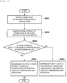
- step S501 the control device 103 determines whether or not the catheter accommodating the imaging core 250 is connected to the control device 103. If the connection is detected, the processing proceeds to S502. On the other hand, if the connection is not detected, the processing waits until the connection is detected. In step S502, the control device 103 receives a signal from the imaging core 250.
- the signal received here is at least one of a signal from the optical transceiver and a signal from the ultrasound transceiver.
- step S503 the control device 103 determines whether or not it is in a state where the ultrasound transceiver in the imaging core 250 can properly execute the transmission and reception of signals.
- the state where the ultrasound transceiver can properly execute the transmission and reception of signals may be, for example, a state where no foreign matter such as air bubbles remains in the catheter accommodating the imaging core 250.
- step S504 the control device 103 moves the imaging core 250 toward the distal side of the catheter before executing the optical path length adjustment processing described later.
- step S505 the control device 103 performs control so as to execute the optical path length adjustment for imaging using the optical transceiver of the imaging core 250. More specifically, the control (optical path length control) of a position of the one-axis stage 224 is performed via the optical path length adjustment drive unit 209. After executing the optical path length adjustment processing, the catheter is inserted into the blood vessel, and processing such as an image acquisition in the blood vessel is performed.
- step S506 the control device 103 announces a message prompting the execution of the priming operation (re-operation) to remove air bubbles in the catheter accommodating the imaging core 250.
- the control device 103 announces a message by any method such as voice output, a text display on the display apparatus 113, an output of a warning sound, and lighting of an LED.
- the processing returns to S502. This completes a series of processing in Fig. 5 . Note that the series of processing in Fig. 5 may be started when the control device 103 detects the execution of the previous priming operation.
- step S601 the control device 103 receives a signal from the ultrasound transceiver of the imaging core 250.
- step S602 the control device 103 acquires a signal intensity of an outside region of an outer surface of the catheter sheath.
- step S603 the control device 103 determines whether or not the signal intensity acquired in step S602 is equal to or greater than a previously stored threshold value (for example, a predetermined normal value).
- a previously stored threshold value for example, a predetermined normal value.
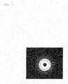
- Fig. 7 shows an example of an ultrasound tomographic image that can be obtained when the priming is correctly performed and air bubbles are not mixed. If the air bubbles are not mixed, as shown in Fig. 7 , multiple reflected signals of the catheter sheath are detected, and if the air bubbles are mixed, an ultrasound is not transmitted, so that a reflected signal is not obtained and a black image is obtained. If it is determined that the signal intensity is equal to or greater than the previously stored threshold value, the processing proceeds to S604.
- the processing proceeds to S605.
- it may be configured to be determined whether or not a signal received from the ultrasound transceiver includes the reflected signals from the inner surface and the outer surface of the catheter sheath or the multiple reflected signals, and if the reflected signals or the multiple reflected signals are included, it may be determined that it is in a state where the ultrasound transceiver can properly execute the transmission and reception.
- step S604 the control device 103 determines that it is in a state where the ultrasound transceiver can properly execute the transmission and reception of signals, and terminates the processing.
- step S605 the control device 103 determines that it is in a state where the ultrasound transceiver can properly execute the transmission and reception of signals, and terminates the processing. This completes a series of processing in Fig. 6 .
- step S801 the control device 103 receives a signal from the optical transceiver of the imaging core 250.
- step S802 the control device 103 acquires a signal intensity of a region from a lens surface constituting a part of the optical transceiver to an inner surface of the catheter sheath.
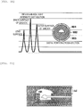
- Figs. 9A to 9C show examples of acquired intensity distribution of interference light.
- reference numeral 901 denotes the lens surface
- 902 denotes the inner surface of the catheter sheath
- 903 denotes the outer surface of the catheter sheath.
- FIG. 9A it can be seen that the intensities of the interference light are increased near the lens surface 901, the catheter sheath inner surface 902, and the catheter sheath outer surface 903.
- a normal value without mixed air bubbles is distributed as shown in Fig. 9A .
- step S803 the control device 103 determines whether or not the signal intensity acquired in step S802 is equal to or less than the previously stored threshold value.
- Fig. 9B shows a vertical cross-sectional diagram of a distal portion of the imaging core 250 when air bubbles (air) are mixed.
- the air bubbles are mixed as described above, as indicated by a broken line in Fig. 9C , the value becomes larger in a range of ⁇ d than the normal value in Fig. 9A (that is, the region from the lens surface to the inner surface of the catheter sheath).
- the fact that the signal intensity acquired in S802 is equal to or less than the previously stored threshold value can be considered to indicate a state where the ultrasound transceiver can properly execute the transmission and reception of signals (a state where no air bubbles are present) .
- a solid line in Fig. 9C shows the same as the interference light intensity distribution in Fig. 9A .
- it may be configured to compare an integrated value of the signal intensity in the range of ⁇ d with an integrated value of the normal value in the same range, or to compare average values in the range of ⁇ d with each other. Also, it may be configured to compare signal intensities at specific coordinates within the range of ⁇ d with each other. At that time, in order to reduce the influence of error, it may be determined that the air bubbles are mixed when the difference between the two compared values is equal to or greater than the threshold value.
- the processing proceeds to S804. On the other hand, if it is determined that the signal intensity is greater than the previously stored threshold value, the processing proceeds to S805.
- step S804 the control device 103 determines that it is in a state where the ultrasound transceiver can properly execute the transmission and reception of signals, and terminates the processing.
- step S805 the control device 103 determines that it is in a state wherein the ultrasound transceiver can properly execute the transmission and reception of signals, and terminates the processing. This completes a series of processing in Fig. 8 .
- Figs. 6 to 9C there have been described examples, in which whether or not it is in a state where the ultrasound transceiver can properly execute the transmission and reception of signals is determined based on the signal of the ultrasound transceiver or determined based on the signal of the optical transceiver.
- the present invention is not limited to these examples, and it may be determined by using the signals of both of these transceivers.
- the processes in Figs. 6 and 8 may each be executed, and when it is determined in both processes that it is in a state where the ultrasound transceiver can properly execute the transmission and reception of signals, it may be determined that it is not in a state where the ultrasound transceiver can properly execute the transmission and reception of signals in S503.
- the ultrasound transceiver may be determined whether or not it is in a state where the ultrasound transceiver can properly execute the transmission and reception, based on an intensity of the received signal or a signal interval from the inner surface of the catheter sheath or the inside region of the inner surface of the catheter sheath which are received from the optical transceiver.
- a control device receives signals from an imaging core including an optical transceiver and an ultrasound transceiver, determines whether or not it is in a state where the ultrasound transceiver can properly execute transmission and reception, based on at least one of the signal from the optical transceiver and the signal from the ultrasound transceiver which are received by the receiving unit, and controls execution of an optical path length adjustment for imaging with the optical transceiver when it is determined that the ultrasound transceiver can properly execute the transmission and reception.
- It may be configured to receive a mode selection in accordance with a user operation from among a first mode in which imaging using the optical transceiver is executed, a second mode in which imaging using the ultrasound transceiver is executed, and a third mode in which imaging using the optical transceiver and imaging using the ultrasound transceiver are executed. Further, when the second mode is selected, the optical path length adjustment may not be executed. This makes it possible to reduce the time required for unnecessary processing.
- turned-back of a signal may occur by performing Fourier transformation. Since a positional relationship of each signal on the lens surface, on the inner surface of the catheter sheath, and on the outer surface of the catheter sheath changes when a turned-back signal is generated, it is necessary to determine whether or not it is in a state where there is no turned-back signal. In a state where the optical path adjustment is not performed, the three signals obtained from the lens surface, the inner surface of the catheter sheath and the outer surface of the catheter sheath, have various positional relationships due to variations in the fiber length of the catheter.
- a horizontal axis represents an optical path difference
- numbers are assigned as a first signal, a second signal, and a third signal in order from a signal having a larger optical path difference.
- the state 1030 When each waveform of the state 1020 shifts to the left side, the state 1030 is obtained, and a waveform of the lens surface is turned back with using an origin as a boundary.
- the waveform of the lens surface which is turned back In order to distinguish the waveform of the lens surface which is turned back from the waveforms of the inner surface of the catheter sheath and outer surface of the catheter sheath (shown in a triangle) which are not turned back, the waveform of the lens surface which is turned back is shown in a parabolic form.
- the waveforms of the inner surface of the catheter sheath and the outer surface of the catheter sheath are also turned back with using the origin as a boundary.
- Determination processing should be performed in the absence of such turned-back to determine whether or not it is in a state where the ultrasound transceiver can properly execute the transmission and reception of signals.
- An interval between a signal on the inner surface of the catheter sheath and a signal on the outer surface of the catheter sheath is always constant.
- the signal on the lens surface occurs on the side where the optical path difference is large.
- the turned-back of a signal is not actually occurred in the state 1020.
- reflected signals obtained from the optical transceiver are set to be a first signal and a second signal in order from a signal having a larger optical path difference, it can be determined that it is in a state where turned-back does not occur (state 1010) when an interval between the first signal and the second signal is a predetermined value, and an optical path difference of the first signal and the optical path difference of the second signal are equal to or greater than a threshold value respectively. Therefore, in this case, it is configured so as to execute the determination processing.
- a horizontal axis represents an optical path difference and a vertical axis represents a signal intensity.
- a triangle with a letter L represents a waveform of the lens surface
- a triangle with a letter I represents a waveform of the inner surface of the catheter sheath
- a triangle with a letter O represents a waveform of the outer surface of the sheath.
- a state 1110 is a case where a region inside the catheter is water (physiological salt solution) and a region outside the catheter is also water. The region inside the catheter is filled with water, and it is in a proper priming state, that is, a state where the ultrasound transceiver can properly execute the transmission and reception of signals.
- a state 1120 is a case where a region inside the catheter is water and a region outside the catheter is air. The region inside the catheter is filled with water, and it is in a proper priming state, that is, a state where the ultrasound transceiver can properly execute the transmission and reception of signals. Note that a signal intensity of the outer surface of the sheath in which air exists becomes high.
- a state 1030 is a case where a region inside the catheter is air and a region outside the catheter is also air. Inside the catheter is filled with air, and it is not in a proper priming state, that is, it is not in a state where the ultrasound transceiver can properly execute the transmission and reception of signals. Note that a signal intensity of the outer surface of the sheath and a signal intensity of the inner surface of the sheath, in which air exists, become high. Also, an interval between the signal of the lens surface and the signal of the inner surface of the sheath becomes small.
- a state 1040 is a case where a region inside the catheter is air and a region outside the catheter is water. Inside the catheter is filled with air, and it is not in a proper priming state, that is, it is not in a state where the ultrasound transceiver can properly execute the transmission and reception of signals. Note that a signal intensity of the inner surface of the sheath in which air exists becomes high. Also, an interval between the signal of the lens surface and the signal of the inner surface of the sheath becomes small.
- a state 1050 is a case where a region inside the catheter is air and water (that is, a part of the inside the catheter is water), and a region outside the catheter is water. Air is included in the region inside the catheter, and it is not in a proper priming state, that is, it is not in a state where the ultrasound transceiver can properly execute the transmission and reception of signals. Note that another signal is detected between the signal of the lens surface and the signal of the inner surface of the catheter sheath.
- a signal received within a region from the lens surface to the inner surface of the catheter sheath is a reflected signal where an intensity of the signal is equal to or greater than a threshold value (state 1050), it is possible to determine that it is in a state where the ultrasound transceiver can properly execute the transmission and reception.
Landscapes
- Health & Medical Sciences (AREA)
- Life Sciences & Earth Sciences (AREA)
- Surgery (AREA)
- Engineering & Computer Science (AREA)
- Medical Informatics (AREA)
- Animal Behavior & Ethology (AREA)
- Radiology & Medical Imaging (AREA)
- Nuclear Medicine, Radiotherapy & Molecular Imaging (AREA)
- Biomedical Technology (AREA)
- Heart & Thoracic Surgery (AREA)
- Physics & Mathematics (AREA)
- Molecular Biology (AREA)
- Biophysics (AREA)
- Pathology (AREA)
- General Health & Medical Sciences (AREA)
- Public Health (AREA)
- Veterinary Medicine (AREA)
- Optics & Photonics (AREA)
- Vascular Medicine (AREA)
- Cardiology (AREA)
- Computer Vision & Pattern Recognition (AREA)
- Ultra Sonic Daignosis Equipment (AREA)
- Endoscopes (AREA)
Abstract
Description
- The present invention relates to a control device, an image diagnosis apparatus, a method for processing of a control device, and a program.
- When performing percutaneous treatment of a stenosed site causing a myocardial infarction or the like occurring in a body lumen such as a blood vessel and a vessel, in order to observe characteristics of the stenosed site or to observe condition after the treatment, a diagnostic catheter for acquiring an image of the body lumen by using an inspection wave such as ultrasound or light is used.
- In an intra vascular ultrasound (IVUS) diagnosis, it is common that an imaging core having an ultrasound transducer at a distal end of an insertion portion is provided in a rotatable manner and inserted into a body-cavity, and then scanning (radial scan) is performed while being rotated through a drive shaft or the like extending from a drive unit on a hand-side.
- In optical coherence tomographic (OCT) diagnosis utilizing wavelength sweeping, an optical probe unit having an imaging core inserted therein and equipped with an optical lens and an optical mirror (transceiver) attached at a distal end of an optical fiber is inserted into a blood vessel, measurement light is emitted into the blood vessel from the transceiver at the distal end while rotating the imaging core, and radial scanning in the blood vessel is performed by receiving reflected light from a biological tissue. Generally, a cross-sectional image of a blood vessel is drawn based on interference light generated by causing the received reflected light and reference light to interfere with each other.
- In OCT, an image with high resolution is obtained with respect to a vascular lumen surface, but only an image of the relatively shallow tissue from the vascular lumen surface can be obtained. On the other hand, in a case of the IVUS, although it is lower than the OCT in terms of the resolution of the obtained image, conversely, an image of a vascular tissue deeper than the OCT can be obtained. Therefore, recently, an image diagnosis apparatus having an imaging core equipped with a dual sensor combining a function of the IVUS and a function of the OCT (an image diagnosis apparatus including an ultrasound transceiver capable of transmitting and receiving ultrasound, and an optical transceiver capable of transmitting and receiving light) is proposed (see PTL 1).
- PTL 1:
JP-A-11-56752 - However, in a case of a dual sensor, it is necessary to check whether foreign matter such as air bubbles remains before acquiring an IVUS image, and it is also necessary to execute an optical path adjustment before acquiring an OCT image. At that time, although it is necessary to execute the optical path adjustment after a priming is surely performed, there is a possibility that a user may mistake a procedure and eventually leading to an erroneous diagnosis.
- The present invention has been made in view of the above problems, and it is an object thereof to provide a technology for reducing a burden of prior confirmation by a user and preventing an occurrence of an erroneous diagnosis.
- In order to achieve the above object, a control device according to an embodiment of the present invention includes the following elements: receiving means for receiving a signal from an imaging core including an optical transceiver and an ultrasound transceiver; determination means for determining whether or not it is in a state where the ultrasound transceiver is able to properly execute transmission and reception, based on at least one of a signal from the optical transceiver and a signal from the ultrasound transceiver which are received by the receiving means; and control means for performing control so that an optical path adjustment for imaging with the optical transceiver is executed when the determination means determines that the ultrasound transceiver is able to properly execute the transmission and reception.
- According to the present invention, it is possible to reduce a burden of prior confirmation by a user, and to prevent an occurrence of an erroneous diagnosis.
- Other features and advantages of the present invention will become apparent from the following description with reference to the accompanying drawings. Note that in the accompanying drawings, the same or similar configuration is denoted by the same reference numeral.
- The accompanying drawings are included in the specification, constitute a part of the specification, illustrate embodiments of the present invention, and are used to explain the principles of the present invention, together with the description.
-
Fig. 1 is a diagram showing an external appearance configuration of an image diagnosis apparatus according to an embodiment of the present invention. -
Fig. 2 is a diagram showing a configuration of an image diagnosis apparatus (control device and peripheral devices of the control device) according to the embodiment of the present invention. -
Fig. 3 is a diagram for explaining a cross-sectional image reconstruction processing according to the embodiment of the present invention. -
Fig. 4 is a diagram showing an example of three-dimensional model data of a reconstructed blood vessel according to the embodiment of the present invention. -
Fig. 5 is a flowchart showing a procedure of processing performed by the control device according to the embodiment of the present invention. -
Fig. 6 is a flowchart showing details of processing performed by the control device according to the embodiment of the present invention when a signal of an ultrasound receiver is used. -
Fig. 7 is a diagram showing an example of an ultrasound tomographic image obtained when no air bubbles are mixed, according to the embodiment of the present invention. -
Fig. 8 is a flowchart showing details of processing performed by the control device according to the embodiment of the present invention when a signal of an ultrasound receiver is used. -
Figs. 9A, 9B , and9C are diagrams for explaining an interference light intensity distribution in accordance with presence and absence of mixing of air bubbles according to the embodiment of the present invention. -
Fig. 10 is a diagram for explaining a turned-back of signals according to the embodiment of the present invention. -
Fig. 11 is a diagram for explaining a relationship between a signal interval and a signal intensity, and a state of the ultrasound receiver according to the embodiment of the present invention. - Hereinafter, each embodiment of the present invention will be described with reference to the drawings. Throughout the drawings, the same reference numerals refer to the same components.
- An image diagnosis apparatus according to the present embodiment will be described as having an IVUS function and an OCT function.
Fig. 1 is a diagram showing an external appearance configuration of animage diagnosis apparatus 100 according to an embodiment of the present invention. As shown inFig. 1 , theimage diagnosis apparatus 100 includes aprobe 101, a scanner and pull-back unit 102, acontrol device 103, and adisplay apparatus 113. The scanner and pull-back unit 102 and thecontrol device 103 are connected to each other via aconnector 105 by acable 104 accommodating a signal line and an optical fiber. Note that in the present embodiment, thecontrol device 103 and thedisplay apparatus 113 are described as separate bodies, but thecontrol device 103 may include thedisplay apparatus 113. - The
probe 101 is directly inserted into a blood vessel. A catheter accommodating an imaging core that includes an ultrasound transceiver for receiving a reflected wave from the inside of the blood vessel in addition to transmit an ultrasound based on a pulse signal and an optical transceiver for continuously receiving reflected light from the inside of the blood vessel in addition to continuously transmit the transmitted light (measurement light) into the blood vessel, is inserted in theprobe 101. Theimage diagnosis apparatus 100 measures a state inside the blood vessel by using the imaging core. - The
probe 101 is detachably attached to the scanner and pull-back unit 102, and by driving a built-in motor, the scanner and pull-back unit 102 defines an axial motion and a rotary direction motion in the blood vessel of the imaging core in the catheter inserted in theprobe 101. Further, the scanner and pull-back unit 102 acquires a reflected wave signal received by the ultrasound transceiver in the imaging core and reflected light received by the optical transceiver, and transmits the signal and the light to thecontrol device 103. - Upon measurement, the
control device 103 processes a function for inputting various setting values, or ultrasound data or optical interference data obtained by the measurement, and includes a function for displaying various blood vessel images. - In the
control device 103,reference numeral 111 denotes a main control unit. Themain control unit 111 generates line data from a reflected wave signal of the ultrasound obtained by the measurement, and generates an ultrasound tomographic image (IVUS image) through an interpolation processing. Furthermore, themain control unit 111 generates interference light data by causing the reflected light from the imaging core and the reference light obtained by separating light from a light source to interfere with each other, and also generates line data based on the interference light data and an optical tomographic image of the blood vessel based on an optical interference through the interpolation processing. - Reference numeral 111-1 denotes a printer and a DVD recorder, which print a processing result in the
main control unit 111 and store the processing result as data.Reference numeral 112 denotes an operation panel, and a user inputs various setting values and instructions via theoperation panel 112.Reference numeral 113 denotes an LCD monitor as a display apparatus, which displays various cross-sectional images generated by themain control unit 111.Reference numeral 114 denotes a mouse as a pointing device (coordinate input device). - Subsequently, a functional configuration of the image diagnosis apparatus 100 (mainly the control device 103) will be described.
Fig. 2 is a block configuration diagram of theimage diagnosis apparatus 100. Hereinafter, the functional configuration for implementing a wavelength sweeping type optical coherent tomographic diagnosis will be described with reference to the same figure. - In the figure,
reference numeral 201 denotes a signal processing unit which controls an entire image diagnosis apparatus, and is configured with a microprocessor and number of circuits.Reference numeral 210 denotes a nonvolatile storage device typified by a hard disk, and stores various programs or data files to be executed by thesignal processing unit 201.Reference numeral 202 denotes a memory (RAM) provided in thesignal processing unit 201.Reference numeral 203 denotes a wavelength swept light source, which is a light source that repeatedly generates light having a wavelength that changes within a preset range along a time axis.Reference numeral 2010 denotes an image acquisition unit which acquires an ultrasound tomographic image (IVUS image) or an optical tomographic image photographed by animaging core 250 described later.Reference numeral 2011 denotes a control unit which performs various processes and controls display on thedisplay apparatus 113.Reference numeral 2012 denotes a selection receiving unit which receives an input from a user via thedisplay apparatus 113, themouse 114 or the like when theoperation panel 112 and thedisplay apparatus 113 have a touch function, and performs various selection processing. - The light output from the wavelength swept
light source 203 is incident on one end of a firstsingle mode fiber 271 and is transmitted toward a distal side. The firstsingle mode fiber 271 is optically coupled to a fourthsingle mode fiber 275 in the middleoptical fiber coupler 272. - The light that is incident on the first
single mode fiber 271 and is emitted toward the distal side from theoptical fiber coupler 272 is guided to a secondsingle mode fiber 273 via aconnector 105. The other end of the secondsingle mode fiber 273 is connected to an optical rotary joint 230 in the pull-backunit 102. - On the other hand, the
probe 101 has anadapter 101a for connecting with the pull-backunit 102. Then, by connecting theprobe 101 to the pull-backunit 102 by using theadapter 101a, theprobe 101 is stably held in the pull-backunit 102. Furthermore, an end portion of the thirdsingle mode fiber 274 accommodated in theprobe 101 in a rotatable manner is connected to the optical rotary joint 230. As a result, the secondsingle mode fiber 273 and the thirdsingle mode fiber 274 are optically coupled. Animaging core 250 is provided on the other end of the third single mode fiber 274 (a head part side of the probe 101) . Theimaging core 250 is equipped with the optical transceiver including a mirror and a lens for emitting light in a direction substantially orthogonal to a rotation axis. - As a result, the light emitted from the wavelength swept
light source 203 is guided to theimaging core 250 provided at the end portion of the thirdsingle mode fiber 274 via the firstsingle mode fiber 271, the secondsingle mode fiber 273, and the thirdsingle mode fiber 274. The optical transceiver of theimaging core 250 emits the light in a direction orthogonal to the axis of the fiber and receives the reflected light. The received reflected light is guided in reverse this time, and returned to thecontrol device 103. - On the other hand, an optical path
length adjustment mechanism 220 for finely adjusting an optical path length of the reference light is provided at an opposite end portion of the fourthsingle mode fiber 275 coupled to theoptical fiber coupler 272. The optical pathlength adjustment mechanism 220 functions as an optical path length change means that changes the optical path length corresponding to a fluctuation in length so as to be able to absorb the fluctuation in length of eachprobe 101, such as when theprobe 101 is exchanged. Therefore, acollimating lens 225 positioned at the end portion of the fourthsingle mode fiber 275 is provided on a movable one-axis stage 224 as indicated by anarrow 226 which is an optical axis direction of the collimating lens. - Specifically, the one-
axis stage 224 functions as an optical path length change means having a variable range of the optical path length that can absorb a fluctuation of the optical path length of theprobe 101 when theprobe 101 is exchanged. Furthermore, the one-axis stage 224 also includes a function as an adjusting means for adjusting an offset. For example, even when the distal end of theprobe 101 is not in contact with the surface of the biological tissue, interference with the reflected light from the surface position of the biological tissue can be created by slightly changing the optical path length with the one-axis stage. - The optical path length is finely adjusted by the one-
axis stage 224 and light reflected by amirror 223 via agrating 221 and alens 222 is guided to the fourthsingle mode fiber 275 again. The light is mixed with light obtained from the secondsingle mode fiber 273 side at theoptical fiber coupler 272 and received by aphotodiode 204 as interference light. - The interference light received by the
photodiode 204 in this manner is photoelectrically converted, amplified by anamplifier 205, and then input to ademodulator 206. Thedemodulator 206 performs demodulation processing for extracting only a signal component of the interfered light, and an output thereof is input to an A/D converter 207 as an interference light signal. - The A/
D converter 207 generates single line digital data (interference light data) by sampling the interference light signal, for example, at 90 MHz for 2048 points. The reason why the sampling frequency is set to 90 MHz is based on the premise that about 90% of the wavelength sweeping cycle (25 µsec) is extracted as digital data of 2048 points when the wavelength sweeping repetition frequency is set to 40 kHz. However, there is no particular limitation to this. - The line by line interference light data generated by the A/
D converter 207 is input to thesignal processing unit 201 and temporarily stored in thememory 202. Then, thesignal processing unit 201 performs a frequency decomposition of the interference light data by using fast Fourier transform (FFT) to generate data (line data) in a depth direction, constructs an optical tomographic image at each position in the blood vessel by coordinate-conversion of the data, and outputs the image to thedisplay apparatus 113 at a predetermined frame rate. - The
signal processing unit 201 is further connected to an optical path lengthadjustment drive unit 209 and acommunication unit 208. Thesignal processing unit 201 performs control (optical path length control) of a position of the one-axis stage 224 via the optical path lengthadjustment drive unit 209. - The
communication unit 208 includes several drive circuits and communicates with the pull-backunit 102 under the control of thesignal processing unit 201. More specifically, thecommunication unit 208 is used for supplying a drive signal to a radial scanning motor for rotating the thirdsingle mode fiber 274 by the optical rotary joint in the pull-backunit 102, receiving a signal from anencoder unit 242 for detecting a rotational position of the radial motor, and supplying a drive signal to alinear drive unit 243. - Note that the above processing in the
signal processing unit 201 is also realized by executing a predetermined program by a computer. - With the above configuration, the
probe 101 is positioned at a blood vessel position (coronary artery or the like) of a patient to be diagnosed, and transparent flush liquid is discharged into the blood vessel through a guiding catheter or the like toward the distal end of theprobe 101 by a user operation. It is to exclude the influence of blood. Then, when the user inputs an instruction to start scanning, thesignal processing unit 201 drives the wavelength sweptlight source 203 to drive theradial scanning motor 241 and the linear drive unit 243 (hereinafter, light irradiation and light receiving processing by driving of theradial scanning motor 241 and thelinear drive unit 243 are also referred to as scanning). As a result, wavelength swept light is supplied from the wavelength sweptlight source 203 to theimaging core 250 through the above-described path. At this time, since theimaging core 250 at the distal position of theprobe 101 moves along the rotation axis while rotating, theimaging core 250 performs emission of light to the vascular lumen surface and reception of the reflected light thereof while rotating and while moving along a blood vessel axis. - Here, processing for generating one optical tomographic image will be briefly described with reference to
Fig. 3 . The figure is a diagram for explaining reconstruction processing of a tomographic image of avascular lumen surface 301 where theimaging core 250 is positioned. While theimaging core 250 makes one rotation (360 degrees), transmission and reception of the measurement light are performed a plurality of times. By transmitting and receiving light one time, single line data in a direction irradiated with the light can be obtained. Therefore, during one rotation, for example, by transmitting and receiving light 512 times, 512 pieces of line data extending radially from arotation center 302 can be obtained. The 512 pieces of line data are dense in the vicinity of the rotation center position and become sparsely apart from each other as they are away from the rotation center position. Therefore, with respect to pixels in a vacant space of each line, known interpolation processing is performed to generate, and a two-dimensional tomographic image which can be visually perceived by a human is generated. - Then, as shown in
Fig. 4 , by connecting generated two-dimensionaltomographic images 401 along the blood vessel axis, a three-dimensionalblood vessel image 402 can be obtained. Note that a center position of the two-dimensional tomographic image coincides with a rotation center position of theimaging core 250, but not a center position of the blood vessel cross-section. Although it is feeble, since the light is reflected by a lens surface of theimaging core 250, a surface of the catheter, or the like, several concentric circles occur with respect to the rotation center axis as indicated byreference numeral 303. - Next, a configuration and processing contents relating to an image formation using an ultrasound will be described. Scanning using an ultrasound is performed simultaneously with the above-described optical interference scanning. That is, the ultrasound transceiver accommodated in the
imaging core 250 performs an emission of ultrasound and a detection of the reflected wave while performing the scanning, rotating theimaging core 250, and moving in the catheter sheath of theprobe 101. Therefore, it is necessary to generate a drive signal for driving the ultrasound transceiver accommodated in theimaging core 250, and receive a detection signal of an ultrasound output by the ultrasound transceiver. An ultrasound transmitting and receivingcontrol unit 232 performs transmission of the drive signal and reception of the detected signal. The ultrasound transmitting and receivingcontrol unit 232 and theimaging core 250 are connected viasignal line cables imaging core 250 rotates, thesignal line cables slip ring 231 provided in the pull-backunit 102. Note that in the drawing, thesignal line cables 281 to 283 are indicated as being connected by one line, but actually, a plurality of signal lines are accommodated. - The ultrasound transmitting and receiving
control unit 232 operates under the control of thesignal processing unit 201, drives the ultrasound transceiver accommodated in theimaging core 250, and generates an ultrasound pulse wave. The ultrasound transceiver converts the reflected wave from the vascular tissue into an electric signal, and supplies the electric signal to the ultrasound transmitting and receivingcontrol unit 232. The ultrasound transmitting and receivingcontrol unit 232 outputs the received ultrasound signal to theamplifier 233 and amplifies the ultrasound signal. Thereafter, the amplified ultrasound signal is supplied to thesignal processing unit 201 as ultrasound data via adetector 234 and the A/D converter 235, and is temporarily stored in thememory 202. The A/D converter 235 performs a sampling the ultrasound signal output by thedetector 234 at 30.6 MHz for 200 points, and generates single line digital data (ultrasound data) . Note that although 30.6 MHz is used here, it is calculated on the premise that 200 points are sampled for a depth of 5 mm when a sound speed is 1530 m/sec. Therefore, the sampling frequency is not particularly limited to this. - The
signal processing unit 201 generates an ultrasound image at each position in the blood vessel by converting the ultrasound data stored in thememory 202 to grayscale. - Next, with reference to the flowchart of
Fig. 5 , a procedure of processing performed by thecontrol device 103 according to the embodiment of the present invention will be described. The user executes the priming operation before the start of the processing inFig. 5 . In some cases, however, foreign matter such as air bubbles remains. In such cases, it is not in a state where the ultrasound transceiver can properly execute transmission and reception of signals, and accordingly, it is necessary to prompt the priming operation again. - In step S501, the
control device 103 determines whether or not the catheter accommodating theimaging core 250 is connected to thecontrol device 103. If the connection is detected, the processing proceeds to S502. On the other hand, if the connection is not detected, the processing waits until the connection is detected. In step S502, thecontrol device 103 receives a signal from theimaging core 250. The signal received here is at least one of a signal from the optical transceiver and a signal from the ultrasound transceiver. - In step S503, the
control device 103 determines whether or not it is in a state where the ultrasound transceiver in theimaging core 250 can properly execute the transmission and reception of signals. The state where the ultrasound transceiver can properly execute the transmission and reception of signals may be, for example, a state where no foreign matter such as air bubbles remains in the catheter accommodating theimaging core 250. In the processing in S502 and S503, it is possible to make a determination based on a signal of the ultrasound transceiver, or to make a determination based on a signal of the optical transceiver, or to make a determination using signals of both of the transceivers. More details of the processing in S502 and S503 will be described later. If it is in a state where the transmission and reception can be properly executed, the processing proceeds to S504. On the other hand, if it is not in a state where the transmission and reception can be properly executed, the processing proceeds to S506. - In step S504, the
control device 103 moves theimaging core 250 toward the distal side of the catheter before executing the optical path length adjustment processing described later. In step S505, thecontrol device 103 performs control so as to execute the optical path length adjustment for imaging using the optical transceiver of theimaging core 250. More specifically, the control (optical path length control) of a position of the one-axis stage 224 is performed via the optical path lengthadjustment drive unit 209. After executing the optical path length adjustment processing, the catheter is inserted into the blood vessel, and processing such as an image acquisition in the blood vessel is performed. - In step S506, the
control device 103 announces a message prompting the execution of the priming operation (re-operation) to remove air bubbles in the catheter accommodating theimaging core 250. Thecontrol device 103 announces a message by any method such as voice output, a text display on thedisplay apparatus 113, an output of a warning sound, and lighting of an LED. Thereafter, the processing returns to S502. This completes a series of processing inFig. 5 . Note that the series of processing inFig. 5 may be started when thecontrol device 103 detects the execution of the previous priming operation. - Next, with reference to the flowchart in
Fig. 6 andFig. 7 , the details of the processing in S502 and S503 will be described. In this example, it is determined whether or not it is in a state where the ultrasound transceiver can properly execute the transmission and reception, based on a received signal from the ultrasound transceiver of theimaging core 250. The signal from the optical transceiver is not used. - In step S601, the
control device 103 receives a signal from the ultrasound transceiver of theimaging core 250. In step S602, thecontrol device 103 acquires a signal intensity of an outside region of an outer surface of the catheter sheath. - In step S603, the
control device 103 determines whether or not the signal intensity acquired in step S602 is equal to or greater than a previously stored threshold value (for example, a predetermined normal value).Fig. 7 shows an example of an ultrasound tomographic image that can be obtained when the priming is correctly performed and air bubbles are not mixed. If the air bubbles are not mixed, as shown inFig. 7 , multiple reflected signals of the catheter sheath are detected, and if the air bubbles are mixed, an ultrasound is not transmitted, so that a reflected signal is not obtained and a black image is obtained. If it is determined that the signal intensity is equal to or greater than the previously stored threshold value, the processing proceeds to S604. On the other hand, if it is determined that the signal intensity is less than the previously stored threshold value, the processing proceeds to S605. Alternatively, it may be configured to be determined whether or not a signal received from the ultrasound transceiver includes the reflected signals from the inner surface and the outer surface of the catheter sheath or the multiple reflected signals, and if the reflected signals or the multiple reflected signals are included, it may be determined that it is in a state where the ultrasound transceiver can properly execute the transmission and reception. - In step S604, the
control device 103 determines that it is in a state where the ultrasound transceiver can properly execute the transmission and reception of signals, and terminates the processing. In step S605, thecontrol device 103 determines that it is in a state where the ultrasound transceiver can properly execute the transmission and reception of signals, and terminates the processing. This completes a series of processing inFig. 6 . - Next, with reference to the flowchart in
Fig. 8 andFigs. 9A to 9C , the details of the processing in S502 and S503 will be described. In this example, it is determined whether or not it is in a state wherein the ultrasound transceiver can properly execute the transmission and reception, based on a received signal from the optical transceiver of theimaging core 250. The signal from the ultrasound transceiver is not used. - In step S801, the
control device 103 receives a signal from the optical transceiver of theimaging core 250. In step S802, thecontrol device 103 acquires a signal intensity of a region from a lens surface constituting a part of the optical transceiver to an inner surface of the catheter sheath.Figs. 9A to 9C show examples of acquired intensity distribution of interference light. InFig. 9A ,reference numeral 901 denotes the lens surface, 902 denotes the inner surface of the catheter sheath, and 903 denotes the outer surface of the catheter sheath. As shown inFig. 9A , it can be seen that the intensities of the interference light are increased near thelens surface 901, the catheter sheathinner surface 902, and the catheter sheathouter surface 903. A normal value without mixed air bubbles is distributed as shown inFig. 9A . - In step S803, the
control device 103 determines whether or not the signal intensity acquired in step S802 is equal to or less than the previously stored threshold value.Fig. 9B shows a vertical cross-sectional diagram of a distal portion of theimaging core 250 when air bubbles (air) are mixed. When the air bubbles are mixed as described above, as indicated by a broken line inFig. 9C , the value becomes larger in a range of Δd than the normal value inFig. 9A (that is, the region from the lens surface to the inner surface of the catheter sheath). The fact that the signal intensity acquired in S802 is equal to or less than the previously stored threshold value can be considered to indicate a state where the ultrasound transceiver can properly execute the transmission and reception of signals (a state where no air bubbles are present) . A solid line inFig. 9C shows the same as the interference light intensity distribution inFig. 9A . - In the processing in S803, it may be configured to compare an integrated value of the signal intensity in the range of Δd with an integrated value of the normal value in the same range, or to compare average values in the range of Δd with each other. Also, it may be configured to compare signal intensities at specific coordinates within the range of Δd with each other. At that time, in order to reduce the influence of error, it may be determined that the air bubbles are mixed when the difference between the two compared values is equal to or greater than the threshold value.
- If it is determined that the signal intensity is equal to or less than the previously stored threshold value, the processing proceeds to S804. On the other hand, if it is determined that the signal intensity is greater than the previously stored threshold value, the processing proceeds to S805.
- In step S804, the
control device 103 determines that it is in a state where the ultrasound transceiver can properly execute the transmission and reception of signals, and terminates the processing. In step S805, thecontrol device 103 determines that it is in a state wherein the ultrasound transceiver can properly execute the transmission and reception of signals, and terminates the processing. This completes a series of processing inFig. 8 . - As described above, referring to
Figs. 6 to 9C , there have been described examples, in which whether or not it is in a state where the ultrasound transceiver can properly execute the transmission and reception of signals is determined based on the signal of the ultrasound transceiver or determined based on the signal of the optical transceiver. The present invention is not limited to these examples, and it may be determined by using the signals of both of these transceivers. Specifically, the processes inFigs. 6 and8 may each be executed, and when it is determined in both processes that it is in a state where the ultrasound transceiver can properly execute the transmission and reception of signals, it may be determined that it is not in a state where the ultrasound transceiver can properly execute the transmission and reception of signals in S503. Also, it may be determined whether or not it is in a state where the ultrasound transceiver can properly execute the transmission and reception, based on an intensity of the received signal or a signal interval from the inner surface of the catheter sheath or the inside region of the inner surface of the catheter sheath which are received from the optical transceiver. - As described above, a control device according to the present embodiment receives signals from an imaging core including an optical transceiver and an ultrasound transceiver, determines whether or not it is in a state where the ultrasound transceiver can properly execute transmission and reception, based on at least one of the signal from the optical transceiver and the signal from the ultrasound transceiver which are received by the receiving unit, and controls execution of an optical path length adjustment for imaging with the optical transceiver when it is determined that the ultrasound transceiver can properly execute the transmission and reception.
- In this way, it is possible to automatically execute a series of operations such as a confirmation operation of whether or not air bubbles remain before acquiring the IVUS image, and an optical path adjustment operation necessary before acquiring the OCT image. It is necessary to perform the optical path length adjustment after the priming is surely performed and it is confirmed that no air bubble is mixed. However, according to the processing of the present invention, it is possible to prevent a user from performing an erroneous procedure and thus to prevent an occurrence of an erroneous diagnosis. In this way, it is possible to reduce a burden of prior confirmation by a user, and to prevent an occurrence of an erroneous diagnosis.
- Although a dual sensor having the IVUS function and the OCT function has been described in the present embodiment, it may not be always necessary to operate both functions at the time of diagnosis, and there may be a case where it is desired to operate only one function.
- It may be configured to receive a mode selection in accordance with a user operation from among a first mode in which imaging using the optical transceiver is executed, a second mode in which imaging using the ultrasound transceiver is executed, and a third mode in which imaging using the optical transceiver and imaging using the ultrasound transceiver are executed. Further, when the second mode is selected, the optical path length adjustment may not be executed. This makes it possible to reduce the time required for unnecessary processing.
- Subsequently, with reference to
Fig. 10 , description will be given of turned-back of signals according to the embodiment of the present invention. In OCT, turned-back of a signal may occur by performing Fourier transformation. Since a positional relationship of each signal on the lens surface, on the inner surface of the catheter sheath, and on the outer surface of the catheter sheath changes when a turned-back signal is generated, it is necessary to determine whether or not it is in a state where there is no turned-back signal. In a state where the optical path adjustment is not performed, the three signals obtained from the lens surface, the inner surface of the catheter sheath and the outer surface of the catheter sheath, have various positional relationships due to variations in the fiber length of the catheter. - In
Fig. 10 , a horizontal axis represents an optical path difference, and for each reflected signal from the lens surface, the inner surface of the catheter sheath, and the outer surface of the catheter sheath, numbers are assigned as a first signal, a second signal, and a third signal in order from a signal having a larger optical path difference. When each waveform of astate 1010 shifts to a left side, astate 1020 is obtained, and in thestate 1010 and thestate 1020, no turned-back of a signal has occurred. - When each waveform of the
state 1020 shifts to the left side, thestate 1030 is obtained, and a waveform of the lens surface is turned back with using an origin as a boundary. In order to distinguish the waveform of the lens surface which is turned back from the waveforms of the inner surface of the catheter sheath and outer surface of the catheter sheath (shown in a triangle) which are not turned back, the waveform of the lens surface which is turned back is shown in a parabolic form. As astate 1040 transitions to astate 1090, the waveforms of the inner surface of the catheter sheath and the outer surface of the catheter sheath are also turned back with using the origin as a boundary. - Determination processing should be performed in the absence of such turned-back to determine whether or not it is in a state where the ultrasound transceiver can properly execute the transmission and reception of signals. An interval between a signal on the inner surface of the catheter sheath and a signal on the outer surface of the catheter sheath is always constant. In addition, when the three signals obtained from the lens surface, the inner surface of the catheter sheath and the outer surface of the catheter sheath are turned back, the signal on the lens surface occurs on the side where the optical path difference is large.
- When the signal on the inner surface of the catheter sheath and the signal on the outer surface of the catheter sheath are each positioned at a position larger than a certain optical path difference (threshold value), it is determined that it is in a state where there is no turned-back signal. In an example of
Fig. 11 , it is determined that thestate 1010 is such that there is no turned-back signal andother states 1020 to 1090 are such that there are turned-back signals. - The turned-back of a signal is not actually occurred in the
state 1020. However, in order to clearly distinguish between thestate 1020 and thestate 1030, it is conditional that the signal on the inner surface of the catheter sheath and the signal on the outer surface of the catheter sheath are each positioned at a position greater than a certain optical path difference (threshold value). As a result, it is determined that only thestate 1010 is such that there is no turned-back signal. - As described above, before executing the determination processing as to whether or not it is in a state where the ultrasound transceiver can properly execute the transmission and reception of signals, if reflected signals obtained from the optical transceiver are set to be a first signal and a second signal in order from a signal having a larger optical path difference, it can be determined that it is in a state where turned-back does not occur (state 1010) when an interval between the first signal and the second signal is a predetermined value, and an optical path difference of the first signal and the optical path difference of the second signal are equal to or greater than a threshold value respectively. Therefore, in this case, it is configured so as to execute the determination processing.
- Next, with reference to
Fig. 11 , a relationship between a signal interval and a signal intensity, and a state of the ultrasound receiver according to the embodiment of the present invention will be described. InFig. 11 , a horizontal axis represents an optical path difference and a vertical axis represents a signal intensity. In addition, a triangle with a letter L represents a waveform of the lens surface, a triangle with a letter I represents a waveform of the inner surface of the catheter sheath, and a triangle with a letter O represents a waveform of the outer surface of the sheath. - A
state 1110 is a case where a region inside the catheter is water (physiological salt solution) and a region outside the catheter is also water. The region inside the catheter is filled with water, and it is in a proper priming state, that is, a state where the ultrasound transceiver can properly execute the transmission and reception of signals. Astate 1120 is a case where a region inside the catheter is water and a region outside the catheter is air. The region inside the catheter is filled with water, and it is in a proper priming state, that is, a state where the ultrasound transceiver can properly execute the transmission and reception of signals. Note that a signal intensity of the outer surface of the sheath in which air exists becomes high. - A
state 1030 is a case where a region inside the catheter is air and a region outside the catheter is also air. Inside the catheter is filled with air, and it is not in a proper priming state, that is, it is not in a state where the ultrasound transceiver can properly execute the transmission and reception of signals. Note that a signal intensity of the outer surface of the sheath and a signal intensity of the inner surface of the sheath, in which air exists, become high. Also, an interval between the signal of the lens surface and the signal of the inner surface of the sheath becomes small. - A
state 1040 is a case where a region inside the catheter is air and a region outside the catheter is water. Inside the catheter is filled with air, and it is not in a proper priming state, that is, it is not in a state where the ultrasound transceiver can properly execute the transmission and reception of signals. Note that a signal intensity of the inner surface of the sheath in which air exists becomes high. Also, an interval between the signal of the lens surface and the signal of the inner surface of the sheath becomes small. - A
state 1050 is a case where a region inside the catheter is air and water (that is, a part of the inside the catheter is water), and a region outside the catheter is water. Air is included in the region inside the catheter, and it is not in a proper priming state, that is, it is not in a state where the ultrasound transceiver can properly execute the transmission and reception of signals. Note that another signal is detected between the signal of the lens surface and the signal of the inner surface of the catheter sheath. - Therefore, when an interval between the reflected signal from the lens surface received from the optical transceiver and the reflected signal from the inner surface of the catheter sheath is equal to or greater than the threshold value (
state 1110 and state 1120), it is possible to determine that it is in a state where the ultrasound transceiver can properly execute the transmission and reception. Further, when an intensity of a reflected signal from the inner surface of the catheter sheath received from the optical transceiver is equal to or less than the threshold value (state 1110 and state 1120), it is possible to determine that it is in a state where the ultrasound transceiver can properly execute the transmission and reception. On the other hand, when a signal received within a region from the lens surface to the inner surface of the catheter sheath is a reflected signal where an intensity of the signal is equal to or greater than a threshold value (state 1050), it is possible to determine that it is in a state where the ultrasound transceiver can properly execute the transmission and reception. - The present invention is not limited to the above embodiment, and various modifications and variations are possible without departing from the spirit and scope of the present invention. Accordingly, in order to publicize the scope of the present invention, the following claims are attached.
- This application claims priority based on Japanese Patent Application No.
2016-192065 filed on September 29, 2016
Claims (15)
- A control device comprising:receiving means for receiving a signal from an imaging core including an optical transceiver and an ultrasound transceiver;determination means for determining whether or not it is in a state where the ultrasound transceiver is able to properly execute transmission and reception, based on at least one of a signal from the optical transceiver and a signal from the ultrasound transceiver which are received by the receiving means; andcontrol means for performing control so that an optical path length adjustment for imaging with the optical transceiver is executed when the determination means determines that the ultrasound transceiver is able to properly execute transmission and reception.
- The control device according to claim 1, further comprising:detection means for detecting a connection of a catheter accommodating the imaging core,wherein the determination means executes determination processing in response to detecting the connection of the catheter by the detection means.
- The control device according to claim 1 or 2,
wherein when the signals received from the ultrasound transceiver include a reflected signal or multiple reflected signals from an inner surface and an outer surface of a catheter sheath, the determination means determines that it is in a state where the ultrasound transceiver is able to properly execute the transmission and reception. - The control device according to claim 1 or 2,
wherein based on an intensity or a signal interval of received signals from an inner surface of a catheter sheath or a region inside of the inner surface of the catheter sheath, which are received from the optical transceiver, the determination means determines whether or not it is in a state where the ultrasound transceiver is able to properly execute the transmission and reception. - The control device according to any one of claims 1 to 4,
wherein, before executing the determination processing by the determination means, if reflected signals obtained from the optical transceiver are set to be a first signal and a second signal in order from a signal having a larger optical path difference, the determination means executes the determination processing when an interval between the first signal and the second signal is a predetermined value, and an optical path difference of the first signal and an optical path difference of the second signal are equal to or greater than a threshold value, respectively. - The control device according to claim 4,
wherein when an interval, between a reflected signal from a lens surface and a reflected signal from the inner surface of the catheter sheath, which are received from the optical transceiver, is equal to or greater than a threshold value, the determination means determines that it is in a state where the ultrasound transceiver is able to properly execute the transmission and reception. - The control device according to claim 4,
wherein when an intensity of a reflected signal from the inner surface of the catheter sheath, which is received from the optical transceiver is equal to or less than a threshold value, the determination means determines that it is in a state where the ultrasound transceiver is able to properly execute the transmission and reception. - The control device according to claim 4,
wherein when a signal received within a region from a lens surface to the inner surface of the catheter sheath is a reflected signal where an intensity of the signal is equal to or greater than a threshold value, the determination means determines that it is not in a state where the ultrasound transceiver is able to properly execute the transmission and reception. - The control device according to any one of claims 1 to 8,
wherein the state where the ultrasound transceiver is able to properly execute the transmission and reception is a state where no air bubbles are present in a catheter accommodating the imaging core. - The control device according to any one of claims 1 to 9, further comprising:
announcement means for announcing a message prompting execution of a priming operation for removing the air bubbles in a catheter accommodating the imaging core when the determination means determines that the ultrasound transceiver is not able to properly execute the transmission and reception. - The control device according to any one of claims 1 to 10, further comprising:selection means for selecting a mode, based on a user operation, from among a first mode in which imaging using the optical transceiver is executed, a second mode in which imaging using the ultrasound transceiver is executed, and a third mode in which imaging using the optical transceiver and imaging using the ultrasound transceiver are executed,wherein when the second mode is selected by the selection means, the control means does not execute the optical path length adjustment.
- The control device according to any one of claims 1 to 11,
wherein when the determination means determines that the ultrasound transceiver is able to properly execute the transmission and reception, the control means moves the imaging core to a distal side of the catheter before executing the optical path length adjustment. - An image diagnosis apparatus, comprising:the control device according to any one of claims 1 to 12; anda catheter accommodating the imaging core including the optical transceiver and the ultrasound transceiver.
- A program for causing a computer to function as each means of the control device according to any one of claims 1 to 12.
- A method for processing of a control device, comprising:a step of receiving a signal from an imaging core including an optical transceiver and an ultrasound transceiver;a step of determining whether or not it is in a state where the ultrasound transceiver is able to properly execute transmission and reception, based on at least one of a signal from the optical transceiver and a signal from the ultrasound transceiver which are received in the step of receiving; anda step of performing control so that an optical path length adjustment for imaging with the optical transceiver is executed when it is determined in the step of determining that the ultrasound transceiver is able to properly execute the transmission and reception.
Applications Claiming Priority (2)
| Application Number | Priority Date | Filing Date | Title |
|---|---|---|---|
| JP2016192065 | 2016-09-29 | ||
| PCT/JP2017/033105 WO2018061780A1 (en) | 2016-09-29 | 2017-09-13 | Control device, diagnostic imaging device, method for processing of control device, and program |
Publications (3)
| Publication Number | Publication Date |
|---|---|
| EP3520705A1 true EP3520705A1 (en) | 2019-08-07 |
| EP3520705A4 EP3520705A4 (en) | 2020-06-03 |
| EP3520705B1 EP3520705B1 (en) | 2024-11-06 |
Family
ID=61760633
Family Applications (1)
| Application Number | Title | Priority Date | Filing Date |
|---|---|---|---|
| EP17855736.9A Active EP3520705B1 (en) | 2016-09-29 | 2017-09-13 | Control device and program |
Country Status (4)
| Country | Link |
|---|---|
| US (1) | US11331082B2 (en) |
| EP (1) | EP3520705B1 (en) |
| JP (1) | JP6791976B2 (en) |
| WO (1) | WO2018061780A1 (en) |
Families Citing this family (21)
| Publication number | Priority date | Publication date | Assignee | Title |
|---|---|---|---|---|
| DE102018208555A1 (en) | 2018-05-30 | 2019-12-05 | Kardion Gmbh | Apparatus for anchoring a cardiac assist system in a blood vessel, method of operation, and method of making a device and cardiac assist system |
| DE102018208538A1 (en) | 2018-05-30 | 2019-12-05 | Kardion Gmbh | Intravascular blood pump and process for the production of electrical conductors |
| DE102018208537A1 (en) | 2018-05-30 | 2019-12-05 | Kardion Gmbh | Device for connecting a cardiac assist system to an insertion device and method for producing a device for connecting a cardiac assist system to an insertion device |
| DE102018208564A1 (en) | 2018-05-30 | 2019-12-05 | Kardion Gmbh | Controllable introducer sheath |
| DE102018208892A1 (en) | 2018-06-06 | 2019-12-12 | Kardion Gmbh | A sensor head device for a minimally invasive cardiac assist system and method of manufacturing a sensor head device for a cardiac assist system |
| DE102018208931A1 (en) | 2018-06-06 | 2019-12-12 | Kardion Gmbh | Apparatus for determining cardiac output for a cardiac assist system, cardiac assistive system and method for determining cardiac output |
| DE102018208929A1 (en) | 2018-06-06 | 2019-12-12 | Kardion Gmbh | A method of determining a flow rate of fluid flowing through an implanted vascular support system |
| DE102018208862A1 (en) | 2018-06-06 | 2019-12-12 | Kardion Gmbh | Implantable vascular support system |
| DE102018208870A1 (en) | 2018-06-06 | 2019-12-12 | Kardion Gmbh | A method of determining a fluid volume flow through an implanted vascular support system |
| DE102018208879A1 (en) | 2018-06-06 | 2020-01-30 | Kardion Gmbh | Method for determining a total fluid volume flow in the area of an implanted, vascular support system |
| DE102018208913A1 (en) | 2018-06-06 | 2019-12-12 | Kardion Gmbh | A method of operating an implanted ventricular assist device |
| DE102018208945A1 (en) | 2018-06-06 | 2019-12-12 | Kardion Gmbh | An analysis device and method for analyzing a viscosity of a fluid |
| DE102018208936A1 (en) | 2018-06-06 | 2019-12-12 | Kardion Gmbh | Determining device and method for determining a viscosity of a fluid |
| DE102018208899A1 (en) | 2018-06-06 | 2019-12-12 | Kardion Gmbh | A method for determining the speed of sound in a fluid in the region of an implanted vascular support system |
| DE102018208933A1 (en) | 2018-06-06 | 2019-12-12 | Kardion Gmbh | A method of determining a flow rate of fluid flowing through an implanted vascular support system |
| DE102018210076A1 (en) | 2018-06-21 | 2019-12-24 | Kardion Gmbh | Method and device for detecting a state of wear of a cardiac support system, method and device for operating a cardiac support system and cardiac support system |
| DE102018211297A1 (en) | 2018-07-09 | 2020-01-09 | Kardion Gmbh | Cardiac support system and method for monitoring the integrity of a support structure of a cardiac support system |
| DE102018213350A1 (en) | 2018-08-08 | 2020-02-13 | Kardion Gmbh | Device and method for monitoring a patient's health |
| WO2020223433A1 (en) * | 2019-04-30 | 2020-11-05 | Gentuity, Llc | Imaging probe with fluid pressurization element |
| US12589237B2 (en) | 2020-11-20 | 2026-03-31 | Kardion Gmbh | Mechanical circulatory support system with guidewire aid |
| US12502524B2 (en) | 2021-12-03 | 2025-12-23 | Kardion Gmbh | Cardiac pump with optical fiber for laser doppler |
Family Cites Families (6)
| Publication number | Priority date | Publication date | Assignee | Title |
|---|---|---|---|---|
| JP3772002B2 (en) | 1997-08-28 | 2006-05-10 | オリンパス株式会社 | In-subject tomographic imaging system |
| WO2013145635A1 (en) * | 2012-03-26 | 2013-10-03 | テルモ株式会社 | Probe and diagnostic imaging device |
| WO2014077880A1 (en) * | 2012-11-16 | 2014-05-22 | Lightlab Imaging, Inc. | Automated fluid delivery catheter and system |
| JP6437440B2 (en) * | 2013-09-27 | 2018-12-12 | テルモ株式会社 | Diagnostic imaging apparatus, operating method thereof, program, and computer-readable storage medium |
| WO2015045352A1 (en) * | 2013-09-27 | 2015-04-02 | テルモ株式会社 | Diagnostic imaging device |
| JP6315816B2 (en) * | 2014-09-25 | 2018-04-25 | テルモ株式会社 | Image processing apparatus, method of operating image processing apparatus, program, and storage medium |
-
2017
- 2017-09-13 EP EP17855736.9A patent/EP3520705B1/en active Active
- 2017-09-13 WO PCT/JP2017/033105 patent/WO2018061780A1/en not_active Ceased
- 2017-09-13 JP JP2018542366A patent/JP6791976B2/en active Active
-
2019
- 2019-03-29 US US16/369,513 patent/US11331082B2/en active Active
Also Published As
| Publication number | Publication date |
|---|---|
| WO2018061780A1 (en) | 2018-04-05 |
| JP6791976B2 (en) | 2020-11-25 |
| JPWO2018061780A1 (en) | 2019-07-11 |
| US20190223840A1 (en) | 2019-07-25 |
| EP3520705A4 (en) | 2020-06-03 |
| EP3520705B1 (en) | 2024-11-06 |
| US11331082B2 (en) | 2022-05-17 |
Similar Documents
| Publication | Publication Date | Title |
|---|---|---|
| EP3520705B1 (en) | Control device and program | |
| US10271818B2 (en) | Image processing apparatus, method of controlling image processing apparatus, program, and storage medium | |
| US10478156B2 (en) | Imaging apparatus for diagnosis, method of controlling the same, program, and computer readable storage medium | |
| JP6059334B2 (en) | Diagnostic imaging apparatus, information processing apparatus, operating method thereof, program, and computer-readable storage medium | |
| JP5981557B2 (en) | Diagnostic imaging equipment | |
| JP2016174809A (en) | Diagnostic imaging apparatus, control method therefor, program, and computer-readable storage medium | |
| EP3199109B1 (en) | Image diagnostic probe | |
| JP6587624B2 (en) | Tomographic image forming apparatus and control method | |
| US11129592B2 (en) | Image diagnostic apparatus and method and program | |
| WO2014162365A1 (en) | Image diagnostic device, method for controlling same, program, and computer-readable storage medium | |
| WO2016152624A1 (en) | Image diagnostic apparatus, control method therefor, program, and computer readable storage medium | |
| JP6794226B2 (en) | Diagnostic imaging device, operating method and program of diagnostic imaging device | |
| JP6437920B2 (en) | Diagnostic imaging equipment | |
| US11701003B2 (en) | Imaging apparatus, method of controlling imaging apparatus, computer program, and computer readable storage medium | |
| US20230013321A1 (en) | Drive unit, diagnostic imaging apparatus, and operation method | |
| WO2014162366A1 (en) | Image diagnostic device, method for controlling same, program, and computer-readable storage medium | |
| JP6563666B2 (en) | Diagnostic imaging apparatus, control method therefor, program, and computer-readable storage medium | |
| JP2018153563A (en) | Tomographic apparatus and control method of the same |
Legal Events
| Date | Code | Title | Description |
|---|---|---|---|
| STAA | Information on the status of an ep patent application or granted ep patent |
Free format text: STATUS: THE INTERNATIONAL PUBLICATION HAS BEEN MADE |
|
| PUAI | Public reference made under article 153(3) epc to a published international application that has entered the european phase |
Free format text: ORIGINAL CODE: 0009012 |
|
| STAA | Information on the status of an ep patent application or granted ep patent |
Free format text: STATUS: REQUEST FOR EXAMINATION WAS MADE |
|
| 17P | Request for examination filed |
Effective date: 20190426 |
|
| AK | Designated contracting states |
Kind code of ref document: A1 Designated state(s): AL AT BE BG CH CY CZ DE DK EE ES FI FR GB GR HR HU IE IS IT LI LT LU LV MC MK MT NL NO PL PT RO RS SE SI SK SM TR |
|
| AX | Request for extension of the european patent |
Extension state: BA ME |
|
| DAV | Request for validation of the european patent (deleted) | ||
| DAX | Request for extension of the european patent (deleted) | ||
| A4 | Supplementary search report drawn up and despatched |
Effective date: 20200508 |
|
| RIC1 | Information provided on ipc code assigned before grant |
Ipc: A61B 8/08 20060101ALI20200501BHEP Ipc: A61B 8/12 20060101AFI20200501BHEP Ipc: A61B 8/00 20060101ALI20200501BHEP Ipc: A61B 1/00 20060101ALI20200501BHEP Ipc: A61B 5/00 20060101ALI20200501BHEP |
|
| STAA | Information on the status of an ep patent application or granted ep patent |
Free format text: STATUS: EXAMINATION IS IN PROGRESS |
|
| 17Q | First examination report despatched |
Effective date: 20221223 |
|
| GRAP | Despatch of communication of intention to grant a patent |
Free format text: ORIGINAL CODE: EPIDOSNIGR1 |
|
| STAA | Information on the status of an ep patent application or granted ep patent |
Free format text: STATUS: GRANT OF PATENT IS INTENDED |
|
| INTG | Intention to grant announced |
Effective date: 20240617 |
|
| GRAS | Grant fee paid |
Free format text: ORIGINAL CODE: EPIDOSNIGR3 |
|
| GRAA | (expected) grant |
Free format text: ORIGINAL CODE: 0009210 |
|
| STAA | Information on the status of an ep patent application or granted ep patent |
Free format text: STATUS: THE PATENT HAS BEEN GRANTED |
|
| AK | Designated contracting states |
Kind code of ref document: B1 Designated state(s): AL AT BE BG CH CY CZ DE DK EE ES FI FR GB GR HR HU IE IS IT LI LT LU LV MC MK MT NL NO PL PT RO RS SE SI SK SM TR |
|
| REG | Reference to a national code |
Ref country code: GB Ref legal event code: FG4D |
|
| REG | Reference to a national code |
Ref country code: CH Ref legal event code: EP |
|
| REG | Reference to a national code |
Ref country code: DE Ref legal event code: R096 Ref document number: 602017085997 Country of ref document: DE |
|
| REG | Reference to a national code |
Ref country code: IE Ref legal event code: FG4D |
|
| REG | Reference to a national code |
Ref country code: DE Ref legal event code: R084 Ref document number: 602017085997 Country of ref document: DE |
|
| REG | Reference to a national code |
Ref country code: LT Ref legal event code: MG9D |
|
| REG | Reference to a national code |
Ref country code: NL Ref legal event code: MP Effective date: 20241106 |
|
| PG25 | Lapsed in a contracting state [announced via postgrant information from national office to epo] |
Ref country code: PT Free format text: LAPSE BECAUSE OF FAILURE TO SUBMIT A TRANSLATION OF THE DESCRIPTION OR TO PAY THE FEE WITHIN THE PRESCRIBED TIME-LIMIT Effective date: 20250306 Ref country code: HR Free format text: LAPSE BECAUSE OF FAILURE TO SUBMIT A TRANSLATION OF THE DESCRIPTION OR TO PAY THE FEE WITHIN THE PRESCRIBED TIME-LIMIT Effective date: 20241106 Ref country code: IS Free format text: LAPSE BECAUSE OF FAILURE TO SUBMIT A TRANSLATION OF THE DESCRIPTION OR TO PAY THE FEE WITHIN THE PRESCRIBED TIME-LIMIT Effective date: 20250306 |
|
| PG25 | Lapsed in a contracting state [announced via postgrant information from national office to epo] |
Ref country code: NL Free format text: LAPSE BECAUSE OF FAILURE TO SUBMIT A TRANSLATION OF THE DESCRIPTION OR TO PAY THE FEE WITHIN THE PRESCRIBED TIME-LIMIT Effective date: 20241106 Ref country code: FI Free format text: LAPSE BECAUSE OF FAILURE TO SUBMIT A TRANSLATION OF THE DESCRIPTION OR TO PAY THE FEE WITHIN THE PRESCRIBED TIME-LIMIT Effective date: 20241106 |
|
| REG | Reference to a national code |
Ref country code: AT Ref legal event code: MK05 Ref document number: 1738485 Country of ref document: AT Kind code of ref document: T Effective date: 20241106 |
|
| PG25 | Lapsed in a contracting state [announced via postgrant information from national office to epo] |
Ref country code: BG Free format text: LAPSE BECAUSE OF FAILURE TO SUBMIT A TRANSLATION OF THE DESCRIPTION OR TO PAY THE FEE WITHIN THE PRESCRIBED TIME-LIMIT Effective date: 20241106 |
|
| PG25 | Lapsed in a contracting state [announced via postgrant information from national office to epo] |
Ref country code: ES Free format text: LAPSE BECAUSE OF FAILURE TO SUBMIT A TRANSLATION OF THE DESCRIPTION OR TO PAY THE FEE WITHIN THE PRESCRIBED TIME-LIMIT Effective date: 20241106 |
|
| PG25 | Lapsed in a contracting state [announced via postgrant information from national office to epo] |
Ref country code: NO Free format text: LAPSE BECAUSE OF FAILURE TO SUBMIT A TRANSLATION OF THE DESCRIPTION OR TO PAY THE FEE WITHIN THE PRESCRIBED TIME-LIMIT Effective date: 20250206 |
|
| PG25 | Lapsed in a contracting state [announced via postgrant information from national office to epo] |
Ref country code: AT Free format text: LAPSE BECAUSE OF FAILURE TO SUBMIT A TRANSLATION OF THE DESCRIPTION OR TO PAY THE FEE WITHIN THE PRESCRIBED TIME-LIMIT Effective date: 20241106 Ref country code: LV Free format text: LAPSE BECAUSE OF FAILURE TO SUBMIT A TRANSLATION OF THE DESCRIPTION OR TO PAY THE FEE WITHIN THE PRESCRIBED TIME-LIMIT Effective date: 20241106 Ref country code: GR Free format text: LAPSE BECAUSE OF FAILURE TO SUBMIT A TRANSLATION OF THE DESCRIPTION OR TO PAY THE FEE WITHIN THE PRESCRIBED TIME-LIMIT Effective date: 20250207 |
|
| PG25 | Lapsed in a contracting state [announced via postgrant information from national office to epo] |
Ref country code: PL Free format text: LAPSE BECAUSE OF FAILURE TO SUBMIT A TRANSLATION OF THE DESCRIPTION OR TO PAY THE FEE WITHIN THE PRESCRIBED TIME-LIMIT Effective date: 20241106 |
|
| PG25 | Lapsed in a contracting state [announced via postgrant information from national office to epo] |
Ref country code: RS Free format text: LAPSE BECAUSE OF FAILURE TO SUBMIT A TRANSLATION OF THE DESCRIPTION OR TO PAY THE FEE WITHIN THE PRESCRIBED TIME-LIMIT Effective date: 20250206 |
|
| PG25 | Lapsed in a contracting state [announced via postgrant information from national office to epo] |
Ref country code: SM Free format text: LAPSE BECAUSE OF FAILURE TO SUBMIT A TRANSLATION OF THE DESCRIPTION OR TO PAY THE FEE WITHIN THE PRESCRIBED TIME-LIMIT Effective date: 20241106 |
|
| PG25 | Lapsed in a contracting state [announced via postgrant information from national office to epo] |
Ref country code: DK Free format text: LAPSE BECAUSE OF FAILURE TO SUBMIT A TRANSLATION OF THE DESCRIPTION OR TO PAY THE FEE WITHIN THE PRESCRIBED TIME-LIMIT Effective date: 20241106 |
|
| PG25 | Lapsed in a contracting state [announced via postgrant information from national office to epo] |
Ref country code: EE Free format text: LAPSE BECAUSE OF FAILURE TO SUBMIT A TRANSLATION OF THE DESCRIPTION OR TO PAY THE FEE WITHIN THE PRESCRIBED TIME-LIMIT Effective date: 20241106 |
|
| PG25 | Lapsed in a contracting state [announced via postgrant information from national office to epo] |
Ref country code: RO Free format text: LAPSE BECAUSE OF FAILURE TO SUBMIT A TRANSLATION OF THE DESCRIPTION OR TO PAY THE FEE WITHIN THE PRESCRIBED TIME-LIMIT Effective date: 20241106 |
|
| PG25 | Lapsed in a contracting state [announced via postgrant information from national office to epo] |
Ref country code: SK Free format text: LAPSE BECAUSE OF FAILURE TO SUBMIT A TRANSLATION OF THE DESCRIPTION OR TO PAY THE FEE WITHIN THE PRESCRIBED TIME-LIMIT Effective date: 20241106 |
|
| PG25 | Lapsed in a contracting state [announced via postgrant information from national office to epo] |
Ref country code: CZ Free format text: LAPSE BECAUSE OF FAILURE TO SUBMIT A TRANSLATION OF THE DESCRIPTION OR TO PAY THE FEE WITHIN THE PRESCRIBED TIME-LIMIT Effective date: 20241106 |
|
| PG25 | Lapsed in a contracting state [announced via postgrant information from national office to epo] |
Ref country code: IT Free format text: LAPSE BECAUSE OF FAILURE TO SUBMIT A TRANSLATION OF THE DESCRIPTION OR TO PAY THE FEE WITHIN THE PRESCRIBED TIME-LIMIT Effective date: 20241106 |
|
| REG | Reference to a national code |
Ref country code: DE Ref legal event code: R097 Ref document number: 602017085997 Country of ref document: DE |
|
| PG25 | Lapsed in a contracting state [announced via postgrant information from national office to epo] |
Ref country code: SE Free format text: LAPSE BECAUSE OF FAILURE TO SUBMIT A TRANSLATION OF THE DESCRIPTION OR TO PAY THE FEE WITHIN THE PRESCRIBED TIME-LIMIT Effective date: 20241106 |
|
| PLBE | No opposition filed within time limit |
Free format text: ORIGINAL CODE: 0009261 |
|
| STAA | Information on the status of an ep patent application or granted ep patent |
Free format text: STATUS: NO OPPOSITION FILED WITHIN TIME LIMIT |
|
| PGFP | Annual fee paid to national office [announced via postgrant information from national office to epo] |
Ref country code: DE Payment date: 20250730 Year of fee payment: 9 |
|
| 26N | No opposition filed |
Effective date: 20250807 |
|
| PGFP | Annual fee paid to national office [announced via postgrant information from national office to epo] |
Ref country code: FR Payment date: 20250808 Year of fee payment: 9 |
|
| REG | Reference to a national code |
Ref country code: CH Ref legal event code: H13 Free format text: ST27 STATUS EVENT CODE: U-0-0-H10-H13 (AS PROVIDED BY THE NATIONAL OFFICE) Effective date: 20260504 |