EP3519728B1 - Lighting assembly with diffusor - Google Patents
Lighting assembly with diffusor Download PDFInfo
- Publication number
- EP3519728B1 EP3519728B1 EP17772647.8A EP17772647A EP3519728B1 EP 3519728 B1 EP3519728 B1 EP 3519728B1 EP 17772647 A EP17772647 A EP 17772647A EP 3519728 B1 EP3519728 B1 EP 3519728B1
- Authority
- EP
- European Patent Office
- Prior art keywords
- diffusion
- diffusor
- lighting assembly
- assembly according
- diffusion portions
- Prior art date
- Legal status (The legal status is an assumption and is not a legal conclusion. Google has not performed a legal analysis and makes no representation as to the accuracy of the status listed.)
- Active
Links
Images


Classifications
-
- F—MECHANICAL ENGINEERING; LIGHTING; HEATING; WEAPONS; BLASTING
- F21—LIGHTING
- F21V—FUNCTIONAL FEATURES OR DETAILS OF LIGHTING DEVICES OR SYSTEMS THEREOF; STRUCTURAL COMBINATIONS OF LIGHTING DEVICES WITH OTHER ARTICLES, NOT OTHERWISE PROVIDED FOR
- F21V3/00—Globes; Bowls; Cover glasses
- F21V3/04—Globes; Bowls; Cover glasses characterised by materials, surface treatments or coatings
- F21V3/06—Globes; Bowls; Cover glasses characterised by materials, surface treatments or coatings characterised by the material
- F21V3/062—Globes; Bowls; Cover glasses characterised by materials, surface treatments or coatings characterised by the material the material being plastics
- F21V3/0625—Globes; Bowls; Cover glasses characterised by materials, surface treatments or coatings characterised by the material the material being plastics the material diffusing light, e.g. translucent plastics
-
- F—MECHANICAL ENGINEERING; LIGHTING; HEATING; WEAPONS; BLASTING
- F21—LIGHTING
- F21K—NON-ELECTRIC LIGHT SOURCES USING LUMINESCENCE; LIGHT SOURCES USING ELECTROCHEMILUMINESCENCE; LIGHT SOURCES USING CHARGES OF COMBUSTIBLE MATERIAL; LIGHT SOURCES USING SEMICONDUCTOR DEVICES AS LIGHT-GENERATING ELEMENTS; LIGHT SOURCES NOT OTHERWISE PROVIDED FOR
- F21K9/00—Light sources using semiconductor devices as light-generating elements, e.g. using light-emitting diodes [LED] or lasers
- F21K9/60—Optical arrangements integrated in the light source, e.g. for improving the colour rendering index or the light extraction
- F21K9/64—Optical arrangements integrated in the light source, e.g. for improving the colour rendering index or the light extraction using wavelength conversion means distinct or spaced from the light-generating element, e.g. a remote phosphor layer
-
- F—MECHANICAL ENGINEERING; LIGHTING; HEATING; WEAPONS; BLASTING
- F21—LIGHTING
- F21K—NON-ELECTRIC LIGHT SOURCES USING LUMINESCENCE; LIGHT SOURCES USING ELECTROCHEMILUMINESCENCE; LIGHT SOURCES USING CHARGES OF COMBUSTIBLE MATERIAL; LIGHT SOURCES USING SEMICONDUCTOR DEVICES AS LIGHT-GENERATING ELEMENTS; LIGHT SOURCES NOT OTHERWISE PROVIDED FOR
- F21K9/00—Light sources using semiconductor devices as light-generating elements, e.g. using light-emitting diodes [LED] or lasers
- F21K9/60—Optical arrangements integrated in the light source, e.g. for improving the colour rendering index or the light extraction
- F21K9/65—Optical arrangements integrated in the light source, e.g. for improving the colour rendering index or the light extraction specially adapted for changing the characteristics or the distribution of the light, e.g. by adjustment of parts
-
- F—MECHANICAL ENGINEERING; LIGHTING; HEATING; WEAPONS; BLASTING
- F21—LIGHTING
- F21S—NON-PORTABLE LIGHTING DEVICES; SYSTEMS THEREOF; VEHICLE LIGHTING DEVICES SPECIALLY ADAPTED FOR VEHICLE EXTERIORS
- F21S4/00—Lighting devices or systems using a string or strip of light sources
- F21S4/20—Lighting devices or systems using a string or strip of light sources with light sources held by or within elongate supports
- F21S4/22—Lighting devices or systems using a string or strip of light sources with light sources held by or within elongate supports flexible or deformable, e.g. into a curved shape
-
- F—MECHANICAL ENGINEERING; LIGHTING; HEATING; WEAPONS; BLASTING
- F21—LIGHTING
- F21S—NON-PORTABLE LIGHTING DEVICES; SYSTEMS THEREOF; VEHICLE LIGHTING DEVICES SPECIALLY ADAPTED FOR VEHICLE EXTERIORS
- F21S4/00—Lighting devices or systems using a string or strip of light sources
- F21S4/20—Lighting devices or systems using a string or strip of light sources with light sources held by or within elongate supports
- F21S4/28—Lighting devices or systems using a string or strip of light sources with light sources held by or within elongate supports rigid, e.g. LED bars
-
- F—MECHANICAL ENGINEERING; LIGHTING; HEATING; WEAPONS; BLASTING
- F21—LIGHTING
- F21Y—INDEXING SCHEME ASSOCIATED WITH SUBCLASSES F21K, F21L, F21S and F21V, RELATING TO THE FORM OR THE KIND OF THE LIGHT SOURCES OR OF THE COLOUR OF THE LIGHT EMITTED
- F21Y2103/00—Elongate light sources, e.g. fluorescent tubes
- F21Y2103/10—Elongate light sources, e.g. fluorescent tubes comprising a linear array of point-like light-generating elements
-
- F—MECHANICAL ENGINEERING; LIGHTING; HEATING; WEAPONS; BLASTING
- F21—LIGHTING
- F21Y—INDEXING SCHEME ASSOCIATED WITH SUBCLASSES F21K, F21L, F21S and F21V, RELATING TO THE FORM OR THE KIND OF THE LIGHT SOURCES OR OF THE COLOUR OF THE LIGHT EMITTED
- F21Y2115/00—Light-generating elements of semiconductor light sources
- F21Y2115/10—Light-emitting diodes [LED]
Definitions
- the invention relates to the field of lighting, and more specifically to a lighting assembly.
- LEDs are used today for an increasing number of lighting applications due to advantageous properties such as high energy efficiency, compact size and long lifetime. However, while many lighting applications require light output to be spread over a larger area, the light output from LEDs is rather concentrated to small areas. If a plurality of LEDs is used, these are generally arranged at a certain distance from each other due to thermal limitations and for cost reasons.
- JP 2013 196847 A discloses an LED lamp with LEDs provided at a substrate in a glass tube.
- a diffusion reflection part is formed on the circumference of the glass tube.
- the width of the diffusion reflection part in circumference direction varies throughout the longitudinal direction of the glass tube.
- EP 1 028 348 A1 discloses an arrangement for producing a uniform illumination from a light source, for a surface to be illuminated, comprising a light source located behind a screen. The screen thickness varies over the surface cross section.
- WO 2008/025909 A1 discloses an optical system comprising a diffuser for a homogenized luminance output.
- LED lighting elements should be understood to cover any known type of solid state lighting element, such as e.g. light emitting diodes, organic light emitting diodes, laser diodes, etc.
- Each LED lighting element may comprise one or a plurality of such components arranged in proximity.
- one LED lighting element may comprise two or more dies of light emitting diodes.
- the LED lighting elements may be individually packaged components, i.e. they may comprise individual housings with electrical terminals. Also, it is possible to provide the LED lighting elements as pure unpackaged LED dies, e.g. connected directly to a leadframe.
- the lighting assembly comprises at least two LED lighting elements, but a larger number is preferred, such as at least 3, 4 or 5, further preferably e.g. more than 10.
- the LED lighting elements are arranged at a distance from each other. While this is not required, a plurality of LED elements may be equally spaced. In particular, a plurality of LED lighting elements may be arranged in a line, e.g. equidistant according to a constant pitch.
- the lighting assembly according to the invention further comprises a diffusor element made from silicone and extending over the LED lighting elements, i.e. being arranged such that light therefrom is emitted into the direction of the diffusor element.
- the diffusor element is translucent but not entirely transparent, i.e. light traversing the diffusor element is scattered.
- the diffusor element may comprise diffusion particles embedded in a transparent or translucent material, such as, for example, TiO 2 particles dispersed in transparent.
- the inventors have considered that the light input from two or more LED lighting elements arranged at a distance from each other is inhomogeneous.
- the optical properties of the diffusor element could be chosen non-homogeneous in order to counteract and compensate for the non-homogeneous light input.
- light output may thus be homogenized.
- the diffusor element may be comprised of different diffusion portions providing different levels of optical diffusion in different locations.
- at least two types of diffusion portions may be provided with different levels of diffusion.
- First diffusion portions may be arranged in front of the LED lighting elements, and at least one second diffusion portion may be arranged in between the first diffusion portions.
- the first diffusion portions are disposed to cause stronger optical diffusion than the second diffusion portion.
- Embodiments of a lighting assembly including such a non-homogeneous diffusor element with first and second diffusion portions have proven to provide a significantly homogenized light output as compared to a homogeneous diffusor element.
- a definition of the most preferred, fully homogeneous appearance would be a lambertian type emission of light from the surface with fully uniform luminance, i.e. no spatial variation.
- a homogeneity value may be defined as the standard deviation of the luminance values over the surface area divided by the mean luminance value over the surface area. Homogeneity values of e.g. 50%, preferably 40% or less may be regarded satisfactory for some applications. Values of 25% or less are preferered; especially preferred are values of 10% or less, which are generally perceived as fully homogeneous.
- the lighting assembly according to the invention is especially suited to provide line-shaped illumination, in particular in very compact assemblies.
- a plurality, or all, of the LED lighting elements may be arranged in a line.
- One or more diffusor elements may be provided to cover the LED lighting elements, being arranged such that first diffusion portions are each positioned in front of the LED lighting elements. Consequently, second diffusion portions may be arranged in between the LED lighting elements.
- the level of optical diffusion varies continuously between the first and second diffusion portions.
- the level of optical diffusion decreases monotonously from the first diffusion portions to the second diffusion portions.
- the diffusor element comprises diffusion particles embedded in a transparent or translucent material.
- the density of the diffusion particles may vary.
- the density in the first diffusion portions arranged in front of the LED lighting elements may be higher than the density in the second diffusion portions arranged in between the LED lighting elements.
- the different levels of optical diffusion in the first and second diffusion portions may be achieved by varying the thickness of the diffusor element.
- the thickness may e.g. be measured perpendicularly to a line or plane in which the LEDs are arranged.
- the first diffusion portions may be provided with a higher thickness than the second diffusion portions, such that light traversing the diffusor element at the first diffusion portions propagates a longer distance through the diffusor element in the first diffusion portions, thus undergoing stronger diffusion.
- a diffusor element of varying thickness may have a constant density of diffusion particles, which is easier to manufacture. However, it is also possible to combine a variation in particle density and a variation in thickness.
- the level of optical diffusion of an elongate diffusor element may vary along its length. If the LED elements are arranged at equal distances according to a first pitch, it is advantageous to provide a variation in the level of optical diffusion to be equally periodical with a second pitch equal to the first pitch.
- the thickness of the diffusor element may vary periodically with the same pitch as the arrangement of the LED lighting elements, and preferably the arrangement of the LED lighting elements and of the thickness are spatially in phase, such that the maxima of the thickness are arranged directly above the LED lighting elements.
- a top surface of the diffusor element may have a plane shape.
- An opposed bottom surface oriented towards the LED lighting elements may have an undulating shape to obtain varying thickness.
- the variation of the thickness of the diffusor element may e.g. be such that first diffusion portions, e.g. corresponding to the maximum thickness, are at least 50% thicker than second diffusion portions, e.g. corresponding to the minimum thickness of the diffusor element. Further preferred, the first diffusion portions are at least 100% thicker than the second diffusion portions.
- the LED lighting elements are arranged with electrical conductors extending between them.
- a leadframe may connect the LED lighting elements.
- a flexible housing at least partly surrounding the LED lighting elements and the diffusor.
- the housing may comprise reflective surfaces to improve efficiency.
- at least the inner surfaces of the housing oriented towards the LED lighting elements may be reflective.
- the housing may be made of a flexible material, e.g. silicone.
- the lighting assembly according to the invention is particularly suited to be manufactured with very compact dimensions.
- the height e.g. measured from the bottom surface of the lighting assembly to a light emitting top surface of the diffusor may be less than 1 cm, further preferably equal to or less than 8 mm, particularly preferably 5 mm or less.
- the height may be less than the pitch, preferably correspond to 50% or less of the pitch of the LED elements.
- An elongate lighting assembly 10 is shown in fig. 1 , comprising a bottom surface 12 and a top surface 14 from which light is emitted. Electrical connections 16 shown schematically deliver electrical operating power to the lighting assembly 10.
- the lighting assembly 10 is of particularly small dimensions, in a preferred example with a height measured from the bottom surface 12 to the top surface 14 of only 4 mm and a width of only 7 mm.
- the length in a longitudinal direction L may vary, but will be significantly greater than the width, e.g. at least 10 times greater.
- each LED 20 comprises a LED die 22 surrounded by a housing 24.
- the LEDs 20 are electrically interconnected by electrical conductors forming a leadframe 26.
- the LEDs 20 are disposed to emit light into the direction of the top surface 14, as schematically shown in dotted lines in fig. 3 .
- the light from the LEDs 20 is emitted at the top surface 14 through a diffusor 30.
- the diffusor 30 is made of transparent silicone with dispersed TiO 2 particles, such that the light emitted from the LEDs 20 is scattered and emitted as diffuse light from the top surface 14 of the lighting assembly (or more specifically from a top surface 14a of he diffusor 30).
- the LEDs 20 and the diffusor 30 are enclosed by a housing 28, covering the lateral sides and the bottom of the lighting assembly 10.
- the inner surfaces of the housing 28 are reflective.
- the space between the LEDs 20 and the diffusor 30 is filled with a transparent light guide 32, which may be made from silicone.
- the diffusor 30 has a thickness d which varies along its length L. Thicker diffusor portions 30a are arranged directly in front of the LEDs 20, whereas thinner second diffusor portions 30b are arranged in between the first diffusor portions 30a, thus also in between the LEDs 20.
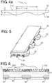
- Fig. 4a schematically shows for one embodiment of a diffusor 30 the relevant dimensions .
- the thickness d varies between a maximum thickness d 1 and a minimum thickness d 0 .
- the top surface 14a is plane, whereas the bottom surface 14b is undulating between maxima, corresponding to the first diffusion portions 30a, and minima, corresponding to the second diffusion portions 30b.
- the distance between the maxima is 1, which is equal to the pitch of the arrangement of the LEDs 20.
- the distance between maxima and minima is l 1 , which is equal to l/2.
- the thickness d varies continously in the example shown.
- the variation may be according to a sine function.
- the first diffusion portions 30a Due to the varying thickness of the diffusor 30, the first diffusion portions 30a cause a stronger diffusion effect than the thinner second diffusion portions 30b. Since the first diffusion portions 30a are arranged directly in front of the light emitting portions of the LEDs 20, the light 34a emitted therefrom perpendicular to the plane of the LEDs 20 is strongly diffused, whereas light 34b emitted under greater angles towards the second diffusion portions 30b undergoes a lower degree of diffusion. Overall, this leads to relatively homogeneous emission of light from the front surface 14a of the diffusor 30, i.e. to a uniform luminance.
- Fig. 4b shows a further embodiment of a diffusor 30 with in principle the same shape, but different dimensions.
- the ratio d 1 /d 0 is higher, such that the thickness maxima in this embodiment are steeper and more narrow as compared to the embodiment of Fig. 4a .
- the choice of the exact mathematical function of the thickness variation as well as the choice of dimension parameters d 0 , d 1 , and 1 may depend on the spread of the light emitted from the LEDs 20 as well as the distance between the LEDs 20 and the diffusor 30.
- the parameters may, for each application, be chosen to obtain the desired homogeneity value.
- Fig. 6 shows a longitudinal section of a second embodiment of a lighting assembly, which differs from the above described first embodiment by a different shape of the diffusor 31.
- the diffusor 31 has a constant thickness, but a varying density of diffusion particles (schematically shown in fig. 6 ).
- First diffusion portions 30a with a higher density of diffusion particles are arranged directly in front of the LEDs 20, whereas second diffusion portions 30b with a lower density of diffusion particles are arranged in between.
- the arrangement need not in all cases be equidistant, as long as the first diffusion portions 30a are arranged in front of the LEDs 20.
- the LEDs 20 shown in the above examples are packaged LEDs, it is also possible to use unpackaged LED dies.
Landscapes
- Engineering & Computer Science (AREA)
- General Engineering & Computer Science (AREA)
- Physics & Mathematics (AREA)
- Microelectronics & Electronic Packaging (AREA)
- Optics & Photonics (AREA)
- Led Device Packages (AREA)
- Non-Portable Lighting Devices Or Systems Thereof (AREA)
- Planar Illumination Modules (AREA)
Description
- The invention relates to the field of lighting, and more specifically to a lighting assembly.
- LEDs are used today for an increasing number of lighting applications due to advantageous properties such as high energy efficiency, compact size and long lifetime. However, while many lighting applications require light output to be spread over a larger area, the light output from LEDs is rather concentrated to small areas. If a plurality of LEDs is used, these are generally arranged at a certain distance from each other due to thermal limitations and for cost reasons.
- In order to obtain a relatively homogeneous light output from a plurality of LEDs, it is generally known to position a diffusor element in front of the LEDs. However, the arrangement of individual LEDs behind the diffusor is still visible in many cases, such that the light output over the front surface of the diffusor is not very homogeneous, leading to a spotty appearance. While a very thick diffusor may achieve better homogeneity, this will lead to reduced overall efficiency.
-
JP 2013 196847 A -
EP 1 028 348 A1 discloses an arrangement for producing a uniform illumination from a light source, for a surface to be illuminated, comprising a light source located behind a screen. The screen thickness varies over the surface cross section. -
WO 2008/025909 A1 discloses an optical system comprising a diffuser for a homogenized luminance output. - It could be considered an object to provide a lighting assembly for achieving a more homogeneous appearance, in particular with a compact arrangement.
- This is achieved by the lighting assembly according to claim 1. Dependent claims refer to preferred embodiments.
- According to the invention, at least two LED lighting elements are provided. The term "LED lighting elements" should be understood to cover any known type of solid state lighting element, such as e.g. light emitting diodes, organic light emitting diodes, laser diodes, etc. Each LED lighting element may comprise one or a plurality of such components arranged in proximity. For example, one LED lighting element may comprise two or more dies of light emitting diodes. In particular, it is possible to provide light emitting diodes of different color placed in proximity, such as e.g. in an RGB LED. The LED lighting elements may be individually packaged components, i.e. they may comprise individual housings with electrical terminals. Also, it is possible to provide the LED lighting elements as pure unpackaged LED dies, e.g. connected directly to a leadframe.
- The lighting assembly comprises at least two LED lighting elements, but a larger number is preferred, such as at least 3, 4 or 5, further preferably e.g. more than 10. The LED lighting elements are arranged at a distance from each other. While this is not required, a plurality of LED elements may be equally spaced. In particular, a plurality of LED lighting elements may be arranged in a line, e.g. equidistant according to a constant pitch.
- The lighting assembly according to the invention further comprises a diffusor element made from silicone and extending over the LED lighting elements, i.e. being arranged such that light therefrom is emitted into the direction of the diffusor element. The diffusor element is translucent but not entirely transparent, i.e. light traversing the diffusor element is scattered. For example, the diffusor element may comprise diffusion particles embedded in a transparent or translucent material, such as, for example, TiO2 particles dispersed in transparent.
- The inventors have considered that the light input from two or more LED lighting elements arranged at a distance from each other is inhomogeneous. Thus, in order to achieve a more homogeneous output from a top surface of the diffusor element, the optical properties of the diffusor element could be chosen non-homogeneous in order to counteract and compensate for the non-homogeneous light input. By a suitable choice of non-homogeneous optical properties of the diffusor element, light output may thus be homogenized.
- Accordingly, the diffusor element may be comprised of different diffusion portions providing different levels of optical diffusion in different locations. In the most basic configuration, at least two types of diffusion portions may be provided with different levels of diffusion. First diffusion portions may be arranged in front of the LED lighting elements, and at least one second diffusion portion may be arranged in between the first diffusion portions. The first diffusion portions are disposed to cause stronger optical diffusion than the second diffusion portion.
- Embodiments of a lighting assembly including such a non-homogeneous diffusor element with first and second diffusion portions have proven to provide a significantly homogenized light output as compared to a homogeneous diffusor element. A definition of the most preferred, fully homogeneous appearance would be a lambertian type emission of light from the surface with fully uniform luminance, i.e. no spatial variation. For practical embodiments of a light emitting surface, a homogeneity value may be defined as the standard deviation of the luminance values over the surface area divided by the mean luminance value over the surface area. Homogeneity values of e.g. 50%, preferably 40% or less may be regarded satisfactory for some applications. Values of 25% or less are preferered; especially preferred are values of 10% or less, which are generally perceived as fully homogeneous.
- In particular, satisfactory homogeneity values were obtained with the current invention already with a relatively thin diffusor element, thus maintaining high efficiency.
- The lighting assembly according to the invention is especially suited to provide line-shaped illumination, in particular in very compact assemblies. A plurality, or all, of the LED lighting elements may be arranged in a line. One or more diffusor elements may be provided to cover the LED lighting elements, being arranged such that first diffusion portions are each positioned in front of the LED lighting elements. Consequently, second diffusion portions may be arranged in between the LED lighting elements.
- While in principle an improvement in the homogeneity of the light output may be achieved with a stepwise variation of the level of optical diffusion changing between the first and second diffusion portions (with optionally intermediate portions in between), this is not preferred since steps may be visible in the luminance appearance. Therefore, it is generally preferred to provide a diffusor element where the level of optical diffusion varies continuously between the first and second diffusion portions. Preferably, the level of optical diffusion decreases monotonously from the first diffusion portions to the second diffusion portions.
- According to one embodiment, the diffusor element comprises diffusion particles embedded in a transparent or translucent material. In order to achieve the different levels of optical diffusion in the first and second diffusion portions (as well as optionally in any intermediate portions), the density of the diffusion particles may vary. The density in the first diffusion portions arranged in front of the LED lighting elements may be higher than the density in the second diffusion portions arranged in between the LED lighting elements.
- In a preferred embodiment, the different levels of optical diffusion in the first and second diffusion portions (as well as optionally any intermediate portions arranged in between the first and second diffusion portions) may be achieved by varying the thickness of the diffusor element. The thickness may e.g. be measured perpendicularly to a line or plane in which the LEDs are arranged. The first diffusion portions may be provided with a higher thickness than the second diffusion portions, such that light traversing the diffusor element at the first diffusion portions propagates a longer distance through the diffusor element in the first diffusion portions, thus undergoing stronger diffusion.
- A diffusor element of varying thickness may have a constant density of diffusion particles, which is easier to manufacture. However, it is also possible to combine a variation in particle density and a variation in thickness.
- Particularly in arrangements of LED elements along a line, the level of optical diffusion of an elongate diffusor element may vary along its length. If the LED elements are arranged at equal distances according to a first pitch, it is advantageous to provide a variation in the level of optical diffusion to be equally periodical with a second pitch equal to the first pitch. For example, the thickness of the diffusor element may vary periodically with the same pitch as the arrangement of the LED lighting elements, and preferably the arrangement of the LED lighting elements and of the thickness are spatially in phase, such that the maxima of the thickness are arranged directly above the LED lighting elements.
- In a preferred embodiment, a top surface of the diffusor element may have a plane shape. An opposed bottom surface oriented towards the LED lighting elements may have an undulating shape to obtain varying thickness.
- The variation of the thickness of the diffusor element may e.g. be such that first diffusion portions, e.g. corresponding to the maximum thickness, are at least 50% thicker than second diffusion portions, e.g. corresponding to the minimum thickness of the diffusor element. Further preferred, the first diffusion portions are at least 100% thicker than the second diffusion portions.
- According to the invention, the LED lighting elements are arranged with electrical conductors extending between them. In particular, a leadframe may connect the LED lighting elements.
- According to the invention, a flexible housing at least partly surrounding the LED lighting elements and the diffusor is provided. The housing may comprise reflective surfaces to improve efficiency. In particular, at least the inner surfaces of the housing oriented towards the LED lighting elements may be reflective. It is particularly preferred for a housing to cover the lateral and bottom surfaces of the lighting assembly, but not the top surface of the diffusor. The housing may be made of a flexible material, e.g. silicone.
- The lighting assembly according to the invention is particularly suited to be manufactured with very compact dimensions. For example, the height, e.g. measured from the bottom surface of the lighting assembly to a light emitting top surface of the diffusor may be less than 1 cm, further preferably equal to or less than 8 mm, particularly preferably 5 mm or less. Compared to the pitch of the LED elements, the height may be less than the pitch, preferably correspond to 50% or less of the pitch of the LED elements.
- These and other aspects of the invention will be apparent from and elucidated with reference to the embodiments described hereinafter.
- In the drawings,
-
Fig. 1 shows a perspective view of an embodiment of a lighting assembly; -
Fig. 2 shows a cross-sectional view of the lighting assembly ofFig. 1 with the section along A..A; -
Fig. 3 shows a longitudinal sectional view of the lighting assembly according tofig. 1, Fig. 2 ; -
Fig. 4a ,4b show a side views of different embodiments of diffusors of the lighting assembly according toFig. 1-Fig. 3 ; -
Fig. 5 shows a perspective view of some elements of the lighting assembly according toFig. 1-3 without a housing; -
Fig. 6 shows a longitudinal-sectional view of a second embodiment of a lighting assembly. - An
elongate lighting assembly 10 is shown infig. 1 , comprising abottom surface 12 and atop surface 14 from which light is emitted.Electrical connections 16 shown schematically deliver electrical operating power to thelighting assembly 10. - The
lighting assembly 10 is of particularly small dimensions, in a preferred example with a height measured from thebottom surface 12 to thetop surface 14 of only 4 mm and a width of only 7 mm. - The length in a longitudinal direction L may vary, but will be significantly greater than the width, e.g. at least 10 times greater.
- In the interior of the
lighting assembly 10, as shown in the cross-section offig. 2 and longitudinal-section offig. 3 , a plurality ofLEDs 20 are arranged in a line equally spaced along the longitudinal direction L of thelighting assembly 10. In the example shown, eachLED 20 comprises a LED die 22 surrounded by ahousing 24. TheLEDs 20 are electrically interconnected by electrical conductors forming aleadframe 26. - If supplied with electrical operating power, the
LEDs 20 are disposed to emit light into the direction of thetop surface 14, as schematically shown in dotted lines infig. 3 . The light from theLEDs 20 is emitted at thetop surface 14 through adiffusor 30. Thediffusor 30 is made of transparent silicone with dispersed TiO2 particles, such that the light emitted from theLEDs 20 is scattered and emitted as diffuse light from thetop surface 14 of the lighting assembly (or more specifically from atop surface 14a of he diffusor 30). - The
LEDs 20 and thediffusor 30 are enclosed by ahousing 28, covering the lateral sides and the bottom of thelighting assembly 10. The inner surfaces of thehousing 28 are reflective. The space between theLEDs 20 and thediffusor 30 is filled with a transparentlight guide 32, which may be made from silicone. - As shown in
fig. 3 , thediffusor 30 has a thickness d which varies along its length L.Thicker diffusor portions 30a are arranged directly in front of theLEDs 20, whereas thinnersecond diffusor portions 30b are arranged in between thefirst diffusor portions 30a, thus also in between theLEDs 20. -
Fig. 4a schematically shows for one embodiment of adiffusor 30 the relevant dimensions . The thickness d varies between a maximum thickness d1 and a minimum thickness d0. Thetop surface 14a is plane, whereas thebottom surface 14b is undulating between maxima, corresponding to thefirst diffusion portions 30a, and minima, corresponding to thesecond diffusion portions 30b. In the longitudinal direction L, the distance between the maxima is 1, which is equal to the pitch of the arrangement of theLEDs 20. The distance between maxima and minima is l1, which is equal to l/2. - Between the maxima and the minima, the thickness d varies continously in the example shown. For example, the variation may be according to a sine function.
- Due to the varying thickness of the
diffusor 30, thefirst diffusion portions 30a cause a stronger diffusion effect than the thinnersecond diffusion portions 30b. Since thefirst diffusion portions 30a are arranged directly in front of the light emitting portions of theLEDs 20, the light 34a emitted therefrom perpendicular to the plane of theLEDs 20 is strongly diffused, whereas light 34b emitted under greater angles towards thesecond diffusion portions 30b undergoes a lower degree of diffusion. Overall, this leads to relatively homogeneous emission of light from thefront surface 14a of thediffusor 30, i.e. to a uniform luminance. -
Fig. 4b shows a further embodiment of adiffusor 30 with in principle the same shape, but different dimensions. In particular, the ratio d1/d0 is higher, such that the thickness maxima in this embodiment are steeper and more narrow as compared to the embodiment ofFig. 4a . - In specific embodiments, the choice of the exact mathematical function of the thickness variation as well as the choice of dimension parameters d0, d1, and 1 may depend on the spread of the light emitted from the
LEDs 20 as well as the distance between theLEDs 20 and thediffusor 30. The parameters may, for each application, be chosen to obtain the desired homogeneity value. -
Fig. 6 shows a longitudinal section of a second embodiment of a lighting assembly, which differs from the above described first embodiment by a different shape of thediffusor 31. In the second embodiment, thediffusor 31 has a constant thickness, but a varying density of diffusion particles (schematically shown infig. 6 ).First diffusion portions 30a with a higher density of diffusion particles are arranged directly in front of theLEDs 20, whereassecond diffusion portions 30b with a lower density of diffusion particles are arranged in between. - Since the level of diffusion caused by the denser diffusion particles in the
first diffusion portions 30a is stronger than in thesecond diffusion portions 30b, this achieves the same effect of homogenizing the light output as described above. - While the invention has been illustrated and described in detail in the drawings and foregoing description, such illustration and description are to be considered illustrative or examplary and not restrictive; the invention is not limited to the disclosed embodiments.
- For example, while the above embodiments show a constant pitch both for the variations in the
diffusor 30 and the placement of theLEDs 20, the arrangement need not in all cases be equidistant, as long as thefirst diffusion portions 30a are arranged in front of theLEDs 20. While theLEDs 20 shown in the above examples are packaged LEDs, it is also possible to use unpackaged LED dies. - Other variations to the disclosed embodiment can be understood and effected by those skilled in the art in practicing the claimed invention, from a study of the drawings, the disclosure and the appended claims.
- In the claims, the word "comprising" does not exclude other elements, and the indefinit article "a" or "an" does not exclude a plurality.
- The mere fact that certain measures are recited in mutually different dependent claims or embodiments does not indicate that a combination of these measures cannot be used to advantage. For example, it is possible to combine a variation in thickness with a variation in the density of diffusion particles.
- Any reference signs in the claims should not be construed as limiting the scope.
Claims (13)
- Lighting assembly, including- at least two LED lighting elements (20) arranged at a distance from each other,- a diffusor element (30) extending over said LED lighting elements (20), said diffusor element (30) comprising at least first diffusion portions (30a) arranged in front of said LED lighting elements (30) and at least one second diffusion portion (30b) arranged in between said first diffusion portions (30a), said first diffusion portions (30a) being disposed to cause a stronger optical diffusion than said second diffusion portions (30b), and
wherein the diffusor element (30) is made from silicone,
wherein said LED lighting elements (20) and said diffusor element (30) are at least partly surrounded by a flexible housing (28), and
wherein electrical conductors (26) are arranged between said LED lighting elements (20). - Lighting assembly according to claim 1, wherein- a plurality of said LED lighting elements (30) are arranged in a line,- said first diffusion portions (30a) being each arranged in front of said LED lighting elements (20).
- Lighting assembly according to one of the above claims, wherein- said diffusor element (30) is disposed such that a level of optical diffusion varies continuously between said first and second diffusion portions (30a, 30b).
- Lighting assembly according to one of the above claims, wherein- said diffusor element (30) comprises diffusion particles embedded in a transparent or translucent material,- wherein a density of said diffusion particles in said first diffusion portions (30a) is higher than said density in said second diffusion portions (30b).
- Lighting assembly according to one of the above claims, wherein- a thickness (d) of said diffusor element (30) in said first diffusion portions (30a) is greater than said thickness (d) in said second diffusion portions (30b).
- Lighting assembly according to claim 5, wherein- said LED elements (20) are arranged along a line at equal distances according to a first pitch,- and said thickness (d) varies periodically with a second pitch equal to said first pitch.
- Lighting assembly according to one of claims 5, 6, wherein- a bottom surface (14b) of said diffusor element (30) oriented towards said LED lighting elements (20) has an undulating shape,- and a top surface of said diffusor element (30), arranged opposite of said bottom surface, has a plane shape.
- Lighting assembly according to one of claims 5 - 7, wherein- said thickness (d1) in said first diffusion portions (30a) is at least 50% greater than said thickness (d0) in said second diffusion portions (30b).
- Lighting assembly according to claim 1, wherein- said LED lighting elements (20) are electrically interconnected by electrical conductors forming a lead-frame 26.
- Lighting assembly according to one of the above claims, wherein- a light guide (32) is arranged between said LED elements (20) and said diffusor element (30).
- Lighting assembly according to claim 10, wherein- the light guide is made from silicone.
- Lighting assembly according to one of the above claims, wherein- a height, measured from a bottom surface (12) to a top surface of said diffusor (14a) is less than a pitch between said LED elements (20).
- Lighting assembly according to one of the above claims, wherein- a height, measured from a bottom surface (12) to a top surface (14a) of said diffusor element (30), is less than 1 cm.
Applications Claiming Priority (2)
| Application Number | Priority Date | Filing Date | Title |
|---|---|---|---|
| EP16191317 | 2016-09-29 | ||
| PCT/EP2017/073322 WO2018059973A1 (en) | 2016-09-29 | 2017-09-15 | Lighting assembly with diffusor |
Publications (2)
| Publication Number | Publication Date |
|---|---|
| EP3519728A1 EP3519728A1 (en) | 2019-08-07 |
| EP3519728B1 true EP3519728B1 (en) | 2020-07-29 |
Family
ID=57123809
Family Applications (1)
| Application Number | Title | Priority Date | Filing Date |
|---|---|---|---|
| EP17772647.8A Active EP3519728B1 (en) | 2016-09-29 | 2017-09-15 | Lighting assembly with diffusor |
Country Status (6)
| Country | Link |
|---|---|
| US (1) | US10845025B2 (en) |
| EP (1) | EP3519728B1 (en) |
| JP (1) | JP7145148B2 (en) |
| KR (1) | KR102432261B1 (en) |
| CN (1) | CN109790963B (en) |
| WO (1) | WO2018059973A1 (en) |
Families Citing this family (4)
| Publication number | Priority date | Publication date | Assignee | Title |
|---|---|---|---|---|
| DE102017215369A1 (en) * | 2017-09-01 | 2019-03-07 | Benecke-Kaliko Ag | Translucent multi-layer composite film |
| US11125395B2 (en) * | 2019-08-15 | 2021-09-21 | Luminii Llc | Lighting system providing combined directional and ambient light |
| DE102021214575A1 (en) | 2021-12-17 | 2023-06-22 | Volkswagen Aktiengesellschaft | Lighting device for emitting light and vehicle |
| US12123585B1 (en) * | 2023-09-28 | 2024-10-22 | Signcomplex Limited | Silicone co-extrusion method for LED light strip, mold and its extrusion structure |
Family Cites Families (31)
| Publication number | Priority date | Publication date | Assignee | Title |
|---|---|---|---|---|
| JPH03208205A (en) * | 1990-01-11 | 1991-09-11 | Shin Etsu Polymer Co Ltd | Lighting device |
| WO2000013057A1 (en) | 1998-08-28 | 2000-03-09 | Citizen Watch Co., Ltd. | Liquid crystal display and method of driving the same |
| DE19905217A1 (en) * | 1999-02-09 | 2000-08-10 | Mannesmann Vdo Ag | Device for equalizing the illumination of a surface |
| JP2003535437A (en) * | 2000-04-28 | 2003-11-25 | ゼネラル・エレクトリック・カンパニイ | Safety lamp |
| JP3075996U (en) * | 2000-08-30 | 2001-03-16 | 舶用電球株式会社 | Tube type LED lamp |
| JP2003177379A (en) * | 2001-12-10 | 2003-06-27 | Hitachi Ltd | Liquid crystal display |
| US6846098B2 (en) * | 2002-05-16 | 2005-01-25 | Eastman Kodak Company | Light diffuser with variable diffusion |
| WO2004070262A2 (en) * | 2003-02-04 | 2004-08-19 | Ilight Technologies, Inc. | Flexible illumination device for simulating neon lighting |
| US7048413B2 (en) * | 2003-08-14 | 2006-05-23 | Ben Fan | Light string using a cladding to scatter light from light emitting diodes to present a neon light effect |
| JP2007036044A (en) * | 2005-07-28 | 2007-02-08 | Mitsubishi Rayon Co Ltd | Surface light source device |
| FR2905479B1 (en) | 2006-08-31 | 2008-10-31 | Saint Gobain | OPTICAL SYSTEM FOR LIGHTING DEVICE, LIGHTING DEVICE AND DEVICE CONTROLLING METHOD |
| CN101479525B (en) * | 2006-10-27 | 2012-02-08 | 夏普株式会社 | Lighting device and liquid crystal display device |
| KR100992460B1 (en) * | 2008-05-29 | 2010-11-08 | 주식회사신도리코 | LED light source assembly capable of uniform irradiation and its manufacturing method |
| KR20100054700A (en) * | 2008-11-14 | 2010-05-25 | 엘지디스플레이 주식회사 | Backlight unit |
| JP2010192246A (en) * | 2009-02-18 | 2010-09-02 | Toppan Printing Co Ltd | Light diffusion plate, optical sheet, backlight unit, and display device |
| WO2010123284A2 (en) * | 2009-04-21 | 2010-10-28 | Lg Electronics Inc. | Light emitting device |
| KR20110117458A (en) * | 2010-04-21 | 2011-10-27 | 엘지전자 주식회사 | Display device |
| JP5423703B2 (en) * | 2010-07-08 | 2014-02-19 | 信越化学工業株式会社 | Light diffusion member for lighting equipment |
| JP5931895B2 (en) * | 2010-11-10 | 2016-06-08 | エルジー イノテック カンパニー リミテッド | Lighting unit |
| US8827487B2 (en) * | 2010-12-28 | 2014-09-09 | Bridgelux, Inc. | Gradient optics for controllable light distribution for LED light sources |
| JP5512744B2 (en) * | 2011-10-31 | 2014-06-04 | エイテックス株式会社 | Circuit board for LED mounting, strip-shaped flexible LED light, and LED lighting device using the same |
| KR101308590B1 (en) * | 2011-12-07 | 2013-09-13 | 김태윤 | LED lighting apparatus of band type |
| JP5783940B2 (en) * | 2012-03-16 | 2015-09-24 | 三菱電機照明株式会社 | LED lamp |
| KR101906893B1 (en) * | 2012-04-27 | 2018-10-11 | 삼성전자주식회사 | Light emitting device |
| CN103672568A (en) * | 2012-09-04 | 2014-03-26 | 展晶科技(深圳)有限公司 | Direct type backlight module |
| DE102012222476A1 (en) * | 2012-12-06 | 2014-06-12 | Osram Gmbh | Lighting device with optoelectronic component |
| US10655790B2 (en) * | 2014-01-30 | 2020-05-19 | Signify Holding B.V. | Lighting device |
| JP6188611B2 (en) * | 2014-03-20 | 2017-08-30 | 三菱電機株式会社 | Lighting device |
| US9927092B2 (en) * | 2014-10-31 | 2018-03-27 | Itc Incorporated | LED linear light assembly with reflectance members |
| JP2016126951A (en) * | 2015-01-07 | 2016-07-11 | 日立アプライアンス株式会社 | Cover for led lighting and luminaire using the same |
| KR20170106575A (en) * | 2016-03-11 | 2017-09-21 | 삼성전자주식회사 | Light source module and lighting apparatus having the same |
-
2017
- 2017-09-15 CN CN201780060695.4A patent/CN109790963B/en active Active
- 2017-09-15 WO PCT/EP2017/073322 patent/WO2018059973A1/en not_active Ceased
- 2017-09-15 KR KR1020197012200A patent/KR102432261B1/en active Active
- 2017-09-15 EP EP17772647.8A patent/EP3519728B1/en active Active
- 2017-09-15 US US16/336,287 patent/US10845025B2/en active Active
- 2017-09-15 JP JP2019516376A patent/JP7145148B2/en active Active
Non-Patent Citations (1)
| Title |
|---|
| None * |
Also Published As
| Publication number | Publication date |
|---|---|
| US20190277476A1 (en) | 2019-09-12 |
| JP2019530174A (en) | 2019-10-17 |
| JP7145148B2 (en) | 2022-09-30 |
| WO2018059973A1 (en) | 2018-04-05 |
| CN109790963B (en) | 2022-08-26 |
| CN109790963A (en) | 2019-05-21 |
| EP3519728A1 (en) | 2019-08-07 |
| US10845025B2 (en) | 2020-11-24 |
| KR102432261B1 (en) | 2022-08-16 |
| KR20190061039A (en) | 2019-06-04 |
Similar Documents
| Publication | Publication Date | Title |
|---|---|---|
| EP2447599B1 (en) | Lighting apparatus | |
| KR101231484B1 (en) | Light source adapted for lcd back-lit displays | |
| US10845025B2 (en) | Lighting assembly with diffusor | |
| US9557465B2 (en) | Illuminator | |
| EP2672513B1 (en) | Multichip package structure for generating a symmetrical and uniform light-blending source | |
| EP2405182A2 (en) | Light emitting device | |
| CN204573617U (en) | Lighting device | |
| KR20100040839A (en) | Thin luminaire for general lighting applications | |
| US9404626B2 (en) | Illuminating apparatus | |
| US20100117100A1 (en) | Light-emitting module and illumination device | |
| CN204534161U (en) | Lighting device | |
| US20180149320A1 (en) | Light-emitting diode type lighting device | |
| JP6558672B2 (en) | LED module and lighting apparatus | |
| JPWO2016125511A1 (en) | Lighting device | |
| CN204534162U (en) | Lighting device | |
| JP6198120B2 (en) | Light emitting module and lighting device using the same | |
| KR20180129110A (en) | LED electric light module | |
| JP6616050B1 (en) | Lamp with floating light source | |
| CN104075155A (en) | Lamps and lighting fixtures | |
| JP2014187095A (en) | Led module and illumination device | |
| JP6276676B2 (en) | Light guide member, light emitter and signboard | |
| JP2022155935A (en) | Light guide plate, and, lighting apparatus | |
| JP6138705B2 (en) | Lighting device and display device | |
| US20160010810A1 (en) | Illumination device | |
| JP2025110105A (en) | Lighting equipment |
Legal Events
| Date | Code | Title | Description |
|---|---|---|---|
| STAA | Information on the status of an ep patent application or granted ep patent |
Free format text: STATUS: UNKNOWN |
|
| STAA | Information on the status of an ep patent application or granted ep patent |
Free format text: STATUS: THE INTERNATIONAL PUBLICATION HAS BEEN MADE |
|
| PUAI | Public reference made under article 153(3) epc to a published international application that has entered the european phase |
Free format text: ORIGINAL CODE: 0009012 |
|
| STAA | Information on the status of an ep patent application or granted ep patent |
Free format text: STATUS: REQUEST FOR EXAMINATION WAS MADE |
|
| 17P | Request for examination filed |
Effective date: 20190429 |
|
| AK | Designated contracting states |
Kind code of ref document: A1 Designated state(s): AL AT BE BG CH CY CZ DE DK EE ES FI FR GB GR HR HU IE IS IT LI LT LU LV MC MK MT NL NO PL PT RO RS SE SI SK SM TR |
|
| AX | Request for extension of the european patent |
Extension state: BA ME |
|
| DAV | Request for validation of the european patent (deleted) | ||
| DAX | Request for extension of the european patent (deleted) | ||
| REG | Reference to a national code |
Ref country code: DE Ref legal event code: R079 Ref document number: 602017020681 Country of ref document: DE Free format text: PREVIOUS MAIN CLASS: F21V0003040000 Ipc: F21S0004280000 |
|
| RIC1 | Information provided on ipc code assigned before grant |
Ipc: F21Y 115/10 20160101ALN20200131BHEP Ipc: F21S 4/28 20160101AFI20200131BHEP Ipc: F21V 3/06 20180101ALI20200131BHEP Ipc: F21Y 103/10 20160101ALN20200131BHEP |
|
| GRAP | Despatch of communication of intention to grant a patent |
Free format text: ORIGINAL CODE: EPIDOSNIGR1 |
|
| STAA | Information on the status of an ep patent application or granted ep patent |
Free format text: STATUS: GRANT OF PATENT IS INTENDED |
|
| RIC1 | Information provided on ipc code assigned before grant |
Ipc: F21S 4/28 20160101AFI20200225BHEP Ipc: F21Y 103/10 20160101ALN20200225BHEP Ipc: F21V 3/06 20180101ALI20200225BHEP Ipc: F21Y 115/10 20160101ALN20200225BHEP |
|
| RIC1 | Information provided on ipc code assigned before grant |
Ipc: F21S 4/28 20160101AFI20200305BHEP Ipc: F21Y 103/10 20160101ALN20200305BHEP Ipc: F21Y 115/10 20160101ALN20200305BHEP Ipc: F21V 3/06 20180101ALI20200305BHEP |
|
| INTG | Intention to grant announced |
Effective date: 20200325 |
|
| GRAS | Grant fee paid |
Free format text: ORIGINAL CODE: EPIDOSNIGR3 |
|
| GRAA | (expected) grant |
Free format text: ORIGINAL CODE: 0009210 |
|
| STAA | Information on the status of an ep patent application or granted ep patent |
Free format text: STATUS: THE PATENT HAS BEEN GRANTED |
|
| AK | Designated contracting states |
Kind code of ref document: B1 Designated state(s): AL AT BE BG CH CY CZ DE DK EE ES FI FR GB GR HR HU IE IS IT LI LT LU LV MC MK MT NL NO PL PT RO RS SE SI SK SM TR |
|
| REG | Reference to a national code |
Ref country code: CH Ref legal event code: EP |
|
| REG | Reference to a national code |
Ref country code: AT Ref legal event code: REF Ref document number: 1296222 Country of ref document: AT Kind code of ref document: T Effective date: 20200815 |
|
| REG | Reference to a national code |
Ref country code: IE Ref legal event code: FG4D |
|
| REG | Reference to a national code |
Ref country code: DE Ref legal event code: R096 Ref document number: 602017020681 Country of ref document: DE |
|
| REG | Reference to a national code |
Ref country code: LT Ref legal event code: MG4D |
|
| REG | Reference to a national code |
Ref country code: NL Ref legal event code: MP Effective date: 20200729 |
|
| REG | Reference to a national code |
Ref country code: AT Ref legal event code: MK05 Ref document number: 1296222 Country of ref document: AT Kind code of ref document: T Effective date: 20200729 |
|
| PG25 | Lapsed in a contracting state [announced via postgrant information from national office to epo] |
Ref country code: ES Free format text: LAPSE BECAUSE OF FAILURE TO SUBMIT A TRANSLATION OF THE DESCRIPTION OR TO PAY THE FEE WITHIN THE PRESCRIBED TIME-LIMIT Effective date: 20200729 Ref country code: GR Free format text: LAPSE BECAUSE OF FAILURE TO SUBMIT A TRANSLATION OF THE DESCRIPTION OR TO PAY THE FEE WITHIN THE PRESCRIBED TIME-LIMIT Effective date: 20201030 Ref country code: BG Free format text: LAPSE BECAUSE OF FAILURE TO SUBMIT A TRANSLATION OF THE DESCRIPTION OR TO PAY THE FEE WITHIN THE PRESCRIBED TIME-LIMIT Effective date: 20201029 Ref country code: LT Free format text: LAPSE BECAUSE OF FAILURE TO SUBMIT A TRANSLATION OF THE DESCRIPTION OR TO PAY THE FEE WITHIN THE PRESCRIBED TIME-LIMIT Effective date: 20200729 Ref country code: AT Free format text: LAPSE BECAUSE OF FAILURE TO SUBMIT A TRANSLATION OF THE DESCRIPTION OR TO PAY THE FEE WITHIN THE PRESCRIBED TIME-LIMIT Effective date: 20200729 Ref country code: HR Free format text: LAPSE BECAUSE OF FAILURE TO SUBMIT A TRANSLATION OF THE DESCRIPTION OR TO PAY THE FEE WITHIN THE PRESCRIBED TIME-LIMIT Effective date: 20200729 Ref country code: NO Free format text: LAPSE BECAUSE OF FAILURE TO SUBMIT A TRANSLATION OF THE DESCRIPTION OR TO PAY THE FEE WITHIN THE PRESCRIBED TIME-LIMIT Effective date: 20201029 Ref country code: FI Free format text: LAPSE BECAUSE OF FAILURE TO SUBMIT A TRANSLATION OF THE DESCRIPTION OR TO PAY THE FEE WITHIN THE PRESCRIBED TIME-LIMIT Effective date: 20200729 Ref country code: PT Free format text: LAPSE BECAUSE OF FAILURE TO SUBMIT A TRANSLATION OF THE DESCRIPTION OR TO PAY THE FEE WITHIN THE PRESCRIBED TIME-LIMIT Effective date: 20201130 Ref country code: SE Free format text: LAPSE BECAUSE OF FAILURE TO SUBMIT A TRANSLATION OF THE DESCRIPTION OR TO PAY THE FEE WITHIN THE PRESCRIBED TIME-LIMIT Effective date: 20200729 |
|
| PG25 | Lapsed in a contracting state [announced via postgrant information from national office to epo] |
Ref country code: RS Free format text: LAPSE BECAUSE OF FAILURE TO SUBMIT A TRANSLATION OF THE DESCRIPTION OR TO PAY THE FEE WITHIN THE PRESCRIBED TIME-LIMIT Effective date: 20200729 Ref country code: PL Free format text: LAPSE BECAUSE OF FAILURE TO SUBMIT A TRANSLATION OF THE DESCRIPTION OR TO PAY THE FEE WITHIN THE PRESCRIBED TIME-LIMIT Effective date: 20200729 Ref country code: LV Free format text: LAPSE BECAUSE OF FAILURE TO SUBMIT A TRANSLATION OF THE DESCRIPTION OR TO PAY THE FEE WITHIN THE PRESCRIBED TIME-LIMIT Effective date: 20200729 Ref country code: IS Free format text: LAPSE BECAUSE OF FAILURE TO SUBMIT A TRANSLATION OF THE DESCRIPTION OR TO PAY THE FEE WITHIN THE PRESCRIBED TIME-LIMIT Effective date: 20201129 |
|
| PG25 | Lapsed in a contracting state [announced via postgrant information from national office to epo] |
Ref country code: NL Free format text: LAPSE BECAUSE OF FAILURE TO SUBMIT A TRANSLATION OF THE DESCRIPTION OR TO PAY THE FEE WITHIN THE PRESCRIBED TIME-LIMIT Effective date: 20200729 |
|
| PG25 | Lapsed in a contracting state [announced via postgrant information from national office to epo] |
Ref country code: CZ Free format text: LAPSE BECAUSE OF FAILURE TO SUBMIT A TRANSLATION OF THE DESCRIPTION OR TO PAY THE FEE WITHIN THE PRESCRIBED TIME-LIMIT Effective date: 20200729 Ref country code: DK Free format text: LAPSE BECAUSE OF FAILURE TO SUBMIT A TRANSLATION OF THE DESCRIPTION OR TO PAY THE FEE WITHIN THE PRESCRIBED TIME-LIMIT Effective date: 20200729 Ref country code: RO Free format text: LAPSE BECAUSE OF FAILURE TO SUBMIT A TRANSLATION OF THE DESCRIPTION OR TO PAY THE FEE WITHIN THE PRESCRIBED TIME-LIMIT Effective date: 20200729 Ref country code: EE Free format text: LAPSE BECAUSE OF FAILURE TO SUBMIT A TRANSLATION OF THE DESCRIPTION OR TO PAY THE FEE WITHIN THE PRESCRIBED TIME-LIMIT Effective date: 20200729 Ref country code: SM Free format text: LAPSE BECAUSE OF FAILURE TO SUBMIT A TRANSLATION OF THE DESCRIPTION OR TO PAY THE FEE WITHIN THE PRESCRIBED TIME-LIMIT Effective date: 20200729 Ref country code: IT Free format text: LAPSE BECAUSE OF FAILURE TO SUBMIT A TRANSLATION OF THE DESCRIPTION OR TO PAY THE FEE WITHIN THE PRESCRIBED TIME-LIMIT Effective date: 20200729 |
|
| REG | Reference to a national code |
Ref country code: CH Ref legal event code: PL Ref country code: DE Ref legal event code: R097 Ref document number: 602017020681 Country of ref document: DE |
|
| PG25 | Lapsed in a contracting state [announced via postgrant information from national office to epo] |
Ref country code: AL Free format text: LAPSE BECAUSE OF FAILURE TO SUBMIT A TRANSLATION OF THE DESCRIPTION OR TO PAY THE FEE WITHIN THE PRESCRIBED TIME-LIMIT Effective date: 20200729 |
|
| PLBE | No opposition filed within time limit |
Free format text: ORIGINAL CODE: 0009261 |
|
| STAA | Information on the status of an ep patent application or granted ep patent |
Free format text: STATUS: NO OPPOSITION FILED WITHIN TIME LIMIT |
|
| REG | Reference to a national code |
Ref country code: BE Ref legal event code: MM Effective date: 20200930 |
|
| PG25 | Lapsed in a contracting state [announced via postgrant information from national office to epo] |
Ref country code: LU Free format text: LAPSE BECAUSE OF NON-PAYMENT OF DUE FEES Effective date: 20200915 Ref country code: SK Free format text: LAPSE BECAUSE OF FAILURE TO SUBMIT A TRANSLATION OF THE DESCRIPTION OR TO PAY THE FEE WITHIN THE PRESCRIBED TIME-LIMIT Effective date: 20200729 |
|
| 26N | No opposition filed |
Effective date: 20210430 |
|
| PG25 | Lapsed in a contracting state [announced via postgrant information from national office to epo] |
Ref country code: CH Free format text: LAPSE BECAUSE OF NON-PAYMENT OF DUE FEES Effective date: 20200930 Ref country code: BE Free format text: LAPSE BECAUSE OF NON-PAYMENT OF DUE FEES Effective date: 20200930 Ref country code: SI Free format text: LAPSE BECAUSE OF FAILURE TO SUBMIT A TRANSLATION OF THE DESCRIPTION OR TO PAY THE FEE WITHIN THE PRESCRIBED TIME-LIMIT Effective date: 20200729 Ref country code: IE Free format text: LAPSE BECAUSE OF NON-PAYMENT OF DUE FEES Effective date: 20200915 Ref country code: LI Free format text: LAPSE BECAUSE OF NON-PAYMENT OF DUE FEES Effective date: 20200930 |
|
| PG25 | Lapsed in a contracting state [announced via postgrant information from national office to epo] |
Ref country code: TR Free format text: LAPSE BECAUSE OF FAILURE TO SUBMIT A TRANSLATION OF THE DESCRIPTION OR TO PAY THE FEE WITHIN THE PRESCRIBED TIME-LIMIT Effective date: 20200729 Ref country code: MT Free format text: LAPSE BECAUSE OF FAILURE TO SUBMIT A TRANSLATION OF THE DESCRIPTION OR TO PAY THE FEE WITHIN THE PRESCRIBED TIME-LIMIT Effective date: 20200729 Ref country code: CY Free format text: LAPSE BECAUSE OF FAILURE TO SUBMIT A TRANSLATION OF THE DESCRIPTION OR TO PAY THE FEE WITHIN THE PRESCRIBED TIME-LIMIT Effective date: 20200729 |
|
| PG25 | Lapsed in a contracting state [announced via postgrant information from national office to epo] |
Ref country code: MK Free format text: LAPSE BECAUSE OF FAILURE TO SUBMIT A TRANSLATION OF THE DESCRIPTION OR TO PAY THE FEE WITHIN THE PRESCRIBED TIME-LIMIT Effective date: 20200729 Ref country code: MC Free format text: LAPSE BECAUSE OF FAILURE TO SUBMIT A TRANSLATION OF THE DESCRIPTION OR TO PAY THE FEE WITHIN THE PRESCRIBED TIME-LIMIT Effective date: 20200729 |
|
| P01 | Opt-out of the competence of the unified patent court (upc) registered |
Effective date: 20230530 |
|
| PGFP | Annual fee paid to national office [announced via postgrant information from national office to epo] |
Ref country code: DE Payment date: 20250926 Year of fee payment: 9 |
|
| PGFP | Annual fee paid to national office [announced via postgrant information from national office to epo] |
Ref country code: GB Payment date: 20250923 Year of fee payment: 9 |
|
| PGFP | Annual fee paid to national office [announced via postgrant information from national office to epo] |
Ref country code: FR Payment date: 20250925 Year of fee payment: 9 |