EP3519715B1 - A vehicle disc brake assembly comprising elastic bushings - Google Patents
A vehicle disc brake assembly comprising elastic bushings Download PDFInfo
- Publication number
- EP3519715B1 EP3519715B1 EP17857267.3A EP17857267A EP3519715B1 EP 3519715 B1 EP3519715 B1 EP 3519715B1 EP 17857267 A EP17857267 A EP 17857267A EP 3519715 B1 EP3519715 B1 EP 3519715B1
- Authority
- EP
- European Patent Office
- Prior art keywords
- guide rod
- bore
- bushing
- fastener
- brake assembly
- Prior art date
- Legal status (The legal status is an assumption and is not a legal conclusion. Google has not performed a legal analysis and makes no representation as to the accuracy of the status listed.)
- Active
Links
Images




Classifications
-
- F—MECHANICAL ENGINEERING; LIGHTING; HEATING; WEAPONS; BLASTING
- F16—ENGINEERING ELEMENTS AND UNITS; GENERAL MEASURES FOR PRODUCING AND MAINTAINING EFFECTIVE FUNCTIONING OF MACHINES OR INSTALLATIONS; THERMAL INSULATION IN GENERAL
- F16D—COUPLINGS FOR TRANSMITTING ROTATION; CLUTCHES; BRAKES
- F16D65/00—Parts or details
- F16D65/0006—Noise or vibration control
-
- F—MECHANICAL ENGINEERING; LIGHTING; HEATING; WEAPONS; BLASTING
- F16—ENGINEERING ELEMENTS AND UNITS; GENERAL MEASURES FOR PRODUCING AND MAINTAINING EFFECTIVE FUNCTIONING OF MACHINES OR INSTALLATIONS; THERMAL INSULATION IN GENERAL
- F16D—COUPLINGS FOR TRANSMITTING ROTATION; CLUTCHES; BRAKES
- F16D55/00—Brakes with substantially-radial braking surfaces pressed together in axial direction, e.g. disc brakes
- F16D55/02—Brakes with substantially-radial braking surfaces pressed together in axial direction, e.g. disc brakes with axially-movable discs or pads pressed against axially-located rotating members
- F16D55/22—Brakes with substantially-radial braking surfaces pressed together in axial direction, e.g. disc brakes with axially-movable discs or pads pressed against axially-located rotating members by clamping an axially-located rotating disc between movable braking members, e.g. movable brake discs or brake pads
- F16D55/224—Brakes with substantially-radial braking surfaces pressed together in axial direction, e.g. disc brakes with axially-movable discs or pads pressed against axially-located rotating members by clamping an axially-located rotating disc between movable braking members, e.g. movable brake discs or brake pads with a common actuating member for the braking members
- F16D55/225—Brakes with substantially-radial braking surfaces pressed together in axial direction, e.g. disc brakes with axially-movable discs or pads pressed against axially-located rotating members by clamping an axially-located rotating disc between movable braking members, e.g. movable brake discs or brake pads with a common actuating member for the braking members the braking members being brake pads
- F16D55/226—Brakes with substantially-radial braking surfaces pressed together in axial direction, e.g. disc brakes with axially-movable discs or pads pressed against axially-located rotating members by clamping an axially-located rotating disc between movable braking members, e.g. movable brake discs or brake pads with a common actuating member for the braking members the braking members being brake pads in which the common actuating member is moved axially, e.g. floating caliper disc brakes
- F16D55/2265—Brakes with substantially-radial braking surfaces pressed together in axial direction, e.g. disc brakes with axially-movable discs or pads pressed against axially-located rotating members by clamping an axially-located rotating disc between movable braking members, e.g. movable brake discs or brake pads with a common actuating member for the braking members the braking members being brake pads in which the common actuating member is moved axially, e.g. floating caliper disc brakes the axial movement being guided by one or more pins engaging bores in the brake support or the brake housing
-
- F—MECHANICAL ENGINEERING; LIGHTING; HEATING; WEAPONS; BLASTING
- F16—ENGINEERING ELEMENTS AND UNITS; GENERAL MEASURES FOR PRODUCING AND MAINTAINING EFFECTIVE FUNCTIONING OF MACHINES OR INSTALLATIONS; THERMAL INSULATION IN GENERAL
- F16D—COUPLINGS FOR TRANSMITTING ROTATION; CLUTCHES; BRAKES
- F16D55/00—Brakes with substantially-radial braking surfaces pressed together in axial direction, e.g. disc brakes
- F16D55/02—Brakes with substantially-radial braking surfaces pressed together in axial direction, e.g. disc brakes with axially-movable discs or pads pressed against axially-located rotating members
- F16D55/22—Brakes with substantially-radial braking surfaces pressed together in axial direction, e.g. disc brakes with axially-movable discs or pads pressed against axially-located rotating members by clamping an axially-located rotating disc between movable braking members, e.g. movable brake discs or brake pads
- F16D55/224—Brakes with substantially-radial braking surfaces pressed together in axial direction, e.g. disc brakes with axially-movable discs or pads pressed against axially-located rotating members by clamping an axially-located rotating disc between movable braking members, e.g. movable brake discs or brake pads with a common actuating member for the braking members
- F16D55/225—Brakes with substantially-radial braking surfaces pressed together in axial direction, e.g. disc brakes with axially-movable discs or pads pressed against axially-located rotating members by clamping an axially-located rotating disc between movable braking members, e.g. movable brake discs or brake pads with a common actuating member for the braking members the braking members being brake pads
- F16D55/226—Brakes with substantially-radial braking surfaces pressed together in axial direction, e.g. disc brakes with axially-movable discs or pads pressed against axially-located rotating members by clamping an axially-located rotating disc between movable braking members, e.g. movable brake discs or brake pads with a common actuating member for the braking members the braking members being brake pads in which the common actuating member is moved axially, e.g. floating caliper disc brakes
- F16D55/2265—Brakes with substantially-radial braking surfaces pressed together in axial direction, e.g. disc brakes with axially-movable discs or pads pressed against axially-located rotating members by clamping an axially-located rotating disc between movable braking members, e.g. movable brake discs or brake pads with a common actuating member for the braking members the braking members being brake pads in which the common actuating member is moved axially, e.g. floating caliper disc brakes the axial movement being guided by one or more pins engaging bores in the brake support or the brake housing
- F16D55/22655—Constructional details of guide pins
-
- F—MECHANICAL ENGINEERING; LIGHTING; HEATING; WEAPONS; BLASTING
- F16—ENGINEERING ELEMENTS AND UNITS; GENERAL MEASURES FOR PRODUCING AND MAINTAINING EFFECTIVE FUNCTIONING OF MACHINES OR INSTALLATIONS; THERMAL INSULATION IN GENERAL
- F16D—COUPLINGS FOR TRANSMITTING ROTATION; CLUTCHES; BRAKES
- F16D65/00—Parts or details
- F16D65/005—Components of axially engaging brakes not otherwise provided for
- F16D65/0087—Brake housing guide members, e.g. caliper pins; Accessories therefor, e.g. dust boots
-
- F—MECHANICAL ENGINEERING; LIGHTING; HEATING; WEAPONS; BLASTING
- F16—ENGINEERING ELEMENTS AND UNITS; GENERAL MEASURES FOR PRODUCING AND MAINTAINING EFFECTIVE FUNCTIONING OF MACHINES OR INSTALLATIONS; THERMAL INSULATION IN GENERAL
- F16D—COUPLINGS FOR TRANSMITTING ROTATION; CLUTCHES; BRAKES
- F16D55/00—Brakes with substantially-radial braking surfaces pressed together in axial direction, e.g. disc brakes
- F16D55/02—Brakes with substantially-radial braking surfaces pressed together in axial direction, e.g. disc brakes with axially-movable discs or pads pressed against axially-located rotating members
- F16D55/22—Brakes with substantially-radial braking surfaces pressed together in axial direction, e.g. disc brakes with axially-movable discs or pads pressed against axially-located rotating members by clamping an axially-located rotating disc between movable braking members, e.g. movable brake discs or brake pads
- F16D55/224—Brakes with substantially-radial braking surfaces pressed together in axial direction, e.g. disc brakes with axially-movable discs or pads pressed against axially-located rotating members by clamping an axially-located rotating disc between movable braking members, e.g. movable brake discs or brake pads with a common actuating member for the braking members
- F16D55/225—Brakes with substantially-radial braking surfaces pressed together in axial direction, e.g. disc brakes with axially-movable discs or pads pressed against axially-located rotating members by clamping an axially-located rotating disc between movable braking members, e.g. movable brake discs or brake pads with a common actuating member for the braking members the braking members being brake pads
- F16D55/226—Brakes with substantially-radial braking surfaces pressed together in axial direction, e.g. disc brakes with axially-movable discs or pads pressed against axially-located rotating members by clamping an axially-located rotating disc between movable braking members, e.g. movable brake discs or brake pads with a common actuating member for the braking members the braking members being brake pads in which the common actuating member is moved axially, e.g. floating caliper disc brakes
- F16D55/2265—Brakes with substantially-radial braking surfaces pressed together in axial direction, e.g. disc brakes with axially-movable discs or pads pressed against axially-located rotating members by clamping an axially-located rotating disc between movable braking members, e.g. movable brake discs or brake pads with a common actuating member for the braking members the braking members being brake pads in which the common actuating member is moved axially, e.g. floating caliper disc brakes the axial movement being guided by one or more pins engaging bores in the brake support or the brake housing
- F16D55/227—Brakes with substantially-radial braking surfaces pressed together in axial direction, e.g. disc brakes with axially-movable discs or pads pressed against axially-located rotating members by clamping an axially-located rotating disc between movable braking members, e.g. movable brake discs or brake pads with a common actuating member for the braking members the braking members being brake pads in which the common actuating member is moved axially, e.g. floating caliper disc brakes the axial movement being guided by one or more pins engaging bores in the brake support or the brake housing by two or more pins
Definitions
- This invention relates in general to vehicle disc brake assemblies and in particular to a bushing adapted for use with a guide rod fastener in such a vehicle disc brake assembly.
- An automotive vehicle is typically equipped with a brake system for slowing or stopping movement of the vehicle in a controlled manner.
- the brake system for an automobile or light truck typically includes a disc brake assembly for each of the front wheels and either a drum brake assembly or a disc brake assembly for each of the rear wheels.
- the disc and drum brake assemblies are actuated by hydraulic or pneumatic pressure generated when an operator of the vehicle depresses a brake pedal.
- the structures of these drum brake assemblies and disc brake assemblies, as well as the actuators therefor, are well known in the art.
- a typical disc brake assembly includes a rotor which is secured to a wheel of the vehicle for rotation therewith.
- the rotor includes a pair of opposed friction plates which are selectively engaged by portions of a caliper assembly.
- the caliper is slidably supported on an anchor bracket by a pair of guide rods.
- the guide rods are secured to the caliper by guide rod fasteners and extend into bores in the anchor bracket.
- the guide rod fasteners are secured in bores in the caliper.
- the guide rod fasteners tightly hold the guide rods against the caliper to fix a span between the guide rods.
- the anchor bracket is attached to a non-rotatable component of the vehicle, such as the vehicle frame.
- the caliper assembly includes a pair of brake shoes which are disposed on opposite sides of the brake rotor.
- the brake shoes are connected to one or more hydraulically or pneumatically actuated pistons for movement between a non-braking position, wherein the brake shoes are spaced apart from the opposed friction plates of the rotor, and a braking position, wherein the brake shoes are moved into frictional engagement with the opposed friction plates of the rotor.
- the piston urges the brake shoes from the non-braking position to the braking position so as to frictionally engage the friction plates of the rotor and thereby slow or stop the rotation of the associated wheel of the vehicle.
- the disc brake assembly has contact between the guide rods and the anchor bracket, including during normal operation of the disc brake assembly. Such contact may produce noise, vibration, and harshness that is undesirable for the driver or other occupants of the vehicle.
- the noise, vibration, and harshness may be reduced by providing an elastomeric rod bushing on at least one of the guide rods.
- the rod bushing is installed between the guide rod and the bore of the anchor bracket in which the guide rod extends.
- the bushing may be on a leading guide rod but not a trailing guide rod.
- all of the guide rods may be provided with bushings, but doing so increases manufacturing cost for the disc brake assembly. Therefore, it would be desirable to reduce noise, vibration, and harshness produced by the disc brake assembly without increasing manufacturing complexity or cost.
- US 6 135 245 A discloses a floating caliper disc brake system which includes a caliper body housing, a piston that presses a brake pad against a disc, a mount that slidably holds the caliper body in a direction perpendicular to the disc and a slide pin that guides a sliding motion of the caliper body, whereby the slide pin is connected to a pin securing portion through an elastic bushing to decrease a slide pin guide clearance by absorbing machining tolerances.
- US 6 609 594 B1 discloses a disc brake assembly having guide pins that have a gap between a head on a stud on a shaft with respect to an ear on a caliper that permit each guide pin to rotate to a centered aligned position in an axial opening in the ear on a caliper to reduce the introduction of frictional resistance to sliding movement during a brake application.
- GB 1 500 907 A discloses a sliding caliper disc brake with an additional guidance that also can be used on commercial vehicles.
- US 4 279 331 A discloses a floating-caliper disc brake having a brake carrier with two radially extending arms embracing the bridge portion of the brake caliper and a pair of guide pins which are resiliently supported at both ends by the caliper.
- US 7 721 854 B1 relates to a disc brake caliper which restores proper running clearance after a braking event for both inboard an outboard brake pads and automatically compensates for pad wear.
- JP 2005 220942 A discloses a pin slide type disc brake with a specific fixation of the pin.
- This invention relates to vehicle disc brake assemblies and in particular to a bushing adapted for use with a guide rod fastener in such a vehicle disc brake assembly.
- a vehicle disc brake assembly comprises the features as claimed by appended claim 1.
- a vehicle disc brake assembly comprises the features as claimed by appended claim 5.
- a potential advantage of an embodiment is reduced noise, vibration, and harshness for a vehicle disc brake assembly without increasing manufacturing complexity or cost.
- FIGS. 1 and 2 there is illustrated in FIGS. 1 and 2 , a portion of a vehicle disc brake assembly, indicated generally at 100.
- the general structure and operation of the brake assembly 100 is conventional in the art. Thus, only those portions of the brake assembly 100 which are necessary for a full understanding of this invention will be explained and illustrated in detail. Also, although this invention will be described and illustrated in connection with the particular vehicle disc brake assembly disclosed herein, it will be appreciated that this invention may be used in connection with other vehicle disc brake assemblies, if so desired. For example, this invention may be used in connection with the disc brake assembly disclosed in U.S. Patent Publication No. 2014/0231191 to Morais et al. .
- the brake assembly 100 is a rod guided or rod sliding type of disc brake assembly and includes a generally C-shaped caliper, indicated generally at 102.
- the caliper 102 includes an inboard leg portion 104 and an outboard leg portion 106 which are interconnected by first and second intermediate bridge portions 108A and 108B, respectively.
- the caliper 102 is secured to first and second guide rods 110A and 110B, respectively, which are slidably supported on an anchor bracket, indicated generally at 112.
- the anchor bracket 112 is, in turn, secured to a stationary component (not shown) of the vehicle by suitable fasteners.
- the stationary component can be a steering knuckle when the brake assembly 100 is installed for use on the front of the vehicle or an axle flange or drum-in-hat adapter when the brake assembly 100 is installed for use on the rear of the vehicle.
- the anchor bracket 112 includes first and second axially and outwardly extending arms 114A and 114B, respectively.
- the first and second arms 114A and 114B, respectively, are interconnected at their inboard ends by an inner tie bar 116 and are interconnected at their outboard ends by an outer tie bar 118.
- Mounted on the anchor bracket 112 are an inboard brake shoe assembly, indicated generally at 120, and an outboard brake shoe assembly, indicated generally at 122.
- the inboard brake shoe 120 includes an inboard backing plate 124 and an inboard friction pad 126.
- the outboard brake shoe 122 includes an outboard backing plate 128 and an outboard friction pad 130.
- An actuation means is provided for effecting operation of the brake assembly 100.
- the brake assembly 100 has a brake piston (not shown) disposed in a counterbore or recess formed in the inboard leg 104 of the caliper 102.
- the actuation means may be a suitable type known to those skilled in the art.
- the brake piston may be actuated by hydraulic pressure between a non-braking position and a braking position.
- the brake piston may subsequently be supported in the braking position by an electromechanical actuator, indicated generally at 132.
- the actuation means may be of a hydraulic, electrical, pneumatic, or mechanical type, or a combination thereof.
- the first rod 110A is disposed in a corresponding first non-threaded bore 134A provided in the first arm 114A and the second rod 110B is disposed in a corresponding second non-threaded bore 134B provided in the second arm 114B.
- First and second boot seals 136A and 136B may be provided between the caliper 102 and the first and second rods 110A and 110B, respectively.
- a pair of first and second threaded fasteners 138A and 138B, respectively, are provided to secure the corresponding first and second rods 110A and 110B, respectively, to the caliper 102.
- the first and second rods 110A and 110B respectively, slidably secure the caliper 102 to the anchor bracket 112.
- the first fastener 138A extends through a first bore or through opening 140A provided in a first lug 142A of the caliper 102.
- the first fastener 138A extends along a first axis X1 and is secured tightly - i.e., without slack or play - to the first rod 110A.
- a threaded portion 144A of the first fastener 138A may be screwed into a corresponding internally threaded bore 146A provided inside the first rod 110A.
- An annular first fastener bushing, indicated generally at 148A, is secured between the first fastener 138A and first lug 142A.
- the second fastener 138B extends through a second bore or through opening provided in a second lug 142B of the caliper 102 along a second axis X2.
- the second fastener 138B is secured tightly - i.e., without play - to the second rod 110B.
- an externally threaded portion 144B of the second fastener 138B may be screwed into a corresponding internally threaded bore 146B provided inside the second rod 110B.
- An annular second fastener bushing, indicated generally at 148B, is secured between the second fastener 138B and second lug 142B.
- first and second fasteners 138A and 138B respectively, and the first and second bushings 148A and 148B, respectively.
- the first fastener 138A is generally symmetric about the first axis X1.
- the first bushing 148A is a torus having a substantially circular cross section, similar to an O-ring, and is fabricated from an elastic material such as rubber. Alternatively, the first bushing 148A may have other than a circular cross section. For example, the first bushing 148A may have a rectilinear cross section. Alternatively, the first bushing 148A may be fabricated from other materials. For example, the first bushing 148A may be fabricated from plastic material such as nylon.
- the first bushing 148A has an inner circumference surface, indicated generally at 150A, and an outer circumference surface, indicated generally at 152A.
- first guide rod 110A is secured against the first fastener 138A along the first axis X1.
- the first bushing 148A establishes first and second axial clearances or air gaps A1 and A2, respectively, and a radial clearance or air gap R1.
- An outer surface 154A of the first fastener 138A has an annular groove 156A circumferentially around the first axis X1 and at an axial midpoint, indicated generally at 158A, of the first fastener 138A.
- the groove 156A is perpendicular to the first axis X1, but the groove 156A may be other than perpendicular to the first axis X1 For example, the groove 156A may be angled relative to the first axis X1
- a cross section of the groove 156A generally corresponds with the cross section of the first bushing 148A such that the first bushing 148A may be positioned in the groove 156A.
- the circular cross section of the first bushing 148A fits within a rectilinear cross section of the groove 156A.
- the first bushing 148A may have a larger cross section than the groove 156A and be restrained in the groove 156A by an interference fit.
- the first bushing 148A may be restrained in the groove 156A by inward radial compression towards the first axis X1 or other suitable means.
- the first bushing 148A is also in contact with an inner surface 164A of the first bore 140A such that a friction force is generated to damp axial movement of the first fastener 138A in the first bore 140A.
- the first and second axial clearances Al and A2, respectively, are parallel to the first axis X1
- the first axial clearance Al is between the first guide rod 110A and the first lug 142A
- the second axial clearance A2 is between the first fastener A2 and the first lug 142A.
- the first and second axial clearances A1 and A2, respectively, may increase and decrease from what is shown in FIG. 4 as the first guide rod 110A and first fastener 138A move together along the first axis X1 relative to the first lug 142A within the first and second axial clearances A1 and A2.
- the second bushing 148B establishes third and fourth axial clearances A3 and A4, respectively.
- the radial clearance R1 is perpendicular to the first axis X1 and established by the outer surface 152A having a greater diameter than the first fastener 138A.
- the first bushing 148A remains in contact with the first lug 142A for a full circumference of the first bushing 148A - i.e., the outer surface 152A contacts the inner surface 164A for 360°.
- the radial clearance R1 is between the first fastener 138A and the first lug 142A.
- the radial clearance R1 extends circumferentially around the first fastener 138A such that a second radial clearance R2 is equal to the radial clearance R1 when the first bore 140A and first bushing 148A are concentric.
- the second bushing 148B establishes third and fourth radial clearances R3 and R4, respectively.
- FIGS. 6 and 7 there is illustrated a portion of a vehicle disc brake assembly 200. Because the brake assembly 200 is a variation of the brake assembly 100 of FIGS. 1-5 , like reference numerals, increased by 100, designate corresponding parts in the drawings and detailed description thereof will be omitted.
- a first fastener bushing 248A is located between an axial endpoint, indicated generally at 266A, of a first lug 242A and an axial endpoint, indicated generally at 268A, of a first guide rod fastener 238A.
- FIGS. 8 and 9 there is illustrated a portion of a vehicle disc brake assembly 300. Because the brake assembly 300 is a variation of the brake assembly 100 of FIGS. 1-5 , like reference numerals, increased by 200, designate corresponding parts in the drawings and detailed description thereof will be omitted.
- a first fastener bushing 348A has a sleeve portion 370A, a first flange 372A, a first band 374A, a second band 376A, and a second flange 378A. As illustrated, the first flange 372A, first band 374A, second band 376A, and second flange 378A are formed integrally or monolithically with the sleeve portion 370A. Although the first bushing 348A is illustrated with the first and second bands 374A and 376A, respectively, the first bushing 348A may also be formed with more or less than two bands.
- the sleeve 370A is a tube through which a first axis X1 passes and a first fastener 338A extends.
- the first flange 372A is on an exterior surface 380A of the sleeve 370A.
- the first flange 372A is at a first end, indicated generally at 382A, of the sleeve 370A and extends circumferentially around the first axis X1, and rests against a fastener flange 384A.
- the first and second bands 374A and 376A are also on the exterior surface 380A.
- the first and second bands 374A and 376A, respectively, are semicircular in cross section and are generally perpendicular to the first axis X1
- the first and second bands 374A and 376A, respectively may have other than semicircular cross sections and/or be other than perpendicular to the first axis X1
- Outer circumferences of the first and second bands 374A and 376A, respectively, are in contact with an inner surface 364A of a first bore 340A.
- the second flange 378A is at a second end, indicated generally at 386A, of the sleeve 370A and extends circumferentially around the first axis X1
- the second end 386A is opposite the first end 282A and the first and second bands 374A and 376A, respectively, are between the first and second flanges 372A and 378A, respectively.
- the first bushing 348A establishes first and second axial clearances or air gaps A1 and A2, respectively, and first and second radial clearances or air gaps R1 and R2, respectively.
- the first and second radial clearances R1 and R2, respectively, are between the inner surface 364A and the sleeve 370A.
- FIGS. 10 and 11 there is illustrated a vehicle disc brake assembly 400.
- the brake assembly 400 is a variation of the brake assembly 100 of FIGS. 1-5 , like reference numerals, increased by 300, designate corresponding parts in the drawings and detailed description thereof will be omitted.
- the disc brake assembly 400 may also use bushings similar to those illustrated in FIGS. 6-9 or other suitable bushings.
- First and second guide rods 410A and 410B are spaced apart by a first distance Y1 between a first axial centerline 488A of the first guide rod 410A and a second axial centerline 488B of the second guide rod 410B.
- First and second anchor bracket bores 434A and 434B are spaced apart by a second distance Y2 between a third axial centerline 490A of the first anchor bracket bore 434A and a fourth axial centerline 490B of the second anchor bracket bore 434B.
- the first and second distances Y1 and Y2, respectively, are generally parallel.
- the first distance Y1 is less than the second distance Y2 such that, when the first and second guide rods 410A and 410B, respectively, are inserted into the first and second bores 434A and 434B, respectively, the first and second guide rods 410A and 410B move further apart and the first distance Y1 is increased, although the first distance Y1 remains less than the second distance Y2.
- a first bore 440A and first bushing 448A are not concentric and first and second radial clearances R1 and R2, respectively, are not equal.
- the first and second radial clearances R1 and R2, respectively, not being equal develops a preload between the first and second guide rods 410A and 410B, respectively that is applied to an anchor bracket 412.
- the first radial clearance R1 is greater than the second radial clearance R2 and the first and second guide rods 410A and 410B are biased towards each other.
- the first distance Y1 may be greater than the second distance Y2, in which case the preload would bias the first and second guide rods 410A and 410B away from each other.
Landscapes
- Engineering & Computer Science (AREA)
- General Engineering & Computer Science (AREA)
- Mechanical Engineering (AREA)
- Braking Arrangements (AREA)
Description
- This invention relates in general to vehicle disc brake assemblies and in particular to a bushing adapted for use with a guide rod fastener in such a vehicle disc brake assembly.
- An automotive vehicle is typically equipped with a brake system for slowing or stopping movement of the vehicle in a controlled manner. The brake system for an automobile or light truck typically includes a disc brake assembly for each of the front wheels and either a drum brake assembly or a disc brake assembly for each of the rear wheels. The disc and drum brake assemblies are actuated by hydraulic or pneumatic pressure generated when an operator of the vehicle depresses a brake pedal. The structures of these drum brake assemblies and disc brake assemblies, as well as the actuators therefor, are well known in the art.
- A typical disc brake assembly includes a rotor which is secured to a wheel of the vehicle for rotation therewith. The rotor includes a pair of opposed friction plates which are selectively engaged by portions of a caliper assembly. The caliper is slidably supported on an anchor bracket by a pair of guide rods. The guide rods are secured to the caliper by guide rod fasteners and extend into bores in the anchor bracket. In turn, the guide rod fasteners are secured in bores in the caliper. The guide rod fasteners tightly hold the guide rods against the caliper to fix a span between the guide rods.
- The anchor bracket is attached to a non-rotatable component of the vehicle, such as the vehicle frame. The caliper assembly includes a pair of brake shoes which are disposed on opposite sides of the brake rotor. The brake shoes are connected to one or more hydraulically or pneumatically actuated pistons for movement between a non-braking position, wherein the brake shoes are spaced apart from the opposed friction plates of the rotor, and a braking position, wherein the brake shoes are moved into frictional engagement with the opposed friction plates of the rotor. When the operator of the vehicle depresses the brake pedal, the piston urges the brake shoes from the non-braking position to the braking position so as to frictionally engage the friction plates of the rotor and thereby slow or stop the rotation of the associated wheel of the vehicle.
- The disc brake assembly has contact between the guide rods and the anchor bracket, including during normal operation of the disc brake assembly. Such contact may produce noise, vibration, and harshness that is undesirable for the driver or other occupants of the vehicle. The noise, vibration, and harshness may be reduced by providing an elastomeric rod bushing on at least one of the guide rods. The rod bushing is installed between the guide rod and the bore of the anchor bracket in which the guide rod extends.
- However, providing a bushing on one of the guide rods increases manufacturing complexity for the disc brake assembly because, typically, only one of the pair of guide rods has the bushing. For example, the bushing may be on a leading guide rod but not a trailing guide rod. Alternatively, all of the guide rods may be provided with bushings, but doing so increases manufacturing cost for the disc brake assembly. Therefore, it would be desirable to reduce noise, vibration, and harshness produced by the disc brake assembly without increasing manufacturing complexity or cost.
- Some references of prior art treating the subject matter of vehicle disc brake assemblies are stated below:
US 6 135 245 A discloses a floating caliper disc brake system which includes a caliper body housing, a piston that presses a brake pad against a disc, a mount that slidably holds the caliper body in a direction perpendicular to the disc and a slide pin that guides a sliding motion of the caliper body, whereby the slide pin is connected to a pin securing portion through an elastic bushing to decrease a slide pin guide clearance by absorbing machining tolerances.US 6 609 594 B1 discloses a disc brake assembly having guide pins that have a gap between a head on a stud on a shaft with respect to an ear on a caliper that permit each guide pin to rotate to a centered aligned position in an axial opening in the ear on a caliper to reduce the introduction of frictional resistance to sliding movement during a brake application.GB 1 500 907 A US 4 279 331 A discloses a floating-caliper disc brake having a brake carrier with two radially extending arms embracing the bridge portion of the brake caliper and a pair of guide pins which are resiliently supported at both ends by the caliper.US 7 721 854 B1 relates to a disc brake caliper which restores proper running clearance after a braking event for both inboard an outboard brake pads and automatically compensates for pad wear.JP 2005 220942 A - This invention relates to vehicle disc brake assemblies and in particular to a bushing adapted for use with a guide rod fastener in such a vehicle disc brake assembly.
- According to one embodiment, a vehicle disc brake assembly comprises the features as claimed by appended claim 1.
- According to another embodiment, a vehicle disc brake assembly comprises the features as claimed by appended
claim 5. - A potential advantage of an embodiment is reduced noise, vibration, and harshness for a vehicle disc brake assembly without increasing manufacturing complexity or cost. Other advantages of this invention will become apparent to those skilled in the art from the following detailed description of the preferred embodiments, when read in light of the accompanying drawings.
-
-
FIG. 1 is a perspective view of a portion of a vehicle disc brake assembly having a bushing in accordance with a first embodiment of the present invention. -
FIG. 2 is a section view taken along line 2-2 ofFIG. 1 and showing the bushing. -
FIG. 3 is a perspective view of the bushing ofFIG. 2 . -
FIG. 4 is a first enlarged portion ofFIG. 2 . -
FIG. 5 is a second enlarged portion ofFIG. 2 . -
FIG. 6 is a section view of a portion of a vehicle disc brake assembly having a bushing in accordance with a second embodiment of the present invention. -
FIG. 7 is a perspective view of the bushing ofFIG. 6 . -
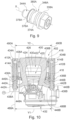
FIG. 8 is a section view of a portion of a vehicle disc brake assembly having a bushing in accordance with a third embodiment of the present invention. -
FIG. 9 is a perspective view of the bushing ofFIG. 8 . -
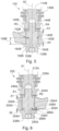
FIG. 10 is a section view of a vehicle disc brake assembly having a bushing in accordance with a fourth embodiment of the present invention. -
FIG. 11 is an enlarged portion ofFIG. 10 . - Referring now to the drawings, there is illustrated in
FIGS. 1 and2 , a portion of a vehicle disc brake assembly, indicated generally at 100. The general structure and operation of thebrake assembly 100 is conventional in the art. Thus, only those portions of thebrake assembly 100 which are necessary for a full understanding of this invention will be explained and illustrated in detail. Also, although this invention will be described and illustrated in connection with the particular vehicle disc brake assembly disclosed herein, it will be appreciated that this invention may be used in connection with other vehicle disc brake assemblies, if so desired. For example, this invention may be used in connection with the disc brake assembly disclosed inU.S. Patent Publication No. 2014/0231191 to Morais et al. . - The
brake assembly 100 is a rod guided or rod sliding type of disc brake assembly and includes a generally C-shaped caliper, indicated generally at 102. Thecaliper 102 includes aninboard leg portion 104 and anoutboard leg portion 106 which are interconnected by first and secondintermediate bridge portions caliper 102 is secured to first andsecond guide rods anchor bracket 112 is, in turn, secured to a stationary component (not shown) of the vehicle by suitable fasteners. For example, the stationary component can be a steering knuckle when thebrake assembly 100 is installed for use on the front of the vehicle or an axle flange or drum-in-hat adapter when thebrake assembly 100 is installed for use on the rear of the vehicle. - In the illustrated embodiment, the
anchor bracket 112 includes first and second axially and outwardly extendingarms second arms inner tie bar 116 and are interconnected at their outboard ends by anouter tie bar 118. Mounted on theanchor bracket 112 are an inboard brake shoe assembly, indicated generally at 120, and an outboard brake shoe assembly, indicated generally at 122. Theinboard brake shoe 120 includes aninboard backing plate 124 and aninboard friction pad 126. Similarly, theoutboard brake shoe 122 includes anoutboard backing plate 128 and anoutboard friction pad 130. - An actuation means is provided for effecting operation of the
brake assembly 100. As illustrated, thebrake assembly 100 has a brake piston (not shown) disposed in a counterbore or recess formed in theinboard leg 104 of thecaliper 102. The actuation means may be a suitable type known to those skilled in the art. As illustrated, the brake piston may be actuated by hydraulic pressure between a non-braking position and a braking position. The brake piston may subsequently be supported in the braking position by an electromechanical actuator, indicated generally at 132. Alternatively, the actuation means may be of a hydraulic, electrical, pneumatic, or mechanical type, or a combination thereof. When thebrake assembly 100 is actuated, for example by a driver or a vehicle controller, a brake loading is developed on thebrake assembly 100. - The
first rod 110A is disposed in a corresponding firstnon-threaded bore 134A provided in thefirst arm 114A and thesecond rod 110B is disposed in a corresponding secondnon-threaded bore 134B provided in thesecond arm 114B. First and second boot seals 136A and 136B, respectively, may be provided between thecaliper 102 and the first andsecond rods fasteners second rods caliper 102. The first andsecond rods caliper 102 to theanchor bracket 112. - The
first fastener 138A extends through a first bore or throughopening 140A provided in afirst lug 142A of thecaliper 102. Thefirst fastener 138A extends along a first axis X1 and is secured tightly - i.e., without slack or play - to thefirst rod 110A. For example, a threadedportion 144A of thefirst fastener 138A may be screwed into a corresponding internally threadedbore 146A provided inside thefirst rod 110A. An annular first fastener bushing, indicated generally at 148A, is secured between thefirst fastener 138A andfirst lug 142A. - Similarly, the
second fastener 138B extends through a second bore or through opening provided in asecond lug 142B of thecaliper 102 along a second axis X2. Thesecond fastener 138B is secured tightly - i.e., without play - to thesecond rod 110B. For example, an externally threadedportion 144B of thesecond fastener 138B may be screwed into a corresponding internally threadedbore 146B provided inside thesecond rod 110B. An annular second fastener bushing, indicated generally at 148B, is secured between thesecond fastener 138B andsecond lug 142B. - Referring now to
FIGS. 3-5 , there is illustrated in detail the first andsecond fasteners second bushings first bushing 148A, as well as portions of thebrake assembly 100 associated with or interacting with thefirst bushing 148A, also corresponds to thesecond bushing 148B and portions of thebrake assembly 100 associated with or interacting with thesecond bushing 148B. Thefirst fastener 138A is generally symmetric about the first axis X1. - The
first bushing 148A is a torus having a substantially circular cross section, similar to an O-ring, and is fabricated from an elastic material such as rubber. Alternatively, thefirst bushing 148A may have other than a circular cross section. For example, thefirst bushing 148A may have a rectilinear cross section. Alternatively, thefirst bushing 148A may be fabricated from other materials. For example, thefirst bushing 148A may be fabricated from plastic material such as nylon. Thefirst bushing 148A has an inner circumference surface, indicated generally at 150A, and an outer circumference surface, indicated generally at 152A. - As discussed, the
first guide rod 110A is secured against thefirst fastener 138A along the first axis X1. Thefirst bushing 148A establishes first and second axial clearances or air gaps A1 and A2, respectively, and a radial clearance or air gap R1. Anouter surface 154A of thefirst fastener 138A has an annular groove 156A circumferentially around the first axis X1 and at an axial midpoint, indicated generally at 158A, of thefirst fastener 138A. As illustrated, the groove 156A is perpendicular to the first axis X1, but the groove 156A may be other than perpendicular to the first axis X1 For example, the groove 156A may be angled relative to the first axis X1 - A cross section of the groove 156A generally corresponds with the cross section of the
first bushing 148A such that thefirst bushing 148A may be positioned in the groove 156A. For example, as illustrated, the circular cross section of thefirst bushing 148A fits within a rectilinear cross section of the groove 156A. Additionally, thefirst bushing 148A may have a larger cross section than the groove 156A and be restrained in the groove 156A by an interference fit. Alternatively, thefirst bushing 148A may be restrained in the groove 156A by inward radial compression towards the first axis X1 or other suitable means. Thefirst bushing 148A is also in contact with aninner surface 164A of thefirst bore 140A such that a friction force is generated to damp axial movement of thefirst fastener 138A in thefirst bore 140A. - The first and second axial clearances Al and A2, respectively, are parallel to the first axis X1 The first axial clearance Al is between the
first guide rod 110A and thefirst lug 142A and the second axial clearance A2 is between the first fastener A2 and thefirst lug 142A. The first and second axial clearances A1 and A2, respectively, may increase and decrease from what is shown inFIG. 4 as thefirst guide rod 110A andfirst fastener 138A move together along the first axis X1 relative to thefirst lug 142A within the first and second axial clearances A1 and A2. Similarly, thesecond bushing 148B establishes third and fourth axial clearances A3 and A4, respectively. - The radial clearance R1 is perpendicular to the first axis X1 and established by the
outer surface 152A having a greater diameter than thefirst fastener 138A. Thefirst bushing 148A remains in contact with thefirst lug 142A for a full circumference of thefirst bushing 148A - i.e., theouter surface 152A contacts theinner surface 164A for 360°. The radial clearance R1 is between thefirst fastener 138A and thefirst lug 142A. As one skilled in the art will recognize, the radial clearance R1 extends circumferentially around thefirst fastener 138A such that a second radial clearance R2 is equal to the radial clearance R1 when thefirst bore 140A andfirst bushing 148A are concentric. Similarly, thesecond bushing 148B establishes third and fourth radial clearances R3 and R4, respectively. - Referring now to
FIGS. 6 and7 , there is illustrated a portion of a vehicledisc brake assembly 200. Because thebrake assembly 200 is a variation of thebrake assembly 100 ofFIGS. 1-5 , like reference numerals, increased by 100, designate corresponding parts in the drawings and detailed description thereof will be omitted. - A
first fastener bushing 248A is located between an axial endpoint, indicated generally at 266A, of afirst lug 242A and an axial endpoint, indicated generally at 268A, of a firstguide rod fastener 238A. - Referring now to
FIGS. 8 and9 , there is illustrated a portion of a vehicledisc brake assembly 300. Because thebrake assembly 300 is a variation of thebrake assembly 100 ofFIGS. 1-5 , like reference numerals, increased by 200, designate corresponding parts in the drawings and detailed description thereof will be omitted. - A
first fastener bushing 348A has asleeve portion 370A, afirst flange 372A, afirst band 374A, asecond band 376A, and asecond flange 378A. As illustrated, thefirst flange 372A,first band 374A,second band 376A, andsecond flange 378A are formed integrally or monolithically with thesleeve portion 370A. Although thefirst bushing 348A is illustrated with the first andsecond bands first bushing 348A may also be formed with more or less than two bands. - The
sleeve 370A is a tube through which a first axis X1 passes and afirst fastener 338A extends. Thefirst flange 372A is on anexterior surface 380A of thesleeve 370A. Thefirst flange 372A is at a first end, indicated generally at 382A, of thesleeve 370A and extends circumferentially around the first axis X1, and rests against afastener flange 384A. - The first and
second bands exterior surface 380A. The first andsecond bands second bands second bands inner surface 364A of afirst bore 340A. - The
second flange 378A is at a second end, indicated generally at 386A, of thesleeve 370A and extends circumferentially around the first axis X1 Thesecond end 386A is opposite the first end 282A and the first andsecond bands second flanges first bushing 348A establishes first and second axial clearances or air gaps A1 and A2, respectively, and first and second radial clearances or air gaps R1 and R2, respectively. The first and second radial clearances R1 and R2, respectively, are between theinner surface 364A and thesleeve 370A. - Referring now to
FIGS. 10 and11 , there is illustrated a vehicledisc brake assembly 400. Because thebrake assembly 400 is a variation of thebrake assembly 100 ofFIGS. 1-5 , like reference numerals, increased by 300, designate corresponding parts in the drawings and detailed description thereof will be omitted. Although illustrated using bushings similar to the first andsecond bushings disc brake assembly 400 may also use bushings similar to those illustrated inFIGS. 6-9 or other suitable bushings. - First and
second guide rods axial centerline 488A of thefirst guide rod 410A and a secondaxial centerline 488B of thesecond guide rod 410B. First and second anchor bracket bores 434A and 434B, respectively, are spaced apart by a second distance Y2 between a thirdaxial centerline 490A of the first anchor bracket bore 434A and a fourthaxial centerline 490B of the second anchor bracket bore 434B. The first and second distances Y1 and Y2, respectively, are generally parallel. - As illustrated, the first distance Y1 is less than the second distance Y2 such that, when the first and
second guide rods second bores second guide rods second guide rods second bores first bore 440A andfirst bushing 448A are not concentric and first and second radial clearances R1 and R2, respectively, are not equal. Similarly, for asecond bushing 448B, there is no longer a constant radial clearance around aguide rod fastener 438B. - The first and second radial clearances R1 and R2, respectively, not being equal develops a preload between the first and
second guide rods second guide rods second guide rods - In accordance with the provisions of the patent statutes, the principle and mode of operation of this invention have been described and illustrated in its preferred embodiments. However, it must be understood that this invention may be practiced otherwise than applying solely the explained and described preferred embodiments without departing from its scope as defined in the appended claims.
Claims (7)
- A vehicle disc brake assembly (100, 200, 300, 400) comprising:a brake caliper (102, 202, 303, 404) having a lug (142A, 242A, 342A, 442A);a bore (140A, 240A, 340A, 440A) through the lug (142A, 242A, 342A, 442A), wherein the bore (140A, 240A, 340A, 440A) has an axis (X1);a guide rod fastener (138A, 238A, 338A, 438A) extending through the bore (140A, 240A, 340A, 440A) and secured to a guide rod (110A, 210A, 310A, 410A);an elastic bushing (148A, 248A, 348A, 448A) between an inner surface (164A, 264A, 364A, 464A) of the bore (140A, 240A, 340A, 440A) and the guide rod fastener (138A, 238A, 338A, 438A), wherein a circumference of the bushing (152A, 252A, 352A, 452A) contacts the inner surface (164A, 264A, 364A, 464A); anda radial clearance (R1, R2) between the inner surface (164A, 264A, 364A, 464A) and the guide rod fastener (138A, 238A, 338A, 438A),wherein the radial clearance (R1, R2) is perpendicular to the axis (X1);a second bore (140B, 240B, 340B, 440B) through a second lug of the brake caliper (102, 202, 303, 404), wherein the second bore (140B, 240B, 340B, 440B) has a second axis (X2);a second guide rod fastener (138B, 238B, 338B, 438B) extending through the second bore (140B, 240B, 340B, 440B) and secured to a second guide rod (110B, 210B, 310B, 410B);a second elastic bushing (148B, 248B, 348B, 448B) between a second inner surface (164B, 264B, 364B, 464B) of the second bore (140B, 240B, 340B, 440B) and the second guide rod fastener (138B, 238B, 338B, 438B), wherein a second circumference (152B, 252B, 352B, 452B) of the second bushing (148B, 248B, 348B, 448B) contacts the second inner surface (164B, 264B, 364B, 464B); anda second radial clearance (R3, R4) between the second inner surface (164B, 264B, 364B, 464B) and the second guide rod fastener (138B, 238B, 338B, 438B), wherein the second radial clearance (R3, R4) is perpendicular to the second axis (X2),wherein the bushing is a first bushing;an anchor bracket (112, 212, 312, 412) having third and fourth bores (134A, 234A, 334A, 434A, 134B, 234B, 334B, 434B), wherein the guide rod (110A, 210A, 310A, 410A) is a first guide rod slidably supported in the third bore (134A, 234A, 334A, 434A) and the second guide rod (110B, 210B, 310B, 410B) is slidably supported in the fourth bore (134A, 234A, 334A, 434A);wherein a first distance (Y1) between axial centerlines of the first and second guide rods (110A, 210A, 310A, 410A, 110B, 210B, 310B, 410B); anda second distance (Y2) between axial centerlines of the third and fourth bores (134A, 234A, 334A, 434A, 134B, 234B, 334B, 434B),characterized in that the first distance (Y1) is less than the second distance (Y2), and the first and second bushings (148A, 248A, 348A, 448A, 148B, 248B, 348B, 448B) are compressed.
- The vehicle disc brake assembly (100, 200, 300, 400) of Claim 1 further comprising:a groove (156A, 256A, 356A, 456A) in a surface of the guide rod fastener (138A, 238A, 338A, 438A), wherein the groove (156A, 256A, 356A, 456A) is circumferential around the axis (X1) and the bushing (148A, 248A, 348A, 448A) is in the groove (156A, 256A, 356A, 456A) and/ora groove (156B, 256B, 356B, 456B) in a surface of the second guide rod fastener (138B, 238B, 338B, 438B), wherein the groove (156B, 256B, 356B, 456B) is circumferential around the second axis (X2) and the second bushing (148B, 248B, 348B, 448B) is in the groove (156B, 256B, 356B, 456B).
- The vehicle disc brake assembly (100, 200, 300, 400) of Claim 2 wherein the groove (156A, 256A, 356A, 456A) of the guide rod fastener (138A, 238A, 338A, 438A) is at an axial midpoint of the guide rod fastener and/or the groove (156B, 256B, 356B, 456B) of the second guide rod fastener (138B, 238B, 338B, 438B) is at an axial midpoint of the second guide rod fastener (138B, 238B, 338B, 438B).
- The vehicle disc brake assembly (100, 200, 300, 400) of Claim 2 wherein the groove (156A, 256A, 356A, 456A) of the guide rod fastener (138A, 238A, 338A, 438A) is at an axial endpoint of the guide rod fastener (138A, 238A, 338A, 438A) and/or of the second guide rod fastener (138B, 238B, 338B, 438B) is at an axial endpoint of the second guide rod fastener (138B, 238B, 338B, 438B).
- A vehicle disc brake assembly (300) comprising:a brake caliper (303) having a lug (342A);a bore (340A) through the lug (342A), wherein the bore (340A) has an axis (X1); a guide rod fastener (338A) extending through the bore (340A) and secured to a guide rod (310A);an elastic bushing (348A) between an inner surface (364A) of the bore (340A) and the guide rod fastener (338A), wherein the bushing (348A) has a sleeve portion (370) with an opening through which the axis (X1) passes and the guide rod fastener (338A) extends;at least one band (374A, 376A) on an exterior surface (380A) of the sleeve portion (370A), wherein a circumference of the at least one band (374A, 376A) contacts the inner surface (364A); anda radial clearance (R1, R2) between the inner surface (364A) and the sleeve portion (370A), whereinthe radial clearance (R1, R2) is perpendicular to the axis (X1);a second bore (340B) through a second lug (342B) of the brake caliper (303), wherein the second bore (340B) has a second axis (X2);a second guide rod fastener (338B) extending through the second bore (340B) and secured to a second guide rod (310B);a second elastic bushing (348B) between a second inner surface (364B) of the second bore (340B) and the second guide rod fastener (338B), wherein the second bushing (348B) has a second sleeve portion (370A) having a second opening through which the second axis (X2) passes and the second guide rod fastener (338B) extends;at least one second band (374A, 376A) on a second exterior surface (380A) of the second sleeve portion (370A), wherein a second circumference of the at least one second band (374A, 376A) contacts the second inner surface (364B); anda second radial clearance (R3, R4) between the second inner surface (364B) and the second sleeve portion (370A), wherein the second radial clearance (R3, R4) is perpendicular to the second axis (X2);wherein the bushing is a first bushing,an anchor bracket (312) having third and fourth bores (334A, 334B), wherein the guide rod (310A) is a first guide rod slidably supported in the third bore (334A) and the second guide rod (310B) is slidably supported in the fourth bore (334B);wherein a first distance (Y1) between axial centerlines of the first and second guide rods (310A, 310B); anda second distance (Y2) between axial centerlines of the third and fourth bores (334A, 334B),characterized in that the first distance (Y1) is less than the second distance (Y2), and the first and second bushings (348A, 348B) are compressed.
- The vehicle disc brake assembly (300) of Claim 5 further comprising:a first flange (372A) at a first end (382A) of the sleeve (370A); anda second flange (378A) at a second end (386A) of the sleeve (370A), wherein the second end of the sleeve is opposite the first end and wherein the at least one band (374A, 376A) is between the first and second flanges (372A, 378A); and/ora first flange (372A) at a first end (382A) of the second sleeve (370A); anda second flange (378A) at a second end (386A) of the second sleeve (370A), wherein the second end of the second sleeve is opposite the first end and wherein the at least one band (374A, 376A) is between the first and second flanges (372A, 378B).
- The vehicle disc brake assembly (300) of Claim 6 wherein the at least one band (374A, 376A)
comprises:a first band (374A, 376A) having a first circumference; anda second band (374A, 376A) having a second circumference, wherein the first and second circumferences contact the inner surface (364A, 364B).
Applications Claiming Priority (2)
| Application Number | Priority Date | Filing Date | Title |
|---|---|---|---|
| US15/278,261 US9976609B2 (en) | 2016-09-28 | 2016-09-28 | Bushing for brake caliper guide rod fasteners |
| PCT/US2017/053375 WO2018064014A2 (en) | 2016-09-28 | 2017-09-26 | Bushing for brake caliper guide rod fasteners |
Publications (3)
| Publication Number | Publication Date |
|---|---|
| EP3519715A2 EP3519715A2 (en) | 2019-08-07 |
| EP3519715A4 EP3519715A4 (en) | 2020-06-03 |
| EP3519715B1 true EP3519715B1 (en) | 2025-05-14 |
Family
ID=61688354
Family Applications (1)
| Application Number | Title | Priority Date | Filing Date |
|---|---|---|---|
| EP17857267.3A Active EP3519715B1 (en) | 2016-09-28 | 2017-09-26 | A vehicle disc brake assembly comprising elastic bushings |
Country Status (4)
| Country | Link |
|---|---|
| US (2) | US9976609B2 (en) |
| EP (1) | EP3519715B1 (en) |
| CN (1) | CN109790888B (en) |
| WO (1) | WO2018064014A2 (en) |
Families Citing this family (8)
| Publication number | Priority date | Publication date | Assignee | Title |
|---|---|---|---|---|
| US9976609B2 (en) * | 2016-09-28 | 2018-05-22 | Kelsey-Hayes Company | Bushing for brake caliper guide rod fasteners |
| US20200182320A1 (en) | 2018-12-07 | 2020-06-11 | ZF Active Safety US Inc. | Brake piston having a non-circular end face for a disc brake assembly with an electric parking brake |
| CN110131340B (en) * | 2019-05-17 | 2020-04-03 | 杨福旺 | Disc type braking device suitable for new energy automobile |
| US11433865B2 (en) | 2019-07-01 | 2022-09-06 | ZF Active Safety US Inc. | Electric parking brake having a gearing with a torque limiting device |
| US11149810B2 (en) | 2019-08-21 | 2021-10-19 | ZF Active Safety US Inc. | Vehicle disc brake assembly having a brake pad with a shim mechanically restrained from lateral movement |
| US11773928B2 (en) * | 2020-12-14 | 2023-10-03 | Arvinmeritor Technology, Llc | Brake assembly having a guide pin assembly |
| KR20250012231A (en) * | 2023-07-17 | 2025-01-24 | 에이치엘만도 주식회사 | Caliper brake |
| IT202300028197A1 (en) * | 2023-12-28 | 2025-06-28 | Brembo Spa | PAD HOLDER PIN AND SLIDE GUIDE ASSEMBLY, FLOATING BRAKE CALIPER |
Family Cites Families (33)
| Publication number | Priority date | Publication date | Assignee | Title |
|---|---|---|---|---|
| US3343632A (en) * | 1965-07-12 | 1967-09-26 | Lambert & Brake Corp | Self-adjusting disc brake |
| US3897858A (en) * | 1971-10-20 | 1975-08-05 | Nissan Motor | Closed loop type disc brake |
| GB1420859A (en) * | 1972-09-19 | 1976-01-14 | Akebono Brake Ind | Disc brakes |
| US3917032A (en) * | 1974-02-11 | 1975-11-04 | Gen Motors Corp | Single mount and guide pin for a caliper of a disc brake assembly |
| GB1500907A (en) | 1974-03-09 | 1978-02-15 | Girling Ltd | Disc brakes |
| GB1506709A (en) * | 1974-04-02 | 1978-04-12 | Girling Ltd | Vehicle brakes |
| US4261443A (en) * | 1974-11-05 | 1981-04-14 | Girling Limited | Disc brakes for vehicles |
| DE2804977C2 (en) * | 1978-02-06 | 1986-07-10 | Alfred Teves Gmbh, 6000 Frankfurt | Floating caliper brakes, in particular for motor vehicles |
| JPS5712130A (en) * | 1980-06-26 | 1982-01-22 | Aisin Seiki Co Ltd | Pin-slide type disc brake |
| DE9305631U1 (en) * | 1993-04-15 | 1994-08-25 | Lucas Industries P.L.C., Solihull, West Midlands | Floating caliper brake, in particular floating caliper partial lining disc brake |
| JPH08169207A (en) * | 1994-08-18 | 1996-07-02 | Bridgestone Metalpha Kk | Pneumatic radial tire |
| US5813590A (en) * | 1995-12-18 | 1998-09-29 | Micron Technology, Inc. | Extended travel wire bonding machine |
| JP3348767B2 (en) * | 1997-08-22 | 2002-11-20 | トヨタ自動車株式会社 | Disc brake device |
| US6260832B1 (en) * | 1997-12-17 | 2001-07-17 | Marzocchi S.P.A. | Shock absorber with adjustable compression and rebound |
| JPH11287263A (en) * | 1998-03-31 | 1999-10-19 | Tokico Ltd | Disc brake |
| US6397986B2 (en) * | 1999-09-23 | 2002-06-04 | Westinghouse Air Brake Technologies Corporation | Collet style tread brake unit |
| JP2002039233A (en) * | 2000-07-21 | 2002-02-06 | Aisin Seiki Co Ltd | Disc brake |
| US6533079B2 (en) * | 2001-07-19 | 2003-03-18 | Robert Bosch Corporation | Disc brake |
| US6609594B1 (en) | 2001-10-11 | 2003-08-26 | Robert Bosch Corporation | Disc brake |
| DE10312479B4 (en) * | 2003-03-20 | 2007-05-03 | Lucas Automotive Gmbh | disc brake |
| JP2005220942A (en) | 2004-02-03 | 2005-08-18 | Advics:Kk | Pin slide type disk brake |
| JP4465524B2 (en) * | 2004-08-30 | 2010-05-19 | Smc株式会社 | Electric actuator |
| CN2760328Y (en) * | 2004-12-13 | 2006-02-22 | 杨位本 | Clamping disk type brake |
| US7356901B1 (en) * | 2005-12-20 | 2008-04-15 | Robert Bosch Gmbh | Method of forming bushings between guide pins and guide pin bores |
| JP4513739B2 (en) | 2005-12-27 | 2010-07-28 | ブラザー工業株式会社 | Inkjet printer |
| US7721854B1 (en) | 2007-03-30 | 2010-05-25 | Robert Bosch Gmbh | Assured running clearance caliper |
| US7955228B2 (en) * | 2008-09-08 | 2011-06-07 | Hamilton Brian H | Bicycle trainer with variable magnetic resistance to pedaling |
| US20120067678A1 (en) * | 2010-09-21 | 2012-03-22 | Kelsey-Hayes Company | Anchor bracket for use in a disc brake assembly and method for making the same |
| JP2012107740A (en) * | 2010-10-28 | 2012-06-07 | Advics Co Ltd | Pin slide type floating disc brake |
| JP6081166B2 (en) * | 2012-11-28 | 2017-02-15 | Ntn株式会社 | Disc brake device |
| US9353810B2 (en) | 2013-02-21 | 2016-05-31 | Kelsey-Hayes Company | Disc brake assembly with non-rotatable vehicle component and method for producing same |
| US9551387B2 (en) * | 2015-02-06 | 2017-01-24 | Kelsey-Hayes Company | Disc brake assembly with guide pin locating feature |
| US9976609B2 (en) * | 2016-09-28 | 2018-05-22 | Kelsey-Hayes Company | Bushing for brake caliper guide rod fasteners |
-
2016
- 2016-09-28 US US15/278,261 patent/US9976609B2/en active Active
-
2017
- 2017-09-26 WO PCT/US2017/053375 patent/WO2018064014A2/en not_active Ceased
- 2017-09-26 EP EP17857267.3A patent/EP3519715B1/en active Active
- 2017-09-26 CN CN201780059895.8A patent/CN109790888B/en active Active
-
2018
- 2018-04-25 US US15/961,956 patent/US10458494B2/en active Active
Also Published As
| Publication number | Publication date |
|---|---|
| US20180087589A1 (en) | 2018-03-29 |
| WO2018064014A2 (en) | 2018-04-05 |
| US10458494B2 (en) | 2019-10-29 |
| US20180238406A1 (en) | 2018-08-23 |
| CN109790888B (en) | 2020-12-15 |
| US9976609B2 (en) | 2018-05-22 |
| EP3519715A2 (en) | 2019-08-07 |
| EP3519715A4 (en) | 2020-06-03 |
| CN109790888A (en) | 2019-05-21 |
| WO2018064014A3 (en) | 2018-07-26 |
Similar Documents
| Publication | Publication Date | Title |
|---|---|---|
| CN109790888B (en) | Bushings for brake caliper guide rod fasteners | |
| EP2619474B1 (en) | Anchor bracket for use in a disc brake assembly and method for making the same | |
| US9016442B2 (en) | Disc brake apparatus | |
| US9353810B2 (en) | Disc brake assembly with non-rotatable vehicle component and method for producing same | |
| US10054175B2 (en) | Controlled contact guide pin for vehicle disc brakes | |
| US8905201B2 (en) | Vehicle disc brake | |
| US20140116817A1 (en) | Guide Pin For Disc Brake Assembly And Disc Brake Assembly Including Such A Guide Pin | |
| US20050284710A1 (en) | Brake assembly | |
| US9062726B2 (en) | Disc brake device and caliper | |
| US11698115B2 (en) | Sliding mechanism for guide pins of a disc brake assembly | |
| US9394954B2 (en) | Guide pin for disc brake assembly and disc brake assembly including such a guide pin | |
| US9850967B2 (en) | Brake caliper guide pin low pressure isolation damper | |
| US20060289253A1 (en) | Monoblock caliper housing for a disc brake assembly | |
| US20220299074A1 (en) | Brake assembly | |
| US5979611A (en) | Disc brake device | |
| US3495689A (en) | Disc brake caliper mounting structure | |
| US20220299073A1 (en) | Disc brake | |
| US20090145702A1 (en) | Brake pad for a vehicle disc brake assembly | |
| US11879511B2 (en) | Brake assembly | |
| US20050109569A1 (en) | Piston for disc brake assembly | |
| JP2006193148A (en) | Corner assembly for vehicle | |
| US3301355A (en) | Borgard brake support assembly | |
| JP2026064219A (en) | Brake assembly with guide pin assembly | |
| JP2546371Y2 (en) | Dust boots for disc brakes |
Legal Events
| Date | Code | Title | Description |
|---|---|---|---|
| STAA | Information on the status of an ep patent application or granted ep patent |
Free format text: STATUS: THE INTERNATIONAL PUBLICATION HAS BEEN MADE |
|
| PUAI | Public reference made under article 153(3) epc to a published international application that has entered the european phase |
Free format text: ORIGINAL CODE: 0009012 |
|
| STAA | Information on the status of an ep patent application or granted ep patent |
Free format text: STATUS: REQUEST FOR EXAMINATION WAS MADE |
|
| 17P | Request for examination filed |
Effective date: 20190312 |
|
| AK | Designated contracting states |
Kind code of ref document: A2 Designated state(s): AL AT BE BG CH CY CZ DE DK EE ES FI FR GB GR HR HU IE IS IT LI LT LU LV MC MK MT NL NO PL PT RO RS SE SI SK SM TR |
|
| AX | Request for extension of the european patent |
Extension state: BA ME |
|
| DAV | Request for validation of the european patent (deleted) | ||
| DAX | Request for extension of the european patent (deleted) | ||
| RAP1 | Party data changed (applicant data changed or rights of an application transferred) |
Owner name: LUCAS AUTOMOTIVE GMBH Owner name: ZF ACTIVE SAFETY US INC. |
|
| RAP1 | Party data changed (applicant data changed or rights of an application transferred) |
Owner name: ZF ACTIVE SAFETY US INC. Owner name: ZF ACTIVE SAFETY GMBH |
|
| A4 | Supplementary search report drawn up and despatched |
Effective date: 20200506 |
|
| RIC1 | Information provided on ipc code assigned before grant |
Ipc: F16D 55/227 20060101ALN20200428BHEP Ipc: F16D 55/2265 20060101AFI20200428BHEP Ipc: F16D 65/00 20060101ALI20200428BHEP |
|
| STAA | Information on the status of an ep patent application or granted ep patent |
Free format text: STATUS: EXAMINATION IS IN PROGRESS |
|
| 17Q | First examination report despatched |
Effective date: 20220704 |
|
| RIC1 | Information provided on ipc code assigned before grant |
Ipc: F16D 55/227 20060101ALN20241016BHEP Ipc: F16D 65/00 20060101ALI20241016BHEP Ipc: F16D 55/2265 20060101AFI20241016BHEP |
|
| GRAP | Despatch of communication of intention to grant a patent |
Free format text: ORIGINAL CODE: EPIDOSNIGR1 |
|
| STAA | Information on the status of an ep patent application or granted ep patent |
Free format text: STATUS: GRANT OF PATENT IS INTENDED |
|
| INTG | Intention to grant announced |
Effective date: 20241211 |
|
| GRAS | Grant fee paid |
Free format text: ORIGINAL CODE: EPIDOSNIGR3 |
|
| GRAA | (expected) grant |
Free format text: ORIGINAL CODE: 0009210 |
|
| STAA | Information on the status of an ep patent application or granted ep patent |
Free format text: STATUS: THE PATENT HAS BEEN GRANTED |
|
| AK | Designated contracting states |
Kind code of ref document: B1 Designated state(s): AL AT BE BG CH CY CZ DE DK EE ES FI FR GB GR HR HU IE IS IT LI LT LU LV MC MK MT NL NO PL PT RO RS SE SI SK SM TR |
|
| REG | Reference to a national code |
Ref country code: GB Ref legal event code: FG4D |
|
| REG | Reference to a national code |
Ref country code: CH Ref legal event code: EP |
|
| REG | Reference to a national code |
Ref country code: DE Ref legal event code: R096 Ref document number: 602017089488 Country of ref document: DE |
|
| REG | Reference to a national code |
Ref country code: IE Ref legal event code: FG4D |
|
| REG | Reference to a national code |
Ref country code: NL Ref legal event code: MP Effective date: 20250514 |
|
| PG25 | Lapsed in a contracting state [announced via postgrant information from national office to epo] |
Ref country code: PT Free format text: LAPSE BECAUSE OF FAILURE TO SUBMIT A TRANSLATION OF THE DESCRIPTION OR TO PAY THE FEE WITHIN THE PRESCRIBED TIME-LIMIT Effective date: 20250915 Ref country code: ES Free format text: LAPSE BECAUSE OF FAILURE TO SUBMIT A TRANSLATION OF THE DESCRIPTION OR TO PAY THE FEE WITHIN THE PRESCRIBED TIME-LIMIT Effective date: 20250514 Ref country code: FI Free format text: LAPSE BECAUSE OF FAILURE TO SUBMIT A TRANSLATION OF THE DESCRIPTION OR TO PAY THE FEE WITHIN THE PRESCRIBED TIME-LIMIT Effective date: 20250514 |
|
| PGFP | Annual fee paid to national office [announced via postgrant information from national office to epo] |
Ref country code: DE Payment date: 20250702 Year of fee payment: 9 |
|
| REG | Reference to a national code |
Ref country code: LT Ref legal event code: MG9D |
|
| PG25 | Lapsed in a contracting state [announced via postgrant information from national office to epo] |
Ref country code: NO Free format text: LAPSE BECAUSE OF FAILURE TO SUBMIT A TRANSLATION OF THE DESCRIPTION OR TO PAY THE FEE WITHIN THE PRESCRIBED TIME-LIMIT Effective date: 20250814 Ref country code: GR Free format text: LAPSE BECAUSE OF FAILURE TO SUBMIT A TRANSLATION OF THE DESCRIPTION OR TO PAY THE FEE WITHIN THE PRESCRIBED TIME-LIMIT Effective date: 20250815 |
|
| PG25 | Lapsed in a contracting state [announced via postgrant information from national office to epo] |
Ref country code: NL Free format text: LAPSE BECAUSE OF FAILURE TO SUBMIT A TRANSLATION OF THE DESCRIPTION OR TO PAY THE FEE WITHIN THE PRESCRIBED TIME-LIMIT Effective date: 20250514 Ref country code: PL Free format text: LAPSE BECAUSE OF FAILURE TO SUBMIT A TRANSLATION OF THE DESCRIPTION OR TO PAY THE FEE WITHIN THE PRESCRIBED TIME-LIMIT Effective date: 20250514 |
|
| REG | Reference to a national code |
Ref country code: AT Ref legal event code: MK05 Ref document number: 1794996 Country of ref document: AT Kind code of ref document: T Effective date: 20250514 |
|
| PG25 | Lapsed in a contracting state [announced via postgrant information from national office to epo] |
Ref country code: BG Free format text: LAPSE BECAUSE OF FAILURE TO SUBMIT A TRANSLATION OF THE DESCRIPTION OR TO PAY THE FEE WITHIN THE PRESCRIBED TIME-LIMIT Effective date: 20250514 |
|
| PG25 | Lapsed in a contracting state [announced via postgrant information from national office to epo] |
Ref country code: HR Free format text: LAPSE BECAUSE OF FAILURE TO SUBMIT A TRANSLATION OF THE DESCRIPTION OR TO PAY THE FEE WITHIN THE PRESCRIBED TIME-LIMIT Effective date: 20250514 |
|
| PG25 | Lapsed in a contracting state [announced via postgrant information from national office to epo] |
Ref country code: AT Free format text: LAPSE BECAUSE OF FAILURE TO SUBMIT A TRANSLATION OF THE DESCRIPTION OR TO PAY THE FEE WITHIN THE PRESCRIBED TIME-LIMIT Effective date: 20250514 |
|
| PG25 | Lapsed in a contracting state [announced via postgrant information from national office to epo] |
Ref country code: RS Free format text: LAPSE BECAUSE OF FAILURE TO SUBMIT A TRANSLATION OF THE DESCRIPTION OR TO PAY THE FEE WITHIN THE PRESCRIBED TIME-LIMIT Effective date: 20250814 |
|
| PG25 | Lapsed in a contracting state [announced via postgrant information from national office to epo] |
Ref country code: IS Free format text: LAPSE BECAUSE OF FAILURE TO SUBMIT A TRANSLATION OF THE DESCRIPTION OR TO PAY THE FEE WITHIN THE PRESCRIBED TIME-LIMIT Effective date: 20250914 |
|
| PG25 | Lapsed in a contracting state [announced via postgrant information from national office to epo] |
Ref country code: LV Free format text: LAPSE BECAUSE OF FAILURE TO SUBMIT A TRANSLATION OF THE DESCRIPTION OR TO PAY THE FEE WITHIN THE PRESCRIBED TIME-LIMIT Effective date: 20250514 |
|
| PG25 | Lapsed in a contracting state [announced via postgrant information from national office to epo] |
Ref country code: DK Free format text: LAPSE BECAUSE OF FAILURE TO SUBMIT A TRANSLATION OF THE DESCRIPTION OR TO PAY THE FEE WITHIN THE PRESCRIBED TIME-LIMIT Effective date: 20250514 Ref country code: SM Free format text: LAPSE BECAUSE OF FAILURE TO SUBMIT A TRANSLATION OF THE DESCRIPTION OR TO PAY THE FEE WITHIN THE PRESCRIBED TIME-LIMIT Effective date: 20250514 |
|
| PG25 | Lapsed in a contracting state [announced via postgrant information from national office to epo] |
Ref country code: CZ Free format text: LAPSE BECAUSE OF FAILURE TO SUBMIT A TRANSLATION OF THE DESCRIPTION OR TO PAY THE FEE WITHIN THE PRESCRIBED TIME-LIMIT Effective date: 20250514 |
|
| PG25 | Lapsed in a contracting state [announced via postgrant information from national office to epo] |
Ref country code: EE Free format text: LAPSE BECAUSE OF FAILURE TO SUBMIT A TRANSLATION OF THE DESCRIPTION OR TO PAY THE FEE WITHIN THE PRESCRIBED TIME-LIMIT Effective date: 20250514 |
|
| PG25 | Lapsed in a contracting state [announced via postgrant information from national office to epo] |
Ref country code: SK Free format text: LAPSE BECAUSE OF FAILURE TO SUBMIT A TRANSLATION OF THE DESCRIPTION OR TO PAY THE FEE WITHIN THE PRESCRIBED TIME-LIMIT Effective date: 20250514 Ref country code: RO Free format text: LAPSE BECAUSE OF FAILURE TO SUBMIT A TRANSLATION OF THE DESCRIPTION OR TO PAY THE FEE WITHIN THE PRESCRIBED TIME-LIMIT Effective date: 20250514 |
|
| PG25 | Lapsed in a contracting state [announced via postgrant information from national office to epo] |
Ref country code: IT Free format text: LAPSE BECAUSE OF FAILURE TO SUBMIT A TRANSLATION OF THE DESCRIPTION OR TO PAY THE FEE WITHIN THE PRESCRIBED TIME-LIMIT Effective date: 20250514 |
|
| REG | Reference to a national code |
Ref country code: DE Ref legal event code: R097 Ref document number: 602017089488 Country of ref document: DE |
|
| PLBE | No opposition filed within time limit |
Free format text: ORIGINAL CODE: 0009261 |
|
| STAA | Information on the status of an ep patent application or granted ep patent |
Free format text: STATUS: NO OPPOSITION FILED WITHIN TIME LIMIT |
|
| REG | Reference to a national code |
Ref country code: CH Ref legal event code: L10 Free format text: ST27 STATUS EVENT CODE: U-0-0-L10-L00 (AS PROVIDED BY THE NATIONAL OFFICE) Effective date: 20260325 |
|
| 26N | No opposition filed |
Effective date: 20260217 |
|
| REG | Reference to a national code |
Ref country code: CH Ref legal event code: H13 Free format text: ST27 STATUS EVENT CODE: U-0-0-H10-H13 (AS PROVIDED BY THE NATIONAL OFFICE) Effective date: 20260504 |