EP3519215B1 - Electric vehicle thermal management system with battery heat storage - Google Patents
Electric vehicle thermal management system with battery heat storage Download PDFInfo
- Publication number
- EP3519215B1 EP3519215B1 EP17857287.1A EP17857287A EP3519215B1 EP 3519215 B1 EP3519215 B1 EP 3519215B1 EP 17857287 A EP17857287 A EP 17857287A EP 3519215 B1 EP3519215 B1 EP 3519215B1
- Authority
- EP
- European Patent Office
- Prior art keywords
- coolant
- powertrain
- voltage battery
- radiator
- high voltage
- Prior art date
- Legal status (The legal status is an assumption and is not a legal conclusion. Google has not performed a legal analysis and makes no representation as to the accuracy of the status listed.)
- Active
Links
Images



















Classifications
-
- H—ELECTRICITY
- H01—ELECTRIC ELEMENTS
- H01M—PROCESSES OR MEANS, e.g. BATTERIES, FOR THE DIRECT CONVERSION OF CHEMICAL ENERGY INTO ELECTRICAL ENERGY
- H01M10/00—Secondary cells; Manufacture thereof
- H01M10/60—Heating or cooling; Temperature control
- H01M10/62—Heating or cooling; Temperature control specially adapted for specific applications
- H01M10/625—Vehicles
-
- B—PERFORMING OPERATIONS; TRANSPORTING
- B60—VEHICLES IN GENERAL
- B60H—ARRANGEMENTS OF HEATING, COOLING, VENTILATING OR OTHER AIR-TREATING DEVICES SPECIALLY ADAPTED FOR PASSENGER OR GOODS SPACES OF VEHICLES
- B60H1/00—Heating, cooling or ventilating devices
- B60H1/00271—HVAC devices specially adapted for particular vehicle parts or components and being connected to the vehicle HVAC unit
- B60H1/00278—HVAC devices specially adapted for particular vehicle parts or components and being connected to the vehicle HVAC unit for the battery
-
- B—PERFORMING OPERATIONS; TRANSPORTING
- B60—VEHICLES IN GENERAL
- B60H—ARRANGEMENTS OF HEATING, COOLING, VENTILATING OR OTHER AIR-TREATING DEVICES SPECIALLY ADAPTED FOR PASSENGER OR GOODS SPACES OF VEHICLES
- B60H1/00—Heating, cooling or ventilating devices
- B60H1/00492—Heating, cooling or ventilating devices comprising regenerative heating or cooling means, e.g. heat accumulators
- B60H1/00499—Heat or cold storage without phase change including solid bodies, e.g. batteries
-
- B—PERFORMING OPERATIONS; TRANSPORTING
- B60—VEHICLES IN GENERAL
- B60H—ARRANGEMENTS OF HEATING, COOLING, VENTILATING OR OTHER AIR-TREATING DEVICES SPECIALLY ADAPTED FOR PASSENGER OR GOODS SPACES OF VEHICLES
- B60H1/00—Heating, cooling or ventilating devices
- B60H1/00642—Control systems or circuits; Control members or indication devices for heating, cooling or ventilating devices
- B60H1/00814—Control systems or circuits characterised by their output, for controlling particular components of the heating, cooling or ventilating installation
- B60H1/00878—Control systems or circuits characterised by their output, for controlling particular components of the heating, cooling or ventilating installation the components being temperature regulating devices
- B60H1/00899—Controlling the flow of liquid in a heat pump system
- B60H1/00921—Controlling the flow of liquid in a heat pump system where the flow direction of the refrigerant does not change and there is an extra subcondenser, e.g. in an air duct
-
- B—PERFORMING OPERATIONS; TRANSPORTING
- B60—VEHICLES IN GENERAL
- B60H—ARRANGEMENTS OF HEATING, COOLING, VENTILATING OR OTHER AIR-TREATING DEVICES SPECIALLY ADAPTED FOR PASSENGER OR GOODS SPACES OF VEHICLES
- B60H1/00—Heating, cooling or ventilating devices
- B60H1/32—Cooling devices
- B60H1/3204—Cooling devices using compression
- B60H1/3228—Cooling devices using compression characterised by refrigerant circuit configurations
- B60H1/32281—Cooling devices using compression characterised by refrigerant circuit configurations comprising a single secondary circuit, e.g. at evaporator or condenser side
-
- B—PERFORMING OPERATIONS; TRANSPORTING
- B60—VEHICLES IN GENERAL
- B60L—PROPULSION OF ELECTRICALLY-PROPELLED VEHICLES; SUPPLYING ELECTRIC POWER FOR AUXILIARY EQUIPMENT OF ELECTRICALLY-PROPELLED VEHICLES; ELECTRODYNAMIC BRAKE SYSTEMS FOR VEHICLES IN GENERAL; MAGNETIC SUSPENSION OR LEVITATION FOR VEHICLES; MONITORING OPERATING VARIABLES OF ELECTRICALLY-PROPELLED VEHICLES; ELECTRIC SAFETY DEVICES FOR ELECTRICALLY-PROPELLED VEHICLES
- B60L50/00—Electric propulsion with power supplied within the vehicle
- B60L50/50—Electric propulsion with power supplied within the vehicle using propulsion power supplied by batteries or fuel cells
- B60L50/60—Electric propulsion with power supplied within the vehicle using propulsion power supplied by batteries or fuel cells using power supplied by batteries
- B60L50/64—Constructional details of batteries specially adapted for electric vehicles
-
- B—PERFORMING OPERATIONS; TRANSPORTING
- B60—VEHICLES IN GENERAL
- B60L—PROPULSION OF ELECTRICALLY-PROPELLED VEHICLES; SUPPLYING ELECTRIC POWER FOR AUXILIARY EQUIPMENT OF ELECTRICALLY-PROPELLED VEHICLES; ELECTRODYNAMIC BRAKE SYSTEMS FOR VEHICLES IN GENERAL; MAGNETIC SUSPENSION OR LEVITATION FOR VEHICLES; MONITORING OPERATING VARIABLES OF ELECTRICALLY-PROPELLED VEHICLES; ELECTRIC SAFETY DEVICES FOR ELECTRICALLY-PROPELLED VEHICLES
- B60L58/00—Methods or circuit arrangements for monitoring or controlling batteries or fuel cells, specially adapted for electric vehicles
- B60L58/10—Methods or circuit arrangements for monitoring or controlling batteries or fuel cells, specially adapted for electric vehicles for monitoring or controlling batteries
- B60L58/24—Methods or circuit arrangements for monitoring or controlling batteries or fuel cells, specially adapted for electric vehicles for monitoring or controlling batteries for controlling the temperature of batteries
- B60L58/26—Methods or circuit arrangements for monitoring or controlling batteries or fuel cells, specially adapted for electric vehicles for monitoring or controlling batteries for controlling the temperature of batteries by cooling
-
- H—ELECTRICITY
- H01—ELECTRIC ELEMENTS
- H01M—PROCESSES OR MEANS, e.g. BATTERIES, FOR THE DIRECT CONVERSION OF CHEMICAL ENERGY INTO ELECTRICAL ENERGY
- H01M10/00—Secondary cells; Manufacture thereof
- H01M10/60—Heating or cooling; Temperature control
- H01M10/61—Types of temperature control
- H01M10/613—Cooling or keeping cold
-
- H—ELECTRICITY
- H01—ELECTRIC ELEMENTS
- H01M—PROCESSES OR MEANS, e.g. BATTERIES, FOR THE DIRECT CONVERSION OF CHEMICAL ENERGY INTO ELECTRICAL ENERGY
- H01M10/00—Secondary cells; Manufacture thereof
- H01M10/60—Heating or cooling; Temperature control
- H01M10/63—Control systems
-
- H—ELECTRICITY
- H01—ELECTRIC ELEMENTS
- H01M—PROCESSES OR MEANS, e.g. BATTERIES, FOR THE DIRECT CONVERSION OF CHEMICAL ENERGY INTO ELECTRICAL ENERGY
- H01M10/00—Secondary cells; Manufacture thereof
- H01M10/60—Heating or cooling; Temperature control
- H01M10/66—Heat-exchange relationships between the cells and other systems, e.g. central heating systems or fuel cells
-
- H—ELECTRICITY
- H01—ELECTRIC ELEMENTS
- H01M—PROCESSES OR MEANS, e.g. BATTERIES, FOR THE DIRECT CONVERSION OF CHEMICAL ENERGY INTO ELECTRICAL ENERGY
- H01M10/00—Secondary cells; Manufacture thereof
- H01M10/60—Heating or cooling; Temperature control
- H01M10/66—Heat-exchange relationships between the cells and other systems, e.g. central heating systems or fuel cells
- H01M10/663—Heat-exchange relationships between the cells and other systems, e.g. central heating systems or fuel cells the system being an air-conditioner or an engine
-
- B—PERFORMING OPERATIONS; TRANSPORTING
- B60—VEHICLES IN GENERAL
- B60H—ARRANGEMENTS OF HEATING, COOLING, VENTILATING OR OTHER AIR-TREATING DEVICES SPECIALLY ADAPTED FOR PASSENGER OR GOODS SPACES OF VEHICLES
- B60H1/00—Heating, cooling or ventilating devices
- B60H1/00357—Air-conditioning arrangements specially adapted for particular vehicles
- B60H1/00385—Air-conditioning arrangements specially adapted for particular vehicles for vehicles having an electrical drive, e.g. hybrid or fuel cell
- B60H1/00392—Air-conditioning arrangements specially adapted for particular vehicles for vehicles having an electrical drive, e.g. hybrid or fuel cell for electric vehicles having only electric drive means
-
- B—PERFORMING OPERATIONS; TRANSPORTING
- B60—VEHICLES IN GENERAL
- B60H—ARRANGEMENTS OF HEATING, COOLING, VENTILATING OR OTHER AIR-TREATING DEVICES SPECIALLY ADAPTED FOR PASSENGER OR GOODS SPACES OF VEHICLES
- B60H1/00—Heating, cooling or ventilating devices
- B60H1/00271—HVAC devices specially adapted for particular vehicle parts or components and being connected to the vehicle HVAC unit
- B60H2001/00307—Component temperature regulation using a liquid flow
-
- B—PERFORMING OPERATIONS; TRANSPORTING
- B60—VEHICLES IN GENERAL
- B60H—ARRANGEMENTS OF HEATING, COOLING, VENTILATING OR OTHER AIR-TREATING DEVICES SPECIALLY ADAPTED FOR PASSENGER OR GOODS SPACES OF VEHICLES
- B60H1/00—Heating, cooling or ventilating devices
- B60H1/00642—Control systems or circuits; Control members or indication devices for heating, cooling or ventilating devices
- B60H1/00814—Control systems or circuits characterised by their output, for controlling particular components of the heating, cooling or ventilating installation
- B60H1/00878—Control systems or circuits characterised by their output, for controlling particular components of the heating, cooling or ventilating installation the components being temperature regulating devices
- B60H2001/00928—Control systems or circuits characterised by their output, for controlling particular components of the heating, cooling or ventilating installation the components being temperature regulating devices comprising a secondary circuit
-
- B—PERFORMING OPERATIONS; TRANSPORTING
- B60—VEHICLES IN GENERAL
- B60H—ARRANGEMENTS OF HEATING, COOLING, VENTILATING OR OTHER AIR-TREATING DEVICES SPECIALLY ADAPTED FOR PASSENGER OR GOODS SPACES OF VEHICLES
- B60H1/00—Heating, cooling or ventilating devices
- B60H1/00642—Control systems or circuits; Control members or indication devices for heating, cooling or ventilating devices
- B60H1/00814—Control systems or circuits characterised by their output, for controlling particular components of the heating, cooling or ventilating installation
- B60H1/00878—Control systems or circuits characterised by their output, for controlling particular components of the heating, cooling or ventilating installation the components being temperature regulating devices
- B60H2001/00942—Control systems or circuits characterised by their output, for controlling particular components of the heating, cooling or ventilating installation the components being temperature regulating devices comprising a plurality of heat exchangers, e.g. for multi zone heating or cooling
-
- B—PERFORMING OPERATIONS; TRANSPORTING
- B60—VEHICLES IN GENERAL
- B60H—ARRANGEMENTS OF HEATING, COOLING, VENTILATING OR OTHER AIR-TREATING DEVICES SPECIALLY ADAPTED FOR PASSENGER OR GOODS SPACES OF VEHICLES
- B60H1/00—Heating, cooling or ventilating devices
- B60H1/00642—Control systems or circuits; Control members or indication devices for heating, cooling or ventilating devices
- B60H1/00814—Control systems or circuits characterised by their output, for controlling particular components of the heating, cooling or ventilating installation
- B60H1/00878—Control systems or circuits characterised by their output, for controlling particular components of the heating, cooling or ventilating installation the components being temperature regulating devices
- B60H2001/00949—Control systems or circuits characterised by their output, for controlling particular components of the heating, cooling or ventilating installation the components being temperature regulating devices comprising additional heating/cooling sources, e.g. second evaporator
-
- B—PERFORMING OPERATIONS; TRANSPORTING
- B60—VEHICLES IN GENERAL
- B60H—ARRANGEMENTS OF HEATING, COOLING, VENTILATING OR OTHER AIR-TREATING DEVICES SPECIALLY ADAPTED FOR PASSENGER OR GOODS SPACES OF VEHICLES
- B60H1/00—Heating, cooling or ventilating devices
- B60H1/00642—Control systems or circuits; Control members or indication devices for heating, cooling or ventilating devices
- B60H1/00814—Control systems or circuits characterised by their output, for controlling particular components of the heating, cooling or ventilating installation
- B60H1/00878—Control systems or circuits characterised by their output, for controlling particular components of the heating, cooling or ventilating installation the components being temperature regulating devices
- B60H2001/00957—Control systems or circuits characterised by their output, for controlling particular components of the heating, cooling or ventilating installation the components being temperature regulating devices comprising locations with heat exchange within the refrigerant circuit itself, e.g. cross-, counter-, or parallel heat exchange
-
- B—PERFORMING OPERATIONS; TRANSPORTING
- B60—VEHICLES IN GENERAL
- B60K—ARRANGEMENT OR MOUNTING OF PROPULSION UNITS OR OF TRANSMISSIONS IN VEHICLES; ARRANGEMENT OR MOUNTING OF PLURAL DIVERSE PRIME-MOVERS IN VEHICLES; AUXILIARY DRIVES FOR VEHICLES; INSTRUMENTATION OR DASHBOARDS FOR VEHICLES; ARRANGEMENTS IN CONNECTION WITH COOLING, AIR INTAKE, GAS EXHAUST OR FUEL SUPPLY OF PROPULSION UNITS IN VEHICLES
- B60K1/00—Arrangement or mounting of electrical propulsion units
- B60K1/04—Arrangement or mounting of electrical propulsion units of the electric storage means for propulsion
-
- B—PERFORMING OPERATIONS; TRANSPORTING
- B60—VEHICLES IN GENERAL
- B60K—ARRANGEMENT OR MOUNTING OF PROPULSION UNITS OR OF TRANSMISSIONS IN VEHICLES; ARRANGEMENT OR MOUNTING OF PLURAL DIVERSE PRIME-MOVERS IN VEHICLES; AUXILIARY DRIVES FOR VEHICLES; INSTRUMENTATION OR DASHBOARDS FOR VEHICLES; ARRANGEMENTS IN CONNECTION WITH COOLING, AIR INTAKE, GAS EXHAUST OR FUEL SUPPLY OF PROPULSION UNITS IN VEHICLES
- B60K11/00—Arrangement in connection with cooling of propulsion units
- B60K11/02—Arrangement in connection with cooling of propulsion units with liquid cooling
-
- B—PERFORMING OPERATIONS; TRANSPORTING
- B60—VEHICLES IN GENERAL
- B60K—ARRANGEMENT OR MOUNTING OF PROPULSION UNITS OR OF TRANSMISSIONS IN VEHICLES; ARRANGEMENT OR MOUNTING OF PLURAL DIVERSE PRIME-MOVERS IN VEHICLES; AUXILIARY DRIVES FOR VEHICLES; INSTRUMENTATION OR DASHBOARDS FOR VEHICLES; ARRANGEMENTS IN CONNECTION WITH COOLING, AIR INTAKE, GAS EXHAUST OR FUEL SUPPLY OF PROPULSION UNITS IN VEHICLES
- B60K1/00—Arrangement or mounting of electrical propulsion units
- B60K2001/003—Arrangement or mounting of electrical propulsion units with means for cooling the electrical propulsion units
-
- B—PERFORMING OPERATIONS; TRANSPORTING
- B60—VEHICLES IN GENERAL
- B60K—ARRANGEMENT OR MOUNTING OF PROPULSION UNITS OR OF TRANSMISSIONS IN VEHICLES; ARRANGEMENT OR MOUNTING OF PLURAL DIVERSE PRIME-MOVERS IN VEHICLES; AUXILIARY DRIVES FOR VEHICLES; INSTRUMENTATION OR DASHBOARDS FOR VEHICLES; ARRANGEMENTS IN CONNECTION WITH COOLING, AIR INTAKE, GAS EXHAUST OR FUEL SUPPLY OF PROPULSION UNITS IN VEHICLES
- B60K1/00—Arrangement or mounting of electrical propulsion units
- B60K2001/003—Arrangement or mounting of electrical propulsion units with means for cooling the electrical propulsion units
- B60K2001/005—Arrangement or mounting of electrical propulsion units with means for cooling the electrical propulsion units the electric storage means
-
- B—PERFORMING OPERATIONS; TRANSPORTING
- B60—VEHICLES IN GENERAL
- B60K—ARRANGEMENT OR MOUNTING OF PROPULSION UNITS OR OF TRANSMISSIONS IN VEHICLES; ARRANGEMENT OR MOUNTING OF PLURAL DIVERSE PRIME-MOVERS IN VEHICLES; AUXILIARY DRIVES FOR VEHICLES; INSTRUMENTATION OR DASHBOARDS FOR VEHICLES; ARRANGEMENTS IN CONNECTION WITH COOLING, AIR INTAKE, GAS EXHAUST OR FUEL SUPPLY OF PROPULSION UNITS IN VEHICLES
- B60K1/00—Arrangement or mounting of electrical propulsion units
- B60K1/04—Arrangement or mounting of electrical propulsion units of the electric storage means for propulsion
- B60K2001/0405—Arrangement or mounting of electrical propulsion units of the electric storage means for propulsion characterised by their position
- B60K2001/0438—Arrangement under the floor
-
- H—ELECTRICITY
- H01—ELECTRIC ELEMENTS
- H01M—PROCESSES OR MEANS, e.g. BATTERIES, FOR THE DIRECT CONVERSION OF CHEMICAL ENERGY INTO ELECTRICAL ENERGY
- H01M2220/00—Batteries for particular applications
- H01M2220/20—Batteries in motive systems, e.g. vehicle, ship, plane
-
- Y—GENERAL TAGGING OF NEW TECHNOLOGICAL DEVELOPMENTS; GENERAL TAGGING OF CROSS-SECTIONAL TECHNOLOGIES SPANNING OVER SEVERAL SECTIONS OF THE IPC; TECHNICAL SUBJECTS COVERED BY FORMER USPC CROSS-REFERENCE ART COLLECTIONS [XRACs] AND DIGESTS
- Y02—TECHNOLOGIES OR APPLICATIONS FOR MITIGATION OR ADAPTATION AGAINST CLIMATE CHANGE
- Y02E—REDUCTION OF GREENHOUSE GAS [GHG] EMISSIONS, RELATED TO ENERGY GENERATION, TRANSMISSION OR DISTRIBUTION
- Y02E60/00—Enabling technologies; Technologies with a potential or indirect contribution to GHG emissions mitigation
- Y02E60/10—Energy storage using batteries
-
- Y—GENERAL TAGGING OF NEW TECHNOLOGICAL DEVELOPMENTS; GENERAL TAGGING OF CROSS-SECTIONAL TECHNOLOGIES SPANNING OVER SEVERAL SECTIONS OF THE IPC; TECHNICAL SUBJECTS COVERED BY FORMER USPC CROSS-REFERENCE ART COLLECTIONS [XRACs] AND DIGESTS
- Y02—TECHNOLOGIES OR APPLICATIONS FOR MITIGATION OR ADAPTATION AGAINST CLIMATE CHANGE
- Y02T—CLIMATE CHANGE MITIGATION TECHNOLOGIES RELATED TO TRANSPORTATION
- Y02T10/00—Road transport of goods or passengers
- Y02T10/60—Other road transportation technologies with climate change mitigation effect
- Y02T10/70—Energy storage systems for electromobility, e.g. batteries
Definitions
- the present invention relates to vehicles such as electric vehicles including hybrid vehicles and more particularly to thermal management systems and methods for such vehicles.
- Electric vehicles including hybrid vehicles are of great interest for transportation applications and can provide benefits of low or zero emissions, quiet operation and reduced dependence upon fossil fuels.
- conventional electric vehicles that rely primarily or exclusively on battery power for power train and propulsion may suffer degradation in vehicle range when the vehicle is operated near extremes of ambient environmental temperatures, particularly at colder temperatures.
- the present inventor has observed a need for an enhanced thermal management system for electric vehicles that may mitigate degradation of the vehicle range due to extremes of environmental conditions. Exemplary approaches described herein may address such needs.
- an automotive electric vehicle system includes a high voltage battery system including an enclosure, an electric powertrain system, a radiator, coolant lines that permit coolant flow between the high voltage battery system, the power train system and the radiator, one or more valves for routing coolant along the coolant lines, and a controller configured to control the valves to facilitate the flow of coolant among a plurality of different, selectable coolant flow states involving the high voltage battery system, the powertrain system, and the radiator.
- the heat transfer system for an electric vehicle includes coolant lines that permit flow of coolant between a high voltage battery system, a power train system, and a radiator.
- the heat transfer system also includes one or more valves for routing coolant along the coolant lines and a controller configured to control the valves to facilitate the flow of coolant among a plurality of different, selectable coolant flow states involving the high voltage battery system, the powertrain system, and the radiator.
- the high voltage battery system is configured to serve as a source of heat for another vehicle system.
- the method includes receiving, by at least one data processor, external data to the electric vehicle and sensor data from one or more sensors of the electric vehicle.
- the electric vehicle includes a high voltage battery system, a powertrain system, and a radiator.
- a coolant flow state is determined from a plurality of different, selectable coolant flow states involving the high voltage battery system, the powertrain system, and the radiator.
- Output is provided to a controller to facilitate control of the coolant flow state.
- increased performance and/or increased efficiency of an electric vehicle can be achieved by using a battery assembly of the electric vehicle as a thermal heat store and with which heat may be exchanged with other vehicle systems, such as a cabin climate control system.
- a battery assembly of the electric vehicle as a thermal heat store and with which heat may be exchanged with other vehicle systems, such as a cabin climate control system.
- air may be used as a heat source, such as in a reverse cycle heat pump (with reversing valves and check valves).
- Taking heat from within the electric vehicle as opposed to relying exclusively on outside air and/or electrical cabin hearing from a stored battery charge can increase performance and/or efficiency of the electric vehicle.
- the examples described herein may still also utilize outside air as a heat source or heat sink.
- preheating a battery assembly of an electric vehicle using wall power and/or a battery heater to bring the battery assembly to a maximum allowable temperature while in cold climates can provide for additional stored heat and can reduce the need for relying on the electrical charge of the battery to provide cabin heating.
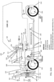
- FIG. 1 is a schematic diagram of an exemplary thermal management system for an electric vehicle illustrated in side view according to an example of the invention.
- an electric vehicle 100 includes a cabin 102, a chassis/body 103, wheels 104, a front powertrain 106, a rear powertrain 108, a front powertrain temperature sensor 110, a rear powertrain temperature sensor 114, a front powertrain microcontroller 112 and a rear powertrain microcontroller 116 (the microcontrollers comprising suitable computer processors and associated memory and circuitry), a high-voltage (HV) battery assembly 118 including an enclosure, the high- voltage battery assembly serving as an energy storage system as well as a battery for vehicle propulsion, and a high-voltage battery assembly temperature sensor 120.
- HV high-voltage
- the electric vehicle 100 also includes a battery management system 122, an onboard charger 124 and a direct current to direct current (DC/DC) converter 124', which provide suitable circuitry for charging the high-voltage battery, monitoring the state of charge and operation of the high-voltage battery, and for providing the appropriate voltage level to onboard electronic systems.
- a battery management system 122 an onboard charger 124 and a direct current to direct current (DC/DC) converter 124', which provide suitable circuitry for charging the high-voltage battery, monitoring the state of charge and operation of the high-voltage battery, and for providing the appropriate voltage level to onboard electronic systems.
- DC/DC direct current to direct current
- the electric vehicle 100 also includes an air conditioning system for providing environmental control for the cabin 102, including a front Heating, Ventilation, and Air Conditioning (HVAC) module 126, a cabin heat exchanger (heat pump) 128, a positive temperature coefficient heater 130, and air- conditioning (A/C) evaporator 132, and a blend door 134 that provides for blending and air mixture.
- HVAC Heating, Ventilation, and Air Conditioning
- A/C air- conditioning
- input air 136 is conditioned by the front HVAC module so as to generate output error 138 of a desired quality for the occupants of the cabin 102.
- the cabin 102 also includes a cabin temperature sensor 140 and a human machine interface (HMI) 142 at which an occupant may select the desired level of heating and/or air-conditioning.
- HMI human machine interface
- the vehicle also includes a cooling system that includes a radiator 150 (each may also be referred to as a low temperature radiator - LTR), cooling lines 152, an active grill shutter (AGS) 154 positioned in front of the radiator and controlled by a motor M or other suitable actuator, and a coolant reservoir 156.
- the coolant may be any suitable coolant such as conventional ethylene glycol/water mixture, and the refrigerant may be any suitable convention refrigerant.
- Air 157 may pass through the AGS 154 through the radiator 150 and a condenser 170 of a refrigerant system described below.
- the cooling lines 152 may be made of any suitable material such as copper tubing, stainless steel tubing, aluminum tubing, flexible polymer/rubber tubing, tubing of other materials, and any suitable combinations thereof. As illustrated in FIG. 1 , the cooling lines connect the radiator 150, the onboard charger 124, the DC/DC converter 124', the high-voltage battery assembly 118, the front and rear powertrains 106 and 108 (of which there may be four, one for each wheel), a coolant-refrigerant heat exchanger 162 (which may also be referred to as a chiller - CHLR), and valves VI 158 and V2 160.
- a coolant-refrigerant heat exchanger 162 which may also be referred to as a chiller - CHLR
- the heat exchanger 162 has associated with it an expansion valve 164 of a refrigerant system described below, which may be a thermal expansion valve (TXV) with a solenoid, or an electronic expansion valve (EXV).
- the cooling system also includes an electric water pump 166 for the high- voltage battery assembly 118 and an electric water pump 168 for the powertrain system 106 and 108.
- the vehicle 100 also includes a refrigeration system including a condenser 170, refrigerant lines 172, a fan 174, an electric A/C compressor (EAC) 176, and expansion valve 178, which may be a thermal expansion valve with a solenoid or an electronic expansion valve.
- the vehicle 100 also includes a powertrain control module (PCM) 190, which comprises one or more interfaces for receiving signals such as from temperature sensors 110, 114, 120, 140, 141 and a wireless transceiver 199 that communicates with a remote processing/monitoring system that monitors and communicates with the vehicle 100, one or more computer processors that processes signals onboard, and one or more interfaces that send control signals to various components of the vehicle 100 via electric control lines 192.
- PCM powertrain control module
- sensors may be provided such as refrigerant pressure sensors, cabin humidity sensors, voltage and current sensors for various electrical components including the high voltage battery, on-board charger, DC-DC converter, and the like. These and other sensors may provide signal inputs to the controller 190 and processed for decision making by the controller 190. These components to which signals may be sent from the PCM 190 include valves 158 and 160, pumps 166 and 168, microcontrollers 112 and 116, expansion valves 164 and 178, electric AC compressor 176, positive temperature coefficient heater 130, blend door 134, HMI 142, fan 172, and other components as may be suitable.
- FIG. 2 is a block diagram of an exemplary thermal management system for an electric vehicle according to an example of the invention.
- FIG. 2 presents many of the same components illustrated in FIG 1 , which are shown using the same reference numbers, descriptions of which were provided above
- FIG. 2 additionally shows that the vehicle 100 may include a rear HVAC module that includes an AC evaporator 132', a positive temperature coefficient heater 130', an expansion valve with an AC isolation solenoid 178', and a solenoid 179' which can condition input air 136' so as to provide output air 138' of desired heat or air conditioning for rear cabin occupants. Also as shown in FIG.
- the high-voltage battery assembly may include a positive temperature coefficient heater 125
- the powertrain system may also include a battery 127, a traction motor front axle including an inverter 108A, and a traction motor rear axle including an inverter 1 1 OA.
- the refrigerant system may also include an internal heat exchanger/suction line heat exchanger (THX/SLHX) 171.
- FIG. 3 illustrates a reference legend for the diagrams of FIGS. 1 and 2 for ease of reference.
- valves VI 158 and V2 160 may include, in some examples, valves VI 158 and V2 160.
- FIG. 4A illustrates an exemplary valve arrangement comprising two 3 -way valves for use in a thermal management system of an electric vehicle according to an example of the invention in such an embodiment.
- valve VI 158 includes 3 ports, one which aligns with the cooling line from the powertrain, one which aligns with the radiator (LTR) 150, and one which provides for bypassing the radiator 150.
- Valve V2 160 also includes 3 ports, one of which aligns with the cooling line from the powertrain, one of which is aligned with the cooling line to the place coolant circulation in a closed loop for the high-voltage battery assembly (as an energy storage system-ESS), and another which aligns with another cooling line to the high- voltage battery assembly 118 via certain components.
- FIG 4B illustrates a logic table for the two valves VI 158 and V2 160 that provide for four primary cooling States 1- 4, to be described in detail further below. As illustrated in FIG. 4B , each state has corresponding valve positions.
- port 1 of VI 158 is aligned with the cooling line from the power train and port 2 of VI 158 is aligned with bypassing the radiator (LTR) 150
- port 1 of V2 160 is aligned with another cooling line to the high-voltage battery assembly (ESS) 118 via certain components and port 2 of V2 160 is aligned with the cooling line to place coolant circulation in a closed loop for the high-voltage battery assembly (ESS CLOSED LOOP).
- port 1 of VI 158 is aligned with the cooling line from the power train and port 2 of VI 158 is aligned with the radiator (LTR) 150.
- port 1 of V2 160 is aligned with another cooling line to the high-voltage battery assembly (ESS) 118 via certain components and port 2 of V2 160 is aligned with the cooling line to place coolant circulation in a closed loop for the high-voltage battery assembly (ESS CLOSED LOOP).
- port 1 of VI 158 is aligned with the cooling line from the power train and port 2 of VI 158 is aligned with bypassing the radiator (LTR) 150.
- port 1 of V2 160 is aligned with another cooling line to the high-voltage battery assembly (ESS) 118 via certain components and port 2 of V2 160 is aligned with the cooling line from the power train.
- port 1 of VI 158 is aligned with the cooling line from the power train and port 2 of VI 158 is aligned with the radiator (LTR) 150.
- port 1 of V2 160 is aligned with another cooling line to the high-voltage battery assembly (ESS) 118 via certain components and port 2 of V2 160 is aligned with the cooling line from the power train.
- the four primary cooling states may also be achieved using a single 5-way valve body illustrated schematically in FIG. 4C (instead of two 3 -way valves as previously described) which has five associated ports: port 1 from the high-voltage battery assembly 118 (ESS), port 2 from the powertrain, port 3 aligned for closed- loop circulation at the high-voltage battery assembly 118 (ESS CLOSED-LOOP), port 4 bypassing the radiator 150 (LTR) and port 5 directed to the radiator 150 (LTR).
- FIG. 4C shows schematically the connections between the various ports responsible for the four primary states.
- FIG. 4D illustrates a logic table for the single 5-way valve that provides for the four primary cooling States 1-4 of FIG. 4C . For example, as illustrated in FIG.
- port 1 can be internally coupled to port 3 such that the high-voltage battery assembly 118 (ESS) is aligned with closed loop circulation at the high-voltage battery assembly 118 (ESS CLOSED-LOOP), port 2 can be internally coupled with port 4 such that the bypass of the radiator 150 (LTR) is aligned with the cooling line of the powertrain, and port 5 has no internal connections.
- ESS high-voltage battery assembly 118
- LTR bypass of the radiator 150
- port 1 can be internally coupled to port 3 such that the high-voltage battery assembly 118 (ESS) is aligned with closed loop circulation at the high-voltage battery assembly 118 (ESS CLOSED- LOOP), port 2 can be internally coupled to port 5 such that the high-voltage battery assembly 118 is aligned with the radiator 150 (LTR), and port 4 has no internal connections.
- port 1 can be internally coupled to both port 2 and port 4 such that the combination of the cooling line of the powertrain and the high-voltage battery assembly 118 are aligned with the bypass of radiator 1 0 and port 3 and port 5 have no internal connections
- FIG 4D also illustrates State 5 of FIG. 4C , where port 1 and port 2 are internally coupled with port 4 such that the combination of the cooling line of the powertrain and the high-voltage battery assembly 118 are aligned with the radiator 150 (LTR) and port 3 and port 4 have no internal connections.
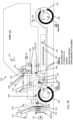
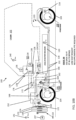
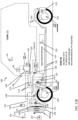
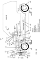
- FIGS. 5A-5D illustrate schematically four exemplary primary states of an exemplary thermal management system for the electric vehicle 100 according to examples of the invention.
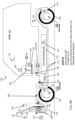
- a first primary state there are two distinct loops for coolant flow based on the position of valves VI 158 and V2 160. These loops are labeled ESS-CLOSED LOOP and PT-LTR (power train - low temperature radiator).
- ESS-CLOSED LOOP and PT-LTR (power train - low temperature radiator).
- PT-LTR power train - low temperature radiator
- coolant passes through the high-voltage battery assembly 118, through chiller 162 through valve V2 160, through pump 166 and through onboard charger/DC/DC converter 124/124'.
- coolant passes through the front and rear powertrains 106 and 108, through valve VI 158, and through pump 168.
- valves VI 158 and V2 160 lead to different states of coolant flow based on the various valve positions discussed in detail in FIGS. 4A-4D .
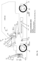
- coolant flowing through the high-voltage battery 118 does so according to the highlighted ESS-CLOSED LOOP, and coolant passing through the powertrain is directed by valve VI 158 through radiator 150 in a configuration labeled PT-LTR.
- PT-LTR a configuration labeled PT-LTR
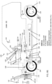
- coolant flowing through the high-voltage battery assembly 118 is open to the powertrain via valve V2 160 as shown by the labeling ESS-OPEN TO PT, and coolant passing through the powertrain bypasses the radiator 150 by virtue of valve VI 158.
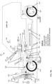
- a fourth primary state of coolant flow coolant flowing through the high-voltage battery assembly 118 is open to the powertrain via valve V2 160 as shown by the labeling ESS-OPEN TO PT, and coolant passing through the powertrain is directed by valve VI 158 through radiator 150 in a configuration labeled PT-LTR.
- FIGS. 6A-6D are schematic diagrams that correspond to FIGS. 5A-5D , respectively, which more sparsely illustrate exemplary coolant flow in first through fourth states, respectively, of an exemplary thermal management system for an electric vehicle in side view according to examples of the invention.
- FIG. 6A in a first primary state as previously described above with reference to FIG. 5A , there are two distinct loops for coolant flow based on the position of valves VI 158 and V2 160. These loops are labeled ESS-CLOSED LOOP and PT-LTR (power train - low temperature radiator).
- coolant passes through the high- voltage battery assembly 118, through chiller 162 through valve V2 160, through pump 166 and through onboard charger/DC/DC converter 124/124' .
- coolant passes through the front and rear powertrains 106 and 108, through valve VI 158, and through pump 168.
- Different positions of valves VI 158 and V2 160 lead to different states of coolant flow based on the various valve positions discussed in detail in FIGS. 4A-4D .
- FIG. 6B illustrates, as previously described above with reference to FIG.
- coolant flowing through the high-voltage battery 1 18 does so according to the highlighted ESS-CLOSED LOOP, and coolant passing through the powertrain is directed by valve VI 158 through radiator 150 in a configuration labeled PT-LTR.
- coolant flowing through the high-voltage battery assembly 118 is open to the powertrain via valve V2 160 as shown by the labeling ESS-OPEN TO PT, and coolant passing through the powertrain bypasses the radiator 150 by virtue of valve VI 158 FIG. 6D , as previously described above with reference to FIG.
- FIG. 5D illustrates a fourth primary state of coolant flow
- coolant flowing through the high- voltage battery assembly 118 is open to the powertrain via valve V2 160 as shown by the labeling ESS-OPEN TO PT, and coolant passing through the powertrain is directed by valve VI 158 through radiator 150 in a configuration labeled PT-LTR.
- FIGS. 7A-7G are schematic diagrams illustrating refrigerant flow for seven exemplary refrigerant flow states (State A - State G) according to examples of the invention.
- FIG. 7A illustrates a refrigerant flow state suitable for a high heat request, and supplemental heating via a PTC heater is required.
- refrigerant can flow along refrigerant lines 172 from condenser 170 through expansion valve 164 into coolant-refrigerant heat exchanger 162 (CHLR), subsequently through electric A/C compressor 176 into cabin heat exchanger (heat pump) 128 that can be modified via positive temperature coefficient heater 130, and back to condenser 170.
- CHLR coolant-refrigerant heat exchanger 162
- A/C compressor 176 cabin heat exchanger (heat pump) 128 that can be modified via positive temperature coefficient heater 130, and back to condenser 170.
- FIG. 7B illustrates a refrigerant flow state suitable for a low heat request and for which no supplemental heating from a PTC heater is required.
- refrigerant can flow along refrigerant lines 172 from condenser 170 through expansion valve 164 through coolant heat exchanger 162 (CHLR) through electric A/C compressor 176 into cabin heat exchanger (heat pump) 128 and from cabin heat exchanger (heat pump) 128 back to condenser 170.
- CHLR coolant heat exchanger 162
- refrigerant can also flow along refrigerant lines 172 from condenser 170 through expansion valve 178 into A/C evaporator 132, from A/C evaporator 132 through electric A/C compressor 176 into cabin heat exchanger (heat pump) 128 and subsequently back to condenser 170.
- FIG. 7C illustrates a refrigerant flow state suitable where there is an A/C request, e.g., from cabin 102.
- refrigerant can flow from condenser 170 along refrigerant lines 172 through expansion valve 178 into A/C evaporator 132, from into A/C evaporator 132 through electric A/C compressor 176 into cabin heat exchanger (heat pump) 128, from cabin heat exchanger (heat pump) 128 back to condenser 170.
- FIG. 7D illustrates a refrigerant flow state suitable for a high or low heat request and for which there is no activity required by the coolant-refrigerant heat exchanger 162.
- FIG. 7E illustrates a refrigerant flow state suitable for a high heat request and for which defrost is desired and supplemental heating via a PTC heater is required.
- refrigerant can flow along refrigerant lines 172 from condenser 170 through expansion valve 164 into coolant heat exchanger 162 (CHLR), from coolant heat exchanger 162 (CHLR) through electric A/C compressor 176 into cabin heat exchanger (heat pump) 128 that can be modified via positive temperature coefficient heater 130, and back to condenser 170.
- CHLR coolant heat exchanger 162
- A/C compressor 176 cabin heat exchanger (heat pump) 128 that can be modified via positive temperature coefficient heater 130, and back to condenser 170.
- refrigerant can flow along refrigerant lines 172 from condenser 170 through expansion valve 178 into A/C evaporator 132, from A/C evaporator 132 through electric A/C compressor 176 into cabin heat exchanger (heat pump) 128 that can be modified via positive temperature coefficient heater 130, and subsequently back to condenser 170.
- FIG. 7F illustrates a refrigerant flow state suitable for a low heat request and for which the frost is desired and no supplemental heating via a PTC heater is required.
- refrigerant can flow along refrigerant lines 172 from condenser 170 through expansion valve 164 into coolant heat exchanger 162 (CHLR), from coolant heat exchanger 162 through electric A/C compressor 176 into cabin heat exchanger (heat pump) 128 and from cabin heat exchanger (heat pump) 128 subsequently back to condenser 170.
- CHLR coolant heat exchanger 162
- A/C compressor 176 cabin heat exchanger (heat pump) 128 and from cabin heat exchanger (heat pump) 128 subsequently back to condenser 170.
- refrigerant can flow along refrigerant lines 172 from condenser 170 through expansion valve 178 into A/C evaporator 132, from A/C evaporator 132 through electric A/C compressor 176 into cabin heat exchanger (heat pump) 128 and back to condenser 170.
- FIG. 7G illustrates a refrigerant flow state suitable for a high or low heat request, and for which defrost is desired and for which there is no activity required by the coolant-refrigerant heat exchanger 162.
- refrigerant can flow along refrigerant lines 172 from condenser 170 through expansion valve 178 into A/C evaporator 132, through electric A/C compressor 176 into cabin heat exchanger (heat pump) 128 that can be modified via positive temperature coefficient heater 130, and subsequently back to condenser 170.
- discharge gas from electric A/C compressor 176 can be passed to the cabin heat exchanger 128 (CHX), where, when the HVAC module blend door 134 is not in “full cold” position, heat is exchanged (lost to) ambient air from outside which then passes to the cabin as “useful” heat. Where the blend door is in the "cold” position, no heat is exchanged. Refrigerant is then passed to the condenser 170 where full “condensation” takes place (if needed), or the AGS 154 can be closed to control the amount of subcooling.
- CHX cabin heat exchanger 128
- the high pressure liquid refrigerant then passes to the combo chiller/high pressure heat exchanger 162 and through the TXV 164 where heat from the ESS (and PT) glycol loops boil off the atomized refrigerant. This process can remove heat from the ESS and PT loops.
- Refrigerant may also be passed to the front HVAC module evaporator 132 to enable drying of the incoming cabin air for comfort and demist purposes.
- Rear/Aux AC isolation solenoid 178' could be disabled in a heat pump mode. If the CHX "air-off temperature" is below the target temperature, or the heat pump is not operational (e.g., ESS temperature or ambient too low), then the airside PTC heater 130 can be commanded ON and its duty cycle adjusted (via PID) to achieve target heater discharge temperature
- FIGS. 8A-8G are schematic diagrams illustrating coolant flow and refrigerant flow for seven exemplary sub-states (State 1 A - State 1G) for the first coolant flow state (State 1) described above in which HV battery energy storage system has a closed loop coolant configuration and in which the power train has a configuration where power train coolant bypasses the low temperature radiator.
- State 1 A - State 1G the first coolant flow state
- State 1G the first coolant flow state
- the sub-states represent the combination of primary coolant State 1 combined with the seven different refrigerant flow states described above in connection with FIGS. 7A-7G , exemplary conditions for which are also summarized in FIGS. 14A-14D .
- FIGS. 14A-14D are schematic diagrams illustrating coolant flow and refrigerant flow for seven exemplary sub-states for the first coolant flow state (State 1) described above in which HV battery energy storage system has a closed loop coolant configuration and in which the power train has a configuration where
- heading VI refers to VI 158 in FIGS. 1 and 5A-11G
- heading V2 refers to V2 160 in FIGS. 1 and 5A-11G
- heading EXV1 refers to expansion valve 164 in FIGS. 1 and 5A-11G
- heading EXV2 (Cabin) refers to expansion valve 178 in FIGS. 1 and 5A-11G , according to examples described herein.
- FIGS. 9A-9G are schematic diagrams illustrating coolant flow and refrigerant flow for seven other exemplary sub-states (State 2A - State 2G) for a second coolant flow state (State 2) in which HV battery energy storage system has a closed loop coolant configuration and in which the power train has a configuration where power train coolant is open to the low temperature radiator.
- State 2A - State 2G exemplary sub-states
- State 2G second coolant flow state
- the sub-states represent the combination of primary coolant State 2 combined with the seven different refrigerant flow states described above in connection with FIGS. 7A-7G , exemplary conditions for which are also summarized in FIGS. 14A-14D
- FIGS. 10A-10G are schematic diagrams illustrating coolant flow and refrigerant flow for seven other exemplary sub-states (State 3 A - State 3G) for a third coolant flow state (State 3) in which coolant for the HV battery energy storage system is open to the power train and in which the power train has a configuration where power train coolant bypasses the low temperature radiator.
- State 3 A - State 3G exemplary sub-states
- State 3 third coolant flow state
- the sub-states represent the combination of primary coolant State 3 combined with the seven different refrigerant flow states described above in connection with FIGS. 7A-7G , exemplary conditions for which are also summarized in FIGS. 14A-14D .
- FIGS. 11A-11G are schematic diagrams illustrating coolant flow and refrigerant flow for seven other exemplary sub-states (State 4A - State 4G) for a fourth coolant flow state (State 4) in which coolant for the HV battery energy storage system is open to the power train and in which the power train has a configuration where power train coolant is open to the low temperature radiator.
- State 4A - State 4G exemplary sub-states
- State 4G fourth coolant flow state
- the sub-states represent the combination of primary coolant State 4 combined with the seven different refrigerant flow states described above in connection with FIGS. 7A-7G , exemplary conditions for which are also summarized in FIGS. 14A-14D .
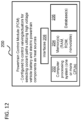
- FIG. 12 is a block diagram illustrating components of a power train control module 200 or controller for controlling coolant flow and refrigerant flow according to examples of the invention, such as powertrain control module 190 in FIG. 1 , which may be used control the methods and systems described herein, and which may comprise any suitable combination of hardware, software and/or firmware.
- the power train control module (PCM) 190, 200 may control suitable valves and actuators for selecting coolant paths utilizing high voltage vehicle battery and electric powertrain components as heat sources.
- PCM power train control module
- a PCM 200 may include a processing system 202, which may comprise one or more computer processing units, memory 204 such as random access memory, read only memory, nonvolatile memory, etc., one or more databases 206 store in memory that store information pertinent to the control of the vehicles cooling system, and one or more interfaces 208 suitable for acquiring data from various vehicle sensors, such as temperature sensors, and for controlling valves with suitable actuators to achieve the desired cooling and heating states.
- the computer processing system 202 may execute software operations, program instructions or routines to implement calculations and analyses. Such program instructions, accumulated data, and processed data may be stored one or more non-transitory computer-readable memories 204 and/or one or more in databases 206.
- the vehicle may communicate with remote databases and computer systems via a transceiver 199.
- the powertrain control module 190, 200 may include element managers, real-time data buffers, conveyors, file input processors, database indices, data buffers and data managers for managing data and processing.
- the human machine interface 142 which communicates with the powertrain control module 190, 200, may include displays, display interfaces, input/output devices such as button controls, dials, microphones, touchscreens and the like for permitting a user to select desired cabin environmental conditions.
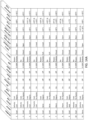
- FIGS. 14A-14D depict operational guidelines or conditions for how the exemplary coolant flow states and refrigerant flow states may be invoked by the controller 190 depending upon desired actions for the electric vehicle 100.
- the headings "Interior,” “Battery,” and “Powertrain Loop” reflect desired actions for each of these systems, which may be selected based on detected ambient environmental conditions, detected system conditions, as well as predictive analytics based upon the intended use of the vehicle, the vehicles location, weather conditions, road conditions, and the like.
- Exemplary states associated with identified conditions are also described for "Electric Air Conditioner Compressor” (on or off) (AC Compressor), “Air Positive Temperature Coefficient High Voltage Heater” (on or off) (PTC Heater), “Battery Heater” (on or off), “Active Grill Shutter” (0-100% open) (AGS), “Valve 1” and “Valve 2” (open, closed, or N/A which means it doesn't matter), “Chiller Valve (To CHLR)” (open or closed), and “Cabin Valve (To EVAP)” (open or closed).
- a position of the active grill shutter between 0% open and 100% open may be determined/chosen based on the external ambient temperature, the coolant temperature, the vehicle wind speed, etc., so as to achieve suitable heat dissipation at a radiator, e.g., as conventionally understood by those of skill in the art. For example, if the ambient temperature is 0 degrees C, the coolant temperature is 30 degrees C, and the vehicle is traveling 88 km/h (55 mph), the AGS can be set to 0% open (i.e., fully closed) to reduce aerodynamic drag while still achieving desired cooling of coolant at the radiator.
- coolant temperatures can be monitored at an input to the radiator and at an output to the radiator can be monitored via temperature sensors positioned at input and output locations, and the AGS percent opening can be controlled based on a difference between those measured temperatures in order to provide desired heat dissipation at the radiator.
- exemplary temperature ranges are identified for identified conditions, e.g., "Interior Temperature,” “Battery Loop Temperature,” and “Power Train Loop Temperature.” These temperatures are merely exemplary and other temperatures could be used depending upon the particular performance metrics of the various systems being controlled. For the temperatures shown in FIGS. 14A-14D , the values may be adjusted, for example, by ⁇ 10% in some examples, and by ⁇ 5 °C in other examples, for instance.
- Exemplary information in FIG.14 summarizes examples by which a controller can receive input signals, e.g., relating to temperature, and communicate output signals to actuators for valves and other components such as described herein to invoke certain states associated with the identified numbered conditions.
- condition 1 may be invoked by the controller to execute control signals such that the electric air conditioning compressor is on, the air positive temperature coefficient high voltage heater is off, the battery heater is off, valve 1 is set to bypass radiator, valve 2 is closed, chiller valve is open, and cabin valve is open.
- the order of importance for protecting vehicle' s systems and components can be based on operational constraints (i.e., sensitivity to extremes of temperatures and maintaining functionality), and overall system cost.
- the high voltage battery assembly 118 (as an ESS) is an expensive and typically the most critical system of the vehicle 100, and has a relatively narrow temperature band at which it can operate (approximately in the region of +5°C to 40°C) compared with the ambient temperature that the vehicle may be expected to be operational in.
- the powertrain systems are generally less sensitive to ambient temperatures, but may be more sensitive to the extremes of loading and duty cycles (e.g., towing, high speed, mountainous routes, etc., especially when combined with higher ambient temperatures).
- operational hierarchy for the vehicle' s thermal management system is based primarily on maintaining operator/passenger comfort at all ambient conditions (hot, cold, humidity, solar load, demist/defog) - the expectation is that the other systems (ESS and PT) are maintained within their respective operational limits, with no impact on passenger comfort.
- ESS and PT the other systems
- on-board electric energy stored in the HV battery system has to provide the means to maintain this comfort while minimizing impact on operational system performance and overall vehicle range.
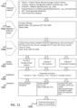
- FIG. 13 shows an operational flow diagram that illustrates various exemplary factors for controlling coolant and refrigerant states for an electric vehicle according to examples of the invention such as described above.
- the vehicle's thermal management system is continuously responding to dynamic and changing conditions via suitable sensors such as described above and including, e.g., external controls 1302 such as vehicle speed, load (gradient; uphill / downhill grade), ambient temperature, solar load, rain, humidity, electrical loads, etc., through sensing and processing carried out by PCM 190, 200.
- suitable sensors such as described above and including, e.g., external controls 1302 such as vehicle speed, load (gradient; uphill / downhill grade), ambient temperature, solar load, rain, humidity, electrical loads, etc.
- Additionally external controls at 1302 may include historical information of the vehicle such as expected locational or seasonal information, e.g., average, minimum, maximum expected temperature for a given location for a given date range, trending information such as seasonal information based on average past weather conditions, e.g., for a prior 24 hour period, predictive information such as weather forecasts, e.g., for an upcoming 24 hour period, programmable pre-conditioning information such as commute time windows, global positioning system (GPS) information such as route planning, and intended time-of- use charging information.
- expected locational or seasonal information e.g., average, minimum, maximum expected temperature for a given location for a given date range
- trending information such as seasonal information based on average past weather conditions, e.g., for a prior 24 hour period
- predictive information such as weather forecasts, e.g., for an upcoming 24 hour period
- programmable pre-conditioning information such as commute time windows
- GPS global positioning system
- the thermal management system can take inputs from many systems and determine the required outputs for the system' s actuators, e.g., evaluate sensors listed at 1304.
- the controls set points are determined continuously on a set of system calibrations which are arbitrated in the controller to ensure that each system is maintained at the optimum temperature, and this may be different depending on the season, geographic location, route, etc.
- the vehicle' s 100 satisfaction of desired performance factors can be desirable to prioritize, at 1305, the vehicle' s 100 satisfaction of desired performance factors according to certain rules. For example, it can be desirable to provide the desired cabin environment for the occupant as a first priority, then satisfy the high-voltage battery system requirements, then satisfy the powertrain system requirements. There is also an exception to adjust priority to configure the cooling and refrigerant systems to satisfy the most urgent need should there be a serious fault condition or extreme condition detected in either the high voltage battery system or the powertrain system. Powertrain functions as discussed above can determined by the PCM 190, 200 based on the set priority, at 1306, e.g., evaluate and apply arbitrator rules.
- various actuators can be controlled by the PCM 190, 200, at 1307, to correspond with the given powertrain functions and control various components.
- activation of one or more of active grill shutter (AGS) 154, fan 174, electric water pump 168, electric water pump 166, VI 158, V2, 160, solenoids at heat exchanger 162, solenoids at A/C evaporator 132, expansion valve 164, expansion valve 130, positive temperature coefficient heater 130, and/or electric A/C compressor 176 may be done to control the vehicle thermal management system as described herein.
- Ongoing sensing of vehicle parameters such as described above may be carried out with output therefrom being sent to controllers such as PCM 190 and/or PCM 200 for ongoing evaluation, at 1308.
- HV battery assembly 118 uses the HV battery assembly 118 as a thermal heat store, having a large capacity for storing heat, which differs from a conventional approach which uses outside air as a heat source, such as in a reverse cycle heat pump (with reversing valves and check valves). This can provide increased performance and increased efficiency since heat is taken from ESS and PT loops as opposed to relying exclusively on outside air and/or electrical cabin heating from stored battery charge.
- the high voltage battery assembly 118 can be preheated (preconditioned) using wall power and a battery heater to a maximum allowable battery temperature during cold climates to provide additional stored heat for the vehicle excursion reducing the need for relying the electrical charge of the battery itself for providing cabin heating.
- examples according to the invention may provide desirable advantages of avoiding reversing valves and may avoiding check valves at condenser evaporators and the chiller.
- the exemplary system utilizes heat (thermal energy) stored in the battery itself and waste heat from powertrain loop when loops are blended These exemplary approaches may provide improved vehicle range and overall efficiency for electric vehicles during "heating" season.
- the examples described herein may still also utilize outside air as a heat source or heat sink.
- the systems and methods may include and utilize data signals conveyed via networks (e.g., local area network, wide area network, internet, combinations thereof, etc.), fiber optic medium, carrier waves, wireless networks, etc. for communication with one or more data processing devices.
- the data signals can carry any or all of the data disclosed herein that is provided to or from a device.
- the methods and systems described herein may be implemented on many different types of processing devices by program code comprising program instructions that are executable by the device processing system.
- the software program instructions may include source code, object code, machine code, or any other stored data that is operable to cause a processing system to perform the methods and operations described herein. Any suitable computer languages may be used such as C, C++, Java, etc., as will be appreciated by those skilled in the art. Other implementations may also be used, however, such as firmware or even appropriately designed hardware configured to carry out the methods and systems described herein.
- the systems' and methods' data may be stored and implemented in one or more different types of computer-implemented data stores, such as different types of storage devices and programming constructs (e.g., RAM, ROM, Flash memory, flat files, databases, programming data structures, programming variables, IF-THEN (or similar type) statement constructs, etc.).
- storage devices and programming constructs e.g., RAM, ROM, Flash memory, flat files, databases, programming data structures, programming variables, IF-THEN (or similar type) statement constructs, etc.
- data structures describe formats for use in organizing and storing data in databases, programs, memory, or other non-transitory computer-readable media for use by a computer program.
- a module or processor includes but is not limited to a unit of code that performs a software operation, and can be implemented for example as a subroutine unit of code, or as a software function unit of code, or as an object (as in an object-oriented paradigm), or as an applet, or in a computer script language, or as another type of computer code.
- the software components and/or functionality may be located on a single computer or distributed across multiple computers depending upon the situation at hand.
Landscapes
- Engineering & Computer Science (AREA)
- Mechanical Engineering (AREA)
- Manufacturing & Machinery (AREA)
- General Chemical & Material Sciences (AREA)
- Electrochemistry (AREA)
- Chemical Kinetics & Catalysis (AREA)
- Chemical & Material Sciences (AREA)
- Thermal Sciences (AREA)
- Physics & Mathematics (AREA)
- Life Sciences & Earth Sciences (AREA)
- Transportation (AREA)
- Power Engineering (AREA)
- Sustainable Energy (AREA)
- Sustainable Development (AREA)
- Automation & Control Theory (AREA)
- Air-Conditioning For Vehicles (AREA)
- Electric Propulsion And Braking For Vehicles (AREA)
- Cooling, Air Intake And Gas Exhaust, And Fuel Tank Arrangements In Propulsion Units (AREA)
Description
- This application claims the benefit of
U. S. Provisional Patent Application No. 62/400,128 filed September 27, 2016 - The present invention relates to vehicles such as electric vehicles including hybrid vehicles and more particularly to thermal management systems and methods for such vehicles.
- Electric vehicles including hybrid vehicles are of great interest for transportation applications and can provide benefits of low or zero emissions, quiet operation and reduced dependence upon fossil fuels. However, conventional electric vehicles that rely primarily or exclusively on battery power for power train and propulsion may suffer degradation in vehicle range when the vehicle is operated near extremes of ambient environmental temperatures, particularly at colder temperatures.
-
US20160107502 describes an electric vehicle thermal management system that is useful to understand the invention. - The present inventor has observed a need for an enhanced thermal management system for electric vehicles that may mitigate degradation of the vehicle range due to extremes of environmental conditions. Exemplary approaches described herein may address such needs.
- According to the invention there is provided an automotive electric vehicle system as described in the accompanying claims.
- According to the invention as defined in
claim 1, an automotive electric vehicle system includes a high voltage battery system including an enclosure, an electric powertrain system, a radiator, coolant lines that permit coolant flow between the high voltage battery system, the power train system and the radiator, one or more valves for routing coolant along the coolant lines, and a controller configured to control the valves to facilitate the flow of coolant among a plurality of different, selectable coolant flow states involving the high voltage battery system, the powertrain system, and the radiator. - The heat transfer system for an electric vehicle includes coolant lines that permit flow of coolant between a high voltage battery system, a power train system, and a radiator. The heat transfer system also includes one or more valves for routing coolant along the coolant lines and a controller configured to control the valves to facilitate the flow of coolant among a plurality of different, selectable coolant flow states involving the high voltage battery system, the powertrain system, and the radiator. The high voltage battery system is configured to serve as a source of heat for another vehicle system.
- According to a method of controlling heat flow between systems of an electric automotive vehicle as defined in
claim 9, the method includes receiving, by at least one data processor, external data to the electric vehicle and sensor data from one or more sensors of the electric vehicle. The electric vehicle includes a high voltage battery system, a powertrain system, and a radiator. A coolant flow state is determined from a plurality of different, selectable coolant flow states involving the high voltage battery system, the powertrain system, and the radiator. Output is provided to a controller to facilitate control of the coolant flow state. -
-
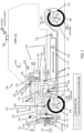
FIG. 1 is a schematic diagram of an exemplary thermal management system for an electric vehicle illustrated in side view according to an example of the invention. -
FIG. 2 is a block diagram of an exemplary thermal management system for an electric vehicle according to an example of the invention. -
FIG. 3 illustrates a legend for the diagrams ofFIGS 1 and2 . -
FIG. 4A illustrates an exemplary valve arrangement comprising two 3-way valves for use in a thermal management system of an electric vehicle according to an example of the invention. -
FIG. 4B illustrates an exemplary state table for the exemplary valve arrangement ofFIG. 4A . -
FIG. 4C illustrates an exemplary valve arrangement comprising a 5-way valve for use in a thermal management system of an electric vehicle according to an example of the invention. -
FIG. 4D illustrates an exemplary state table for the exemplary valve arrangement ofFIG. 4C . -
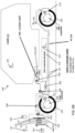
FIG. 5A is a schematic diagram illustrating exemplary coolant flow in a first state of an exemplary thermal management system for an electric vehicle in side view according to an example of the invention. -
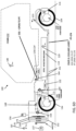
FIG. 5B is a schematic diagram illustrating exemplary coolant flow in a second state of an exemplary thermal management system for an electric vehicle in side view according to an example of the invention. -
FIG. 5C is a schematic diagram illustrating exemplary coolant flow in a third state of an exemplary thermal management system for an electric vehicle according to an example of the invention. -
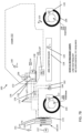
FIG. 5D is a schematic diagram illustrating exemplary coolant flow in a fourth state of an exemplary thermal management system for an electric vehicle in side view according to an example of the invention. -
FIGS. 6A-6D are schematic diagrams that correspond toFIGS. 5A-5D , respectively, and that more sparsely illustrate exemplary coolant flow in first through fourth states, respectively, of an exemplary thermal management system for an electric vehicle in side view according to examples of the invention. -
FIGS. 7A-7G are schematic diagrams illustrating refrigerant flow for seven exemplary refrigerant flow states (State A - State G) according to examples of the invention. -
FIGS. 8A-8G are schematic diagrams illustrating coolant flow and refrigerant flow for seven exemplary sub-states (State 1A - State 1G) for a first coolant flow state (State 1) in which HV battery energy storage system has a closed loop coolant configuration and in which the power train has a configuration where power train coolant bypasses the low temperature radiator. -
FIGS. 9A-9G are schematic diagrams illustrating coolant flow and refrigerant flow for seven other exemplary sub-states (State 2A - State 2G) for a second coolant flow state (State 2) in which HV battery energy storage system has a closed loop coolant configuration and in which the power train has a configuration where power train coolant is open to the low temperature radiator. -
FIGS. 10A-10G are schematic diagrams illustrating coolant flow and refrigerant flow for seven other exemplary sub-states (State 3 A - State 3G) for a third coolant flow state (State 3) in which coolant for the HV battery energy storage system is open to the power train and in which the power train has a configuration where power train coolant bypasses the low temperature radiator. -
FIGS. 11 A-11G are schematic diagrams illustrating coolant flow and refrigerant flow for seven other exemplary sub-states (State 4A -State 4G) for a fourth coolant flow state (State 4) in which coolant for the HV battery energy storage system is open to the power train and in which the power train has a configuration where power train coolant is open to the low temperature radiator. -
FIG. 12 is a block diagram illustrating components of a power train control module or controller for controlling coolant flow and refrigerant flow according to examples of the invention. -
FIG. 13 is an operational flow diagram that illustrates various exemplary factors for controlling coolant and refrigerant states for an electric vehicle according to examples of the invention. -
FIGS. 14A-14D depicts operational guidelines or conditions for how the exemplary coolant flow states and refrigerant flow states may be invoked by the controller depending upon desired actions for the electric vehicle. - As described in examples herein, increased performance and/or increased efficiency of an electric vehicle can be achieved by using a battery assembly of the electric vehicle as a thermal heat store and with which heat may be exchanged with other vehicle systems, such as a cabin climate control system. This differs from a conventional approach in which air may be used as a heat source, such as in a reverse cycle heat pump (with reversing valves and check valves). Taking heat from within the electric vehicle as opposed to relying exclusively on outside air and/or electrical cabin hearing from a stored battery charge can increase performance and/or efficiency of the electric vehicle. Of course, the examples described herein may still also utilize outside air as a heat source or heat sink. Additionally, preheating a battery assembly of an electric vehicle using wall power and/or a battery heater to bring the battery assembly to a maximum allowable temperature while in cold climates can provide for additional stored heat and can reduce the need for relying on the electrical charge of the battery to provide cabin heating.
-
FIG. 1 is a schematic diagram of an exemplary thermal management system for an electric vehicle illustrated in side view according to an example of the invention. As shown inFIG. 1 , anelectric vehicle 100 includes acabin 102, a chassis/body 103,wheels 104, afront powertrain 106, arear powertrain 108, a frontpowertrain temperature sensor 110, a rearpowertrain temperature sensor 114, afront powertrain microcontroller 112 and a rear powertrain microcontroller 116 (the microcontrollers comprising suitable computer processors and associated memory and circuitry), a high-voltage (HV)battery assembly 118 including an enclosure, the high- voltage battery assembly serving as an energy storage system as well as a battery for vehicle propulsion, and a high-voltage batteryassembly temperature sensor 120. Theelectric vehicle 100 also includes abattery management system 122, anonboard charger 124 and a direct current to direct current (DC/DC) converter 124', which provide suitable circuitry for charging the high-voltage battery, monitoring the state of charge and operation of the high-voltage battery, and for providing the appropriate voltage level to onboard electronic systems. - As shown in
FIG. 1 , theelectric vehicle 100 also includes an air conditioning system for providing environmental control for thecabin 102, including a front Heating, Ventilation, and Air Conditioning (HVAC)module 126, a cabin heat exchanger (heat pump) 128, a positivetemperature coefficient heater 130, and air- conditioning (A/C) evaporator 132, and ablend door 134 that provides for blending and air mixture. In this way,input air 136 is conditioned by the front HVAC module so as to generateoutput error 138 of a desired quality for the occupants of thecabin 102. Thecabin 102 also includes acabin temperature sensor 140 and a human machine interface (HMI) 142 at which an occupant may select the desired level of heating and/or air-conditioning. - The vehicle also includes a cooling system that includes a radiator 150 (each may also be referred to as a low temperature radiator - LTR), cooling
lines 152, an active grill shutter (AGS) 154 positioned in front of the radiator and controlled by a motor M or other suitable actuator, and acoolant reservoir 156. The coolant may be any suitable coolant such as conventional ethylene glycol/water mixture, and the refrigerant may be any suitable convention refrigerant.Air 157 may pass through theAGS 154 through theradiator 150 and acondenser 170 of a refrigerant system described below. The cooling lines 152 may be made of any suitable material such as copper tubing, stainless steel tubing, aluminum tubing, flexible polymer/rubber tubing, tubing of other materials, and any suitable combinations thereof. As illustrated inFIG. 1 , the cooling lines connect theradiator 150, theonboard charger 124, the DC/DC converter 124', the high-voltage battery assembly 118, the front andrear powertrains 106 and 108 (of which there may be four, one for each wheel), a coolant-refrigerant heat exchanger 162 (which may also be referred to as a chiller - CHLR), andvalves VI 158 andV2 160. Theheat exchanger 162 has associated with it anexpansion valve 164 of a refrigerant system described below, which may be a thermal expansion valve (TXV) with a solenoid, or an electronic expansion valve (EXV). The cooling system also includes anelectric water pump 166 for the high-voltage battery assembly 118 and anelectric water pump 168 for thepowertrain system - The
vehicle 100 also includes a refrigeration system including acondenser 170,refrigerant lines 172, afan 174, an electric A/C compressor (EAC) 176, andexpansion valve 178, which may be a thermal expansion valve with a solenoid or an electronic expansion valve. Thevehicle 100 also includes a powertrain control module (PCM) 190, which comprises one or more interfaces for receiving signals such as fromtemperature sensors wireless transceiver 199 that communicates with a remote processing/monitoring system that monitors and communicates with thevehicle 100, one or more computer processors that processes signals onboard, and one or more interfaces that send control signals to various components of thevehicle 100 via electric control lines 192. Though not shown, other types of sensors may be provided such as refrigerant pressure sensors, cabin humidity sensors, voltage and current sensors for various electrical components including the high voltage battery, on-board charger, DC-DC converter, and the like. These and other sensors may provide signal inputs to thecontroller 190 and processed for decision making by thecontroller 190. These components to which signals may be sent from thePCM 190 includevalves microcontrollers expansion valves electric AC compressor 176, positivetemperature coefficient heater 130,blend door 134,HMI 142,fan 172, and other components as may be suitable. -
FIG. 2 is a block diagram of an exemplary thermal management system for an electric vehicle according to an example of the invention.FIG. 2 presents many of the same components illustrated inFIG 1 , which are shown using the same reference numbers, descriptions of which were provided aboveFIG. 2 additionally shows that thevehicle 100 may include a rear HVAC module that includes an AC evaporator 132', a positive temperature coefficient heater 130', an expansion valve with an AC isolation solenoid 178', and a solenoid 179' which can condition input air 136' so as to provide output air 138' of desired heat or air conditioning for rear cabin occupants. Also as shown inFIG. 2 the high-voltage battery assembly may include a positivetemperature coefficient heater 125 The powertrain system may also include abattery 127, a traction motor front axle including aninverter 108A, and a traction motor rear axle including aninverter 1 1 OA. As shown inFIG. 2 the refrigerant system may also include an internal heat exchanger/suction line heat exchanger (THX/SLHX) 171. -
FIG. 3 illustrates a reference legend for the diagrams ofFIGS. 1 and2 for ease of reference. - As noted above, the cooling system for the
electric vehicle 100 may include, in some examples,valves VI 158 andV2 160.FIG. 4A illustrates an exemplary valve arrangement comprising two 3 -way valves for use in a thermal management system of an electric vehicle according to an example of the invention in such an embodiment. As shown inFIG. 4A ,valve VI 158 includes 3 ports, one which aligns with the cooling line from the powertrain, one which aligns with the radiator (LTR) 150, and one which provides for bypassing theradiator 150.Valve V2 160 also includes 3 ports, one of which aligns with the cooling line from the powertrain, one of which is aligned with the cooling line to the place coolant circulation in a closed loop for the high-voltage battery assembly (as an energy storage system-ESS), and another which aligns with another cooling line to the high-voltage battery assembly 118 via certain components.FIG 4B illustrates a logic table for the two valves VI 158 andV2 160 that provide for four primary cooling States 1- 4, to be described in detail further below. As illustrated inFIG. 4B , each state has corresponding valve positions. For example, inState 1,port 1 ofVI 158 is aligned with the cooling line from the power train andport 2 ofVI 158 is aligned with bypassing the radiator (LTR) 150, Also inState 1,port 1 ofV2 160 is aligned with another cooling line to the high-voltage battery assembly (ESS) 118 via certain components andport 2 ofV2 160 is aligned with the cooling line to place coolant circulation in a closed loop for the high-voltage battery assembly (ESS CLOSED LOOP). Corresponding toState 2, as illustrated inFIG. 4B ,port 1 ofVI 158 is aligned with the cooling line from the power train andport 2 ofVI 158 is aligned with the radiator (LTR) 150. Also inState 2,port 1 ofV2 160 is aligned with another cooling line to the high-voltage battery assembly (ESS) 118 via certain components andport 2 ofV2 160 is aligned with the cooling line to place coolant circulation in a closed loop for the high-voltage battery assembly (ESS CLOSED LOOP). With respect toState 3, as illustrated inFIG. 4B , similar toState 1,port 1 ofVI 158 is aligned with the cooling line from the power train andport 2 ofVI 158 is aligned with bypassing the radiator (LTR) 150. Also inState 3,port 1 ofV2 160 is aligned with another cooling line to the high-voltage battery assembly (ESS) 118 via certain components andport 2 ofV2 160 is aligned with the cooling line from the power train. As illustrated inFIG. 4B , inState 4,port 1 ofVI 158 is aligned with the cooling line from the power train andport 2 ofVI 158 is aligned with the radiator (LTR) 150. Also inState 4, similar toState 3,port 1 ofV2 160 is aligned with another cooling line to the high-voltage battery assembly (ESS) 118 via certain components andport 2 ofV2 160 is aligned with the cooling line from the power train. - The four primary cooling states may also be achieved using a single 5-way valve body illustrated schematically in
FIG. 4C (instead of two 3 -way valves as previously described) which has five associated ports:port 1 from the high-voltage battery assembly 118 (ESS),port 2 from the powertrain,port 3 aligned for closed- loop circulation at the high-voltage battery assembly 118 (ESS CLOSED-LOOP),port 4 bypassing the radiator 150 (LTR) andport 5 directed to the radiator 150 (LTR).FIG. 4C shows schematically the connections between the various ports responsible for the four primary states.FIG. 4D illustrates a logic table for the single 5-way valve that provides for the four primary cooling States 1-4 ofFIG. 4C . For example, as illustrated inFIG. 4D , corresponding toState 1,port 1 can be internally coupled toport 3 such that the high-voltage battery assembly 118 (ESS) is aligned with closed loop circulation at the high-voltage battery assembly 118 (ESS CLOSED-LOOP),port 2 can be internally coupled withport 4 such that the bypass of the radiator 150 (LTR) is aligned with the cooling line of the powertrain, andport 5 has no internal connections. As illustrated inFIG. 4D , forState 2 ofFIG. 4C ,port 1 can be internally coupled toport 3 such that the high-voltage battery assembly 118 (ESS) is aligned with closed loop circulation at the high-voltage battery assembly 118 (ESS CLOSED- LOOP),port 2 can be internally coupled toport 5 such that the high-voltage battery assembly 118 is aligned with the radiator 150 (LTR), andport 4 has no internal connections. ForState 3 ofFIG. 4C , as illustrated inFIG. 4D ,port 1 can be internally coupled to bothport 2 andport 4 such that the combination of the cooling line of the powertrain and the high-voltage battery assembly 118 are aligned with the bypass ofradiator 1 0 andport 3 andport 5 have no internal connectionsFIG 4D also illustratesState 5 ofFIG. 4C , whereport 1 andport 2 are internally coupled withport 4 such that the combination of the cooling line of the powertrain and the high-voltage battery assembly 118 are aligned with the radiator 150 (LTR) andport 3 andport 4 have no internal connections. -
FIGS. 5A-5D illustrate schematically four exemplary primary states of an exemplary thermal management system for theelectric vehicle 100 according to examples of the invention. As shown inFIG. 5A , in a first primary state, there are two distinct loops for coolant flow based on the position of valves VI 158 andV2 160. These loops are labeled ESS-CLOSED LOOP and PT-LTR (power train - low temperature radiator). For the first loop, coolant passes through the high-voltage battery assembly 118, throughchiller 162 throughvalve V2 160, throughpump 166 and through onboard charger/DC/DC converter 124/124'. For the second loop, coolant passes through the front andrear powertrains pump 168. Different positions of valves VI 158 andV2 160 lead to different states of coolant flow based on the various valve positions discussed in detail inFIGS. 4A-4D . As shown inFIG. 5B , in a second primary state of coolant flow, coolant flowing through the high-voltage battery 118 does so according to the highlighted ESS-CLOSED LOOP, and coolant passing through the powertrain is directed by valve VI 158 throughradiator 150 in a configuration labeled PT-LTR. As shown inFIG. 5C , in a third primary state of coolant flow, coolant flowing through the high-voltage battery assembly 118 is open to the powertrain viavalve V2 160 as shown by the labeling ESS-OPEN TO PT, and coolant passing through the powertrain bypasses theradiator 150 by virtue of valve VI 158. As shown inFIG. 5D , a fourth primary state of coolant flow, coolant flowing through the high-voltage battery assembly 118 is open to the powertrain viavalve V2 160 as shown by the labeling ESS-OPEN TO PT, and coolant passing through the powertrain is directed by valve VI 158 throughradiator 150 in a configuration labeled PT-LTR. -
FIGS. 6A-6D are schematic diagrams that correspond toFIGS. 5A-5D , respectively, which more sparsely illustrate exemplary coolant flow in first through fourth states, respectively, of an exemplary thermal management system for an electric vehicle in side view according to examples of the invention. As shown inFIG. 6A , in a first primary state as previously described above with reference toFIG. 5A , there are two distinct loops for coolant flow based on the position of valves VI 158 andV2 160. These loops are labeled ESS-CLOSED LOOP and PT-LTR (power train - low temperature radiator). For the first loop, coolant passes through the high-voltage battery assembly 118, throughchiller 162 throughvalve V2 160, throughpump 166 and through onboard charger/DC/DC converter 124/124' . For the second loop, coolant passes through the front andrear powertrains pump 168. Different positions of valves VI 158 andV2 160 lead to different states of coolant flow based on the various valve positions discussed in detail inFIGS. 4A-4D .FIG. 6B illustrates, as previously described above with reference toFIG. 5B , in a second primary state of coolant flow, coolant flowing through the high-voltage battery 1 18 does so according to the highlighted ESS-CLOSED LOOP, and coolant passing through the powertrain is directed by valve VI 158 throughradiator 150 in a configuration labeled PT-LTR. As illustrated inFIG. 6C , corresponding to the previous description ofFIG. 5C , in a third primary state of coolant flow, coolant flowing through the high-voltage battery assembly 118 is open to the powertrain viavalve V2 160 as shown by the labeling ESS-OPEN TO PT, and coolant passing through the powertrain bypasses theradiator 150 by virtue of valve VI 158FIG. 6D , as previously described above with reference toFIG. 5D , illustrates a fourth primary state of coolant flow, coolant flowing through the high-voltage battery assembly 118 is open to the powertrain viavalve V2 160 as shown by the labeling ESS-OPEN TO PT, and coolant passing through the powertrain is directed by valve VI 158 throughradiator 150 in a configuration labeled PT-LTR. -
FIGS. 7A-7G are schematic diagrams illustrating refrigerant flow for seven exemplary refrigerant flow states (State A - State G) according to examples of the invention.FIG. 7A illustrates a refrigerant flow state suitable for a high heat request, and supplemental heating via a PTC heater is required. For example, refrigerant can flow alongrefrigerant lines 172 fromcondenser 170 throughexpansion valve 164 into coolant-refrigerant heat exchanger 162 (CHLR), subsequently through electric A/C compressor 176 into cabin heat exchanger (heat pump) 128 that can be modified via positivetemperature coefficient heater 130, and back tocondenser 170. -
FIG. 7B illustrates a refrigerant flow state suitable for a low heat request and for which no supplemental heating from a PTC heater is required. For example, along one loop, refrigerant can flow alongrefrigerant lines 172 fromcondenser 170 throughexpansion valve 164 through coolant heat exchanger 162 (CHLR) through electric A/C compressor 176 into cabin heat exchanger (heat pump) 128 and from cabin heat exchanger (heat pump) 128 back tocondenser 170. Additionally, following another loop refrigerant can also flow alongrefrigerant lines 172 fromcondenser 170 throughexpansion valve 178 into A/C evaporator 132, from A/C evaporator 132 through electric A/C compressor 176 into cabin heat exchanger (heat pump) 128 and subsequently back tocondenser 170. -
FIG. 7C illustrates a refrigerant flow state suitable where there is an A/C request, e.g., fromcabin 102. Along one loop, refrigerant can flow fromcondenser 170 alongrefrigerant lines 172 throughexpansion valve 178 into A/C evaporator 132, from into A/C evaporator 132 through electric A/C compressor 176 into cabin heat exchanger (heat pump) 128, from cabin heat exchanger (heat pump) 128 back tocondenser 170. -
FIG. 7D illustrates a refrigerant flow state suitable for a high or low heat request and for which there is no activity required by the coolant-refrigerant heat exchanger 162.FIG. 7E illustrates a refrigerant flow state suitable for a high heat request and for which defrost is desired and supplemental heating via a PTC heater is required. For example, following one loop, refrigerant can flow alongrefrigerant lines 172 fromcondenser 170 throughexpansion valve 164 into coolant heat exchanger 162 (CHLR), from coolant heat exchanger 162 (CHLR) through electric A/C compressor 176 into cabin heat exchanger (heat pump) 128 that can be modified via positivetemperature coefficient heater 130, and back tocondenser 170. Following another loop, refrigerant can flow alongrefrigerant lines 172 fromcondenser 170 throughexpansion valve 178 into A/C evaporator 132, from A/C evaporator 132 through electric A/C compressor 176 into cabin heat exchanger (heat pump) 128 that can be modified via positivetemperature coefficient heater 130, and subsequently back tocondenser 170. -
FIG. 7F illustrates a refrigerant flow state suitable for a low heat request and for which the frost is desired and no supplemental heating via a PTC heater is required. For example, following one loop, refrigerant can flow alongrefrigerant lines 172 fromcondenser 170 throughexpansion valve 164 into coolant heat exchanger 162 (CHLR), fromcoolant heat exchanger 162 through electric A/C compressor 176 into cabin heat exchanger (heat pump) 128 and from cabin heat exchanger (heat pump) 128 subsequently back tocondenser 170. Following another loop, refrigerant can flow alongrefrigerant lines 172 fromcondenser 170 throughexpansion valve 178 into A/C evaporator 132, from A/C evaporator 132 through electric A/C compressor 176 into cabin heat exchanger (heat pump) 128 and back tocondenser 170. -
FIG. 7G illustrates a refrigerant flow state suitable for a high or low heat request, and for which defrost is desired and for which there is no activity required by the coolant-refrigerant heat exchanger 162. For example, refrigerant can flow alongrefrigerant lines 172 fromcondenser 170 throughexpansion valve 178 into A/C evaporator 132, through electric A/C compressor 176 into cabin heat exchanger (heat pump) 128 that can be modified via positivetemperature coefficient heater 130, and subsequently back tocondenser 170. - In exemplary operation, discharge gas from electric A/C compressor 176 (eAC) can be passed to the cabin heat exchanger 128 (CHX), where, when the HVAC
module blend door 134 is not in "full cold" position, heat is exchanged (lost to) ambient air from outside which then passes to the cabin as "useful" heat. Where the blend door is in the "cold" position, no heat is exchanged. Refrigerant is then passed to thecondenser 170 where full "condensation" takes place (if needed), or theAGS 154 can be closed to control the amount of subcooling. The high pressure liquid refrigerant then passes to the combo chiller/highpressure heat exchanger 162 and through theTXV 164 where heat from the ESS (and PT) glycol loops boil off the atomized refrigerant. This process can remove heat from the ESS and PT loops. - Refrigerant may also be passed to the front
HVAC module evaporator 132 to enable drying of the incoming cabin air for comfort and demist purposes. Rear/Aux AC isolation solenoid 178' could be disabled in a heat pump mode. If the CHX "air-off temperature" is below the target temperature, or the heat pump is not operational (e.g., ESS temperature or ambient too low), then theairside PTC heater 130 can be commanded ON and its duty cycle adjusted (via PID) to achieve target heater discharge temperature -
FIGS. 8A-8G are schematic diagrams illustrating coolant flow and refrigerant flow for seven exemplary sub-states (State 1 A - State 1G) for the first coolant flow state (State 1) described above in which HV battery energy storage system has a closed loop coolant configuration and in which the power train has a configuration where power train coolant bypasses the low temperature radiator. These sub-states are listed in the figures as States 1A-1G, and have associated conditions listed on the respective figures. The sub-states represent the combination ofprimary coolant State 1 combined with the seven different refrigerant flow states described above in connection withFIGS. 7A-7G , exemplary conditions for which are also summarized inFIGS. 14A-14D . InFIGS. 14A-14D , it should be understood that the heading VI refers toVI 158 inFIGS. 1 and5A-11G , heading V2 refers toV2 160 inFIGS. 1 and5A-11G , heading EXV1 (Chiller) refers toexpansion valve 164 inFIGS. 1 and5A-11G , and heading EXV2 (Cabin) refers toexpansion valve 178 inFIGS. 1 and5A-11G , according to examples described herein. -
FIGS. 9A-9G are schematic diagrams illustrating coolant flow and refrigerant flow for seven other exemplary sub-states (State 2A - State 2G) for a second coolant flow state (State 2) in which HV battery energy storage system has a closed loop coolant configuration and in which the power train has a configuration where power train coolant is open to the low temperature radiator. These sub-states are listed in the figures as States 2A-2G, and have associated conditions listed on the respective figures The sub-states represent the combination ofprimary coolant State 2 combined with the seven different refrigerant flow states described above in connection withFIGS. 7A-7G , exemplary conditions for which are also summarized inFIGS. 14A-14D -
FIGS. 10A-10G are schematic diagrams illustrating coolant flow and refrigerant flow for seven other exemplary sub-states (State 3 A - State 3G) for a third coolant flow state (State 3) in which coolant for the HV battery energy storage system is open to the power train and in which the power train has a configuration where power train coolant bypasses the low temperature radiator. These sub-states are listed in the figures asStates 3A-3G, and have associated conditions listed on the respective figures. The sub-states represent the combination ofprimary coolant State 3 combined with the seven different refrigerant flow states described above in connection withFIGS. 7A-7G , exemplary conditions for which are also summarized inFIGS. 14A-14D . -
FIGS. 11A-11G are schematic diagrams illustrating coolant flow and refrigerant flow for seven other exemplary sub-states (State 4A -State 4G) for a fourth coolant flow state (State 4) in which coolant for the HV battery energy storage system is open to the power train and in which the power train has a configuration where power train coolant is open to the low temperature radiator. These sub-states are listed in the figures as States 4A-4G, and have associated conditions listed on the respective figures. The sub-states represent the combination ofprimary coolant State 4 combined with the seven different refrigerant flow states described above in connection withFIGS. 7A-7G , exemplary conditions for which are also summarized inFIGS. 14A-14D . -
FIG. 12 is a block diagram illustrating components of a powertrain control module 200 or controller for controlling coolant flow and refrigerant flow according to examples of the invention, such aspowertrain control module 190 inFIG. 1 , which may be used control the methods and systems described herein, and which may comprise any suitable combination of hardware, software and/or firmware. As shown inFIGS. 1 and12 , the power train control module (PCM) 190, 200 may control suitable valves and actuators for selecting coolant paths utilizing high voltage vehicle battery and electric powertrain components as heat sources. As shown inFIG. 12 , aPCM 200 may include aprocessing system 202, which may comprise one or more computer processing units,memory 204 such as random access memory, read only memory, nonvolatile memory, etc., one ormore databases 206 store in memory that store information pertinent to the control of the vehicles cooling system, and one ormore interfaces 208 suitable for acquiring data from various vehicle sensors, such as temperature sensors, and for controlling valves with suitable actuators to achieve the desired cooling and heating states. Thecomputer processing system 202 may execute software operations, program instructions or routines to implement calculations and analyses. Such program instructions, accumulated data, and processed data may be stored one or more non-transitory computer-readable memories 204 and/or one or more indatabases 206. The vehicle may communicate with remote databases and computer systems via atransceiver 199. - The
powertrain control module human machine interface 142, which communicates with thepowertrain control module -
FIGS. 14A-14D depict operational guidelines or conditions for how the exemplary coolant flow states and refrigerant flow states may be invoked by thecontroller 190 depending upon desired actions for theelectric vehicle 100. For example, the headings "Interior," "Battery," and "Powertrain Loop" reflect desired actions for each of these systems, which may be selected based on detected ambient environmental conditions, detected system conditions, as well as predictive analytics based upon the intended use of the vehicle, the vehicles location, weather conditions, road conditions, and the like. Exemplary states associated with identified conditions are also described for "Electric Air Conditioner Compressor" (on or off) (AC Compressor), "Air Positive Temperature Coefficient High Voltage Heater" (on or off) (PTC Heater), "Battery Heater" (on or off), "Active Grill Shutter" (0-100% open) (AGS), "Valve 1" and "Valve 2" (open, closed, or N/A which means it doesn't matter), "Chiller Valve (To CHLR)" (open or closed), and "Cabin Valve (To EVAP)" (open or closed). Regarding the active grill shutter (AGS), a position of the active grill shutter between 0% open and 100% open may be determined/chosen based on the external ambient temperature, the coolant temperature, the vehicle wind speed, etc., so as to achieve suitable heat dissipation at a radiator, e.g., as conventionally understood by those of skill in the art. For example, if the ambient temperature is 0 degrees C, the coolant temperature is 30 degrees C, and the vehicle is traveling 88 km/h (55 mph), the AGS can be set to 0% open (i.e., fully closed) to reduce aerodynamic drag while still achieving desired cooling of coolant at the radiator. Moreover, coolant temperatures can be monitored at an input to the radiator and at an output to the radiator can be monitored via temperature sensors positioned at input and output locations, and the AGS percent opening can be controlled based on a difference between those measured temperatures in order to provide desired heat dissipation at the radiator. In addition, exemplary temperature ranges are identified for identified conditions, e.g., "Interior Temperature," "Battery Loop Temperature," and "Power Train Loop Temperature." These temperatures are merely exemplary and other temperatures could be used depending upon the particular performance metrics of the various systems being controlled. For the temperatures shown inFIGS. 14A-14D , the values may be adjusted, for example, by ± 10% in some examples, and by ± 5 °C in other examples, for instance. Exemplary information inFIG.14 summarizes examples by which a controller can receive input signals, e.g., relating to temperature, and communicate output signals to actuators for valves and other components such as described herein to invoke certain states associated with the identified numbered conditions. For example, with reference to the first row ofFIG. 14A , if the interior temperature is detected as >20°C, the battery temperature is detected as >30°C, and the powertrain temperature is detected as ≤55°C,condition 1 may be invoked by the controller to execute control signals such that the electric air conditioning compressor is on, the air positive temperature coefficient high voltage heater is off, the battery heater is off,valve 1 is set to bypass radiator,valve 2 is closed, chiller valve is open, and cabin valve is open. - The order of importance for protecting vehicle' s systems and components can be based on operational constraints (i.e., sensitivity to extremes of temperatures and maintaining functionality), and overall system cost. The high voltage battery assembly 118 (as an ESS) is an expensive and typically the most critical system of the
vehicle 100, and has a relatively narrow temperature band at which it can operate (approximately in the region of +5°C to 40°C) compared with the ambient temperature that the vehicle may be expected to be operational in. This is followed by the powertrain systems (the inverter, motor, power electronics including the DC-DC converter, on-board charger), however, the powertrain systems are generally less sensitive to ambient temperatures, but may be more sensitive to the extremes of loading and duty cycles (e.g., towing, high speed, mountainous routes, etc., especially when combined with higher ambient temperatures). - However, operational hierarchy for the vehicle' s thermal management system is based primarily on maintaining operator/passenger comfort at all ambient conditions (hot, cold, humidity, solar load, demist/defog) - the expectation is that the other systems (ESS and PT) are maintained within their respective operational limits, with no impact on passenger comfort. In an electric vehicle, on-board electric energy stored in the HV battery system has to provide the means to maintain this comfort while minimizing impact on operational system performance and overall vehicle range.
-
FIG. 13 shows an operational flow diagram that illustrates various exemplary factors for controlling coolant and refrigerant states for an electric vehicle according to examples of the invention such as described above. The vehicle's thermal management system is continuously responding to dynamic and changing conditions via suitable sensors such as described above and including, e.g.,external controls 1302 such as vehicle speed, load (gradient; uphill / downhill grade), ambient temperature, solar load, rain, humidity, electrical loads, etc., through sensing and processing carried out byPCM - Thus, as a general matter, it can be desirable to prioritize, at 1305, the vehicle'
s 100 satisfaction of desired performance factors according to certain rules. For example, it can be desirable to provide the desired cabin environment for the occupant as a first priority, then satisfy the high-voltage battery system requirements, then satisfy the powertrain system requirements. There is also an exception to adjust priority to configure the cooling and refrigerant systems to satisfy the most urgent need should there be a serious fault condition or extreme condition detected in either the high voltage battery system or the powertrain system. Powertrain functions as discussed above can determined by thePCM PCM fan 174,electric water pump 168,electric water pump 166,VI 158, V2, 160, solenoids atheat exchanger 162, solenoids at A/C evaporator 132,expansion valve 164,expansion valve 130, positivetemperature coefficient heater 130, and/or electric A/C compressor 176 may be done to control the vehicle thermal management system as described herein. Ongoing sensing of vehicle parameters such as described above may be carried out with output therefrom being sent to controllers such asPCM 190 and/orPCM 200 for ongoing evaluation, at 1308. - It will be appreciated that examples described herein use the
HV battery assembly 118 as a thermal heat store, having a large capacity for storing heat, which differs from a conventional approach which uses outside air as a heat source, such as in a reverse cycle heat pump (with reversing valves and check valves). This can provide increased performance and increased efficiency since heat is taken from ESS and PT loops as opposed to relying exclusively on outside air and/or electrical cabin heating from stored battery charge. Also, the highvoltage battery assembly 118 can be preheated (preconditioned) using wall power and a battery heater to a maximum allowable battery temperature during cold climates to provide additional stored heat for the vehicle excursion reducing the need for relying the electrical charge of the battery itself for providing cabin heating. It should be appreciated that examples according to the invention may provide desirable advantages of avoiding reversing valves and may avoiding check valves at condenser evaporators and the chiller. Also, the exemplary system utilizes heat (thermal energy) stored in the battery itself and waste heat from powertrain loop when loops are blended These exemplary approaches may provide improved vehicle range and overall efficiency for electric vehicles during "heating" season. Of course, the examples described herein may still also utilize outside air as a heat source or heat sink. - This written description describes exemplary embodiments of the invention, but other variations fall within scope of the invention within the scope of the appended claims. For example, the systems and methods may include and utilize data signals conveyed via networks (e.g., local area network, wide area network, internet, combinations thereof, etc.), fiber optic medium, carrier waves, wireless networks, etc. for communication with one or more data processing devices. The data signals can carry any or all of the data disclosed herein that is provided to or from a device.
- The methods and systems described herein may be implemented on many different types of processing devices by program code comprising program instructions that are executable by the device processing system. The software program instructions may include source code, object code, machine code, or any other stored data that is operable to cause a processing system to perform the methods and operations described herein. Any suitable computer languages may be used such as C, C++, Java, etc., as will be appreciated by those skilled in the art. Other implementations may also be used, however, such as firmware or even appropriately designed hardware configured to carry out the methods and systems described herein.
- The systems' and methods' data (e.g., associations, mappings, data input, data output, intermediate data results, final data results, etc.) may be stored and implemented in one or more different types of computer-implemented data stores, such as different types of storage devices and programming constructs (e.g., RAM, ROM, Flash memory, flat files, databases, programming data structures, programming variables, IF-THEN (or similar type) statement constructs, etc.). It is noted that data structures describe formats for use in organizing and storing data in databases, programs, memory, or other non-transitory computer-readable media for use by a computer program.
- The computer components, software modules, functions, data stores and data structures described herein may be connected directly or indirectly to each other in order to allow the flow of data needed for their operations. It is also noted that a module or processor includes but is not limited to a unit of code that performs a software operation, and can be implemented for example as a subroutine unit of code, or as a software function unit of code, or as an object (as in an object-oriented paradigm), or as an applet, or in a computer script language, or as another type of computer code. The software components and/or functionality may be located on a single computer or distributed across multiple computers depending upon the situation at hand.
- While the present invention has been described in terms of exemplary embodiments, it will be understood by those skilled in the art that various modifications can be made thereto without departing from the scope of the invention as set forth in the claims.
Claims (12)
- An automotive electric vehicle system, the system comprising:a high voltage battery system (118) including an enclosure;an electric powertrain system;a radiator (150);coolant lines that permit flow of coolant between the high voltage battery system (118), the powertrain system and the radiator (150);one or more valves (158,160) for routing coolant along the coolant lines; anda controller (190) configured to control the valves (158,160) to facilitate the flow of coolant among a plurality of different, selectable coolant flow states involving the high voltage battery system (118), the powertrain system, and the radiator (150); anda heating, ventilation and air conditioning (HVAC) system, the HVAC system comprisinga compressor (176),a condenser (170),an expansion valve (164),a cabin heat exchanger (128) arranged in a heat pump configuration to provide cabin heating using a refrigerant,refrigerant lines connecting the compressor (176), the condenser (170), the heat exchanger (128) and the expansion valve (164), anda further heat exchanger (162) configured to exchange heat between a refrigerant and the coolant to extract heat from the battery system;wherein the high voltage battery system (118) is configured to serve as a thermal heat store and as a source of heat for another vehicle system, and characterized in that:
the controller (190) controls the control valves (158,160) based on control factors including:external control inputs comprising at least one of historical information, trending information and predictive information; anda prioritisation of desired performance factors including at least one of satisfying a battery system (118) requirement, satisfying a powertrain system requirement, and satisfying a desired cabin environment requirement. - The system of claim 1, wherein one of the plurality of different, selectable coolant states comprises a first coolant flow state in which the high voltage battery system (118) has a closed loop coolant configuration and in which the powertrain has a configuration in which powertrain coolant bypasses the radiator (150);and/or wherein one of the plurality of different, selectable coolant states comprises a second coolant flow state in which the high voltage battery system (118) has a closed loop coolant configuration and in which the powertrain has a configuration where powertrain coolant is open to the radiator (150);and/or wherein one of the plurality of different, selectable coolant states comprises a third coolant flow state in which coolant in the high voltage battery system (118) is open to the powertrain and in which powertrain coolant bypasses the radiator (150); and/or wherein one of the plurality of different, selectable coolant states comprises a fourth coolant flow state in which coolant for the high voltage battery system (118) is open to the powertrain and in which powertrain coolant is open to the radiator (150).
- The system of claims 1 or 2, further comprising:a first temperature sensor (140) configured to sense cabin temperature;a second temperature sensor configured to sense an ambient outside temperature;a third temperature sensor (110) configured to sense powertrain temperature; anda fourth temperature sensor (120) configured to sense high voltage battery system temperature.
- The system of claim 3, wherein the controller (190) is configured to receive signals from the first (140), second, third (110) and fourth (120) temperature sensors and select one of the coolant flow states based at least in part on said signals from the first (140), second, third (110) and fourth (120) temperature sensors.
- The system of any one of claims 1 to 4, further comprising:
a human-machine interface configured to permit a vehicle occupant to select desired cabin environmental conditions. - The system of claim 5, wherein the controller (190) is further configured to select one of the coolant flow states based at least in part on a signal from the human-machine interface.
- The system of any one of claims 1 to 6, wherein each of the one or more valves (158,160) comprise three ports or five ports.
- The system of any one of claims 1 to 7, the system being configured to preheat the high voltage battery system (118) to a maximum allowable battery temperature during cold climates to provide additional stored heat for the vehicle excursion.
- A method of controlling heat flow between systems of an electric automotive vehicle, the method comprising:a) providing an automotive electric vehicle system according to claim 1;b) receiving, by at least one data processor, external data to the electric vehicle and sensor data from one or more sensors (140)(110)(120) of the electric vehicle, the electric vehicle comprising a high voltage battery system (118), a powertrain system, and a radiator (150);c) identifying, by at least one data processor, a desired coolant flow state from a plurality of different, selectable coolant flow states that permit flow of coolant among the high voltage battery system (118), the powertrain system, and the radiator (150); andd) providing, by at least one data processor, output to a controller (190) to facilitate control of the desired coolant flow state;wherein one of the plurality of different, selectable coolant states comprises a first coolant flow state in which the high voltage battery system (118) has a closed loop coolant configuration and in which the powertrain has a configuration in which powertrain coolant bypasses the radiator (150); and
wherein control of the desired coolant state is based on control factors including:external control inputs comprising at least one of historical information, trending information and predictive information; anda prioritisation of desired performance factors including at least one of satisfying a battery system (118) requirement, satisfying a powertrain system requirement, and satisfying a desired cabin environment requirement. - The method of claim 9 wherein one of the plurality of different, selectable coolant states comprises a second coolant flow state in which the high voltage battery system (118) has a closed loop coolant configuration and in which the powertrain has a configuration where powertrain coolant is open to the radiator (150); and/or wherein one of the plurality of different, selectable coolant states comprises a third coolant flow state in which coolant in the high voltage battery system is open to the powertrain and in which powertrain coolant bypasses the radiator (150).
- The method of claim 9 or 10 wherein one of the plurality of different, selectable coolant states comprises a fourth coolant flow state in which coolant for the high voltage battery system (118) is open to the powertrain and in which powertrain coolant is open to the radiator (150).
- The method of claim 10 or 11, further comprising:
preheating the high voltage battery system (118) to a maximum allowable battery temperature during cold climates to provide additional stored heat for the vehicle excursion.
Applications Claiming Priority (2)
| Application Number | Priority Date | Filing Date | Title |
|---|---|---|---|
| US201662400128P | 2016-09-27 | 2016-09-27 | |
| PCT/US2017/053476 WO2018064054A1 (en) | 2016-09-27 | 2017-09-26 | Electric vehicle thermal management system with battery heat storage |
Publications (3)
| Publication Number | Publication Date |
|---|---|
| EP3519215A1 EP3519215A1 (en) | 2019-08-07 |
| EP3519215A4 EP3519215A4 (en) | 2020-07-08 |
| EP3519215B1 true EP3519215B1 (en) | 2024-05-29 |
Family
ID=61687514
Family Applications (1)
| Application Number | Title | Priority Date | Filing Date |
|---|---|---|---|
| EP17857287.1A Active EP3519215B1 (en) | 2016-09-27 | 2017-09-26 | Electric vehicle thermal management system with battery heat storage |
Country Status (4)
| Country | Link |
|---|---|
| US (2) | US11127993B2 (en) |
| EP (1) | EP3519215B1 (en) |
| CN (1) | CN110072719B (en) |
| WO (1) | WO2018064054A1 (en) |
Families Citing this family (73)
| Publication number | Priority date | Publication date | Assignee | Title |
|---|---|---|---|---|
| CN109416205B (en) * | 2016-06-17 | 2021-10-15 | 开利公司 | Hot gas bypass for battery pack cold start |
| US20180065443A1 (en) * | 2016-09-07 | 2018-03-08 | Thunder Power New Energy Vehicle Development Company Limited | Front end airflow for cooling systems |
| US10561044B2 (en) * | 2017-02-02 | 2020-02-11 | Ford Global Technologies, Llc | Fluid management for autonomous vehicle sensors |
| WO2019014325A1 (en) * | 2017-07-12 | 2019-01-17 | Rivian Automotive, LLC | Electric vehicle with modular removable auxiliary battery with integrated cooling |
| US10967702B2 (en) * | 2017-09-07 | 2021-04-06 | Tesla, Inc. | Optimal source electric vehicle heat pump with extreme temperature heating capability and efficient thermal preconditioning |
| KR102518184B1 (en) * | 2017-11-21 | 2023-04-07 | 현대자동차주식회사 | Cooling and heating system for high-voltage battery of vehicle |
| US10710424B2 (en) * | 2018-01-05 | 2020-07-14 | Byton Limited | HVAC unit placement configuration for a vehicle |
| DE102018104410A1 (en) * | 2018-02-27 | 2019-08-29 | Hanon Systems | Air conditioning system of a motor vehicle and method for operating the air conditioning system |
| DE102019207993A1 (en) * | 2018-06-08 | 2019-12-12 | Mahle International Gmbh | Thermal management system for a vehicle |
| JP7164994B2 (en) * | 2018-08-27 | 2022-11-02 | サンデン株式会社 | Vehicle air conditioner |
| DE102018121390A1 (en) * | 2018-09-03 | 2020-03-05 | Hanon Systems | Thermal management arrangement for vehicles and method for operating a thermal management arrangement |
| SE544022C2 (en) * | 2018-10-16 | 2021-11-02 | Scania Cv Ab | Cooling system and a vehicle comprising said cooling system |
| DE102018126290B3 (en) | 2018-10-23 | 2020-01-02 | Dr. Ing. H.C. F. Porsche Aktiengesellschaft | Vehicle component with at least one drive device operable in overload operation and method for operating such a vehicle component |
| DE102018218474A1 (en) * | 2018-10-29 | 2020-04-30 | Robert Bosch Gmbh | Heating or coolant circuit for an electric vehicle |
| EP3882069A4 (en) * | 2018-11-16 | 2021-11-24 | Sumitomo Electric Industries, Ltd. | CHARGING ASSISTANCE SYSTEM, PROCESS AND COMPUTER PROGRAM |
| JP7375486B2 (en) * | 2018-12-14 | 2023-11-08 | 株式会社デンソー | Vehicle heat exchange system |
| US10882379B2 (en) | 2019-01-15 | 2021-01-05 | Toyota Motor Engineering & Manufacturing North America, Inc. | Heater control logic in tow mode |
| DE102019200869B4 (en) * | 2019-01-24 | 2022-10-27 | Audi Ag | Motor vehicle with an electric motor and power electronics |
| JP6850312B2 (en) * | 2019-02-01 | 2021-03-31 | 本田技研工業株式会社 | vehicle |
| KR102600060B1 (en) * | 2019-02-27 | 2023-11-07 | 현대자동차 주식회사 | Valve module for cooling system of electric vehicle |
| JP7336544B2 (en) | 2019-07-02 | 2023-08-31 | カヌー・テクノロジーズ・インコーポレイテッド | impact feature |
| US12420869B2 (en) | 2019-07-02 | 2025-09-23 | Canoo Technologies Inc. | Method to reduced lateral deflection of longitudinal members in side impact |
| JP7316119B2 (en) * | 2019-07-03 | 2023-07-27 | 株式会社Subaru | electric car air conditioning system |
| DE102019210577A1 (en) | 2019-07-17 | 2021-01-21 | Vitesco Technologies GmbH | Thermal management system, vehicle and method for operating two cooling circuits of a thermal management system |
| DE102019210576A1 (en) * | 2019-07-17 | 2021-01-21 | Vitesco Technologies GmbH | Thermal management system, vehicle and method for operating two cooling circuits of a thermal management system |
| DE102019210575A1 (en) * | 2019-07-17 | 2021-01-21 | Vitesco Technologies GmbH | Thermal management system, vehicle and method for operating two cooling circuits of a thermal management system |
| US11225214B2 (en) * | 2019-08-06 | 2022-01-18 | Ford Global Technologies, Llc | Window striker |
| FR3100482B1 (en) * | 2019-09-09 | 2021-07-30 | Valeo Systemes Thermiques | REFRIGERANT FLUID CIRCUIT FOR VEHICLES AND PROCESS FOR CHECKING SUCH A CIRCUIT |
| EP4028269A4 (en) | 2019-09-09 | 2023-12-06 | Canoo Technologies Inc. | SUSPENSION SYSTEM |
| ES2992855T3 (en) * | 2019-09-09 | 2024-12-19 | Thermo King Llc | Prioritized power delivery for facilitating transport climate control |
| DE102019214080A1 (en) | 2019-09-16 | 2021-03-18 | Vitesco Technologies GmbH | Method for monitoring an oil flow generated by means of an oil pump in an oil cooling circuit of a thermal management system |
| DE102019214082A1 (en) * | 2019-09-16 | 2021-03-18 | Vitesco Technologies GmbH | Thermal management system and vehicle |
| DE102019214079A1 (en) * | 2019-09-16 | 2021-03-18 | Vitesco Technologies GmbH | Thermal management system and vehicle |
| EP4031824A4 (en) * | 2019-09-18 | 2024-02-14 | Canoo Technologies Inc. | Thermal management systems for electric vehicle platforms |
| CN110690534B (en) * | 2019-10-30 | 2025-05-13 | 奇瑞商用车(安徽)有限公司 | A power battery thermal management control system and method thereof |
| DE102020102885A1 (en) * | 2019-12-18 | 2021-06-24 | Schaeffler Technologies AG & Co. KG | Electrified drive train with a heat exchanger arrangement in the cooling circuit and electric vehicle with drive train |
| DE102020102884A1 (en) * | 2019-12-18 | 2021-06-24 | Schaeffler Technologies AG & Co. KG | Electrified drive train with heat exchanger arrangement in heat dissipation circuit as well as electric vehicle with drive train |
| WO2021121621A1 (en) * | 2019-12-20 | 2021-06-24 | Ipetronik Gmbh & Co. Kg | Compressor and battery system for a motor vehicle |
| US11390137B2 (en) * | 2020-01-15 | 2022-07-19 | Ford Global Technologies, Llc | Thermal management for electrified vehicle |
| US20210226276A1 (en) * | 2020-01-20 | 2021-07-22 | GM Global Technology Operations LLC | Control of coolant temperature in energy storage enclosure |
| KR102829334B1 (en) * | 2020-02-13 | 2025-07-04 | 현대자동차주식회사 | Multi-path cooling system and cooling system for eco-friendly vehicle applying the same |
| JP7328171B2 (en) * | 2020-03-19 | 2023-08-16 | トヨタ自動車株式会社 | Thermal management device |
| US11648835B2 (en) * | 2020-03-19 | 2023-05-16 | Toyota Motor Engineering & Manufacturing North America, Inc. | Smart grille shutter in connected vehicle |
| JP7112453B2 (en) * | 2020-07-15 | 2022-08-03 | 本田技研工業株式会社 | vehicle |
| CN213920593U (en) * | 2020-09-21 | 2021-08-10 | 比亚迪股份有限公司 | Vehicle thermal management system and electric vehicle |
| US11884127B2 (en) * | 2021-02-25 | 2024-01-30 | Hyundai Motor Company | Thermal management system for electric vehicles |
| US11987142B2 (en) * | 2021-03-26 | 2024-05-21 | Toyota Motor Engineering & Manufacturing North America, Inc. | Temperature regulation of vehicle charging components |
| DE102021204380B4 (en) | 2021-04-30 | 2023-01-05 | Volkswagen Aktiengesellschaft | Thermal management system for a battery in a motor vehicle and motor vehicle with a thermal management system |
| EP4122742A1 (en) * | 2021-07-19 | 2023-01-25 | Volvo Truck Corporation | A method for thermal conditioning of a thermal buffer in a vehicle |
| US12304353B2 (en) | 2021-07-28 | 2025-05-20 | Rivian Ip Holdings, Llc | Thermal architecture for providing cooling in electric vehicles |
| US20230076418A1 (en) * | 2021-09-03 | 2023-03-09 | Rivian Ip Holdings, Llc | Thermal management system for a vehicle utilizing a multi-port valve assembly |
| US11605851B1 (en) | 2021-09-21 | 2023-03-14 | Knoetik Solutions, Inc. | Systems, methods and apparatus for improving rechargeable energy storage devices and integrated circuits |
| CN115892236B (en) * | 2021-09-30 | 2025-11-04 | 马自达汽车株式会社 | Vehicle body structure |
| JP7775648B2 (en) * | 2021-09-30 | 2025-11-26 | マツダ株式会社 | Body structure |
| CN115892242B (en) * | 2021-09-30 | 2025-12-02 | 马自达汽车株式会社 | Electric vehicle body structure |
| US20230176635A1 (en) * | 2021-12-06 | 2023-06-08 | Sustainable Energy Technologies, Inc. | Electric vehicle supercapacitor thermal management |
| FR3135931A1 (en) * | 2022-05-25 | 2023-12-01 | Psa Automobiles Sa | METHOD FOR COOLING A MOTOR VEHICLE |
| US12592646B2 (en) | 2022-05-26 | 2026-03-31 | Rivian Ip Holdings, Llc | Systems and methods for heating an electric charger for electric vehicle |
| JP7677234B2 (en) * | 2022-05-30 | 2025-05-15 | トヨタ自動車株式会社 | Fuel Cell Vehicles |
| US12441449B1 (en) | 2022-08-31 | 2025-10-14 | Brunswick Corporation | Thermal management systems and methods for thermally managing components for marine vessels |
| CN115570968A (en) * | 2022-09-28 | 2023-01-06 | 中国第一汽车股份有限公司 | Active grille opening ratio method, device and processor |
| JP7601072B2 (en) * | 2022-09-28 | 2024-12-17 | トヨタ自動車株式会社 | Vehicle Air Conditioning Systems |
| US11958630B1 (en) * | 2022-10-14 | 2024-04-16 | Beta Air, Llc | Apparatus and method for powering an auxiliary components on an aircraft |
| US12552510B1 (en) | 2022-10-31 | 2026-02-17 | Brunswick Corporation | Thermal management systems for marine vessels |
| KR20240083403A (en) * | 2022-12-05 | 2024-06-12 | 현대자동차주식회사 | Heat pump system for vehicle |
| GB2629643A (en) * | 2023-05-05 | 2024-11-06 | Jaguar Land Rover Ltd | Thermal management |
| US12496895B2 (en) * | 2023-10-13 | 2025-12-16 | Kubota Corporation | Liquid cooling system for an electric vehicle |
| US12601148B2 (en) | 2023-10-17 | 2026-04-14 | Deere & Company | Electric work vehicle with power conserving work component subsystem preconditioning |
| US12539955B1 (en) | 2023-12-05 | 2026-02-03 | Brunswick Corporation | Thermal management systems and methods thereof for marine vessels |
| GB2637946A (en) * | 2024-02-07 | 2025-08-13 | Jaguar Land Rover Ltd | Method and apparatus for thermal management of an electric vehicle |
| GB2637942A (en) * | 2024-02-07 | 2025-08-13 | Jaguar Land Rover Ltd | Control of vehicle thermal management systems |
| GB2637949A (en) * | 2024-02-07 | 2025-08-13 | Jaguar Land Rover Ltd | Control of vehicle thermal management systems |
| JP2026011258A (en) * | 2024-07-11 | 2026-01-23 | トヨタ自動車株式会社 | Electric vehicles |
Citations (1)
| Publication number | Priority date | Publication date | Assignee | Title |
|---|---|---|---|---|
| DE102012024080A1 (en) * | 2012-12-07 | 2014-03-20 | Daimler Ag | Vehicle with electric motor |
Family Cites Families (17)
| Publication number | Priority date | Publication date | Assignee | Title |
|---|---|---|---|---|
| DE2414758B2 (en) * | 1974-03-27 | 1976-04-15 | Varta Batterie Ag, 3000 Hannover | ELECTROLYTE COOLING DEVICE FOR ACCUMULATOR BATTERIES CONSISTING OF MULTIPLE CELLS |
| US7451808B2 (en) * | 2004-09-17 | 2008-11-18 | Behr Gmbh & Co. | Exchanging device for motor vehicles |
| US7975757B2 (en) * | 2008-07-21 | 2011-07-12 | GM Global Technology Operations LLC | Vehicle HVAC and RESS thermal management |
| WO2012040022A2 (en) * | 2010-09-23 | 2012-03-29 | Magna E-Car Systems Of America, Inc. | Thermal management system for battery electric vehicle |
| CN103153660B (en) | 2010-10-06 | 2015-08-12 | 日产自动车株式会社 | Air conditioning system for vehicle |
| US9573437B2 (en) * | 2011-02-21 | 2017-02-21 | Hitachi, Ltd. | Vehicular air conditioning system |
| JP5861495B2 (en) * | 2011-04-18 | 2016-02-16 | 株式会社デンソー | VEHICLE TEMPERATURE CONTROL DEVICE AND IN-VEHICLE HEAT SYSTEM |
| JP5392298B2 (en) * | 2011-05-27 | 2014-01-22 | 株式会社デンソー | Battery cooling system |
| CN202518083U (en) * | 2011-10-31 | 2012-11-07 | 郑州宇通客车股份有限公司 | Battery cold and heat management system of electric automobile |
| JP5989328B2 (en) * | 2011-11-17 | 2016-09-07 | トヨタ自動車株式会社 | Heat exchanger |
| US20140338376A1 (en) * | 2011-12-29 | 2014-11-20 | Magna E-Car System of America, Inc. | Thermal management system for vehicle having traction motor |
| JP5962556B2 (en) * | 2013-03-19 | 2016-08-03 | 株式会社デンソー | Thermal management system for vehicles |
| JP6252186B2 (en) * | 2014-01-15 | 2017-12-27 | 株式会社デンソー | Thermal management system for vehicles |
| KR102336642B1 (en) * | 2014-08-21 | 2021-12-07 | 삼성전자 주식회사 | Method and apparatus for controlling temperature |
| US9731576B2 (en) * | 2014-10-21 | 2017-08-15 | Atieva, Inc. | EV multi-mode thermal management system |
| US9533551B2 (en) * | 2015-03-16 | 2017-01-03 | Thunder Power Hong Kong Ltd. | Electric vehicle thermal management system with series and parallel structure |
| US9550406B2 (en) | 2015-03-16 | 2017-01-24 | Thunder Power Hong Kong Ltd. | Thermal dissipation system of an electric vehicle |
-
2017
- 2017-09-26 WO PCT/US2017/053476 patent/WO2018064054A1/en not_active Ceased
- 2017-09-26 CN CN201780059147.XA patent/CN110072719B/en active Active
- 2017-09-26 EP EP17857287.1A patent/EP3519215B1/en active Active
- 2017-09-26 US US15/716,333 patent/US11127993B2/en active Active
-
2021
- 2021-09-17 US US17/478,155 patent/US11936021B2/en active Active
Patent Citations (1)
| Publication number | Priority date | Publication date | Assignee | Title |
|---|---|---|---|---|
| DE102012024080A1 (en) * | 2012-12-07 | 2014-03-20 | Daimler Ag | Vehicle with electric motor |
Also Published As
| Publication number | Publication date |
|---|---|
| US20220115719A1 (en) | 2022-04-14 |
| US11936021B2 (en) | 2024-03-19 |
| US20180086224A1 (en) | 2018-03-29 |
| EP3519215A4 (en) | 2020-07-08 |
| CN110072719B (en) | 2023-04-14 |
| EP3519215A1 (en) | 2019-08-07 |
| US11127993B2 (en) | 2021-09-21 |
| CN110072719A (en) | 2019-07-30 |
| WO2018064054A1 (en) | 2018-04-05 |
Similar Documents
| Publication | Publication Date | Title |
|---|---|---|
| US11936021B2 (en) | Electric vehicle thermal management system with battery heat storage | |
| EP3540340B1 (en) | Load management for refrigerated truck unit | |
| CN113165469B (en) | Thermal management systems for vehicles | |
| US11358434B2 (en) | Method to control battery cooling using the battery coolant pump in electrified vehicles | |
| EP2392486B2 (en) | Thermal management system with dual mode coolant loops | |
| EP3543046B1 (en) | Load management for refrigerated truck unit | |
| US10403946B2 (en) | Battery chiller control with electronic expansion device | |
| US9212838B2 (en) | Cooling device for vehicles and method for controlling and/or regulating a cooling device | |
| US10131197B2 (en) | Electric vehicle air-conditioning device | |
| US20150122472A1 (en) | Vehicle air-conditioning device | |
| CN111923683B (en) | Vehicle thermodynamic method and system | |
| US20180361825A1 (en) | Method and system to manage vehicle thermal conditions | |
| CN108001157B (en) | A battery box heating system | |
| CN115891573B (en) | A whole vehicle thermal management system for electric commercial vehicles and a pure electric commercial vehicle | |
| JP7652936B2 (en) | Heat Pump System | |
| KR20240085159A (en) | Thermal management system, thermal management method, and computer device | |
| US11867435B2 (en) | Reversible thermal management device for a motor vehicle | |
| CN107901730B (en) | An automobile temperature control system with one-way valve | |
| CN210390685U (en) | Air conditioning system with series-parallel condensers | |
| CN112912262A (en) | Method for operating an air conditioning system of a vehicle | |
| KR102962214B1 (en) | Thermal management system for vehicle | |
| CN108215721B (en) | Automobile temperature control method and system with one-way valve | |
| CN119189626A (en) | Energy-saving management system and method for integrated air conditioning and electric drive | |
| CN120840348A (en) | A hybrid vehicle heat source selection control method and system, electronic equipment, and medium |
Legal Events
| Date | Code | Title | Description |
|---|---|---|---|
| STAA | Information on the status of an ep patent application or granted ep patent |
Free format text: STATUS: THE INTERNATIONAL PUBLICATION HAS BEEN MADE |
|
| PUAI | Public reference made under article 153(3) epc to a published international application that has entered the european phase |
Free format text: ORIGINAL CODE: 0009012 |
|
| STAA | Information on the status of an ep patent application or granted ep patent |
Free format text: STATUS: REQUEST FOR EXAMINATION WAS MADE |
|
| 17P | Request for examination filed |
Effective date: 20190423 |
|
| AK | Designated contracting states |
Kind code of ref document: A1 Designated state(s): AL AT BE BG CH CY CZ DE DK EE ES FI FR GB GR HR HU IE IS IT LI LT LU LV MC MK MT NL NO PL PT RO RS SE SI SK SM TR |
|
| AX | Request for extension of the european patent |
Extension state: BA ME |
|
| DAV | Request for validation of the european patent (deleted) | ||
| DAX | Request for extension of the european patent (deleted) | ||
| A4 | Supplementary search report drawn up and despatched |
Effective date: 20200609 |
|
| RIC1 | Information provided on ipc code assigned before grant |
Ipc: H01M 10/663 20140101ALI20200604BHEP Ipc: H01M 10/625 20140101ALI20200604BHEP Ipc: B60K 1/00 20060101ALI20200604BHEP Ipc: H01M 10/63 20140101ALI20200604BHEP Ipc: B60K 11/02 20060101ALI20200604BHEP Ipc: B60K 1/04 20190101ALI20200604BHEP Ipc: B60H 1/03 20060101AFI20200604BHEP Ipc: B60H 1/00 20060101ALI20200604BHEP Ipc: H01M 10/66 20140101ALI20200604BHEP Ipc: B60L 50/64 20190101ALI20200604BHEP Ipc: B60L 58/26 20190101ALI20200604BHEP Ipc: H01M 10/613 20140101ALI20200604BHEP |
|
| STAA | Information on the status of an ep patent application or granted ep patent |
Free format text: STATUS: EXAMINATION IS IN PROGRESS |
|
| 17Q | First examination report despatched |
Effective date: 20220131 |
|
| REG | Reference to a national code |
Ref country code: DE Ref legal event code: R079 Free format text: PREVIOUS MAIN CLASS: B60H0001030000 Ipc: B60H0001320000 Ref document number: 602017082340 Country of ref document: DE |
|
| RIC1 | Information provided on ipc code assigned before grant |
Ipc: B60H 1/00 20060101ALI20231121BHEP Ipc: B60K 1/04 20190101ALI20231121BHEP Ipc: B60K 11/02 20060101ALI20231121BHEP Ipc: B60K 1/00 20060101ALI20231121BHEP Ipc: B60L 50/64 20190101ALI20231121BHEP Ipc: B60L 58/26 20190101ALI20231121BHEP Ipc: H01M 10/613 20140101ALI20231121BHEP Ipc: H01M 10/625 20140101ALI20231121BHEP Ipc: H01M 10/63 20140101ALI20231121BHEP Ipc: H01M 10/66 20140101ALI20231121BHEP Ipc: H01M 10/663 20140101ALI20231121BHEP Ipc: B60H 1/03 20060101ALI20231121BHEP Ipc: B60H 1/32 20060101AFI20231121BHEP |
|
| GRAP | Despatch of communication of intention to grant a patent |
Free format text: ORIGINAL CODE: EPIDOSNIGR1 |
|
| STAA | Information on the status of an ep patent application or granted ep patent |
Free format text: STATUS: GRANT OF PATENT IS INTENDED |
|
| INTG | Intention to grant announced |
Effective date: 20240105 |
|
| GRAS | Grant fee paid |
Free format text: ORIGINAL CODE: EPIDOSNIGR3 |
|
| GRAA | (expected) grant |
Free format text: ORIGINAL CODE: 0009210 |
|
| STAA | Information on the status of an ep patent application or granted ep patent |
Free format text: STATUS: THE PATENT HAS BEEN GRANTED |
|
| AK | Designated contracting states |
Kind code of ref document: B1 Designated state(s): AL AT BE BG CH CY CZ DE DK EE ES FI FR GB GR HR HU IE IS IT LI LT LU LV MC MK MT NL NO PL PT RO RS SE SI SK SM TR |
|
| REG | Reference to a national code |
Ref country code: CH Ref legal event code: EP |
|
| REG | Reference to a national code |
Ref country code: IE Ref legal event code: FG4D |
|
| REG | Reference to a national code |
Ref country code: DE Ref legal event code: R096 Ref document number: 602017082340 Country of ref document: DE |
|
| REG | Reference to a national code |
Ref country code: LT Ref legal event code: MG9D |
|
| REG | Reference to a national code |
Ref country code: NL Ref legal event code: MP Effective date: 20240529 |
|
| PG25 | Lapsed in a contracting state [announced via postgrant information from national office to epo] |
Ref country code: IS Free format text: LAPSE BECAUSE OF FAILURE TO SUBMIT A TRANSLATION OF THE DESCRIPTION OR TO PAY THE FEE WITHIN THE PRESCRIBED TIME-LIMIT Effective date: 20240929 |
|
| PG25 | Lapsed in a contracting state [announced via postgrant information from national office to epo] |
Ref country code: BG Free format text: LAPSE BECAUSE OF FAILURE TO SUBMIT A TRANSLATION OF THE DESCRIPTION OR TO PAY THE FEE WITHIN THE PRESCRIBED TIME-LIMIT Effective date: 20240529 |
|
| PG25 | Lapsed in a contracting state [announced via postgrant information from national office to epo] |
Ref country code: FI Free format text: LAPSE BECAUSE OF FAILURE TO SUBMIT A TRANSLATION OF THE DESCRIPTION OR TO PAY THE FEE WITHIN THE PRESCRIBED TIME-LIMIT Effective date: 20240529 Ref country code: HR Free format text: LAPSE BECAUSE OF FAILURE TO SUBMIT A TRANSLATION OF THE DESCRIPTION OR TO PAY THE FEE WITHIN THE PRESCRIBED TIME-LIMIT Effective date: 20240529 |
|
| PG25 | Lapsed in a contracting state [announced via postgrant information from national office to epo] |
Ref country code: GR Free format text: LAPSE BECAUSE OF FAILURE TO SUBMIT A TRANSLATION OF THE DESCRIPTION OR TO PAY THE FEE WITHIN THE PRESCRIBED TIME-LIMIT Effective date: 20240830 |
|
| REG | Reference to a national code |
Ref country code: AT Ref legal event code: MK05 Ref document number: 1690351 Country of ref document: AT Kind code of ref document: T Effective date: 20240529 |
|
| PG25 | Lapsed in a contracting state [announced via postgrant information from national office to epo] |
Ref country code: ES Free format text: LAPSE BECAUSE OF FAILURE TO SUBMIT A TRANSLATION OF THE DESCRIPTION OR TO PAY THE FEE WITHIN THE PRESCRIBED TIME-LIMIT Effective date: 20240529 |
|
| PG25 | Lapsed in a contracting state [announced via postgrant information from national office to epo] |
Ref country code: AT Free format text: LAPSE BECAUSE OF FAILURE TO SUBMIT A TRANSLATION OF THE DESCRIPTION OR TO PAY THE FEE WITHIN THE PRESCRIBED TIME-LIMIT Effective date: 20240529 |
|
| PG25 | Lapsed in a contracting state [announced via postgrant information from national office to epo] |
Ref country code: PL Free format text: LAPSE BECAUSE OF FAILURE TO SUBMIT A TRANSLATION OF THE DESCRIPTION OR TO PAY THE FEE WITHIN THE PRESCRIBED TIME-LIMIT Effective date: 20240529 |
|
| PG25 | Lapsed in a contracting state [announced via postgrant information from national office to epo] |
Ref country code: LV Free format text: LAPSE BECAUSE OF FAILURE TO SUBMIT A TRANSLATION OF THE DESCRIPTION OR TO PAY THE FEE WITHIN THE PRESCRIBED TIME-LIMIT Effective date: 20240529 |
|
| PG25 | Lapsed in a contracting state [announced via postgrant information from national office to epo] |
Ref country code: PL Free format text: LAPSE BECAUSE OF FAILURE TO SUBMIT A TRANSLATION OF THE DESCRIPTION OR TO PAY THE FEE WITHIN THE PRESCRIBED TIME-LIMIT Effective date: 20240529 Ref country code: NO Free format text: LAPSE BECAUSE OF FAILURE TO SUBMIT A TRANSLATION OF THE DESCRIPTION OR TO PAY THE FEE WITHIN THE PRESCRIBED TIME-LIMIT Effective date: 20240829 Ref country code: LV Free format text: LAPSE BECAUSE OF FAILURE TO SUBMIT A TRANSLATION OF THE DESCRIPTION OR TO PAY THE FEE WITHIN THE PRESCRIBED TIME-LIMIT Effective date: 20240529 Ref country code: IS Free format text: LAPSE BECAUSE OF FAILURE TO SUBMIT A TRANSLATION OF THE DESCRIPTION OR TO PAY THE FEE WITHIN THE PRESCRIBED TIME-LIMIT Effective date: 20240929 Ref country code: HR Free format text: LAPSE BECAUSE OF FAILURE TO SUBMIT A TRANSLATION OF THE DESCRIPTION OR TO PAY THE FEE WITHIN THE PRESCRIBED TIME-LIMIT Effective date: 20240529 Ref country code: GR Free format text: LAPSE BECAUSE OF FAILURE TO SUBMIT A TRANSLATION OF THE DESCRIPTION OR TO PAY THE FEE WITHIN THE PRESCRIBED TIME-LIMIT Effective date: 20240830 Ref country code: FI Free format text: LAPSE BECAUSE OF FAILURE TO SUBMIT A TRANSLATION OF THE DESCRIPTION OR TO PAY THE FEE WITHIN THE PRESCRIBED TIME-LIMIT Effective date: 20240529 Ref country code: ES Free format text: LAPSE BECAUSE OF FAILURE TO SUBMIT A TRANSLATION OF THE DESCRIPTION OR TO PAY THE FEE WITHIN THE PRESCRIBED TIME-LIMIT Effective date: 20240529 Ref country code: BG Free format text: LAPSE BECAUSE OF FAILURE TO SUBMIT A TRANSLATION OF THE DESCRIPTION OR TO PAY THE FEE WITHIN THE PRESCRIBED TIME-LIMIT Effective date: 20240529 Ref country code: AT Free format text: LAPSE BECAUSE OF FAILURE TO SUBMIT A TRANSLATION OF THE DESCRIPTION OR TO PAY THE FEE WITHIN THE PRESCRIBED TIME-LIMIT Effective date: 20240529 Ref country code: RS Free format text: LAPSE BECAUSE OF FAILURE TO SUBMIT A TRANSLATION OF THE DESCRIPTION OR TO PAY THE FEE WITHIN THE PRESCRIBED TIME-LIMIT Effective date: 20240829 |
|
| PG25 | Lapsed in a contracting state [announced via postgrant information from national office to epo] |
Ref country code: NL Free format text: LAPSE BECAUSE OF FAILURE TO SUBMIT A TRANSLATION OF THE DESCRIPTION OR TO PAY THE FEE WITHIN THE PRESCRIBED TIME-LIMIT Effective date: 20240529 |
|
| PG25 | Lapsed in a contracting state [announced via postgrant information from national office to epo] |
Ref country code: NL Free format text: LAPSE BECAUSE OF FAILURE TO SUBMIT A TRANSLATION OF THE DESCRIPTION OR TO PAY THE FEE WITHIN THE PRESCRIBED TIME-LIMIT Effective date: 20240529 |
|
| PG25 | Lapsed in a contracting state [announced via postgrant information from national office to epo] |
Ref country code: DK Free format text: LAPSE BECAUSE OF FAILURE TO SUBMIT A TRANSLATION OF THE DESCRIPTION OR TO PAY THE FEE WITHIN THE PRESCRIBED TIME-LIMIT Effective date: 20240529 |
|
| PG25 | Lapsed in a contracting state [announced via postgrant information from national office to epo] |
Ref country code: EE Free format text: LAPSE BECAUSE OF FAILURE TO SUBMIT A TRANSLATION OF THE DESCRIPTION OR TO PAY THE FEE WITHIN THE PRESCRIBED TIME-LIMIT Effective date: 20240529 |
|
| PG25 | Lapsed in a contracting state [announced via postgrant information from national office to epo] |
Ref country code: CZ Free format text: LAPSE BECAUSE OF FAILURE TO SUBMIT A TRANSLATION OF THE DESCRIPTION OR TO PAY THE FEE WITHIN THE PRESCRIBED TIME-LIMIT Effective date: 20240529 |
|
| PG25 | Lapsed in a contracting state [announced via postgrant information from national office to epo] |
Ref country code: RO Free format text: LAPSE BECAUSE OF FAILURE TO SUBMIT A TRANSLATION OF THE DESCRIPTION OR TO PAY THE FEE WITHIN THE PRESCRIBED TIME-LIMIT Effective date: 20240529 Ref country code: SK Free format text: LAPSE BECAUSE OF FAILURE TO SUBMIT A TRANSLATION OF THE DESCRIPTION OR TO PAY THE FEE WITHIN THE PRESCRIBED TIME-LIMIT Effective date: 20240529 |
|
| PG25 | Lapsed in a contracting state [announced via postgrant information from national office to epo] |
Ref country code: SM Free format text: LAPSE BECAUSE OF FAILURE TO SUBMIT A TRANSLATION OF THE DESCRIPTION OR TO PAY THE FEE WITHIN THE PRESCRIBED TIME-LIMIT Effective date: 20240529 |
|
| PG25 | Lapsed in a contracting state [announced via postgrant information from national office to epo] |
Ref country code: SM Free format text: LAPSE BECAUSE OF FAILURE TO SUBMIT A TRANSLATION OF THE DESCRIPTION OR TO PAY THE FEE WITHIN THE PRESCRIBED TIME-LIMIT Effective date: 20240529 Ref country code: SK Free format text: LAPSE BECAUSE OF FAILURE TO SUBMIT A TRANSLATION OF THE DESCRIPTION OR TO PAY THE FEE WITHIN THE PRESCRIBED TIME-LIMIT Effective date: 20240529 Ref country code: RO Free format text: LAPSE BECAUSE OF FAILURE TO SUBMIT A TRANSLATION OF THE DESCRIPTION OR TO PAY THE FEE WITHIN THE PRESCRIBED TIME-LIMIT Effective date: 20240529 Ref country code: EE Free format text: LAPSE BECAUSE OF FAILURE TO SUBMIT A TRANSLATION OF THE DESCRIPTION OR TO PAY THE FEE WITHIN THE PRESCRIBED TIME-LIMIT Effective date: 20240529 Ref country code: DK Free format text: LAPSE BECAUSE OF FAILURE TO SUBMIT A TRANSLATION OF THE DESCRIPTION OR TO PAY THE FEE WITHIN THE PRESCRIBED TIME-LIMIT Effective date: 20240529 Ref country code: CZ Free format text: LAPSE BECAUSE OF FAILURE TO SUBMIT A TRANSLATION OF THE DESCRIPTION OR TO PAY THE FEE WITHIN THE PRESCRIBED TIME-LIMIT Effective date: 20240529 |
|
| PG25 | Lapsed in a contracting state [announced via postgrant information from national office to epo] |
Ref country code: IT Free format text: LAPSE BECAUSE OF FAILURE TO SUBMIT A TRANSLATION OF THE DESCRIPTION OR TO PAY THE FEE WITHIN THE PRESCRIBED TIME-LIMIT Effective date: 20240529 |
|
| REG | Reference to a national code |
Ref country code: DE Ref legal event code: R097 Ref document number: 602017082340 Country of ref document: DE |
|
| PLBE | No opposition filed within time limit |
Free format text: ORIGINAL CODE: 0009261 |
|
| STAA | Information on the status of an ep patent application or granted ep patent |
Free format text: STATUS: NO OPPOSITION FILED WITHIN TIME LIMIT |
|
| PG25 | Lapsed in a contracting state [announced via postgrant information from national office to epo] |
Ref country code: SI Free format text: LAPSE BECAUSE OF FAILURE TO SUBMIT A TRANSLATION OF THE DESCRIPTION OR TO PAY THE FEE WITHIN THE PRESCRIBED TIME-LIMIT Effective date: 20240529 Ref country code: MC Free format text: LAPSE BECAUSE OF FAILURE TO SUBMIT A TRANSLATION OF THE DESCRIPTION OR TO PAY THE FEE WITHIN THE PRESCRIBED TIME-LIMIT Effective date: 20240529 |
|
| REG | Reference to a national code |
Ref country code: CH Ref legal event code: PL |
|
| 26N | No opposition filed |
Effective date: 20250303 |
|
| PG25 | Lapsed in a contracting state [announced via postgrant information from national office to epo] |
Ref country code: LU Free format text: LAPSE BECAUSE OF NON-PAYMENT OF DUE FEES Effective date: 20240926 |
|
| REG | Reference to a national code |
Ref country code: BE Ref legal event code: MM Effective date: 20240930 |
|
| PG25 | Lapsed in a contracting state [announced via postgrant information from national office to epo] |
Ref country code: BE Free format text: LAPSE BECAUSE OF NON-PAYMENT OF DUE FEES Effective date: 20240930 |
|
| PG25 | Lapsed in a contracting state [announced via postgrant information from national office to epo] |
Ref country code: CH Free format text: LAPSE BECAUSE OF NON-PAYMENT OF DUE FEES Effective date: 20240930 |
|
| PG25 | Lapsed in a contracting state [announced via postgrant information from national office to epo] |
Ref country code: IE Free format text: LAPSE BECAUSE OF NON-PAYMENT OF DUE FEES Effective date: 20240926 |
|
| PG25 | Lapsed in a contracting state [announced via postgrant information from national office to epo] |
Ref country code: SE Free format text: LAPSE BECAUSE OF FAILURE TO SUBMIT A TRANSLATION OF THE DESCRIPTION OR TO PAY THE FEE WITHIN THE PRESCRIBED TIME-LIMIT Effective date: 20240529 |
|
| PGFP | Annual fee paid to national office [announced via postgrant information from national office to epo] |
Ref country code: DE Payment date: 20250820 Year of fee payment: 9 |
|
| PGFP | Annual fee paid to national office [announced via postgrant information from national office to epo] |
Ref country code: GB Payment date: 20250820 Year of fee payment: 9 |
|
| PGFP | Annual fee paid to national office [announced via postgrant information from national office to epo] |
Ref country code: FR Payment date: 20250820 Year of fee payment: 9 |
|
| PG25 | Lapsed in a contracting state [announced via postgrant information from national office to epo] |
Ref country code: PT Free format text: LAPSE BECAUSE OF NON-PAYMENT OF DUE FEES Effective date: 20240529 |
|
| PG25 | Lapsed in a contracting state [announced via postgrant information from national office to epo] |
Ref country code: CY Free format text: LAPSE BECAUSE OF FAILURE TO SUBMIT A TRANSLATION OF THE DESCRIPTION OR TO PAY THE FEE WITHIN THE PRESCRIBED TIME-LIMIT; INVALID AB INITIO Effective date: 20170926 |
|
| PG25 | Lapsed in a contracting state [announced via postgrant information from national office to epo] |
Ref country code: HU Free format text: LAPSE BECAUSE OF FAILURE TO SUBMIT A TRANSLATION OF THE DESCRIPTION OR TO PAY THE FEE WITHIN THE PRESCRIBED TIME-LIMIT; INVALID AB INITIO Effective date: 20170926 |