EP3518857B1 - Personal augmentation suit and method for assisted human motion - Google Patents
Personal augmentation suit and method for assisted human motion Download PDFInfo
- Publication number
- EP3518857B1 EP3518857B1 EP17858918.0A EP17858918A EP3518857B1 EP 3518857 B1 EP3518857 B1 EP 3518857B1 EP 17858918 A EP17858918 A EP 17858918A EP 3518857 B1 EP3518857 B1 EP 3518857B1
- Authority
- EP
- European Patent Office
- Prior art keywords
- user
- knee
- over
- area
- straps
- Prior art date
- Legal status (The legal status is an assumption and is not a legal conclusion. Google has not performed a legal analysis and makes no representation as to the accuracy of the status listed.)
- Active
Links
Images




Classifications
-
- A—HUMAN NECESSITIES
- A61—MEDICAL OR VETERINARY SCIENCE; HYGIENE
- A61H—PHYSICAL THERAPY APPARATUS, e.g. DEVICES FOR LOCATING OR STIMULATING REFLEX POINTS IN THE BODY; ARTIFICIAL RESPIRATION; MASSAGE; BATHING DEVICES FOR SPECIAL THERAPEUTIC OR HYGIENIC PURPOSES OR SPECIFIC PARTS OF THE BODY
- A61H3/00—Appliances for aiding patients or disabled persons to walk about
-
- A—HUMAN NECESSITIES
- A61—MEDICAL OR VETERINARY SCIENCE; HYGIENE
- A61H—PHYSICAL THERAPY APPARATUS, e.g. DEVICES FOR LOCATING OR STIMULATING REFLEX POINTS IN THE BODY; ARTIFICIAL RESPIRATION; MASSAGE; BATHING DEVICES FOR SPECIAL THERAPEUTIC OR HYGIENIC PURPOSES OR SPECIFIC PARTS OF THE BODY
- A61H3/00—Appliances for aiding patients or disabled persons to walk about
- A61H3/008—Appliances for aiding patients or disabled persons to walk about using suspension devices for supporting the body in an upright walking or standing position, e.g. harnesses
-
- B—PERFORMING OPERATIONS; TRANSPORTING
- B25—HAND TOOLS; PORTABLE POWER-DRIVEN TOOLS; MANIPULATORS
- B25J—MANIPULATORS; CHAMBERS PROVIDED WITH MANIPULATION DEVICES
- B25J9/00—Program-controlled manipulators
- B25J9/10—Program-controlled manipulators characterised by positioning means for manipulator elements
- B25J9/1075—Program-controlled manipulators characterised by positioning means for manipulator elements with muscles or tendons
-
- B—PERFORMING OPERATIONS; TRANSPORTING
- B25—HAND TOOLS; PORTABLE POWER-DRIVEN TOOLS; MANIPULATORS
- B25J—MANIPULATORS; CHAMBERS PROVIDED WITH MANIPULATION DEVICES
- B25J9/00—Program-controlled manipulators
- B25J9/0006—Exoskeletons, i.e. resembling a human figure
Definitions
- the present invention relates in general to a human assistance device, and more particularly, to a personal augmentation suit and method for assisted human motion.
- a variety of human assistance devices provide aid for human motion. Some work tasks and activities demand frequent and heavy lifting or long-term strenuous movement, beyond normal unassisted physical exertion, and can lead to exhaustion and potential injury. In particular, excessive strain on muscles and joints can cause injury to the back, legs, and knees with associated reduction in productivity.
- the human assistance device as worn by the user is designed to overcome or compensate for the added load or strain and make many work tasks easier to perform.
- the human assistance device uses an exoskeleton with rigid components e.g., linkages and joints, attached to the user's body.
- the exoskeleton joints are ideally positioned to have an axis of rotation collinear with a natural axis of rotation for adjacent joints.
- the rigid exoskeleton relies on a framework of linkages connected to the body at select locations via pads and straps to provide the ability to augment human movements that need assistance or otherwise enhance the user's performance, stability, balance, and safety. As the user flexes or extends their limbs, these rigid links move in parallel with the limb, adding considerable inertia to movement. Unfortunately, the rigid exoskeleton also causes considerable restriction to the user's motion that impedes natural and fluid movement.
- U.S. patent publication 2015/0321339 discloses a soft exosuit that generates forces about one or more joints based on anchor elements and connection elements disposed between the anchor elements.
- the exosuit uses sensors to determine forces on the anchor or connection elements.
- Actuators are configured to change tension in the soft exosuit in response to the sensors.
- the exosuit tends to be complex with an overreliance on active components, such as sensors and actuators, to control its operation.
- the intricate interconnection of anchor elements, connection elements, sensors, and actuators tends to be expensive to manufacture, difficult to configure, slow in response, and overall low reliability.
- US 2010/125230 A1 discloses a back support system designed to reduce the stress exerted on the back of a wearer when he bends over to lift a load.
- the back support system comprises a harness and a yoke for distributing the load on the shoulder of the wearer.
- the back support comprises a tension system equipped with elastic cables.
- the back support comprises leggings including straps designed to wrap around the sole of the wearer and to maintain the force acting on the leg as close as possible to the bone structure of the leg of the wearer.
- US 4,813,080 discloses a device for supporting the lower back region of a person combined with an upper torso garment.
- a pair of elongated straps are integrally attached to a support pad and extend from the sides of a back panel to form a pair of loops.
- Each strap may also include knee pads which are adjustably positioned along the length of each of the straps using a suitable support means.
- US 5,716,307 discloses a body exercise device that includes, among others, a right knee engaging apparatus for selectively maintaining the right member against the right knee of the exerciser.
- a right side member knee maintaining apparatus elastic sleeve anterior portion of a right side member knee maintaining apparatus elastic sleeve of the right side member knee maintaining apparatus of the right side member has a right side member knee maintaining apparatus elastic sleeve anterior portion flap disposed over most of the right side member knee maintaining apparatus elastic sleeve anterior portion and provides additional cushioning similar to that of a knee pad.
- US 7,744,511 B2 discloses a device for training sportsmen or physical workout of long-time bed patient. The device comprises a shoulder pad, breast pad, pelvis pad designed as shorts, knee pads performed as bandages and foot pads, all connected together by means of a loading elements with a possibility of being disconnected.
- US 5,993,362 discloses an exercise device for martial arts conditioning including a belt having rings, a torso harness a hand stirrup for each hand, a knee band for each knee, and an ankle band for each ankle.
- the knee band includes base pad which is worn against the knee. The knee band aligns the cords in proper placement around the knee to provide guidance and resistance in both the recoil and forward motions to the leg muscles used in kicking.
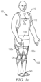
- FIG. 1a shows user 100 wearing potential to kinetic suit (P2K) 102 suitable for human assistance in crouching, squatting, and lifting under load.
- P2K 102 is a passive personal augmentation suit or strapping system, i.e., no active components, applicable to many types of human activity and physical work, such as moving heavy articles, up and down motion under load, and other repetitive, long-term physical exertion.
- P2K 102 is capable of storing potential energy in the strapping arrangement, e.g., potential energy is stored in elastic strapping when transitioning from a standing position to a crouched or squatting position.
- P2K 102 The potential energy in P2K 102 is released when user 100 moves from the crouched or squatting position to return upright in stance, thereby assisting the user in the motion, particularly while under load.
- P2K 102 increases endurance, reduces fatigue, and decreases potential for injury associated with such activity, particularly for the user's back, legs, and knees.
- P2K 102 includes an interconnected arrangement of straps, belts, and braces to provide passively loaded support and reaction for user 100 while assisting with human motion under load.
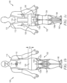
- FIG. 1b shows a front view of P2K 102;
- FIG. 1c shows a back view of P2K 102.
- Upper torso harness 110 includes shoulder straps 112 around the shoulders of user 100, back interconnect strap 114 between shoulder straps 112, front strap 116 with adjustable buckle 118.
- Back interconnect strap 114 and front strap 116 are affixed to shoulder straps 112 with sewing, rivets, buckles, buttons, adhesive, Velcro, or other secure attachment mechanism.
- Shoulder straps 112 extend down the back of user 100 to waist and back belt 120.
- Waist and back belt 120 wraps around the waist, hips, and lower back area and secures with Velcro or buckles.
- belt 120 has a width W1 of 7-18 centimeters (cm).
- Shoulder straps 112 can slide within upper torso harness 1160 and are affixed to belt 120 with sewing, rivets, buckles, buttons, adhesive, Velcro, or other secure attachment mechanism. Waist and back belt 120 provides a brace to support the lower back and tightens to squeeze the hips when squatting.
- Thigh straps 130 extend from waist and back belt 120 over the gluteal area and around the thigh area of user 100. Thigh straps 130 connect to belt 120 with sewing, rivets, buckles, buttons, adhesive, Velcro, or other secure attachment mechanism.
- thigh straps 130 include Y-configured strap 132a over the gluteal area and hamstrings, side straps 132b, and front straps 132c over the quadriceps.
- Knee support 134 connects to Y-configured strap 132a and side straps 132b with sewing, rivets, buckles, buttons, adhesive, Velcro, or other secure attachment mechanism. Knee support 134 includes a pocket or cavity for the knee of user 100, with support material covering the knee and straps around the knee.
- Knee support 134 and side straps 132b can include pads to provide hard support points for P2K 102.
- Calf straps 138 connect to knee support 134 with sewing, rivets, buckles, buttons, adhesive, Velcro, or other secure attachment mechanism.
- calf straps 138 include Y-configured strap 138a over the calf of user 100.
- Foot anchor 140 connects to calf strap 138 with sewing, rivets, buckles, buttons, adhesive, Velcro, or other secure attachment mechanism.
- Foot anchor 140 is configured to connect to a shoe, boot, or directly to the foot, e.g., under and over the foot with an adhesive or sock-like slip-on.
- P2K 102 is modular in construction, configuration, and use. P2K 102 can be configured with various combinations of components described in FIGs. 1a-1c .
- P2K 102 can be used as waist and back belt 120 with thigh straps 130, knee support 138, calf straps 138, and foot anchor 140, without shoulder straps 112. Configurations with shoulder straps 112 have the advantage of encouraging good posture.
- the various straps and belts in FIGs. 1a-1c can be implemented using fabric or leather material, elastic bands, cables, or other suitable flexible connecting members. Springs, pulleys, guides, and other compliant members can be used in place of or to augment the straps and belts within P2K 102.
- P2K 102 is adjustable for size and pre-tensioning the elastic components.
- P2K 102 stores potential energy in the strapping arrangement, e.g., the elastic strapping stretches and stores potential energy when transitioning from a standing position to a crouched, squatting, or seated position.
- the potential energy in P2K 102 remains available while user 100 is seated to help with the opposing motion, i.e., standing up under load.
- Waist and back belt 120 provides a brace to support the lower back and tightens to squeeze the hips when sitting.
- User 100 stands up from the seated position with load 144, as shown in FIG. 2b .
- knee support 134 includes a torsional spring to aid with transition from a seated, kneeling, or squatting position to a standing position, without the use of active components.
- knee support 134 uses elastic bands, or a combination of non-elastic and elastic bands, to assist user 100 in the sit to stand transition.
- P2K 102 utilizes a flexible, modular, passive strapping system that, in one embodiment, extends from upper torso harness 110 to waist and back belt 120 and further travels down gluteal area and hamstrings with thigh straps 130 to knee support 134. P2K 102 can further extend from knee support 134 over the calf area with calf straps 138 to foot anchor 140. P2K 102 gains support from upper torso harness 110 and belt 120, as well as the strapping arrangement from the back of the thigh, front of the knee, and back of the tibia to anchor at the foot.
- the strapping arrangement stores energy in the elastic bands or springs during the squatting or crouching motion to be released during transition to the standing position thus assisting with human motion under load.
- the crossed straps also hold P2K 102 in place during various movements, such as squatting.
- Elastic bands have been found to be particularly effective in areas 146 and 148 (belt 120), area 150 (thigh straps 130), and area 152 (calf straps 138) for assisting with human motion under load, as shown in FIGs. 3a-3b .
- Elastic bands in areas 146-152 can vary in elasticity and stiffness with any preloading adjustable for the user 100 during the fitting process.
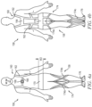
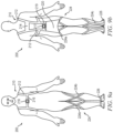
- FIGs. 4a-4b illustrate another embodiment of user 156 wearing P2K 158 suitable for human assistance in crouching, squatting, and lifting under load.
- FIG. 4a shows a front view of P2K 158;
- FIG. 4b shows a back view of P2K 158.
- P2K 158 is a passive personal augmentation suit or strapping system, i.e., no active components, applicable to many types of human activity and physical work, such as moving heavy articles, up and down motion under load, and other repetitive, long-term physical exertion.
- P2K 158 is capable of storing potential energy in the strapping arrangement, e.g., potential energy is stored in elastic strapping when transitioning from a standing position to a crouched or squatting position.
- P2K 158 The potential energy in P2K 158 is released when user 156 moves from the crouched or squatting position to return upright in stance, thereby assisting the user in the motion, particularly while under load.
- P2K 158 increases endurance, reduces fatigue, and decreases potential for injury associated with such activity, particularly for the user's back, legs, and knees.
- P2K 158 includes an interconnected arrangement of straps, belts, and braces to provide passively loaded support and reaction for user 156 while assisting with human motion under load.
- Upper torso harness 160 includes shoulder straps 162 around the shoulders of user 156, back interconnect strap 164 between shoulder straps 162, front strap 166 with adjustable buckle 168.
- Back interconnect strap 164 and front strap 166 are affixed to shoulder straps 162 with sewing, rivets, buckles, buttons, adhesive, Velcro, or other secure attachment mechanism.
- Shoulder straps 162 extend down the back to waist and back belt 170.
- Waist and back belt 170 wraps around the waist, hips, and lower back area and secures with Velcro or buckles.
- belt 170 has a width W2 of 7-18 cm.
- Shoulder straps 162 can slide within upper torso harness 160 and are affixed to belt 170 with sewing, rivets, buckles, buttons, adhesive, Velcro, or other secure attachment mechanism. Waist and back belt 170 provides a brace to support the lower back and tightens to squeeze the hips when squatting.
- Leg strap arrangement 174 extends down the legs of user 156.
- Leg straps 174 include Y-configured thigh portion 174a over the gluteal area and hamstrings of user 156, cross-configured knee portion 174b over the front of the knee area, and Y-configured calf portion 174c over the calf area.
- Thigh portion 174a connect to waist and back belt 170 with sewing, rivets, buckles, buttons, adhesive, Velcro, or other secure attachment mechanism.
- Leg straps 174 utilize the bending motion of the ankle and knee for maximum stretching of the elastic bands.
- Foot anchor 176 connects to calf portion 174c behind the heel with sewing, rivets, buckles, buttons, adhesive, Velcro, or other secure attachment mechanism.
- Foot anchor 176 connects to a shoe, boot, or directly to the foot, e.g., under and over the foot with an adhesive or sock-like slip-on.
- P2K 158 is modular in construction, configuration, and use.
- P2K 158 can be used as waist and back belt 170 with leg straps 174, without shoulder straps 162.
- the various straps and belts in FIGs. 4a-4b can be implemented using fabric or leather material, elastic bands, cables, or other suitable flexible connecting members.
- P2K 158 stores potential energy in the strapping arrangement, e.g., potential energy is stored in elastic strapping when transitioning from a standing position to a crouched, squatting, or seated position.
- the potential energy in P2K 158 is released when user 156 moves from the crouched, squatting, or seated position to return upright in stance, thereby assisting the user in the motion, particularly while under load.
- P2K 158 is adjustable for size and pre-tensioning the elastic components.
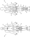
- FIGs. 5a-5b illustrate a modified P2K 158, similar to FIGs. 4a-4b , with front torso cross straps 178 for additional support.
- FIGs. 6a-6b illustrate a modified P2K 158, similar to FIGs. 4a-4b , with buckles 180 and 182 for adjustment and attachment points on the front of P2K 158, and buckles 184 for adjustment and attachment points on the back of P2K 158.
- FIG. 7 shows further detail of leg straps 174 from waist and back belt 170 to foot anchor 176.
- Leg straps 174 can be made with elastic bands crossing at knee portion 174b, i.e., in front of the knee.
- Leg straps 174 can include buckles 188 or Velcro for ease of donning and doffing P2K 158.
- the user's foot slides over heel strap 176a and into arch wrap 176b to fix leg straps 174 in place.
- Foot anchor 176 can be attached over a shoe.
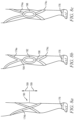
- FIG. 8a shows leg straps 174 crossing in front of knee 190.
- Leg straps can be positioned to cross above, directly on, or below the knee cap, as shown by the range of arrows 189.
- FIG. 8b shows leg straps 174 crossing above and below the knee with pocket 192 around the knee cap for comfort and stability.
- a first single strap 194 extends above pocket 192 to thigh portion 174a.
- a second single strap 196 extends below pocket 192 to calf portion 174c.
- FIG. 8c shows leg straps 174 crossing in front of the knee with pocket 198 around the knee cap for comfort and stability.
- Thigh portion 174a connects to an upper point of pocket 198
- calf portion 174c connects to a lower point of pocket 198.
- FIGs. 9a-9b illustrate another embodiment of user 200 wearing P2K 202 suitable for human assistance in crouching, squatting, and lifting under load.
- FIG. 9a shows a front view of P2K 202;
- FIG. 9b shows a back view of P2K 202.
- P2K 202 is a passive personal augmentation suit or strapping system, i.e., no active components, applicable to many types of human activity and physical work, such as moving heavy articles, up and down motion under load, and other repetitive, long-term physical exertion.
- P2K 202 is capable of storing potential energy in the strapping arrangement, e.g., potential energy is stored in elastic strapping when transitioning from a standing position to a crouched or squatting position.
- P2K 202 The potential energy in P2K 202 is released when user 200 moves from the crouched or squatting position to return upright in stance, thereby assisting the user in the motion, particularly while under load.
- P2K 202 increases endurance, reduces fatigue, and decreases potential for injury associated with such activity, particularly for the user's back, legs, and knees.
- P2K 202 includes an interconnected arrangement of straps, belts, and braces to provide passively loaded support and reaction for user 200 while assisting with human motion under load.
- Upper torso harness 210 includes shoulder straps 212 around the shoulders of user 200, upper back interconnect strap 214 between shoulder straps 212, front strap 216 with adjustable buckle 218.
- Back interconnect strap 214 and front strap 216 are affixed to shoulder straps 212 with sewing, rivets, buckles, buttons, adhesive, Velcro, or other secure attachment mechanism.
- Shoulder straps 162 extend down the back to back support 220 and affix with sewing, rivets, buckles, buttons, adhesive, Velcro, or other secure attachment mechanism.
- Lower back interconnect strap 219 is connected above back support 220.
- Leg strap arrangement 224 extends down the legs of user 200.
- Leg straps 224 include Y-configured thigh portion 224a over the gluteal area and hamstrings of user 200, cross-configured knee portion 224b over the front of the knee area, and Y-configured calf portion 224c over the calf area.
- Thigh portion 224a connects to back support 220 with sewing, rivets, buckles, buttons, adhesive, Velcro, or other secure attachment mechanism.
- Leg straps 224 utilize the bending motion of the ankle and knee for maximum stretching of the elastic bands.
- Foot anchor 226 connects to calf portion 224c behind the heel with sewing, rivets, buckles, buttons, adhesive, Velcro, or other secure attachment mechanism.
- Foot anchor 226 connect to a shoe, boot, or directly to the foot, e.g., under and over the foot with an adhesive or sock-like slip-on.
- P2K 202 stores potential energy in the strapping arrangement, e.g., potential energy is stored in elastic strapping when transitioning from a standing position to a crouched, squatting, or seated position.
- the potential energy in P2K 202 is released when user 200 moves from the crouched, squatting, or seated position to return upright in stance, thereby assisting the user in the motion, particularly while under load.
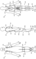
- FIGs. 10a-10c illustrate another embodiment of user 230 wearing P2K 232 suitable for human assistance in crouching, squatting, and lifting under load.
- FIG. 10a shows a front view of P2K 232;
- FIG. 10b shows a side view of P2K 232;
- FIG. 10c shows a back view of P2K 232.
- P2K 232 is a passive personal augmentation suit or strapping system, i.e., no active components, applicable to many types of human activity and physical work, such as moving heavy articles, up and down motion under load, and other repetitive, long-term physical exertion.
- P2K 232 is capable of storing potential energy in the strapping arrangement, e.g., potential energy is stored in elastic strapping when transitioning from a standing position to a crouched or squatting position.
- the potential energy in P2K 232 is released when user 230 moves from the crouched or squatting position to return upright in stance, thereby assisting the user in the motion, particularly while under load.
- P2K 232 increases endurance, reduces fatigue, and decreases potential for injury associated with such activity, particularly for the user's back, legs, and knees.
- P2K 232 includes an interconnected arrangement of straps, belts, and braces to provide passively loaded support and reaction for user 230 while assisting with human motion under load. Portions of P2K 232 can be reflective material for safety.
- Upper torso harness 240 includes backpack assembly 242 with shoulder straps 244.
- Backpack assembly 242 can be made with an air mesh material with openings to allow for air-flow on the back and reduces the overall weight.
- Backpack assembly 242 can include a combination of elastic material and webbing material.
- Backpack assembly 242 covers a portion of back area of user 230 to improve ergonomics and comfort, relieve lower back pressure, and ease of donning and doffing.
- Shoulder straps 244 extend over the shoulder and affix to backpack assembly 242 with sewing, rivets, buckles, buttons, adhesive, Velcro, or other secure attachment mechanism. Shoulder straps 244 can slide relative to backpack assembly 242 for user comfort.
- Buckles 246 in shoulder straps 244 provide adjustment and attachment points.
- Buckles 246 can be used to adjust elastic pre-load (strength of the suit when squatting down) and enable P2K 232 to fit different body sizes.
- Back support 250 connects to backpack assembly 242 with sewing, rivets, buckles, buttons, adhesive, Velcro, or other secure attachment mechanism.
- Side straps 252 extend from shoulder straps 244 to back support 250.
- Side straps 252 can include elastic material with buckles for adjustments and comfort, see FIG. 11a .
- Back support 250 slides or moves relative to backpack assembly 242 to minimize medial/lateral relative motion and provide pre-tensioning.
- Leg strap arrangement 258 extends down the legs of user 230.
- Leg straps 258 include thigh portion 258a over the gluteal area and hamstrings of user 230, knee portion 258b over the front of the knee area, and calf portion 258c over the calf area.
- Thigh portion 258a connects to back support 250 with sewing, rivets, buckles, buttons, adhesive, Velcro, or other secure attachment mechanism.
- Seat webbing 254 is connected to back support 250 and thigh portion 258a with sewing, rivets, buckles, buttons, adhesive, Velcro, or other secure attachment mechanism.
- Seat webbing 254 is an elastic material for storing and releasing power and comfortable load distribution.
- Knee portion 258b includes a knee pad for knee protection while kneeling on the ground.
- Foot anchor 260 utilizes bending motion of the ankle and knee for maximum stretching of the elastic bands.
- Foot anchor 260 connects to calf portion 258c behind the heel with sewing, rivets, buckles, buttons, adhesive, Velcro, or other secure attachment mechanism. Foot anchor 260 crosses over the talus and then wraps around the arch. Foot anchor 260 can be configured to connect to a shoe, boot, or directly to the foot.
- P2K 232 stores potential energy in the strapping arrangement, e.g., the elastic strapping stretches and stores potential energy when transitioning from a standing position to a crouched, squatting, or seated position.
- the potential energy in P2K 232 remains available while user 230 is seated to help with the opposing motion, i.e., standing up under load.
- the potential energy in P2K 232 is released to assist the user in the motion.
- P2K 232 reduces the effort, strain, fatigue, and potential for injury associated such movement in physical labor work environments.
- FIGs. 11a-11c illustrate another embodiment of user 230 wearing P2K 232 with buckles 270 in side straps 252.
- Buckles 270 in combination with elastic material in side straps 252 provide further adjustments, support, and comfort for user 230 in donning, doffing, and wearing upper torso harness 240 and backpack assembly 242.
- Side straps 252 with buckles 250 keep back support 250 and seat webbing 254 in place during motion, e.g. while walking.
- Knee portion 258b includes connection point 272 to connect and separate a left half of the knee pad and a right half of the knee pad, which aids with donning and doffing leg strap arrangement 258.
- connection point 272 can be Velcro, buckles, buttons, or other removable attachment mechanism.
Landscapes
- Health & Medical Sciences (AREA)
- Engineering & Computer Science (AREA)
- General Health & Medical Sciences (AREA)
- Pain & Pain Management (AREA)
- Rehabilitation Therapy (AREA)
- Robotics (AREA)
- Mechanical Engineering (AREA)
- Epidemiology (AREA)
- Veterinary Medicine (AREA)
- Physical Education & Sports Medicine (AREA)
- Public Health (AREA)
- Life Sciences & Earth Sciences (AREA)
- Animal Behavior & Ethology (AREA)
- Rheumatology (AREA)
- Orthopedic Medicine & Surgery (AREA)
- Professional, Industrial, Or Sporting Protective Garments (AREA)
- Orthopedics, Nursing, And Contraception (AREA)
- Manipulator (AREA)
- Rehabilitation Tools (AREA)
Description
- The present invention relates in general to a human assistance device, and more particularly, to a personal augmentation suit and method for assisted human motion.
- A variety of human assistance devices provide aid for human motion. Some work tasks and activities demand frequent and heavy lifting or long-term strenuous movement, beyond normal unassisted physical exertion, and can lead to exhaustion and potential injury. In particular, excessive strain on muscles and joints can cause injury to the back, legs, and knees with associated reduction in productivity. The human assistance device as worn by the user is designed to overcome or compensate for the added load or strain and make many work tasks easier to perform.
- In one embodiment, the human assistance device uses an exoskeleton with rigid components e.g., linkages and joints, attached to the user's body. The exoskeleton joints are ideally positioned to have an axis of rotation collinear with a natural axis of rotation for adjacent joints. The rigid exoskeleton relies on a framework of linkages connected to the body at select locations via pads and straps to provide the ability to augment human movements that need assistance or otherwise enhance the user's performance, stability, balance, and safety. As the user flexes or extends their limbs, these rigid links move in parallel with the limb, adding considerable inertia to movement. Unfortunately, the rigid exoskeleton also causes considerable restriction to the user's motion that impedes natural and fluid movement.
- In another example,
U.S. patent publication 2015/0321339 discloses a soft exosuit that generates forces about one or more joints based on anchor elements and connection elements disposed between the anchor elements. The exosuit uses sensors to determine forces on the anchor or connection elements. Actuators are configured to change tension in the soft exosuit in response to the sensors. The exosuit tends to be complex with an overreliance on active components, such as sensors and actuators, to control its operation. The intricate interconnection of anchor elements, connection elements, sensors, and actuators tends to be expensive to manufacture, difficult to configure, slow in response, and overall low reliability.
US 2010/125230 A1 discloses a back support system designed to reduce the stress exerted on the back of a wearer when he bends over to lift a load. The back support system comprises a harness and a yoke for distributing the load on the shoulder of the wearer. The back support comprises a tension system equipped with elastic cables. The back support comprises leggings including straps designed to wrap around the sole of the wearer and to maintain the force acting on the leg as close as possible to the bone structure of the leg of the wearer.
US 4,813,080 discloses a device for supporting the lower back region of a person combined with an upper torso garment. A pair of elongated straps are integrally attached to a support pad and extend from the sides of a back panel to form a pair of loops. Each strap may also include knee pads which are adjustably positioned along the length of each of the straps using a suitable support means. A user can secure the straps to lower anchor straps thereby forming loops which engage the knees of the wearer. With a wearer seated on a flat ground surface and with his knees up in the air, the upper support position is more effective in providing increased support and comfort to the user.
US 5,716,307 discloses a body exercise device that includes, among others, a right knee engaging apparatus for selectively maintaining the right member against the right knee of the exerciser. A right side member knee maintaining apparatus elastic sleeve anterior portion of a right side member knee maintaining apparatus elastic sleeve of the right side member knee maintaining apparatus of the right side member has a right side member knee maintaining apparatus elastic sleeve anterior portion flap disposed over most of the right side member knee maintaining apparatus elastic sleeve anterior portion and provides additional cushioning similar to that of a knee pad.
US 7,744,511 B2 discloses a device for training sportsmen or physical workout of long-time bed patient. The device comprises a shoulder pad, breast pad, pelvis pad designed as shorts, knee pads performed as bandages and foot pads, all connected together by means of a loading elements with a possibility of being disconnected.
US 5,993,362 discloses an exercise device for martial arts conditioning including a belt having rings, a torso harness a hand stirrup for each hand, a knee band for each knee, and an ankle band for each ankle. The knee band includes base pad which is worn against the knee. The knee band aligns the cords in proper placement around the knee to provide guidance and resistance in both the recoil and forward motions to the leg muscles used in kicking. - It is therefore the object of the present invention to provide an improved human assistance device attachable to a user and comprising a leg strap arrangement, as well as a corresponding method of making a human assistance device.
- This object is solved by the subject matter of the independent claims.
- Preferred embodiments are defined by the dependent claims.
-
-
FIGs. 1a-1c illustrate a user wearing a passive P2K suit; -
FIGs. 2a-2b illustrate the user transitioning from a seated position to standing position with aid from the passive P2K suit; -
FIGs. 3a-3b illustrate elastic bands in the passive P2K suit; -
FIGs. 4a-4b illustrate a second embodiment of the passive P2K suit with elastic leg straps; -
FIGs. 5a-5b illustrate a third embodiment of the passive P2K suit with front torso cross straps; -
FIGs. 6a-6b illustrate a fourth embodiment of the passive P2K suit with buckles to adjust the upper torso harness; -
FIG. 7 illustrates further detail of the leg straps and foot anchor; -
FIGs. 8a-8c illustrate further detail of the leg straps and foot anchor; -
FIGs. 9a-9b illustrate a fifth embodiment of the passive P2K suit with back support, wherein the example embodiments shown in thefigures 1a-9b are not covered by the claims. -
FIGs. 10a-10c illustrate a sixth embodiment of the passive P2K suit with a backpack assembly; and -
FIGs. 11a-11c illustrate a seventh embodiment of the passive P2K suit with a backpack assembly and split knee pad. - The present invention is described in one or more embodiments in the following description with reference to the figures, in which like numerals represent the same or similar elements.
-
FIG. 1a showsuser 100 wearing potential to kinetic suit (P2K) 102 suitable for human assistance in crouching, squatting, and lifting under load.P2K 102 is a passive personal augmentation suit or strapping system, i.e., no active components, applicable to many types of human activity and physical work, such as moving heavy articles, up and down motion under load, and other repetitive, long-term physical exertion.P2K 102 is capable of storing potential energy in the strapping arrangement, e.g., potential energy is stored in elastic strapping when transitioning from a standing position to a crouched or squatting position. The potential energy inP2K 102 is released whenuser 100 moves from the crouched or squatting position to return upright in stance, thereby assisting the user in the motion, particularly while under load.P2K 102 increases endurance, reduces fatigue, and decreases potential for injury associated with such activity, particularly for the user's back, legs, and knees.P2K 102 includes an interconnected arrangement of straps, belts, and braces to provide passively loaded support and reaction foruser 100 while assisting with human motion under load.FIG. 1b shows a front view ofP2K 102;FIG. 1c shows a back view ofP2K 102. -
Upper torso harness 110 includesshoulder straps 112 around the shoulders ofuser 100, backinterconnect strap 114 betweenshoulder straps 112,front strap 116 withadjustable buckle 118. Backinterconnect strap 114 andfront strap 116 are affixed toshoulder straps 112 with sewing, rivets, buckles, buttons, adhesive, Velcro, or other secure attachment mechanism.Shoulder straps 112 extend down the back ofuser 100 to waist andback belt 120. Waist andback belt 120 wraps around the waist, hips, and lower back area and secures with Velcro or buckles. In one embodiment,belt 120 has a width W1 of 7-18 centimeters (cm).Shoulder straps 112 can slide within upper torso harness 1160 and are affixed to belt 120 with sewing, rivets, buckles, buttons, adhesive, Velcro, or other secure attachment mechanism. Waist andback belt 120 provides a brace to support the lower back and tightens to squeeze the hips when squatting. - Thigh straps 130 extend from waist and
back belt 120 over the gluteal area and around the thigh area ofuser 100. Thigh straps 130 connect to belt 120 with sewing, rivets, buckles, buttons, adhesive, Velcro, or other secure attachment mechanism. In particular, thigh straps 130 include Y-configuredstrap 132a over the gluteal area and hamstrings, side straps 132b, andfront straps 132c over the quadriceps.Knee support 134 connects to Y-configuredstrap 132a and side straps 132b with sewing, rivets, buckles, buttons, adhesive, Velcro, or other secure attachment mechanism.Knee support 134 includes a pocket or cavity for the knee ofuser 100, with support material covering the knee and straps around the knee.Knee support 134 andside straps 132b can include pads to provide hard support points forP2K 102. Calf straps 138 connect toknee support 134 with sewing, rivets, buckles, buttons, adhesive, Velcro, or other secure attachment mechanism. In particular, calf straps 138 include Y-configuredstrap 138a over the calf ofuser 100.Foot anchor 140 connects tocalf strap 138 with sewing, rivets, buckles, buttons, adhesive, Velcro, or other secure attachment mechanism.Foot anchor 140 is configured to connect to a shoe, boot, or directly to the foot, e.g., under and over the foot with an adhesive or sock-like slip-on. -
P2K 102 is modular in construction, configuration, and use.P2K 102 can be configured with various combinations of components described inFIGs. 1a-1c . For example,P2K 102 can be used as waist andback belt 120 withthigh straps 130,knee support 138, calf straps 138, andfoot anchor 140, without shoulder straps 112. Configurations withshoulder straps 112 have the advantage of encouraging good posture. The various straps and belts inFIGs. 1a-1c can be implemented using fabric or leather material, elastic bands, cables, or other suitable flexible connecting members. Springs, pulleys, guides, and other compliant members can be used in place of or to augment the straps and belts withinP2K 102.P2K 102 is adjustable for size and pre-tensioning the elastic components. - Consider
user 100 wearingP2K 102 in the seated position onseat 142 and holdingload 144 inFIG. 2a .P2K 102 stores potential energy in the strapping arrangement, e.g., the elastic strapping stretches and stores potential energy when transitioning from a standing position to a crouched, squatting, or seated position. The potential energy inP2K 102 remains available whileuser 100 is seated to help with the opposing motion, i.e., standing up under load. Waist andback belt 120 provides a brace to support the lower back and tightens to squeeze the hips when sitting.User 100 stands up from the seated position withload 144, as shown inFIG. 2b . The potential energy inP2K 102 is released whenuser 100 moves from the crouched, squatting, or seated position to return upright in stance, thereby assisting the user in the motion, particularly while under load.P2K 102 reduces the effort, strain, fatigue, and potential for injury associated such movement in physical labor work environments. A similar concept applies touser 100 standing from the kneeling or crouching position. In one embodiment,knee support 134 includes a torsional spring to aid with transition from a seated, kneeling, or squatting position to a standing position, without the use of active components. Alternatively,knee support 134 uses elastic bands, or a combination of non-elastic and elastic bands, to assistuser 100 in the sit to stand transition. - In general,
P2K 102 utilizes a flexible, modular, passive strapping system that, in one embodiment, extends fromupper torso harness 110 to waist andback belt 120 and further travels down gluteal area and hamstrings withthigh straps 130 toknee support 134.P2K 102 can further extend fromknee support 134 over the calf area withcalf straps 138 tofoot anchor 140.P2K 102 gains support fromupper torso harness 110 andbelt 120, as well as the strapping arrangement from the back of the thigh, front of the knee, and back of the tibia to anchor at the foot. Because the straps cross at the waist and over the length of the leg, the strapping arrangement stores energy in the elastic bands or springs during the squatting or crouching motion to be released during transition to the standing position thus assisting with human motion under load. The crossed straps also holdP2K 102 in place during various movements, such as squatting. - Elastic bands have been found to be particularly effective in
areas 146 and 148 (belt 120), area 150 (thigh straps 130), and area 152 (calf straps 138) for assisting with human motion under load, as shown inFIGs. 3a-3b . Elastic bands in areas 146-152 can vary in elasticity and stiffness with any preloading adjustable for theuser 100 during the fitting process. -
FIGs. 4a-4b illustrate another embodiment ofuser 156 wearingP2K 158 suitable for human assistance in crouching, squatting, and lifting under load.FIG. 4a shows a front view ofP2K 158;FIG. 4b shows a back view ofP2K 158.P2K 158 is a passive personal augmentation suit or strapping system, i.e., no active components, applicable to many types of human activity and physical work, such as moving heavy articles, up and down motion under load, and other repetitive, long-term physical exertion.P2K 158 is capable of storing potential energy in the strapping arrangement, e.g., potential energy is stored in elastic strapping when transitioning from a standing position to a crouched or squatting position. The potential energy inP2K 158 is released whenuser 156 moves from the crouched or squatting position to return upright in stance, thereby assisting the user in the motion, particularly while under load.P2K 158 increases endurance, reduces fatigue, and decreases potential for injury associated with such activity, particularly for the user's back, legs, and knees.P2K 158 includes an interconnected arrangement of straps, belts, and braces to provide passively loaded support and reaction foruser 156 while assisting with human motion under load. -
Upper torso harness 160 includesshoulder straps 162 around the shoulders ofuser 156, backinterconnect strap 164 betweenshoulder straps 162,front strap 166 withadjustable buckle 168. Backinterconnect strap 164 andfront strap 166 are affixed toshoulder straps 162 with sewing, rivets, buckles, buttons, adhesive, Velcro, or other secure attachment mechanism.Shoulder straps 162 extend down the back to waist andback belt 170. Waist andback belt 170 wraps around the waist, hips, and lower back area and secures with Velcro or buckles. In one embodiment,belt 170 has a width W2 of 7-18 cm.Shoulder straps 162 can slide withinupper torso harness 160 and are affixed to belt 170 with sewing, rivets, buckles, buttons, adhesive, Velcro, or other secure attachment mechanism. Waist andback belt 170 provides a brace to support the lower back and tightens to squeeze the hips when squatting. -
Leg strap arrangement 174 extends down the legs ofuser 156. Leg straps 174 include Y-configuredthigh portion 174a over the gluteal area and hamstrings ofuser 156,cross-configured knee portion 174b over the front of the knee area, and Y-configuredcalf portion 174c over the calf area.Thigh portion 174a connect to waist andback belt 170 with sewing, rivets, buckles, buttons, adhesive, Velcro, or other secure attachment mechanism. Leg straps 174 utilize the bending motion of the ankle and knee for maximum stretching of the elastic bands.Foot anchor 176 connects tocalf portion 174c behind the heel with sewing, rivets, buckles, buttons, adhesive, Velcro, or other secure attachment mechanism.Foot anchor 176 connects to a shoe, boot, or directly to the foot, e.g., under and over the foot with an adhesive or sock-like slip-on. -
P2K 158 is modular in construction, configuration, and use. For example,P2K 158 can be used as waist andback belt 170 withleg straps 174, without shoulder straps 162. The various straps and belts inFIGs. 4a-4b can be implemented using fabric or leather material, elastic bands, cables, or other suitable flexible connecting members.P2K 158 stores potential energy in the strapping arrangement, e.g., potential energy is stored in elastic strapping when transitioning from a standing position to a crouched, squatting, or seated position. The potential energy inP2K 158 is released whenuser 156 moves from the crouched, squatting, or seated position to return upright in stance, thereby assisting the user in the motion, particularly while under load.P2K 158 is adjustable for size and pre-tensioning the elastic components. -
FIGs. 5a-5b illustrate a modifiedP2K 158, similar toFIGs. 4a-4b , with front torso cross straps 178 for additional support. -
FIGs. 6a-6b illustrate a modifiedP2K 158, similar toFIGs. 4a-4b , withbuckles P2K 158, and buckles 184 for adjustment and attachment points on the back ofP2K 158. -
FIG. 7 shows further detail ofleg straps 174 from waist andback belt 170 tofoot anchor 176. Leg straps 174 can be made with elastic bands crossing atknee portion 174b, i.e., in front of the knee. Leg straps 174 can includebuckles 188 or Velcro for ease of donning and doffingP2K 158. The user's foot slides overheel strap 176a and intoarch wrap 176b to fix leg straps 174 in place.Foot anchor 176 can be attached over a shoe. -
FIG. 8a shows leg straps 174 crossing in front ofknee 190. Leg straps can be positioned to cross above, directly on, or below the knee cap, as shown by the range ofarrows 189.FIG. 8b shows leg straps 174 crossing above and below the knee withpocket 192 around the knee cap for comfort and stability. A firstsingle strap 194 extends abovepocket 192 tothigh portion 174a. A secondsingle strap 196 extends belowpocket 192 tocalf portion 174c.FIG. 8c shows leg straps 174 crossing in front of the knee withpocket 198 around the knee cap for comfort and stability.Thigh portion 174a connects to an upper point ofpocket 198, andcalf portion 174c connects to a lower point ofpocket 198. -
FIGs. 9a-9b illustrate another embodiment ofuser 200 wearing P2K 202 suitable for human assistance in crouching, squatting, and lifting under load.FIG. 9a shows a front view of P2K 202;FIG. 9b shows a back view of P2K 202. P2K 202 is a passive personal augmentation suit or strapping system, i.e., no active components, applicable to many types of human activity and physical work, such as moving heavy articles, up and down motion under load, and other repetitive, long-term physical exertion. P2K 202 is capable of storing potential energy in the strapping arrangement, e.g., potential energy is stored in elastic strapping when transitioning from a standing position to a crouched or squatting position. The potential energy in P2K 202 is released whenuser 200 moves from the crouched or squatting position to return upright in stance, thereby assisting the user in the motion, particularly while under load. P2K 202 increases endurance, reduces fatigue, and decreases potential for injury associated with such activity, particularly for the user's back, legs, and knees. P2K 202 includes an interconnected arrangement of straps, belts, and braces to provide passively loaded support and reaction foruser 200 while assisting with human motion under load. -
Upper torso harness 210 includesshoulder straps 212 around the shoulders ofuser 200, upperback interconnect strap 214 betweenshoulder straps 212,front strap 216 withadjustable buckle 218. Backinterconnect strap 214 andfront strap 216 are affixed toshoulder straps 212 with sewing, rivets, buckles, buttons, adhesive, Velcro, or other secure attachment mechanism.Shoulder straps 162 extend down the back toback support 220 and affix with sewing, rivets, buckles, buttons, adhesive, Velcro, or other secure attachment mechanism. Lower backinterconnect strap 219 is connected aboveback support 220. -
Leg strap arrangement 224 extends down the legs ofuser 200. Leg straps 224 include Y-configuredthigh portion 224a over the gluteal area and hamstrings ofuser 200,cross-configured knee portion 224b over the front of the knee area, and Y-configuredcalf portion 224c over the calf area.Thigh portion 224a connects to backsupport 220 with sewing, rivets, buckles, buttons, adhesive, Velcro, or other secure attachment mechanism. Leg straps 224 utilize the bending motion of the ankle and knee for maximum stretching of the elastic bands.Foot anchor 226 connects tocalf portion 224c behind the heel with sewing, rivets, buckles, buttons, adhesive, Velcro, or other secure attachment mechanism.Foot anchor 226 connect to a shoe, boot, or directly to the foot, e.g., under and over the foot with an adhesive or sock-like slip-on. - P2K 202 stores potential energy in the strapping arrangement, e.g., potential energy is stored in elastic strapping when transitioning from a standing position to a crouched, squatting, or seated position. The potential energy in P2K 202 is released when
user 200 moves from the crouched, squatting, or seated position to return upright in stance, thereby assisting the user in the motion, particularly while under load. -
FIGs. 10a-10c illustrate another embodiment ofuser 230 wearingP2K 232 suitable for human assistance in crouching, squatting, and lifting under load.FIG. 10a shows a front view ofP2K 232;FIG. 10b shows a side view ofP2K 232;FIG. 10c shows a back view ofP2K 232.P2K 232 is a passive personal augmentation suit or strapping system, i.e., no active components, applicable to many types of human activity and physical work, such as moving heavy articles, up and down motion under load, and other repetitive, long-term physical exertion.P2K 232 is capable of storing potential energy in the strapping arrangement, e.g., potential energy is stored in elastic strapping when transitioning from a standing position to a crouched or squatting position. The potential energy inP2K 232 is released whenuser 230 moves from the crouched or squatting position to return upright in stance, thereby assisting the user in the motion, particularly while under load.P2K 232 increases endurance, reduces fatigue, and decreases potential for injury associated with such activity, particularly for the user's back, legs, and knees.P2K 232 includes an interconnected arrangement of straps, belts, and braces to provide passively loaded support and reaction foruser 230 while assisting with human motion under load. Portions ofP2K 232 can be reflective material for safety. -
Upper torso harness 240 includesbackpack assembly 242 withshoulder straps 244.Backpack assembly 242 can be made with an air mesh material with openings to allow for air-flow on the back and reduces the overall weight.Backpack assembly 242 can include a combination of elastic material and webbing material.Backpack assembly 242 covers a portion of back area ofuser 230 to improve ergonomics and comfort, relieve lower back pressure, and ease of donning and doffing.Shoulder straps 244 extend over the shoulder and affix tobackpack assembly 242 with sewing, rivets, buckles, buttons, adhesive, Velcro, or other secure attachment mechanism.Shoulder straps 244 can slide relative tobackpack assembly 242 for user comfort.Buckles 246 inshoulder straps 244 provide adjustment and attachment points.Buckles 246 can be used to adjust elastic pre-load (strength of the suit when squatting down) and enableP2K 232 to fit different body sizes.Back support 250 connects tobackpack assembly 242 with sewing, rivets, buckles, buttons, adhesive, Velcro, or other secure attachment mechanism. Side straps 252 extend fromshoulder straps 244 to backsupport 250. Side straps 252 can include elastic material with buckles for adjustments and comfort, seeFIG. 11a .Back support 250 slides or moves relative tobackpack assembly 242 to minimize medial/lateral relative motion and provide pre-tensioning. -
Leg strap arrangement 258 extends down the legs ofuser 230. Leg straps 258 includethigh portion 258a over the gluteal area and hamstrings ofuser 230,knee portion 258b over the front of the knee area, andcalf portion 258c over the calf area.Thigh portion 258a connects to backsupport 250 with sewing, rivets, buckles, buttons, adhesive, Velcro, or other secure attachment mechanism.Seat webbing 254 is connected to backsupport 250 andthigh portion 258a with sewing, rivets, buckles, buttons, adhesive, Velcro, or other secure attachment mechanism.Seat webbing 254 is an elastic material for storing and releasing power and comfortable load distribution.Knee portion 258b includes a knee pad for knee protection while kneeling on the ground. Leg straps 258 utilize the bending motion of the ankle and knee for maximum stretching of the elastic bands.Foot anchor 260 connects tocalf portion 258c behind the heel with sewing, rivets, buckles, buttons, adhesive, Velcro, or other secure attachment mechanism.Foot anchor 260 crosses over the talus and then wraps around the arch.Foot anchor 260 can be configured to connect to a shoe, boot, or directly to the foot. - The various straps and belts in
FIGs. 10a-10c can be implemented using fabric or leather material, elastic bands, cables, or other suitable flexible connecting members.P2K 232 stores potential energy in the strapping arrangement, e.g., the elastic strapping stretches and stores potential energy when transitioning from a standing position to a crouched, squatting, or seated position. The potential energy inP2K 232 remains available whileuser 230 is seated to help with the opposing motion, i.e., standing up under load. Whenuser 230 stands up from the seated position under load, similar toFIG. 2b , the potential energy inP2K 232 is released to assist the user in the motion.P2K 232 reduces the effort, strain, fatigue, and potential for injury associated such movement in physical labor work environments. -
FIGs. 11a-11c illustrate another embodiment ofuser 230 wearingP2K 232 withbuckles 270 in side straps 252.Buckles 270 in combination with elastic material inside straps 252 provide further adjustments, support, and comfort foruser 230 in donning, doffing, and wearingupper torso harness 240 andbackpack assembly 242. Side straps 252 withbuckles 250 keep backsupport 250 andseat webbing 254 in place during motion, e.g. while walking.Knee portion 258b includesconnection point 272 to connect and separate a left half of the knee pad and a right half of the knee pad, which aids with donning and doffingleg strap arrangement 258. For example,user 230 brings the left half of the knee pad and the right half of the knee pad together and secures withconnection point 272. To removeleg strap arrangement 258,user 230 detaches the left half of the knee pad from right half of the knee pad atconnection point 272.Connection point 272 can be Velcro, buckles, buttons, or other removable attachment mechanism. - While one or more embodiments of the present invention have been illustrated in detail, the skilled artisan will appreciate that modifications and adaptations to those embodiments may be made without departing from the scope of the present invention as set forth in the following claims.
Claims (8)
- A human assistance device, comprising:an upper torso harness (240) configured to attach to a user (230); anda leg strap arrangement (258) extending down the legs of the user and including a thigh portion (258a) over a gluteal area and the hamstrings of the user, the leg strap arrangement further including a knee portion including a knee pad (258b) over the front of the knee area of the user, and the leg strap arrangement further including a calf portion (258c) over the calf area of the user, wherein the thigh portion is adapted to affix to the upper torso harness proximate to the gluteal area of the user and configured to extend down from the gluteal area over the hamstrings of the user to the knee pad (258b), and wherein the calf portion is configured to extend down from the knee pad over the calf area of the user to a foot anchor (260), wherein the upper torso harness and leg strap arrangement comprise elastic material.
- The human assistance device of claim 1, wherein the knee pad (258b) includes a connection point (272) configured to separate a left half of the knee pad and a right half of the knee pad.
- The human assistance device of claim 1, wherein the upper torso harness (240) includes a backpack assembly (242).
- The human assistance device of claim 1, further including a seat webbing (254) over the gluteal area of the user (230), wherein the seat webbing is connected to a back support (250) of the upper torso harness (240) and to the thigh portion (258a) of the leg strap arrangement (258), and wherein the seat webbing is an elastic material for storing and releasing power and comfortable load distribution.
- A method of making human assistance device, comprising:providing an upper torso harness (240) configured to attach to a user (230); andconnecting a leg strap arrangement (258) to the upper torso harness proximate to a gluteal area of the user, wherein the leg strap arrangement extends down the legs of the user and includes a thigh portion (258a) over the gluteal area and the hamstrings of the user, the leg strap arrangement further includes a knee portion including a knee pad (258b) over the front of the knee area of the user, and the leg strap arrangement further includes a calf portion (258c) over the calf area of the user, wherein the thigh portion is configured to extend down from the gluteal area over the hamstrings of the user to the knee pad (258b) and wherein the calf portion is configured to extend down from the knee pad over the calf area of the user to a foot anchor (260), wherein the upper torso harness and leg strap arrangement comprise elastic material.
- The method of claim 5, wherein the knee pad (258b) includes a connection point (272) configured to separate a left half of the knee pad and a right half of the knee pad.
- The method of claim 5, wherein the upper torso harness (240) includes a backpack assembly (242).
- The method of claim 5, further including a seat webbing (254) over the gluteal area of the user (230), wherein the seat webbing is connected to a back support (250) of the upper torso harness (240) and to the thigh portion (258a) of the leg strap arrangement (258), and wherein the seat webbing is an elastic material for storing and releasing power and comfortable load distribution.
Applications Claiming Priority (4)
| Application Number | Priority Date | Filing Date | Title |
|---|---|---|---|
| US201662403596P | 2016-10-03 | 2016-10-03 | |
| US201762477797P | 2017-03-28 | 2017-03-28 | |
| US15/674,386 US10772785B2 (en) | 2016-10-03 | 2017-08-10 | Personal augmentation suit and method for assisted human motion |
| PCT/US2017/053818 WO2018067363A1 (en) | 2016-10-03 | 2017-09-27 | Personal augmentation suit and method for assisted human motion |
Publications (3)
| Publication Number | Publication Date |
|---|---|
| EP3518857A1 EP3518857A1 (en) | 2019-08-07 |
| EP3518857A4 EP3518857A4 (en) | 2020-07-15 |
| EP3518857B1 true EP3518857B1 (en) | 2025-06-11 |
Family
ID=61757664
Family Applications (1)
| Application Number | Title | Priority Date | Filing Date |
|---|---|---|---|
| EP17858918.0A Active EP3518857B1 (en) | 2016-10-03 | 2017-09-27 | Personal augmentation suit and method for assisted human motion |
Country Status (5)
| Country | Link |
|---|---|
| US (1) | US10772785B2 (en) |
| EP (1) | EP3518857B1 (en) |
| CN (1) | CN110035733A (en) |
| MX (1) | MX2019003781A (en) |
| WO (1) | WO2018067363A1 (en) |
Families Citing this family (19)
| Publication number | Priority date | Publication date | Assignee | Title |
|---|---|---|---|---|
| US10548802B2 (en) * | 2016-07-11 | 2020-02-04 | Shervin Aslani | Mechanical lower limb assistive device |
| WO2018136722A1 (en) | 2017-01-19 | 2018-07-26 | Vanderbilt University | Wearable assistance devices and methods of operation |
| WO2019047898A1 (en) * | 2017-09-07 | 2019-03-14 | 袁博 | Exoskeleton |
| KR102063257B1 (en) * | 2018-07-23 | 2020-01-07 | 재단법인 대구경북과학기술원 | Suit type exoskeleton adjustable to body size of wearer and Suit type exoskeleton for knee power assistance |
| CN109093587B (en) * | 2018-09-08 | 2020-06-16 | 蚌埠市神舟机械有限公司 | A human aid device for cabin welding |
| CN109363892B (en) * | 2018-11-23 | 2024-04-05 | 山东大学 | Rope-driven parallel flexible upper limb rehabilitation robot |
| US20200253809A1 (en) * | 2019-02-13 | 2020-08-13 | University Of Louisville Research Foundation, Inc. | Modular harness for patients with post-neurologic injury |
| US11559420B2 (en) | 2019-02-27 | 2023-01-24 | Springactive, Inc. | Personal augmentation suit and method for assisted human motion with back differential assembly |
| EP3738464B1 (en) | 2019-05-17 | 2023-07-05 | ETH Zürich | Body support device, the use of it and a method of handling loads |
| EP3975944A4 (en) | 2019-05-28 | 2023-01-25 | Vanderbilt University | WEARABLE ASSISTIVE DEVICES AND METHODS OF OPERATION |
| AU2020282797B2 (en) | 2019-05-28 | 2025-03-06 | Vanderbilt University | Moment arm extension system for exosuit |
| WO2021033243A1 (en) * | 2019-08-19 | 2021-02-25 | 好洋 山田 | Walking assistance device |
| US20210077839A1 (en) * | 2019-09-12 | 2021-03-18 | Jtekt Corporation | Assist device |
| US20210078163A1 (en) * | 2019-09-12 | 2021-03-18 | Jtekt Corporation | Assist device |
| JP2021045840A (en) * | 2019-09-12 | 2021-03-25 | 株式会社ジェイテクト | Assist device |
| US11826298B2 (en) * | 2019-10-16 | 2023-11-28 | Springactive, Inc. | Preloaded personal augmentation suit and method for assisted human motion |
| CN111329720B (en) * | 2020-02-29 | 2021-10-08 | 同济大学 | A gas-supported passive lower-extremity-assisted exoskeleton device |
| US20210290474A1 (en) * | 2020-03-17 | 2021-09-23 | NGU Labs, LLC | Pelvis control and retraining harness system and method |
| CN218802263U (en) * | 2022-08-05 | 2023-04-07 | 广东天物新材料科技有限公司 | Non-stretching soft wearing accessory |
Citations (4)
| Publication number | Priority date | Publication date | Assignee | Title |
|---|---|---|---|---|
| US4813080A (en) * | 1987-10-06 | 1989-03-21 | Victor Toso | Upper torso garment with integral back support |
| US5716307A (en) * | 1996-07-08 | 1998-02-10 | Vadher; Dinesh L. | Body exercise device |
| US5993362A (en) * | 1998-06-03 | 1999-11-30 | Ghobadi; Arthur Soroush | Martial arts conditioning device |
| US7744511B2 (en) * | 2004-02-26 | 2010-06-29 | State Scientific Center of Russian Federation - Institute of Bio-Medical Problems of the Russian Academy of Sciences | Suit for forcedly modifying a human posture and producing an increased load on a locomotion apparatus |
Family Cites Families (28)
| Publication number | Priority date | Publication date | Assignee | Title |
|---|---|---|---|---|
| US807908A (en) * | 1904-06-30 | 1905-12-19 | Auto Physical Trainer Company | Exercising device. |
| US3295517A (en) * | 1963-07-22 | 1967-01-03 | Couvaris J Stevens | Leg boosters to relieve body fatigue |
| RU2054907C1 (en) * | 1992-01-31 | 1996-02-27 | Акционерное Общество Закрытого Типа "Аюрведа" | Device for treating patients with distorted posture and disturbed motor activity |
| US5652957A (en) * | 1995-02-03 | 1997-08-05 | Williford; Glenn P. | Safety-wear for roof installers |
| US5857947A (en) * | 1997-07-14 | 1999-01-12 | Dicker; Timothy P. | Energy expenditure/training garment |
| US6190342B1 (en) * | 1998-02-03 | 2001-02-20 | Earl J. Taylor | Taylor harness |
| AUPP230698A0 (en) * | 1998-03-12 | 1998-04-09 | Mitchell, Timothy John | Back support |
| US6129691A (en) * | 1999-03-24 | 2000-10-10 | Ruppert; John F. | Pliant back support apparatus with foot engagements |
| US6450131B1 (en) * | 2001-06-18 | 2002-09-17 | Daniel James Broman | Forward bending motion control harness |
| US7153246B2 (en) * | 2001-11-13 | 2006-12-26 | Richard Koscielny | Neurological motor therapy suit |
| WO2005056124A1 (en) * | 2003-12-15 | 2005-06-23 | Queen's University At Kingston | Lift assist device and method |
| US8061481B2 (en) | 2004-07-22 | 2011-11-22 | D B Industries, Inc. | Suspension trauma relief strap assembly for use with a full body harness |
| US7757305B2 (en) * | 2005-01-07 | 2010-07-20 | Nada Concepts, Inc. | Lower body garment with integral back support |
| US7878996B2 (en) * | 2006-01-03 | 2011-02-01 | Backsmith | Lumbar selective stabilization support/brace |
| US20080011545A1 (en) * | 2006-07-14 | 2008-01-17 | The Gov. Of The Usa As Represented By The Secretary Of The Dept. Of Health & Human Services | Safety harness accessory for reducing the risk of suspension trauma |
| US8459518B2 (en) | 2007-09-02 | 2013-06-11 | Steven Demsky | Backpacks configured to utilize safety harnesses |
| US8088088B2 (en) * | 2008-11-19 | 2012-01-03 | Patrick Timothy Hurley | Back support system |
| US9144252B1 (en) * | 2009-03-26 | 2015-09-29 | Kris A. Kostrzewski | Stabilizing garment system |
| JP5244029B2 (en) * | 2009-05-25 | 2013-07-24 | 本田技研工業株式会社 | Walking assist device |
| WO2013082643A1 (en) * | 2011-02-17 | 2013-06-13 | Stibilj Paul | A fall arrest apparatus |
| JP5868011B2 (en) | 2011-03-16 | 2016-02-24 | 国立大学法人九州大学 | Walking exercise aid |
| KR20150077413A (en) * | 2012-09-17 | 2015-07-07 | 프레지던트 앤드 펠로우즈 오브 하바드 칼리지 | Soft exosuit for assistance with human motion |
| US20140208490A1 (en) * | 2013-01-28 | 2014-07-31 | Oscar Freixas | Self-adjusting system for joint protection |
| EP3777677B1 (en) | 2013-05-31 | 2024-11-06 | President And Fellows Of Harvard College | Soft exosuit for assistance with human motion |
| US10278883B2 (en) | 2014-02-05 | 2019-05-07 | President And Fellows Of Harvard College | Systems, methods, and devices for assisting walking for developmentally-delayed toddlers |
| EP3128963A4 (en) | 2014-04-10 | 2017-12-06 | President and Fellows of Harvard College | Orthopedic device including protruding members |
| WO2016109564A2 (en) * | 2014-12-29 | 2016-07-07 | Shriver Mccullough | Resistance exercise clothing |
| US10166426B2 (en) * | 2015-08-15 | 2019-01-01 | Olugbenga Peter Adeeko, JR. | Exercise apparatus |
-
2017
- 2017-08-10 US US15/674,386 patent/US10772785B2/en active Active
- 2017-09-27 WO PCT/US2017/053818 patent/WO2018067363A1/en not_active Ceased
- 2017-09-27 CN CN201780061550.6A patent/CN110035733A/en active Pending
- 2017-09-27 EP EP17858918.0A patent/EP3518857B1/en active Active
- 2017-09-27 MX MX2019003781A patent/MX2019003781A/en unknown
Patent Citations (4)
| Publication number | Priority date | Publication date | Assignee | Title |
|---|---|---|---|---|
| US4813080A (en) * | 1987-10-06 | 1989-03-21 | Victor Toso | Upper torso garment with integral back support |
| US5716307A (en) * | 1996-07-08 | 1998-02-10 | Vadher; Dinesh L. | Body exercise device |
| US5993362A (en) * | 1998-06-03 | 1999-11-30 | Ghobadi; Arthur Soroush | Martial arts conditioning device |
| US7744511B2 (en) * | 2004-02-26 | 2010-06-29 | State Scientific Center of Russian Federation - Institute of Bio-Medical Problems of the Russian Academy of Sciences | Suit for forcedly modifying a human posture and producing an increased load on a locomotion apparatus |
Also Published As
| Publication number | Publication date |
|---|---|
| EP3518857A1 (en) | 2019-08-07 |
| US20180093374A1 (en) | 2018-04-05 |
| US10772785B2 (en) | 2020-09-15 |
| WO2018067363A1 (en) | 2018-04-12 |
| MX2019003781A (en) | 2019-07-01 |
| CN110035733A (en) | 2019-07-19 |
| EP3518857A4 (en) | 2020-07-15 |
Similar Documents
| Publication | Publication Date | Title |
|---|---|---|
| US10772785B2 (en) | Personal augmentation suit and method for assisted human motion | |
| US20220088767A1 (en) | Personal Augmentation Suit and Method for Assisted Human Motion | |
| US20230137939A1 (en) | Personal Augmentation Suit and Method for Assisted Human Motion with Back Differential Assembly | |
| US11826298B2 (en) | Preloaded personal augmentation suit and method for assisted human motion | |
| US11980563B2 (en) | Wearable assistance devices and methods of operation | |
| US5514056A (en) | Exercise weight apparatus | |
| EP3046517B1 (en) | Wearable support structure and method of supporting a torso | |
| CN112584811A (en) | System and apparatus for assisting mobility | |
| JP2019077037A (en) | Soft exoskeleton suit for assistance with human motion | |
| US20250367016A1 (en) | Wearable assistance devices and methods of operation | |
| CA2945827A1 (en) | Exoskeleton system for load carrying | |
| US11857395B2 (en) | Triple flexion device | |
| US20210212852A1 (en) | Devise for the Support of Movement and Lifting Movement of the Human Body | |
| US11478920B2 (en) | Exosuit systems with lumbar and core support | |
| US10548802B2 (en) | Mechanical lower limb assistive device | |
| US20180200572A1 (en) | Sports strap | |
| US12115431B2 (en) | Training devices and methods | |
| US20160143387A1 (en) | Exercise Shoe | |
| AU2010100900B4 (en) | Antigravity Whole Body Exercisers | |
| US20240016647A1 (en) | Wearable assistance devices and methods of operation | |
| US20250302124A1 (en) | Leg Garment | |
| CN216416121U (en) | Improved waist-bending limit belt | |
| NL2011482C2 (en) | Wearable pivotable structure and method of supporting a torso. |
Legal Events
| Date | Code | Title | Description |
|---|---|---|---|
| STAA | Information on the status of an ep patent application or granted ep patent |
Free format text: STATUS: THE INTERNATIONAL PUBLICATION HAS BEEN MADE |
|
| PUAI | Public reference made under article 153(3) epc to a published international application that has entered the european phase |
Free format text: ORIGINAL CODE: 0009012 |
|
| STAA | Information on the status of an ep patent application or granted ep patent |
Free format text: STATUS: REQUEST FOR EXAMINATION WAS MADE |
|
| 17P | Request for examination filed |
Effective date: 20190328 |
|
| AK | Designated contracting states |
Kind code of ref document: A1 Designated state(s): AL AT BE BG CH CY CZ DE DK EE ES FI FR GB GR HR HU IE IS IT LI LT LU LV MC MK MT NL NO PL PT RO RS SE SI SK SM TR |
|
| AX | Request for extension of the european patent |
Extension state: BA ME |
|
| DAV | Request for validation of the european patent (deleted) | ||
| DAX | Request for extension of the european patent (deleted) | ||
| A4 | Supplementary search report drawn up and despatched |
Effective date: 20200615 |
|
| RIC1 | Information provided on ipc code assigned before grant |
Ipc: B25J 9/00 20060101ALI20200608BHEP Ipc: A61H 3/00 20060101AFI20200608BHEP Ipc: B25J 9/10 20060101ALI20200608BHEP Ipc: A61H 1/00 20060101ALI20200608BHEP |
|
| STAA | Information on the status of an ep patent application or granted ep patent |
Free format text: STATUS: EXAMINATION IS IN PROGRESS |
|
| 17Q | First examination report despatched |
Effective date: 20210510 |
|
| GRAP | Despatch of communication of intention to grant a patent |
Free format text: ORIGINAL CODE: EPIDOSNIGR1 |
|
| STAA | Information on the status of an ep patent application or granted ep patent |
Free format text: STATUS: GRANT OF PATENT IS INTENDED |
|
| INTG | Intention to grant announced |
Effective date: 20250117 |
|
| RAP3 | Party data changed (applicant data changed or rights of an application transferred) |
Owner name: SPRINGACTIVE, INC. |
|
| GRAS | Grant fee paid |
Free format text: ORIGINAL CODE: EPIDOSNIGR3 |
|
| GRAA | (expected) grant |
Free format text: ORIGINAL CODE: 0009210 |
|
| STAA | Information on the status of an ep patent application or granted ep patent |
Free format text: STATUS: THE PATENT HAS BEEN GRANTED |
|
| P01 | Opt-out of the competence of the unified patent court (upc) registered |
Free format text: CASE NUMBER: APP_16940/2025 Effective date: 20250408 |
|
| AK | Designated contracting states |
Kind code of ref document: B1 Designated state(s): AL AT BE BG CH CY CZ DE DK EE ES FI FR GB GR HR HU IE IS IT LI LT LU LV MC MK MT NL NO PL PT RO RS SE SI SK SM TR |
|
| REG | Reference to a national code |
Ref country code: GB Ref legal event code: FG4D |
|
| REG | Reference to a national code |
Ref country code: CH Ref legal event code: EP |
|
| REG | Reference to a national code |
Ref country code: IE Ref legal event code: FG4D |
|
| REG | Reference to a national code |
Ref country code: DE Ref legal event code: R096 Ref document number: 602017089927 Country of ref document: DE |
|
| REG | Reference to a national code |
Ref country code: CH Ref legal event code: U11 Free format text: ST27 STATUS EVENT CODE: U-0-0-U10-U11 (AS PROVIDED BY THE NATIONAL OFFICE) Effective date: 20251001 |
|
| PG25 | Lapsed in a contracting state [announced via postgrant information from national office to epo] |
Ref country code: ES Free format text: LAPSE BECAUSE OF FAILURE TO SUBMIT A TRANSLATION OF THE DESCRIPTION OR TO PAY THE FEE WITHIN THE PRESCRIBED TIME-LIMIT Effective date: 20250611 Ref country code: FI Free format text: LAPSE BECAUSE OF FAILURE TO SUBMIT A TRANSLATION OF THE DESCRIPTION OR TO PAY THE FEE WITHIN THE PRESCRIBED TIME-LIMIT Effective date: 20250611 |
|
| PGFP | Annual fee paid to national office [announced via postgrant information from national office to epo] |
Ref country code: DE Payment date: 20250923 Year of fee payment: 9 |
|
| REG | Reference to a national code |
Ref country code: LT Ref legal event code: MG9D |
|
| PG25 | Lapsed in a contracting state [announced via postgrant information from national office to epo] |
Ref country code: NO Free format text: LAPSE BECAUSE OF FAILURE TO SUBMIT A TRANSLATION OF THE DESCRIPTION OR TO PAY THE FEE WITHIN THE PRESCRIBED TIME-LIMIT Effective date: 20250911 Ref country code: GR Free format text: LAPSE BECAUSE OF FAILURE TO SUBMIT A TRANSLATION OF THE DESCRIPTION OR TO PAY THE FEE WITHIN THE PRESCRIBED TIME-LIMIT Effective date: 20250912 |
|
| REG | Reference to a national code |
Ref country code: NL Ref legal event code: MP Effective date: 20250611 |
|
| PG25 | Lapsed in a contracting state [announced via postgrant information from national office to epo] |
Ref country code: BG Free format text: LAPSE BECAUSE OF FAILURE TO SUBMIT A TRANSLATION OF THE DESCRIPTION OR TO PAY THE FEE WITHIN THE PRESCRIBED TIME-LIMIT Effective date: 20250611 |
|
| PGFP | Annual fee paid to national office [announced via postgrant information from national office to epo] |
Ref country code: BE Payment date: 20250925 Year of fee payment: 9 Ref country code: GB Payment date: 20250927 Year of fee payment: 9 |
|
| PG25 | Lapsed in a contracting state [announced via postgrant information from national office to epo] |
Ref country code: HR Free format text: LAPSE BECAUSE OF FAILURE TO SUBMIT A TRANSLATION OF THE DESCRIPTION OR TO PAY THE FEE WITHIN THE PRESCRIBED TIME-LIMIT Effective date: 20250611 |
|
| PGFP | Annual fee paid to national office [announced via postgrant information from national office to epo] |
Ref country code: FR Payment date: 20250926 Year of fee payment: 9 |
|
| PG25 | Lapsed in a contracting state [announced via postgrant information from national office to epo] |
Ref country code: RS Free format text: LAPSE BECAUSE OF FAILURE TO SUBMIT A TRANSLATION OF THE DESCRIPTION OR TO PAY THE FEE WITHIN THE PRESCRIBED TIME-LIMIT Effective date: 20250911 |
|
| PGFP | Annual fee paid to national office [announced via postgrant information from national office to epo] |
Ref country code: IE Payment date: 20250926 Year of fee payment: 9 |
|
| PG25 | Lapsed in a contracting state [announced via postgrant information from national office to epo] |
Ref country code: LV Free format text: LAPSE BECAUSE OF FAILURE TO SUBMIT A TRANSLATION OF THE DESCRIPTION OR TO PAY THE FEE WITHIN THE PRESCRIBED TIME-LIMIT Effective date: 20250611 |
|
| PG25 | Lapsed in a contracting state [announced via postgrant information from national office to epo] |
Ref country code: NL Free format text: LAPSE BECAUSE OF FAILURE TO SUBMIT A TRANSLATION OF THE DESCRIPTION OR TO PAY THE FEE WITHIN THE PRESCRIBED TIME-LIMIT Effective date: 20250611 |
|
| PG25 | Lapsed in a contracting state [announced via postgrant information from national office to epo] |
Ref country code: PT Free format text: LAPSE BECAUSE OF FAILURE TO SUBMIT A TRANSLATION OF THE DESCRIPTION OR TO PAY THE FEE WITHIN THE PRESCRIBED TIME-LIMIT Effective date: 20251013 |
|
| REG | Reference to a national code |
Ref country code: AT Ref legal event code: MK05 Ref document number: 1801822 Country of ref document: AT Kind code of ref document: T Effective date: 20250611 |
|
| PG25 | Lapsed in a contracting state [announced via postgrant information from national office to epo] |
Ref country code: IS Free format text: LAPSE BECAUSE OF FAILURE TO SUBMIT A TRANSLATION OF THE DESCRIPTION OR TO PAY THE FEE WITHIN THE PRESCRIBED TIME-LIMIT Effective date: 20251011 |
|
| PG25 | Lapsed in a contracting state [announced via postgrant information from national office to epo] |
Ref country code: AT Free format text: LAPSE BECAUSE OF FAILURE TO SUBMIT A TRANSLATION OF THE DESCRIPTION OR TO PAY THE FEE WITHIN THE PRESCRIBED TIME-LIMIT Effective date: 20250611 Ref country code: SM Free format text: LAPSE BECAUSE OF FAILURE TO SUBMIT A TRANSLATION OF THE DESCRIPTION OR TO PAY THE FEE WITHIN THE PRESCRIBED TIME-LIMIT Effective date: 20250611 |
|
| PGFP | Annual fee paid to national office [announced via postgrant information from national office to epo] |
Ref country code: CH Payment date: 20251001 Year of fee payment: 9 |
|
| PG25 | Lapsed in a contracting state [announced via postgrant information from national office to epo] |
Ref country code: CZ Free format text: LAPSE BECAUSE OF FAILURE TO SUBMIT A TRANSLATION OF THE DESCRIPTION OR TO PAY THE FEE WITHIN THE PRESCRIBED TIME-LIMIT Effective date: 20250611 |
|
| PG25 | Lapsed in a contracting state [announced via postgrant information from national office to epo] |
Ref country code: PL Free format text: LAPSE BECAUSE OF FAILURE TO SUBMIT A TRANSLATION OF THE DESCRIPTION OR TO PAY THE FEE WITHIN THE PRESCRIBED TIME-LIMIT Effective date: 20250611 |
|
| PG25 | Lapsed in a contracting state [announced via postgrant information from national office to epo] |
Ref country code: EE Free format text: LAPSE BECAUSE OF FAILURE TO SUBMIT A TRANSLATION OF THE DESCRIPTION OR TO PAY THE FEE WITHIN THE PRESCRIBED TIME-LIMIT Effective date: 20250611 |
|
| PG25 | Lapsed in a contracting state [announced via postgrant information from national office to epo] |
Ref country code: SK Free format text: LAPSE BECAUSE OF FAILURE TO SUBMIT A TRANSLATION OF THE DESCRIPTION OR TO PAY THE FEE WITHIN THE PRESCRIBED TIME-LIMIT Effective date: 20250611 Ref country code: RO Free format text: LAPSE BECAUSE OF FAILURE TO SUBMIT A TRANSLATION OF THE DESCRIPTION OR TO PAY THE FEE WITHIN THE PRESCRIBED TIME-LIMIT Effective date: 20250611 |
|
| REG | Reference to a national code |
Ref country code: DE Ref legal event code: R097 Ref document number: 602017089927 Country of ref document: DE |
|
| PG25 | Lapsed in a contracting state [announced via postgrant information from national office to epo] |
Ref country code: DK Free format text: LAPSE BECAUSE OF FAILURE TO SUBMIT A TRANSLATION OF THE DESCRIPTION OR TO PAY THE FEE WITHIN THE PRESCRIBED TIME-LIMIT Effective date: 20250611 |
|
| PG25 | Lapsed in a contracting state [announced via postgrant information from national office to epo] |
Ref country code: IT Free format text: LAPSE BECAUSE OF FAILURE TO SUBMIT A TRANSLATION OF THE DESCRIPTION OR TO PAY THE FEE WITHIN THE PRESCRIBED TIME-LIMIT Effective date: 20250611 |
|
| PLBE | No opposition filed within time limit |
Free format text: ORIGINAL CODE: 0009261 |
|
| STAA | Information on the status of an ep patent application or granted ep patent |
Free format text: STATUS: NO OPPOSITION FILED WITHIN TIME LIMIT |
|
| REG | Reference to a national code |
Ref country code: CH Ref legal event code: L10 Free format text: ST27 STATUS EVENT CODE: U-0-0-L10-L00 (AS PROVIDED BY THE NATIONAL OFFICE) Effective date: 20260423 |