EP3518610A1 - Service tool wireless access management system - Google Patents
Service tool wireless access management system Download PDFInfo
- Publication number
- EP3518610A1 EP3518610A1 EP19154240.6A EP19154240A EP3518610A1 EP 3518610 A1 EP3518610 A1 EP 3518610A1 EP 19154240 A EP19154240 A EP 19154240A EP 3518610 A1 EP3518610 A1 EP 3518610A1
- Authority
- EP
- European Patent Office
- Prior art keywords
- wireless access
- service tool
- access interface
- interface
- wireless
- Prior art date
- Legal status (The legal status is an assumption and is not a legal conclusion. Google has not performed a legal analysis and makes no representation as to the accuracy of the status listed.)
- Granted
Links
Images


Classifications
-
- H—ELECTRICITY
- H04—ELECTRIC COMMUNICATION TECHNIQUE
- H04L—TRANSMISSION OF DIGITAL INFORMATION, e.g. TELEGRAPHIC COMMUNICATION
- H04L12/00—Data switching networks
- H04L12/02—Details
- H04L12/12—Arrangements for remote connection or disconnection of substations or of equipment thereof
-
- B—PERFORMING OPERATIONS; TRANSPORTING
- B66—HOISTING; LIFTING; HAULING
- B66B—ELEVATORS; ESCALATORS OR MOVING WALKWAYS
- B66B1/00—Control systems of elevators in general
- B66B1/34—Details, e.g. call counting devices, data transmission from car to control system, devices giving information to the control system
- B66B1/3415—Control system configuration and the data transmission or communication within the control system
- B66B1/3446—Data transmission or communication within the control system
- B66B1/3461—Data transmission or communication within the control system between the elevator control system and remote or mobile stations
-
- B—PERFORMING OPERATIONS; TRANSPORTING
- B66—HOISTING; LIFTING; HAULING
- B66B—ELEVATORS; ESCALATORS OR MOVING WALKWAYS
- B66B5/00—Applications of checking, fault-correcting, or safety devices in elevators
- B66B5/0087—Devices facilitating maintenance, repair or inspection tasks
-
- G—PHYSICS
- G06—COMPUTING OR CALCULATING; COUNTING
- G06F—ELECTRIC DIGITAL DATA PROCESSING
- G06F1/00—Details not covered by groups G06F3/00 - G06F13/00 and G06F21/00
- G06F1/26—Power supply means, e.g. regulation thereof
- G06F1/32—Means for saving power
- G06F1/3203—Power management, i.e. event-based initiation of a power-saving mode
- G06F1/3206—Monitoring of events, devices or parameters that trigger a change in power modality
- G06F1/3209—Monitoring remote activity, e.g. over telephone lines or network connections
-
- G—PHYSICS
- G06—COMPUTING OR CALCULATING; COUNTING
- G06F—ELECTRIC DIGITAL DATA PROCESSING
- G06F1/00—Details not covered by groups G06F3/00 - G06F13/00 and G06F21/00
- G06F1/26—Power supply means, e.g. regulation thereof
- G06F1/32—Means for saving power
- G06F1/3203—Power management, i.e. event-based initiation of a power-saving mode
- G06F1/3234—Power saving characterised by the action undertaken
- G06F1/325—Power saving in peripheral device
- G06F1/3278—Power saving in modem or I/O interface
-
- G—PHYSICS
- G06—COMPUTING OR CALCULATING; COUNTING
- G06F—ELECTRIC DIGITAL DATA PROCESSING
- G06F1/00—Details not covered by groups G06F3/00 - G06F13/00 and G06F21/00
- G06F1/26—Power supply means, e.g. regulation thereof
- G06F1/32—Means for saving power
- G06F1/3203—Power management, i.e. event-based initiation of a power-saving mode
- G06F1/3234—Power saving characterised by the action undertaken
- G06F1/3287—Power saving characterised by the action undertaken by switching off individual functional units in the computer system
-
- H—ELECTRICITY
- H04—ELECTRIC COMMUNICATION TECHNIQUE
- H04W—WIRELESS COMMUNICATION NETWORKS
- H04W48/00—Access restriction; Network selection; Access point selection
- H04W48/16—Discovering, processing access restriction or access information
-
- H—ELECTRICITY
- H04—ELECTRIC COMMUNICATION TECHNIQUE
- H04W—WIRELESS COMMUNICATION NETWORKS
- H04W52/00—Power management, e.g. Transmission Power Control [TPC] or power classes
- H04W52/02—Power saving arrangements
- H04W52/0209—Power saving arrangements in terminal devices
- H04W52/0225—Power saving arrangements in terminal devices using monitoring of external events, e.g. the presence of a signal
-
- H—ELECTRICITY
- H04—ELECTRIC COMMUNICATION TECHNIQUE
- H04W—WIRELESS COMMUNICATION NETWORKS
- H04W52/00—Power management, e.g. Transmission Power Control [TPC] or power classes
- H04W52/02—Power saving arrangements
- H04W52/0209—Power saving arrangements in terminal devices
- H04W52/0251—Power saving arrangements in terminal devices using monitoring of local events, e.g. events related to user activity
- H04W52/0254—Power saving arrangements in terminal devices using monitoring of local events, e.g. events related to user activity detecting a user operation or a tactile contact or a motion of the device
-
- H—ELECTRICITY
- H04—ELECTRIC COMMUNICATION TECHNIQUE
- H04W—WIRELESS COMMUNICATION NETWORKS
- H04W76/00—Connection management
- H04W76/10—Connection setup
-
- H—ELECTRICITY
- H04—ELECTRIC COMMUNICATION TECHNIQUE
- H04W—WIRELESS COMMUNICATION NETWORKS
- H04W76/00—Connection management
- H04W76/10—Connection setup
- H04W76/11—Allocation or use of connection identifiers
-
- H—ELECTRICITY
- H04—ELECTRIC COMMUNICATION TECHNIQUE
- H04W—WIRELESS COMMUNICATION NETWORKS
- H04W48/00—Access restriction; Network selection; Access point selection
- H04W48/18—Selecting a network or a communication service
-
- H—ELECTRICITY
- H04—ELECTRIC COMMUNICATION TECHNIQUE
- H04W—WIRELESS COMMUNICATION NETWORKS
- H04W84/00—Network topologies
- H04W84/18—Self-organising networks, e.g. ad-hoc networks or sensor networks
-
- H—ELECTRICITY
- H04—ELECTRIC COMMUNICATION TECHNIQUE
- H04W—WIRELESS COMMUNICATION NETWORKS
- H04W88/00—Devices specially adapted for wireless communication networks, e.g. terminals, base stations or access point devices
- H04W88/02—Terminal devices
- H04W88/04—Terminal devices adapted for relaying to or from another terminal or user
-
- H—ELECTRICITY
- H04—ELECTRIC COMMUNICATION TECHNIQUE
- H04W—WIRELESS COMMUNICATION NETWORKS
- H04W88/00—Devices specially adapted for wireless communication networks, e.g. terminals, base stations or access point devices
- H04W88/02—Terminal devices
- H04W88/06—Terminal devices adapted for operation in multiple networks or having at least two operational modes, e.g. multi-mode terminals
-
- H—ELECTRICITY
- H04—ELECTRIC COMMUNICATION TECHNIQUE
- H04W—WIRELESS COMMUNICATION NETWORKS
- H04W92/00—Interfaces specially adapted for wireless communication networks
- H04W92/16—Interfaces between hierarchically similar devices
- H04W92/18—Interfaces between hierarchically similar devices between terminal devices
Definitions
- the present disclosure relates to equipment service systems, and more particularly, to service tool wireless access management.
- a service tool wireless access management system includes a wireless access interface and an equipment controller of an equipment service system.
- the equipment controller includes at least one processor configured to enable the wireless access interface responsive to a wireless access request initiated through a service tool, establish a wireless communication session with the service tool through the wireless access interface, and disable the wireless access interface responsive to a wireless communication termination event.
- further embodiments may include where the wireless access request is relayed from the service tool through a remote server to the at least one processor via one or more communication pathways.
- further embodiments may include a plurality of equipment components of the equipment service system having an associated instance of the wireless access interface enabled responsive to the wireless access request.
- further embodiments may include where the equipment controller is an elevator controller, and the wireless communication session provides the service tool with access to one or more functions of the elevator controller.
- further embodiments may include where the wireless access interface includes a first wireless access interface of the equipment controller, and the wireless access request is received on a second wireless access interface of the equipment controller, the second wireless access interface having a reduced wireless communication range relative to the first wireless access interface.
- further embodiments may include where the at least one processor is further configured to enable the wireless access interface responsive to an input received at a user interface of the equipment controller.
- further embodiments may include where a location of the service tool within a communication range threshold of the wireless access interface is confirmed before enabling the wireless access interface.
- further embodiments may include where the wireless communication termination event comprises one or more of: a timeout period elapsing between enabling the wireless access interface and establishing the wireless communication session, detecting that the service tool is outside of a communication range threshold of the wireless access interface, a timeout period elapsing since a last completed communication of the wireless communication session, a disable command received from the service tool, and an operating mode transition to a primary operating from an auxiliary operating mode of the equipment controller.
- further embodiments may include where the wireless access interface is enabled responsive to a transition of the equipment controller from the primary operating mode to the auxiliary operating mode, wherein the transition is based on a condition detected at one or more of: an input interface, a restricted-access interface, a scanner interface, and at least one sensor.
- further embodiments may include where the wireless access request includes a request identifier, and enablement of the wireless access interface is further conditioned on determining that the request identifier matches an identifier associated with the equipment controller.
- a method of service tool wireless access management includes enabling a wireless access interface of an equipment service system responsive to a wireless access request initiated through a service tool.
- a wireless communication session with the service tool is enabled through the wireless access interface, and the wireless access interface is disabled responsive to a wireless communication termination event.
- the wireless access request may be relayed from the service tool through a remote server to at least one processor of an equipment controller via one or more communication pathways.
- the method may further comprise enabling an associated instance of the wireless access interface of a plurality of equipment components of the equipment service system responsive to the wireless access request.
- the method may further comprise: providing the service tool with access to one or more functions of an elevator controller of the equipment service system through the wireless communication session.
- the wireless access interface may comprise a first wireless access interface of an equipment controller, and the method may further comprise receiving the wireless access request on a second wireless access interface of the equipment controller, the second wireless access interface having a reduced wireless communication range relative to the first wireless access interface.
- the method may further comprise: enabling the wireless access interface responsive to an input received at a user interface of an equipment controller of the equipment service system.
- the method may further comprise: confirming a location of the service tool within a communication range threshold of the wireless access interface before enabling the wireless access interface.
- the wireless communication termination event may comprise one or more of: a timeout period elapsing between enabling the wireless access interface and establishing the wireless communication session, detecting that the service tool is outside of a communication range threshold of the wireless access interface, a timeout period elapsing since a last completed communication of the wireless communication session, a disable command received from the service tool, and an operating mode transition to a primary operating from an auxiliary operating mode of an equipment controller of the equipment service system.
- the method may further comprise: enabling the wireless access interface responsive to a transition of the equipment controller from the primary operating mode to the auxiliary operating mode, wherein the transition is based on a condition detected at one or more of: an input interface, a restricted-access interface, a scanner interface, and at least one sensor.
- the wireless access request may comprise a request identifier, and enablement of the wireless access interface may be further conditioned on determining that the request identifier matches an identifier associated with an equipment controller of the equipment service system.
- inventions of the present disclosure include selectively enabling and disabling a wireless access interface proximate to a service location for establishing a wireless communication session with a service tool as needed.
- an exemplary embodiment of an equipment service system 20 which may include, or may use portions of, a service tool 22, a remote server 24, and at least one equipment component 25 with at least one equipment controller 26.
- the service tool 22 may communicate with the remote server 24 and/or the equipment controller 26 over respective communication pathways 28, 30 when corresponding communication interfaces are enabled.
- the communication pathways 28, 30 may be associated with such communication protocols as Bluetooth®, Wi-Fi, Near Field Communications (NFC), infrared, mobile broadband (e.g., 3G, 4G, etc.), satellite, and others.
- the remote server 24 can facilitate communication between the equipment controller 26 and the service tool 22.
- One or more communication pathways 31 between the remote server 24 and equipment controller 26 can enable remote access, for instance, for the service tool 22 to request enablement of communication pathway 30.
- information can flow over communication pathways 28 and 31, and/or a direct link can be established between the equipment controller 26 and the service tool 22 using communication pathway 30 upon enablement of a wireless access interface of the equipment controller 26.
- Communication pathway 31 can use a different protocol for longer distance secure communication than protocols used by communication pathways 28 and 30, for example.
- the service tool 22 may include a user interface 32 that facilitates system interaction with a user (e.g., an equipment repairperson/service technician).
- a user e.g., an equipment repairperson/service technician
- Non-limiting examples of the service tool 22 may include a smartphone, a tablet computer, laptop computer, and other electronic devices.
- the remote server 24 may be cloud-based (i.e., in a cloud network environment).
- the equipment service system 20 generally controls the flow of information between the service tool 22, the remote server 24 and/or the equipment controller 26.
- the service tool 22 may provide an interface to one or more remotely executed applications with reduced local code execution.
- the remote server 24 and the equipment controller 26 may be owned and/or controlled by a common company.
- the equipment service system 20 may further include at least one site (i.e., two illustrated as 34, 36 in FIG. 1 ).
- Each site 34, 36 may include at least one equipment controller 26 (i.e., three illustrated for each site 34, 36) operable to control one or more equipment components 25.
- sites 34, 36 may be a building, a set of floors within a building, a portion of a floor within a building, a collection of buildings, and others.
- a non-limiting example of an equipment controller 26 may be an elevator controller that can be serviced by the manufacturer of the elevator, and the one or more equipment components 25 can be one or more elevator components such as elevator cars.
- the service tool 22, the remote server 24, and the equipment controller 26 may each include respective processors 38, 40, 42 (e.g., microprocessors), and storage mediums 44, 46, 48 that may be computer writeable and readable.
- a service tool wireless access management system 10 can include the service tool 22 and the equipment controller 26, where various location-based operations can be distributed between either or both of the service tool 22 and the equipment controller 26.
- at least one processor 38 of the service tool 22 can determine whether the service tool 22 is located at a predetermined service location of an equipment service system 20 and/or at least one processor 42 of the equipment controller 26 can determine/confirm the location of the service tool 22.
- the remote server 24 may/may also determine or verify the location of the service tool 22.
- One or more location determination techniques can be employed, such as use of global positioning system (GPS) data, network address information, and proximity detection, etc.
- GPS global positioning system
- the predetermined service location can be defined in terms of being “local” or “remote”, e.g., at one of the sites 34, 36 or not at one of the sites 34, 36. For instance, if the service tool 22 is locally at site 34, then the service tool 22 may be considered remote from site 36.
- Local can be defined being on-site (e.g., within a building) or proximate to a specific predetermined location within and/or near the site, depending upon the technology used. For instance, "local” can be defined as being within signal communication range for direct wireless communication of the wireless communication protocol used, such as Wi-Fi.
- "local” can be defined as being within a specific geospatial area (e.g., certain GPS coordinates, certain cellular triangulation area, etc.).
- "Remote” can be defined as an off-site location or out of wireless transmission range.
- the remote server 24 can be used to enable wireless access at sites 34, 36 for the service tool 22 and may provide authentication services.
- FIG. 2 is a perspective view of an elevator system 101 including an elevator car 103, a counterweight 105, one or more load bearing members 107, a guide rail 109, a machine 111, a position encoder 113, and an elevator controller 115.
- the elevator system 101 includes examples of various equipment components 25 of FIG. 1 and predetermined service locations (e.g., a general onsite location 134, at various landings 125, at a location 136 within elevator car 103, at a location 140 proximate to machine 111, at a pit location 138, in controller room 121, or any other desired location), where the elevator controller 115 is an example of the equipment controller 26 of FIG. 1 .
- the onsite location 134 can be within a building/structure that includes the elevator system 101, while an offsite location 142 can be external to the building/structure that includes the elevator system 101.
- the elevator car 103 and counterweight 105 are connected to each other by the load bearing members 107.
- the load bearing members 107 may be, for example, ropes, steel cables, and/or coated-steel belts.
- the counterweight 105 is configured to balance a load of the elevator car 103 and is configured to facilitate movement of the elevator car 103 concurrently and in an opposite direction with respect to the counterweight 105 within an elevator shaft 117 and along the guide rail 109.
- the load bearing members 107 engage the machine 111, which is part of an overhead structure of the elevator system 101.
- the machine 111 is configured to control movement between the elevator car 103 and the counterweight 105.
- the position encoder 113 may be mounted on an upper sheave of a speed-governor system 119 and may be configured to provide position signals related to a position of the elevator car 103 within the elevator shaft 117. In other embodiments, the position encoder 113 may be directly mounted to a moving component of the machine 111, or may be located in other positions and/or configurations as known in the art.
- the elevator controller 115 can be located, as shown, in a controller room 121 of the elevator shaft 117 and is configured to control the operation of the elevator system 101, and particularly the elevator car 103.
- the elevator controller 115 may provide drive signals to the machine 111 to control the acceleration, deceleration, leveling, stopping, etc. of the elevator car 103.
- the elevator controller 115 may also be configured to receive position signals from the position encoder 113.
- the elevator car 103 may stop at one or more landings 125 as controlled by the elevator controller 115.
- the elevator controller 115 can be located, distributed between, and/or configured in other locations or positions within the elevator system 101.
- the elevator controller 115 can be configured to control features within the elevator car 103, including, but not limited to, lighting, display screens, music, spoken audio words, etc.
- the machine 111 may include a motor or similar driving mechanism and an optional braking system.
- the machine 111 is configured to include an electrically driven motor.
- the power supply for the motor may be any power source, including a power grid, which, in combination with other components, is supplied to the motor.
- a rope-based load bearing system elevator systems that employ other methods and mechanisms of moving an elevator car within an elevator shaft, such as hydraulics, ropeless, or any other methods, may employ embodiments of the present disclosure.
- FIG. 2 is merely a non-limiting example presented for illustrative and explanatory purposes.
- FIG. 3 depicts an example of interfaces 200 of the equipment controller 26 of FIG. 1 that can be used to establish a wireless communication session with the service tool 22 of FIG. 1 .
- One or more instances of the interfaces 200 can be installed at each site 34, 36 to serve various purposes during a primary operating mode (e.g., normal operation) and one or more auxiliary operating modes (e.g., service mode, inspection mode, error state modes, etc.), including enabling and disabling wireless communication upon transitions between modes or within modes.
- the interfaces 200 can be located in whole or in part within the elevator car 103 of FIG. 2 as part of an elevator control interface.
- the interfaces 200 can be located at one or more of the landings 125 of FIG. 2 , in controller room 121 of FIG.
- the interfaces 200 can provide various inputs and/or outputs to equipment controller 26 of FIG. 1 .
- the interfaces 200 can include a display 202, an input interface 204 including a plurality of buttons 206, a restricted-access input interface 208, a scanner interface 209, and at least one wireless access interface 214.
- the display 202 is touch-sensitive and operable to receive user inputs.
- the display 202, input interface 204, restricted-access input interface 208, and/or scanner interface 209 are collectively referred to as user interfaces 205.
- the restricted-access input interface 208 can include an access control 210, such as a lock, operable to restrict input unless an associated key 212 is used (e.g., a fire key switch).
- the restricted-access input interface 208 may be used to transition between a primary operating mode and an auxiliary operating mode.
- the scanner interface 209 can include a camera, a radio-frequency identification (RFID) transceiver, a barcode reader, a fingerprint reader, and/or similar interface operable to detect information about a user. For instance, the scanner interface 209 can identify an authorized user/user type based on an identification card/device, biometric data, and/or other observable information.
- RFID radio-frequency identification
- An interface controller 201 can process inputs and outputs of the interfaces 200 as a data concentrator of the equipment controller 26.
- the interfaces 200 can be integrated into the elevator car 103 of FIG. 2 , while all or a portion of the equipment controller 26 of FIG. 1 may be located in the elevator controller 115 at controller room 121.
- the interface controller 201 can also detect the presence of a user through one or more sensors 218, such as door/gate sensors, load sensors, thermal sensors, audio sensors, and/or other types of sensors known in the art. Input from the input interface 204, scanner interface 209, and/or sensors 218 may also or alternatively be used to transition between the primary operating mode and the auxiliary operating mode based on a condition detected.
- the wireless access interface 214 can be used to establish various types of wireless communication, such as the communication pathway 30 of FIG. 1 .
- embodiments may have a single communication range threshold 304 defined relative to a location 302 of the wireless access interface 214.
- the first wireless access interface 214A may be a Wi-Fi interface
- the second wireless access interface 214B may be a Bluetooth® or NFC communication interface.
- the communication range thresholds 304, 308, 310 can be used to check/ensure proximity with respect to the service tool 22.
- the wireless access interface 214 is not enabled until the service tool 22 is within the communication range threshold 304 at location 302, which may be confirmed by GPS coordinates provided from the service tool 22 to the remote server 24.
- the first wireless access interface 214A is not enabled until the service tool 22 is within the second communication range threshold 310.
- the second wireless access interface 214B may use less power than the first wireless access interface 214A, and selectively enabling/disabling the first wireless access interface 214A reduces overall power consumption and can reduce exposure to potential cybersecurity threats.
- the communication range thresholds 304, 308 can also be used to determine when to disable wireless access interfaces 214, 214A, such as within a timeout period elapsing since the service tool 22 was last within the communication range thresholds 304, 308.
- an identifier 216 can be associated with the interfaces 200 and a corresponding equipment controller 26 of FIG. 1 .
- the identifier 216 can be an alpha-numeric code or symbol (e.g., a bar code or quick response code) that identifies a location of the wireless access interface 214 to be accessed.
- a user of the service tool 22 can photograph, scan, or manually input information associated with the identifier 216 to target communication with a specific instance of the wireless access interface 214, for instance, where multiple other wireless access interfaces 214 are also in close physical proximity to the service tool 22.
- a wireless access request from the service tool 22 can include a request identifier, and enablement of the wireless access interface 214 can be conditioned on determining that the request identifier matches the identifier 216 associated with the equipment controller 26.
- a location may include an elevator bank 400 include elevator shafts 402A, 402B, 402C, 402D with corresponding elevator cars 404A, 404B, 404C, 404D, a control room 406, and corresponding wireless access interfaces 414A, 414B, 414C, 414D, 414E as instances of wireless access interface 214.
- identifiers such as identifier 216 of FIG.
- wireless access interfaces 414A-414E may have an overlapping communication range, particularly when the elevator cars 404A-404D are at or near a same height within elevator shafts 402A-402D.
- Entering inputs directly through the user interfaces 205 of FIG. 3 can also be used to selectively enable or confirm enablement of a wireless access interface.
- each of the elevator cars 404A-404D and control room 406 may have instances of the user interfaces 205.
- a sequence or combination of pressing buttons 206, using key 212 on restricted-access input interface 208, and/or making touch-based inputs through display 202 at a particular location can enable or confirm enablement of one or more of the wireless access interfaces 414A-414E of FIG. 5 .
- the service tool 22 may request enablement of the wireless access interfaces 414A-414E, and entry of a code or sequence through user interfaces 205 at elevator car 404B may result in keeping wireless access interface 414B enabled while disabling wireless access interfaces 414A and 414C-414E.
- the wireless access interfaces 414A-414E are normally disabled to conserve power and/or reduce exposure to cyberattacks.
- the user can push one or more of the buttons 206 of FIG. 3 or a press/toggle a switch to enable or confirm enablement of one or more of the wireless access interfaces 414A-414E.
- a combination of button 206 pushes could include simultaneously pushing a combination of buttons 206 for at least a minimum time period and/or entering a predetermined sequence.
- the service tool 22 receives a code from the remote server 24 indicating the needed combination or sequence.
- the scanner interface 209 can be used to capture scanned user data, such as an RFID-enabled card, a barcode on an identification card or work order, and/or biometric data of an authorized user.
- scanned user data such as an RFID-enabled card, a barcode on an identification card or work order, and/or biometric data of an authorized user.
- other instances of the wireless access interfaces 414A-414E are enabled. For instance, if a user of the service tool 22 enables the wireless access interface 414E, the remote server 24 or other system may also enable wireless access interfaces 414A-414D.
- Various wireless communication termination events can result in disabling one or more of the wireless access interfaces 414A-414E as further described in reference to FIG. 6 .
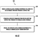
- FIG. 6 depicts a process 500 that can be performed by the service tool wireless access management system 10 of FIG. 1 as shown and described herein and/or by variations thereon.
- Various aspects of the process 500 can be carried out using one or more sensors, one or more processors, and/or one or more machines and/or controllers.
- sensors e.g., GPS, cameras, etc.
- the process 500 is described in reference to FIGS. 1-6 .
- At block 502 at least one processor 38, 40, 42 of the service tool wireless access management system 10 (e.g., at an equipment component 25) enables a wireless access interface 214 responsive to a wireless access request initiated through a service tool 22.
- the wireless access request can be relayed from the service tool 22 through a remote server 24 to the at least one processor via one or more communication pathways 28, 31.
- the service tool wireless access management system 10 can include a plurality of equipment components 25 and equipment controllers 26 having an associated instance of the wireless access interface 214 (e.g., wireless access interfaces 414A-414E) enabled responsive to the wireless access request.
- the wireless access interface 214 can be a first wireless access interface 214A of the equipment controller 26, and the wireless access request can be received on a second wireless access interface 214B of the equipment controller 26, where the second wireless access interface 214B has a reduced wireless communication range relative to the first wireless access interface 214A.
- the at least one processor can be further configured to enable the wireless access interface 214 responsive to an input received at a user interface 205 of the equipment controller 26.
- the at least one processor can be configured to confirm a location of the service tool 22 within a communication range threshold 304 of the wireless access interface 214 before enabling the wireless access interface 214.
- the wireless access request can include a request identifier, and enablement of the wireless access interface 214 may be further conditioned on determining that the request identifier matches an identifier 216 associated with the equipment controller 26.
- At block 504 at least one processor of the service tool wireless access management system 10 establishes a wireless communication session with the service tool 22 through the wireless access interface 214.
- the wireless communication session can provide the service tool 22 with access to one or more functions of an elevator controller 115. Functions can include monitoring of performance parameters, modifying performance parameters, change performance aspects, entering a test/diagnostic mode, and other such actions.
- At block 506 at least one processor of the service tool wireless access management system 10 disables the wireless access interface 214 responsive to a wireless communication termination event.
- the wireless communication termination event can be one or more of: a timeout period elapsing between enabling the wireless access interface 214 and establishing the wireless communication session, detecting that the service tool 22 is outside of a communication range threshold 304 of the wireless access interface 214, a timeout period elapsing since a last completed communication of the wireless communication session, a disable command received from the service tool, and an operating mode transition to a primary operating from an auxiliary operating mode.
- the wireless access interface 214 can be enabled responsive to a transition of the equipment controller 26 from the primary operating mode to the auxiliary operating mode.
- Process 500 can be repeated periodically to confirm whether a change in location of the service tool 22 necessitates a change in enablement of the wireless access interface 214.
- the process 500 can be repeated every N minutes, hourly, or at any other suitable period.
- the process 500 repeats at a faster rate when the service tool 22 transitions from an offsite location 142 to an onsite location 134.
- Computer readable program codes may include source codes, object codes, executable codes, and others.
- Computer readable mediums may be any type of media capable of being accessed by a computer, and may include Read Only Memory (ROM), Random Access Memory (RAM), a hard disk drive, a compact disc (CD), a digital video disc (DVD), or other forms.
- ROM Read Only Memory
- RAM Random Access Memory
- CD compact disc
- DVD digital video disc
- a component may be, but is not limited to, a process running on a processor, a processor, an object, an executable, a thread of execution, a program, and/or a computer. It is understood that an application running on a server and the server may be a component.
- One or more components may reside within a process and/or thread of execution and a component may be localized on one computer and/or distributed between two or more computers.
Landscapes
- Engineering & Computer Science (AREA)
- Computer Networks & Wireless Communication (AREA)
- Automation & Control Theory (AREA)
- Signal Processing (AREA)
- Theoretical Computer Science (AREA)
- General Engineering & Computer Science (AREA)
- Physics & Mathematics (AREA)
- General Physics & Mathematics (AREA)
- Computer Security & Cryptography (AREA)
- Computing Systems (AREA)
- Computer Hardware Design (AREA)
- Indicating And Signalling Devices For Elevators (AREA)
- Mobile Radio Communication Systems (AREA)
- Selective Calling Equipment (AREA)
Abstract
Description
- The present disclosure relates to equipment service systems, and more particularly, to service tool wireless access management.
- Current service tools used for accessing equipment controllers (e.g., elevator controllers) typically rely on using a separate hardware tool that physically plugs into an equipment control system. The physical connection ensures that the service tool is used by an individual who is physically present at a specific location when using the service tool. Being physically present helps to ensure that a user of the service tool can observe environmental conditions, such as the presence of other people. As networked/wireless service tools are used in place of physically connected service tools, a wireless network interface is desirable. Keeping a wireless network interface active to communicate with a wireless-enabled service tool at the location of the equipment consumes power even if the wireless network interface is only used occasionally for servicing events.
- According to some embodiments, a service tool wireless access management system is provided. The service tool wireless access management system includes a wireless access interface and an equipment controller of an equipment service system. The equipment controller includes at least one processor configured to enable the wireless access interface responsive to a wireless access request initiated through a service tool, establish a wireless communication session with the service tool through the wireless access interface, and disable the wireless access interface responsive to a wireless communication termination event.
- In addition to one or more of the features described above or below, or as an alternative, further embodiments may include where the wireless access request is relayed from the service tool through a remote server to the at least one processor via one or more communication pathways.
- In addition to one or more of the features described above or below, or as an alternative, further embodiments may include a plurality of equipment components of the equipment service system having an associated instance of the wireless access interface enabled responsive to the wireless access request.
- In addition to one or more of the features described above or below, or as an alternative, further embodiments may include where the equipment controller is an elevator controller, and the wireless communication session provides the service tool with access to one or more functions of the elevator controller.
- In addition to one or more of the features described above or below, or as an alternative, further embodiments may include where the wireless access interface includes a first wireless access interface of the equipment controller, and the wireless access request is received on a second wireless access interface of the equipment controller, the second wireless access interface having a reduced wireless communication range relative to the first wireless access interface.
- In addition to one or more of the features described above or below, or as an alternative, further embodiments may include where the at least one processor is further configured to enable the wireless access interface responsive to an input received at a user interface of the equipment controller.
- In addition to one or more of the features described above or below, or as an alternative, further embodiments may include where a location of the service tool within a communication range threshold of the wireless access interface is confirmed before enabling the wireless access interface.
- In addition to one or more of the features described above or below, or as an alternative, further embodiments may include where the wireless communication termination event comprises one or more of: a timeout period elapsing between enabling the wireless access interface and establishing the wireless communication session, detecting that the service tool is outside of a communication range threshold of the wireless access interface, a timeout period elapsing since a last completed communication of the wireless communication session, a disable command received from the service tool, and an operating mode transition to a primary operating from an auxiliary operating mode of the equipment controller.
- In addition to one or more of the features described above or below, or as an alternative, further embodiments may include where the wireless access interface is enabled responsive to a transition of the equipment controller from the primary operating mode to the auxiliary operating mode, wherein the transition is based on a condition detected at one or more of: an input interface, a restricted-access interface, a scanner interface, and at least one sensor.
- In addition to one or more of the features described above or below, or as an alternative, further embodiments may include where the wireless access request includes a request identifier, and enablement of the wireless access interface is further conditioned on determining that the request identifier matches an identifier associated with the equipment controller.
- According to some embodiments, a method of service tool wireless access management is provided. The method includes enabling a wireless access interface of an equipment service system responsive to a wireless access request initiated through a service tool. A wireless communication session with the service tool is enabled through the wireless access interface, and the wireless access interface is disabled responsive to a wireless communication termination event.
- The wireless access request may be relayed from the service tool through a remote server to at least one processor of an equipment controller via one or more communication pathways.
- The method may further comprise enabling an associated instance of the wireless access interface of a plurality of equipment components of the equipment service system responsive to the wireless access request.
- The method may further comprise: providing the service tool with access to one or more functions of an elevator controller of the equipment service system through the wireless communication session.
- The wireless access interface may comprise a first wireless access interface of an equipment controller, and the method may further comprise receiving the wireless access request on a second wireless access interface of the equipment controller, the second wireless access interface having a reduced wireless communication range relative to the first wireless access interface.
- The method may further comprise: enabling the wireless access interface responsive to an input received at a user interface of an equipment controller of the equipment service system.
- The method may further comprise: confirming a location of the service tool within a communication range threshold of the wireless access interface before enabling the wireless access interface.
- The wireless communication termination event may comprise one or more of: a timeout period elapsing between enabling the wireless access interface and establishing the wireless communication session, detecting that the service tool is outside of a communication range threshold of the wireless access interface, a timeout period elapsing since a last completed communication of the wireless communication session, a disable command received from the service tool, and an operating mode transition to a primary operating from an auxiliary operating mode of an equipment controller of the equipment service system.
- The method may further comprise: enabling the wireless access interface responsive to a transition of the equipment controller from the primary operating mode to the auxiliary operating mode, wherein the transition is based on a condition detected at one or more of: an input interface, a restricted-access interface, a scanner interface, and at least one sensor.
- The wireless access request may comprise a request identifier, and enablement of the wireless access interface may be further conditioned on determining that the request identifier matches an identifier associated with an equipment controller of the equipment service system.
- Technical effects of embodiments of the present disclosure include selectively enabling and disabling a wireless access interface proximate to a service location for establishing a wireless communication session with a service tool as needed.
- The foregoing features and elements may be combined in various combinations without exclusivity, unless expressly indicated otherwise. These features and elements as well as the operation thereof will become more apparent in light of the following description and the accompanying drawings. However, it should be understood that the following description and drawings are intended to be exemplary in nature and non-limiting.
- Various features will become apparent to those skilled in the art from the following detailed description of the disclosed non-limiting embodiments. The drawings that accompany the detailed description can be briefly described as follows:
-
FIG. 1 is a schematic illustration of an equipment service system as one, non-limiting, exemplary embodiment of the present disclosure; -
FIG. 2 is a schematic illustration of an elevator system that may employ various embodiments of the present disclosure; -
FIG. 3 is a schematic illustration of user and communication interfaces of an equipment controller in accordance with an embodiment of the present disclosure; -
FIG. 4 is a schematic illustration of communication range thresholds in accordance with an embodiment of the present disclosure; -
FIG. 5 is a schematic illustration of wireless access interfaces at various positions in accordance with an embodiment of the present disclosure; and -
FIG. 6 is a flowchart illustrating a method of service tool wireless access management in accordance with an embodiment of the present disclosure. - A detailed description of one or more embodiments of the disclosed apparatus and method are presented herein by way of exemplification and not limitation with reference to the Figures.
- Referring to
FIG. 1 , an exemplary embodiment of anequipment service system 20, which may include, or may use portions of, aservice tool 22, aremote server 24, and at least oneequipment component 25 with at least oneequipment controller 26. Theservice tool 22 may communicate with theremote server 24 and/or theequipment controller 26 overrespective communication pathways communication pathways remote server 24 can facilitate communication between theequipment controller 26 and theservice tool 22. One ormore communication pathways 31 between theremote server 24 andequipment controller 26 can enable remote access, for instance, for theservice tool 22 to request enablement ofcommunication pathway 30. Thus, information can flow overcommunication pathways equipment controller 26 and theservice tool 22 usingcommunication pathway 30 upon enablement of a wireless access interface of theequipment controller 26.Communication pathway 31 can use a different protocol for longer distance secure communication than protocols used bycommunication pathways - The
service tool 22 may include auser interface 32 that facilitates system interaction with a user (e.g., an equipment repairperson/service technician). Non-limiting examples of theservice tool 22 may include a smartphone, a tablet computer, laptop computer, and other electronic devices. Theremote server 24 may be cloud-based (i.e., in a cloud network environment). Theequipment service system 20 generally controls the flow of information between theservice tool 22, theremote server 24 and/or theequipment controller 26. In some embodiments, theservice tool 22 may provide an interface to one or more remotely executed applications with reduced local code execution. In one embodiment, theremote server 24 and theequipment controller 26 may be owned and/or controlled by a common company. - The
equipment service system 20 may further include at least one site (i.e., two illustrated as 34, 36 inFIG. 1 ). Eachsite 34, 36 may include at least one equipment controller 26 (i.e., three illustrated for eachsite 34, 36) operable to control one ormore equipment components 25. Non-limiting examples ofsites 34, 36 may be a building, a set of floors within a building, a portion of a floor within a building, a collection of buildings, and others. A non-limiting example of anequipment controller 26 may be an elevator controller that can be serviced by the manufacturer of the elevator, and the one ormore equipment components 25 can be one or more elevator components such as elevator cars. Theservice tool 22, theremote server 24, and theequipment controller 26 may each includerespective processors 38, 40, 42 (e.g., microprocessors), andstorage mediums - In the example of
FIG. 1 , a service tool wirelessaccess management system 10 can include theservice tool 22 and theequipment controller 26, where various location-based operations can be distributed between either or both of theservice tool 22 and theequipment controller 26. For example, at least oneprocessor 38 of theservice tool 22 can determine whether theservice tool 22 is located at a predetermined service location of anequipment service system 20 and/or at least oneprocessor 42 of theequipment controller 26 can determine/confirm the location of theservice tool 22. Further, theremote server 24 may/may also determine or verify the location of theservice tool 22. One or more location determination techniques can be employed, such as use of global positioning system (GPS) data, network address information, and proximity detection, etc. The predetermined service location can be defined in terms of being "local" or "remote", e.g., at one of thesites 34, 36 or not at one of thesites 34, 36. For instance, if theservice tool 22 is locally atsite 34, then theservice tool 22 may be considered remote from site 36. "Local" can be defined being on-site (e.g., within a building) or proximate to a specific predetermined location within and/or near the site, depending upon the technology used. For instance, "local" can be defined as being within signal communication range for direct wireless communication of the wireless communication protocol used, such as Wi-Fi. In one embodiment, "local" can be defined as being within a specific geospatial area (e.g., certain GPS coordinates, certain cellular triangulation area, etc.). "Remote" can be defined as an off-site location or out of wireless transmission range. Theremote server 24 can be used to enable wireless access atsites 34, 36 for theservice tool 22 and may provide authentication services. -
FIG. 2 is a perspective view of anelevator system 101 including anelevator car 103, acounterweight 105, one or moreload bearing members 107, aguide rail 109, amachine 111, aposition encoder 113, and anelevator controller 115. Theelevator system 101 includes examples ofvarious equipment components 25 ofFIG. 1 and predetermined service locations (e.g., a generalonsite location 134, atvarious landings 125, at alocation 136 withinelevator car 103, at alocation 140 proximate tomachine 111, at apit location 138, incontroller room 121, or any other desired location), where theelevator controller 115 is an example of theequipment controller 26 ofFIG. 1 . For instance, theonsite location 134 can be within a building/structure that includes theelevator system 101, while anoffsite location 142 can be external to the building/structure that includes theelevator system 101. - In the example of
FIG. 2 , theelevator car 103 andcounterweight 105 are connected to each other by theload bearing members 107. Theload bearing members 107 may be, for example, ropes, steel cables, and/or coated-steel belts. Thecounterweight 105 is configured to balance a load of theelevator car 103 and is configured to facilitate movement of theelevator car 103 concurrently and in an opposite direction with respect to thecounterweight 105 within anelevator shaft 117 and along theguide rail 109. Theload bearing members 107 engage themachine 111, which is part of an overhead structure of theelevator system 101. Themachine 111 is configured to control movement between theelevator car 103 and thecounterweight 105. The position encoder 113 may be mounted on an upper sheave of a speed-governor system 119 and may be configured to provide position signals related to a position of theelevator car 103 within theelevator shaft 117. In other embodiments, theposition encoder 113 may be directly mounted to a moving component of themachine 111, or may be located in other positions and/or configurations as known in the art. - The
elevator controller 115 can be located, as shown, in acontroller room 121 of theelevator shaft 117 and is configured to control the operation of theelevator system 101, and particularly theelevator car 103. For example, theelevator controller 115 may provide drive signals to themachine 111 to control the acceleration, deceleration, leveling, stopping, etc. of theelevator car 103. Theelevator controller 115 may also be configured to receive position signals from theposition encoder 113. When moving up or down within theelevator shaft 117 alongguide rail 109, theelevator car 103 may stop at one ormore landings 125 as controlled by theelevator controller 115. Although shown in acontroller room 121, those of skill in the art will appreciate that theelevator controller 115 can be located, distributed between, and/or configured in other locations or positions within theelevator system 101. In some embodiments, theelevator controller 115 can be configured to control features within theelevator car 103, including, but not limited to, lighting, display screens, music, spoken audio words, etc. - The
machine 111 may include a motor or similar driving mechanism and an optional braking system. In accordance with embodiments of the disclosure, themachine 111 is configured to include an electrically driven motor. The power supply for the motor may be any power source, including a power grid, which, in combination with other components, is supplied to the motor. Although shown and described with a rope-based load bearing system, elevator systems that employ other methods and mechanisms of moving an elevator car within an elevator shaft, such as hydraulics, ropeless, or any other methods, may employ embodiments of the present disclosure.FIG. 2 is merely a non-limiting example presented for illustrative and explanatory purposes. -
FIG. 3 depicts an example ofinterfaces 200 of theequipment controller 26 ofFIG. 1 that can be used to establish a wireless communication session with theservice tool 22 ofFIG. 1 . One or more instances of theinterfaces 200 can be installed at eachsite 34, 36 to serve various purposes during a primary operating mode (e.g., normal operation) and one or more auxiliary operating modes (e.g., service mode, inspection mode, error state modes, etc.), including enabling and disabling wireless communication upon transitions between modes or within modes. For instance, theinterfaces 200 can be located in whole or in part within theelevator car 103 ofFIG. 2 as part of an elevator control interface. Further, theinterfaces 200 can be located at one or more of thelandings 125 ofFIG. 2 , incontroller room 121 ofFIG. 2 , and/or at other locations. Theinterfaces 200 can provide various inputs and/or outputs toequipment controller 26 ofFIG. 1 . For example, theinterfaces 200 can include adisplay 202, aninput interface 204 including a plurality ofbuttons 206, a restricted-access input interface 208, ascanner interface 209, and at least onewireless access interface 214. In some embodiments, thedisplay 202 is touch-sensitive and operable to receive user inputs. Thedisplay 202,input interface 204, restricted-access input interface 208, and/orscanner interface 209 are collectively referred to asuser interfaces 205. The restricted-access input interface 208 can include anaccess control 210, such as a lock, operable to restrict input unless an associatedkey 212 is used (e.g., a fire key switch). The restricted-access input interface 208 may be used to transition between a primary operating mode and an auxiliary operating mode. Thescanner interface 209 can include a camera, a radio-frequency identification (RFID) transceiver, a barcode reader, a fingerprint reader, and/or similar interface operable to detect information about a user. For instance, thescanner interface 209 can identify an authorized user/user type based on an identification card/device, biometric data, and/or other observable information. Aninterface controller 201 can process inputs and outputs of theinterfaces 200 as a data concentrator of theequipment controller 26. For example, theinterfaces 200 can be integrated into theelevator car 103 ofFIG. 2 , while all or a portion of theequipment controller 26 ofFIG. 1 may be located in theelevator controller 115 atcontroller room 121. Theinterface controller 201 can also detect the presence of a user through one ormore sensors 218, such as door/gate sensors, load sensors, thermal sensors, audio sensors, and/or other types of sensors known in the art. Input from theinput interface 204,scanner interface 209, and/orsensors 218 may also or alternatively be used to transition between the primary operating mode and the auxiliary operating mode based on a condition detected. - The
wireless access interface 214 can be used to establish various types of wireless communication, such as thecommunication pathway 30 ofFIG. 1 . In some embodiments, there are multiple instances of thewireless access interface 214 that may have different communication ranges, as further illustrated in conjunction withFIG. 4 . For instance, embodiments may have a singlecommunication range threshold 304 defined relative to alocation 302 of thewireless access interface 214. Other embodiments can include a firstcommunication range threshold 308 for a firstwireless access interface 214A and a secondcommunication range threshold 310 for a secondwireless access interface 214B at alocation 306, where the secondwireless access interface 214B has a reduced wireless communication range relative to the firstwireless access interface 214A (as indicated by a smaller diameter of the secondcommunication range threshold 310 relative to the first communication range threshold 308). For instance, the firstwireless access interface 214A may be a Wi-Fi interface, while the secondwireless access interface 214B may be a Bluetooth® or NFC communication interface. Thecommunication range thresholds service tool 22. For example, in some embodiments, thewireless access interface 214 is not enabled until theservice tool 22 is within thecommunication range threshold 304 atlocation 302, which may be confirmed by GPS coordinates provided from theservice tool 22 to theremote server 24. In some embodiments, the firstwireless access interface 214A is not enabled until theservice tool 22 is within the secondcommunication range threshold 310. The secondwireless access interface 214B may use less power than the firstwireless access interface 214A, and selectively enabling/disabling the firstwireless access interface 214A reduces overall power consumption and can reduce exposure to potential cybersecurity threats. Thecommunication range thresholds service tool 22 was last within thecommunication range thresholds - With further reference to
FIG. 3 , anidentifier 216 can be associated with theinterfaces 200 and acorresponding equipment controller 26 ofFIG. 1 . Theidentifier 216 can be an alpha-numeric code or symbol (e.g., a bar code or quick response code) that identifies a location of thewireless access interface 214 to be accessed. In some embodiments, a user of theservice tool 22 can photograph, scan, or manually input information associated with theidentifier 216 to target communication with a specific instance of thewireless access interface 214, for instance, where multiple otherwireless access interfaces 214 are also in close physical proximity to theservice tool 22. Where theidentifier 216 is used, a wireless access request from theservice tool 22 can include a request identifier, and enablement of thewireless access interface 214 can be conditioned on determining that the request identifier matches theidentifier 216 associated with theequipment controller 26. As depicted in the example ofFIG. 5 , a location may include anelevator bank 400 includeelevator shafts corresponding elevator cars control room 406, and correspondingwireless access interfaces wireless access interface 214. The use of identifiers, such asidentifier 216 ofFIG. 3 , can ensure that a user of theservice tool 22 is interfacing with the desired target, where wireless access interfaces 414A-414E may have an overlapping communication range, particularly when theelevator cars 404A-404D are at or near a same height withinelevator shafts 402A-402D. - Entering inputs directly through the
user interfaces 205 ofFIG. 3 can also be used to selectively enable or confirm enablement of a wireless access interface. For example, each of theelevator cars 404A-404D andcontrol room 406 may have instances of theuser interfaces 205. A sequence or combination of pressingbuttons 206, using key 212 on restricted-access input interface 208, and/or making touch-based inputs throughdisplay 202 at a particular location can enable or confirm enablement of one or more of the wireless access interfaces 414A-414E ofFIG. 5 . As an example, theservice tool 22 may request enablement of the wireless access interfaces 414A-414E, and entry of a code or sequence throughuser interfaces 205 atelevator car 404B may result in keepingwireless access interface 414B enabled while disablingwireless access interfaces - In the example of
FIG. 5 , the wireless access interfaces 414A-414E are normally disabled to conserve power and/or reduce exposure to cyberattacks. Alternatively or in addition to requesting enablement of one or more of the wireless access interfaces 414A-414E through theservice tool 22, the user can push one or more of thebuttons 206 ofFIG. 3 or a press/toggle a switch to enable or confirm enablement of one or more of the wireless access interfaces 414A-414E. For instance, a combination ofbutton 206 pushes could include simultaneously pushing a combination ofbuttons 206 for at least a minimum time period and/or entering a predetermined sequence. In some embodiments, theservice tool 22 receives a code from theremote server 24 indicating the needed combination or sequence. Similarly, in addition to requesting enablement of one or more of the wireless access interfaces 414A-414E through theservice tool 22 or to confirm user presence, thescanner interface 209 can be used to capture scanned user data, such as an RFID-enabled card, a barcode on an identification card or work order, and/or biometric data of an authorized user. In some embodiments, upon enablement of one of the wireless access interfaces 414A-414E, other instances of the wireless access interfaces 414A-414E are enabled. For instance, if a user of theservice tool 22 enables thewireless access interface 414E, theremote server 24 or other system may also enable wireless access interfaces 414A-414D. Various wireless communication termination events can result in disabling one or more of the wireless access interfaces 414A-414E as further described in reference toFIG. 6 . -
FIG. 6 depicts aprocess 500 that can be performed by the service tool wirelessaccess management system 10 ofFIG. 1 as shown and described herein and/or by variations thereon. Various aspects of theprocess 500 can be carried out using one or more sensors, one or more processors, and/or one or more machines and/or controllers. For example, some aspects of the flow process involve sensors (e.g., GPS, cameras, etc.), as described above, in communication with a processor or other control device and transmit detection information thereto. Theprocess 500 is described in reference toFIGS. 1-6 . - At
block 502, at least oneprocessor wireless access interface 214 responsive to a wireless access request initiated through aservice tool 22. The wireless access request can be relayed from theservice tool 22 through aremote server 24 to the at least one processor via one ormore communication pathways access management system 10 can include a plurality ofequipment components 25 andequipment controllers 26 having an associated instance of the wireless access interface 214 (e.g., wireless access interfaces 414A-414E) enabled responsive to the wireless access request. Thewireless access interface 214 can be a firstwireless access interface 214A of theequipment controller 26, and the wireless access request can be received on a secondwireless access interface 214B of theequipment controller 26, where the secondwireless access interface 214B has a reduced wireless communication range relative to the firstwireless access interface 214A. The at least one processor can be further configured to enable thewireless access interface 214 responsive to an input received at auser interface 205 of theequipment controller 26. The at least one processor can be configured to confirm a location of theservice tool 22 within acommunication range threshold 304 of thewireless access interface 214 before enabling thewireless access interface 214. The wireless access request can include a request identifier, and enablement of thewireless access interface 214 may be further conditioned on determining that the request identifier matches anidentifier 216 associated with theequipment controller 26. - At
block 504, at least one processor of the service tool wirelessaccess management system 10 establishes a wireless communication session with theservice tool 22 through thewireless access interface 214. The wireless communication session can provide theservice tool 22 with access to one or more functions of anelevator controller 115. Functions can include monitoring of performance parameters, modifying performance parameters, change performance aspects, entering a test/diagnostic mode, and other such actions. - At
block 506, at least one processor of the service tool wirelessaccess management system 10 disables thewireless access interface 214 responsive to a wireless communication termination event. The wireless communication termination event can be one or more of: a timeout period elapsing between enabling thewireless access interface 214 and establishing the wireless communication session, detecting that theservice tool 22 is outside of acommunication range threshold 304 of thewireless access interface 214, a timeout period elapsing since a last completed communication of the wireless communication session, a disable command received from the service tool, and an operating mode transition to a primary operating from an auxiliary operating mode. Thewireless access interface 214 can be enabled responsive to a transition of theequipment controller 26 from the primary operating mode to the auxiliary operating mode. -
Process 500 can be repeated periodically to confirm whether a change in location of theservice tool 22 necessitates a change in enablement of thewireless access interface 214. For example, theprocess 500 can be repeated every N minutes, hourly, or at any other suitable period. In some embodiments, theprocess 500 repeats at a faster rate when theservice tool 22 transitions from anoffsite location 142 to anonsite location 134. - The various functions described above may be implemented or supported by a computer program that is formed from computer readable program codes and that is embodied in a computer readable medium. Computer readable program codes may include source codes, object codes, executable codes, and others. Computer readable mediums may be any type of media capable of being accessed by a computer, and may include Read Only Memory (ROM), Random Access Memory (RAM), a hard disk drive, a compact disc (CD), a digital video disc (DVD), or other forms.
- Terms used herein such as component, module, system, and the like are intended to refer to a computer-related entity, either hardware, a combination of hardware and software, or software execution. By way of example, a component may be, but is not limited to, a process running on a processor, a processor, an object, an executable, a thread of execution, a program, and/or a computer. It is understood that an application running on a server and the server may be a component. One or more components may reside within a process and/or thread of execution and a component may be localized on one computer and/or distributed between two or more computers.
- While the present disclosure is described with reference to exemplary embodiments, it will be understood by those skilled in the art that various changes may be made and equivalents may be substituted without departing from the spirit and scope of the present disclosure. In addition, various modifications may be applied to adapt the teachings of the present disclosure to particular situations, applications, and/or materials, without departing from the essential scope thereof. The present disclosure is thus not limited to the particular examples disclosed herein, but includes all embodiments falling within the scope of the appended claims.
Claims (15)
- A service tool wireless access management system comprising:a wireless access interface; andan equipment controller of an equipment service system comprising at least one processor configured to:enable the wireless access interface responsive to a wireless access request initiated through a service tool;establish a wireless communication session with the service tool through the wireless access interface; anddisable the wireless access interface responsive to a wireless communication termination event.
- The service tool wireless access management system set forth in claim 1, wherein the wireless access request is relayed from the service tool through a remote server to the at least one processor via one or more communication pathways.
- The service tool wireless access management system set forth in claim 1 or 2, further comprising a plurality of equipment components of the equipment service system having an associated instance of the wireless access interface enabled responsive to the wireless access request.
- The service tool wireless access management system set forth in claim 1, 2 or 3, wherein the equipment controller comprises an elevator controller, and the wireless communication session provides the service tool with access to one or more functions of the elevator controller.
- The service tool wireless access management system set forth in any preceding claim, wherein the wireless access interface comprises a first wireless access interface of the equipment controller, and the wireless access request is received on a second wireless access interface of the equipment controller, the second wireless access interface having a reduced wireless communication range relative to the first wireless access interface.
- The service tool wireless access management system set forth in any preceding claim, wherein the at least one processor is further configured to enable the wireless access interface responsive to an input received at a user interface of the equipment controller.
- The service tool wireless access management system set forth in any preceding claim, wherein a location of the service tool within a communication range threshold of the wireless access interface is confirmed before enabling the wireless access interface.
- The service tool wireless access management system set forth in any preceding claim, wherein the wireless communication termination event comprises one or more of: a timeout period elapsing between enabling the wireless access interface and establishing the wireless communication session, detecting that the service tool is outside of a communication range threshold of the wireless access interface, a timeout period elapsing since a last completed communication of the wireless communication session, a disable command received from the service tool, and an operating mode transition to a primary operating from an auxiliary operating mode of the equipment controller.
- The service tool wireless access management system set forth in claim 8, wherein the wireless access interface is enabled responsive to a transition of the equipment controller from the primary operating mode to the auxiliary operating mode, wherein the transition is based on a condition detected at one or more of: an input interface, a restricted-access interface, a scanner interface, and at least one sensor.
- The service tool wireless access management system set forth in any preceding claim, wherein the wireless access request comprises a request identifier, and enablement of the wireless access interface is further conditioned on determining that the request identifier matches an identifier associated with the equipment controller.
- A method of service tool wireless access management comprising:enabling a wireless access interface of an equipment service system responsive to a wireless access request initiated through a service tool;establishing a wireless communication session with the service tool through the wireless access interface; anddisabling the wireless access interface responsive to a wireless communication termination event.
- The method set forth in claim 11, wherein the wireless access request is relayed from the service tool through a remote server to at least one processor of an equipment controller via one or more communication pathways.
- The method set forth in claim 11 or 12, further comprising enabling an associated instance of the wireless access interface of a plurality of equipment components of the equipment service system responsive to the wireless access request.
- The method set forth in claim 11, 12 or 13, further comprising:
providing the service tool with access to one or more functions of an elevator controller of the equipment service system through the wireless communication session. - The method set forth in any of claims 11 to 14, wherein the wireless access interface comprises a first wireless access interface of an equipment controller, and the method further comprises receiving the wireless access request on a second wireless access interface of the equipment controller, the second wireless access interface having a reduced wireless communication range relative to the first wireless access interface.
Applications Claiming Priority (1)
| Application Number | Priority Date | Filing Date | Title |
|---|---|---|---|
| US15/882,225 US10939477B2 (en) | 2018-01-29 | 2018-01-29 | Service tool wireless access management |
Publications (2)
| Publication Number | Publication Date |
|---|---|
| EP3518610A1 true EP3518610A1 (en) | 2019-07-31 |
| EP3518610B1 EP3518610B1 (en) | 2023-11-29 |
Family
ID=65516409
Family Applications (1)
| Application Number | Title | Priority Date | Filing Date |
|---|---|---|---|
| EP19154240.6A Active EP3518610B1 (en) | 2018-01-29 | 2019-01-29 | Service tool wireless access management system |
Country Status (4)
| Country | Link |
|---|---|
| US (1) | US10939477B2 (en) |
| EP (1) | EP3518610B1 (en) |
| CN (2) | CN110099431A (en) |
| ES (1) | ES2965903T3 (en) |
Cited By (3)
| Publication number | Priority date | Publication date | Assignee | Title |
|---|---|---|---|---|
| WO2021099411A1 (en) * | 2019-11-19 | 2021-05-27 | Siemens Schweiz Ag | Remote activation of the wireless service interface of a control device via a radio interface |
| WO2021099410A1 (en) * | 2019-11-19 | 2021-05-27 | Siemens Schweiz Ag | Remote activation of the wireless service interface of a control device using a peripheral device |
| WO2021099412A1 (en) * | 2019-11-19 | 2021-05-27 | Siemens Schweiz Ag | Remote activation of the wireless service interface of a control device via a bus system |
Families Citing this family (6)
| Publication number | Priority date | Publication date | Assignee | Title |
|---|---|---|---|---|
| EP3613693B1 (en) * | 2018-08-17 | 2022-10-05 | Otis Elevator Company | Elevator system with sensors |
| CN111836340B (en) * | 2020-07-08 | 2023-06-09 | 上海金智晟东电力科技有限公司 | Interactive operation and maintenance method and system for column feeder terminal |
| CN116710385A (en) * | 2021-01-08 | 2023-09-05 | 通力股份公司 | Control of the operation of the conveyor system |
| CN117062767A (en) * | 2021-03-22 | 2023-11-14 | 通力股份公司 | Computer-implemented methods and apparatus associated with user applications related to personnel transportation systems |
| CN113769401B (en) * | 2021-09-13 | 2024-09-03 | 网易(杭州)网络有限公司 | Information processing method and device, storage medium and electronic equipment |
| WO2024002695A1 (en) * | 2022-06-29 | 2024-01-04 | Inventio Ag | Method for communicating with an elevator system by means of a mobile terminal |
Family Cites Families (32)
| Publication number | Priority date | Publication date | Assignee | Title |
|---|---|---|---|---|
| AU2002343514A1 (en) | 2002-10-15 | 2004-05-04 | Otis Elevator Company | Elevator wireless communication infrastructure using piconet modules |
| JP4423261B2 (en) | 2003-11-18 | 2010-03-03 | オーチス エレベータ カンパニー | Elevator governor device |
| ES2626406T3 (en) | 2009-09-16 | 2017-07-25 | Otis Elevator Company | Remote access of an elevator control system with multiple subsystems |
| CN103596865B (en) * | 2011-05-10 | 2015-11-25 | 奥的斯电梯公司 | Manage the remote control of the elevator system |
| CN102765643B (en) | 2012-05-31 | 2015-06-17 | 天津大学 | Elevator fault diagnosis and early-warning method based on data drive |
| JP5942684B2 (en) * | 2012-08-07 | 2016-06-29 | 富士通株式会社 | Communication control device and communication control method |
| US9585091B2 (en) * | 2012-08-17 | 2017-02-28 | Qualcomm Incorporated | Systems and methods for low power wake up signal and operations for WLAN |
| EP2755429A1 (en) * | 2013-01-10 | 2014-07-16 | Fujitsu Limited | Mobility and connection management of low power wireless communication apparatuses |
| KR102002407B1 (en) * | 2013-05-07 | 2019-07-23 | 삼성전자주식회사 | Method and apparatus for transmitting contents in a portable terminal |
| KR20140134562A (en) * | 2013-05-14 | 2014-11-24 | 삼성전자주식회사 | Method and divece for controlling a communication unit using a magnetic sensor |
| US9998326B2 (en) * | 2014-02-13 | 2018-06-12 | General Electric Company | Systems and methods for touch-less commissioning of intelligent electronic devices |
| US20150329316A1 (en) * | 2014-05-13 | 2015-11-19 | Wen-Sung Lee | Smart elevator control device |
| US9591565B2 (en) * | 2014-05-16 | 2017-03-07 | Intel Corporation | Method, system and apparatus for providing coexistence between low power stations and non-low power stations |
| US9690272B2 (en) * | 2015-02-16 | 2017-06-27 | Polaris Tech Global Limited | Indoor automation and control method and system thereof using RFID-to-Bluetooth selective adapter |
| EP3124418A1 (en) | 2015-07-28 | 2017-02-01 | Inventio AG | Elevator controller with wireless access point |
| US10273117B2 (en) * | 2015-09-30 | 2019-04-30 | Mastercard International Incorporated | Controlling an elevator car to take a user to a destination floor based on calendar information from a mobile device |
| ITUB20154627A1 (en) | 2015-10-13 | 2017-04-13 | Sematic S P A | PROCEDURE FOR MAINTENANCE OF AN ELECTROMECHANICAL DEVICE |
| US20190028886A1 (en) | 2016-01-21 | 2019-01-24 | Philips Lighting Holding B.V. | Configuration system for a set of wireless network devices |
| KR102015743B1 (en) * | 2016-03-14 | 2019-08-28 | 미쓰비시덴키 가부시키가이샤 | Elevator system |
| US10343874B2 (en) | 2016-04-06 | 2019-07-09 | Otis Elevator Company | Wireless device installation interface |
| JP6656084B2 (en) * | 2016-05-23 | 2020-03-04 | キヤノン株式会社 | Communication device, communication method, and program |
| CN105923484A (en) | 2016-06-29 | 2016-09-07 | 北京利亚德视频技术有限公司 | Visual rescue elevator and visual rescue method for elevator |
| CN106125621B (en) * | 2016-08-10 | 2018-10-30 | 深圳奥尼电子股份有限公司 | security monitoring system and security monitoring method |
| CN110023223B (en) * | 2016-11-30 | 2021-09-28 | 因温特奥股份公司 | Configuring access rights to an elevator control system |
| CN206336872U (en) | 2016-11-30 | 2017-07-18 | 浙江捷轩智能科技有限公司 | A kind of elevator Internet of Things monitoring management device |
| CN106744111B (en) | 2016-12-05 | 2023-04-07 | 深圳市图焌科技有限公司 | Elevator maintenance management system and method based on Bluetooth and mobile data communication technology |
| CN106946108B (en) | 2017-03-29 | 2019-04-16 | 深圳市旺龙智能科技有限公司 | An elevator control system and method |
| CN206872187U (en) * | 2017-04-12 | 2018-01-12 | 联盟电梯(苏州)有限公司 | A kind of Intelligent control apparatus for elevator based on mobile communication technology |
| EP3393149B1 (en) * | 2017-04-18 | 2023-03-22 | Valmet Automation Oy | Method and arrangement for activating wireless connection |
| US11447366B2 (en) * | 2017-06-23 | 2022-09-20 | Otis Elevator Company | Determination for motion of passenger over elevator car |
| US10244374B2 (en) * | 2017-07-17 | 2019-03-26 | Otis Elevator Company | Service tool proximity detection |
| EP3432276A1 (en) * | 2017-07-19 | 2019-01-23 | KONE Corporation | Wake-up procedure for a bluetooth smart lock |
-
2018
- 2018-01-29 US US15/882,225 patent/US10939477B2/en active Active
-
2019
- 2019-01-28 CN CN201910083114.XA patent/CN110099431A/en active Pending
- 2019-01-28 CN CN202311008138.1A patent/CN117202323A/en active Pending
- 2019-01-29 EP EP19154240.6A patent/EP3518610B1/en active Active
- 2019-01-29 ES ES19154240T patent/ES2965903T3/en active Active
Non-Patent Citations (2)
| Title |
|---|
| AVM: "Fritz!Box 3272 Service", 15 September 2017 (2017-09-15), pages 1 - 2, XP055595598, Retrieved from the Internet <URL:https://web.archive.org/web/20160915034026/https://en.avm.de/service/fritzbox/fritzbox-4020/knowledge-base/publication/show/106_Setting-up-the-FRITZ-Box-for-use-with-another-router/> [retrieved on 20190611] * |
| VIA: "VIA Alegro 100", 24 February 2017 (2017-02-24), XP055595606, Retrieved from the Internet <URL:https://web.archive.org/web/20170224074748/https://www.viatech.com/en/solutions/via-iot-studio/via-alegro-100/> [retrieved on 20190611] * |
Cited By (6)
| Publication number | Priority date | Publication date | Assignee | Title |
|---|---|---|---|---|
| WO2021099411A1 (en) * | 2019-11-19 | 2021-05-27 | Siemens Schweiz Ag | Remote activation of the wireless service interface of a control device via a radio interface |
| WO2021099410A1 (en) * | 2019-11-19 | 2021-05-27 | Siemens Schweiz Ag | Remote activation of the wireless service interface of a control device using a peripheral device |
| WO2021099412A1 (en) * | 2019-11-19 | 2021-05-27 | Siemens Schweiz Ag | Remote activation of the wireless service interface of a control device via a bus system |
| CN114731305A (en) * | 2019-11-19 | 2022-07-08 | 西门子瑞士有限公司 | Remote activation of the wireless service interface of the control device via the peripheral device |
| US11880191B2 (en) | 2019-11-19 | 2024-01-23 | Siemens Schweiz Ag | Remote activation of the wireless service interface of a control device via a bus system |
| US12047195B2 (en) | 2019-11-19 | 2024-07-23 | Siemens Schweiz Ag | Remote activation of the wireless service interface of a control device using a peripheral device |
Also Published As
| Publication number | Publication date |
|---|---|
| ES2965903T3 (en) | 2024-04-17 |
| EP3518610B1 (en) | 2023-11-29 |
| US10939477B2 (en) | 2021-03-02 |
| CN110099431A (en) | 2019-08-06 |
| CN117202323A (en) | 2023-12-08 |
| US20190239258A1 (en) | 2019-08-01 |
Similar Documents
| Publication | Publication Date | Title |
|---|---|---|
| EP3518610B1 (en) | Service tool wireless access management system | |
| US10669122B2 (en) | Service tool location-based function availability | |
| EP3536647B2 (en) | Authorization management and authorization request of elevator service request | |
| US20190202657A1 (en) | Testing for wireless beacons of elevator system and field installation of the elevator system | |
| KR102558463B1 (en) | Service tool proximity detection | |
| US10691779B2 (en) | Service tool credential management | |
| JP6747626B1 (en) | Elevator automatic call registration system | |
| US20240076162A1 (en) | Maintenance of a conveyor system | |
| CN110002289A (en) | For confirming the elevator automatic positioning of maintenance | |
| US20250013975A1 (en) | Delivery of package in buildings provided with elevators | |
| EP4149871B1 (en) | Access solution for conveyor systems | |
| CN111540094B (en) | Function control method, access control machine and storage medium | |
| KR102212673B1 (en) | Method, system and computer program for parking management using digital key for vehicle | |
| US20240059525A1 (en) | Elevator control | |
| US20230365379A1 (en) | Solution for detecting a maintenance mode operation of an elevator system | |
| US20250189316A1 (en) | Hosting of an individual | |
| US20230331517A1 (en) | Elevator control | |
| WO2023187248A1 (en) | Cleaning of an elevator car | |
| HK40123885A (en) | Hosting of an individual | |
| HK40118448A (en) | Cleaning of an elevator car | |
| CN119365406A (en) | Communication method with elevator equipment by means of mobile terminal |
Legal Events
| Date | Code | Title | Description |
|---|---|---|---|
| PUAI | Public reference made under article 153(3) epc to a published international application that has entered the european phase |
Free format text: ORIGINAL CODE: 0009012 |
|
| STAA | Information on the status of an ep patent application or granted ep patent |
Free format text: STATUS: THE APPLICATION HAS BEEN PUBLISHED |
|
| AK | Designated contracting states |
Kind code of ref document: A1 Designated state(s): AL AT BE BG CH CY CZ DE DK EE ES FI FR GB GR HR HU IE IS IT LI LT LU LV MC MK MT NL NO PL PT RO RS SE SI SK SM TR |
|
| AX | Request for extension of the european patent |
Extension state: BA ME |
|
| STAA | Information on the status of an ep patent application or granted ep patent |
Free format text: STATUS: REQUEST FOR EXAMINATION WAS MADE |
|
| 17P | Request for examination filed |
Effective date: 20200131 |
|
| RBV | Designated contracting states (corrected) |
Designated state(s): AL AT BE BG CH CY CZ DE DK EE ES FI FR GB GR HR HU IE IS IT LI LT LU LV MC MK MT NL NO PL PT RO RS SE SI SK SM TR |
|
| STAA | Information on the status of an ep patent application or granted ep patent |
Free format text: STATUS: EXAMINATION IS IN PROGRESS |
|
| 17Q | First examination report despatched |
Effective date: 20200715 |
|
| REG | Reference to a national code |
Ref legal event code: R079 Free format text: PREVIOUS MAIN CLASS: H04W0076100000 Ipc: H04W0004500000 Ref country code: DE Ref legal event code: R079 Ref document number: 602019042178 Country of ref document: DE Free format text: PREVIOUS MAIN CLASS: H04W0076100000 Ipc: H04W0004500000 |
|
| GRAP | Despatch of communication of intention to grant a patent |
Free format text: ORIGINAL CODE: EPIDOSNIGR1 |
|
| STAA | Information on the status of an ep patent application or granted ep patent |
Free format text: STATUS: GRANT OF PATENT IS INTENDED |
|
| RIC1 | Information provided on ipc code assigned before grant |
Ipc: H04W 92/18 20090101ALN20230323BHEP Ipc: H04L 12/12 20060101ALI20230323BHEP Ipc: H04W 4/02 20180101ALI20230323BHEP Ipc: H04W 4/50 20180101AFI20230323BHEP |
|
| RIC1 | Information provided on ipc code assigned before grant |
Ipc: H04W 92/18 20090101ALN20230327BHEP Ipc: H04L 12/12 20060101ALI20230327BHEP Ipc: H04W 4/02 20180101ALI20230327BHEP Ipc: H04W 4/50 20180101AFI20230327BHEP |
|
| INTG | Intention to grant announced |
Effective date: 20230412 |
|
| GRAJ | Information related to disapproval of communication of intention to grant by the applicant or resumption of examination proceedings by the epo deleted |
Free format text: ORIGINAL CODE: EPIDOSDIGR1 |
|
| REG | Reference to a national code |
Ref country code: DE Ref legal event code: R079 Free format text: PREVIOUS MAIN CLASS: H04W0004500000 Ipc: H04L0012120000 Ref document number: 602019042178 Country of ref document: DE |
|
| STAA | Information on the status of an ep patent application or granted ep patent |
Free format text: STATUS: EXAMINATION IS IN PROGRESS |
|
| GRAP | Despatch of communication of intention to grant a patent |
Free format text: ORIGINAL CODE: EPIDOSNIGR1 |
|
| STAA | Information on the status of an ep patent application or granted ep patent |
Free format text: STATUS: GRANT OF PATENT IS INTENDED |
|
| INTC | Intention to grant announced (deleted) | ||
| RIC1 | Information provided on ipc code assigned before grant |
Ipc: H04W 88/06 20090101ALN20230822BHEP Ipc: H04W 88/04 20090101ALN20230822BHEP Ipc: H04W 84/18 20090101ALN20230822BHEP Ipc: H04W 48/18 20090101ALN20230822BHEP Ipc: H04W 92/18 20090101ALN20230822BHEP Ipc: G06F 1/3287 20190101ALI20230822BHEP Ipc: G06F 1/3234 20190101ALI20230822BHEP Ipc: H04W 52/02 20090101ALI20230822BHEP Ipc: G06F 1/3209 20190101ALI20230822BHEP Ipc: B66B 1/34 20060101ALI20230822BHEP Ipc: H04L 12/12 20060101AFI20230822BHEP |
|
| INTG | Intention to grant announced |
Effective date: 20230920 |
|
| GRAS | Grant fee paid |
Free format text: ORIGINAL CODE: EPIDOSNIGR3 |
|
| GRAA | (expected) grant |
Free format text: ORIGINAL CODE: 0009210 |
|
| STAA | Information on the status of an ep patent application or granted ep patent |
Free format text: STATUS: THE PATENT HAS BEEN GRANTED |
|
| AK | Designated contracting states |
Kind code of ref document: B1 Designated state(s): AL AT BE BG CH CY CZ DE DK EE ES FI FR GB GR HR HU IE IS IT LI LT LU LV MC MK MT NL NO PL PT RO RS SE SI SK SM TR |
|
| REG | Reference to a national code |
Ref country code: GB Ref legal event code: FG4D |
|
| REG | Reference to a national code |
Ref country code: CH Ref legal event code: EP |
|
| REG | Reference to a national code |
Ref country code: DE Ref legal event code: R096 Ref document number: 602019042178 Country of ref document: DE |
|
| REG | Reference to a national code |
Ref country code: IE Ref legal event code: FG4D |
|
| REG | Reference to a national code |
Ref country code: LT Ref legal event code: MG9D |
|
| REG | Reference to a national code |
Ref country code: NL Ref legal event code: MP Effective date: 20231129 |
|
| PG25 | Lapsed in a contracting state [announced via postgrant information from national office to epo] |
Ref country code: GR Free format text: LAPSE BECAUSE OF FAILURE TO SUBMIT A TRANSLATION OF THE DESCRIPTION OR TO PAY THE FEE WITHIN THE PRESCRIBED TIME-LIMIT Effective date: 20240301 |
|
| PG25 | Lapsed in a contracting state [announced via postgrant information from national office to epo] |
Ref country code: IS Free format text: LAPSE BECAUSE OF FAILURE TO SUBMIT A TRANSLATION OF THE DESCRIPTION OR TO PAY THE FEE WITHIN THE PRESCRIBED TIME-LIMIT Effective date: 20240329 |
|
| PG25 | Lapsed in a contracting state [announced via postgrant information from national office to epo] |
Ref country code: LT Free format text: LAPSE BECAUSE OF FAILURE TO SUBMIT A TRANSLATION OF THE DESCRIPTION OR TO PAY THE FEE WITHIN THE PRESCRIBED TIME-LIMIT Effective date: 20231129 |
|
| REG | Reference to a national code |
Ref country code: ES Ref legal event code: FG2A Ref document number: 2965903 Country of ref document: ES Kind code of ref document: T3 Effective date: 20240417 |
|
| PG25 | Lapsed in a contracting state [announced via postgrant information from national office to epo] |
Ref country code: LT Free format text: LAPSE BECAUSE OF FAILURE TO SUBMIT A TRANSLATION OF THE DESCRIPTION OR TO PAY THE FEE WITHIN THE PRESCRIBED TIME-LIMIT Effective date: 20231129 Ref country code: IS Free format text: LAPSE BECAUSE OF FAILURE TO SUBMIT A TRANSLATION OF THE DESCRIPTION OR TO PAY THE FEE WITHIN THE PRESCRIBED TIME-LIMIT Effective date: 20240329 Ref country code: GR Free format text: LAPSE BECAUSE OF FAILURE TO SUBMIT A TRANSLATION OF THE DESCRIPTION OR TO PAY THE FEE WITHIN THE PRESCRIBED TIME-LIMIT Effective date: 20240301 Ref country code: BG Free format text: LAPSE BECAUSE OF FAILURE TO SUBMIT A TRANSLATION OF THE DESCRIPTION OR TO PAY THE FEE WITHIN THE PRESCRIBED TIME-LIMIT Effective date: 20240229 |
|
| REG | Reference to a national code |
Ref country code: AT Ref legal event code: MK05 Ref document number: 1637247 Country of ref document: AT Kind code of ref document: T Effective date: 20231129 |
|
| PG25 | Lapsed in a contracting state [announced via postgrant information from national office to epo] |
Ref country code: NL Free format text: LAPSE BECAUSE OF FAILURE TO SUBMIT A TRANSLATION OF THE DESCRIPTION OR TO PAY THE FEE WITHIN THE PRESCRIBED TIME-LIMIT Effective date: 20231129 |
|
| PG25 | Lapsed in a contracting state [announced via postgrant information from national office to epo] |
Ref country code: SE Free format text: LAPSE BECAUSE OF FAILURE TO SUBMIT A TRANSLATION OF THE DESCRIPTION OR TO PAY THE FEE WITHIN THE PRESCRIBED TIME-LIMIT Effective date: 20231129 Ref country code: RS Free format text: LAPSE BECAUSE OF FAILURE TO SUBMIT A TRANSLATION OF THE DESCRIPTION OR TO PAY THE FEE WITHIN THE PRESCRIBED TIME-LIMIT Effective date: 20231129 Ref country code: PL Free format text: LAPSE BECAUSE OF FAILURE TO SUBMIT A TRANSLATION OF THE DESCRIPTION OR TO PAY THE FEE WITHIN THE PRESCRIBED TIME-LIMIT Effective date: 20231129 Ref country code: NO Free format text: LAPSE BECAUSE OF FAILURE TO SUBMIT A TRANSLATION OF THE DESCRIPTION OR TO PAY THE FEE WITHIN THE PRESCRIBED TIME-LIMIT Effective date: 20240229 Ref country code: NL Free format text: LAPSE BECAUSE OF FAILURE TO SUBMIT A TRANSLATION OF THE DESCRIPTION OR TO PAY THE FEE WITHIN THE PRESCRIBED TIME-LIMIT Effective date: 20231129 Ref country code: LV Free format text: LAPSE BECAUSE OF FAILURE TO SUBMIT A TRANSLATION OF THE DESCRIPTION OR TO PAY THE FEE WITHIN THE PRESCRIBED TIME-LIMIT Effective date: 20231129 Ref country code: HR Free format text: LAPSE BECAUSE OF FAILURE TO SUBMIT A TRANSLATION OF THE DESCRIPTION OR TO PAY THE FEE WITHIN THE PRESCRIBED TIME-LIMIT Effective date: 20231129 |
|
| PG25 | Lapsed in a contracting state [announced via postgrant information from national office to epo] |
Ref country code: DK Free format text: LAPSE BECAUSE OF FAILURE TO SUBMIT A TRANSLATION OF THE DESCRIPTION OR TO PAY THE FEE WITHIN THE PRESCRIBED TIME-LIMIT Effective date: 20231129 |
|
| PG25 | Lapsed in a contracting state [announced via postgrant information from national office to epo] |
Ref country code: AT Free format text: LAPSE BECAUSE OF FAILURE TO SUBMIT A TRANSLATION OF THE DESCRIPTION OR TO PAY THE FEE WITHIN THE PRESCRIBED TIME-LIMIT Effective date: 20231129 Ref country code: CZ Free format text: LAPSE BECAUSE OF FAILURE TO SUBMIT A TRANSLATION OF THE DESCRIPTION OR TO PAY THE FEE WITHIN THE PRESCRIBED TIME-LIMIT Effective date: 20231129 |
|
| PG25 | Lapsed in a contracting state [announced via postgrant information from national office to epo] |
Ref country code: SK Free format text: LAPSE BECAUSE OF FAILURE TO SUBMIT A TRANSLATION OF THE DESCRIPTION OR TO PAY THE FEE WITHIN THE PRESCRIBED TIME-LIMIT Effective date: 20231129 |
|
| PG25 | Lapsed in a contracting state [announced via postgrant information from national office to epo] |
Ref country code: SM Free format text: LAPSE BECAUSE OF FAILURE TO SUBMIT A TRANSLATION OF THE DESCRIPTION OR TO PAY THE FEE WITHIN THE PRESCRIBED TIME-LIMIT Effective date: 20231129 Ref country code: SK Free format text: LAPSE BECAUSE OF FAILURE TO SUBMIT A TRANSLATION OF THE DESCRIPTION OR TO PAY THE FEE WITHIN THE PRESCRIBED TIME-LIMIT Effective date: 20231129 Ref country code: RO Free format text: LAPSE BECAUSE OF FAILURE TO SUBMIT A TRANSLATION OF THE DESCRIPTION OR TO PAY THE FEE WITHIN THE PRESCRIBED TIME-LIMIT Effective date: 20231129 Ref country code: IT Free format text: LAPSE BECAUSE OF FAILURE TO SUBMIT A TRANSLATION OF THE DESCRIPTION OR TO PAY THE FEE WITHIN THE PRESCRIBED TIME-LIMIT Effective date: 20231129 Ref country code: EE Free format text: LAPSE BECAUSE OF FAILURE TO SUBMIT A TRANSLATION OF THE DESCRIPTION OR TO PAY THE FEE WITHIN THE PRESCRIBED TIME-LIMIT Effective date: 20231129 Ref country code: DK Free format text: LAPSE BECAUSE OF FAILURE TO SUBMIT A TRANSLATION OF THE DESCRIPTION OR TO PAY THE FEE WITHIN THE PRESCRIBED TIME-LIMIT Effective date: 20231129 Ref country code: CZ Free format text: LAPSE BECAUSE OF FAILURE TO SUBMIT A TRANSLATION OF THE DESCRIPTION OR TO PAY THE FEE WITHIN THE PRESCRIBED TIME-LIMIT Effective date: 20231129 Ref country code: AT Free format text: LAPSE BECAUSE OF FAILURE TO SUBMIT A TRANSLATION OF THE DESCRIPTION OR TO PAY THE FEE WITHIN THE PRESCRIBED TIME-LIMIT Effective date: 20231129 |
|
| PG25 | Lapsed in a contracting state [announced via postgrant information from national office to epo] |
Ref country code: PT Free format text: LAPSE BECAUSE OF FAILURE TO SUBMIT A TRANSLATION OF THE DESCRIPTION OR TO PAY THE FEE WITHIN THE PRESCRIBED TIME-LIMIT Effective date: 20240401 |
|
| PG25 | Lapsed in a contracting state [announced via postgrant information from national office to epo] |
Ref country code: MC Free format text: LAPSE BECAUSE OF FAILURE TO SUBMIT A TRANSLATION OF THE DESCRIPTION OR TO PAY THE FEE WITHIN THE PRESCRIBED TIME-LIMIT Effective date: 20231129 |
|
| PG25 | Lapsed in a contracting state [announced via postgrant information from national office to epo] |
Ref country code: PT Free format text: LAPSE BECAUSE OF FAILURE TO SUBMIT A TRANSLATION OF THE DESCRIPTION OR TO PAY THE FEE WITHIN THE PRESCRIBED TIME-LIMIT Effective date: 20240401 Ref country code: MC Free format text: LAPSE BECAUSE OF FAILURE TO SUBMIT A TRANSLATION OF THE DESCRIPTION OR TO PAY THE FEE WITHIN THE PRESCRIBED TIME-LIMIT Effective date: 20231129 |
|
| REG | Reference to a national code |
Ref country code: DE Ref legal event code: R097 Ref document number: 602019042178 Country of ref document: DE Ref country code: CH Ref legal event code: PL |
|
| PG25 | Lapsed in a contracting state [announced via postgrant information from national office to epo] |
Ref country code: LU Free format text: LAPSE BECAUSE OF NON-PAYMENT OF DUE FEES Effective date: 20240129 |
|
| PG25 | Lapsed in a contracting state [announced via postgrant information from national office to epo] |
Ref country code: LU Free format text: LAPSE BECAUSE OF NON-PAYMENT OF DUE FEES Effective date: 20240129 |
|
| PLBE | No opposition filed within time limit |
Free format text: ORIGINAL CODE: 0009261 |
|
| STAA | Information on the status of an ep patent application or granted ep patent |
Free format text: STATUS: NO OPPOSITION FILED WITHIN TIME LIMIT |
|
| PG25 | Lapsed in a contracting state [announced via postgrant information from national office to epo] |
Ref country code: BE Free format text: LAPSE BECAUSE OF NON-PAYMENT OF DUE FEES Effective date: 20240131 |
|
| PG25 | Lapsed in a contracting state [announced via postgrant information from national office to epo] |
Ref country code: CH Free format text: LAPSE BECAUSE OF NON-PAYMENT OF DUE FEES Effective date: 20240131 |
|
| PG25 | Lapsed in a contracting state [announced via postgrant information from national office to epo] |
Ref country code: SI Free format text: LAPSE BECAUSE OF FAILURE TO SUBMIT A TRANSLATION OF THE DESCRIPTION OR TO PAY THE FEE WITHIN THE PRESCRIBED TIME-LIMIT Effective date: 20231129 |
|
| PG25 | Lapsed in a contracting state [announced via postgrant information from national office to epo] |
Ref country code: SI Free format text: LAPSE BECAUSE OF FAILURE TO SUBMIT A TRANSLATION OF THE DESCRIPTION OR TO PAY THE FEE WITHIN THE PRESCRIBED TIME-LIMIT Effective date: 20231129 Ref country code: CH Free format text: LAPSE BECAUSE OF NON-PAYMENT OF DUE FEES Effective date: 20240131 Ref country code: BE Free format text: LAPSE BECAUSE OF NON-PAYMENT OF DUE FEES Effective date: 20240131 |
|
| REG | Reference to a national code |
Ref country code: BE Ref legal event code: MM Effective date: 20240131 |
|
| 26N | No opposition filed |
Effective date: 20240830 |
|
| PG25 | Lapsed in a contracting state [announced via postgrant information from national office to epo] |
Ref country code: IE Free format text: LAPSE BECAUSE OF NON-PAYMENT OF DUE FEES Effective date: 20240129 |
|
| PG25 | Lapsed in a contracting state [announced via postgrant information from national office to epo] |
Ref country code: IE Free format text: LAPSE BECAUSE OF NON-PAYMENT OF DUE FEES Effective date: 20240129 |
|
| PG25 | Lapsed in a contracting state [announced via postgrant information from national office to epo] |
Ref country code: CY Free format text: LAPSE BECAUSE OF FAILURE TO SUBMIT A TRANSLATION OF THE DESCRIPTION OR TO PAY THE FEE WITHIN THE PRESCRIBED TIME-LIMIT; INVALID AB INITIO Effective date: 20190129 |
|
| PG25 | Lapsed in a contracting state [announced via postgrant information from national office to epo] |
Ref country code: HU Free format text: LAPSE BECAUSE OF FAILURE TO SUBMIT A TRANSLATION OF THE DESCRIPTION OR TO PAY THE FEE WITHIN THE PRESCRIBED TIME-LIMIT; INVALID AB INITIO Effective date: 20190129 |
|
| PG25 | Lapsed in a contracting state [announced via postgrant information from national office to epo] |
Ref country code: FI Free format text: LAPSE BECAUSE OF FAILURE TO SUBMIT A TRANSLATION OF THE DESCRIPTION OR TO PAY THE FEE WITHIN THE PRESCRIBED TIME-LIMIT Effective date: 20231129 |
|
| PG25 | Lapsed in a contracting state [announced via postgrant information from national office to epo] |
Ref country code: TR Free format text: LAPSE BECAUSE OF FAILURE TO SUBMIT A TRANSLATION OF THE DESCRIPTION OR TO PAY THE FEE WITHIN THE PRESCRIBED TIME-LIMIT Effective date: 20231129 |
|
| PGFP | Annual fee paid to national office [announced via postgrant information from national office to epo] |
Ref country code: GB Payment date: 20251219 Year of fee payment: 8 |
|
| PGFP | Annual fee paid to national office [announced via postgrant information from national office to epo] |
Ref country code: FR Payment date: 20251217 Year of fee payment: 8 |
|
| PGFP | Annual fee paid to national office [announced via postgrant information from national office to epo] |
Ref country code: ES Payment date: 20260202 Year of fee payment: 8 |
|
| PGFP | Annual fee paid to national office [announced via postgrant information from national office to epo] |
Ref country code: DE Payment date: 20251217 Year of fee payment: 8 |