EP3518381A1 - Method for charging secondary battery - Google Patents
Method for charging secondary battery Download PDFInfo
- Publication number
- EP3518381A1 EP3518381A1 EP18764928.0A EP18764928A EP3518381A1 EP 3518381 A1 EP3518381 A1 EP 3518381A1 EP 18764928 A EP18764928 A EP 18764928A EP 3518381 A1 EP3518381 A1 EP 3518381A1
- Authority
- EP
- European Patent Office
- Prior art keywords
- charging
- rate
- secondary battery
- negative electrode
- voltage
- Prior art date
- Legal status (The legal status is an assumption and is not a legal conclusion. Google has not performed a legal analysis and makes no representation as to the accuracy of the status listed.)
- Granted
Links
Images



Classifications
-
- H—ELECTRICITY
- H02—GENERATION; CONVERSION OR DISTRIBUTION OF ELECTRIC POWER
- H02J—ELECTRIC POWER NETWORKS; CIRCUIT ARRANGEMENTS OR SYSTEMS FOR SUPPLYING OR DISTRIBUTING ELECTRIC POWER; SYSTEMS FOR STORING ELECTRIC ENERGY
- H02J7/00—Circuit arrangements for charging or discharging batteries or for supplying loads from batteries
- H02J7/90—Regulation of charging or discharging current or voltage
-
- H—ELECTRICITY
- H01—ELECTRIC ELEMENTS
- H01M—PROCESSES OR MEANS, e.g. BATTERIES, FOR THE DIRECT CONVERSION OF CHEMICAL ENERGY INTO ELECTRICAL ENERGY
- H01M10/00—Secondary cells; Manufacture thereof
- H01M10/42—Methods or arrangements for servicing or maintenance of secondary cells or secondary half-cells
- H01M10/44—Methods for charging or discharging
-
- H—ELECTRICITY
- H01—ELECTRIC ELEMENTS
- H01M—PROCESSES OR MEANS, e.g. BATTERIES, FOR THE DIRECT CONVERSION OF CHEMICAL ENERGY INTO ELECTRICAL ENERGY
- H01M10/00—Secondary cells; Manufacture thereof
- H01M10/05—Accumulators with non-aqueous electrolyte
- H01M10/052—Li-accumulators
- H01M10/0525—Rocking-chair batteries, i.e. batteries with lithium insertion or intercalation in both electrodes; Lithium-ion batteries
-
- H—ELECTRICITY
- H01—ELECTRIC ELEMENTS
- H01M—PROCESSES OR MEANS, e.g. BATTERIES, FOR THE DIRECT CONVERSION OF CHEMICAL ENERGY INTO ELECTRICAL ENERGY
- H01M4/00—Electrodes
- H01M4/02—Electrodes composed of, or comprising, active material
- H01M4/36—Selection of substances as active materials, active masses, active liquids
- H01M4/58—Selection of substances as active materials, active masses, active liquids of inorganic compounds other than oxides or hydroxides, e.g. sulfides, selenides, tellurides, halogenides or LiCoFy; of polyanionic structures, e.g. phosphates, silicates or borates
- H01M4/583—Carbonaceous material, e.g. graphite-intercalation compounds or CFx
- H01M4/587—Carbonaceous material, e.g. graphite-intercalation compounds or CFx for inserting or intercalating light metals
-
- H—ELECTRICITY
- H02—GENERATION; CONVERSION OR DISTRIBUTION OF ELECTRIC POWER
- H02J—ELECTRIC POWER NETWORKS; CIRCUIT ARRANGEMENTS OR SYSTEMS FOR SUPPLYING OR DISTRIBUTING ELECTRIC POWER; SYSTEMS FOR STORING ELECTRIC ENERGY
- H02J7/00—Circuit arrangements for charging or discharging batteries or for supplying loads from batteries
-
- H—ELECTRICITY
- H02—GENERATION; CONVERSION OR DISTRIBUTION OF ELECTRIC POWER
- H02J—ELECTRIC POWER NETWORKS; CIRCUIT ARRANGEMENTS OR SYSTEMS FOR SUPPLYING OR DISTRIBUTING ELECTRIC POWER; SYSTEMS FOR STORING ELECTRIC ENERGY
- H02J7/00—Circuit arrangements for charging or discharging batteries or for supplying loads from batteries
- H02J7/02—Circuit arrangements for charging or discharging batteries or for supplying loads from batteries for charging batteries from AC mains by converters
- H02J7/04—Regulation of charging current or voltage
-
- H—ELECTRICITY
- H02—GENERATION; CONVERSION OR DISTRIBUTION OF ELECTRIC POWER
- H02J—ELECTRIC POWER NETWORKS; CIRCUIT ARRANGEMENTS OR SYSTEMS FOR SUPPLYING OR DISTRIBUTING ELECTRIC POWER; SYSTEMS FOR STORING ELECTRIC ENERGY
- H02J7/00—Circuit arrangements for charging or discharging batteries or for supplying loads from batteries
- H02J7/90—Regulation of charging or discharging current or voltage
- H02J7/92—Regulation of charging or discharging current or voltage with prioritisation of loads or sources
-
- H—ELECTRICITY
- H01—ELECTRIC ELEMENTS
- H01M—PROCESSES OR MEANS, e.g. BATTERIES, FOR THE DIRECT CONVERSION OF CHEMICAL ENERGY INTO ELECTRICAL ENERGY
- H01M4/00—Electrodes
- H01M4/02—Electrodes composed of, or comprising, active material
- H01M2004/026—Electrodes composed of, or comprising, active material characterised by the polarity
- H01M2004/027—Negative electrodes
-
- Y—GENERAL TAGGING OF NEW TECHNOLOGICAL DEVELOPMENTS; GENERAL TAGGING OF CROSS-SECTIONAL TECHNOLOGIES SPANNING OVER SEVERAL SECTIONS OF THE IPC; TECHNICAL SUBJECTS COVERED BY FORMER USPC CROSS-REFERENCE ART COLLECTIONS [XRACs] AND DIGESTS
- Y02—TECHNOLOGIES OR APPLICATIONS FOR MITIGATION OR ADAPTATION AGAINST CLIMATE CHANGE
- Y02E—REDUCTION OF GREENHOUSE GAS [GHG] EMISSIONS, RELATED TO ENERGY GENERATION, TRANSMISSION OR DISTRIBUTION
- Y02E60/00—Enabling technologies; Technologies with a potential or indirect contribution to GHG emissions mitigation
- Y02E60/10—Energy storage using batteries
Definitions
- the present invention relates to a method of charging a secondary battery, and more particularly, to a method for charging a secondary battery in which CC-CV charging is performed three times at a specific rate.
- Such a secondary battery can be recharged and be used continually after discharging. As a result, the performance is different depending on a charge/discharge state, and thus efforts have been made to improve the performance of the secondary battery by improving the charging method.
- FIG. 1 is a view showing a constant current mode-constant voltage mode charging method (hereinafter, referred to as a CCCV charging method) generally used as a method of charging the secondary battery.
- the CC-CV charging method is a method in which charging is performed at a maximum current until reaching a constant battery voltage, and when reaching the constant battery voltage, charging is performed while gradually reducing the charge current.
- the constant current charging section maintains the constant current for about one hour in the constant current charging at a low 0.5C rate or less, so that the constant voltage charging section (step 2) is relatively long, and the C-rate and the time are directly proportional to each other in the conventional CC-CV charging method because the termination of charging is controlled by sensing time or current.
- the charging rate is about 85% or less for 100 minutes of charging, and more than 130 minutes is necessary for charging at least 90% or more. Likewise, it takes a long time to charge the battery.
- the C-rate in the CC charging section is set to be large.
- the overpotential of the negative electrode formation of lithium dendrites and the like have resulted in a limitation in the rapid charging beyond a specific charging state, the amount of heat generated by the secondary battery increases, and the deterioration of the battery progresses rapidly, thereby causing the rapid deterioration of the battery performance.
- the graphite-based negative electrode is charged by a unique lithium insertion mechanism.
- the negative electrode potential is lowered below a specific potential by charging in a manner that does not take into account the difference in resistance between the negative electrodes, lithium dendrites are formed.
- Korean Patent Laid-Open Publication Nos. 2015-0133587 and 10-1494156 adopt a configuration in which a stepwise change is made in the C-rate characteristic at the time of charging, thereby increasing the amount of charge per unit hour.
- the present invention has been made to solve the above-mentioned problems of the prior art and the technical problems required from the past.
- the inventors of the present application have conducted intensive research and various experiments, and have found that, in the stepwise charging method, when the charging C-rate for each section satisfies a specific ratio, and the cut-off voltage for each section is appropriately selected for the battery charge, the deterioration of the battery can be effectively prevented, compared with the one-step CC-CV charging method for satisfying the target charging time, or the conventional step-by-step charging method and completed the present invention.
- the charging section includes:
- the C-rate (Current rate) is a unit for setting current under various conditions at the charge/discharge of a battery and predicting or indicating usable time of a battery and is obtained by calculating charge/discharge current by dividing a charging current or a discharge current by rated capacity of the battery.
- the unit of the C-rate is C and may be defined as equation 3 below.
- C-rate C-rate : C charge / discharge current / rated capacity of battery
- CC-CV method having been used as the conventional charging method of the secondary battery has a problem that when high current is applied to increase the charge speed, the degradation of the battery is promoted, and when lowering the charge speed, the charge amount drops. Further, when the charge method of performing CC charge by gradually changing the charge C-rate, the electric potential reaches the lithium dendrite growth potential from the initial period, or the degradation speed in the battery is not consistent due to different speed of reaching the lithium dendrite growth potential depending on the cycle, and thus the lifespan characteristic is deteriorated.
- the charging method according to the present invention maintains the C-rate rate by sections as consistent and sets appropriate cutoff voltage according thereto while adopting the step-by-step CC-CV charging method to thereby have a high level negative electrode potential flatness in which the difference between the maximum value and the minimum value of the negative electrode in the negative electrode potential flat section during the charge is within 0.1V, thereby maintaining the speed of reaching the lithium dendrite growth potential as cycles are continued and significantly improving the lifespan characteristic.
- the potential of the negative electrode by C-rates is shown as in FIG. 2 and there comes to be a section A in which the slope rapidly changes at a certain moment.
- the section after section A is the negative electrode potential flat section.
- the potential of the negative electrode during one time charging of the secondary battery has a very high flatness, the potential may not reach the lithium dendrite growth potential in all sections, and thus the initial charging capacity efficiency if very high.
- C-rate gradually decreases at the CV-charge of the first charge section, the second charge section and the third charge section, and at this time, the lowest bounding where C-rate decreases at each section is C-rate which is set in the next charging section. Namely, the charge C-rate having reached the charge cutoff voltage at each charge section may gradually decrease to the preset C-rate of the next charge section.
- the voltage increases and the upper limit voltage capable of continually supplying current by preset C-rate is the charge cutoff voltage.
- the cutoff voltage per section is set to be too low compared to C-rate, the charging time at a high C-rate becomes too short and thus the desired level of charging time reduction effect cannot be expected, and when the cutoff voltage per section is set to be too high, the charging is continued at the high C-rate and thus the potential of the negative electrode rapidly reaches the lithium reduction potential and the lithium dendrite grows on the surface of the negative electrode, thereby generating a sudden death which is a sudden short circuit.
- the C-rate and cutoff voltage of each section are closely associated with each other.
- the charging cutoff voltage V1 when the full charge potential of the secondary battery is 4.4V, the charging cutoff voltage V1 may be set to between 4.15 to 4.25V, the charging cutoff voltage V2 may be set to between 4.2 to 4.3V, and the charging cutoff voltage V3 may be set to 4.4V.
- V1 ⁇ V2 ⁇ V3 should be satisfied, and thus when a specific value is set, as an example, V1 may be set to 4.2V, V2 may be set to 4.3V, and V3 may be set to 4.4.
- the charging cutoff voltage should be set according to the condition, and the C-rate ratio of each section should satisfy the condition of 4:3:1 (error 20%).
- the C-rate ratio of each section should satisfy the condition of 4:3:1 (error 20%).
- the specific value of the C-rate is determined based on the target C-rate (Ct).
- the target C-rate is the C-rate value targeted when performing CC-VV charging by 1 step and is the C-rate value of rapid charging for reducing the charging time.
- the first C-rate (C1) may be between 1.6Ct and 1.7Ct
- the second C-rate (C2) may be between 1.2Ct and 1.3Ct
- the third C-rate (C3) may be between 0.4Ct and 0.5Ct.
- the first C-rate (C1) may be between 1.66Ct and 1.67Ct
- the second C-rate (C2) may be between 1.24Ct and 1.26Ct
- the third C-rate (C3) may be between 0.41Ct and 0.42Ct.
- C1 may be 1.6 to 1.7 times of Ct, specifically 1.66 to 1.67 times of Ct
- C2 may be 1.2 to 1.3 times of Ct, specifically 1.24 to 1.26 times of Ct
- Ct may be 0.4 to .05 times of Ct, specifically 0.41 to 0.42 times of Ct.
- the ratio of C1:C2:C3 satisfies approximately 4:3:1 as explained above.
- step-by-step charge is performed with predetermined C-rate like the above, the difference between the maximum value and the minimum value of the negative electrode flat section during the charging of the secondary battery may be maintained at less than 0.15V as explained above, and thus the degradation speed of the battery according to the continuation of cycles significantly decreases, thereby having superior lifespan characteristic.
- the target C-rate may be substantially determined according to the client's request, but the target C-rate will substantially drop as the loading amount increases in consideration of the fact that the target C-rate is determined by the energy density per volume of the negative electrode, more accurately by the loading amount of the negative electrode, and specifically as the loading amount increases, the resistance in the negative electrode may become different and in order to have the sufficient effect of capacity increase according to the loading amount, the charge rate may drop by the rapid charge.
- the target C-rate (Ct) is in inverse proportion to the amount of loading of the negative electrode, and the level may be in inverse proportion exponentially.
- the secondary battery to which the charging method of the present invention is applied is not limited in its kind but specifically may be a lithium ion battery having embedded therein an electrode assembly including a positive electrode, a negative electrode, and a separator interposed between the positive electrode and the negative electrode in a battery case in a state of being impregnated with an electrolytic solution.
- the positive electrode may be fabricated, for example, by applying a positive electrode active material composed of positive electrode active material particles to a positive electrode current collector, and a positive electrode material mixture containing a conductive material and a binder. Further, a filler may be further added to the positive electrode mixture.
- the positive electrode current collector is generally formed with a thickness of 3 to 500 ⁇ m and is not particularly limited as long as it has high conductivity without causing chemical changes in the battery.
- one selected from stainless steel, aluminum, nickel, titanium, and aluminum or stainless steel of which the surface has been treated with carbon, nickel, titanium or silver may be used and in detail, aluminum may be used.
- the current collector may have fine irregularities on the surface thereof to increase the adhesive force of the positive electrode active material, and various forms such as a film, a sheet, a foil, a net, a porous body, a foam, and a nonwoven fabric are possible.
- the conductive agent is usually added in an amount of 1 to 30 wt% based on the total weight of the mixture including the positive electrode active material.
- a conductive agent is not particularly limited as long as it has electrical conductivity without causing a chemical change in the battery, and examples thereof include graphite such as natural graphite and artificial graphite; carbon black such as carbon black, acetylene black, Ketjenblack, channel black, furnace black, lamp black, and summer black; conductive fibers such as carbon fiber and metal fiber; metal powders such as carbon fluoride, aluminum and nickel powder; conductive whiskey such as zinc oxide and potassium titanate; conductive oxides such as titanium oxide; conductive materials such as polyphenylene derivatives and the like.
- the binder is a component which assists in bonding of the active material and the conductive material and binding with the current collector 1, and is usually added in an amount of 1 to 30 wt% based on the total weight of the mixture containing the positive electrode active material.
- binders include polyvinylidene fluoride, polyvinyl alcohol, carboxymethylcellulose (CMC), starch, hydroxypropylcellulose, regenerated cellulose, polyvinylpyrrolidone, tetrafluoroethylene, polyethylene, Polypropylene, ethylene-propylene-diene terpolymer (EPDM), sulfonated EPDM, styrene butylene rubber, fluorine rubber, various copolymers and the like.
- the negative electrode may be formed by applying a negative electrode material on the negative electrode current collector 1 and drying the negative electrode material. If necessary, the negative electrode may further include the above-described components.
- the negative electrode current collector 1 is generally made to have a thickness of 3 to 500 ⁇ m.
- the negative electrode current collector 1 is not particularly limited as long as it has conductivity without causing chemical changes in the battery, and examples thereof include copper, stainless steel, aluminum, nickel, titanium, calcined carbon, and copper or stainless steel of which the surface has been treated with carbon, nickel, titanium, or silver, and an aluminum-cadmium alloy.
- fine unevenness can be formed on the surface to enhance the bonding force of the negative electrode active material, and it can be used in various forms such as films, sheets, foils, nets, porous bodies, foams, etc.
- the negative electrode active material may include carbon such as non-graphitized carbon or graphite carbon; Li x Fe 2 O 3 (0 ⁇ x ⁇ 1), Li x WO 2 (0 ⁇ x ⁇ 1), Sn x Me 1-x Me' y O z (Me: Mn, Fe, Pb, Ge; Me': Al, B, P, Si, Group 1, group 2, group 3 elements of the periodic table, halogen; Metal complex oxides such as 0 ⁇ x ⁇ 1; 1 ⁇ y ⁇ 3; 1 ⁇ z ⁇ 8); Lithium metal; Lithium alloy; Silicon-based alloys; Tin alloy; Oxide such as SnO, SnO 2 , PbO, PbO 2 , Pb 2 O 3 , Pb 3 O 4 , Sb 2 O 3 , Sb 2 O 4 , Sb 2 O 5 , GeO, GeO 2 , Bi 2 O 3 , Bi 2 O 4 , Bi 2 O 5 ; Conductive polymer such as polyacetylene; Li-Co-Ni group material.
- the separation membrane is interposed between a positive electrode and a negative electrode, and an insulating thin film having high ion permeability and mechanical strength is used.
- the pore diameter of the separator is generally 0.01 to 10 ⁇ m and the thickness is generally 5 to 300 ⁇ m.
- Examples of such a separation membrane include olefin-based polymers such as polypropylene, which is chemically resistant and hydrophobic; a sheet or a nonwoven fabric made of glass fiber, polyethylene or the like.
- the solid electrolyte such as a polymer is used as the electrolyte, the solid electrolyte may also serve as a separation membrane.
- the electrolyte may be a non-aqueous electrolyte containing a lithium salt, which is composed of a nonaqueous electrolyte and lithium.
- a non-aqueous electrolyte a non-aqueous electrolyte, a solid electrolyte, an inorganic solid electrolyte and the like are used, but not limited to these examples.
- nonaqueous organic solvent examples include N-methyl-2-pyrrolidinone, propylene carbonate, ethylene carbonate, butylene carbonate, dimethyl carbonate, diethyl carbonate, gamma-butylolactone, 1,2-dimethoxyethane, tetrahydroxyfranc, 2-methyltetrahydrofuran, dimethylsulfoxide, 1,3-dioxolane, formamide, dimethylformamide, dioxolane, acetonitrile, nitromethane, methyl formate, methyl acetate, phosphoric acid triester, trimethoxymethane, dioxolane derivatives, sulfolane, methyl sulfolane, 1,3-dimethyl-2-imidazolidinone, propylene carbonate derivatives, tetrahydrofuran derivatives, ether, methyl pyrophosphate, ethyl propionate and the like.
- organic solid electrolyte examples include polymers such as a polyethylene derivative, a polyethylene oxide derivative, a polypropylene oxide derivative, a phosphate ester polymer, an agitation lysine, a polyester sulfide, a polyvinyl alcohol, a polyvinylidene fluoride, and an ionic dissociation group.
- Examples of the inorganic solid electrolyte include Li nitrides such as Li 3 N, LiI, Li 5 NI 2 , Li 3 N-LiI-LiOH, LiSiO 4 , LiSiO 4 -LiI-LiOH, Li 2 SiS 3 , Li 4 SiO 4 , Li 4 SiO 4 -LiI-LiOH, Li 3 PO 4 -Li 2 S-SiS 2 , halides, sulfates, etc.
- Li nitrides such as Li 3 N, LiI, Li 5 NI 2 , Li 3 N-LiI-LiOH, LiSiO 4 , LiSiO 4 -LiI-LiOH, Li 2 SiS 3 , Li 4 SiO 4 , Li 4 SiO 4 -LiI-LiOH, Li 3 PO 4 -Li 2 S-SiS 2 , halides, sulfates, etc.
- the lithium salt is a substance that is soluble in the non-aqueous electrolyte, and examples thereof include LiCl, LiBr, LiI, LiClO 4 , LiBF 4 ,LiB 10 Cl 10 , LiPF 6 , LiCF 3 SO 3 , LiCF 3 CO 2 , LiAsF 6 , LiSbF 6 , LiAlCl 4 , CH 3 SO 3 Li, CF 3 SO 3 Li, (CF 3 SO 2 ) 2 NLi, chloroborane lithium, lower aliphatic carboxylate lithium, lithium 4-phenylborate, imide and the like.
- pyridine, triethylphosphite, triethanolamine, cyclic ethers, ethylenediamine, glyme, hexahydrate triamide, nitrobenzene derivatives, sulfur, quinone imine dyes, N-substituted oxazolidinones, N, N-substituted imidazolidines, ethylene glycol dialkyl ether, ammonium salt, pyrrole, 2-methoxyethanol, aluminum trichloride, etc. may be added to the non-aqueous electrolyte.
- a halogen-containing solvent such as carbon tetrachloride or ethylene trifluoride may be further added to impart nonflammability, or a carbon dioxide gas may be further added to improve high temperature storage characteristics.
- FEC Fluoro-Ethylene Carbonate
- PRS Propene sultone
- the battery case may be a pouch-shaped battery case made of a conventionally known laminate sheet, or a square or cylindrical can made of a metal can.
- the charging method of the secondary battery of the present invention by enabling the charging C-rate and cut-off voltage for each section to satisfy specific conditions, a high level negative electrode potential flatness, in which the difference between the maximum value and the minimum value of the negative electrode potential in the negative electrode potential flat section becomes within 0.1V, can be maintained, compared with the conventional one-step CC-CV charging method or the conventional one-step charging method. As such, the cycle is proceeded, the rate of reaching the lithium dendrite growth potential can be maintained constant, thereby effectively preventing degradation of the battery, thereby remarkably improving lifetime characteristics.
- a slurry was made by adding a positive electrode active material LiCoO (average diameter: 10 ⁇ m), a conductive agent (Denka black) and a binder (PDVF) with the weight ratio of 97:1:2 to N-methyl pyrrolidone (NMP).
- the slurry was applied on aluminum foil, dried and rolled by a roll process to thereby make a positive electrode with thickness of 147 ⁇ m.
- a slurry was made by dissolving an artificial graphite (negative electrode active material), a conductive agent (Denka black), a binder (SBR) and viscosity agent (CMC) with the weight ratio of 96:1:2:1 in water, and the slurry was applied on a copper current collector, dried and rolled by a roll process to thereby make a negative electrode with the thickness of 178 ⁇ m.
- an artificial graphite negative electrode active material
- a conductive agent Denka black
- SBR binder
- CMC viscosity agent
- the separator was respectively inserted between the positive electrode and the negative electrode, which is then wound, compressed and inserted into a pouch type battery case, and carbonate-based electrolyte is injected thereinto to thereby make a lithium secondary battery.
- a slurry was made by adding a positive electrode active material LiCoO (average diameter: 10 ⁇ m), a conductive agent (Denka black) and a binder (PDVF) with the weight ratio of 97:1:2 to N-methylpyrrolidone (NMP).
- the slurry was applied on aluminum foil, dried and rolled by a roll process to thereby make a positive electrode with thickness of 107 ⁇ m (the electrode density is the same as the production example 1).
- a slurry was made by dissolving artificial graphite (negative electrode active material), conductive agent (Denka black), a binder (SBR) and viscosity agent (CMC) with the weight ratio of 96:1:2:1 in water, and the slurry was applied on a copper current collector, dried and rolled by a roll process to thereby make a negative electrode with the thickness of 121 ⁇ m (the electrode density is the same as the production example 1).
- the separator was respectively inserted between the positive electrode and the negative electrode, which is then wound, compressed and inserted into a pouch type battery case, and carbonate-based electrolyte is injected thereinto to thereby make a lithium secondary battery.
- Lithium secondary batteries made with the same performance as in the production example 1 were charged under the conditions of working example 1 and comparative examples 1 to 6 of Table 1 below, and the lithium secondary battery as in the production example 2 was changed under the condition of the production example 2.
- the difference between the maximum value and the minimum value in the negative electrode potential flat section during the charging process is equal to or less than 0.15V, which shows a very good flatness.
- the difference between the maximum value and the minimum value in the negative electrode potential flat section is equal to or greater than 0.15V, and thus it is shown that flatness is low compared to other examples, the difference in the negative electrode potential by sections is large, and the potential may reach the reduction potential of the negative electrode during one time charging period to thereby come to exist a section that the potential drops to a level that lithium dendrite is formed.
- the condition of the present invention when the condition of the present invention is not satisfied, the difference in the electric potential of the negative electrode is large, and thus it is expected that the degradation speed by sections may not be consistent.
- the electric potential of the negative electrode when using the method of the present invention, it is expected that the electric potential of the negative electrode does not reach the lithium dendrite growth potential, and since the flatness by charging sections is good, even when the cycling increases, the degradation speed is consistent, and thus the lifespan characteristic will be good.
- the charging by the charging method according to the present invention shows appropriate charging time and the best lifespan characteristic.
- the negative electrode is degraded and the profile is shifted to the lower side.
- the lifespan characteristic significantly drops by reaching Li precipitation are in a high SOC area.
- the charging time may be appropriate by first reaching Li precipitation with high C-rate (0.7C) in the high SOC area, but the lifespan characteristic is inferior.
- the potential level is similar to the experiment example in a high SOC example compared to Li precipitation area but C-rate in the low SOC area is low to thereby show a high potential level compared to the experiment example, and thus the total charging speed is low.
- the rate which is different from the rates of the experiment example the distance with Li precipitation potential by sections is different, thereby rapidly dropping the lifespan.
- the SOC was evaluated by indicating the capacity after 800 cycles compared to the initial capacity as the percentage rate.
Landscapes
- Engineering & Computer Science (AREA)
- Chemical & Material Sciences (AREA)
- Chemical Kinetics & Catalysis (AREA)
- Electrochemistry (AREA)
- General Chemical & Material Sciences (AREA)
- Power Engineering (AREA)
- Manufacturing & Machinery (AREA)
- Materials Engineering (AREA)
- Inorganic Chemistry (AREA)
- Secondary Cells (AREA)
- Battery Electrode And Active Subsutance (AREA)
Abstract
Description
- The present invention relates to a method of charging a secondary battery, and more particularly, to a method for charging a secondary battery in which CC-CV charging is performed three times at a specific rate.
- As technologies of mobile devices such as a portable terminal, a mobile phone, and a camera are developed and the demand for the mobile devices increases, the demand for secondary batteries as energy sources has rapidly increased. Among such secondary batteries, a lithium ion battery with a high energy density and operating potential, a long cycle lifespan and a low self-discharge rate has been commercialized and widely used.
- Such a secondary battery can be recharged and be used continually after discharging. As a result, the performance is different depending on a charge/discharge state, and thus efforts have been made to improve the performance of the secondary battery by improving the charging method.
-
FIG. 1 is a view showing a constant current mode-constant voltage mode charging method (hereinafter, referred to as a CCCV charging method) generally used as a method of charging the secondary battery. As shown inFIG. 1 , the CC-CV charging method is a method in which charging is performed at a maximum current until reaching a constant battery voltage, and when reaching the constant battery voltage, charging is performed while gradually reducing the charge current. - However, as described above, the constant current charging section maintains the constant current for about one hour in the constant current charging at a low 0.5C rate or less, so that the constant voltage charging section (step 2) is relatively long, and the C-rate and the time are directly proportional to each other in the conventional CC-CV charging method because the termination of charging is controlled by sensing time or current.
- In the case of charging using the conventional method as described above, the charging rate is about 85% or less for 100 minutes of charging, and more than 130 minutes is necessary for charging at least 90% or more. Likewise, it takes a long time to charge the battery.
- Accordingly, a charging method capable of more precise full charging and capable of charging at a faster charging speed than that of the conventional charging method has been researched.
- Specifically, in order to improve the charging speed in the conventional charging method, the C-rate in the CC charging section is set to be large. However, in this case, due to the overpotential of the negative electrode, formation of lithium dendrites and the like have resulted in a limitation in the rapid charging beyond a specific charging state, the amount of heat generated by the secondary battery increases, and the deterioration of the battery progresses rapidly, thereby causing the rapid deterioration of the battery performance.
- Particularly, the graphite-based negative electrode is charged by a unique lithium insertion mechanism. When the negative electrode potential is lowered below a specific potential by charging in a manner that does not take into account the difference in resistance between the negative electrodes, lithium dendrites are formed.
- In order to solve such a problem, Korean Patent Laid-Open Publication Nos.
2015-0133587 10-1494156 - However, the methods disclosed in these documents are all different, and the application effects are also very different from each other. In particular, in the secondary battery to which graphite is applied, despite the step-like charging as described above, as the resistances are different by sections, a section where the flatness of the negative electrode charging potential is still low and the potential is lowered to the potential of the negative electrode where lithium dendrite is formed upon charging exists. As such, there is still a difference in the rate of degeneration per cycle during the cycle progress, thereby affecting the lifetime characteristics.
- Therefore, there is a need for an improved charging method capable of charging in a short period of time while minimizing overvoltage of a negative electrode, thereby improving the flatness of the negative electrode charging potential during charging and lowering the deterioration rate of the battery.
- Accordingly, the present invention has been made to solve the above-mentioned problems of the prior art and the technical problems required from the past.
- The inventors of the present application have conducted intensive research and various experiments, and have found that, in the stepwise charging method, when the charging C-rate for each section satisfies a specific ratio, and the cut-off voltage for each section is appropriately selected for the battery charge, the deterioration of the battery can be effectively prevented, compared with the one-step CC-CV charging method for satisfying the target charging time, or the conventional step-by-step charging method and completed the present invention.
- Hence, according to the charging method of a secondary battery according to the present invention,
there are charging sections by preset C-rates, and constant current-constant voltage (CC-CV) charging is performed in each of the charging sections,
in which the charging section includes: - a first charging section in which a CC-charging is performed as a first C-rate (C1) is supplied until the voltage of the secondary battery reaches a first charging cutoff voltage (V1), and a CV-charging is performed as the charging C-rate gradually decreases if reaching the first charging cutoff voltage (V1);
- a second charging section in which a CC-charging is performed as a second C-rate (C2) is supplied until the voltage of the secondary battery reaches a second charging cutoff voltage (V2), and a CV-charging is performed as the charging C-rate gradually decreases if reaching the second charging cutoff voltage (V2); and
- a third charging section in which a CC-charging is performed as a third C-rate (C3) is supplied until the voltage of the secondary battery reaches a third charging cutoff voltage (V3), and a CV-charging is performed as the charging C-rate gradually decreases if reaching the third charging cutoff voltage (V3),
- Here, the C-rate (Current rate) is a unit for setting current under various conditions at the charge/discharge of a battery and predicting or indicating usable time of a battery and is obtained by calculating charge/discharge current by dividing a charging current or a discharge current by rated capacity of the battery. The unit of the C-rate is C and may be defined as equation 3 below.

- As explained above, CC-CV method having been used as the conventional charging method of the secondary battery has a problem that when high current is applied to increase the charge speed, the degradation of the battery is promoted, and when lowering the charge speed, the charge amount drops. Further, when the charge method of performing CC charge by gradually changing the charge C-rate, the electric potential reaches the lithium dendrite growth potential from the initial period, or the degradation speed in the battery is not consistent due to different speed of reaching the lithium dendrite growth potential depending on the cycle, and thus the lifespan characteristic is deteriorated.
- As such, the charging method according to the present invention maintains the C-rate rate by sections as consistent and sets appropriate cutoff voltage according thereto while adopting the step-by-step CC-CV charging method to thereby have a high level negative electrode potential flatness in which the difference between the maximum value and the minimum value of the negative electrode in the negative electrode potential flat section during the charge is within 0.1V, thereby maintaining the speed of reaching the lithium dendrite growth potential as cycles are continued and significantly improving the lifespan characteristic.
- Here, as the charging is continued, the potential of the negative electrode by C-rates is shown as in
FIG. 2 and there comes to be a section A in which the slope rapidly changes at a certain moment. At this time, the section after section A is the negative electrode potential flat section. - Furthermore, according to the present invention, since the potential of the negative electrode during one time charging of the secondary battery has a very high flatness, the potential may not reach the lithium dendrite growth potential in all sections, and thus the initial charging capacity efficiency if very high.
- Meanwhile, C-rate gradually decreases at the CV-charge of the first charge section, the second charge section and the third charge section, and at this time, the lowest bounding where C-rate decreases at each section is C-rate which is set in the next charging section. Namely, the charge C-rate having reached the charge cutoff voltage at each charge section may gradually decrease to the preset C-rate of the next charge section.
- Here, "gradually" means that the change has a continuous slope.
- When the charging is performed with the C-rate which is set per section, the voltage increases and the upper limit voltage capable of continually supplying current by preset C-rate is the charge cutoff voltage. When such a cutoff voltage per section is set to be too low compared to C-rate, the charging time at a high C-rate becomes too short and thus the desired level of charging time reduction effect cannot be expected, and when the cutoff voltage per section is set to be too high, the charging is continued at the high C-rate and thus the potential of the negative electrode rapidly reaches the lithium reduction potential and the lithium dendrite grows on the surface of the negative electrode, thereby generating a sudden death which is a sudden short circuit. Hence, the C-rate and cutoff voltage of each section are closely associated with each other.
- After repeated experiments, inventors of the present application have found that when the C-rate ratio of each section and the charging cutoff voltage thereof are set like the above, the highest-level negative electrode potential flatness and the best cycle characteristic are shown.
- For example, when the full charge potential of the secondary battery is 4.4V, the charging cutoff voltage V1 may be set to between 4.15 to 4.25V, the charging cutoff voltage V2 may be set to between 4.2 to 4.3V, and the charging cutoff voltage V3 may be set to 4.4V. At this time, V1<V2<V3 should be satisfied, and thus when a specific value is set, as an example, V1 may be set to 4.2V, V2 may be set to 4.3V, and V3 may be set to 4.4.
- Furthermore, in order to have the effects according to the present invention, the charging cutoff voltage should be set according to the condition, and the C-rate ratio of each section should satisfy the condition of 4:3:1 (
error 20%). Specifically, it is preferred that C1 : C2 : C3 = 3.9 to 4.1 : 2.9 to 3.1 : 0.9 to 1.1, more specifically C1 : C2 : C3 = 3.95 to 4.05 : 2.95 to 3.05 : 0.95 to 1.05. - At this time, the specific value of the C-rate is determined based on the target C-rate (Ct). Here, the target C-rate is the C-rate value targeted when performing CC-VV charging by 1 step and is the C-rate value of rapid charging for reducing the charging time.
- On the basis of the target C-rate (Ct) having been set based thereon, the first C-rate (C1) may be between 1.6Ct and 1.7Ct, the second C-rate (C2) may be between 1.2Ct and 1.3Ct, the third C-rate (C3) may be between 0.4Ct and 0.5Ct. Specifically, the first C-rate (C1) may be between 1.66Ct and 1.67Ct, the second C-rate (C2) may be between 1.24Ct and 1.26Ct, and the third C-rate (C3) may be between 0.41Ct and 0.42Ct. Namely, C1 may be 1.6 to 1.7 times of Ct, specifically 1.66 to 1.67 times of Ct, C2 may be 1.2 to 1.3 times of Ct, specifically 1.24 to 1.26 times of Ct, and Ct may be 0.4 to .05 times of Ct, specifically 0.41 to 0.42 times of Ct. Here, the ratio of C1:C2:C3 satisfies approximately 4:3:1 as explained above.
- When step-by-step charge is performed with predetermined C-rate like the above, the difference between the maximum value and the minimum value of the negative electrode flat section during the charging of the secondary battery may be maintained at less than 0.15V as explained above, and thus the degradation speed of the battery according to the continuation of cycles significantly decreases, thereby having superior lifespan characteristic.
- Meanwhile, the target C-rate may be substantially determined according to the client's request, but the target C-rate will substantially drop as the loading amount increases in consideration of the fact that the target C-rate is determined by the energy density per volume of the negative electrode, more accurately by the loading amount of the negative electrode, and specifically as the loading amount increases, the resistance in the negative electrode may become different and in order to have the sufficient effect of capacity increase according to the loading amount, the charge rate may drop by the rapid charge.
- Namely, the target C-rate (Ct) is in inverse proportion to the amount of loading of the negative electrode, and the level may be in inverse proportion exponentially.
- The secondary battery to which the charging method of the present invention is applied is not limited in its kind but specifically may be a lithium ion battery having embedded therein an electrode assembly including a positive electrode, a negative electrode, and a separator interposed between the positive electrode and the negative electrode in a battery case in a state of being impregnated with an electrolytic solution.
- The positive electrode may be fabricated, for example, by applying a positive electrode active material composed of positive electrode active material particles to a positive electrode current collector, and a positive electrode material mixture containing a conductive material and a binder. Further, a filler may be further added to the positive electrode mixture.
- The positive electrode current collector is generally formed with a thickness of 3 to 500 µm and is not particularly limited as long as it has high conductivity without causing chemical changes in the battery. For example, one selected from stainless steel, aluminum, nickel, titanium, and aluminum or stainless steel of which the surface has been treated with carbon, nickel, titanium or silver may be used and in detail, aluminum may be used. The current collector may have fine irregularities on the surface thereof to increase the adhesive force of the positive electrode active material, and various forms such as a film, a sheet, a foil, a net, a porous body, a foam, and a nonwoven fabric are possible.
- The positive electrode active material may be composed of layered compounds such as lithium nickel oxide (LiNiO2), and compounds substituted with one or more transition metals; lithium manganese oxide (LiMnO2) such as Li1+xMn2-xO4 (here, x is between 0 and 0.33), LiMnO3, LiMn2O3, LiMnO2, etc.; lithium copper oxide (Li2CuO2); Vanadium oxide such as LiV3O8, LiFe3O4, V2O5, Cu2V2O7; lithiated nickel oxide expressed as chemical formula LiNi1-xMxO2 (here, M = Co, Mn, Al, Cu, Fe, Mg, B or Ga and, x = between 0.01 and 0.3); lithium manganese composite oxide expressed as chemical formula LiMn2-xMxO2 (here, M = Co, Ni, Fe, Cr, Zn or Ta, x = between 0.01 and 0.1) or Li2Mn3MO8 (here, M = Fe, Co, Ni, Cu or Zn); LiMn2O4 in which part of lithium is substituted with alkaline earth emtal ions; disulfide compound; or composite oxide formed by combination thereof Fe2(MoO4)3, but not limited to these examples.
- The conductive agent is usually added in an amount of 1 to 30 wt% based on the total weight of the mixture including the positive electrode active material. Such a conductive agent is not particularly limited as long as it has electrical conductivity without causing a chemical change in the battery, and examples thereof include graphite such as natural graphite and artificial graphite; carbon black such as carbon black, acetylene black, Ketjenblack, channel black, furnace black, lamp black, and summer black; conductive fibers such as carbon fiber and metal fiber; metal powders such as carbon fluoride, aluminum and nickel powder; conductive whiskey such as zinc oxide and potassium titanate; conductive oxides such as titanium oxide; conductive materials such as polyphenylene derivatives and the like.
- The binder is a component which assists in bonding of the active material and the conductive material and binding with the current collector 1, and is usually added in an amount of 1 to 30 wt% based on the total weight of the mixture containing the positive electrode active material. Examples of such binders include polyvinylidene fluoride, polyvinyl alcohol, carboxymethylcellulose (CMC), starch, hydroxypropylcellulose, regenerated cellulose, polyvinylpyrrolidone, tetrafluoroethylene, polyethylene, Polypropylene, ethylene-propylene-diene terpolymer (EPDM), sulfonated EPDM, styrene butylene rubber, fluorine rubber, various copolymers and the like.
- The negative electrode may be formed by applying a negative electrode material on the negative electrode current collector 1 and drying the negative electrode material. If necessary, the negative electrode may further include the above-described components.
- The negative electrode current collector 1 is generally made to have a thickness of 3 to 500µm. The negative electrode current collector 1 is not particularly limited as long as it has conductivity without causing chemical changes in the battery, and examples thereof include copper, stainless steel, aluminum, nickel, titanium, calcined carbon, and copper or stainless steel of which the surface has been treated with carbon, nickel, titanium, or silver, and an aluminum-cadmium alloy. In addition, like the positive electrode current collector 1, fine unevenness can be formed on the surface to enhance the bonding force of the negative electrode active material, and it can be used in various forms such as films, sheets, foils, nets, porous bodies, foams, etc.
- The negative electrode active material may include carbon such as non-graphitized carbon or graphite carbon; LixFe2O3(0≤x≤1), LixWO2(0≤x≤1), SnxMe1-xMe'yOz (Me: Mn, Fe, Pb, Ge; Me': Al, B, P, Si, Group 1, group 2, group 3 elements of the periodic table, halogen; Metal complex oxides such as 0<x≤1; 1≤y≤3; 1≤z≤8); Lithium metal; Lithium alloy; Silicon-based alloys; Tin alloy; Oxide such as SnO, SnO2, PbO, PbO2, Pb2O3, Pb3O4, Sb2O3, Sb2O4, Sb2O5, GeO, GeO2, Bi2O3, Bi2O4, Bi2O5; Conductive polymer such as polyacetylene; Li-Co-Ni group material. However, specifically, as described above, since the negative electrode according to the present invention is more effective when a negative electrode uses graphite carbon as a negative electrode active material, the negative electrode may include graphite carbon as a negative electrode active material.
- The separation membrane is interposed between a positive electrode and a negative electrode, and an insulating thin film having high ion permeability and mechanical strength is used. The pore diameter of the separator is generally 0.01 to 10 µm and the thickness is generally 5 to 300 µm. Examples of such a separation membrane include olefin-based polymers such as polypropylene, which is chemically resistant and hydrophobic; a sheet or a nonwoven fabric made of glass fiber, polyethylene or the like. When a solid electrolyte such as a polymer is used as the electrolyte, the solid electrolyte may also serve as a separation membrane.
- The electrolyte may be a non-aqueous electrolyte containing a lithium salt, which is composed of a nonaqueous electrolyte and lithium. As the non-aqueous electrolyte, a non-aqueous electrolyte, a solid electrolyte, an inorganic solid electrolyte and the like are used, but not limited to these examples.
- Examples of the nonaqueous organic solvent include N-methyl-2-pyrrolidinone, propylene carbonate, ethylene carbonate, butylene carbonate, dimethyl carbonate, diethyl carbonate, gamma-butylolactone, 1,2-dimethoxyethane, tetrahydroxyfranc, 2-methyltetrahydrofuran, dimethylsulfoxide, 1,3-dioxolane, formamide, dimethylformamide, dioxolane, acetonitrile, nitromethane, methyl formate, methyl acetate, phosphoric acid triester, trimethoxymethane, dioxolane derivatives, sulfolane, methyl sulfolane, 1,3-dimethyl-2-imidazolidinone, propylene carbonate derivatives, tetrahydrofuran derivatives, ether, methyl pyrophosphate, ethyl propionate and the like.
- Examples of the organic solid electrolyte include polymers such as a polyethylene derivative, a polyethylene oxide derivative, a polypropylene oxide derivative, a phosphate ester polymer, an agitation lysine, a polyester sulfide, a polyvinyl alcohol, a polyvinylidene fluoride, and an ionic dissociation group.
- Examples of the inorganic solid electrolyte include Li nitrides such as Li3N, LiI, Li5NI2, Li3N-LiI-LiOH, LiSiO4, LiSiO4-LiI-LiOH, Li2SiS3, Li4SiO4, Li4SiO4-LiI-LiOH, Li3PO4-Li2S-SiS2, halides, sulfates, etc.
- The lithium salt is a substance that is soluble in the non-aqueous electrolyte, and examples thereof include LiCl, LiBr, LiI, LiClO4, LiBF4,LiB10Cl10, LiPF6, LiCF3SO3, LiCF3CO2, LiAsF6, LiSbF6, LiAlCl4, CH3SO3Li, CF3SO3Li, (CF3SO2)2NLi, chloroborane lithium, lower aliphatic carboxylate lithium, lithium 4-phenylborate, imide and the like.
- For the purpose of improving charge/discharge characteristics and flame retardancy, pyridine, triethylphosphite, triethanolamine, cyclic ethers, ethylenediamine, glyme, hexahydrate triamide, nitrobenzene derivatives, sulfur, quinone imine dyes, N-substituted oxazolidinones, N, N-substituted imidazolidines, ethylene glycol dialkyl ether, ammonium salt, pyrrole, 2-methoxyethanol, aluminum trichloride, etc. may be added to the non-aqueous electrolyte. In some cases, a halogen-containing solvent such as carbon tetrachloride or ethylene trifluoride may be further added to impart nonflammability, or a carbon dioxide gas may be further added to improve high temperature storage characteristics. Further, FEC(Fluoro-Ethylene Carbonate), PRS(Propene sultone), etc. may be further included.
- The battery case may be a pouch-shaped battery case made of a conventionally known laminate sheet, or a square or cylindrical can made of a metal can.
- As described above, according to the charging method of the secondary battery of the present invention, by enabling the charging C-rate and cut-off voltage for each section to satisfy specific conditions, a high level negative electrode potential flatness, in which the difference between the maximum value and the minimum value of the negative electrode potential in the negative electrode potential flat section becomes within 0.1V, can be maintained, compared with the conventional one-step CC-CV charging method or the conventional one-step charging method. As such, the cycle is proceeded, the rate of reaching the lithium dendrite growth potential can be maintained constant, thereby effectively preventing degradation of the battery, thereby remarkably improving lifetime characteristics.
-
-
FIG. 1 is a view showing a relationship between a charging current and a charging voltage according to a CC-CV charging method of a conventional lithium secondary battery. -
FIG. 2 is a graph showing the potential of a negative electrode according to the charging per charge C-rate. -
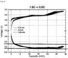
FIG. 3 is a graph showing potentials of positive and negative electrodes and the voltage of a secondary battery in a charging process of the lithium secondary battery according to a first example of the present invention. -
FIG. 4 is a graph showing potentials of positive and negative electrodes and the voltage of a secondary battery in a charging process of a lithium secondary battery according to a first comparative example of the present invention. -
FIG. 5 is a graph showing potentials of positive and negative electrodes and the voltage of a secondary battery in a charging process of a lithium secondary battery according to a second comparative example of the present invention. -
FIG. 6 is a graph showing potentials of positive and negative electrodes and the voltage of a secondary battery in a charging process of a lithium secondary battery according to a third comparative example of the present invention. -
FIG. 7 is a graph showing potentials of positive and negative electrodes and the voltage of a secondary battery in a charging process of a lithium secondary battery according to a fourth comparative example of the present invention. - Hereinafter, the present invention will be described more through some embodiments, but the embodiments merely illustrate the present invention and the scope of the present invention is not limited by the embodiments.
- A slurry was made by adding a positive electrode active material LiCoO (average diameter: 10µm), a conductive agent (Denka black) and a binder (PDVF) with the weight ratio of 97:1:2 to N-methyl pyrrolidone (NMP). The slurry was applied on aluminum foil, dried and rolled by a roll process to thereby make a positive electrode with thickness of 147µm.
- A slurry was made by dissolving an artificial graphite (negative electrode active material), a conductive agent (Denka black), a binder (SBR) and viscosity agent (CMC) with the weight ratio of 96:1:2:1 in water, and the slurry was applied on a copper current collector, dried and rolled by a roll process to thereby make a negative electrode with the thickness of 178µm.
- The separator was respectively inserted between the positive electrode and the negative electrode, which is then wound, compressed and inserted into a pouch type battery case, and carbonate-based electrolyte is injected thereinto to thereby make a lithium secondary battery.
- A slurry was made by adding a positive electrode active material LiCoO (average diameter: 10µm), a conductive agent (Denka black) and a binder (PDVF) with the weight ratio of 97:1:2 to N-methylpyrrolidone (NMP). The slurry was applied on aluminum foil, dried and rolled by a roll process to thereby make a positive electrode with thickness of 107µm (the electrode density is the same as the production example 1).
- A slurry was made by dissolving artificial graphite (negative electrode active material), conductive agent (Denka black), a binder (SBR) and viscosity agent (CMC) with the weight ratio of 96:1:2:1 in water, and the slurry was applied on a copper current collector, dried and rolled by a roll process to thereby make a negative electrode with the thickness of 121µm (the electrode density is the same as the production example 1).
- The separator was respectively inserted between the positive electrode and the negative electrode, which is then wound, compressed and inserted into a pouch type battery case, and carbonate-based electrolyte is injected thereinto to thereby make a lithium secondary battery.
- Lithium secondary batteries made with the same performance as in the production example 1 were charged under the conditions of working example 1 and comparative examples 1 to 6 of Table 1 below, and the lithium secondary battery as in the production example 2 was changed under the condition of the production example 2.
[Table 1] 25°C Charging method Example 1 (Ct=1.2C) (Cascaded CC-CV mode) 2.0C(3.0V∼4.2V)/4.2V-1.5C(4.2V∼4.3V)/4.3V-0.5C(4.3V∼4.4V).4.4V Example 2 (Ct=2.0C) (Cascaded CC-CV mode) 3.3C(3.0V∼4.15V)/4.15V-2.5C(4.15V∼4.25V)/4.25V-0.8C(4.3V∼4.4V).4.4V Comparative example 1 (Ct=1.2C) (Cascaded CC-CV mode) 1.2C(3.0V∼4.2V)/4.2V-0.7C(4.2V∼4.4V)/4.4V Comparative example 2 (Ct=1.2C) (Cascaded CC-CV mode) 1.2C(3.0V∼4.2V)/4.2V-0.5C(4.2V∼4.4V)/4.4V Comparative example 3 (Ct=1.2C) (Cascaded CC-CV mode) 1.5C(3.0V∼4.2V)/4.2V-0.5C(4.2V∼4.4V)/4.4V Comparative example 4 (Ct=1.2C) (Cascaded CC-CV mode) 1.5C(3.0V∼4.2V)/4.2V-0.7C(4.2V∼4.4V)/4.4V Comparative example 5 (Ct=1.2C) (CC-CV mode) 3.0C(3.0V∼4.2V)/4.2V-2.0C(4.2V∼4.3V)/4.3V-1.0C(4.3V∼4.4V).4.4V Comparative example 6 (Ct=1.2C) (CC-CV mode) 1.2C(3.0V-4.4V) *Ct means target C-rate. - When charging with the methods of example 1 and comparative examples 1 to 4 of Table 1, voltage and capacity of the secondary battery and negative electrode and positive electrode until full charge are shown in
FIGS. 3 to 7 . In the graphs, the red lines around the negative electrode potential indicate the maximum and minimum values of the negative electrode potential. - Referring to the drawings, when charging is performed with the charging method of the example 1, the difference between the maximum value and the minimum value in the negative electrode potential flat section during the charging process is equal to or less than 0.15V, which shows a very good flatness. In contrast, when the charging methods of comparative examples 1 to 4 are used, the difference between the maximum value and the minimum value in the negative electrode potential flat section is equal to or greater than 0.15V, and thus it is shown that flatness is low compared to other examples, the difference in the negative electrode potential by sections is large, and the potential may reach the reduction potential of the negative electrode during one time charging period to thereby come to exist a section that the potential drops to a level that lithium dendrite is formed.
- Likewise, when the condition of the present invention is not satisfied, the difference in the electric potential of the negative electrode is large, and thus it is expected that the degradation speed by sections may not be consistent. In contrast, when using the method of the present invention, it is expected that the electric potential of the negative electrode does not reach the lithium dendrite growth potential, and since the flatness by charging sections is good, even when the cycling increases, the degradation speed is consistent, and thus the lifespan characteristic will be good.
- Charging was performed in the condition of the above Table 1 and discharging was performed under 0.7CC condition, and 10 minute rest time was given after charging and discharging, respectively, which was repeated 800 cycles to thereby obtain charged and discharged energies and compare the energies so as to measure the state of charge (SOC) of batteries of examples 1 and 2 and comparative examples 1 to 6 and measure the time until the full charge for one cycle of each. And the result is shown in Table 2 below.
[Table 2] 25°C SOC after 800 cycles (%) Full charge time of 1st cycle (min) Example 1 92 92.7 Example 2 92 76.0 Comparative example 1 82 92.9 Comparative example 2 92 106.5 Comparative example 3 92 101.9 Comparative example 4 60 91.5 Comparative example 5 0 88.2 Comparative example 6 0 86.0 - Referring to the above Table 2, as expected from the experiment example 1, the charging by the charging method according to the present invention shows appropriate charging time and the best lifespan characteristic.
- In contrast, in comparative examples 1 and 4 to 6, the SOC after the cycle is significantly low, and in comparative examples 5 and 6, the charging speed is high but the SOC after 800 cycles becomes almost 0, and thus the battery becomes unusable.
- On the other hand, in comparative examples 2 and 3, the cycle characteristics are similar, but the time until the full charge is about 10 minutes which is slow.
- As cycles are repeated, the negative electrode is degraded and the profile is shifted to the lower side. As shown in the comparative example 6, when CC/CV-charged, the lifespan characteristic significantly drops by reaching Li precipitation are in a high SOC area.
- Likewise, in comparative examples 1 and 4, the charging time may be appropriate by first reaching Li precipitation with high C-rate (0.7C) in the high SOC area, but the lifespan characteristic is inferior. In comparative examples 2 and 3, the potential level is similar to the experiment example in a high SOC example compared to Li precipitation area but C-rate in the low SOC area is low to thereby show a high potential level compared to the experiment example, and thus the total charging speed is low. As in comparative example 5, when using the rate which is different from the rates of the experiment example, the distance with Li precipitation potential by sections is different, thereby rapidly dropping the lifespan.
- Here, the SOC was evaluated by indicating the capacity after 800 cycles compared to the initial capacity as the percentage rate.
- It will be understood by those skilled in the art that various changes in form and details may be made therein without departing from the spirit and scope of the invention as defined by the appended claims.
the ratio of the first C-rate (C1) : the second C-rate (C2) : the third C-rate (C3) satisfies following condition (1):

Claims (10)
- A method of charging a secondary battery, wherein there are charging sections by preset C-rates, and constant current-constant voltage (CC-CV) charging is performed in each of the charging sections,
wherein the charging section comprises:a first charging section in which a CC-charging is performed as a first C-rate (C1) is supplied until the voltage of the secondary battery reaches a first charging cutoff voltage (V1), and a CV-charging is performed as the charging C-rate gradually decreases if reaching the first charging cutoff voltage (V1);a second charging section in which a CC-charging is performed as a second C-rate (C2) is supplied until the voltage of the secondary battery reaches a second charging cutoff voltage (V2), and a CV-charging is performed as the charging C-rate gradually decreases if reaching the second charging cutoff voltage (V2); anda third charging section in which a CC-charging is performed as a third C-rate (C3) is supplied until the voltage of the secondary battery reaches a third charging cutoff voltage (V3), and a CV-charging is performed as the charging C-rate gradually decreases if reaching the third charging cutoff voltage (V3),wherein the charging cutoff voltage satisfies the V1 = n-(0.25∼0.15), V2 = n-(0.2-0.1), and V3 = n (here, 'n' is an electric potential at the full charge of the secondary battery), and V1 < V2 < V3, and
wherein the ratio of the first C-rate (C1) : the second C-rate (C2) : the third C-rate (C3) satisfies following condition (1):
- The method of claim 1, wherein the charge C-rate having reached the charge cutoff voltage at each charge section gradually decreases to the preset C-rate of the next charge section
- The method of claim 1, wherein on the basis of the target C-rate (Ct) having been set based thereon, the first C-rate (C1) is between 1.6Ct and 1.7Ct, the second C-rate (C2) may be between 1.2Ct and 1.3Ct, the third C-rate (C3) may be between 0.4Ct and 0.5Ct.
- The method of claim 3, wherein the target C-rate Ct set to correspond to the constant current-constant voltage (CC-CV) charge of step 1 is determined by the loading amount of the negative electrode of the secondary battery.
- The method of claim 4, wherein the target C-rate (Ct) is in inverse proportion to the amount of loading of the negative electrode.
- The method of claim 5, wherein the target C-rate (Ct) is in inverse proportion to the amount of loading of the negative electrode exponentially.
- The method of claim 1, wherein the secondary battery is a lithium ion battery having embedded therein an electrode assembly including a positive electrode, a negative electrode, and a separator interposed between the positive electrode and the negative electrode in a battery case in a state of being impregnated with an electrolytic solution.
- The method of claim 7, wherein the negative electrode comprises graphite carbon as a negative electrode active material.
- The method of claim 1, wherein the difference between the maximum value and the minimum value of the negative electrode flat section during the charging of the secondary battery may be maintained at less than 0.15V.
- The method of claim 1, wherein the potential of the negative electrode during one time charge of the secondary battery does not reach the lithium dendrite growth potential in the entire region.
Applications Claiming Priority (2)
| Application Number | Priority Date | Filing Date | Title |
|---|---|---|---|
| KR1020170030314A KR102254353B1 (en) | 2017-03-10 | 2017-03-10 | Charging Method of Secondary Battery |
| PCT/KR2018/002799 WO2018164523A1 (en) | 2017-03-10 | 2018-03-09 | Method for charging secondary battery |
Publications (3)
| Publication Number | Publication Date |
|---|---|
| EP3518381A1 true EP3518381A1 (en) | 2019-07-31 |
| EP3518381A4 EP3518381A4 (en) | 2019-12-04 |
| EP3518381B1 EP3518381B1 (en) | 2021-06-02 |
Family
ID=63448763
Family Applications (1)
| Application Number | Title | Priority Date | Filing Date |
|---|---|---|---|
| EP18764928.0A Active EP3518381B1 (en) | 2017-03-10 | 2018-03-09 | Method for charging secondary battery |
Country Status (5)
| Country | Link |
|---|---|
| US (1) | US11056901B2 (en) |
| EP (1) | EP3518381B1 (en) |
| KR (1) | KR102254353B1 (en) |
| CN (1) | CN109923753B (en) |
| WO (1) | WO2018164523A1 (en) |
Families Citing this family (16)
| Publication number | Priority date | Publication date | Assignee | Title |
|---|---|---|---|---|
| JP6968774B2 (en) * | 2018-09-26 | 2021-11-17 | 本田技研工業株式会社 | Lithium-ion battery control device, lithium-ion battery control method, and program |
| KR102800822B1 (en) | 2019-02-14 | 2025-04-29 | 삼성전자주식회사 | Method to charge battery and electronic device applying the method |
| CN112448054B (en) * | 2019-08-30 | 2023-02-17 | 北京小米移动软件有限公司 | Charging method and device of mobile terminal, terminal and storage medium |
| DE102019216015A1 (en) * | 2019-10-17 | 2021-04-22 | Robert Bosch Gmbh | Method of adjusting an anode overvoltage of a lithium-ion battery, method of improving a capacity aging condition of the lithium-ion battery |
| CN111211595B (en) * | 2020-01-14 | 2021-11-09 | 北京小米移动软件有限公司 | Charging method and device, electronic equipment and storage medium |
| KR102971775B1 (en) * | 2020-06-18 | 2026-05-29 | 주식회사 엘지에너지솔루션 | Battery management system, battery management method, battery pakc, and electric vehicle |
| WO2022027223A1 (en) * | 2020-08-04 | 2022-02-10 | 宁德新能源科技有限公司 | Electronic device, charging method for electrochemical device, terminal and storage medium |
| CN112383102B (en) * | 2020-10-28 | 2024-03-19 | 欣旺达动力科技股份有限公司 | Battery charging methods, electronic devices and storage media |
| CN116169733A (en) * | 2021-11-25 | 2023-05-26 | 中兴通讯股份有限公司 | Charging control method, system, terminal device, charger and storage medium |
| CN118057650A (en) * | 2022-11-18 | 2024-05-21 | 广东华芯智源科技有限公司 | A charging method and system for delaying the aging speed of lithium-ion batteries |
| CN116316978B (en) * | 2023-03-17 | 2026-05-01 | 珠海冠宇电池股份有限公司 | Battery charging control method and device, electronic equipment and storage medium |
| KR102839921B1 (en) * | 2023-08-31 | 2025-07-28 | 주식회사 엘지에너지솔루션 | Apparatus and method for diagnosing battery |
| KR102836737B1 (en) * | 2023-08-31 | 2025-07-18 | 주식회사 엘지에너지솔루션 | Apparatus and method for diagnosing battery |
| KR102825294B1 (en) * | 2023-08-31 | 2025-06-25 | 주식회사 엘지에너지솔루션 | Apparatus and method for diagnosing battery |
| KR102896754B1 (en) * | 2023-08-31 | 2025-12-04 | 주식회사 엘지에너지솔루션 | Apparatus and method for diagnosing battery |
| FR3169401A1 (en) * | 2024-12-06 | 2026-06-12 | Stellantis Auto Sas | METHOD FOR CHARGING A BATTERY BY A CHARGING PROFILE COMPRISING CURRENT LEVELS |
Family Cites Families (50)
| Publication number | Priority date | Publication date | Assignee | Title |
|---|---|---|---|---|
| JPH1197074A (en) | 1997-09-19 | 1999-04-09 | Zip Charge:Kk | Charging method and charging device |
| US5994878A (en) | 1997-09-30 | 1999-11-30 | Chartec Laboratories A/S | Method and apparatus for charging a rechargeable battery |
| JP3908459B2 (en) * | 2000-12-22 | 2007-04-25 | 三洋電機株式会社 | Nonaqueous electrolyte secondary battery |
| US6916579B2 (en) * | 2002-05-30 | 2005-07-12 | Enerl Battery Company | Cathode material for lithium battery |
| JP5069403B2 (en) * | 2002-12-23 | 2012-11-07 | エー123 システムズ, インコーポレイテッド | High energy density High power density electrochemical cell |
| US8617745B2 (en) * | 2004-02-06 | 2013-12-31 | A123 Systems Llc | Lithium secondary cell with high charge and discharge rate capability and low impedance growth |
| EP2043182B1 (en) * | 2006-07-19 | 2017-05-31 | Nippon Carbon Co., Ltd. | Negative electrode active material and negative electrode for lithium ion rechargeable battery |
| JP2008059999A (en) * | 2006-09-01 | 2008-03-13 | Sony Corp | Negative electrode and nonaqueous electrolyte secondary battery using the same |
| US20080081258A1 (en) * | 2006-09-28 | 2008-04-03 | Korea Electro Technology Research Institute | Carbon-coated composite material, manufacturing method thereof, positive electrode active material, and lithium secondary battery comprising the same |
| US8013577B2 (en) * | 2006-12-04 | 2011-09-06 | Panasonic Corporation | Charging system, charging apparatus and battery pack |
| JP5318356B2 (en) * | 2007-02-23 | 2013-10-16 | 三洋電機株式会社 | Nonaqueous electrolyte secondary battery |
| CN101636872A (en) * | 2007-03-07 | 2010-01-27 | 松下电器产业株式会社 | Quick charging method of lithium based secondary battery and electronic apparatus employing it |
| JP4435194B2 (en) * | 2007-03-27 | 2010-03-17 | 株式会社東芝 | Non-aqueous electrolyte battery, battery pack and automobile |
| CN101071887A (en) | 2007-05-20 | 2007-11-14 | 张家港市华为电子有限公司 | Lead-acid battery charging method |
| TWI343141B (en) * | 2007-06-14 | 2011-06-01 | Compal Electronics Inc | Method for charging battery module in multiple stages |
| JP5247196B2 (en) * | 2008-03-19 | 2013-07-24 | 三洋電機株式会社 | Nonaqueous electrolyte secondary battery |
| US8624560B2 (en) | 2008-04-11 | 2014-01-07 | Apple Inc. | Controlling battery charging based on current, voltage and temperature |
| WO2009150773A1 (en) * | 2008-06-12 | 2009-12-17 | パナソニック株式会社 | Charging method and discharging method of lithium ion secondary battery |
| WO2010051540A1 (en) * | 2008-10-31 | 2010-05-06 | The Curators Of The University Of Missouri | Convection battery configuration for connective carbon matrix electrode |
| WO2010073930A1 (en) * | 2008-12-26 | 2010-07-01 | Jmエナジー株式会社 | Wound-type accumulator |
| EP2437331B1 (en) * | 2009-05-26 | 2016-10-12 | LG Chem, Ltd. | Lithium secondary battery with high energy density |
| KR101096936B1 (en) * | 2009-07-23 | 2011-12-22 | 지에스칼텍스 주식회사 | Negative active material for rechargeable lithium battery, method of manufacturing the same and rechargeable lithium battery having the same |
| US20110037439A1 (en) * | 2009-08-17 | 2011-02-17 | Apple Inc. | Increasing energy density in rechargeable lithium battery cells |
| US8816648B2 (en) * | 2009-08-17 | 2014-08-26 | Apple Inc. | Modulated, temperature-based multi-CC-CV charging technique for Li-ion/Li-polymer batteries |
| KR20110024707A (en) * | 2009-09-03 | 2011-03-09 | 주식회사 엘지화학 | Charging method of lithium secondary battery |
| US9893377B2 (en) * | 2009-09-25 | 2018-02-13 | Kabushiki Kaisha Toshiba | Nonaqueous electrolyte battery, battery pack and vehicle |
| JP4768090B2 (en) * | 2009-11-20 | 2011-09-07 | パナソニック株式会社 | Charge control circuit, battery pack, and charging system |
| JP4818491B2 (en) * | 2009-12-14 | 2011-11-16 | パナソニック株式会社 | Non-aqueous electrolyte secondary battery charging method and battery pack |
| US8643342B2 (en) | 2009-12-31 | 2014-02-04 | Tesla Motors, Inc. | Fast charging with negative ramped current profile |
| JP5594583B2 (en) * | 2010-07-30 | 2014-09-24 | 独立行政法人産業技術総合研究所 | Method for manufacturing reference electrode |
| KR101723998B1 (en) * | 2011-05-06 | 2017-04-06 | 삼성전자주식회사 | Apparatus and method for controlling charging currnet in device using recargable battery |
| EP3057170B1 (en) * | 2011-06-29 | 2017-04-26 | Nitto Denko Corporation | Nonaqueous electrolyte secondary battery and cathode sheet therefor |
| US9368995B2 (en) | 2011-09-30 | 2016-06-14 | Panasonic Intellectual Property Management Co., Ltd. | Lithium ion battery charging method and battery-equipped device |
| WO2013183952A1 (en) | 2012-06-07 | 2013-12-12 | 주식회사 엘지화학 | Method for charging secondary battery |
| JP2014010018A (en) | 2012-06-28 | 2014-01-20 | Seiko Epson Corp | Handler and inspection device |
| US9081068B2 (en) * | 2012-09-18 | 2015-07-14 | Apple Inc. | Method and apparatus for determining a capacity of a battery |
| US8993159B2 (en) * | 2012-12-13 | 2015-03-31 | 24M Technologies, Inc. | Semi-solid electrodes having high rate capability |
| US20140266068A1 (en) * | 2013-03-14 | 2014-09-18 | Evgentech, Inc. | Pulse battery charger methods and systems for improved charging of lithium ion batteries |
| US9559543B2 (en) * | 2013-07-19 | 2017-01-31 | Apple Inc. | Adaptive effective C-rate charging of batteries |
| KR101494166B1 (en) | 2013-09-17 | 2015-02-17 | 한국수력원자력 주식회사 | System for Leakage Rate of Containment Building |
| KR102248599B1 (en) | 2014-05-20 | 2021-05-06 | 삼성에스디아이 주식회사 | Mehtod for charging a battert and battery management system thereof |
| US9882196B2 (en) * | 2014-07-02 | 2018-01-30 | Pellion Technologies, Inc. | Multi-electrode electrochemical cell and method of making the same |
| CN105322245B (en) * | 2014-07-31 | 2018-01-09 | 中信国安盟固利动力科技有限公司 | A kind of charging method for improving lithium ion battery charge efficiency |
| KR102273766B1 (en) | 2014-08-26 | 2021-07-06 | 삼성에스디아이 주식회사 | Battery charging method and battery pack using the method |
| US9509162B2 (en) * | 2015-04-30 | 2016-11-29 | Active-Semi, Inc. | Single-stage AC-to-DC switching converter that directly charges a battery requiring a multi-state charging profile |
| KR101985812B1 (en) * | 2015-08-18 | 2019-06-04 | 주식회사 엘지화학 | Charging limit evaluation method of battery, method and apparatus for fast charging using the same |
| CN109075583A (en) * | 2016-03-31 | 2018-12-21 | 技领半导体股份有限公司 | Quick charge device and method |
| US10014706B2 (en) | 2016-05-23 | 2018-07-03 | Nxp B.V. | Model-based fast-charging method based on lithium surface concentration |
| KR102730913B1 (en) | 2017-02-07 | 2024-11-14 | 삼성전자주식회사 | Method and apparatus for charging battery |
| US11189828B2 (en) * | 2019-02-27 | 2021-11-30 | Battelle Memorial Institute | Lithium metal pouch cells and methods of making the same |
-
2017
- 2017-03-10 KR KR1020170030314A patent/KR102254353B1/en active Active
-
2018
- 2018-03-09 US US16/339,549 patent/US11056901B2/en active Active
- 2018-03-09 CN CN201880004152.5A patent/CN109923753B/en active Active
- 2018-03-09 EP EP18764928.0A patent/EP3518381B1/en active Active
- 2018-03-09 WO PCT/KR2018/002799 patent/WO2018164523A1/en not_active Ceased
Also Published As
| Publication number | Publication date |
|---|---|
| WO2018164523A1 (en) | 2018-09-13 |
| EP3518381B1 (en) | 2021-06-02 |
| CN109923753B (en) | 2022-12-06 |
| KR20180103412A (en) | 2018-09-19 |
| US20190237975A1 (en) | 2019-08-01 |
| US11056901B2 (en) | 2021-07-06 |
| KR102254353B1 (en) | 2021-05-21 |
| EP3518381A4 (en) | 2019-12-04 |
| CN109923753A (en) | 2019-06-21 |
Similar Documents
| Publication | Publication Date | Title |
|---|---|---|
| EP3518381B1 (en) | Method for charging secondary battery | |
| US11876191B2 (en) | Method for activating secondary battery | |
| KR101788232B1 (en) | Electrode with Improved Adhesion Property for Lithium Secondary Battery | |
| KR101783445B1 (en) | Multilayer-Structured Electrode and Lithium Secondary Battery Comprising The Same | |
| US11936037B2 (en) | Multi-layered anode containing silicon-based compound and lithium secondary battery including the same | |
| KR101625822B1 (en) | Mixture for Cathode for Secondary Battery having irreversible Additives | |
| EP3561918A1 (en) | Pre-lithiation method for anode for secondary battery | |
| KR101540618B1 (en) | Electrode for Secondary Battery and Method of Preparing the Same | |
| KR102120271B1 (en) | Positive Electrode Active Material Comprising High-voltage Lithium Cobalt Oxide Having Doping element for Lithium Secondary Battery and Method of Manufacturing the Same | |
| KR102147364B1 (en) | Metal Doped-Positive Active Material for High Voltage | |
| EP3518323B1 (en) | Method for manufacturing high-loading electrode | |
| CN114730866A (en) | Negative electrode for lithium metal battery, method for manufacturing same, and lithium metal battery comprising same | |
| KR20160050283A (en) | Preparation Method of Multilayer Electrode for Secondary Battery | |
| KR20170040766A (en) | Method for Preparing Electrode for Secondary Battery through Control of Pressing Velocity and Electrode Prepared by the Same | |
| KR101684338B1 (en) | Electrode Material for Secondary Battery and Lithium Secondary Battery Comprising the Same | |
| KR101499588B1 (en) | Electrode for Secondary Battery and Manufacturing Method thereof | |
| KR101991057B1 (en) | Lithium secondary battery and operating method thereof | |
| KR101608635B1 (en) | Anode Electrodes for Secondary Battery having High Capacity | |
| KR20210029479A (en) | Pre-lithiation appratus | |
| EP3826098B1 (en) | Method for recovering lithium battery cell by heat treatment and method for manufacturing lithium battery cell comprising the same | |
| KR101822991B1 (en) | The Method for Preparing Lithium Secondary Battery and the Lithium Secondary Battery Prepared by Using the Same | |
| KR101656076B1 (en) | Electrode Material Improved Energy Density and Lithium Secondary Battery Comprising the Same | |
| KR101159103B1 (en) | Anode Mix Containing Anode Additive for Improving Efficiency of Electrode | |
| KR20200023730A (en) | Positive electrode material for lithium metal battery and manufacturing method thereof |
Legal Events
| Date | Code | Title | Description |
|---|---|---|---|
| STAA | Information on the status of an ep patent application or granted ep patent |
Free format text: STATUS: THE INTERNATIONAL PUBLICATION HAS BEEN MADE |
|
| PUAI | Public reference made under article 153(3) epc to a published international application that has entered the european phase |
Free format text: ORIGINAL CODE: 0009012 |
|
| STAA | Information on the status of an ep patent application or granted ep patent |
Free format text: STATUS: REQUEST FOR EXAMINATION WAS MADE |
|
| 17P | Request for examination filed |
Effective date: 20190426 |
|
| AK | Designated contracting states |
Kind code of ref document: A1 Designated state(s): AL AT BE BG CH CY CZ DE DK EE ES FI FR GB GR HR HU IE IS IT LI LT LU LV MC MK MT NL NO PL PT RO RS SE SI SK SM TR |
|
| AX | Request for extension of the european patent |
Extension state: BA ME |
|
| A4 | Supplementary search report drawn up and despatched |
Effective date: 20191105 |
|
| RIC1 | Information provided on ipc code assigned before grant |
Ipc: H01M 4/583 20100101ALN20191029BHEP Ipc: H02J 7/04 20060101AFI20191029BHEP Ipc: H01M 10/44 20060101ALI20191029BHEP Ipc: H01M 10/052 20100101ALI20191029BHEP |
|
| DAV | Request for validation of the european patent (deleted) | ||
| DAX | Request for extension of the european patent (deleted) | ||
| RIC1 | Information provided on ipc code assigned before grant |
Ipc: H01M 10/0525 20100101ALN20200616BHEP Ipc: H01M 4/583 20100101ALN20200616BHEP Ipc: H01M 10/44 20060101ALI20200616BHEP Ipc: H02J 7/04 20060101AFI20200616BHEP Ipc: H01M 10/052 20100101ALI20200616BHEP |
|
| RIC1 | Information provided on ipc code assigned before grant |
Ipc: H01M 10/0525 20100101ALN20200716BHEP Ipc: H01M 4/583 20100101ALN20200716BHEP Ipc: H02J 7/04 20060101AFI20200716BHEP Ipc: H01M 10/44 20060101ALI20200716BHEP Ipc: H01M 10/052 20100101ALI20200716BHEP |
|
| GRAP | Despatch of communication of intention to grant a patent |
Free format text: ORIGINAL CODE: EPIDOSNIGR1 |
|
| STAA | Information on the status of an ep patent application or granted ep patent |
Free format text: STATUS: GRANT OF PATENT IS INTENDED |
|
| RIC1 | Information provided on ipc code assigned before grant |
Ipc: H01M 10/0525 20100101ALN20200901BHEP Ipc: H02J 7/04 20060101AFI20200901BHEP Ipc: H01M 10/44 20060101ALI20200901BHEP Ipc: H01M 4/583 20100101ALN20200901BHEP Ipc: H01M 10/052 20100101ALI20200901BHEP |
|
| INTG | Intention to grant announced |
Effective date: 20200921 |
|
| GRAJ | Information related to disapproval of communication of intention to grant by the applicant or resumption of examination proceedings by the epo deleted |
Free format text: ORIGINAL CODE: EPIDOSDIGR1 |
|
| REG | Reference to a national code |
Ref country code: DE Ref legal event code: R079 Ref document number: 602018018125 Country of ref document: DE Free format text: PREVIOUS MAIN CLASS: H02J0007000000 Ipc: H02J0007040000 |
|
| STAA | Information on the status of an ep patent application or granted ep patent |
Free format text: STATUS: REQUEST FOR EXAMINATION WAS MADE |
|
| GRAP | Despatch of communication of intention to grant a patent |
Free format text: ORIGINAL CODE: EPIDOSNIGR1 |
|
| STAA | Information on the status of an ep patent application or granted ep patent |
Free format text: STATUS: GRANT OF PATENT IS INTENDED |
|
| INTC | Intention to grant announced (deleted) | ||
| RIC1 | Information provided on ipc code assigned before grant |
Ipc: H01M 4/583 20100101ALN20201123BHEP Ipc: H02J 7/04 20060101AFI20201123BHEP Ipc: H01M 10/0525 20100101ALN20201123BHEP Ipc: H01M 10/052 20100101ALI20201123BHEP Ipc: H01M 10/44 20060101ALI20201123BHEP |
|
| INTG | Intention to grant announced |
Effective date: 20201209 |
|
| GRAS | Grant fee paid |
Free format text: ORIGINAL CODE: EPIDOSNIGR3 |
|
| GRAA | (expected) grant |
Free format text: ORIGINAL CODE: 0009210 |
|
| STAA | Information on the status of an ep patent application or granted ep patent |
Free format text: STATUS: THE PATENT HAS BEEN GRANTED |
|
| REG | Reference to a national code |
Ref country code: CH Ref legal event code: EP |
|
| AK | Designated contracting states |
Kind code of ref document: B1 Designated state(s): AL AT BE BG CH CY CZ DE DK EE ES FI FR GB GR HR HU IE IS IT LI LT LU LV MC MK MT NL NO PL PT RO RS SE SI SK SM TR |
|
| REG | Reference to a national code |
Ref country code: GB Ref legal event code: FG4D |
|
| REG | Reference to a national code |
Ref country code: AT Ref legal event code: REF Ref document number: 1399343 Country of ref document: AT Kind code of ref document: T Effective date: 20210615 |
|
| REG | Reference to a national code |
Ref country code: IE Ref legal event code: FG4D |
|
| REG | Reference to a national code |
Ref country code: DE Ref legal event code: R096 Ref document number: 602018018125 Country of ref document: DE |
|
| REG | Reference to a national code |
Ref country code: LT Ref legal event code: MG9D |
|
| PG25 | Lapsed in a contracting state [announced via postgrant information from national office to epo] |
Ref country code: BG Free format text: LAPSE BECAUSE OF FAILURE TO SUBMIT A TRANSLATION OF THE DESCRIPTION OR TO PAY THE FEE WITHIN THE PRESCRIBED TIME-LIMIT Effective date: 20210902 Ref country code: FI Free format text: LAPSE BECAUSE OF FAILURE TO SUBMIT A TRANSLATION OF THE DESCRIPTION OR TO PAY THE FEE WITHIN THE PRESCRIBED TIME-LIMIT Effective date: 20210602 Ref country code: HR Free format text: LAPSE BECAUSE OF FAILURE TO SUBMIT A TRANSLATION OF THE DESCRIPTION OR TO PAY THE FEE WITHIN THE PRESCRIBED TIME-LIMIT Effective date: 20210602 Ref country code: LT Free format text: LAPSE BECAUSE OF FAILURE TO SUBMIT A TRANSLATION OF THE DESCRIPTION OR TO PAY THE FEE WITHIN THE PRESCRIBED TIME-LIMIT Effective date: 20210602 |
|
| REG | Reference to a national code |
Ref country code: NL Ref legal event code: MP Effective date: 20210602 |
|
| REG | Reference to a national code |
Ref country code: AT Ref legal event code: MK05 Ref document number: 1399343 Country of ref document: AT Kind code of ref document: T Effective date: 20210602 |
|
| PG25 | Lapsed in a contracting state [announced via postgrant information from national office to epo] |
Ref country code: GR Free format text: LAPSE BECAUSE OF FAILURE TO SUBMIT A TRANSLATION OF THE DESCRIPTION OR TO PAY THE FEE WITHIN THE PRESCRIBED TIME-LIMIT Effective date: 20210903 Ref country code: LV Free format text: LAPSE BECAUSE OF FAILURE TO SUBMIT A TRANSLATION OF THE DESCRIPTION OR TO PAY THE FEE WITHIN THE PRESCRIBED TIME-LIMIT Effective date: 20210602 Ref country code: NO Free format text: LAPSE BECAUSE OF FAILURE TO SUBMIT A TRANSLATION OF THE DESCRIPTION OR TO PAY THE FEE WITHIN THE PRESCRIBED TIME-LIMIT Effective date: 20210902 Ref country code: PL Free format text: LAPSE BECAUSE OF FAILURE TO SUBMIT A TRANSLATION OF THE DESCRIPTION OR TO PAY THE FEE WITHIN THE PRESCRIBED TIME-LIMIT Effective date: 20210602 Ref country code: RS Free format text: LAPSE BECAUSE OF FAILURE TO SUBMIT A TRANSLATION OF THE DESCRIPTION OR TO PAY THE FEE WITHIN THE PRESCRIBED TIME-LIMIT Effective date: 20210602 Ref country code: SE Free format text: LAPSE BECAUSE OF FAILURE TO SUBMIT A TRANSLATION OF THE DESCRIPTION OR TO PAY THE FEE WITHIN THE PRESCRIBED TIME-LIMIT Effective date: 20210602 |
|
| RAP2 | Party data changed (patent owner data changed or rights of a patent transferred) |
Owner name: LG ENERGY SOLUTION LTD. |
|
| PG25 | Lapsed in a contracting state [announced via postgrant information from national office to epo] |
Ref country code: EE Free format text: LAPSE BECAUSE OF FAILURE TO SUBMIT A TRANSLATION OF THE DESCRIPTION OR TO PAY THE FEE WITHIN THE PRESCRIBED TIME-LIMIT Effective date: 20210602 Ref country code: ES Free format text: LAPSE BECAUSE OF FAILURE TO SUBMIT A TRANSLATION OF THE DESCRIPTION OR TO PAY THE FEE WITHIN THE PRESCRIBED TIME-LIMIT Effective date: 20210602 Ref country code: SK Free format text: LAPSE BECAUSE OF FAILURE TO SUBMIT A TRANSLATION OF THE DESCRIPTION OR TO PAY THE FEE WITHIN THE PRESCRIBED TIME-LIMIT Effective date: 20210602 Ref country code: RO Free format text: LAPSE BECAUSE OF FAILURE TO SUBMIT A TRANSLATION OF THE DESCRIPTION OR TO PAY THE FEE WITHIN THE PRESCRIBED TIME-LIMIT Effective date: 20210602 Ref country code: PT Free format text: LAPSE BECAUSE OF FAILURE TO SUBMIT A TRANSLATION OF THE DESCRIPTION OR TO PAY THE FEE WITHIN THE PRESCRIBED TIME-LIMIT Effective date: 20211004 Ref country code: NL Free format text: LAPSE BECAUSE OF FAILURE TO SUBMIT A TRANSLATION OF THE DESCRIPTION OR TO PAY THE FEE WITHIN THE PRESCRIBED TIME-LIMIT Effective date: 20210602 Ref country code: SM Free format text: LAPSE BECAUSE OF FAILURE TO SUBMIT A TRANSLATION OF THE DESCRIPTION OR TO PAY THE FEE WITHIN THE PRESCRIBED TIME-LIMIT Effective date: 20210602 Ref country code: AT Free format text: LAPSE BECAUSE OF FAILURE TO SUBMIT A TRANSLATION OF THE DESCRIPTION OR TO PAY THE FEE WITHIN THE PRESCRIBED TIME-LIMIT Effective date: 20210602 Ref country code: CZ Free format text: LAPSE BECAUSE OF FAILURE TO SUBMIT A TRANSLATION OF THE DESCRIPTION OR TO PAY THE FEE WITHIN THE PRESCRIBED TIME-LIMIT Effective date: 20210602 |
|
| REG | Reference to a national code |
Ref country code: DE Ref legal event code: R097 Ref document number: 602018018125 Country of ref document: DE |
|
| RAP4 | Party data changed (patent owner data changed or rights of a patent transferred) |
Owner name: LG ENERGY SOLUTION, LTD. |
|
| PLBE | No opposition filed within time limit |
Free format text: ORIGINAL CODE: 0009261 |
|
| STAA | Information on the status of an ep patent application or granted ep patent |
Free format text: STATUS: NO OPPOSITION FILED WITHIN TIME LIMIT |
|
| PG25 | Lapsed in a contracting state [announced via postgrant information from national office to epo] |
Ref country code: DK Free format text: LAPSE BECAUSE OF FAILURE TO SUBMIT A TRANSLATION OF THE DESCRIPTION OR TO PAY THE FEE WITHIN THE PRESCRIBED TIME-LIMIT Effective date: 20210602 |
|
| 26N | No opposition filed |
Effective date: 20220303 |
|
| PG25 | Lapsed in a contracting state [announced via postgrant information from national office to epo] |
Ref country code: AL Free format text: LAPSE BECAUSE OF FAILURE TO SUBMIT A TRANSLATION OF THE DESCRIPTION OR TO PAY THE FEE WITHIN THE PRESCRIBED TIME-LIMIT Effective date: 20210602 |
|
| PG25 | Lapsed in a contracting state [announced via postgrant information from national office to epo] |
Ref country code: IT Free format text: LAPSE BECAUSE OF FAILURE TO SUBMIT A TRANSLATION OF THE DESCRIPTION OR TO PAY THE FEE WITHIN THE PRESCRIBED TIME-LIMIT Effective date: 20210602 |
|
| PG25 | Lapsed in a contracting state [announced via postgrant information from national office to epo] |
Ref country code: MC Free format text: LAPSE BECAUSE OF FAILURE TO SUBMIT A TRANSLATION OF THE DESCRIPTION OR TO PAY THE FEE WITHIN THE PRESCRIBED TIME-LIMIT Effective date: 20210602 |
|
| REG | Reference to a national code |
Ref country code: CH Ref legal event code: PL |
|
| REG | Reference to a national code |
Ref country code: BE Ref legal event code: MM Effective date: 20220331 |
|
| PG25 | Lapsed in a contracting state [announced via postgrant information from national office to epo] |
Ref country code: LU Free format text: LAPSE BECAUSE OF NON-PAYMENT OF DUE FEES Effective date: 20220309 Ref country code: LI Free format text: LAPSE BECAUSE OF NON-PAYMENT OF DUE FEES Effective date: 20220331 Ref country code: IE Free format text: LAPSE BECAUSE OF NON-PAYMENT OF DUE FEES Effective date: 20220309 Ref country code: CH Free format text: LAPSE BECAUSE OF NON-PAYMENT OF DUE FEES Effective date: 20220331 |
|
| PG25 | Lapsed in a contracting state [announced via postgrant information from national office to epo] |
Ref country code: BE Free format text: LAPSE BECAUSE OF NON-PAYMENT OF DUE FEES Effective date: 20220331 |
|
| REG | Reference to a national code |
Ref country code: DE Ref legal event code: R081 Ref document number: 602018018125 Country of ref document: DE Owner name: LG ENERGY SOLUTION, LTD., KR Free format text: FORMER OWNER: LG CHEM, LTD., SEOUL, KR |
|
| P01 | Opt-out of the competence of the unified patent court (upc) registered |
Effective date: 20230512 |
|
| REG | Reference to a national code |
Ref country code: GB Ref legal event code: 732E Free format text: REGISTERED BETWEEN 20230901 AND 20230906 |
|
| PG25 | Lapsed in a contracting state [announced via postgrant information from national office to epo] |
Ref country code: MK Free format text: LAPSE BECAUSE OF FAILURE TO SUBMIT A TRANSLATION OF THE DESCRIPTION OR TO PAY THE FEE WITHIN THE PRESCRIBED TIME-LIMIT Effective date: 20210602 Ref country code: CY Free format text: LAPSE BECAUSE OF FAILURE TO SUBMIT A TRANSLATION OF THE DESCRIPTION OR TO PAY THE FEE WITHIN THE PRESCRIBED TIME-LIMIT Effective date: 20210602 |
|
| PG25 | Lapsed in a contracting state [announced via postgrant information from national office to epo] |
Ref country code: HU Free format text: LAPSE BECAUSE OF FAILURE TO SUBMIT A TRANSLATION OF THE DESCRIPTION OR TO PAY THE FEE WITHIN THE PRESCRIBED TIME-LIMIT; INVALID AB INITIO Effective date: 20180309 |
|
| PG25 | Lapsed in a contracting state [announced via postgrant information from national office to epo] |
Ref country code: TR Free format text: LAPSE BECAUSE OF FAILURE TO SUBMIT A TRANSLATION OF THE DESCRIPTION OR TO PAY THE FEE WITHIN THE PRESCRIBED TIME-LIMIT Effective date: 20210602 |
|
| PG25 | Lapsed in a contracting state [announced via postgrant information from national office to epo] |
Ref country code: MT Free format text: LAPSE BECAUSE OF FAILURE TO SUBMIT A TRANSLATION OF THE DESCRIPTION OR TO PAY THE FEE WITHIN THE PRESCRIBED TIME-LIMIT Effective date: 20210602 |
|
| PGFP | Annual fee paid to national office [announced via postgrant information from national office to epo] |
Ref country code: GB Payment date: 20260224 Year of fee payment: 9 |
|
| PGFP | Annual fee paid to national office [announced via postgrant information from national office to epo] |
Ref country code: DE Payment date: 20260220 Year of fee payment: 9 |
|
| PGFP | Annual fee paid to national office [announced via postgrant information from national office to epo] |
Ref country code: FR Payment date: 20260224 Year of fee payment: 9 |