EP3518353A1 - Method for producing a modularly configurable coaxial plug - Google Patents
Method for producing a modularly configurable coaxial plug Download PDFInfo
- Publication number
- EP3518353A1 EP3518353A1 EP19154019.4A EP19154019A EP3518353A1 EP 3518353 A1 EP3518353 A1 EP 3518353A1 EP 19154019 A EP19154019 A EP 19154019A EP 3518353 A1 EP3518353 A1 EP 3518353A1
- Authority
- EP
- European Patent Office
- Prior art keywords
- section
- plug
- cable
- interface section
- contact
- Prior art date
- Legal status (The legal status is an assumption and is not a legal conclusion. Google has not performed a legal analysis and makes no representation as to the accuracy of the status listed.)
- Pending
Links
Images


Classifications
-
- H—ELECTRICITY
- H01—ELECTRIC ELEMENTS
- H01R—ELECTRICALLY-CONDUCTIVE CONNECTIONS; STRUCTURAL ASSOCIATIONS OF A PLURALITY OF MUTUALLY-INSULATED ELECTRICAL CONNECTING ELEMENTS; COUPLING DEVICES; CURRENT COLLECTORS
- H01R24/00—Two-part coupling devices, or either of their cooperating parts, characterised by their overall structure
- H01R24/38—Two-part coupling devices, or either of their cooperating parts, characterised by their overall structure having concentrically or coaxially arranged contacts
- H01R24/40—Two-part coupling devices, or either of their cooperating parts, characterised by their overall structure having concentrically or coaxially arranged contacts specially adapted for high frequency
- H01R24/52—Two-part coupling devices, or either of their cooperating parts, characterised by their overall structure having concentrically or coaxially arranged contacts specially adapted for high frequency mounted in or to a panel or structure
-
- H—ELECTRICITY
- H01—ELECTRIC ELEMENTS
- H01R—ELECTRICALLY-CONDUCTIVE CONNECTIONS; STRUCTURAL ASSOCIATIONS OF A PLURALITY OF MUTUALLY-INSULATED ELECTRICAL CONNECTING ELEMENTS; COUPLING DEVICES; CURRENT COLLECTORS
- H01R24/00—Two-part coupling devices, or either of their cooperating parts, characterised by their overall structure
- H01R24/38—Two-part coupling devices, or either of their cooperating parts, characterised by their overall structure having concentrically or coaxially arranged contacts
- H01R24/40—Two-part coupling devices, or either of their cooperating parts, characterised by their overall structure having concentrically or coaxially arranged contacts specially adapted for high frequency
- H01R24/54—Intermediate parts, e.g. adapters, splitters or elbows
- H01R24/542—Adapters
-
- H—ELECTRICITY
- H01—ELECTRIC ELEMENTS
- H01R—ELECTRICALLY-CONDUCTIVE CONNECTIONS; STRUCTURAL ASSOCIATIONS OF A PLURALITY OF MUTUALLY-INSULATED ELECTRICAL CONNECTING ELEMENTS; COUPLING DEVICES; CURRENT COLLECTORS
- H01R13/00—Details of coupling devices of the kinds covered by groups H01R12/70 or H01R24/00 - H01R33/00
- H01R13/62—Means for facilitating engagement or disengagement of coupling parts or for holding them in engagement
- H01R13/627—Snap or like fastening
-
- H—ELECTRICITY
- H01—ELECTRIC ELEMENTS
- H01R—ELECTRICALLY-CONDUCTIVE CONNECTIONS; STRUCTURAL ASSOCIATIONS OF A PLURALITY OF MUTUALLY-INSULATED ELECTRICAL CONNECTING ELEMENTS; COUPLING DEVICES; CURRENT COLLECTORS
- H01R13/00—Details of coupling devices of the kinds covered by groups H01R12/70 or H01R24/00 - H01R33/00
- H01R13/62—Means for facilitating engagement or disengagement of coupling parts or for holding them in engagement
- H01R13/639—Additional means for holding or locking coupling parts together, after engagement, e.g. separate keylock, retainer strap
-
- H—ELECTRICITY
- H01—ELECTRIC ELEMENTS
- H01R—ELECTRICALLY-CONDUCTIVE CONNECTIONS; STRUCTURAL ASSOCIATIONS OF A PLURALITY OF MUTUALLY-INSULATED ELECTRICAL CONNECTING ELEMENTS; COUPLING DEVICES; CURRENT COLLECTORS
- H01R24/00—Two-part coupling devices, or either of their cooperating parts, characterised by their overall structure
- H01R24/38—Two-part coupling devices, or either of their cooperating parts, characterised by their overall structure having concentrically or coaxially arranged contacts
-
- H—ELECTRICITY
- H01—ELECTRIC ELEMENTS
- H01R—ELECTRICALLY-CONDUCTIVE CONNECTIONS; STRUCTURAL ASSOCIATIONS OF A PLURALITY OF MUTUALLY-INSULATED ELECTRICAL CONNECTING ELEMENTS; COUPLING DEVICES; CURRENT COLLECTORS
- H01R43/00—Apparatus or processes specially adapted for manufacturing, assembling, maintaining, or repairing of line connectors or current collectors or for joining electric conductors
- H01R43/16—Apparatus or processes specially adapted for manufacturing, assembling, maintaining, or repairing of line connectors or current collectors or for joining electric conductors for manufacturing contact members, e.g. by punching and by bending
-
- H—ELECTRICITY
- H01—ELECTRIC ELEMENTS
- H01R—ELECTRICALLY-CONDUCTIVE CONNECTIONS; STRUCTURAL ASSOCIATIONS OF A PLURALITY OF MUTUALLY-INSULATED ELECTRICAL CONNECTING ELEMENTS; COUPLING DEVICES; CURRENT COLLECTORS
- H01R43/00—Apparatus or processes specially adapted for manufacturing, assembling, maintaining, or repairing of line connectors or current collectors or for joining electric conductors
- H01R43/20—Apparatus or processes specially adapted for manufacturing, assembling, maintaining, or repairing of line connectors or current collectors or for joining electric conductors for assembling or disassembling contact members with insulating base, case or sleeve
-
- H—ELECTRICITY
- H01—ELECTRIC ELEMENTS
- H01R—ELECTRICALLY-CONDUCTIVE CONNECTIONS; STRUCTURAL ASSOCIATIONS OF A PLURALITY OF MUTUALLY-INSULATED ELECTRICAL CONNECTING ELEMENTS; COUPLING DEVICES; CURRENT COLLECTORS
- H01R9/00—Structural associations of a plurality of mutually-insulated electrical connecting elements, e.g. terminal strips or terminal blocks; Terminals or binding posts mounted upon a base or in a case; Bases therefor
- H01R9/03—Connectors arranged to contact a plurality of the conductors of a multiconductor cable, e.g. tapping connections
- H01R9/05—Connectors arranged to contact a plurality of the conductors of a multiconductor cable, e.g. tapping connections for coaxial cables
-
- H—ELECTRICITY
- H01—ELECTRIC ELEMENTS
- H01R—ELECTRICALLY-CONDUCTIVE CONNECTIONS; STRUCTURAL ASSOCIATIONS OF A PLURALITY OF MUTUALLY-INSULATED ELECTRICAL CONNECTING ELEMENTS; COUPLING DEVICES; CURRENT COLLECTORS
- H01R2103/00—Two poles
Definitions
- the invention relates to a method for producing at least one modularly configurable plug and a coaxial plug having an outer contact and an inner contact which is spaced apart from the outer contact by means of an insulator.
- Plugs are conventionally used for producing a releasable electrically conductive plug connection with a socket or a coupling.
- plugs with an outer contact can be used.
- the outer contact forms in this instance an electrically conductive outer sheath for shielding from electromagnetic fields.
- the 90° plugs are often used as single-piece integrally constructed components for further connection to cables, so that changes to the plug can lead to exchange of the entire plug. Furthermore, such 90° plugs can only be packed in a laborious manner on coils or rolls and arranged for processing on a carrier strip.
- the object of the invention may be considered to be to propose a method for producing plugs in which the respective components of the plug can be selected in a variable manner and can be automatically processed with conventional applicators.
- a method for producing at least one modularly configurable plug is provided.
- At least one cable section is provided with at least one insulator which is arranged in at least one outer contact of the cable section of the at least one plug and at least one inner contact of a cable section which is arranged in the insulator.
- a plurality of at least one inner contacts and/or outer contacts of the interface section with different length and/or shape are provided in order to form an interface section of the at least one plug .
- One of the inner and/or outer contacts of the interface sections is selected to form the interface section.
- At least one insulator is arranged in at least one outer contact of the interface section and at least one inner contact of the interface section is arranged in the insulator.
- the at least one interface section is connected to the at least one cable section in order to form the plug.
- At least one insulator is inserted in at least one pre-shaped outer contact of a cable section of the at least one plug and at least one inner contact of a cable is positioned in the inserted insulator.
- the at least one pre-bent outer contact is shape-finished in order to form a cable section of the at least one plug.
- At least one insulator is inserted in at least one pre-shaped outer contact of the interface section and at least one inner contact of the interface section is positioned in the inserted insulator.
- the at least one interface section is connected to the at least one cable section in order to form the at least one plug.
- the cable section is adapted to a diameter of the cable and of the inner contact of the cable and the interface section is formed with a variable length or shape.
- a plug can be constructed in several pieces, wherein the respective pieces can be produced one after the other or parallel with each other, including in an automated manner, using conventional applicators.
- the plug may consequently comprise a cable section which can be connected to a cable, for example by means of crimping or soldering, and comprise an interface section.
- the cable section may be produced separately from the interface section.
- the cable section and the interface section may form two pieces of a two-piece plug. These may in this instance be produced parallel with each other or one after the other.
- the cable section and the interface section may be connected to each other and consequently form the plug.
- the cable section and the interface section may be processed in automated processes using conventional applicators.
- the method for producing the modular plug can thereby be implemented in previous production steps without extensive modifications of the production devices.
- the cable section may be able to be adapted to defined cable dimensions.
- the interface section may be able to be adapted in terms of its length and be able to be exchanged independently of the cable section. Consequently, a plug which can be used in a flexible and versatile manner can be produced, since a definitive selection of the interface section can be made, for example, only shortly before the process end.
- a plug which can be produced in such a modular manner can be adapted rapidly and in a flexible manner to different application fields. Differently shaped interface sections or interface sections of different lengths can also be combined with different cable sections, whereby the versatility of the plug can be further increased.
- a plug which is produced according to the method may be constructed in the form of retrofit kits.
- a plurality of differently configured cable sections or cable sections which are suitable for different cable types and cable dimensions may be able to be combined with interface sections of different lengths or interface sections which are provided for different product ranges.
- interface sections with different lengths can be selected for assembly with a cable section in advance.
- the components of the at least one plug are provided in a manner positioned on at least one roll, at least one belt or at least one rod.
- the inner contacts of the respective cable sections, the inner contacts of the respective interface sections, the insulators of the cable sections and the interface sections and the outer contacts of the cable sections and the interface sections can be provided on rolls or so-called "reels".
- the components mentioned can thereby be supplied to one or more applicators on corresponding bands and processed one after the other. It is thereby possible to implement a high level of automation during the production of the plug and to establish a connection of the plug to a cable.
- the at least one inner contact of the cable section of the at least one plug is connected to at least one electrically conductive strand of at least one cable and subsequently positioned in the at least one insulator of the cable section.
- the at least one strand of a cable may, in the context of the production of at least one cable section of the plug, be connected to the cable section in an electrically conductive manner.
- the cable or the at least one strand of the cable can be crimped or soldered to the inner contact before the inner contact is positioned in the insulator of the cable section.
- the electrically conductive connection to a cable can thereby already be carried out during production of the plug. Subsequent semi-automated connection of a plug, which has already been finished, to a cable is consequently not necessary.
- a cable sheath is mechanically connected to the outer contact.
- the cable section can be finished.
- tabs which have been pre-shaped in advance are definitively deformed in order to receive a cable after insertion of the inner contact which is connected to a cable in an insulator which is positioned in the outer contact.
- the tabs of the outer contact can be pressed against the cable sheath.
- a non-positive-locking mechanical connection between the outer contact of the cable section and the cable sheath can thereby be produced. This can be implemented in the context of automated production processes with one or more applicators.
- the at least one insulator of the cable section of the at least one plug is inserted in a torsion-resistant manner into the at least one pre-shaped outer contact.
- the insulator of the cable section may have recesses in which correspondingly arranged metal tongues, which are punched into the outer contact of the cable section, engage in a positive-locking manner. The insulator can thereby be pushed into the cable section as far as an end locking position. Consequently, errors during the production of the plug can be reduced, since unintentional torsion or release of the insulator is no longer possible.
- a torsion-resistant arrangement of the insulator may in particular be advantageous with a 90° plug, since the insulator of the cable section, for this purpose, must have end recesses in order to allow an end portion of the inner contact of the interface section to be received. It is thereby possible to produce an electrically conductive connection between the inner contact of the cable section and the inner contact of the interface section.
- the at least one insulator of the interface section of the at least one plug is connected to the outer contact of the interface section in a manner fixed in position.
- the outer contact of the interface section may have punched metal tongues which can engage in a groove which is arranged on the periphery of the insulator.
- the insulator of the interface section can be pushed into the end position thereof inside the outer contact and can be locked in the end position in a non-releasable, positive-locking manner by the metal tongues of the outer contact. It is thereby possible to connect the insulator to the outer contact in a technically simple manner by means of linear movement sequences. Assembly errors may in this instance be reduced, since unintentional release or displacement of the components is not possible after insertion of the insulator into the end position.
- the at least one inner contact of the interface section of the at least one plug is positioned in a fixed manner in the insulator of the interface section. It is thereby possible to produce, together with a fixed positioning of the insulator in the outer contact of the interface section, an inner contact which is arranged in a fixed manner relative to the outer contact. Particularly by applying a pressure force to the outer contact when the interface section is plugged together with the cable section of the at least one plug, the inner contact of the interface section can be contacted in an electrically conductive manner with the inner contact of the cable section.
- the interface section may be able to be inserted into an end recess of the cable section of the at least one plug.
- the interface section may be able to be secured at the periphery to the outer contact of the cable section in a non-positive-locking or positive-locking manner.
- the cable section and the interface section can be welded or soldered.
- a resilient force may be produced between the inner contact of the cable section and the inner contact of the interface section, so that an electric current flow from the cable via the inner contact of the cable section to the inner contact of the interface section is possible.
- the resilient force may, for example, be produced by means of mutual bending-back of the inner contacts or by means of a positive-locking cooperation of the inner contacts at the end. A reliable electrical contacting can thereby be ensured.
- the at least one outer contact of the interface section is connected in an electrically conductive manner to the at least one outer contact of the cable section.
- the outer contacts of the interface section and of the cable section during assembly can cooperate with each other in a positive-locking and/or non-positive-locking manner and consequently produce an electrically conductive connection.
- such a connection can be optimised by means of soldering or welding, so that ageing processes and corrosion processes can have less influence on the electrical connection.
- the at least one inner contact of the interface section is connected in an electrically conductive manner to the at least one inner contact of the cable section. It is thereby possible, in one step, to bring the outer contacts of the cable section and of the interface section and the inner contacts of the cable section and of the interface section into electrical contact with each other. A separate connection or soldering of the inner contacts can consequently be dispensed with.
- the inner contacts may engage one in the other and cooperate.
- the two inner contacts can be pressed against each other and consequently have the lowest possible electrical transition resistance.
- a coaxial plug is provided.
- the coaxial plug is produced according to the above explained method.
- the plug has an outer contact and an inner contact which is spaced apart from the outer contact by means of an insulator, wherein the coaxial plug has a cable section, which can be adapted or is adapted to a cable for producing an electrical and mechanical connection with respect to at least one cable and an interface section, which is mechanically and electrically connected to the cable section and which can be selected so as to be variable in terms of length or shape, for producing a mechanical and electrical connection to a socket.
- the coaxial plug according to the invention is constructed in two pieces and can consequently be produced in several production steps from components with smaller dimensions. Since, in particular, the individual insulators, outer contacts and inner contacts can be constructed to be smaller than with a 90° plug which is constructed in one piece, they may be provided in a manner arranged in rows or connected on rolls or belts. The coaxial plug can thereby be processed by means of automated applicators and crimp devices.
- the interface section can be produced and shaped independently of the cable section. It may, for example, be possible to vary a length, a diameter or an end shape of the interface section for differently constructed sockets. Furthermore, interface sections may be able to be combined in order to produce a mechanical and electrical connection of different product ranges to the cable section which can be adapted to a cable. Only a portion of a production method of the coaxial plug thereby has to be adapted.
- the cable section may, for example, remain the same so that, in the event of modifications and adaptations of the coaxial plug, a technical complexity can be reduced.
- the coaxial plug may be able to be used in a versatile and flexible manner.
- the coaxial plugs may be able to be fitted in a combined state in order to produce an electrical and mechanical connection, for example, in a housing or a plug housing, so that, as a result of the modular design, the respective components of the coaxial plug can be used in a manner adapted to the different housing variants or housing shapes.
- the variants of the coaxial plugs may, for example, differ as a result of variable contact chamber lengths or lengths of the interface section or as a result of different shapes of the respective components of the interface section.
- Such a coaxial plug may, for example, be configured as a retrofit kit having interface sections which are available in different lengths and shapes and having cable sections which are adapted to different cable diameters and cable shapes.
- the interface section can be inserted at the end into a receiving member of the cable section.
- the cable section may be configured in a tubular manner at least at the end.
- the cable section may, for example, have resilient elements which are fitted at the end for applying a resilient force which is directed at the periphery into an inner space of the receiving member or into an inner space of the cable section at the end.
- An interface section which can be introduced into the receiving member or the end inner space of the cable section may preferably have an outer contour which is positive-locking with respect to the inner space at least in regions.
- the interface section can thereby be positioned in an optimum manner to form the coaxial plug in the receiving member of the cable section.
- the components may be soldered, welded or subsequently compressed with respect to each other.
- the coaxial plug is a 90° plug and the cable section is constructed in a manner bent through 90°.
- the cable section may thereby have particularly compact dimensions and be able to be supplied by means of conventional applicators and without specially produced machines and processed by said applicators.
- the cable section has a receiving member at the end, which is bent through 90° with respect to a cable path for receiving the interface section.
- the interface section may in this instance preferably be configured in a linear manner.
- an inner contact of the cable section has, at the end, a receiving member for receiving an end portion of an inner contact of the interface section in a non-positive-locking, positive-locking or materially engaging manner.
- the inner contacts of the interface section and of the cable section can thereby be connected to each other in an electrically conductive manner by means of assembling or plugging together the interface section and the cable section.
- the inner contacts may have resilient elements, catch tongues or the like at the end. It is thereby possible to produce a permanently acting force by means of which the two inner contacts are connected to each other at least in regions. Furthermore, it is consequently possible to produce an optimum electrical transition resistance.
- the two inner contacts can be soldered or welded to each other in an intermediate step or subsequently.
- the cable section may, for example, have an opening for introducing a laser welding nozzle.
- the two inner contacts may have, at the end, faces with applied tin solder which, by acting on the coaxial plug with heat, can be soldered to each other.
- the end portion of the inner contact of the interface section can be received at an angle of 90° by the end receiving member of the inner contact of the cable section.
- the coaxial plug is thereby constructed as a 90° plug.
- the cable section can form a leg and the interface section can form a second leg of the 90° plug.
- the cable section and the interface section can thereby be constructed in a particularly compact manner and consequently produced in a technically simple manner in the context of automated production processes and be electrically connected using cables.
- the cable section and the interface section of the coaxial plug can be mechanically and electrically connected to each other in a manner extending over product ranges. It is thereby possible not only to use the modular construction for a present-day product, but also to broaden plugs and interfaces of other product ranges. Different product ranges may in this instance have differently shaped interface sections and cable sections. The product ranges are, in this instance, in particular different plug connection types. In order to enable this adaptability, the geometric configuration of the connection between both contact halves of the coaxial plug, or between the cable section and the interface section, is always carried out in the same manner and/or so as to be able to cooperate mechanically and electrically with each other.
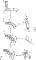
- Figure 1 shows a schematic exploded illustration of a coaxial plug 1 according to an embodiment according to the invention.
- the coaxial plug 1 has a desired geometry and comprises a cable section 2 and an interface section 4.
- the cable section 2 serves, according to the exemplary embodiment, to receive a strand 6 of a cable 8 in an electrically conductive manner.
- the strand 6 has, in this instance, already been crimped to an inner contact 10 of the cable section 2.
- the inner contact 10 may be pushed into an insulator 12 of the cable section 2.
- the insulator 12 consequently radially spaces the inner contact 10 apart from an outer contact 14 of the cable section 2.
- the tabs 16 of the outer contact 14 of the cable section 2 are not definitively bent over.
- the cable section 2 has a region 18 which is bent over through 90°.
- the bent-over region 18 has a rectangular cross-section for increasing a mechanical stability of the plug 1.
- a tubular receiving member 20 is configured for receiving the interface section 4 at the end.
- interface sections 4 with different lengths, whereby the plug 1 can be constructed in a modular manner.
- interface sections 4 which are shaped differently at the interface or which are configured for other product ranges, into the tubular receiving member 20.
- only a modular variant of the plug 1 is shown in the figures.
- the interface section 4 can be pushed into the receiving member 20 in a non-positive-locking manner, wherein an inner contact 22 of the interface section 4 can be connected in this instance in an electrically conductive manner to the inner contact 10 of the cable section 2.
- the inner contact 22 of the interface section 4 is clamped at the end between two metal tongues 23 of the inner contact 10 which are arranged at the end, so that an electrically conductive connection is produced.
- the inner contact 22 of the interface section 4 is spaced apart from an outer contact 26 of the interface section 4 by an insulator 24 of the interface section 4, and connected in a positionally fixed manner to the outer contact 26 indirectly via the insulator 24 to the outer contact 26.
- the outer contact 14 forms and, in the case of the interface section 4, the outer contact 26 forms the outer housing components.
- the interface section 4 is plugged together at the end in the receiving member 20 of the cable section 2, an electrically conductive connection is produced between the two outer contacts 14, 26.
- Figure 2 shows perspective illustrations of the coaxial plug 1 according to the embodiment.
- the interface section 4 is, in this instance, connected to the cable section 2 in a positive-locking and non-positive-locking manner.
- the inner contact 10 of the cable section 2 which is connected to the cable 8 in an electrically conductive manner, is inserted into the insulator 12, and the tabs 16 of the cable section 2 are bent over to mechanically fix the cable 8.
- the bent-over tabs 16 further act as a way of mechanically reducing the loading of the inner contact 10.
- the region 18, which is bent through 90°, is illustrated with a rectangular cross-section in order to increase the mechanical stability of the coaxial plug 1.
- FIG 3 shows a schematic sequence of a first portion of a method 30 for producing a coaxial plug 1 according to a first exemplary embodiment.
- the first portion of the method 30 involves, in particular, a production of the interface section 4 of the coaxial plug 1.
- the respective components 22, 24, 26 of the interface section 4 are in each case provided as an arrangement in a row of a large number of components 22, 24, 26, which are arranged on a belt or a roll, for producing the coaxial plug 1.
- the remaining portions 28 of the respective carrier belts or carrier bands are, for example, illustrated in the corresponding steps.
- the arrows indicate the method sequence for producing the interface section 4 as a first portion of the method 30.
- a plurality of inner contacts 22 with different geometry are provided.
- Each geometry of the inner contacts 22 correspond to one type of inner contacts 22.
- a first type of inner contacts 22 and a second type of inner contacts 22 can be provided.
- the second type of inner contacts 22 is longer than the first type of inner contacts 22.
- the first and the second type of inner contacts 22 can comprise a different cross-section geometry.
- a plurality of outer contacts 26 with a different geometry can be provided.
- Each geometry of the outer contacts 26 correspond to one type of outer contacts 26.
- a first type of outer contacts 26 and a second type of outer contact 26 can be provided.
- the second type of outer contacts 26 has bigger cross-section dimension than the first type of outer contacts 26.
- the geometry of the inner contacts 22 or the outer contacts 26 is predefined and only type of inner or outer contacts 22, 26 is provided.
- the other contacts 22, 26 at least two different embodiments/types of inner or outer contacts 22, 26 are provided.
- Each type of the inner contacts 22 and/or the outer contacts 26 can be provided with a (separate) carrier band.
- one (type) of the inner contacts 22 and/or one of the outer contacts 26 is/are selected.
- the selected inner contact 22 can be pushed into an inner opening of the insulator 24.
- the catch projections 32 of the inner contact 22 can engage in the recesses 34 of the insulator 24, and can fix the inner contact 22 in the insulator 24 in a positionally fixed manner.
- the insulator 24 can be pushed with the inserted selected inner contact 22 into a selected outer contact 26 of the interface section 4, which outer contact is bent in a tubular manner.
- catch tongues 36 in the outer contact 26 can engage and lock in a positive-locking manner in recesses 38 which are introduced in the insulator 24.
- This connection can also be produced in a concluding step by a subsequent local punching of the outer contact 26. Subsequently, the remaining portions 28 of the carrier band can be removed.
- Figure 4 illustrates a schematic sequence of a second portion of the method 30 for producing the coaxial plug 1 according to the first exemplary embodiment.
- the second portion of the method 30 particularly involves the production of the cable section 2 and the connection of the cable section 2 to the interface section 4 in order to form the coaxial plug 1.
- the second portion is similar to the first portion.
- the arrows indicate the sequence of the method 30.
- a pre-shaped outer contact 14 of the cable section 2 is provided.
- the pre-shaped outer contact 14 can be provided and further processed on a carrier band.
- a plurality of outer contacts 14 and/or inner contacts 10 with different geometry can be provided.
- Each geometry of the inner contacts 10 correspond to one type of inner contacts and each geometry of the outer contacts 14 correspond to one type of outer contacts 14.
- Each type of the inner contacts 10 and/or the outer contacts 14 can be provided with a (separate) carrier band.
- one of the outer contacts 14 and/or respectively one of the inner contacts 10 is/are selected.
- the remaining portions 28 of the carrier band are shown schematically.
- the insulator 12 of the cable section 2 is also provided as a portion of a large number of insulators 12 which are connected to each other on a roll.
- the remaining portions 28 of the carrier band are removed from the insulator 12.
- the insulator 12 is positioned in the (selected) outer contact 14.
- the insulator 12 is arranged in the outer contact 14 in a torsion-resistant manner.
- the (selected) inner contact 10 is connected to a strand 6 of the cable 8 mechanically and electrically.
- the inner contact 10 was crimped to the strand 6.
- the inner contact 10, which is connected to the cable 8, is subsequently arranged in the insulator 12 which is positioned in the outer contact 14.
- a subsequent bending-over of the pre-bent tabs 16 of the outer contact 14 allows a mechanical locking of the cable sheath 8 to the outer contact 14 of the cable section 2.
- the inner conductor 10 is retained at the end position thereof by the bent-over tabs 16 in a positionally fixed, torsion-resistant manner.
- a cable section 2 produced in such a manner can subsequently be connected to the interface section 4 in order to form the coaxial plug 1 with the desired geometry.
- the interface section 4 produced in the first portion of the method 30 is pushed into the receiving member 20 of the cable section 2.
- the outer contact 14 of the cable section 2 and the outer contact 26 of the interface section 4 can consequently be connected to each other in a frictionally engaging manner.
- the inner contact 22 projects in this case at the end into the metal tongues 23, which are arranged at the end, of the inner contact 10 of the cable section 2.
- the metal tongues 23 apply a resilient force to the rod-like inner contact 22, and consequently produce an electrically conductive connection between the inner contacts 10, 22.
- the outer contacts 14, 26 can be welded, soldered or subsequently compressed onto each other.
Landscapes
- Engineering & Computer Science (AREA)
- Manufacturing & Machinery (AREA)
- Coupling Device And Connection With Printed Circuit (AREA)
- Manufacturing Of Electrical Connectors (AREA)
Abstract
Description
- The invention relates to a method for producing at least one modularly configurable plug and a coaxial plug having an outer contact and an inner contact which is spaced apart from the outer contact by means of an insulator.
- This patent application claims the priority of the German
patent application DE 10 2018 101 764.2, filed January 26, 2018 with the title "Verfahren zum Herstellen eines modular aufbaubaren Koaxialsteckers" the disclosed content of which is hereby incorporated by reference in the entirety and for all purposes. - Plugs are conventionally used for producing a releasable electrically conductive plug connection with a socket or a coupling. Depending on the environmental conditions and requirements relating to electromagnetic compatibility, plugs with an outer contact can be used. The outer contact forms in this instance an electrically conductive outer sheath for shielding from electromagnetic fields.
- Depending on installation positions of the corresponding sockets, it may be necessary to use a plug which is angled through 90°. It is thereby possible, for example, to reduce a mechanical loading of the cables and the socket.
- The problem with such 90° sockets is, however, that they can be connected or crimped to cables manually or by means of semi-automatic devices developed specially for this purpose as so-called "loose-piece" components. Conventional devices or applicators for automatically joining the plug to a cable cannot receive and process the 90° plugs owing to the dimensions.
- The 90° plugs are often used as single-piece integrally constructed components for further connection to cables, so that changes to the plug can lead to exchange of the entire plug. Furthermore, such 90° plugs can only be packed in a laborious manner on coils or rolls and arranged for processing on a carrier strip.
-
- The object of the invention may be considered to be to propose a method for producing plugs in which the respective components of the plug can be selected in a variable manner and can be automatically processed with conventional applicators.
- This object is achieved by means of the respective subject-matter of the independent claims. Advantageous embodiments of the invention are the subject-matter of respective dependent subordinate claims.
- According to an aspect of the invention, a method for producing at least one modularly configurable plug is provided.
- At least one cable section is provided with at least one insulator which is arranged in at least one outer contact of the cable section of the at least one plug and at least one inner contact of a cable section which is arranged in the insulator. In order to form an interface section of the at least one plug a plurality of at least one inner contacts and/or outer contacts of the interface section with different length and/or shape are provided. One of the inner and/or outer contacts of the interface sections is selected to form the interface section. At least one insulator is arranged in at least one outer contact of the interface section and at least one inner contact of the interface section is arranged in the insulator. The at least one interface section is connected to the at least one cable section in order to form the plug.
- In one embodiment at least one insulator is inserted in at least one pre-shaped outer contact of a cable section of the at least one plug and at least one inner contact of a cable is positioned in the inserted insulator.
- Subsequently, the at least one pre-bent outer contact is shape-finished in order to form a cable section of the at least one plug.
- In order to form an interface section of the at least one plug, at least one insulator is inserted in at least one pre-shaped outer contact of the interface section and at least one inner contact of the interface section is positioned in the inserted insulator.
- In another step, the at least one interface section is connected to the at least one cable section in order to form the at least one plug.
- According to the invention, the cable section is adapted to a diameter of the cable and of the inner contact of the cable and the interface section is formed with a variable length or shape.
- As a result of the method, a plug can be constructed in several pieces, wherein the respective pieces can be produced one after the other or parallel with each other, including in an automated manner, using conventional applicators. The plug may consequently comprise a cable section which can be connected to a cable, for example by means of crimping or soldering, and comprise an interface section. The cable section may be produced separately from the interface section. The cable section and the interface section may form two pieces of a two-piece plug. These may in this instance be produced parallel with each other or one after the other. In another step, the cable section and the interface section may be connected to each other and consequently form the plug.
- As a result of the smaller dimensions of the individual pieces, the cable section and the interface section may be processed in automated processes using conventional applicators. The method for producing the modular plug can thereby be implemented in previous production steps without extensive modifications of the production devices. Preferably, the cable section may be able to be adapted to defined cable dimensions. The interface section may be able to be adapted in terms of its length and be able to be exchanged independently of the cable section. Consequently, a plug which can be used in a flexible and versatile manner can be produced, since a definitive selection of the interface section can be made, for example, only shortly before the process end. A plug which can be produced in such a modular manner can be adapted rapidly and in a flexible manner to different application fields. Differently shaped interface sections or interface sections of different lengths can also be combined with different cable sections, whereby the versatility of the plug can be further increased.
- In particular, a plug which is produced according to the method may be constructed in the form of retrofit kits. In this instance, a plurality of differently configured cable sections or cable sections which are suitable for different cable types and cable dimensions may be able to be combined with interface sections of different lengths or interface sections which are provided for different product ranges. During the production of the modular plug, consequently, interface sections with different lengths can be selected for assembly with a cable section in advance.
- According to an aspect of the method, the components of the at least one plug are provided in a manner positioned on at least one roll, at least one belt or at least one rod. The inner contacts of the respective cable sections, the inner contacts of the respective interface sections, the insulators of the cable sections and the interface sections and the outer contacts of the cable sections and the interface sections can be provided on rolls or so-called "reels". The components mentioned can thereby be supplied to one or more applicators on corresponding bands and processed one after the other. It is thereby possible to implement a high level of automation during the production of the plug and to establish a connection of the plug to a cable.
- According to another exemplary embodiment of the method, the at least one inner contact of the cable section of the at least one plug is connected to at least one electrically conductive strand of at least one cable and subsequently positioned in the at least one insulator of the cable section. The at least one strand of a cable may, in the context of the production of at least one cable section of the plug, be connected to the cable section in an electrically conductive manner. In particular, the cable or the at least one strand of the cable can be crimped or soldered to the inner contact before the inner contact is positioned in the insulator of the cable section. The electrically conductive connection to a cable can thereby already be carried out during production of the plug. Subsequent semi-automated connection of a plug, which has already been finished, to a cable is consequently not necessary.
- According to another exemplary embodiment of the method, as a result of the shape-finishing of the outer contact of the cable section of the at least one plug, a cable sheath is mechanically connected to the outer contact. As a result of this procedure, in a concluding step the cable section can be finished. In this instance, for example, tabs which have been pre-shaped in advance are definitively deformed in order to receive a cable after insertion of the inner contact which is connected to a cable in an insulator which is positioned in the outer contact. As a result of the bending, the tabs of the outer contact can be pressed against the cable sheath. A non-positive-locking mechanical connection between the outer contact of the cable section and the cable sheath can thereby be produced. This can be implemented in the context of automated production processes with one or more applicators.
- According to another exemplary embodiment of the method, the at least one insulator of the cable section of the at least one plug is inserted in a torsion-resistant manner into the at least one pre-shaped outer contact. Preferably, the insulator of the cable section may have recesses in which correspondingly arranged metal tongues, which are punched into the outer contact of the cable section, engage in a positive-locking manner. The insulator can thereby be pushed into the cable section as far as an end locking position. Consequently, errors during the production of the plug can be reduced, since unintentional torsion or release of the insulator is no longer possible. A torsion-resistant arrangement of the insulator may in particular be advantageous with a 90° plug, since the insulator of the cable section, for this purpose, must have end recesses in order to allow an end portion of the inner contact of the interface section to be received. It is thereby possible to produce an electrically conductive connection between the inner contact of the cable section and the inner contact of the interface section.
- According to another exemplary embodiment of the method, the at least one insulator of the interface section of the at least one plug is connected to the outer contact of the interface section in a manner fixed in position. Preferably, the outer contact of the interface section may have punched metal tongues which can engage in a groove which is arranged on the periphery of the insulator. In combination with an end shaping of the outer contact, the insulator of the interface section can be pushed into the end position thereof inside the outer contact and can be locked in the end position in a non-releasable, positive-locking manner by the metal tongues of the outer contact. It is thereby possible to connect the insulator to the outer contact in a technically simple manner by means of linear movement sequences. Assembly errors may in this instance be reduced, since unintentional release or displacement of the components is not possible after insertion of the insulator into the end position.
- According to another exemplary embodiment of the method, the at least one inner contact of the interface section of the at least one plug is positioned in a fixed manner in the insulator of the interface section. It is thereby possible to produce, together with a fixed positioning of the insulator in the outer contact of the interface section, an inner contact which is arranged in a fixed manner relative to the outer contact. Particularly by applying a pressure force to the outer contact when the interface section is plugged together with the cable section of the at least one plug, the inner contact of the interface section can be contacted in an electrically conductive manner with the inner contact of the cable section. Preferably, the interface section may be able to be inserted into an end recess of the cable section of the at least one plug. Consequently, the interface section may be able to be secured at the periphery to the outer contact of the cable section in a non-positive-locking or positive-locking manner. In addition, the cable section and the interface section can be welded or soldered. As a result of a peripheral connection between the interface section and the cable section, a resilient force may be produced between the inner contact of the cable section and the inner contact of the interface section, so that an electric current flow from the cable via the inner contact of the cable section to the inner contact of the interface section is possible. The resilient force may, for example, be produced by means of mutual bending-back of the inner contacts or by means of a positive-locking cooperation of the inner contacts at the end. A reliable electrical contacting can thereby be ensured.
- According to another exemplary embodiment of the method, during the connection of the at least one interface section to the at least one cable section in order to form the at least one plug, the at least one outer contact of the interface section is connected in an electrically conductive manner to the at least one outer contact of the cable section. Preferably, the outer contacts of the interface section and of the cable section during assembly can cooperate with each other in a positive-locking and/or non-positive-locking manner and consequently produce an electrically conductive connection. In addition, such a connection can be optimised by means of soldering or welding, so that ageing processes and corrosion processes can have less influence on the electrical connection.
- According to another exemplary embodiment of the method, during the connection of the at least one interface section to the at least one cable section in order to form the at least one plug, the at least one inner contact of the interface section is connected in an electrically conductive manner to the at least one inner contact of the cable section. It is thereby possible, in one step, to bring the outer contacts of the cable section and of the interface section and the inner contacts of the cable section and of the interface section into electrical contact with each other. A separate connection or soldering of the inner contacts can consequently be dispensed with. Advantageously, as a result of a positive-locking configuration at the end, the inner contacts may engage one in the other and cooperate. Alternatively, as a result of a resilient force which can be produced, the two inner contacts can be pressed against each other and consequently have the lowest possible electrical transition resistance.
- According to another aspect of the invention, a coaxial plug is provided. The coaxial plug is produced according to the above explained method. The plug has an outer contact and an inner contact which is spaced apart from the outer contact by means of an insulator, wherein the coaxial plug has a cable section, which can be adapted or is adapted to a cable for producing an electrical and mechanical connection with respect to at least one cable and an interface section, which is mechanically and electrically connected to the cable section and which can be selected so as to be variable in terms of length or shape, for producing a mechanical and electrical connection to a socket.
- The coaxial plug according to the invention is constructed in two pieces and can consequently be produced in several production steps from components with smaller dimensions. Since, in particular, the individual insulators, outer contacts and inner contacts can be constructed to be smaller than with a 90° plug which is constructed in one piece, they may be provided in a manner arranged in rows or connected on rolls or belts. The coaxial plug can thereby be processed by means of automated applicators and crimp devices.
- Since the coaxial plug comprises a separate cable section which is electrically and mechanically connected to a cable, the interface section can be produced and shaped independently of the cable section. It may, for example, be possible to vary a length, a diameter or an end shape of the interface section for differently constructed sockets. Furthermore, interface sections may be able to be combined in order to produce a mechanical and electrical connection of different product ranges to the cable section which can be adapted to a cable. Only a portion of a production method of the coaxial plug thereby has to be adapted. The cable section may, for example, remain the same so that, in the event of modifications and adaptations of the coaxial plug, a technical complexity can be reduced. In particular, as a result of such a modular construction, the coaxial plug may be able to be used in a versatile and flexible manner. The coaxial plugs may be able to be fitted in a combined state in order to produce an electrical and mechanical connection, for example, in a housing or a plug housing, so that, as a result of the modular design, the respective components of the coaxial plug can be used in a manner adapted to the different housing variants or housing shapes. The variants of the coaxial plugs may, for example, differ as a result of variable contact chamber lengths or lengths of the interface section or as a result of different shapes of the respective components of the interface section.
- Such a coaxial plug may, for example, be configured as a retrofit kit having interface sections which are available in different lengths and shapes and having cable sections which are adapted to different cable diameters and cable shapes.
- According to an exemplary embodiment of the coaxial plug, the interface section can be inserted at the end into a receiving member of the cable section. To this end, the cable section may be configured in a tubular manner at least at the end. The cable section may, for example, have resilient elements which are fitted at the end for applying a resilient force which is directed at the periphery into an inner space of the receiving member or into an inner space of the cable section at the end. An interface section which can be introduced into the receiving member or the end inner space of the cable section may preferably have an outer contour which is positive-locking with respect to the inner space at least in regions. The interface section can thereby be positioned in an optimum manner to form the coaxial plug in the receiving member of the cable section. As a result of the resilient force acting on the interface section, an electrical transition resistance between the cable section and the interface section can be reduced. In addition, the components may be soldered, welded or subsequently compressed with respect to each other.
- According to another exemplary embodiment of the coaxial plug, the coaxial plug is a 90° plug and the cable section is constructed in a manner bent through 90°. The cable section may thereby have particularly compact dimensions and be able to be supplied by means of conventional applicators and without specially produced machines and processed by said applicators. Preferably, the cable section has a receiving member at the end, which is bent through 90° with respect to a cable path for receiving the interface section. The interface section may in this instance preferably be configured in a linear manner.
- According to another exemplary embodiment of the coaxial plug, an inner contact of the cable section has, at the end, a receiving member for receiving an end portion of an inner contact of the interface section in a non-positive-locking, positive-locking or materially engaging manner. The inner contacts of the interface section and of the cable section can thereby be connected to each other in an electrically conductive manner by means of assembling or plugging together the interface section and the cable section. Preferably, the inner contacts may have resilient elements, catch tongues or the like at the end. It is thereby possible to produce a permanently acting force by means of which the two inner contacts are connected to each other at least in regions. Furthermore, it is consequently possible to produce an optimum electrical transition resistance. Alternatively, the two inner contacts can be soldered or welded to each other in an intermediate step or subsequently. To this end, the cable section may, for example, have an opening for introducing a laser welding nozzle. The two inner contacts may have, at the end, faces with applied tin solder which, by acting on the coaxial plug with heat, can be soldered to each other.
- According to another exemplary embodiment of the coaxial plug, the end portion of the inner contact of the interface section can be received at an angle of 90° by the end receiving member of the inner contact of the cable section. The coaxial plug is thereby constructed as a 90° plug. In particular, the cable section can form a leg and the interface section can form a second leg of the 90° plug. The cable section and the interface section can thereby be constructed in a particularly compact manner and consequently produced in a technically simple manner in the context of automated production processes and be electrically connected using cables.
- According to another exemplary embodiment of the coaxial plug, the cable section and the interface section of the coaxial plug can be mechanically and electrically connected to each other in a manner extending over product ranges. It is thereby possible not only to use the modular construction for a present-day product, but also to broaden plugs and interfaces of other product ranges. Different product ranges may in this instance have differently shaped interface sections and cable sections. The product ranges are, in this instance, in particular different plug connection types. In order to enable this adaptability, the geometric configuration of the connection between both contact halves of the coaxial plug, or between the cable section and the interface section, is always carried out in the same manner and/or so as to be able to cooperate mechanically and electrically with each other.
- Preferred exemplary embodiments of the invention are explained in greater detail below with reference to highly simplified schematic illustrations, in which:
- Fig. 1
- shows a schematic exploded illustration of a coaxial plug according to an embodiment,
- Fig. 2
- shows perspective illustrations of the coaxial plug according to an embodiment,
- Fig. 3
- shows a schematic sequence of a first portion of a method for producing a plug according to a first exemplary embodiment, and
- Fig. 4
- shows a schematic sequence of a second portion of the method for producing the plug according to the first embodiment.
- In the figures, the same structural elements have the same reference numerals in each case.
-
Figure 1 shows a schematic exploded illustration of acoaxial plug 1 according to an embodiment according to the invention. Thecoaxial plug 1 has a desired geometry and comprises acable section 2 and aninterface section 4. - The
cable section 2 serves, according to the exemplary embodiment, to receive astrand 6 of acable 8 in an electrically conductive manner. Thestrand 6 has, in this instance, already been crimped to aninner contact 10 of thecable section 2. Theinner contact 10 may be pushed into aninsulator 12 of thecable section 2. Theinsulator 12 consequently radially spaces theinner contact 10 apart from anouter contact 14 of thecable section 2. In the illustration, thetabs 16 of theouter contact 14 of thecable section 2 are not definitively bent over. - The
cable section 2 has aregion 18 which is bent over through 90°. The bent-overregion 18 has a rectangular cross-section for increasing a mechanical stability of theplug 1. On a side of thecable section 2 opposite thecable 8, atubular receiving member 20 is configured for receiving theinterface section 4 at the end. In this instance, it is possible, for example, to useinterface sections 4 with different lengths, whereby theplug 1 can be constructed in a modular manner. Furthermore, it may be possible to insertinterface sections 4, which are shaped differently at the interface or which are configured for other product ranges, into thetubular receiving member 20. For the sake of simplicity and by way of example, only a modular variant of theplug 1 is shown in the figures. - The
interface section 4 can be pushed into the receivingmember 20 in a non-positive-locking manner, wherein aninner contact 22 of theinterface section 4 can be connected in this instance in an electrically conductive manner to theinner contact 10 of thecable section 2. According to the exemplary embodiment, theinner contact 22 of theinterface section 4 is clamped at the end between twometal tongues 23 of theinner contact 10 which are arranged at the end, so that an electrically conductive connection is produced. - The
inner contact 22 of theinterface section 4 is spaced apart from anouter contact 26 of theinterface section 4 by aninsulator 24 of theinterface section 4, and connected in a positionally fixed manner to theouter contact 26 indirectly via theinsulator 24 to theouter contact 26. - In the case of the
cable section 2, theouter contact 14 forms and, in the case of theinterface section 4, theouter contact 26 forms the outer housing components. When theinterface section 4 is plugged together at the end in the receivingmember 20 of thecable section 2, an electrically conductive connection is produced between the twoouter contacts -
Figure 2 shows perspective illustrations of thecoaxial plug 1 according to the embodiment. In particular, in this instance the shape of thecoaxial plug 1 is illustrated. Theinterface section 4 is, in this instance, connected to thecable section 2 in a positive-locking and non-positive-locking manner. - Furthermore, the
inner contact 10 of thecable section 2, which is connected to thecable 8 in an electrically conductive manner, is inserted into theinsulator 12, and thetabs 16 of thecable section 2 are bent over to mechanically fix thecable 8. The bent-overtabs 16 further act as a way of mechanically reducing the loading of theinner contact 10. In this instance, in particular theregion 18, which is bent through 90°, is illustrated with a rectangular cross-section in order to increase the mechanical stability of thecoaxial plug 1. -
Figure 3 shows a schematic sequence of a first portion of amethod 30 for producing acoaxial plug 1 according to a first exemplary embodiment. The first portion of themethod 30 involves, in particular, a production of theinterface section 4 of thecoaxial plug 1. Therespective components interface section 4 are in each case provided as an arrangement in a row of a large number ofcomponents coaxial plug 1. The remainingportions 28 of the respective carrier belts or carrier bands are, for example, illustrated in the corresponding steps. The arrows indicate the method sequence for producing theinterface section 4 as a first portion of themethod 30. - In a first step, a plurality of
inner contacts 22 with different geometry are provided. Each geometry of theinner contacts 22 correspond to one type ofinner contacts 22. For example a first type ofinner contacts 22 and a second type ofinner contacts 22 can be provided. For example the second type ofinner contacts 22 is longer than the first type ofinner contacts 22. Also, the first and the second type ofinner contacts 22 can comprise a different cross-section geometry. - Additionally or alternatively, a plurality of
outer contacts 26 with a different geometry can be provided. Each geometry of theouter contacts 26 correspond to one type ofouter contacts 26. For example a first type ofouter contacts 26 and a second type ofouter contact 26 can be provided. For example the second type ofouter contacts 26 has bigger cross-section dimension than the first type ofouter contacts 26. - In a further embodiment, for example, the geometry of the
inner contacts 22 or theouter contacts 26 is predefined and only type of inner orouter contacts other contacts outer contacts - Each type of the
inner contacts 22 and/or theouter contacts 26 can be provided with a (separate) carrier band. - Depending on the desired geometry of the
plug 1 to be manufactured one (type) of theinner contacts 22 and/or one of theouter contacts 26 is/are selected. - After removal of the remaining
portions 28 of the carrier band, the selectedinner contact 22 can be pushed into an inner opening of theinsulator 24. In this case, thecatch projections 32 of theinner contact 22 can engage in therecesses 34 of theinsulator 24, and can fix theinner contact 22 in theinsulator 24 in a positionally fixed manner. - After removal of the remaining
portions 28 of the carrier band of theinsulator 24, theinsulator 24 can be pushed with the inserted selectedinner contact 22 into a selectedouter contact 26 of theinterface section 4, which outer contact is bent in a tubular manner. - Accordingly arranged
catch tongues 36 in theouter contact 26 can engage and lock in a positive-locking manner inrecesses 38 which are introduced in theinsulator 24. This connection can also be produced in a concluding step by a subsequent local punching of theouter contact 26. Subsequently, the remainingportions 28 of the carrier band can be removed. -
Figure 4 illustrates a schematic sequence of a second portion of themethod 30 for producing thecoaxial plug 1 according to the first exemplary embodiment. The second portion of themethod 30 particularly involves the production of thecable section 2 and the connection of thecable section 2 to theinterface section 4 in order to form thecoaxial plug 1. The second portion is similar to the first portion. The arrows indicate the sequence of themethod 30. - In one step, a pre-shaped
outer contact 14 of thecable section 2 is provided. As a result of the low structural height and width, the pre-shapedouter contact 14 can be provided and further processed on a carrier band. - In a further embodiment a plurality of
outer contacts 14 and/orinner contacts 10 with different geometry can be provided. Each geometry of theinner contacts 10 correspond to one type of inner contacts and each geometry of theouter contacts 14 correspond to one type ofouter contacts 14. Each type of theinner contacts 10 and/or theouter contacts 14 can be provided with a (separate) carrier band. - Depending on the desired geometry of the
plug 1 to be manufactured one of theouter contacts 14 and/or respectively one of theinner contacts 10 is/are selected.
The remainingportions 28 of the carrier band are shown schematically. Theinsulator 12 of thecable section 2 is also provided as a portion of a large number ofinsulators 12 which are connected to each other on a roll. The remainingportions 28 of the carrier band are removed from theinsulator 12. Subsequently, theinsulator 12 is positioned in the (selected)outer contact 14. As a result of the outer shape of theinsulator 12 corresponding to theouter contact 14, theinsulator 12 is arranged in theouter contact 14 in a torsion-resistant manner. - The (selected)
inner contact 10 is connected to astrand 6 of thecable 8 mechanically and electrically. According to the exemplary embodiment, theinner contact 10 was crimped to thestrand 6. Theinner contact 10, which is connected to thecable 8, is subsequently arranged in theinsulator 12 which is positioned in theouter contact 14. - A subsequent bending-over of the
pre-bent tabs 16 of theouter contact 14 allows a mechanical locking of thecable sheath 8 to theouter contact 14 of thecable section 2. In this case, theinner conductor 10 is retained at the end position thereof by the bent-overtabs 16 in a positionally fixed, torsion-resistant manner. Acable section 2 produced in such a manner can subsequently be connected to theinterface section 4 in order to form thecoaxial plug 1 with the desired geometry. - The
interface section 4 produced in the first portion of themethod 30 is pushed into the receivingmember 20 of thecable section 2. Theouter contact 14 of thecable section 2 and theouter contact 26 of theinterface section 4 can consequently be connected to each other in a frictionally engaging manner. - In a plugged-together state, the
inner contact 22 projects in this case at the end into themetal tongues 23, which are arranged at the end, of theinner contact 10 of thecable section 2. Themetal tongues 23 apply a resilient force to the rod-likeinner contact 22, and consequently produce an electrically conductive connection between theinner contacts outer contacts -
- 1
- Coaxial plug / plug
- 2
- Cable section
- 4
- Interface section
- 6
- Strand
- 8
- Cable / cable sheath
- 10
- Inner contact of the cable section
- 12
- Insulator of the cable section
- 14
- Outer contact of the cable section
- 16
- Metal tabs of the outer contact
- 18
- Bent-over region of the outer contact
- 20
- Tubular receiving member of the outer contact
- 22
- Inner contact of the interface section
- 23
- End metal tongues of the inner contact of the cable section
- 24
- Insulator of the interface section
- 26
- Outer contact of the interface section
- 28
- Remaining portions of a carrier band or carrier belt
- 30
- Method
- 32
- Catch projections of the
inner contact 22 - 34
- Recesses in the
insulator 24 - 36
- Catch tongues in the
outer contact 26 - 38
- Recesses in the
insulator 24
Claims (15)
- Method (30) for producing at least one modularly configurable plug (1), wherein- at least one cable section (2) is provided with at least one insulator (12) which is arranged in at least one outer contact (14) of the cable section (2) of the at least one plug (1) and at least one inner contact (10) of a cable section(8) which is arranged in the insulator (12),- in order to form an interface section (4) of the at least one plug (1) a plurality of at least one inner contacts (22) and/or outer contacts (26) of the interface section (4) with different length and/or shape are provided,- one of the inner and/or outer contacts (22, 26) of the interface sections (4) is selected to form the interface section (4),- at least one insulator (24) is arranged in at least one outer contact (26) of the interface section (4) and at least one inner contact (22) of the interface section (4) is arranged in the insulator (24),- the at least one interface section (4) is connected to the at least one cable section (2) in order to form the plug (1).
- Method according to Claim 1, wherein the components (10, 12, 14, 22, 24, 26) of the at least one plug (1) are provided in a manner positioned on at least one roll, at least one belt or at least one rod.
- Method according to Claim 1 or Claim 2, wherein the at least one inner contact (10) of the cable section (2) of the at least one plug (1) is connected to at least one electrically conductive strand (6) of at least one cable (8) and positioned in the at least one insulator (12) of the cable section (2).
- Method according to any one of Claims 1 to 3, wherein, as a result of the shape-finishing of the outer contact (14) of the cable section (2) of the at least one plug (1), a cable sheath (8) is mechanically connected to the outer contact (14) .
- Method according to any one of Claims 1 to 4, wherein the at least one insulator (12) of the cable section (2) of the at least one plug (1) is inserted in a torsion-resistant manner in the at least one pre-shaped outer contact (14).
- Method according to any one of Claims 1 to 5, wherein the at least one insulator (24) of the interface section (4) of the at least one plug (1) is connected to the outer contact (26) of the interface section (4) in a manner fixed in position.
- Method according to any one of Claims 1 to 6, wherein the at least one inner contact (22) of the interface section (4) of the at least one plug (1) is positioned in a fixed manner in the insulator (24) of the interface section (4).
- Method according to any one of Claims 1 to 7, wherein, during the connection of the at least one interface section (4) to the at least one cable section (2) in order to form the at least one plug (1), the at least one outer contact (26) of the interface section (4) is connected in an electrically conductive manner to the at least one outer contact (14) of the cable section (4).
- Method according to any one of Claims 1 to 8, wherein, during the connection of the at least one interface section (4) to the at least one cable section (2) in order to form the at least one plug (1), the at least one inner contact (22) of the interface section (4) is connected in an electrically conductive manner to the at least one inner contact (10) of the cable section (2).
- Coaxial plug (1) produced with the method (30) according to any one of Claims 1 to 9.
- Coaxial plug according to Claim 10, wherein the interface section (4) can be inserted at the end into a receiving member (20) of the cable section (2).
- Coaxial plug according to Claim 10 or Claim 11, wherein the coaxial plug (1) is a 90° plug (1) and the cable section (2) is constructed in a manner bent through 90°.
- Coaxial plug according to any one of Claims 10 to 12, wherein an inner contact (10) of the cable section (2) has, at the end, a receiving member (23) for receiving an end portion of an inner contact (22) of the interface section (4) in a non-positive-locking, positive-locking or materially engaging manner.
- Coaxial plug according to any one of Claims 10 to 13, wherein the end portion of the inner contact (22) of the interface section (4) can be received at an angle of 90° by the end receiving member (23) of the inner contact (10) of the cable section (2).
- Coaxial plug according to any one of Claims 10 to 14, wherein the cable section (2) and the interface section (4) of the coaxial plug (1) can be mechanically and electrically connected to each other in a manner extending over product ranges.
Applications Claiming Priority (1)
| Application Number | Priority Date | Filing Date | Title |
|---|---|---|---|
| DE102018101764.2A DE102018101764A1 (en) | 2018-01-26 | 2018-01-26 | Method for producing a modular coaxial plug |
Publications (1)
| Publication Number | Publication Date |
|---|---|
| EP3518353A1 true EP3518353A1 (en) | 2019-07-31 |
Family
ID=65241186
Family Applications (1)
| Application Number | Title | Priority Date | Filing Date |
|---|---|---|---|
| EP19154019.4A Pending EP3518353A1 (en) | 2018-01-26 | 2019-01-28 | Method for producing a modularly configurable coaxial plug |
Country Status (4)
| Country | Link |
|---|---|
| US (1) | US10938169B2 (en) |
| EP (1) | EP3518353A1 (en) |
| CN (1) | CN110086065B (en) |
| DE (1) | DE102018101764A1 (en) |
Cited By (1)
| Publication number | Priority date | Publication date | Assignee | Title |
|---|---|---|---|---|
| EP3783756A1 (en) * | 2019-08-20 | 2021-02-24 | Aptiv Technologies Limited | Connector for automotive applications and method of assembling thereof |
Families Citing this family (5)
| Publication number | Priority date | Publication date | Assignee | Title |
|---|---|---|---|---|
| DE102023106271A1 (en) | 2023-03-14 | 2024-09-19 | Md Elektronik Gmbh | Multi-piece coaxial connectors that can be variably configured in terms of interface geometry |
| DE102023106268A1 (en) | 2023-03-14 | 2024-09-19 | Md Elektronik Gmbh | INTERFACE GEOMETRY-CONFIGURABLE MULTI-PIECE COAXIAL CONNECTOR |
| DE102023106261A1 (en) | 2023-03-14 | 2024-09-19 | Md Elektronik Gmbh | INTERFACE GEOMETRY-CONFIGURABLE MULTI-PIECE COAXIAL CONNECTOR |
| DE102023116463B4 (en) | 2023-06-22 | 2025-03-13 | Fep Fahrzeugelektrik Pirna Gmbh & Co. Kg | Shielded HV connector with one-piece shielding sleeve |
| DE102024100909A1 (en) * | 2024-01-12 | 2025-07-17 | Bayerische Motoren Werke Aktiengesellschaft | Contact element component, method for producing a contact element component, contact element and contact element system |
Citations (5)
| Publication number | Priority date | Publication date | Assignee | Title |
|---|---|---|---|---|
| US6860761B2 (en) | 2003-01-13 | 2005-03-01 | Andrew Corporation | Right angle coaxial connector |
| DE102009043516A1 (en) * | 2009-09-30 | 2011-04-07 | Tyco Electronics Amp Gmbh | Two-piece contact element for high voltage connectors |
| US20120135625A1 (en) | 2010-11-25 | 2012-05-31 | Japan Aviation Electronics Industry, Limited | Connector and connector unit |
| WO2012116179A2 (en) | 2011-02-23 | 2012-08-30 | Molex Incorporated | Lockable mating connector |
| US20130203288A1 (en) * | 2012-02-03 | 2013-08-08 | Robert C. Hosler, Sr. | Coaxial angled adapter |
Family Cites Families (10)
| Publication number | Priority date | Publication date | Assignee | Title |
|---|---|---|---|---|
| US4209742A (en) * | 1976-10-13 | 1980-06-24 | Tektronix, Inc. | Modular probe system |
| FR2661286B1 (en) * | 1990-04-24 | 1992-08-14 | Tekelec Airtronic Sa | POWER DISTRIBUTOR DEVICE INCLUDING A SUPPORTING BODY OF A NUMBER OF COAXIAL CONNECTORS OF DIFFERENT DIMENSIONS. |
| US5122063A (en) * | 1991-02-06 | 1992-06-16 | Alliance Research Corporation | Adjustable electrical connector |
| US6406313B1 (en) * | 2001-01-04 | 2002-06-18 | Monster Cable Products, Inc. | Interchangeable connector system |
| US6916201B1 (en) * | 2004-03-03 | 2005-07-12 | Speed Tech Corp. | Micro coaxial cable connecting device |
| TWM285817U (en) * | 2005-05-18 | 2006-01-11 | Time Technology Ind Co Ltd F | Connector assembly having angular positioning structure |
| US7241169B1 (en) * | 2006-09-04 | 2007-07-10 | Hsien-Lin Yang | Adapter for power supply |
| WO2012023041A1 (en) * | 2010-08-19 | 2012-02-23 | Fci Automotive Holding | Electrical power terminal |
| US20130157505A1 (en) * | 2011-12-20 | 2013-06-20 | Tyco Electronics Corporation | Coaxial connector |
| CA3020163A1 (en) * | 2016-04-04 | 2017-10-12 | Ppc Broadband, Inc. | Angled coaxial connectors for receiving electrical conductor pins having different sizes |
-
2018
- 2018-01-26 DE DE102018101764.2A patent/DE102018101764A1/en active Pending
-
2019
- 2019-01-25 US US16/257,525 patent/US10938169B2/en active Active
- 2019-01-25 CN CN201910073888.4A patent/CN110086065B/en active Active
- 2019-01-28 EP EP19154019.4A patent/EP3518353A1/en active Pending
Patent Citations (5)
| Publication number | Priority date | Publication date | Assignee | Title |
|---|---|---|---|---|
| US6860761B2 (en) | 2003-01-13 | 2005-03-01 | Andrew Corporation | Right angle coaxial connector |
| DE102009043516A1 (en) * | 2009-09-30 | 2011-04-07 | Tyco Electronics Amp Gmbh | Two-piece contact element for high voltage connectors |
| US20120135625A1 (en) | 2010-11-25 | 2012-05-31 | Japan Aviation Electronics Industry, Limited | Connector and connector unit |
| WO2012116179A2 (en) | 2011-02-23 | 2012-08-30 | Molex Incorporated | Lockable mating connector |
| US20130203288A1 (en) * | 2012-02-03 | 2013-08-08 | Robert C. Hosler, Sr. | Coaxial angled adapter |
Cited By (3)
| Publication number | Priority date | Publication date | Assignee | Title |
|---|---|---|---|---|
| EP3783756A1 (en) * | 2019-08-20 | 2021-02-24 | Aptiv Technologies Limited | Connector for automotive applications and method of assembling thereof |
| US11637405B2 (en) | 2019-08-20 | 2023-04-25 | Aptiv Technologies Limited | Shielded electrical connector for automotive applications and method of assembling thereof |
| US12100915B2 (en) | 2019-08-20 | 2024-09-24 | Aptiv Technologies AG | Shielded electrical connector for automotive applications and method of assembling thereof |
Also Published As
| Publication number | Publication date |
|---|---|
| DE102018101764A1 (en) | 2019-08-01 |
| US20190237919A1 (en) | 2019-08-01 |
| CN110086065A (en) | 2019-08-02 |
| US10938169B2 (en) | 2021-03-02 |
| CN110086065B (en) | 2023-08-25 |
Similar Documents
| Publication | Publication Date | Title |
|---|---|---|
| CN110086065B (en) | Method of making a modularly configurable coaxial plug | |
| EP2019459B1 (en) | High performance coaxial connector | |
| EP2335326B1 (en) | Electrical contact, set of electrical contact, product and assembly comprising such an electrical contact, its method of manufacture and method of electrical connection | |
| JP5244427B2 (en) | Electronic component mounting / insulator-integrated inner conductor terminals and coaxial connectors | |
| EP2556565B1 (en) | Electromagnetic shielding device | |
| EP3159970B1 (en) | Cable assembly, connector, and method for manufacturing cable assembly | |
| US7601037B2 (en) | Terminal with multiple wire connection | |
| EP2149934B1 (en) | Coaxial connector inner contact arrangement | |
| CN112490735A (en) | Connectors and Assemblies for Automotive Applications | |
| US5307562A (en) | Method for making contact | |
| CN110770977B (en) | Plug-in connector part with press-fitted contact elements and method for producing the same | |
| EP1981123A2 (en) | A terminal fitting and crimping method therefor | |
| EP3783756A1 (en) | Connector for automotive applications and method of assembling thereof | |
| US20250030213A1 (en) | High Deformation and Retention Ferrule | |
| CN118402147A (en) | Two-part contact element for an electrical plug connection and method for producing such a contact element | |
| US4461530A (en) | Socket contact for electrical connectors and method of manufacture | |
| JP2008060035A (en) | connector | |
| EP0027393A1 (en) | Electrical contact assembly and method of making same | |
| US8272901B2 (en) | Crimp contacts and electrical connector assemblies including the same | |
| US20240313488A1 (en) | Multi-piece coaxial plug connector with variably configurable interface geometry | |
| US10862379B2 (en) | Stator assembling method for motor, stator structure for motor, and crimp terminal | |
| EP0027065B1 (en) | Method of manufacturing an electrical contact | |
| JP4495066B2 (en) | Joint connector | |
| JP6702665B2 (en) | L-type coaxial connector and manufacturing method thereof | |
| US20250202148A1 (en) | Angled End Of A Round Contact |
Legal Events
| Date | Code | Title | Description |
|---|---|---|---|
| PUAI | Public reference made under article 153(3) epc to a published international application that has entered the european phase |
Free format text: ORIGINAL CODE: 0009012 |
|
| STAA | Information on the status of an ep patent application or granted ep patent |
Free format text: STATUS: THE APPLICATION HAS BEEN PUBLISHED |
|
| AK | Designated contracting states |
Kind code of ref document: A1 Designated state(s): AL AT BE BG CH CY CZ DE DK EE ES FI FR GB GR HR HU IE IS IT LI LT LU LV MC MK MT NL NO PL PT RO RS SE SI SK SM TR |
|
| AX | Request for extension of the european patent |
Extension state: BA ME |
|
| STAA | Information on the status of an ep patent application or granted ep patent |
Free format text: STATUS: REQUEST FOR EXAMINATION WAS MADE |
|
| 17P | Request for examination filed |
Effective date: 20191230 |
|
| RBV | Designated contracting states (corrected) |
Designated state(s): AL AT BE BG CH CY CZ DE DK EE ES FI FR GB GR HR HU IE IS IT LI LT LU LV MC MK MT NL NO PL PT RO RS SE SI SK SM TR |
|
| R17P | Request for examination filed (corrected) |
Effective date: 20191230 |
|
| STAA | Information on the status of an ep patent application or granted ep patent |
Free format text: STATUS: EXAMINATION IS IN PROGRESS |
|
| 17Q | First examination report despatched |
Effective date: 20211020 |