EP3518309A1 - Pressurization mask and method for connecting top cap assembly and electrode tab by using pressurization mask - Google Patents
Pressurization mask and method for connecting top cap assembly and electrode tab by using pressurization mask Download PDFInfo
- Publication number
- EP3518309A1 EP3518309A1 EP18846535.5A EP18846535A EP3518309A1 EP 3518309 A1 EP3518309 A1 EP 3518309A1 EP 18846535 A EP18846535 A EP 18846535A EP 3518309 A1 EP3518309 A1 EP 3518309A1
- Authority
- EP
- European Patent Office
- Prior art keywords
- electrode tab
- mask
- current interrupt
- interrupt device
- pressurizing
- Prior art date
- Legal status (The legal status is an assumption and is not a legal conclusion. Google has not performed a legal analysis and makes no representation as to the accuracy of the status listed.)
- Granted
Links
Images



Classifications
-
- H—ELECTRICITY
- H01—ELECTRIC ELEMENTS
- H01M—PROCESSES OR MEANS, e.g. BATTERIES, FOR THE DIRECT CONVERSION OF CHEMICAL ENERGY INTO ELECTRICAL ENERGY
- H01M50/00—Constructional details or processes of manufacture of the non-active parts of electrochemical cells other than fuel cells, e.g. hybrid cells
- H01M50/10—Primary casings; Jackets or wrappings
- H01M50/172—Arrangements of electric connectors penetrating the casing
-
- B—PERFORMING OPERATIONS; TRANSPORTING
- B23—MACHINE TOOLS; METAL-WORKING NOT OTHERWISE PROVIDED FOR
- B23K—SOLDERING OR UNSOLDERING; WELDING; CLADDING OR PLATING BY SOLDERING OR WELDING; CUTTING BY APPLYING HEAT LOCALLY, e.g. FLAME CUTTING; WORKING BY LASER BEAM
- B23K26/00—Working by laser beam, e.g. welding, cutting or boring
- B23K26/20—Bonding
- B23K26/21—Bonding by welding
- B23K26/22—Spot welding
-
- H—ELECTRICITY
- H01—ELECTRIC ELEMENTS
- H01M—PROCESSES OR MEANS, e.g. BATTERIES, FOR THE DIRECT CONVERSION OF CHEMICAL ENERGY INTO ELECTRICAL ENERGY
- H01M10/00—Secondary cells; Manufacture thereof
- H01M10/04—Construction or manufacture in general
-
- H—ELECTRICITY
- H01—ELECTRIC ELEMENTS
- H01M—PROCESSES OR MEANS, e.g. BATTERIES, FOR THE DIRECT CONVERSION OF CHEMICAL ENERGY INTO ELECTRICAL ENERGY
- H01M10/00—Secondary cells; Manufacture thereof
- H01M10/04—Construction or manufacture in general
- H01M10/0422—Cells or battery with cylindrical casing
-
- H—ELECTRICITY
- H01—ELECTRIC ELEMENTS
- H01M—PROCESSES OR MEANS, e.g. BATTERIES, FOR THE DIRECT CONVERSION OF CHEMICAL ENERGY INTO ELECTRICAL ENERGY
- H01M50/00—Constructional details or processes of manufacture of the non-active parts of electrochemical cells other than fuel cells, e.g. hybrid cells
- H01M50/10—Primary casings; Jackets or wrappings
- H01M50/147—Lids or covers
-
- H—ELECTRICITY
- H01—ELECTRIC ELEMENTS
- H01M—PROCESSES OR MEANS, e.g. BATTERIES, FOR THE DIRECT CONVERSION OF CHEMICAL ENERGY INTO ELECTRICAL ENERGY
- H01M50/00—Constructional details or processes of manufacture of the non-active parts of electrochemical cells other than fuel cells, e.g. hybrid cells
- H01M50/10—Primary casings; Jackets or wrappings
- H01M50/172—Arrangements of electric connectors penetrating the casing
- H01M50/174—Arrangements of electric connectors penetrating the casing adapted for the shape of the cells
- H01M50/179—Arrangements of electric connectors penetrating the casing adapted for the shape of the cells for cells having curved cross-section, e.g. round or elliptic
-
- H—ELECTRICITY
- H01—ELECTRIC ELEMENTS
- H01M—PROCESSES OR MEANS, e.g. BATTERIES, FOR THE DIRECT CONVERSION OF CHEMICAL ENERGY INTO ELECTRICAL ENERGY
- H01M50/00—Constructional details or processes of manufacture of the non-active parts of electrochemical cells other than fuel cells, e.g. hybrid cells
- H01M50/50—Current conducting connections for cells or batteries
- H01M50/531—Electrode connections inside a battery casing
-
- H—ELECTRICITY
- H01—ELECTRIC ELEMENTS
- H01M—PROCESSES OR MEANS, e.g. BATTERIES, FOR THE DIRECT CONVERSION OF CHEMICAL ENERGY INTO ELECTRICAL ENERGY
- H01M50/00—Constructional details or processes of manufacture of the non-active parts of electrochemical cells other than fuel cells, e.g. hybrid cells
- H01M50/50—Current conducting connections for cells or batteries
- H01M50/572—Means for preventing undesired use or discharge
-
- H—ELECTRICITY
- H01—ELECTRIC ELEMENTS
- H01M—PROCESSES OR MEANS, e.g. BATTERIES, FOR THE DIRECT CONVERSION OF CHEMICAL ENERGY INTO ELECTRICAL ENERGY
- H01M50/00—Constructional details or processes of manufacture of the non-active parts of electrochemical cells other than fuel cells, e.g. hybrid cells
- H01M50/50—Current conducting connections for cells or batteries
- H01M50/572—Means for preventing undesired use or discharge
- H01M50/574—Devices or arrangements for the interruption of current
-
- H—ELECTRICITY
- H01—ELECTRIC ELEMENTS
- H01M—PROCESSES OR MEANS, e.g. BATTERIES, FOR THE DIRECT CONVERSION OF CHEMICAL ENERGY INTO ELECTRICAL ENERGY
- H01M50/00—Constructional details or processes of manufacture of the non-active parts of electrochemical cells other than fuel cells, e.g. hybrid cells
- H01M50/50—Current conducting connections for cells or batteries
- H01M50/572—Means for preventing undesired use or discharge
- H01M50/574—Devices or arrangements for the interruption of current
- H01M50/578—Devices or arrangements for the interruption of current in response to pressure
-
- B—PERFORMING OPERATIONS; TRANSPORTING
- B23—MACHINE TOOLS; METAL-WORKING NOT OTHERWISE PROVIDED FOR
- B23K—SOLDERING OR UNSOLDERING; WELDING; CLADDING OR PLATING BY SOLDERING OR WELDING; CUTTING BY APPLYING HEAT LOCALLY, e.g. FLAME CUTTING; WORKING BY LASER BEAM
- B23K2101/00—Articles made by soldering, welding or cutting
- B23K2101/36—Electric or electronic devices
-
- B—PERFORMING OPERATIONS; TRANSPORTING
- B23—MACHINE TOOLS; METAL-WORKING NOT OTHERWISE PROVIDED FOR
- B23K—SOLDERING OR UNSOLDERING; WELDING; CLADDING OR PLATING BY SOLDERING OR WELDING; CUTTING BY APPLYING HEAT LOCALLY, e.g. FLAME CUTTING; WORKING BY LASER BEAM
- B23K2101/00—Articles made by soldering, welding or cutting
- B23K2101/36—Electric or electronic devices
- B23K2101/38—Conductors
-
- H—ELECTRICITY
- H01—ELECTRIC ELEMENTS
- H01M—PROCESSES OR MEANS, e.g. BATTERIES, FOR THE DIRECT CONVERSION OF CHEMICAL ENERGY INTO ELECTRICAL ENERGY
- H01M2200/00—Safety devices for primary or secondary batteries
-
- H—ELECTRICITY
- H01—ELECTRIC ELEMENTS
- H01M—PROCESSES OR MEANS, e.g. BATTERIES, FOR THE DIRECT CONVERSION OF CHEMICAL ENERGY INTO ELECTRICAL ENERGY
- H01M2200/00—Safety devices for primary or secondary batteries
- H01M2200/20—Pressure-sensitive devices
-
- Y—GENERAL TAGGING OF NEW TECHNOLOGICAL DEVELOPMENTS; GENERAL TAGGING OF CROSS-SECTIONAL TECHNOLOGIES SPANNING OVER SEVERAL SECTIONS OF THE IPC; TECHNICAL SUBJECTS COVERED BY FORMER USPC CROSS-REFERENCE ART COLLECTIONS [XRACs] AND DIGESTS
- Y02—TECHNOLOGIES OR APPLICATIONS FOR MITIGATION OR ADAPTATION AGAINST CLIMATE CHANGE
- Y02E—REDUCTION OF GREENHOUSE GAS [GHG] EMISSIONS, RELATED TO ENERGY GENERATION, TRANSMISSION OR DISTRIBUTION
- Y02E60/00—Enabling technologies; Technologies with a potential or indirect contribution to GHG emissions mitigation
- Y02E60/10—Energy storage using batteries
-
- Y—GENERAL TAGGING OF NEW TECHNOLOGICAL DEVELOPMENTS; GENERAL TAGGING OF CROSS-SECTIONAL TECHNOLOGIES SPANNING OVER SEVERAL SECTIONS OF THE IPC; TECHNICAL SUBJECTS COVERED BY FORMER USPC CROSS-REFERENCE ART COLLECTIONS [XRACs] AND DIGESTS
- Y02—TECHNOLOGIES OR APPLICATIONS FOR MITIGATION OR ADAPTATION AGAINST CLIMATE CHANGE
- Y02P—CLIMATE CHANGE MITIGATION TECHNOLOGIES IN THE PRODUCTION OR PROCESSING OF GOODS
- Y02P70/00—Climate change mitigation technologies in the production process for final industrial or consumer products
- Y02P70/50—Manufacturing or production processes characterised by the final manufactured product
Definitions
- the present invention relates to a pressurizing mask, and a method for combining a top cap assembly and an electrode tab by using the pressurizing mask.
- rechargeable batteries are rechargeable and allow downsizing and large capacity as merits, so their development and use are recently increasing.
- a basic configuration of the rechargeable battery includes an electrode assembly including a positive electrode, a negative electrode, and a separation film, and an external material for sealing and receiving the electrode assembly with an electrolyte solution.
- the rechargeable battery for example, it may be referred to as a cylindrical rechargeable battery when the electrode assembly is spirally wound in a cylindrical form and is received in a metallic cylindrical can, and it may be referred to as a square rechargeable battery when its shape is square.
- a rectangular rechargeable battery in which an electrode assembly is received in a pouch-type case of a laminate sheet is referred to as a pouch-type rechargeable battery.
- the cylindrical rechargeable battery includes a cylindrical can and an electrode assembly received inside the cylindrical can as described above, and it further includes a top cap assembly combined to an upper portion of the cylindrical can.
- the top cap assembly is a member mounted on an opened upper end of the cylindrical can and sealed thereto, and it is also a member connected to the electrode tab of the electrode assembly and functioning as an electrode terminal.
- FIG. 1 shows a schematic structure of the top cap assembly
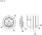
- FIG. 2 shows a schematic view of a process for combining a top cap assembly and an electrode tab.
- the top cap assembly 1 includes: a current interrupt device 30; a safety vent 20 connected to an upper portion of the current interrupt device 30, including a plurality of notches to be broken when a voltage is equal to or greater than an allowable voltage of the current interrupt device 30, and discharging gas provided inside the battery; a top cap 10 that is an electrode end electrically connected to the safety vent 20 and protruding upward; and a gasket 40 for wrapping and sealing an external circumferential surface of the current interrupt device 30, the safety vent 20, and the top cap 10.
- the top cap assembly 1 and an electrode assembly 50 may be physically and electrically coupled when bonded to the current interrupt device 30 and an electrode tab 55 of the electrode assembly 50 through welding.
- a method for pressurizing and fixing the electrode tab and the current interrupt device 30 by using a pressurizing mask 70 as shown in FIG. 2 for welding between the electrode tab 55 and the current interrupt device 30 is used.
- a center of the current interrupt device 30 is separated from the main body of the member 30 together with the safety vent 20 in an emergency, so it is usual for the electrode tab to be welded on a position away from the center of the current interrupt device 30.
- the mask 70 must be pressurized at the position away from the center of the current interrupt device 30, and resultantly, asymmetric pressure is applied to the top cap assembly 1, and the top cap assembly 1 may be asymmetrically transformed.
- top cap assembly 1 is formed by assembling a plurality of parts, the applying of asymmetric pressure may cause the parts to be dislocated or separated.
- the mask 70 pressurizes the electrode tab 55 provided on the current interrupt device 30 and the pressure is indirectly applied to the top cap assembly 1 through the current interrupt device 30, so it is difficult to firmly fix the current interrupt device 30 actually performing bonding, and the current interrupt device 30 may be partly transformed when a pressure is particularly provided to a portion closely attached to the electrode tab 55.
- An object of the present invention is to solve the problems of the prior art and technical problems from the past.
- the present invention has been made in an effort to provide a newly-structured pressurizing mask for applying a uniform pressure to an entire top cap assembly while pressurizing a current interrupt device and an electrode tab.
- the present invention has been made in another effort to provide a method for stably welding a current interrupt device and an electrode tab by using a pressurizing mask.
- An exemplary embodiment of the present invention provides a pressurizing mask for supporting a combination of a top cap assembly and an electrode assembly, including an external circumference forming a circle in a plane view, wherein a welding portion for exposing an electrode tab is formed at a biased position with respect to a center thereof, and an indent portion into which the electrode tab is inserted in formed in a peripheral portion of the welding portion.
- Merits of the present invention are that the indent portion is formed in the pressurizing mask, and in detail, a pressure is directly applied to the electrode tab inserted into the indent portion, a portion except the indent portion is attached to the current interrupt device, and a pressure may be directly applied to the current interrupt device.
- This may allow firm fixation and transformation prevention of the current interrupt device, in comparison with the structure in which a pressure is directly applied to the conventional mask, that is, the electrode tab and a pressure is indirectly applied to the current interrupt device through the electrode tab, thereby solving the problem according to prior art.
- a depth of the indent portion may be 99 % to 101 % of a thickness of the electrode tab, and a width of the indent portion may be 99 % to 101 % of a width of the electrode tab.
- a range of a depth and a width of the indent portion is determined in consideration of the fact that the tab is somewhat extended or compressed when the electrode tab is pressurized, and it may be designed to have a desired size according to a material of the electrode tab.
- the electrode tab protrudes higher than the indent portion, so it may be difficult to directly pressurize the current interrupt device, and when the depth exceeds a maximum of the range, the electrode tab may not be pressurized.
- the above description may also be applicable to the width of the indent portion.
- an indent portion may be formed on a first side to traverse the welding portion from the external circumference, and the electrode tab may be exposed to an outside through the welding portion on a second side that is an opposite side of the first side.
- the first side when an electrode tab is mounted to the indent portion, the first side may be configured to contact a current interrupt device of the top cap assembly, and when a pressure is applied in a direction of the first side from the second side, the current interrupt device and the electrode tab may be configured to be pressurized to support welding between the current interrupt device and the electrode tab.
- laser welding may be performed through the surface of the electrode tab exposed to the outside through the welding portion.
- the biased position may be at least one middle portion from among radii forming a space between a center and an external circumference, and the welding portion may be perforated at a position where a mass center on a plane corresponds to the middle portion.
- the welding portion is provided to be biased, so the electrode tab may be bonded to the center of the current interrupt device at a biased position.
- the welding portion may have an atypical form including a circle, an oval, a polygon, or at least one curved line in a plane view, and it is not limited to the above-noted examples.
- a material of the pressurizing mask may insulate electricity and may have predetermined elasticity, and for example, it may be a natural or synthetic rubber, or a polymer plastic such as polyethylene, polypropylene, or polyurethane, and the material of the pressurizing mask is not limited thereto.
- Another embodiment of the present invention provides a method for combining an electrode tab of an electrode assembly to a top cap assembly.
- the method includes: attaching an electrode tab to a current interrupt device of the top cap assembly; pressurizing the current blocking member with a pressurizing mask at which a welding portion for exposing at least part of the electrode tab is exposed; and bonding the electrode tab and the current interrupt device by welding the electrode tab exposed through the welding portion, wherein the mask is configured to pressurize while attached to 70 % to 90 % the area of the current interrupt device.
- an indent portion into which an electrode tab is inserted may be formed around the welding portion, and while the electrode tab is inserted into the indent portion, part thereof may be exposed through the welding portion, and the rest thereof may be pressurized in a direction of the current interrupt device by the indent portion of the mask.
- the electrode tab and the current interrupt device may be pressurized altogether and simultaneously by the pressurizing mask, and particularly, the mask is configured to pressurize while attached to 70 % to 90 % of the area of the current interrupt device, so the pressure may be dispersed and applied to a major part of the current interrupt device.
- the mask additionally pressurizes the current interrupt device via the electrode tab pressurized by the indent portion, so the entire mask including a welding portion is substantially pressurized and the dispersion of the above-noted pressure is more efficient.
- the current interrupt device and the mask may have an external circumference forming a circular shape in a plane view
- the mask may pressurize the current interrupt device at a position where centers of the current interrupt device and the mask correspond to each other, and the welding portion may be formed at a biased position with respect to a center of the mask.
- the pressures formed on the respective divided portions may be substantially the same and may be substantially uniformly dispersed in the directions going toward the external circumference from the center.
- an asymmetric transformation of the top cap assembly caused by applying an asymmetric pressure, and a mismatching or separation of parts of the top cap assembly may be solved.
- the welding may be laser welding.
- the indent portion into which the electrode tab may be inserted is formed, and when a pressure is applied, a pressure may be directly applied to the electrode tab, and the pressure may be directly applied to the portion except the indent portion while it is closely attached to the current interrupt device.
- the electrode tab and the current interrupt device may be pressurized together and simultaneously by the pressurizing mask, and particularly, the mask is configured to pressurize while the same is closely attached to 70 % to 90 % of the area of the current interrupt device, so the pressure may be dispersed and applied to most of the current interrupt device.
- the pressures generated by the respective divided portions may be formed to be substantially the same, the pressures may be substantially uniformly dispersed in all directions going to the external circumference from the center, and hence, according to the method according to the present invention, an asymmetric transformation of the top cap assembly caused by applying an asymmetric pressure, and a mismatching or separation of parts of the top cap assembly, may be solved.
- FIG. 3 shows schematic views (a, b) of respective sides of a pressurizing mask according to an exemplary embodiment of the present invention
- FIG. 4 shows a vertical cross-sectional view of a pressurizing mask with respect to a vertical line A-A'.
- the pressurizing mask 100 includes an external circumference forming a circle in a plane view.
- a welding portion 120 for exposing an electrode tab 140 is also formed at a position biased with respect to the center (c).
- the biased position signifies a middle portion of a radius (t) forming a space between the center (c) and the external circumference
- the welding portion 120 is perforated at a position where a mass center on a plane corresponds to the middle portion.
- an indent portion 110 into which the electrode tab 140 is inserted is formed on a peripheral portion of the welding portion 120.
- the indent portion 110 may be formed in a first side 101 to traverse the welding portion 120 from the external circumference, and the electrode tab 140 may be exposed to the outside through the welding portion 120 on a second side 102 that is an opposite side of the first side 101.
- the first side 101 may contact a current interrupt device (310 of FIG. 6 ) of a top cap assembly (300 of FIG. 6 ), and when a pressure is applied in the direction of the first side 101 from the second side 102, the current interrupt device (310 of FIG. 6 ) and the electrode tab 140 may be pressurized together to support the welding between the current interrupt device (310 of FIG. 6 ) and the electrode tab 140.
- the electrode tab 140 is exposed to the outside through the welding portion 120, and laser welding may be performed through the surface of the exposed electrode tab 140.
- the above-described pressurizing mask 100 includes the indent portion 110 into which the electrode tab 140 may be inserted, so it has a structural merit that, when a pressure is applied, the pressure may be directly applied to the electrode tab 140, and the pressure may be directly applied to the portion except the indent portion 110 while closely attached to the current interrupt device 310.
- FIG. 5 shows a flowchart of a method according to an exemplary embodiment of the present invention
- FIG. 6 shows a schematic view of a form for pressurizing a current interrupt device 310 of a top cap assembly 300 and an electrode tab 140 by using a pressurizing mask 100 according to an exemplary embodiment of the present invention.
- the electrode tab 140 is closely attached to the current interrupt device 310 of the top cap assembly 300 in step 210.
- the pressurizing mask 100 is closely attached to the current interrupt device 310 at a position where a center (not shown) of the current interrupt device 310 corresponds to a center (c) of the pressurizing mask 100, and in this instance, the electrode tab 140 is inserted into an indent portion 110 formed in one side of the pressurizing mask 100.
- the current interrupt device 310 is pressurized with the pressurizing mask 100, and in next step 230, laser welding is performed on the electrode tab 140 exposed through the welding portion 120 of the pressurizing mask 100.
- the mask 100 has an area of substantially 80 % of the area of the current interrupt device 310 and is closely attached to the current interrupt device 310 one-on-one, so most of the current interrupt device 310 may be pressurized, and the corresponding pressure may be dispersed to the current interrupt device 310.
- the current interrupt device 310 and the mask 100 have external circumferences forming to be circular in a plane view, so according to the present invention in which the mask 100 pressurizes the current interrupt device 310 at the position where the centers of the current interrupt device 310 and the mask 100 correspond to each other, when any kind of a virtual axis passing through the center (c) of the current interrupt device 310 and the pressurizing mask 100, for example, A-A' of FIG. 3 or B-B' of FIG. 6 is set to be a reference, the pressures formed on the respective divided portions are substantially the same, and the pressure may be substantially uniformly dispersed in all directions going toward the external circumference from the center (c).
- an asymmetric transformation of the top cap assembly 300 caused by applying an asymmetric pressure, and a mismatching or separation of parts of the top cap assembly 300 may be solved.
Landscapes
- Chemical & Material Sciences (AREA)
- Chemical Kinetics & Catalysis (AREA)
- Electrochemistry (AREA)
- General Chemical & Material Sciences (AREA)
- Engineering & Computer Science (AREA)
- Manufacturing & Machinery (AREA)
- Physics & Mathematics (AREA)
- Optics & Photonics (AREA)
- Plasma & Fusion (AREA)
- Mechanical Engineering (AREA)
- Connection Of Batteries Or Terminals (AREA)
Abstract
Description
- This application claims priority to and the benefit of Korean Patent Application No.
10-2017-0103196 - The present invention relates to a pressurizing mask, and a method for combining a top cap assembly and an electrode tab by using the pressurizing mask.
- In general, rechargeable batteries are rechargeable and allow downsizing and large capacity as merits, so their development and use are recently increasing.
- A basic configuration of the rechargeable battery includes an electrode assembly including a positive electrode, a negative electrode, and a separation film, and an external material for sealing and receiving the electrode assembly with an electrolyte solution.
- Regarding a characteristic of a form of the rechargeable battery, for example, it may be referred to as a cylindrical rechargeable battery when the electrode assembly is spirally wound in a cylindrical form and is received in a metallic cylindrical can, and it may be referred to as a square rechargeable battery when its shape is square. Exceptionally, a rectangular rechargeable battery in which an electrode assembly is received in a pouch-type case of a laminate sheet is referred to as a pouch-type rechargeable battery.
- Among them, the cylindrical rechargeable battery includes a cylindrical can and an electrode assembly received inside the cylindrical can as described above, and it further includes a top cap assembly combined to an upper portion of the cylindrical can.
- The top cap assembly is a member mounted on an opened upper end of the cylindrical can and sealed thereto, and it is also a member connected to the electrode tab of the electrode assembly and functioning as an electrode terminal.
- In relation to this,
FIG. 1 shows a schematic structure of the top cap assembly, andFIG. 2 shows a schematic view of a process for combining a top cap assembly and an electrode tab. - Referring to the drawings, the
top cap assembly 1 includes: acurrent interrupt device 30; asafety vent 20 connected to an upper portion of thecurrent interrupt device 30, including a plurality of notches to be broken when a voltage is equal to or greater than an allowable voltage of thecurrent interrupt device 30, and discharging gas provided inside the battery; atop cap 10 that is an electrode end electrically connected to thesafety vent 20 and protruding upward; and agasket 40 for wrapping and sealing an external circumferential surface of thecurrent interrupt device 30, thesafety vent 20, and thetop cap 10. - Regarding the above-noted structure, the
top cap assembly 1 and anelectrode assembly 50 may be physically and electrically coupled when bonded to thecurrent interrupt device 30 and anelectrode tab 55 of theelectrode assembly 50 through welding. - Further, a method for pressurizing and fixing the electrode tab and the
current interrupt device 30 by using a pressurizingmask 70 as shown inFIG. 2 for welding between theelectrode tab 55 and thecurrent interrupt device 30 is used. - However, a center of the
current interrupt device 30 is separated from the main body of themember 30 together with thesafety vent 20 in an emergency, so it is usual for the electrode tab to be welded on a position away from the center of thecurrent interrupt device 30. - Therefore, according to the above-described method, the
mask 70 must be pressurized at the position away from the center of thecurrent interrupt device 30, and resultantly, asymmetric pressure is applied to thetop cap assembly 1, and thetop cap assembly 1 may be asymmetrically transformed. - Further, since the
top cap assembly 1 is formed by assembling a plurality of parts, the applying of asymmetric pressure may cause the parts to be dislocated or separated. - In addition, the
mask 70 pressurizes theelectrode tab 55 provided on thecurrent interrupt device 30 and the pressure is indirectly applied to thetop cap assembly 1 through thecurrent interrupt device 30, so it is difficult to firmly fix thecurrent interrupt device 30 actually performing bonding, and thecurrent interrupt device 30 may be partly transformed when a pressure is particularly provided to a portion closely attached to theelectrode tab 55. - Accordingly, there is a great need for the development of a technology that can fundamentally solve the problem.
- An object of the present invention is to solve the problems of the prior art and technical problems from the past.
- In detail, the present invention has been made in an effort to provide a newly-structured pressurizing mask for applying a uniform pressure to an entire top cap assembly while pressurizing a current interrupt device and an electrode tab.
- The present invention has been made in another effort to provide a method for stably welding a current interrupt device and an electrode tab by using a pressurizing mask.
- An exemplary embodiment of the present invention provides a pressurizing mask for supporting a combination of a top cap assembly and an electrode assembly, including an external circumference forming a circle in a plane view, wherein a welding portion for exposing an electrode tab is formed at a biased position with respect to a center thereof, and an indent portion into which the electrode tab is inserted in formed in a peripheral portion of the welding portion.
- Merits of the present invention are that the indent portion is formed in the pressurizing mask, and in detail, a pressure is directly applied to the electrode tab inserted into the indent portion, a portion except the indent portion is attached to the current interrupt device, and a pressure may be directly applied to the current interrupt device.
- This may allow firm fixation and transformation prevention of the current interrupt device, in comparison with the structure in which a pressure is directly applied to the conventional mask, that is, the electrode tab and a pressure is indirectly applied to the current interrupt device through the electrode tab, thereby solving the problem according to prior art.
- In a detailed example, a depth of the indent portion may be 99 % to 101 % of a thickness of the electrode tab, and a width of the indent portion may be 99 % to 101 % of a width of the electrode tab.
- A range of a depth and a width of the indent portion is determined in consideration of the fact that the tab is somewhat extended or compressed when the electrode tab is pressurized, and it may be designed to have a desired size according to a material of the electrode tab.
- However, when the depth of the indent portion is less than a minimum of the above-noted range, the electrode tab protrudes higher than the indent portion, so it may be difficult to directly pressurize the current interrupt device, and when the depth exceeds a maximum of the range, the electrode tab may not be pressurized. The above description may also be applicable to the width of the indent portion.
- In a detailed example, an indent portion may be formed on a first side to traverse the welding portion from the external circumference, and the electrode tab may be exposed to an outside through the welding portion on a second side that is an opposite side of the first side.
- In the above-noted structure, regarding the pressurizing mask, when an electrode tab is mounted to the indent portion, the first side may be configured to contact a current interrupt device of the top cap assembly, and when a pressure is applied in a direction of the first side from the second side, the current interrupt device and the electrode tab may be configured to be pressurized to support welding between the current interrupt device and the electrode tab.
- Further, laser welding may be performed through the surface of the electrode tab exposed to the outside through the welding portion.
- The biased position may be at least one middle portion from among radii forming a space between a center and an external circumference, and the welding portion may be perforated at a position where a mass center on a plane corresponds to the middle portion.
- Therefore, when the electrode tab and the current interrupt device are pressurized at the position where the center of the pressurizing mask corresponds to the center of the current interrupt device, the welding portion is provided to be biased, so the electrode tab may be bonded to the center of the current interrupt device at a biased position.
- As described above, this is because the center of the current interrupt device is separated together with the safety vent in an emergency, the center is an inappropriate portion for the electrode tab to be welded, and the electrode tab is to be welded at the position that is biased from the center of the current interrupt device.
- The welding portion may have an atypical form including a circle, an oval, a polygon, or at least one curved line in a plane view, and it is not limited to the above-noted examples.
- A material of the pressurizing mask may insulate electricity and may have predetermined elasticity, and for example, it may be a natural or synthetic rubber, or a polymer plastic such as polyethylene, polypropylene, or polyurethane, and the material of the pressurizing mask is not limited thereto.
- Another embodiment of the present invention provides a method for combining an electrode tab of an electrode assembly to a top cap assembly.
- In detail, the method includes: attaching an electrode tab to a current interrupt device of the top cap assembly; pressurizing the current blocking member with a pressurizing mask at which a welding portion for exposing at least part of the electrode tab is exposed; and bonding the electrode tab and the current interrupt device by welding the electrode tab exposed through the welding portion, wherein the mask is configured to pressurize while attached to 70 % to 90 % the area of the current interrupt device.
- In the method according to the present invention, regarding the mask, an indent portion into which an electrode tab is inserted may be formed around the welding portion, and while the electrode tab is inserted into the indent portion, part thereof may be exposed through the welding portion, and the rest thereof may be pressurized in a direction of the current interrupt device by the indent portion of the mask.
- That is, according to the method according to the present invention, the electrode tab and the current interrupt device may be pressurized altogether and simultaneously by the pressurizing mask, and particularly, the mask is configured to pressurize while attached to 70 % to 90 % of the area of the current interrupt device, so the pressure may be dispersed and applied to a major part of the current interrupt device.
- Accordingly, partial transformation of the current interrupt device caused by the pressure may be prevented, and the pressure may be uniformly applied to the entire top cap assembly.
- Further, the mask additionally pressurizes the current interrupt device via the electrode tab pressurized by the indent portion, so the entire mask including a welding portion is substantially pressurized and the dispersion of the above-noted pressure is more efficient.
- In the present invention, the current interrupt device and the mask may have an external circumference forming a circular shape in a plane view, the mask may pressurize the current interrupt device at a position where centers of the current interrupt device and the mask correspond to each other, and the welding portion may be formed at a biased position with respect to a center of the mask.
- Therefore, when any kind of virtual axis passing through the current interrupt device and the center of the pressurizing mask is set as reference in a plane view, the pressures formed on the respective divided portions may be substantially the same and may be substantially uniformly dispersed in the directions going toward the external circumference from the center.
- Hence, according to the method according to the present invention, an asymmetric transformation of the top cap assembly caused by applying an asymmetric pressure, and a mismatching or separation of parts of the top cap assembly, may be solved.
- In another way, according to the present invention, the welding may be laser welding.
- As described above, regarding the pressurizing mask according to the present invention, the indent portion into which the electrode tab may be inserted is formed, and when a pressure is applied, a pressure may be directly applied to the electrode tab, and the pressure may be directly applied to the portion except the indent portion while it is closely attached to the current interrupt device.
- Regarding the method according to the present invention, the electrode tab and the current interrupt device may be pressurized together and simultaneously by the pressurizing mask, and particularly, the mask is configured to pressurize while the same is closely attached to 70 % to 90 % of the area of the current interrupt device, so the pressure may be dispersed and applied to most of the current interrupt device.
- Further, when any kind of virtual axis passing through the current interrupt device and the center of the pressurizing mask is set as a reference in a plane view, the pressures generated by the respective divided portions may be formed to be substantially the same, the pressures may be substantially uniformly dispersed in all directions going to the external circumference from the center, and hence, according to the method according to the present invention, an asymmetric transformation of the top cap assembly caused by applying an asymmetric pressure, and a mismatching or separation of parts of the top cap assembly, may be solved.
-
-
FIG. 1 shows a schematic view of a top cap assembly. -
FIG. 2 shows a schematic view of a coupling process for combining a top cap assembly and an electrode tab by using a mask according to prior art. -
FIG. 3 shows schematic views (a, b) of respective sides of a pressurizing mask according to an exemplary embodiment of the present invention. -
FIG. 4 shows a vertical cross-sectional view of a pressurizing mask with respect to a vertical line A-A' ofFIG. 3 . -
FIG. 5 shows a flowchart of a method according to an exemplary embodiment of the present invention. -
FIG. 6 shows a schematic view of formation of combining a top cap assembly and an electrode tab by using a mask according to an exemplary embodiment of the present invention. - Exemplary embodiments of the present invention will be described in detail with reference to the accompanying drawings. In describing the present invention, a description of known functions or configurations will be omitted so as to make the subject matter of the present invention more clear.
- To clearly describe the present invention, portions which do not relate to the description are omitted, and like reference numerals designate like elements throughout the specification. The size and thickness of each component shown in the drawings are arbitrarily shown for better understanding and ease of description, but the present invention is not limited thereto.
-
FIG. 3 shows schematic views (a, b) of respective sides of a pressurizing mask according to an exemplary embodiment of the present invention, andFIG. 4 shows a vertical cross-sectional view of a pressurizing mask with respect to a vertical line A-A'. - Referring to
FIG. 3 andFIG. 4 , the pressurizingmask 100 includes an external circumference forming a circle in a plane view. - Regarding the pressurizing
mask 100, awelding portion 120 for exposing anelectrode tab 140 is also formed at a position biased with respect to the center (c). - Here, the biased position signifies a middle portion of a radius (t) forming a space between the center (c) and the external circumference, and the
welding portion 120 is perforated at a position where a mass center on a plane corresponds to the middle portion. - Regarding the pressurizing
mask 100, in addition, anindent portion 110 into which theelectrode tab 140 is inserted is formed on a peripheral portion of thewelding portion 120. - The
indent portion 110 may be formed in afirst side 101 to traverse thewelding portion 120 from the external circumference, and theelectrode tab 140 may be exposed to the outside through thewelding portion 120 on asecond side 102 that is an opposite side of thefirst side 101. - Therefore, regarding the pressurizing
mask 100, while theelectrode tab 140 is mounted in theindent portion 110, thefirst side 101 may contact a current interrupt device (310 ofFIG. 6 ) of a top cap assembly (300 ofFIG. 6 ), and when a pressure is applied in the direction of thefirst side 101 from thesecond side 102, the current interrupt device (310 ofFIG. 6 ) and theelectrode tab 140 may be pressurized together to support the welding between the current interrupt device (310 ofFIG. 6 ) and theelectrode tab 140. - Further, the
electrode tab 140 is exposed to the outside through thewelding portion 120, and laser welding may be performed through the surface of the exposedelectrode tab 140. - The above-described
pressurizing mask 100 includes theindent portion 110 into which theelectrode tab 140 may be inserted, so it has a structural merit that, when a pressure is applied, the pressure may be directly applied to theelectrode tab 140, and the pressure may be directly applied to the portion except theindent portion 110 while closely attached to the current interruptdevice 310. -
FIG. 5 shows a flowchart of a method according to an exemplary embodiment of the present invention, andFIG. 6 shows a schematic view of a form for pressurizing a current interruptdevice 310 of atop cap assembly 300 and anelectrode tab 140 by using a pressurizingmask 100 according to an exemplary embodiment of the present invention. - To help understand the invention, a configuration of the pressurizing
mask 100 described with reference toFIG. 3 andFIG. 4 will be described in combination with a description to be provided hereinafter. - Referring to
FIG. 3 to FIG. 6 , theelectrode tab 140 is closely attached to the current interruptdevice 310 of thetop cap assembly 300 instep 210. After this, instep 220, the pressurizingmask 100 is closely attached to the current interruptdevice 310 at a position where a center (not shown) of the current interruptdevice 310 corresponds to a center (c) of the pressurizingmask 100, and in this instance, theelectrode tab 140 is inserted into anindent portion 110 formed in one side of the pressurizingmask 100. - In the present step, while the
electrode tab 140 is completely inserted into theindent portion 110, the current interruptdevice 310 is pressurized with the pressurizingmask 100, and innext step 230, laser welding is performed on theelectrode tab 140 exposed through thewelding portion 120 of the pressurizingmask 100. - As shown in
FIG. 6 , themask 100 has an area of substantially 80 % of the area of the current interruptdevice 310 and is closely attached to the current interruptdevice 310 one-on-one, so most of the current interruptdevice 310 may be pressurized, and the corresponding pressure may be dispersed to the current interruptdevice 310. - Further, the current interrupt
device 310 and themask 100 have external circumferences forming to be circular in a plane view, so according to the present invention in which themask 100 pressurizes the current interruptdevice 310 at the position where the centers of the current interruptdevice 310 and themask 100 correspond to each other, when any kind of a virtual axis passing through the center (c) of the current interruptdevice 310 and the pressurizingmask 100, for example, A-A' ofFIG. 3 or B-B' ofFIG. 6 is set to be a reference, the pressures formed on the respective divided portions are substantially the same, and the pressure may be substantially uniformly dispersed in all directions going toward the external circumference from the center (c). - Hence, according to the method according to the present invention, an asymmetric transformation of the
top cap assembly 300 caused by applying an asymmetric pressure, and a mismatching or separation of parts of thetop cap assembly 300 may be solved. - Specific exemplary embodiments of the present invention have been described and illustrated above, but the present invention is not limited to the above-mentioned exemplary embodiments. Therefore, the present invention can be variously changed and modified from the description by a person skilled in the art to which the present invention pertains without departing from the idea and scope of the present invention. Therefore, modified examples or changed examples are not to be individually construed from the technical spirit or aspect of the present invention, and therefore, the modified exemplary embodiments are to be construed to be included in the claims of the present invention.
Claims (13)
- A pressurizing mask for supporting a combination of a top cap assembly and an electrode assembly, comprising:
an external circumference forming a circle on a plane view, wherein a welding portion for exposing an electrode tab is formed at a biased position with respect to a center thereof, and an indent portion into which the electrode tab is inserted in formed in a peripheral portion of the welding portion. - The pressurizing mask of claim 1, wherein
a depth of the indent portion is 99 % to 101 % of a thickness of the electrode tab, and
a width of the indent portion is 99 % to 101 % of a width of the electrode tab. - The pressurizing mask of claim 1, wherein
an indent portion is formed on a first side to traverse the welding portion from the external circumference, and
the electrode tab is exposed to an outside through the welding portion on a second side that is an opposite side of the first side. - The pressurizing mask of claim 3, wherein
when an electrode tab is mounted to the indent portion, the first side is configured to contact a current interrupt device of the top cap assembly, and
when a pressure is applied in a direction of the first side from the second side, the current interrupt device and the electrode tab are configured to be pressurized to support welding between the current interrupt device and the electrode tab. - The pressurizing mask of claim 1, wherein
the biased position is at least one middle portion from among radii forming a space between a center and an external circumference, and
the welding portion is perforated at a position where a mass center on a plane corresponds to the middle portion. - The pressurizing mask of claim 1, wherein
the welding portion has an atypical form including a circle, an oval, a polygon, or at least one curved line in a plane view. - A method for combining an electrode tab of an electrode assembly to a top cap assembly, comprising:attaching an electrode tab to a current interrupt device of the top cap assembly;pressurizing the current blocking member with a pressurizing mask at which a welding portion for exposing at least part of the electrode tab is exposed;andbonding the electrode tab and the current interrupt device by welding the electrode tab exposed through the welding portion,wherein the mask is configured to pressurize while attached to 70 % to 90 % of the area of the current interrupt device.
- The method of claim 7, wherein
regarding the mask, an indent portion into which an electrode tab is inserted is formed around the welding portion. - The method of claim 8, wherein
while the electrode tab is inserted into the indent portion, a part thereof is exposed through the welding portion, and the rest thereof is pressurized in a direction of the current interrupt device by the indent portion of the mask. - The method of claim 9, wherein
the mask additionally pressurizes the current interrupt device through the electrode tab pressurized by an indent portion. - The method of claim 9, wherein
the current interrupt device and the mask have an external circumference forming a circular shape in a plane view. - The method of claim 11, wherein
the mask pressurizes the current interrupt device at a position where centers of the current interrupt device and the mask correspond to each other. - The method of claim 12, wherein
the welding portion is formed at a biased position with respect to a center of the mask.
Applications Claiming Priority (2)
| Application Number | Priority Date | Filing Date | Title |
|---|---|---|---|
| KR1020170103196A KR102345403B1 (en) | 2017-08-14 | 2017-08-14 | Pressurizing Mask and Method for Joining Top Cap Assembly and Electrode Tab By Using Pressurizing Mask |
| PCT/KR2018/009279 WO2019035620A1 (en) | 2017-08-14 | 2018-08-13 | Pressurization mask and method for connecting top cap assembly and electrode tab by using pressurization mask |
Publications (3)
| Publication Number | Publication Date |
|---|---|
| EP3518309A1 true EP3518309A1 (en) | 2019-07-31 |
| EP3518309A4 EP3518309A4 (en) | 2020-01-15 |
| EP3518309B1 EP3518309B1 (en) | 2023-07-26 |
Family
ID=65362248
Family Applications (1)
| Application Number | Title | Priority Date | Filing Date |
|---|---|---|---|
| EP18846535.5A Active EP3518309B1 (en) | 2017-08-14 | 2018-08-13 | Pressurizing mask and method for joining top cap assembly and electrode tab by using pressurizing mask |
Country Status (5)
| Country | Link |
|---|---|
| US (1) | US11623303B2 (en) |
| EP (1) | EP3518309B1 (en) |
| KR (1) | KR102345403B1 (en) |
| CN (1) | CN109906520B (en) |
| WO (1) | WO2019035620A1 (en) |
Family Cites Families (27)
| Publication number | Priority date | Publication date | Assignee | Title |
|---|---|---|---|---|
| JP3387118B2 (en) | 1992-06-12 | 2003-03-17 | ソニー株式会社 | Sealed battery |
| JP2595201Y2 (en) * | 1993-04-09 | 1999-05-24 | 富士電気化学株式会社 | Spiral battery |
| KR100560487B1 (en) * | 1998-12-28 | 2006-05-26 | 삼성에스디아이 주식회사 | Lithium secondary battery |
| JP2001148240A (en) | 1999-11-22 | 2001-05-29 | Nec Corp | Secondary battery and method of manufacturing the same |
| US7659029B2 (en) * | 2004-10-26 | 2010-02-09 | Nissan Motor Co., Ltd. | Battery module with insulating plates nipping electrode tabs |
| JP4997819B2 (en) * | 2006-04-28 | 2012-08-08 | トヨタ自動車株式会社 | Battery module |
| CN2936531Y (en) * | 2006-08-11 | 2007-08-22 | 深圳市比克电池有限公司 | Ultrasonic welding device for welding lithium-ion battery tab and cover assembly |
| CN101192656B (en) * | 2006-11-25 | 2010-07-21 | 深圳市比克电池有限公司 | Manufacturing method of battery |
| KR100882916B1 (en) | 2007-08-27 | 2009-02-10 | 삼성에스디아이 주식회사 | Secondary battery |
| KR100947989B1 (en) | 2007-11-06 | 2010-03-18 | 삼성에스디아이 주식회사 | Secondary Battery and Manufacturing Method Thereof |
| JP2009266714A (en) | 2008-04-28 | 2009-11-12 | Komatsulite Mfg Co Ltd | Safety device |
| KR100966549B1 (en) * | 2008-10-14 | 2010-06-29 | 주식회사 엘지화학 | Cap assembly with improved safety and cylindrical secondary battery containing same |
| US9017860B2 (en) | 2009-02-26 | 2015-04-28 | Samsung Sdi Co., Ltd. | Cylinder type secondary battery |
| CN201838638U (en) * | 2010-05-20 | 2011-05-18 | 深圳市比克电池有限公司 | Battery cap combination and cylindrical secondary battery |
| US8614017B2 (en) * | 2010-10-27 | 2013-12-24 | Medtronic, Inc. | Electrochemical cell with electrode elements that include alignment aperatures |
| WO2013009148A2 (en) * | 2011-07-13 | 2013-01-17 | 주식회사 엘지화학 | Cylindrical rechargeable battery |
| CN103688389B (en) * | 2011-07-20 | 2016-09-28 | 株式会社杰士汤浅国际 | Cylindrical battery |
| KR101446161B1 (en) * | 2011-08-17 | 2014-10-01 | 주식회사 엘지화학 | Cap assembly and secondary battery using the same |
| KR20130034284A (en) * | 2011-09-28 | 2013-04-05 | (주)아이비티 | Current interrupting device and secondary battery using the same |
| KR20130040576A (en) | 2011-10-14 | 2013-04-24 | 삼성에스디아이 주식회사 | Rechargeable battery |
| JP6208687B2 (en) * | 2012-12-19 | 2017-10-04 | 三洋電機株式会社 | Cylindrical secondary battery and manufacturing method thereof |
| KR101826879B1 (en) * | 2013-11-04 | 2018-02-07 | 주식회사 엘지화학 | Current interrupting device and Secondary battery using the same |
| EP2993716B1 (en) * | 2014-08-14 | 2017-12-13 | Samsung SDI Co., Ltd. | Battery having cap plate coupled to electrode lead |
| KR102381777B1 (en) * | 2015-02-25 | 2022-04-01 | 삼성에스디아이 주식회사 | Battery pack |
| CN205177894U (en) * | 2015-11-25 | 2016-04-20 | 深圳市沃特玛电池有限公司 | Super die block that welds of lithium ion battery block |
| KR102668193B1 (en) * | 2016-01-04 | 2024-05-23 | 삼성에스디아이 주식회사 | Cap assembly and secondary battery including the same |
| WO2018030679A1 (en) * | 2016-08-11 | 2018-02-15 | Shin Heung Energy & Electronic Co.,Ltd. | Cap assembly for preventing electrical shorting and secondary battery including the same |
-
2017
- 2017-08-14 KR KR1020170103196A patent/KR102345403B1/en active Active
-
2018
- 2018-08-13 CN CN201880004157.8A patent/CN109906520B/en active Active
- 2018-08-13 US US16/340,987 patent/US11623303B2/en active Active
- 2018-08-13 WO PCT/KR2018/009279 patent/WO2019035620A1/en not_active Ceased
- 2018-08-13 EP EP18846535.5A patent/EP3518309B1/en active Active
Also Published As
| Publication number | Publication date |
|---|---|
| KR20190018338A (en) | 2019-02-22 |
| US11623303B2 (en) | 2023-04-11 |
| EP3518309B1 (en) | 2023-07-26 |
| US20190291207A1 (en) | 2019-09-26 |
| WO2019035620A1 (en) | 2019-02-21 |
| CN109906520B (en) | 2021-05-28 |
| CN109906520A (en) | 2019-06-18 |
| EP3518309A4 (en) | 2020-01-15 |
| KR102345403B1 (en) | 2021-12-29 |
Similar Documents
| Publication | Publication Date | Title |
|---|---|---|
| US10615381B2 (en) | Cap assembly for secondary battery | |
| US11876245B2 (en) | Sealed battery comprising an elastic deformation part that is folded | |
| EP3614451B1 (en) | Secondary battery | |
| US9793572B2 (en) | Rechargeable battery | |
| KR101100990B1 (en) | Secondary battery | |
| KR20090099241A (en) | Cap assembly and secondary battery having the same | |
| US9692038B2 (en) | Cap for electrochemical cell | |
| CN105960718B (en) | Battery case and battery | |
| KR20190093360A (en) | Cap Assembly Having Rivet, and Cylindrical Battery Comprising Beading-part free and Climping-part free and the Cap Assembly | |
| US10256444B2 (en) | Electricity storage device | |
| KR20190042801A (en) | Sealing Block to Prevent Crack of Pouch-Type Secondary Battery, Pouch-Type Battery Case and Sealing Method for Pouch-Type Battery Case Using thereof | |
| CN106104857A (en) | Secondary cell | |
| KR101034719B1 (en) | Secondary battery | |
| US20120315513A1 (en) | Lithium secondary battery | |
| EP3518309B1 (en) | Pressurizing mask and method for joining top cap assembly and electrode tab by using pressurizing mask | |
| KR101446161B1 (en) | Cap assembly and secondary battery using the same | |
| US11640880B2 (en) | Energy storage device | |
| US12288886B2 (en) | Battery | |
| KR20190011515A (en) | Secondary battery | |
| KR101850181B1 (en) | Cylindrical lithium ion secondary battery | |
| JP2022552858A (en) | Cylindrical rechargeable battery with flexible input | |
| KR102248230B1 (en) | Secondary battery module | |
| CN109560219A (en) | Storage assembly | |
| JP2015185371A (en) | Power storage device | |
| KR20150033276A (en) | The secondary battery with increased bonding strength between electrode assembly and the battery case |
Legal Events
| Date | Code | Title | Description |
|---|---|---|---|
| STAA | Information on the status of an ep patent application or granted ep patent |
Free format text: STATUS: THE INTERNATIONAL PUBLICATION HAS BEEN MADE |
|
| PUAI | Public reference made under article 153(3) epc to a published international application that has entered the european phase |
Free format text: ORIGINAL CODE: 0009012 |
|
| STAA | Information on the status of an ep patent application or granted ep patent |
Free format text: STATUS: REQUEST FOR EXAMINATION WAS MADE |
|
| 17P | Request for examination filed |
Effective date: 20190426 |
|
| AK | Designated contracting states |
Kind code of ref document: A1 Designated state(s): AL AT BE BG CH CY CZ DE DK EE ES FI FR GB GR HR HU IE IS IT LI LT LU LV MC MK MT NL NO PL PT RO RS SE SI SK SM TR |
|
| AX | Request for extension of the european patent |
Extension state: BA ME |
|
| A4 | Supplementary search report drawn up and despatched |
Effective date: 20191217 |
|
| RIC1 | Information provided on ipc code assigned before grant |
Ipc: B23K 101/38 20060101ALI20191211BHEP Ipc: H01M 2/34 20060101ALI20191211BHEP Ipc: H01M 10/04 20060101ALN20191211BHEP Ipc: H01M 2/02 20060101ALI20191211BHEP Ipc: H01M 2/26 20060101ALI20191211BHEP Ipc: H01M 2/06 20060101AFI20191211BHEP |
|
| DAV | Request for validation of the european patent (deleted) | ||
| DAX | Request for extension of the european patent (deleted) | ||
| RAP1 | Party data changed (applicant data changed or rights of an application transferred) |
Owner name: LG ENERGY SOLUTION LTD. |
|
| RAP3 | Party data changed (applicant data changed or rights of an application transferred) |
Owner name: LG ENERGY SOLUTION, LTD. |
|
| REG | Reference to a national code |
Ref country code: DE Ref legal event code: R079 Free format text: PREVIOUS MAIN CLASS: H01M0002060000 Ipc: B23K0101380000 Ref document number: 602018054226 Country of ref document: DE |
|
| RIC1 | Information provided on ipc code assigned before grant |
Ipc: H01M 10/04 20060101ALN20230215BHEP Ipc: H01M 50/574 20210101ALI20230215BHEP Ipc: H01M 50/531 20210101ALI20230215BHEP Ipc: H01M 50/179 20210101ALI20230215BHEP Ipc: H01M 50/147 20210101ALI20230215BHEP Ipc: B23K 101/38 20060101AFI20230215BHEP |
|
| RIC1 | Information provided on ipc code assigned before grant |
Ipc: H01M 10/04 20060101ALN20230307BHEP Ipc: H01M 50/574 20210101ALI20230307BHEP Ipc: H01M 50/531 20210101ALI20230307BHEP Ipc: H01M 50/179 20210101ALI20230307BHEP Ipc: H01M 50/147 20210101ALI20230307BHEP Ipc: B23K 101/38 20060101AFI20230307BHEP |
|
| RIC1 | Information provided on ipc code assigned before grant |
Ipc: H01M 10/04 20060101ALN20230327BHEP Ipc: H01M 50/574 20210101ALI20230327BHEP Ipc: H01M 50/531 20210101ALI20230327BHEP Ipc: H01M 50/179 20210101ALI20230327BHEP Ipc: H01M 50/147 20210101ALI20230327BHEP Ipc: B23K 101/38 20060101AFI20230327BHEP |
|
| GRAP | Despatch of communication of intention to grant a patent |
Free format text: ORIGINAL CODE: EPIDOSNIGR1 |
|
| STAA | Information on the status of an ep patent application or granted ep patent |
Free format text: STATUS: GRANT OF PATENT IS INTENDED |
|
| RIC1 | Information provided on ipc code assigned before grant |
Ipc: H01M 10/04 20060101ALN20230411BHEP Ipc: H01M 50/574 20210101ALI20230411BHEP Ipc: H01M 50/531 20210101ALI20230411BHEP Ipc: H01M 50/179 20210101ALI20230411BHEP Ipc: H01M 50/147 20210101ALI20230411BHEP Ipc: B23K 101/38 20060101AFI20230411BHEP |
|
| INTG | Intention to grant announced |
Effective date: 20230512 |
|
| GRAS | Grant fee paid |
Free format text: ORIGINAL CODE: EPIDOSNIGR3 |
|
| P01 | Opt-out of the competence of the unified patent court (upc) registered |
Effective date: 20230516 |
|
| GRAA | (expected) grant |
Free format text: ORIGINAL CODE: 0009210 |
|
| STAA | Information on the status of an ep patent application or granted ep patent |
Free format text: STATUS: THE PATENT HAS BEEN GRANTED |
|
| AK | Designated contracting states |
Kind code of ref document: B1 Designated state(s): AL AT BE BG CH CY CZ DE DK EE ES FI FR GB GR HR HU IE IS IT LI LT LU LV MC MK MT NL NO PL PT RO RS SE SI SK SM TR |
|
| REG | Reference to a national code |
Ref country code: CH Ref legal event code: EP |
|
| REG | Reference to a national code |
Ref country code: IE Ref legal event code: FG4D |
|
| REG | Reference to a national code |
Ref country code: DE Ref legal event code: R096 Ref document number: 602018054226 Country of ref document: DE |
|
| REG | Reference to a national code |
Ref country code: LT Ref legal event code: MG9D |
|
| REG | Reference to a national code |
Ref country code: NL Ref legal event code: MP Effective date: 20230726 |
|
| REG | Reference to a national code |
Ref country code: AT Ref legal event code: MK05 Ref document number: 1591394 Country of ref document: AT Kind code of ref document: T Effective date: 20230726 |
|
| PG25 | Lapsed in a contracting state [announced via postgrant information from national office to epo] |
Ref country code: NL Free format text: LAPSE BECAUSE OF FAILURE TO SUBMIT A TRANSLATION OF THE DESCRIPTION OR TO PAY THE FEE WITHIN THE PRESCRIBED TIME-LIMIT Effective date: 20230726 |
|
| PG25 | Lapsed in a contracting state [announced via postgrant information from national office to epo] |
Ref country code: GR Free format text: LAPSE BECAUSE OF FAILURE TO SUBMIT A TRANSLATION OF THE DESCRIPTION OR TO PAY THE FEE WITHIN THE PRESCRIBED TIME-LIMIT Effective date: 20231027 |
|
| PG25 | Lapsed in a contracting state [announced via postgrant information from national office to epo] |
Ref country code: IS Free format text: LAPSE BECAUSE OF FAILURE TO SUBMIT A TRANSLATION OF THE DESCRIPTION OR TO PAY THE FEE WITHIN THE PRESCRIBED TIME-LIMIT Effective date: 20231126 |
|
| PG25 | Lapsed in a contracting state [announced via postgrant information from national office to epo] |
Ref country code: SE Free format text: LAPSE BECAUSE OF FAILURE TO SUBMIT A TRANSLATION OF THE DESCRIPTION OR TO PAY THE FEE WITHIN THE PRESCRIBED TIME-LIMIT Effective date: 20230726 Ref country code: RS Free format text: LAPSE BECAUSE OF FAILURE TO SUBMIT A TRANSLATION OF THE DESCRIPTION OR TO PAY THE FEE WITHIN THE PRESCRIBED TIME-LIMIT Effective date: 20230726 Ref country code: PT Free format text: LAPSE BECAUSE OF FAILURE TO SUBMIT A TRANSLATION OF THE DESCRIPTION OR TO PAY THE FEE WITHIN THE PRESCRIBED TIME-LIMIT Effective date: 20231127 Ref country code: NO Free format text: LAPSE BECAUSE OF FAILURE TO SUBMIT A TRANSLATION OF THE DESCRIPTION OR TO PAY THE FEE WITHIN THE PRESCRIBED TIME-LIMIT Effective date: 20231026 Ref country code: LV Free format text: LAPSE BECAUSE OF FAILURE TO SUBMIT A TRANSLATION OF THE DESCRIPTION OR TO PAY THE FEE WITHIN THE PRESCRIBED TIME-LIMIT Effective date: 20230726 Ref country code: LT Free format text: LAPSE BECAUSE OF FAILURE TO SUBMIT A TRANSLATION OF THE DESCRIPTION OR TO PAY THE FEE WITHIN THE PRESCRIBED TIME-LIMIT Effective date: 20230726 Ref country code: IS Free format text: LAPSE BECAUSE OF FAILURE TO SUBMIT A TRANSLATION OF THE DESCRIPTION OR TO PAY THE FEE WITHIN THE PRESCRIBED TIME-LIMIT Effective date: 20231126 Ref country code: HR Free format text: LAPSE BECAUSE OF FAILURE TO SUBMIT A TRANSLATION OF THE DESCRIPTION OR TO PAY THE FEE WITHIN THE PRESCRIBED TIME-LIMIT Effective date: 20230726 Ref country code: GR Free format text: LAPSE BECAUSE OF FAILURE TO SUBMIT A TRANSLATION OF THE DESCRIPTION OR TO PAY THE FEE WITHIN THE PRESCRIBED TIME-LIMIT Effective date: 20231027 Ref country code: FI Free format text: LAPSE BECAUSE OF FAILURE TO SUBMIT A TRANSLATION OF THE DESCRIPTION OR TO PAY THE FEE WITHIN THE PRESCRIBED TIME-LIMIT Effective date: 20230726 Ref country code: AT Free format text: LAPSE BECAUSE OF FAILURE TO SUBMIT A TRANSLATION OF THE DESCRIPTION OR TO PAY THE FEE WITHIN THE PRESCRIBED TIME-LIMIT Effective date: 20230726 |
|
| PG25 | Lapsed in a contracting state [announced via postgrant information from national office to epo] |
Ref country code: PL Free format text: LAPSE BECAUSE OF FAILURE TO SUBMIT A TRANSLATION OF THE DESCRIPTION OR TO PAY THE FEE WITHIN THE PRESCRIBED TIME-LIMIT Effective date: 20230726 |
|
| REG | Reference to a national code |
Ref country code: CH Ref legal event code: PL |
|
| PG25 | Lapsed in a contracting state [announced via postgrant information from national office to epo] |
Ref country code: LU Free format text: LAPSE BECAUSE OF NON-PAYMENT OF DUE FEES Effective date: 20230813 |
|
| PG25 | Lapsed in a contracting state [announced via postgrant information from national office to epo] |
Ref country code: ES Free format text: LAPSE BECAUSE OF FAILURE TO SUBMIT A TRANSLATION OF THE DESCRIPTION OR TO PAY THE FEE WITHIN THE PRESCRIBED TIME-LIMIT Effective date: 20230726 |
|
| REG | Reference to a national code |
Ref country code: DE Ref legal event code: R097 Ref document number: 602018054226 Country of ref document: DE |
|
| PG25 | Lapsed in a contracting state [announced via postgrant information from national office to epo] |
Ref country code: SM Free format text: LAPSE BECAUSE OF FAILURE TO SUBMIT A TRANSLATION OF THE DESCRIPTION OR TO PAY THE FEE WITHIN THE PRESCRIBED TIME-LIMIT Effective date: 20230726 Ref country code: RO Free format text: LAPSE BECAUSE OF FAILURE TO SUBMIT A TRANSLATION OF THE DESCRIPTION OR TO PAY THE FEE WITHIN THE PRESCRIBED TIME-LIMIT Effective date: 20230726 Ref country code: LU Free format text: LAPSE BECAUSE OF NON-PAYMENT OF DUE FEES Effective date: 20230813 Ref country code: ES Free format text: LAPSE BECAUSE OF FAILURE TO SUBMIT A TRANSLATION OF THE DESCRIPTION OR TO PAY THE FEE WITHIN THE PRESCRIBED TIME-LIMIT Effective date: 20230726 Ref country code: EE Free format text: LAPSE BECAUSE OF FAILURE TO SUBMIT A TRANSLATION OF THE DESCRIPTION OR TO PAY THE FEE WITHIN THE PRESCRIBED TIME-LIMIT Effective date: 20230726 Ref country code: DK Free format text: LAPSE BECAUSE OF FAILURE TO SUBMIT A TRANSLATION OF THE DESCRIPTION OR TO PAY THE FEE WITHIN THE PRESCRIBED TIME-LIMIT Effective date: 20230726 Ref country code: CZ Free format text: LAPSE BECAUSE OF FAILURE TO SUBMIT A TRANSLATION OF THE DESCRIPTION OR TO PAY THE FEE WITHIN THE PRESCRIBED TIME-LIMIT Effective date: 20230726 Ref country code: CH Free format text: LAPSE BECAUSE OF NON-PAYMENT OF DUE FEES Effective date: 20230831 Ref country code: SK Free format text: LAPSE BECAUSE OF FAILURE TO SUBMIT A TRANSLATION OF THE DESCRIPTION OR TO PAY THE FEE WITHIN THE PRESCRIBED TIME-LIMIT Effective date: 20230726 Ref country code: MC Free format text: LAPSE BECAUSE OF FAILURE TO SUBMIT A TRANSLATION OF THE DESCRIPTION OR TO PAY THE FEE WITHIN THE PRESCRIBED TIME-LIMIT Effective date: 20230726 |
|
| REG | Reference to a national code |
Ref country code: BE Ref legal event code: MM Effective date: 20230831 |
|
| REG | Reference to a national code |
Ref country code: IE Ref legal event code: MM4A |
|
| PG25 | Lapsed in a contracting state [announced via postgrant information from national office to epo] |
Ref country code: IT Free format text: LAPSE BECAUSE OF FAILURE TO SUBMIT A TRANSLATION OF THE DESCRIPTION OR TO PAY THE FEE WITHIN THE PRESCRIBED TIME-LIMIT Effective date: 20230726 |
|
| PLBE | No opposition filed within time limit |
Free format text: ORIGINAL CODE: 0009261 |
|
| STAA | Information on the status of an ep patent application or granted ep patent |
Free format text: STATUS: NO OPPOSITION FILED WITHIN TIME LIMIT |
|
| 26N | No opposition filed |
Effective date: 20240429 |
|
| PG25 | Lapsed in a contracting state [announced via postgrant information from national office to epo] |
Ref country code: IE Free format text: LAPSE BECAUSE OF NON-PAYMENT OF DUE FEES Effective date: 20230813 |
|
| PG25 | Lapsed in a contracting state [announced via postgrant information from national office to epo] |
Ref country code: IE Free format text: LAPSE BECAUSE OF NON-PAYMENT OF DUE FEES Effective date: 20230813 Ref country code: SI Free format text: LAPSE BECAUSE OF FAILURE TO SUBMIT A TRANSLATION OF THE DESCRIPTION OR TO PAY THE FEE WITHIN THE PRESCRIBED TIME-LIMIT Effective date: 20230726 |
|
| PG25 | Lapsed in a contracting state [announced via postgrant information from national office to epo] |
Ref country code: BE Free format text: LAPSE BECAUSE OF NON-PAYMENT OF DUE FEES Effective date: 20230831 |
|
| PG25 | Lapsed in a contracting state [announced via postgrant information from national office to epo] |
Ref country code: BG Free format text: LAPSE BECAUSE OF FAILURE TO SUBMIT A TRANSLATION OF THE DESCRIPTION OR TO PAY THE FEE WITHIN THE PRESCRIBED TIME-LIMIT Effective date: 20230726 |
|
| PG25 | Lapsed in a contracting state [announced via postgrant information from national office to epo] |
Ref country code: BG Free format text: LAPSE BECAUSE OF FAILURE TO SUBMIT A TRANSLATION OF THE DESCRIPTION OR TO PAY THE FEE WITHIN THE PRESCRIBED TIME-LIMIT Effective date: 20230726 |
|
| PG25 | Lapsed in a contracting state [announced via postgrant information from national office to epo] |
Ref country code: CY Free format text: LAPSE BECAUSE OF FAILURE TO SUBMIT A TRANSLATION OF THE DESCRIPTION OR TO PAY THE FEE WITHIN THE PRESCRIBED TIME-LIMIT; INVALID AB INITIO Effective date: 20180813 |
|
| PG25 | Lapsed in a contracting state [announced via postgrant information from national office to epo] |
Ref country code: HU Free format text: LAPSE BECAUSE OF FAILURE TO SUBMIT A TRANSLATION OF THE DESCRIPTION OR TO PAY THE FEE WITHIN THE PRESCRIBED TIME-LIMIT; INVALID AB INITIO Effective date: 20180813 |
|
| PGFP | Annual fee paid to national office [announced via postgrant information from national office to epo] |
Ref country code: DE Payment date: 20250721 Year of fee payment: 8 |
|
| PGFP | Annual fee paid to national office [announced via postgrant information from national office to epo] |
Ref country code: GB Payment date: 20250722 Year of fee payment: 8 |
|
| PGFP | Annual fee paid to national office [announced via postgrant information from national office to epo] |
Ref country code: FR Payment date: 20250725 Year of fee payment: 8 |
|
| PG25 | Lapsed in a contracting state [announced via postgrant information from national office to epo] |
Ref country code: TR Free format text: LAPSE BECAUSE OF FAILURE TO SUBMIT A TRANSLATION OF THE DESCRIPTION OR TO PAY THE FEE WITHIN THE PRESCRIBED TIME-LIMIT Effective date: 20230726 |