EP3518264A1 - Push-button equipment, pressel therefor and push-button arrangement - Google Patents
Push-button equipment, pressel therefor and push-button arrangement Download PDFInfo
- Publication number
- EP3518264A1 EP3518264A1 EP18153809.1A EP18153809A EP3518264A1 EP 3518264 A1 EP3518264 A1 EP 3518264A1 EP 18153809 A EP18153809 A EP 18153809A EP 3518264 A1 EP3518264 A1 EP 3518264A1
- Authority
- EP
- European Patent Office
- Prior art keywords
- pressel
- pressing face
- push
- seat
- direction orthogonal
- Prior art date
- Legal status (The legal status is an assumption and is not a legal conclusion. Google has not performed a legal analysis and makes no representation as to the accuracy of the status listed.)
- Withdrawn
Links
Images


Classifications
-
- G—PHYSICS
- G05—CONTROLLING; REGULATING
- G05G—CONTROL DEVICES OR SYSTEMS INSOFAR AS CHARACTERISED BY MECHANICAL FEATURES ONLY
- G05G1/00—Controlling members, e.g. knobs or handles; Assemblies or arrangements thereof; Indicating position of controlling members
- G05G1/02—Controlling members for hand actuation by linear movement, e.g. push buttons
-
- B—PERFORMING OPERATIONS; TRANSPORTING
- B66—HOISTING; LIFTING; HAULING
- B66B—ELEVATORS; ESCALATORS OR MOVING WALKWAYS
- B66B1/00—Control systems of elevators in general
- B66B1/34—Details, e.g. call counting devices, data transmission from car to control system, devices giving information to the control system
- B66B1/46—Adaptations of switches or switchgear
-
- B—PERFORMING OPERATIONS; TRANSPORTING
- B66—HOISTING; LIFTING; HAULING
- B66B—ELEVATORS; ESCALATORS OR MOVING WALKWAYS
- B66B1/00—Control systems of elevators in general
- B66B1/34—Details, e.g. call counting devices, data transmission from car to control system, devices giving information to the control system
- B66B1/46—Adaptations of switches or switchgear
- B66B1/461—Adaptations of switches or switchgear characterised by their shape or profile
- B66B1/462—Mechanical or piezoelectric input devices
-
- H—ELECTRICITY
- H01—ELECTRIC ELEMENTS
- H01H—ELECTRIC SWITCHES; RELAYS; SELECTORS; EMERGENCY PROTECTIVE DEVICES
- H01H13/00—Switches having rectilinearly-movable operating part or parts adapted for pushing or pulling in one direction only, e.g. push-button switch
- H01H13/02—Details
-
- H—ELECTRICITY
- H01—ELECTRIC ELEMENTS
- H01H—ELECTRIC SWITCHES; RELAYS; SELECTORS; EMERGENCY PROTECTIVE DEVICES
- H01H13/00—Switches having rectilinearly-movable operating part or parts adapted for pushing or pulling in one direction only, e.g. push-button switch
- H01H13/02—Details
- H01H13/12—Movable parts; Contacts mounted thereon
- H01H13/14—Operating parts, e.g. push-button
-
- H—ELECTRICITY
- H01—ELECTRIC ELEMENTS
- H01H—ELECTRIC SWITCHES; RELAYS; SELECTORS; EMERGENCY PROTECTIVE DEVICES
- H01H13/00—Switches having rectilinearly-movable operating part or parts adapted for pushing or pulling in one direction only, e.g. push-button switch
- H01H13/02—Details
- H01H13/26—Snap-action arrangements depending upon deformation of elastic members
-
- H—ELECTRICITY
- H01—ELECTRIC ELEMENTS
- H01H—ELECTRIC SWITCHES; RELAYS; SELECTORS; EMERGENCY PROTECTIVE DEVICES
- H01H13/00—Switches having rectilinearly-movable operating part or parts adapted for pushing or pulling in one direction only, e.g. push-button switch
- H01H13/70—Switches having rectilinearly-movable operating part or parts adapted for pushing or pulling in one direction only, e.g. push-button switch having a plurality of operating members associated with different sets of contacts, e.g. keyboard
- H01H13/702—Switches having rectilinearly-movable operating part or parts adapted for pushing or pulling in one direction only, e.g. push-button switch having a plurality of operating members associated with different sets of contacts, e.g. keyboard with contacts carried by or formed from layers in a multilayer structure, e.g. membrane switches
- H01H13/705—Switches having rectilinearly-movable operating part or parts adapted for pushing or pulling in one direction only, e.g. push-button switch having a plurality of operating members associated with different sets of contacts, e.g. keyboard with contacts carried by or formed from layers in a multilayer structure, e.g. membrane switches characterised by construction, mounting or arrangement of operating parts, e.g. push-buttons or keys
-
- H—ELECTRICITY
- H01—ELECTRIC ELEMENTS
- H01H—ELECTRIC SWITCHES; RELAYS; SELECTORS; EMERGENCY PROTECTIVE DEVICES
- H01H13/00—Switches having rectilinearly-movable operating part or parts adapted for pushing or pulling in one direction only, e.g. push-button switch
- H01H13/70—Switches having rectilinearly-movable operating part or parts adapted for pushing or pulling in one direction only, e.g. push-button switch having a plurality of operating members associated with different sets of contacts, e.g. keyboard
- H01H13/702—Switches having rectilinearly-movable operating part or parts adapted for pushing or pulling in one direction only, e.g. push-button switch having a plurality of operating members associated with different sets of contacts, e.g. keyboard with contacts carried by or formed from layers in a multilayer structure, e.g. membrane switches
- H01H13/705—Switches having rectilinearly-movable operating part or parts adapted for pushing or pulling in one direction only, e.g. push-button switch having a plurality of operating members associated with different sets of contacts, e.g. keyboard with contacts carried by or formed from layers in a multilayer structure, e.g. membrane switches characterised by construction, mounting or arrangement of operating parts, e.g. push-buttons or keys
- H01H13/7057—Switches having rectilinearly-movable operating part or parts adapted for pushing or pulling in one direction only, e.g. push-button switch having a plurality of operating members associated with different sets of contacts, e.g. keyboard with contacts carried by or formed from layers in a multilayer structure, e.g. membrane switches characterised by construction, mounting or arrangement of operating parts, e.g. push-buttons or keys characterised by the arrangement of operating parts in relation to each other, e.g. pre-assembled groups of keys
-
- H—ELECTRICITY
- H01—ELECTRIC ELEMENTS
- H01H—ELECTRIC SWITCHES; RELAYS; SELECTORS; EMERGENCY PROTECTIVE DEVICES
- H01H13/00—Switches having rectilinearly-movable operating part or parts adapted for pushing or pulling in one direction only, e.g. push-button switch
- H01H13/70—Switches having rectilinearly-movable operating part or parts adapted for pushing or pulling in one direction only, e.g. push-button switch having a plurality of operating members associated with different sets of contacts, e.g. keyboard
- H01H13/83—Switches having rectilinearly-movable operating part or parts adapted for pushing or pulling in one direction only, e.g. push-button switch having a plurality of operating members associated with different sets of contacts, e.g. keyboard characterised by legends, e.g. Braille, liquid crystal displays, light emitting or optical elements
-
- H—ELECTRICITY
- H01—ELECTRIC ELEMENTS
- H01R—ELECTRICALLY-CONDUCTIVE CONNECTIONS; STRUCTURAL ASSOCIATIONS OF A PLURALITY OF MUTUALLY-INSULATED ELECTRICAL CONNECTING ELEMENTS; COUPLING DEVICES; CURRENT COLLECTORS
- H01R13/00—Details of coupling devices of the kinds covered by groups H01R12/70 or H01R24/00 - H01R33/00
- H01R13/46—Bases; Cases
- H01R13/502—Bases; Cases composed of different pieces
- H01R13/506—Bases; Cases composed of different pieces assembled by snap action of the parts
-
- H—ELECTRICITY
- H01—ELECTRIC ELEMENTS
- H01R—ELECTRICALLY-CONDUCTIVE CONNECTIONS; STRUCTURAL ASSOCIATIONS OF A PLURALITY OF MUTUALLY-INSULATED ELECTRICAL CONNECTING ELEMENTS; COUPLING DEVICES; CURRENT COLLECTORS
- H01R13/00—Details of coupling devices of the kinds covered by groups H01R12/70 or H01R24/00 - H01R33/00
- H01R13/62—Means for facilitating engagement or disengagement of coupling parts or for holding them in engagement
- H01R13/627—Snap or like fastening
- H01R13/6277—Snap or like fastening comprising annular latching means, e.g. ring snapping in an annular groove
-
- B—PERFORMING OPERATIONS; TRANSPORTING
- B66—HOISTING; LIFTING; HAULING
- B66B—ELEVATORS; ESCALATORS OR MOVING WALKWAYS
- B66B1/00—Control systems of elevators in general
- B66B1/34—Details, e.g. call counting devices, data transmission from car to control system, devices giving information to the control system
- B66B1/46—Adaptations of switches or switchgear
- B66B1/52—Floor selectors
-
- F—MECHANICAL ENGINEERING; LIGHTING; HEATING; WEAPONS; BLASTING
- F16—ENGINEERING ELEMENTS AND UNITS; GENERAL MEASURES FOR PRODUCING AND MAINTAINING EFFECTIVE FUNCTIONING OF MACHINES OR INSTALLATIONS; THERMAL INSULATION IN GENERAL
- F16B—DEVICES FOR FASTENING OR SECURING CONSTRUCTIONAL ELEMENTS OR MACHINE PARTS TOGETHER, e.g. NAILS, BOLTS, CIRCLIPS, CLAMPS, CLIPS OR WEDGES; JOINTS OR JOINTING
- F16B21/00—Means for preventing relative axial movement of a pin, spigot, shaft or the like and a member surrounding it; Stud-and-socket releasable fastenings
- F16B21/02—Releasable fastening devices locking by rotation
- F16B21/04—Releasable fastening devices locking by rotation with bayonet catch
-
- G—PHYSICS
- G05—CONTROLLING; REGULATING
- G05G—CONTROL DEVICES OR SYSTEMS INSOFAR AS CHARACTERISED BY MECHANICAL FEATURES ONLY
- G05G2505/00—Means for preventing, limiting or returning the movements of parts of a control mechanism, e.g. locking controlling member
Definitions
- the invention relates to push-buttons, and particularly to push-buttons of an elevator.
- the elevator is an elevator for transporting passengers and/or goods.
- Conventional push-buttons often comprise a pressel comprising a pressing face for receiving a press of a user, as well as a collar comprising a seat for receiving the pressel.
- a further drawback of this kind of solution is that the pressels can be removed with relatively minor effort, because the holding ability of the locking depends on the fixing clip strength, which is difficult to make strong without compromises in space-efficiency and/or said abrasion problems.
- a further drawback of this kind of solution is that the locking mechanism thereof easily increases the overall thickness of the push-button. Even though the increase in thickness may be very slight, it is relevant because the space is already very limited since also a switching element and an illumination element may need to be fitted to cooperate with the pressel and the collar. All that combined with difficult tolerance chains lead to compromises with size or reliability.
- the object of the invention is to provide a new push-button equipment, a pressel therefor and a push-button arrangement.
- An object is particularly to alleviate one or more of the above defined drawbacks of prior art and/or problems discussed or implied elsewhere in the description.
- a solution is presented, inter alia, by which the overall structure of the push-button is thin.
- a solution is presented, inter alia, where abrasion caused in button operation can be kept minor.
- a solution is presented, inter alia, where the holding ability of the locking can be made reliable.
- a solution is presented, inter alia, where no excessive tilting of the components during installation is necessary which facilitates simplicity of installation from front side of the base, such as a button panel, on which the push-button is to be installed.
- a new push-button equipment comprising a pressel; a mounting collar for being installed on a base, such as a button panel, the mounting collar comprising a seat for receiving the pressel; the pressel comprising a pressing face for receiving a press of a user.
- the pressel is insertable in the seat of the mounting collar in forward direction orthogonal to the pressing face.
- the pressel is movable in the seat into a locked position by rotating it in the seat around a rotational axis extending in said direction orthogonal to the pressing face, wherein in said locked position the collar blocks the pressel from moving in backwards direction orthogonal to the pressing face out from the seat.
- the collar is arranged to block rotation of the pressel around said rotational axis back from the locked position. This prevents unauthorized removal of the pressel, which for example makes stealing thereof more difficult. It also makes it laborious, or even impossible, to remove the pressel without braking it. Since a new pressel can be mounted without opening the assembly, from maintenance point of view, a worn or a broken pressel can be easily replaced anyways.
- the pressel comprises a first locking member
- the mounting collar comprises a second locking member
- the pressel inserted in the seat is rotatable in the seat to a locked position around a rotational axis extending in direction orthogonal to the pressing face, such that the first locking member rotates to be positioned in direction of said rotational axis behind the second locking member, whereby in said locked position the second locking member blocks the pressel from moving in backwards direction orthogonal to the pressing face out from the seat.
- the pressel is insertable in the seat of the mounting collar in forward direction orthogonal to the pressing face without tilting the pressel relative to the mounting collar.
- the pressel is movable in the seat into the locked position by rotating it in the seat around a rotational axis extending in said direction orthogonal to the pressing face without tilting the pressel relative to the mounting collar.
- the push-button equipment preferably the pressel thereof, comprises a returning spring for returning the pressel in backwards direction orthogonal to the pressing face after the pressel has been pressed by a user.
- the pressel comprises a returning spring, and when the pressel is in the locked position, it is movable, in particular by press of a user on the pressing face, in the seat in forward direction orthogonal to the pressing face such that the returning spring is elastically deformed, and in backwards direction orthogonal to the pressing face returned by the returning spring.
- the mounting collar comprises a counterpart member for the returning spring against which the returning spring is tensionable by movement in said forward direction, in particular in said inserting and/or when the pressel is in the locked position.
- the returning spring is a bendable tongue, tensionable by bending, in particular against said counterpart member.
- the returning spring is arranged to slide against said counterpart member in said rotation in a tensioned state.
- the spring comprises a distal end
- the counterpart member comprises an abutment against which the spring is arranged to slide in said rotation in a tensioned state at least until the distal end bypasses an edge of the abutment in direction of said sliding, bypassing of said edge being arranged to allow release of the distal end of the spring to bypass said edge of the abutment in said forward direction to be aligned with the abutment, in particular in tangential direction of the a rotational axis, such that rotation of the spring (and thereby the pressel) in reverse direction is blocked.
- the returning spring is used for the returning function, and additionally also the function of blocking reverse rotation.
- the returning spring is a curved bendable tongue extending around said rotational axis, preferably with a constant center of curvature, wherein the center of curvature is at the point of said rotational axis.
- the returning spring is a bendable tongue helically extending around said rotational axis.
- the returning spring can have a thin structure in said direction orthogonal to the pressing face. It is also simple to manufacture.
- the returning spring extends around said rotational axis an angle which is between 20 and 180 degrees, preferably between 20 and 90 degrees, most preferably between 30 and 70 degrees.
- the pressel comprises plurality, preferably 2-5 of said first locking members, springs cooperating with 2-5, same number of second locking members and counterpart members comprised in the collar.
- the thickness of the second locking member in forward direction orthogonal to the pressing face is smaller than the free space on the side of the first locking member towards which the pressing face faces.
- the pressel comprises a slot on the same side of the first locking member as the pressing face in direction of a rotation axis extending in the direction orthogonal to the pressing face, which slot is open towards tangential direction of the rotational axis extending in direction orthogonal to the pressing face the slot being thereby provided for receiving a second locking member comprised in the mounting collar.
- the slot is preferably larger in said forward direction orthogonal to the pressing face than the second locking member.
- the pressel comprises a pressing face for receiving a press of a user, a first locking member, and a slot on the same side of the first locking member as the pressing face in direction of a rotation axis extending in the direction orthogonal to the pressing face , which slot is open towards tangential direction of the a rotational axis extending in direction orthogonal to the pressing face, the slot being thereby provided for receiving a second locking member comprised in the mounting collar.
- the pressel is suitable for being inserted in a seat of a mounting collar in forward direction orthogonal to the pressing face, and movable in the seat into a locked position by rotating it in the seat around a rotational axis extending in said direction orthogonal to the pressing face.
- the pressel comprises a returning spring.
- the returning spring is an bendable tongue, tensionable by bending.
- the returning spring is a curved bendable tongue extending around said rotational axis, preferably with a constant center of curvature, wherein the center of curvature is at the point of said rotational axis.
- the returning spring is a bendable tongue helically extending around said rotational axis.
- the pressel is made of plastic.
- the pressel is a one-piece structure.
- the base is a button panel of an elevator, preferably installed on a wall of an elevator, which is a wall of an elevator car or a landing wall, or on a stand mounted on a landing.
- the push-button arrangement is a push-button arrangement of an elevator.
- said push button is preferably a push-button for actuating an electric switch.
- the arrangement comprises an electric circuit and an electric switch component actuatable to break or connect an electric circuit, and the pressel is arranged to actuate the electric switch component.
- the arrangement moreover comprises a light source, such as a LED component, arranged to radiate light outside the push-button, preferably through the collar and/or the pressel.
- a light source such as a LED component
- pressel and/or the collar is, or at least comprises, a transparent portion which is visible to the user and which can be illuminated by the light source.
- the push button arrangement is preferably connected over an electrical, wired or wireless, connection with the elevator control unit configured to control the elevator car based on state of the push buttons.
- the collar is a ring that can be positioned around the pressel.
- the seat preferably has inner wall w that is circular or at least substantially circular when viewed in said forward direction orthogonal to the pressing face.
- the inner wall w can have protrusions protruding towards the center of the circular shape forming the second locking member and the counterpart member, for instance.
- the perimeter of the pressing face is circular when viewed in said forward direction orthogonal to the pressing face.
- the elevator is preferably such that it comprises an elevator car vertically movable and configured to serve two or more vertically displaced landings.
- the car has an interior space suitable for receiving a passenger or passengers, and the car can be provided with a door for forming a closed interior space.
- the elevator is furthermore preferably configured to automatically control movement of the car based on state of push-buttons located at landing(s) and/or inside the elevator car.
- Figures 1 and 2 illustrate a push-button equipment, i.e. a set of push-button components, comprising a pressel 2 and a mounting collar 3 for being installed on a base, such as a button panel, the mounting collar 3 comprising a seat s for receiving the pressel 2.
- the pressel 2 is mountable on the base via the collar 3.
- the pressel 2 comprises a pressing face 6 for receiving a press of a user.
- the pressel 2 is insertable in the seat s of the mounting collar 3 in forward direction orthogonal to the pressing face 6.
- the pressel 2 after being inserted in the mounting collar 3, is movable in the seat s into a locked position by rotating it in the seat s around a rotational axis x extending in said direction orthogonal to the pressing face 6, wherein in said locked position the collar blocks the pressel 2 from moving in backwards direction orthogonal to the pressing face 6 out from the seat.
- the pressing face 6 of the pressel 2 is visible in Figure 2 .
- the reference number x marks also the direction orthogonal to the pressing face 6 in the Figures.
- Figure 1 illustrates the pressel 2 and a mounting collar 3 of the push-button equipment from back-side separate from each other.
- Figure 2 illustrates the push-button equipment of Figure 1 in a state where the pressel 2 has been inserted in the seat s of the mounting collar 3 in forward direction orthogonal to the pressing face 6.
- the arrow illustrates rotation of the pressel 2 inserted in the mounting collar 3 in the seat s into a locked position around the rotational axis x.
- the solution of the preferred embodiment makes it possible to install the pressel 2 by push and twist.
- the construction provides that the overall structure is thin.
- the construction moreover provides that the amount of abrasion during use can be made low due to that locking direction deviates from the installation direction.
- Area of surfaces (of the pressel 2 and collar 3) experiencing abrasion in use, i.e. when the pressel 2 is pressed by the user, can be made small or even completely eliminated by designing clearances between the components.
- the pressel 2 comprises a first locking member 5, and the mounting collar 3 comprises a second locking member 8.
- the pressel 2 inserted in the seat is rotatable in the seat s to a locked position around the rotational axis x extending in direction orthogonal to the pressing face 6, such that the first locking member 5 rotates to be positioned in direction of said rotational axis x behind the second locking member 8, whereby in said locked position the second locking member 8 blocks the pressel 2 from moving in backwards direction orthogonal to the pressing face 6 out from the seat.
- Figures 3-6 illustrate preferred details of the push-button equipment of Figures 1 and 2 at different stages of installation as described hereinafter.
- Figure 3 illustrates the pressel 2 and the collar 3 prior to inserting the pressel 2 into the seat of the collar 3.
- Figure 4 illustrates the pressel 2 and the collar 3 after the pressel 2 has been inserted my moving it in direction orthogonal to the pressing face 6 into the seat s of the collar 3.
- the direction in which the pressel is moved in said inserting is referred to as forward direction in the application.
- the first locking member 5 is deeper in direction of said rotational axis x in the seat s than the second locking member (8, and movable by rotation of the pressel to be positioned in direction of said rotational axis (x) behind the second locking member 8.
- Figure 5 illustrates the pressel 2 and the collar 3 after the pressel 2 has been rotated in the seat to a locked position around the rotational axis x extending in direction orthogonal to the pressing face 6.
- the first locking member 5 is positioned in direction of said rotational axis x behind the second locking member 8, whereby in said locked position the second locking member 8 blocks the pressel 2 from moving in backwards direction orthogonal to the pressing face 6 out from the seat.
- Thickness of the second locking member 8 in forward direction orthogonal to the pressing face 6 is smaller than the free space on the side of the first locking member 5 towards which the pressing face 6 faces.
- Figure 6 illustrates the pressel 2 and the collar 3 when the pressel 2, in particular the pressing face 6 thereof, is pressed by a user in said forward direction.
- the slot 10 being larger in in the forward direction orthogonal to the pressing face 6 than the second locking member 8, in said pressing, a gap g between the first and second locking member 5, 8 is enlarged on the same side of the first locking member 5 as the pressing face 6 in direction orthogonal to the pressing face 6.
- the returning spring is further tensioned and bent against the counterpart member 7.
- Figures 1 and 3-6 moreover illustrate the preferred feature that the push-button equipment, in particular the pressel 2 thereof, comprises a returning spring 4 for returning the pressel 2 in backwards direction orthogonal to the pressing face after the pressel 2 has been pressed by a user.
- the backwards direction is opposite to the forward direction.
- the push-button equipment is arranged to operate such that when the pressel 2 is in the locked position, the pressel 2 is movable, in particular by press of a user on the pressing face 6, in the seat s in forward direction orthogonal to the pressing face 6 such that the returning spring 4 is elastically deformed, and in backwards direction orthogonal to the pressing face returned by the returning spring 4.
- the returning spring 4 is preferably comprised in the pressel 2 as presented in Figures. This is preferable, however not necessary, since alternatively it could be comprised in the collar 3 or be a component separate from the collar 3 and the pressel 2.
- the mounting collar 3 comprises a counterpart member 7 for the returning spring 4 comprised in the pressel 2 against which the returning spring 4 is tensionable by movement in said forward direction when the pressel 2 is in the locked position.
- the returning spring 4 is preferably a bendable tongue, tensionable by bending against said counterpart member 7 of the mounting collar 3.
- the preferred embodiments moreover show the preferred, although not necessary, further feature that the collar 3 is arranged to block rotation of the pressel 2 around said rotational axis x back from the locked position.
- the spring 4 comprises a distal end 4a
- the counterpart member 7 comprises an abutment 7a against which the spring 4 is arranged to slide in a tensioned state in said rotation of the pressel 2 into a locked position around said rotational axis x at least until the distal end 4a bypasses an edge 7a' of the abutment 7a in direction of said sliding, bypassing of said edge 7a' being arranged to allow release of the distal end 4a of the spring 4 to bypass said edge 7a' of the abutment 7a in said forward direction to be aligned with the abutment 7a, in particular in tangential direction of the a rotational axis x, such that rotation of the spring 4 (and thereby the pressel) in reverse direction is blocked.
- the returning spring 4 can also be made tensionable by movement in said forward direction in said inserting, which is advantageous since the tension produced in said inserting can be effectively utilized in delimiting the aforementioned rotation to be one-way rotation.
- the structure of the returning spring 4 is more specifically preferably such that it is a curved bendable tongue extending around said rotational axis x, preferably with a constant center of curvature, wherein the center of curvature is at the point of said rotational axis x.
- This is implemented preferably such that the returning spring 4 is a bendable tongue helically extending around said rotational axis x.
- the returning spring 4 extends around said rotational axis x an angle which is between 20 and 180 degrees, preferably between 20 and 90 degrees, most preferably between 30 and 70 degrees.
- the pressel 2 can be simply designed to comprise plurality of said springs 4, and the structure thereof can be made elastic enough.
- the pressel comprises plurality, preferably 2-5 of said first locking members 5 and springs 4 cooperating with the corresponding number of second locking members 8 and counterpart members 7, respectively, comprised in the collar 3.
- the pressel 2 is illustrated in Figures 1-7 .
- the pressel 2 is preferably particularly such that it comprises a pressing face 6 for receiving a press of a user, a first locking member 5, and a slot 10 on the same side of the first locking member 5 as the pressing face 6 in direction of a rotation axis x extending in the direction orthogonal to the pressing face 6, which slot 10 is open towards tangential direction of the a rotational axis x extending in direction orthogonal to the pressing face 6, the slot 10 being thereby provided for receiving a second locking member 8 comprised in the mounting collar 3.
- the pressel 2 is suitable for being inserted in a seat s of a mounting collar 3 in forward direction orthogonal to the pressing face 6, and movable in the seat into a locked position by rotating it in the seat s around a rotational axis x extending in said direction orthogonal to the pressing face 6.
- the pressel 2 comprises a returning spring 4.
- the returning spring 4 is an bendable tongue, tensionable by bending.
- the returning spring 4 is a curved bendable tongue extending around said rotational axis x, preferably with a constant center of curvature, wherein the center of curvature is at the point of said rotational axis x.
- the returning spring 4 is a bendable tongue helically extending around said rotational axis x.
- the pressel is made of plastic or at least comprises plastic.
- at least the spring 4 of the pressel is made of plastic.
- the pressel 2 can be a one-piece structure made of plastic, but the pressel 2 can of course alternatively be made of metal or a combination of materials such as metal and plastic.
- the pressing face 6 is preferably planar or at least substantially planar. It is not necessary that the pressel 2 is a one-piece structure, since the pressel 2 can comprise plurality of parts fixed to each other.
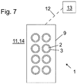
- FIG. 7 illustrates a push-button arrangement 1 comprising a push-button equipment as described above.
- the mounting collar 3 has been installed immovably on a base 9, which is in this case a button panel, the pressel 2 being in the seat of the mounting collar 3 and the pressel 2 in the locked position, wherein in said locked position the collar blocks the pressel 2 from moving in backwards direction orthogonal to the pressing face 6 out from the seat.
- the base is preferably a button panel 9 of an elevator, preferably installed on a wall 11 of the elevator, which wall is a wall of an elevator car or a wall of an elevator landing.
- the button panel 9 is installed on a stand 14 mounted on an elevator landing.
- the push button arrangement is preferably connected over an electrical, wired or wireless, connection 12 with the elevator control unit 13 configured to control movement of the elevator car based on state of the push buttons.
- the push button mentioned in the application is preferably a push-button for actuating an electric switch.
- the arrangement comprises an electric circuit and an electric switch component actuatable to break or connect an electric circuit, and the pressel 2 is arranged to actuate the electric switch component.
- the arrangement preferably, although not necessarily, moreover comprises a light source, such as a LED component, arranged to radiate light outside the push-button, preferably through the collar and/or the pressel. Then, it is preferable that pressel and/or the collar is, or at least comprises, a transparent portion which is visible to the user and which can be illuminated by the light source.
- the collar 3 is preferably a ring around the pressel 2.
- the seat preferably has inner wall w that is circular or at least substantially circular when viewed in said forward direction orthogonal to the pressing face 6.
- the inner wall w can have protrusions protruding towards the center of the circular shape forming the second locking member 8 and the counterpart member 7, for instance.
- the perimeter of the pressing face 6 is preferably circular when viewed in said forward direction orthogonal to the pressing face 6, which facilitates making a structure that is rotatable in a seat s during installation, and pressable such that the pressing face 6 can partially or completely move into the seat s in forward direction orthogonal to the pressing face 6 when pressed by a user.
- circular perimeter is not necessary since the pressing face 6 need not extend into the seat s and thereby it could also have some other shape than the parts located within the seat s.
- the pressel 2 is insertable in the seat s of the mounting collar 3 in forward direction orthogonal to the pressing face 6 without tilting the pressel 2 relative to the mounting collar 3, and thereafter movable in the seat s into the locked position by rotating it in the seat s around the rotational axis x extending in said direction orthogonal to the pressing face 6 without tilting the pressel 2 relative to the mounting collar 3.
- This is advantageous, since thereby the pressel 2 can be installed in the mounting collar 2 without tilting the pressel 2 relative to the mounting collar 3.
- pressel is used for the part of a push button equipment that comprises the pressing face for receiving a press of a user. Also other terms may exist for this part of a push button equipment.
Landscapes
- Engineering & Computer Science (AREA)
- Automation & Control Theory (AREA)
- Computer Networks & Wireless Communication (AREA)
- Physics & Mathematics (AREA)
- General Physics & Mathematics (AREA)
- Mechanical Engineering (AREA)
- Rotary Switch, Piano Key Switch, And Lever Switch (AREA)
- Elevator Control (AREA)
Abstract
Description
- The invention relates to push-buttons, and particularly to push-buttons of an elevator. The elevator is an elevator for transporting passengers and/or goods.
- Conventional push-buttons often comprise a pressel comprising a pressing face for receiving a press of a user, as well as a collar comprising a seat for receiving the pressel.
- There are known push-buttons where installation of the pressel is possible by inserting the pressel in the seat of the mounting collar in forward direction orthogonal to the pressing face for receiving a press of a user. With this kind of front-mounted pressels the equipment usually comprises a return spring mechanism and pressel locking mechanism, which are separate from each other. In prior art, with front-mounted pressels, the locking is done by push of the pressel in direction orthogonal to the pressing face until a fixing clip snaps over a counterpart abutment, wherein the direction of the push in said locking is parallel to the direction of movement of the pressel during actuation by the user. A drawback of this kind of solution is that it tends to cause additional abrasion in button operation. A further drawback of this kind of solution is that the pressels can be removed with relatively minor effort, because the holding ability of the locking depends on the fixing clip strength, which is difficult to make strong without compromises in space-efficiency and/or said abrasion problems. A further drawback of this kind of solution is that the locking mechanism thereof easily increases the overall thickness of the push-button. Even though the increase in thickness may be very slight, it is relevant because the space is already very limited since also a switching element and an illumination element may need to be fitted to cooperate with the pressel and the collar. All that combined with difficult tolerance chains lead to compromises with size or reliability.
- The object of the invention is to provide a new push-button equipment, a pressel therefor and a push-button arrangement. An object is particularly to alleviate one or more of the above defined drawbacks of prior art and/or problems discussed or implied elsewhere in the description.
- A solution is presented, inter alia, by which the overall structure of the push-button is thin. A solution is presented, inter alia, where abrasion caused in button operation can be kept minor. A solution is presented, inter alia, where the holding ability of the locking can be made reliable. A solution is presented, inter alia, where no excessive tilting of the components during installation is necessary which facilitates simplicity of installation from front side of the base, such as a button panel, on which the push-button is to be installed.
- It is brought forward a new push-button equipment comprising a pressel; a mounting collar for being installed on a base, such as a button panel, the mounting collar comprising a seat for receiving the pressel; the pressel comprising a pressing face for receiving a press of a user. The pressel is insertable in the seat of the mounting collar in forward direction orthogonal to the pressing face. The pressel is movable in the seat into a locked position by rotating it in the seat around a rotational axis extending in said direction orthogonal to the pressing face, wherein in said locked position the collar blocks the pressel from moving in backwards direction orthogonal to the pressing face out from the seat. With this solution, one or more of the above mentioned advantages and/or objectives are achieved. This construction makes it possible to install the pressel by push and twist. The overall structure can be thin. Moreover, the amount of abrasion during use can be simply made low due to that locking direction deviates from the installation direction.
- Preferable further features are introduced in the following, which further features can be combined with the push-button equipment individually or in any combination.
- In a preferred embodiment, the collar is arranged to block rotation of the pressel around said rotational axis back from the locked position. This prevents unauthorized removal of the pressel, which for example makes stealing thereof more difficult. It also makes it laborious, or even impossible, to remove the pressel without braking it. Since a new pressel can be mounted without opening the assembly, from maintenance point of view, a worn or a broken pressel can be easily replaced anyways.
- In a preferred embodiment, the pressel comprises a first locking member, and the mounting collar comprises a second locking member, and the pressel inserted in the seat is rotatable in the seat to a locked position around a rotational axis extending in direction orthogonal to the pressing face, such that the first locking member rotates to be positioned in direction of said rotational axis behind the second locking member, whereby in said locked position the second locking member blocks the pressel from moving in backwards direction orthogonal to the pressing face out from the seat. This provides simple locking such that area of surfaces (of the pressel and collar) experiencing abrasion in use, i.e. when the pressel is pressed by the user, can be made only small or even completely eliminated.
- In a preferred embodiment, the pressel is insertable in the seat of the mounting collar in forward direction orthogonal to the pressing face without tilting the pressel relative to the mounting collar.
- In a preferred embodiment, the pressel is movable in the seat into the locked position by rotating it in the seat around a rotational axis extending in said direction orthogonal to the pressing face without tilting the pressel relative to the mounting collar.
- In a preferred embodiment, the push-button equipment, preferably the pressel thereof, comprises a returning spring for returning the pressel in backwards direction orthogonal to the pressing face after the pressel has been pressed by a user.
- In a preferred embodiment, the pressel comprises a returning spring, and when the pressel is in the locked position, it is movable, in particular by press of a user on the pressing face, in the seat in forward direction orthogonal to the pressing face such that the returning spring is elastically deformed, and in backwards direction orthogonal to the pressing face returned by the returning spring.
- In a preferred embodiment, the mounting collar comprises a counterpart member for the returning spring against which the returning spring is tensionable by movement in said forward direction, in particular in said inserting and/or when the pressel is in the locked position.
- In a preferred embodiment, the returning spring is a bendable tongue, tensionable by bending, in particular against said counterpart member.
- In a preferred embodiment, the returning spring is arranged to slide against said counterpart member in said rotation in a tensioned state.
- In a preferred embodiment, the spring comprises a distal end, and the counterpart member comprises an abutment against which the spring is arranged to slide in said rotation in a tensioned state at least until the distal end bypasses an edge of the abutment in direction of said sliding, bypassing of said edge being arranged to allow release of the distal end of the spring to bypass said edge of the abutment in said forward direction to be aligned with the abutment, in particular in tangential direction of the a rotational axis, such that rotation of the spring (and thereby the pressel) in reverse direction is blocked. Thereby, in the solution the returning spring is used for the returning function, and additionally also the function of blocking reverse rotation.
- In a preferred embodiment, the returning spring is a curved bendable tongue extending around said rotational axis, preferably with a constant center of curvature, wherein the center of curvature is at the point of said rotational axis.
- In a preferred embodiment, the returning spring is a bendable tongue helically extending around said rotational axis. Thereby, it can have a thin structure in said direction orthogonal to the pressing face. It is also simple to manufacture.
- In a preferred embodiment, the returning spring extends around said rotational axis an angle which is between 20 and 180 degrees, preferably between 20 and 90 degrees, most preferably between 30 and 70 degrees.
- In a preferred embodiment, the pressel comprises plurality, preferably 2-5 of said first locking members, springs cooperating with 2-5, same number of second locking members and counterpart members comprised in the collar.
- In a preferred embodiment, the thickness of the second locking member in forward direction orthogonal to the pressing face is smaller than the free space on the side of the first locking member towards which the pressing face faces.
- In a preferred embodiment, the pressel comprises a slot on the same side of the first locking member as the pressing face in direction of a rotation axis extending in the direction orthogonal to the pressing face, which slot is open towards tangential direction of the rotational axis extending in direction orthogonal to the pressing face the slot being thereby provided for receiving a second locking member comprised in the mounting collar. The slot is preferably larger in said forward direction orthogonal to the pressing face than the second locking member.
- It is also brought forward a new pressel for a push-button equipment as defined in any of the preceding claims, wherein the pressel comprises a pressing face for receiving a press of a user, a first locking member, and a slot on the same side of the first locking member as the pressing face in direction of a rotation axis extending in the direction orthogonal to the pressing face , which slot is open towards tangential direction of the a rotational axis extending in direction orthogonal to the pressing face, the slot being thereby provided for receiving a second locking member comprised in the mounting collar. With this solution, one or more of the above mentioned advantages and/or objectives are achieved. Preferable further features have been introduced in the following as well as in the paragraphs above, which further features can be combined with the pressel individually or in any combination.
- In a preferred embodiment, the pressel is suitable for being inserted in a seat of a mounting collar in forward direction orthogonal to the pressing face, and movable in the seat into a locked position by rotating it in the seat around a rotational axis extending in said direction orthogonal to the pressing face.
- In a preferred embodiment, the pressel comprises a returning spring.
- In a preferred embodiment, the returning spring is an bendable tongue, tensionable by bending.
- In a preferred embodiment, the returning spring is a curved bendable tongue extending around said rotational axis, preferably with a constant center of curvature, wherein the center of curvature is at the point of said rotational axis.
- In a preferred embodiment, the returning spring is a bendable tongue helically extending around said rotational axis.
- In a preferred embodiment, the pressel is made of plastic.
- In a preferred embodiment, the pressel is a one-piece structure.
- It is also brought forward a new push-button arrangement comprising a push-button equipment according to any of the preceding claims wherein the mounting collar is installed on a base, such as a button panel, the pressel being in the seat of the mounting collar and the pressel in the locked position, wherein in said locked position the collar blocks the pressel from moving in backwards direction orthogonal to the pressing face out from the seat. With this solution, one or more of the above mentioned advantages and/or objectives are achieved. Preferable further features have been introduced in the following as well as in the paragraphs above, which further features can be combined with the arrangement individually or in any combination.
- In a preferred embodiment, the base is a button panel of an elevator, preferably installed on a wall of an elevator, which is a wall of an elevator car or a landing wall, or on a stand mounted on a landing.
- In a preferred embodiment, the push-button arrangement is a push-button arrangement of an elevator.
- In a preferred embodiment, said push button is preferably a push-button for actuating an electric switch.
- In a preferred embodiment, the arrangement comprises an electric circuit and an electric switch component actuatable to break or connect an electric circuit, and the pressel is arranged to actuate the electric switch component.
- In a preferred embodiment, the arrangement moreover comprises a light source, such as a LED component, arranged to radiate light outside the push-button, preferably through the collar and/or the pressel. Then, it is preferable that pressel and/or the collar is, or at least comprises, a transparent portion which is visible to the user and which can be illuminated by the light source.
- In a preferred embodiment, The push button arrangement is preferably connected over an electrical, wired or wireless, connection with the elevator control unit configured to control the elevator car based on state of the push buttons.
- In a preferred embodiment, the collar is a ring that can be positioned around the pressel. The seat preferably has inner wall w that is circular or at least substantially circular when viewed in said forward direction orthogonal to the pressing face. The inner wall w can have protrusions protruding towards the center of the circular shape forming the second locking member and the counterpart member, for instance.
- In a preferred embodiment, the perimeter of the pressing face is circular when viewed in said forward direction orthogonal to the pressing face.
- The elevator is preferably such that it comprises an elevator car vertically movable and configured to serve two or more vertically displaced landings. Preferably, the car has an interior space suitable for receiving a passenger or passengers, and the car can be provided with a door for forming a closed interior space. The elevator is furthermore preferably configured to automatically control movement of the car based on state of push-buttons located at landing(s) and/or inside the elevator car.
- In the following, the present invention will be described in more detail by way of example and with reference to the attached drawings, in which
-
Figure 1 illustrates the back sides of components of a push-button equipment according to a preferred embodiment when still separate from each other. -
Figure 2 illustrates the push-button equipment ofFigure 1 when together. -
Figures 3-6 illustrate partial views of preferred cross-sectional details of the push-button equipment ofFigures 1 and 2 at different stages of installation. -
Figure 7 illustrates a push-button arrangement according to a preferred embodiment. -
Figures 1 and 2 illustrate a push-button equipment, i.e. a set of push-button components, comprising apressel 2 and a mountingcollar 3 for being installed on a base, such as a button panel, the mountingcollar 3 comprising a seat s for receiving thepressel 2. Thepressel 2 is mountable on the base via thecollar 3. Thepressel 2 comprises apressing face 6 for receiving a press of a user. Thepressel 2 is insertable in the seat s of the mountingcollar 3 in forward direction orthogonal to thepressing face 6. Thepressel 2, after being inserted in the mountingcollar 3, is movable in the seat s into a locked position by rotating it in the seat s around a rotational axis x extending in said direction orthogonal to thepressing face 6, wherein in said locked position the collar blocks thepressel 2 from moving in backwards direction orthogonal to thepressing face 6 out from the seat. Thepressing face 6 of thepressel 2 is visible inFigure 2 . The reference number x marks also the direction orthogonal to thepressing face 6 in the Figures. -
Figure 1 illustrates thepressel 2 and a mountingcollar 3 of the push-button equipment from back-side separate from each other.Figure 2 illustrates the push-button equipment ofFigure 1 in a state where thepressel 2 has been inserted in the seat s of the mountingcollar 3 in forward direction orthogonal to thepressing face 6. The arrow illustrates rotation of thepressel 2 inserted in the mountingcollar 3 in the seat s into a locked position around the rotational axis x. - The solution of the preferred embodiment makes it possible to install the
pressel 2 by push and twist. The construction provides that the overall structure is thin. The construction moreover provides that the amount of abrasion during use can be made low due to that locking direction deviates from the installation direction. Area of surfaces (of thepressel 2 and collar 3) experiencing abrasion in use, i.e. when thepressel 2 is pressed by the user, can be made small or even completely eliminated by designing clearances between the components. - In the preferred embodiment, the
pressel 2 comprises afirst locking member 5, and the mountingcollar 3 comprises asecond locking member 8. Thepressel 2 inserted in the seat is rotatable in the seat s to a locked position around the rotational axis x extending in direction orthogonal to thepressing face 6, such that thefirst locking member 5 rotates to be positioned in direction of said rotational axis x behind thesecond locking member 8, whereby in said locked position thesecond locking member 8 blocks thepressel 2 from moving in backwards direction orthogonal to thepressing face 6 out from the seat.Figures 3-6 illustrate preferred details of the push-button equipment ofFigures 1 and 2 at different stages of installation as described hereinafter. -
Figure 3 illustrates thepressel 2 and thecollar 3 prior to inserting thepressel 2 into the seat of thecollar 3. -
Figure 4 illustrates thepressel 2 and thecollar 3 after thepressel 2 has been inserted my moving it in direction orthogonal to thepressing face 6 into the seat s of thecollar 3. The direction in which the pressel is moved in said inserting is referred to as forward direction in the application. When thepressel 2 is in the seat s of thecollar 3, thefirst locking member 5 is deeper in direction of said rotational axis x in the seat s than the second locking member (8, and movable by rotation of the pressel to be positioned in direction of said rotational axis (x) behind thesecond locking member 8. -
Figure 5 illustrates thepressel 2 and thecollar 3 after thepressel 2 has been rotated in the seat to a locked position around the rotational axis x extending in direction orthogonal to thepressing face 6. In this locking position thefirst locking member 5 is positioned in direction of said rotational axis x behind thesecond locking member 8, whereby in said locked position thesecond locking member 8 blocks thepressel 2 from moving in backwards direction orthogonal to thepressing face 6 out from the seat. - Thickness of the
second locking member 8 in forward direction orthogonal to thepressing face 6 is smaller than the free space on the side of thefirst locking member 5 towards which thepressing face 6 faces. Thereby, thepressel 2 is movable in the seat s when said locked position further in said forward direction without being blocked by thesecond locking member 8. Thereby, thepressel 2 can be pressed in said forward direction to actuate an electrical switch (not showed), and particularly to displace a contact member of an electrical switch. When thepressel 2 is in the locked position, it is movable in particular by press of a user on the pressing face, in the seat s in forward direction orthogonal to thepressing face 6.Figure 6 illustrates thepressel 2 and thecollar 3 when thepressel 2, in particular thepressing face 6 thereof, is pressed by a user in said forward direction. Theslot 10 being larger in in the forward direction orthogonal to thepressing face 6 than thesecond locking member 8, in said pressing, a gap g between the first and second lockingmember first locking member 5 as thepressing face 6 in direction orthogonal to thepressing face 6. In said pressing the returning spring is further tensioned and bent against thecounterpart member 7. -
Figures 1 and3-6 moreover illustrate the preferred feature that the push-button equipment, in particular thepressel 2 thereof, comprises a returningspring 4 for returning thepressel 2 in backwards direction orthogonal to the pressing face after thepressel 2 has been pressed by a user. The backwards direction is opposite to the forward direction. The push-button equipment is arranged to operate such that when thepressel 2 is in the locked position, thepressel 2 is movable, in particular by press of a user on thepressing face 6, in the seat s in forward direction orthogonal to thepressing face 6 such that the returningspring 4 is elastically deformed, and in backwards direction orthogonal to the pressing face returned by the returningspring 4. The returningspring 4 is preferably comprised in thepressel 2 as presented in Figures. This is preferable, however not necessary, since alternatively it could be comprised in thecollar 3 or be a component separate from thecollar 3 and thepressel 2. - In the presented embodiments, the mounting
collar 3 comprises acounterpart member 7 for the returningspring 4 comprised in thepressel 2 against which the returningspring 4 is tensionable by movement in said forward direction when thepressel 2 is in the locked position. - As illustrated, the returning
spring 4 is preferably a bendable tongue, tensionable by bending against saidcounterpart member 7 of the mountingcollar 3. - The preferred embodiments moreover show the preferred, although not necessary, further feature that the
collar 3 is arranged to block rotation of thepressel 2 around said rotational axis x back from the locked position. For this purpose, in the preferred embodiments presented, thespring 4 comprises adistal end 4a, and thecounterpart member 7 comprises anabutment 7a against which thespring 4 is arranged to slide in a tensioned state in said rotation of thepressel 2 into a locked position around said rotational axis x at least until thedistal end 4a bypasses anedge 7a' of theabutment 7a in direction of said sliding, bypassing of saidedge 7a' being arranged to allow release of thedistal end 4a of thespring 4 to bypass saidedge 7a' of theabutment 7a in said forward direction to be aligned with theabutment 7a, in particular in tangential direction of the a rotational axis x, such that rotation of the spring 4 (and thereby the pressel) in reverse direction is blocked. - The returning
spring 4 can also be made tensionable by movement in said forward direction in said inserting, which is advantageous since the tension produced in said inserting can be effectively utilized in delimiting the aforementioned rotation to be one-way rotation. - The structure of the returning
spring 4 is more specifically preferably such that it is a curved bendable tongue extending around said rotational axis x, preferably with a constant center of curvature, wherein the center of curvature is at the point of said rotational axis x. This is implemented preferably such that the returningspring 4 is a bendable tongue helically extending around said rotational axis x. Preferably, the returningspring 4 extends around said rotational axis x an angle which is between 20 and 180 degrees, preferably between 20 and 90 degrees, most preferably between 30 and 70 degrees. Thus, thepressel 2 can be simply designed to comprise plurality of saidsprings 4, and the structure thereof can be made elastic enough. In the preferred embodiment, the pressel comprises plurality, preferably 2-5 of said first lockingmembers 5 and springs 4 cooperating with the corresponding number ofsecond locking members 8 andcounterpart members 7, respectively, comprised in thecollar 3. - Hereinafter, preferred details of the
pressel 2 are described. Thepressel 2 is illustrated inFigures 1-7 . Thepressel 2 is preferably particularly such that it comprises apressing face 6 for receiving a press of a user, afirst locking member 5, and aslot 10 on the same side of thefirst locking member 5 as thepressing face 6 in direction of a rotation axis x extending in the direction orthogonal to thepressing face 6, whichslot 10 is open towards tangential direction of the a rotational axis x extending in direction orthogonal to thepressing face 6, theslot 10 being thereby provided for receiving asecond locking member 8 comprised in the mountingcollar 3. Thepressel 2 is suitable for being inserted in a seat s of a mountingcollar 3 in forward direction orthogonal to thepressing face 6, and movable in the seat into a locked position by rotating it in the seat s around a rotational axis x extending in said direction orthogonal to thepressing face 6. - The
pressel 2 comprises a returningspring 4. The returningspring 4 is an bendable tongue, tensionable by bending. The returningspring 4 is a curved bendable tongue extending around said rotational axis x, preferably with a constant center of curvature, wherein the center of curvature is at the point of said rotational axis x. Particularly, the returningspring 4 is a bendable tongue helically extending around said rotational axis x. Preferably, the pressel is made of plastic or at least comprises plastic. Preferably, at least thespring 4 of the pressel is made of plastic. Thepressel 2 can be a one-piece structure made of plastic, but thepressel 2 can of course alternatively be made of metal or a combination of materials such as metal and plastic. Thepressing face 6 is preferably planar or at least substantially planar. It is not necessary that thepressel 2 is a one-piece structure, since thepressel 2 can comprise plurality of parts fixed to each other. -
Figure 7 illustrates a push-button arrangement 1 comprising a push-button equipment as described above. The mountingcollar 3 has been installed immovably on abase 9, which is in this case a button panel, thepressel 2 being in the seat of the mountingcollar 3 and thepressel 2 in the locked position, wherein in said locked position the collar blocks thepressel 2 from moving in backwards direction orthogonal to thepressing face 6 out from the seat. The base is preferably abutton panel 9 of an elevator, preferably installed on a wall 11 of the elevator, which wall is a wall of an elevator car or a wall of an elevator landing. Alternatively, thebutton panel 9 is installed on a stand 14 mounted on an elevator landing. The push button arrangement is preferably connected over an electrical, wired or wireless,connection 12 with theelevator control unit 13 configured to control movement of the elevator car based on state of the push buttons. - The push button mentioned in the application is preferably a push-button for actuating an electric switch. In the aforementioned arrangement, the arrangement comprises an electric circuit and an electric switch component actuatable to break or connect an electric circuit, and the
pressel 2 is arranged to actuate the electric switch component. The arrangement preferably, although not necessarily, moreover comprises a light source, such as a LED component, arranged to radiate light outside the push-button, preferably through the collar and/or the pressel. Then, it is preferable that pressel and/or the collar is, or at least comprises, a transparent portion which is visible to the user and which can be illuminated by the light source. - The
collar 3 is preferably a ring around thepressel 2. The seat preferably has inner wall w that is circular or at least substantially circular when viewed in said forward direction orthogonal to thepressing face 6. The inner wall w can have protrusions protruding towards the center of the circular shape forming thesecond locking member 8 and thecounterpart member 7, for instance. - The perimeter of the
pressing face 6 is preferably circular when viewed in said forward direction orthogonal to thepressing face 6, which facilitates making a structure that is rotatable in a seat s during installation, and pressable such that thepressing face 6 can partially or completely move into the seat s in forward direction orthogonal to thepressing face 6 when pressed by a user. However, circular perimeter is not necessary since thepressing face 6 need not extend into the seat s and thereby it could also have some other shape than the parts located within the seat s. - In the preferred embodiments presented, the
pressel 2 is insertable in the seat s of the mountingcollar 3 in forward direction orthogonal to thepressing face 6 without tilting thepressel 2 relative to the mountingcollar 3, and thereafter movable in the seat s into the locked position by rotating it in the seat s around the rotational axis x extending in said direction orthogonal to thepressing face 6 without tilting thepressel 2 relative to the mountingcollar 3. This is advantageous, since thereby thepressel 2 can be installed in the mountingcollar 2 without tilting thepressel 2 relative to the mountingcollar 3. - In the application, term pressel is used for the part of a push button equipment that comprises the pressing face for receiving a press of a user. Also other terms may exist for this part of a push button equipment.
- It is to be understood that the above description and the accompanying Figures are only intended to teach the best way known to the inventors to make and use the invention. It will be apparent to a person skilled in the art that the inventive concept can be implemented in various ways. The above-described embodiments of the invention may thus be modified or varied, without departing from the invention, as appreciated by those skilled in the art in light of the above teachings. It is therefore to be understood that the invention and its embodiments are not limited to the examples described above but may vary within the scope of the claims.
Claims (15)
- A push-button equipment comprisinga pressel (2);a mounting collar (3) for being installed on a base, such as a button panel, the mounting collar (3) comprising a seat (s) for receiving the pressel (2);the pressel (2) comprising a pressing face (6) for receiving a press of a user,the pressel (2) being insertable in the seat (s) of the mounting collar in forward direction orthogonal to the pressing face (6), characterized in that the pressel (2) is movable in the seat into a locked position by rotating it in the seat around a rotational axis (x) extending in said direction orthogonal to the pressing face (6), wherein in said locked position the collar blocks the pressel (2) from moving in backwards direction orthogonal to the pressing face (6) out from the seat (s).
- A push-button equipment according claim 1, wherein the collar (3) is arranged to block rotation of the pressel (2) around said rotational axis (x) back from the locked position.
- A push-button equipment according to any of the preceding claims, wherein the pressel (2) comprises a first locking member (5), and the mounting collar (3) comprises a second locking member (8), and the pressel (2) inserted in the seat (s) is rotatable in the seat (s) to a locked position around a rotational axis (x) extending in direction orthogonal to the pressing face (6), such that the first locking member (5) rotates to be positioned in direction of said rotational axis (x) behind the second locking member (8), whereby in said locked position the second locking member (8) blocks the pressel (2) from moving in backwards direction (x) orthogonal to the pressing face (6) out from the seat (s).
- A push-button equipment according to any of the preceding claims, wherein push-button (1) equipment, preferably the pressel (2) thereof, comprises a returning spring (4) for returning the pressel (2) in backwards direction orthogonal to the pressing face (6) after the pressel (2) has been pressed by a user.
- A push-button equipment according to any of the preceding claims, wherein the pressel (2) comprises a returning spring (4), and when the pressel (2) is in the locked position, it is movable in particular by press of a user on the pressing face (6), in the seat (s) in the forward direction orthogonal to the pressing face (6) such that the returning spring (4) is elastically deformed, and in backwards direction orthogonal to the pressing face (6) returned by the returning spring (4).
- A push-button equipment according to any of the preceding claims 4-5, wherein the mounting collar (3) comprises a counterpart member (7) for the returning spring (4) against which the returning spring (4) is tensionable by movement in said forward direction, in particular in said inserting and/or when the pressel (2) is in the locked position.
- A push-button equipment according to any of the preceding claims 4-6, wherein the returning spring (4) is a bendable tongue, tensionable by bending, in particular against said counterpart member (7).
- A push-button equipment according to any of the preceding claims 4-7, wherein the returning spring (4) is in said rotation arranged to slide against said counterpart member (7) in a tensioned state.
- A push-button equipment according to any of the preceding claims 4-8, wherein the returning spring (4) comprises a distal end (4a), and the counterpart member (7) comprises an abutment (7a) against which the returning spring (4) is arranged to slide in said rotation in a tensioned state at least until the distal end (4a) bypasses an edge (7a') of the abutment (7a) in direction of said sliding, said bypassing of said edge (7a') being arranged to allow release of the distal end (4a) of the returning spring (4) to bypass said edge (7a') of the abutment (7a) in said forward direction to be aligned with the abutment (7a), in particular in tangential direction of the a rotational axis (x), such that rotation of the spring (4) in reverse direction is blocked.
- A push-button equipment according to any of the preceding claims 4-9 wherein the returning spring (4) is a bendable tongue helically extending around said rotational axis (x).
- A push-button equipment according to any of the preceding claims 3-10 wherein the pressel (2) comprises a slot (10) on the same side of the first locking member (5) as the pressing face (6) in direction of a rotation axis (x) extending in the direction orthogonal to the pressing face (6), which slot (10) is open towards tangential direction of the a rotational axis (x) extending in direction orthogonal to the pressing face (6), the slot (10) being thereby provided for receiving a second locking member (8) comprised in the mounting collar (3), the slot (10) preferably being larger in the forward direction orthogonal to the pressing face (6) than the second locking member (8).
- A pressel (2) for a push-button equipment as defined in any of the preceding claims 1-11, wherein the pressel (2) comprises
a pressing face (6) for receiving a press of a user;
a first locking member (5); and
a slot (10) on the same side of the first locking member (5) as the pressing face (6) in direction of a rotation axis (x) extending in the direction orthogonal to the pressing face (6), which slot (10) is open towards tangential direction of the rotational axis (x) extending in direction orthogonal to the pressing face (6), the slot (10) being thereby provided for receiving a second locking member (8) comprised in the mounting collar (3). - A pressel (2) according to any of the preceding claims, wherein the pressel (2) is suitable for being inserted in a seat (s) of a mounting collar (3) in forward direction orthogonal to the pressing face (6), and movable in the seat (s) into a locked position by rotating it in the seat (s) around a rotational axis (x) extending in said direction orthogonal to the pressing face (6).
- A pressel (2) or a push-button equipment according to any of the preceding claims, wherein the pressel (2) comprises a returning spring (4).
- A push-button arrangement (1) comprising a push-button equipment according to any of the preceding claims wherein the mounting collar (3) is installed on a base (9), such as a button panel, the pressel (2) being in the seat (s) of the mounting collar (3), and the pressel (2) being in the locked position, wherein in said locked position the mounting collar (3) blocks the pressel (2) from moving in backwards direction orthogonal to the pressing face (6) out from the seat (s).
Priority Applications (3)
| Application Number | Priority Date | Filing Date | Title |
|---|---|---|---|
| EP18153809.1A EP3518264A1 (en) | 2018-01-29 | 2018-01-29 | Push-button equipment, pressel therefor and push-button arrangement |
| US16/213,430 US10831229B2 (en) | 2018-01-29 | 2018-12-07 | Push-button equipment, pressel therefor and push-button arrangement |
| CN201910004012.4A CN110098077A (en) | 2018-01-29 | 2019-01-03 | Button devices, suspension type button and PBU pushbutton unit for button devices |
Applications Claiming Priority (1)
| Application Number | Priority Date | Filing Date | Title |
|---|---|---|---|
| EP18153809.1A EP3518264A1 (en) | 2018-01-29 | 2018-01-29 | Push-button equipment, pressel therefor and push-button arrangement |
Publications (1)
| Publication Number | Publication Date |
|---|---|
| EP3518264A1 true EP3518264A1 (en) | 2019-07-31 |
Family
ID=61074366
Family Applications (1)
| Application Number | Title | Priority Date | Filing Date |
|---|---|---|---|
| EP18153809.1A Withdrawn EP3518264A1 (en) | 2018-01-29 | 2018-01-29 | Push-button equipment, pressel therefor and push-button arrangement |
Country Status (3)
| Country | Link |
|---|---|
| US (1) | US10831229B2 (en) |
| EP (1) | EP3518264A1 (en) |
| CN (1) | CN110098077A (en) |
Cited By (1)
| Publication number | Priority date | Publication date | Assignee | Title |
|---|---|---|---|---|
| WO2023052266A1 (en) * | 2021-09-30 | 2023-04-06 | Inventio Ag | Elevator push button device |
Families Citing this family (4)
| Publication number | Priority date | Publication date | Assignee | Title |
|---|---|---|---|---|
| US10519003B2 (en) * | 2015-03-13 | 2019-12-31 | Mitsubishi Electric Corporation | Elevator operation panel |
| US11835981B2 (en) * | 2019-04-04 | 2023-12-05 | Kortek Corporation | Operating device |
| WO2021240738A1 (en) * | 2020-05-28 | 2021-12-02 | オムロン株式会社 | Push-button switch, push-button switch unit, operating unit, and game machine |
| CN115512989A (en) * | 2022-09-13 | 2022-12-23 | 上海飞科电器股份有限公司 | Lock catch mechanism |
Citations (5)
| Publication number | Priority date | Publication date | Assignee | Title |
|---|---|---|---|---|
| FR2498272A1 (en) * | 1981-01-20 | 1982-07-23 | Itt | Bayonet coupling nut suitable for electrical connectors - has slot-forming elements spaced and mounted in cylindrical nut body |
| US5144103A (en) * | 1990-03-09 | 1992-09-01 | Canon Kabushiki Kaisha | Key switch |
| JP2001052558A (en) * | 1999-08-03 | 2001-02-23 | Shu Plans Work:Kk | Switch device |
| US20110094869A1 (en) * | 2009-10-23 | 2011-04-28 | Hon Fu Jin Precision Industry (Shenzhen) Co., Ltd. | Power button assembly and electronic device using the same |
| US20150023759A1 (en) * | 2013-07-17 | 2015-01-22 | II James W. Klopfenstein | Fastener for Attaching Objects to Channeled Members |
Family Cites Families (3)
| Publication number | Priority date | Publication date | Assignee | Title |
|---|---|---|---|---|
| FI6660U1 (en) * | 2005-01-21 | 2005-04-27 | Polar Electro Oy | Fast fixing system, quick fixing kit and portable electronic device |
| FR2948641B1 (en) * | 2009-07-28 | 2016-02-12 | Rexam Dispensing Sys | SYSTEM FOR FIXING A DISTRIBUTION PUMP ON THE BOTTOM OF A BOTTLE CONTAINING A FLUID PRODUCT |
| US8944838B2 (en) * | 2013-04-10 | 2015-02-03 | Tyco Electronics Corporation | Connector with locking ring |
-
2018
- 2018-01-29 EP EP18153809.1A patent/EP3518264A1/en not_active Withdrawn
- 2018-12-07 US US16/213,430 patent/US10831229B2/en not_active Expired - Fee Related
-
2019
- 2019-01-03 CN CN201910004012.4A patent/CN110098077A/en active Pending
Patent Citations (5)
| Publication number | Priority date | Publication date | Assignee | Title |
|---|---|---|---|---|
| FR2498272A1 (en) * | 1981-01-20 | 1982-07-23 | Itt | Bayonet coupling nut suitable for electrical connectors - has slot-forming elements spaced and mounted in cylindrical nut body |
| US5144103A (en) * | 1990-03-09 | 1992-09-01 | Canon Kabushiki Kaisha | Key switch |
| JP2001052558A (en) * | 1999-08-03 | 2001-02-23 | Shu Plans Work:Kk | Switch device |
| US20110094869A1 (en) * | 2009-10-23 | 2011-04-28 | Hon Fu Jin Precision Industry (Shenzhen) Co., Ltd. | Power button assembly and electronic device using the same |
| US20150023759A1 (en) * | 2013-07-17 | 2015-01-22 | II James W. Klopfenstein | Fastener for Attaching Objects to Channeled Members |
Cited By (2)
| Publication number | Priority date | Publication date | Assignee | Title |
|---|---|---|---|---|
| WO2023052266A1 (en) * | 2021-09-30 | 2023-04-06 | Inventio Ag | Elevator push button device |
| CN118043275A (en) * | 2021-09-30 | 2024-05-14 | 因温特奥股份公司 | Elevator button device |
Also Published As
| Publication number | Publication date |
|---|---|
| US20190235563A1 (en) | 2019-08-01 |
| US10831229B2 (en) | 2020-11-10 |
| CN110098077A (en) | 2019-08-06 |
Similar Documents
| Publication | Publication Date | Title |
|---|---|---|
| US10831229B2 (en) | Push-button equipment, pressel therefor and push-button arrangement | |
| US10590681B2 (en) | Door latch system | |
| US6765472B2 (en) | Security system for a motor vehicle opening leaf equipped with switches | |
| CN105377648A (en) | Hand brake valve for braking systems of pneumatically braked motor vehicles | |
| US9589741B2 (en) | Pressure-actuated safety switch with monitoring function | |
| US7798291B2 (en) | Emergency device for installing in an elevator car of an elevator installation | |
| JP4746625B2 (en) | Vehicle liners and interior lighting systems and fixtures | |
| EP0694221B1 (en) | A power take-off adaptor for a conductor rail | |
| US4382320A (en) | Seat belt buckle | |
| EP1750292A1 (en) | Automotive air conditioning switch system | |
| HK40012641A (en) | Push-button equipment, pressel therefor and push-button arrangement | |
| EP1947667B1 (en) | Switch | |
| CN107697148B (en) | steering wheel for vehicle | |
| CN110644874B (en) | Handle device for door lock | |
| US1775768A (en) | Wall-lamp attachment | |
| US20100321944A1 (en) | Detent spring and end cap structures for a visor vanity | |
| JP6381258B2 (en) | Ceiling access door | |
| US8842409B2 (en) | Electronic control panel with protection against electrostatic discharges | |
| JP2003178643A (en) | Push button switch | |
| US6724888B2 (en) | Call transmitter for the input of control commands, particularly for an elevator installation | |
| US10926697B2 (en) | Switch structure | |
| EP1557853A1 (en) | Push button switch for vehicle | |
| EP2410657A1 (en) | Tilting operation type input device | |
| GB2310958A (en) | Lock for a safety belt | |
| EP3925828B1 (en) | Overhead console |
Legal Events
| Date | Code | Title | Description |
|---|---|---|---|
| PUAI | Public reference made under article 153(3) epc to a published international application that has entered the european phase |
Free format text: ORIGINAL CODE: 0009012 |
|
| STAA | Information on the status of an ep patent application or granted ep patent |
Free format text: STATUS: THE APPLICATION HAS BEEN PUBLISHED |
|
| AK | Designated contracting states |
Kind code of ref document: A1 Designated state(s): AL AT BE BG CH CY CZ DE DK EE ES FI FR GB GR HR HU IE IS IT LI LT LU LV MC MK MT NL NO PL PT RO RS SE SI SK SM TR |
|
| AX | Request for extension of the european patent |
Extension state: BA ME |
|
| STAA | Information on the status of an ep patent application or granted ep patent |
Free format text: STATUS: REQUEST FOR EXAMINATION WAS MADE |
|
| 17P | Request for examination filed |
Effective date: 20200115 |
|
| RBV | Designated contracting states (corrected) |
Designated state(s): AL AT BE BG CH CY CZ DE DK EE ES FI FR GB GR HR HU IE IS IT LI LT LU LV MC MK MT NL NO PL PT RO RS SE SI SK SM TR |
|
| GRAP | Despatch of communication of intention to grant a patent |
Free format text: ORIGINAL CODE: EPIDOSNIGR1 |
|
| STAA | Information on the status of an ep patent application or granted ep patent |
Free format text: STATUS: GRANT OF PATENT IS INTENDED |
|
| INTG | Intention to grant announced |
Effective date: 20200423 |
|
| GRAJ | Information related to disapproval of communication of intention to grant by the applicant or resumption of examination proceedings by the epo deleted |
Free format text: ORIGINAL CODE: EPIDOSDIGR1 |
|
| STAA | Information on the status of an ep patent application or granted ep patent |
Free format text: STATUS: REQUEST FOR EXAMINATION WAS MADE |
|
| INTC | Intention to grant announced (deleted) | ||
| GRAP | Despatch of communication of intention to grant a patent |
Free format text: ORIGINAL CODE: EPIDOSNIGR1 |
|
| STAA | Information on the status of an ep patent application or granted ep patent |
Free format text: STATUS: GRANT OF PATENT IS INTENDED |
|
| INTG | Intention to grant announced |
Effective date: 20201006 |
|
| STAA | Information on the status of an ep patent application or granted ep patent |
Free format text: STATUS: THE APPLICATION IS DEEMED TO BE WITHDRAWN |
|
| 18D | Application deemed to be withdrawn |
Effective date: 20210217 |