EP3518250B1 - A structural component for a nuclear reactor, and a fuel assembly - Google Patents
A structural component for a nuclear reactor, and a fuel assembly Download PDFInfo
- Publication number
- EP3518250B1 EP3518250B1 EP18153880.2A EP18153880A EP3518250B1 EP 3518250 B1 EP3518250 B1 EP 3518250B1 EP 18153880 A EP18153880 A EP 18153880A EP 3518250 B1 EP3518250 B1 EP 3518250B1
- Authority
- EP
- European Patent Office
- Prior art keywords
- structural component
- metallic alloy
- alloy
- molar
- elements
- Prior art date
- Legal status (The legal status is an assumption and is not a legal conclusion. Google has not performed a legal analysis and makes no representation as to the accuracy of the status listed.)
- Active
Links
Images

Classifications
-
- G—PHYSICS
- G21—NUCLEAR PHYSICS; NUCLEAR ENGINEERING
- G21C—NUCLEAR REACTORS
- G21C3/00—Reactor fuel elements and their assemblies; Selection of substances for use as reactor fuel elements
- G21C3/02—Fuel elements
- G21C3/04—Constructional details
- G21C3/06—Casings; Jackets
- G21C3/07—Casings; Jackets characterised by their material, e.g. alloys
-
- Y—GENERAL TAGGING OF NEW TECHNOLOGICAL DEVELOPMENTS; GENERAL TAGGING OF CROSS-SECTIONAL TECHNOLOGIES SPANNING OVER SEVERAL SECTIONS OF THE IPC; TECHNICAL SUBJECTS COVERED BY FORMER USPC CROSS-REFERENCE ART COLLECTIONS [XRACs] AND DIGESTS
- Y02—TECHNOLOGIES OR APPLICATIONS FOR MITIGATION OR ADAPTATION AGAINST CLIMATE CHANGE
- Y02E—REDUCTION OF GREENHOUSE GAS [GHG] EMISSIONS, RELATED TO ENERGY GENERATION, TRANSMISSION OR DISTRIBUTION
- Y02E30/00—Energy generation of nuclear origin
- Y02E30/30—Nuclear fission reactors
Definitions
- the present invention refers generally to structural components for the core of nuclear fission reactors, for instance water cooled reactors, including light water reactors such as Boiling Water reactors, BWR, and Pressurized Water reactors, PWR.
- the structural component is also suitable for use in the next generation reactors, both fast reactors, such as lead-fast reactors, and thermal reactors.
- the present invention refers to a structural component configured to be used in the core of a nuclear fission reactor according to the preamble of claim 1.
- the present invention also refers to a fuel assembly for a nuclear fission reactor, comprising a structural component.
- EP 40901 discloses an austenitic alloy for use in a fuel cladding or possibly in a fuel duct.
- the austenitic alloy comprises three main elements each with a concentration of 1-50%.
- WO 2005/038061 discloses an alloy suitable as coating material for a machinery member in a corrosive environment.
- the alloy is a Ni-Cr-Mo-V-C-based alloy.
- US 4,144,059 refers generally to long range ordered alloys of the transition metals V, Ni, Co and Fe. It is mentioned that the V-Fe-Co-Ni alloy is particular useful in components such as nuclear reactor fuel cladding.
- US 3,677,723 discloses a composite material for cladding nuclear fuel elements comprising a vanadium base alloy material.
- the alloy comprises V, Ti, Nb(Colombium), Zr, Cr, Mo, Ta, W, Al, Ni, Be, Si, Fe, Yt.
- US 2018/025794 discloses a method for coating the substrate of a component for use in a water cooled nuclear reactor to provide a barrier against corrosion.
- the method includes providing a zirconium alloy substrate; and coating the substrate with particles selected from the group consisting of metal oxides, metal nitrides, FeCrAl, FeCrAlY, and high entropy alloys.
- US 2016/0326616 discloses an entropy-controlled solid solution matrix BCC alloy having strong resistance to high-temperature neutron radiation damage.
- the entropy-controlled solid solution matrix BCC alloy includes three or more multicomponent main elements selected from the element group consisting of Zr, Al, Nb, Mo, Cr, V, and Ti selected based on a neutron absorption cross-sectional area and a mixing enthalpy. Each of the elements is included in an amount of 5 to 35 at %, and the entropy-controlled solid solution matrix BCC alloy is a BCC-structure solid solution matrix alloy in a medium-entropy to high-entropy state.
- the object of the present invention is to provide an improved structural component configured for being used in the core of nuclear fission reactors.
- it is aimed at a structural component that is improved with respect to hardness, ductility, creep, oxidation and hydrogen absorption.
- the structural component initially defined which is characterized in that the concentration of each of the principal elements in the metallic alloy is at most 50 molar-% and at least 10 molar-%, and that the metallic alloy consists of one of Zr 2 TiNbV, ZrTiNbVMo, ZrCrNbMo, MoNbTiZr and NbTaVZr.
- Such metallic alloys are frequently called high entropy alloys, HEAs.
- HEAs high entropy alloys
- Ni-alloys, and zirconium-based alloys such a metallic alloy has no overall dominant element, i.e. no element with a concentration of more than 50 molar-% of the alloy.
- Each of the principal elements may thus have a concentration in the metallic alloy of at least 10 molar-% and at most 50 molar-%.
- the metallic alloys are generally hard, ductile, and as a result of their structure have a high resiliency to creep, oxidation and hydrogen absorption effects.
- the metallic alloys are highly tailorable to permit achievement of specific stiffness, density and other properties.
- the concentration of each of the principal elements in the metallic alloy is at most 50 molar-% and at least 15 molar-%.
- the concentration of each of the principal elements in the metallic alloy is at most 50 molar-% and at least 18 molar-%.
- the metallic alloy has a homogenous microstructure.
- the metallic alloy consists of one of Zr 2 TiNbV, ZrTiNbVMo, ZrCrNbMo, MoNbTiZr and NbTaVZr.
- metallic alloys all have the advantageous properties mentioned above, and thus are suitable in various nuclear reactor core components.
- metallic alloys, containing or being based on Zr, Ti, and V, are expected to have extremely advantageous properties whilst maintaining a relatively low neutron cross-section, making them suitable for nuclear reactor applications.
- the possible residual elements comprise at least one of the elements C, O, N and Si.
- the residual elements may form alloying elements further improving the properties of the metallic alloy, for instance changing the mechanical properties, contributing to precipitation hardening etc.
- the possible residual elements together have a total concentration which is at most 1 molar-% of the metallic alloy.
- the metallic alloy has a body centered cubic structure.
- the structural component is a cladding tube for a fuel rod of a fuel assembly.
- the cladding tube is made of the metallic alloy.
- a part of the cladding tube is made of the metallic alloy.
- the cladding tube may comprise a surface layer of the metallic alloy.
- the surface layer may be an outer and/or inner surface layer.
- the metallic alloy consists of one of Zr 2 TiNbV, ZrTiNbVMo, ZrCrNbMo, MoNbTiZr and NbTaVZr. These metallic alloys are suitable for forming a cladding tube or a surface layer or coating of a cladding tube.
- the structural component is a spacer for retaining fuel rods in a bundle of fuel rods in a fuel assembly.
- the spacer is made of the metallic alloy.
- a part of the spacer is made of the metallic alloy.
- the part of the spacer may comprise a surface layer of the metallic alloy, and/or one or more spring members of the metallic alloy.
- the object of the invention is also achieved by the fuel assembly initially defined, which comprises a structural component as defined above or a plurality of structural components as defined above, in particular structural components in the form of cladding tubes and/or spacers as defined above.
- Fig. 1 discloses a fuel assembly 1 configured for being inserted into and used in the core of a nuclear fission reactor, in particular in a Light Water Reactor, LWR, such as a Boiling Water Reactor, BWR, or a Pressurized Water reactor, PWR.
- LWR Light Water Reactor
- BWR Boiling Water Reactor
- PWR Pressurized Water reactor
- the fuel assembly 1 may also be suitable for use in the core of the next generation reactors, including fast reactors, such as lead-fast reactors, and thermal reactors.
- the fuel assembly 1 comprises a bottom member 2, a top member 3 and a plurality of elongated fuel rods 4 extending between the bottom member 2 and the top member 3.
- the fuel rods 4 are maintained in their positions in the fuel assembly 1 by means of a plurality of spacers 5.
- the fuel assembly 1 may, for instance when to be used in a BWR, comprise a flow channel or fuel box 5 indicated by dashed lines 6 and surrounding the fuel rods 4.
- Fig 2 discloses one of the fuel rods 4 of the fuel assembly 1 of Fig 1 .
- Each of the fuel rod 4 may comprise a nuclear fuel, for instance in the form of a plurality of sintered nuclear fuel pellets 10, and a cladding tube 11 enclosing the nuclear fuel, in this case the nuclear fuel pellets 10.
- the fuel rod 4 comprises a bottom plug 12 sealing a lower end of the cladding tube 11, and a top plug 13 sealing an upper end of the cladding tube 11.
- the nuclear fuel pellets 10 are arranged in a pile in an inner space 14 of the cladding tube 11.
- the cladding tube 11 encloses the fuel pellets 10 and a gas in the inner space 14.
- a spring member 15 is arranged in an upper plenum 16 of the inner space 14 between the pile of nuclear fuel pellets 10 and the top plug 13. The spring member 15 presses the pile of nuclear fuel pellets 10 against the bottom plug 12.
- Each of the spacers 5 as well as each of the cladding tubes 11 constitutes a structural component of the fuel assembly 1 to be inserted into the core of the nuclear fission reactor.
- Each of the structural components i.e. the spacers 5 and/or the cladding tubes 11, may comprise at least a part 17 of a metallic alloy that is a multi-principal-element alloy.
- the multi-principal-element consists of at least four principal elements and of possible residual elements.
- the concentration of each of the principal elements in the metallic alloy is at most 50 molar-% and at least 10 molar-%.
- the concentration of each of the principal elements in the metallic alloy may be at most 50 molar-% and at least 15 molar-%, or at most 50 molar-% and at least 18 molar-%.
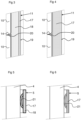
- Fig 3 discloses a first embodiment, according to which the part 17 of the metallic alloy forms a surface coating of the cladding tube 11.
- the surface coating may be an outer surface coating as shown in Fig 3 , and/or an inner surface coating of the cladding tube 11.
- the outer surface coating may form the outer surface 19 of the cladding tube 11 and the fuel rod 4.
- the inner surface coating may form the inner surface 20 of the cladding tube 11, which is turned towards the inner space 14.
- the part 17 is applied to base part 18 of the cladding tube 11.
- the base part 18 may be made of any suitable cladding material, for instance a zirconium-based alloy.
- Fig 4 discloses a second embodiment, according to which the part 17 of the metallic alloy forms the cladding tube 11, i.e. the cladding tube 11 is made of, or consists of, the metallic alloy.
- the metallic alloy may form the outer surface 19 and the inner surface 20 of the cladding tube 11.
- Fig 5 discloses a third embodiment, according to which the part 17 of the metallic alloy forms a surface coating of the spacer 5.
- the surface coating may be an outer surface coating of the spacer 5 and form an outer surface of the whole spacer 5 as is indicated in Fig 5 .
- the part 17 is applied to base part 18 of the spacer 5.
- the base part 18 may be made of any suitable cladding material, for instance a nickel-chromium-based alloy, such as Inconel, or a zirconium-based alloy.
- the spacer 5 may comprise spring members 21 abutting the fuel rods 4.
- the spring members 21 of the spacer of the third embodiment may be made of the metallic alloy, or the metallic alloy may form a surface coating of the spring member 21 as disclosed in Fig 5 .
- Fig 6 discloses a fourth embodiment, according to which the part 17 of the metallic alloy forms the spacer 5, i.e. the spacer 5 is made of, or consists of, the metallic alloy.
- the spacer 5 of the fourth embodiment may also comprise spring members 21 abutting the fuel rods 4 and being made of the metallic alloy.
- the metallic alloy which has no overall dominant element, is frequently called a high entropy alloy, HEA.
- the metallic alloy may have a homogenous microstructure.
- the metallic alloy may have a body centered cubic, BCC, structure.
- the at least four principal elements of the metallic alloy are chosen from the group consisting of Zr, Ti Nb, V, Mo Ta, and Cr.
- the metallic alloy may consist of four or five principal elements chosen from this group.
- the metallic alloy may consist of one of the following: Zr 2 TiNbV, ZrTiNbVMo, ZrCrNbMo, MoNbTiZr, and NbTaVZr.
- the possible residual elements that may be comprised by the metallic alloy comprise at least one of the elements C, O, N and Si. These elements may form alloying elements, which may improve the properties of the metallic alloy further. Preferably, the total concentration of the possible residual elements may be at most 1 molar-% of the metallic alloy.
- the principal elements of the metallic alloy may be chosen from the group consisting of Zr, Ti, Nb, V, Mo and Ta, which are all suitable for being contained in metallic alloys for cladding tubes.
- a first one of the principal elements may be Zr
- a second one of the principal elements may be Nb.
- the metallic alloy may preferably consist of one of Zr 2 TiNbV, ZrTiNbVMo, ZrCrNbMo, MoNbTiZr and NbTaVZr. These metallic alloys are advantageous for cladding tubes, for instance with regard to a relatively low neutron cross-section.
- a principal element of the metallic alloy may be Cr.
- These metallic alloys are advantageous for spacers. They may form the space, a surface layer of the spacer or a spring member of the spacer.
- these two metallic alloys also may form a surface layer or coating of a cladding tube 11, such as the part 17 of the first embodiment.
Landscapes
- Engineering & Computer Science (AREA)
- Physics & Mathematics (AREA)
- Metallurgy (AREA)
- Plasma & Fusion (AREA)
- General Engineering & Computer Science (AREA)
- High Energy & Nuclear Physics (AREA)
- Monitoring And Testing Of Nuclear Reactors (AREA)
Description
- The present invention refers generally to structural components for the core of nuclear fission reactors, for instance water cooled reactors, including light water reactors such as Boiling Water reactors, BWR, and Pressurized Water reactors, PWR. The structural component is also suitable for use in the next generation reactors, both fast reactors, such as lead-fast reactors, and thermal reactors.
- Specifically, the present invention refers to a structural component configured to be used in the core of a nuclear fission reactor according to the preamble of
claim 1. - The present invention also refers to a fuel assembly for a nuclear fission reactor, comprising a structural component.
-
EP 40901 -
WO 2005/038061 discloses an alloy suitable as coating material for a machinery member in a corrosive environment. The alloy is a Ni-Cr-Mo-V-C-based alloy. -
US 4,144,059 refers generally to long range ordered alloys of the transition metals V, Ni, Co and Fe. It is mentioned that the V-Fe-Co-Ni alloy is particular useful in components such as nuclear reactor fuel cladding. -
US 3,677,723 discloses a composite material for cladding nuclear fuel elements comprising a vanadium base alloy material. The alloy comprises V, Ti, Nb(Colombium), Zr, Cr, Mo, Ta, W, Al, Ni, Be, Si, Fe, Yt. -
US 2018/025794 discloses a method for coating the substrate of a component for use in a water cooled nuclear reactor to provide a barrier against corrosion. The method includes providing a zirconium alloy substrate; and coating the substrate with particles selected from the group consisting of metal oxides, metal nitrides, FeCrAl, FeCrAlY, and high entropy alloys. -
US 2016/0326616 discloses an entropy-controlled solid solution matrix BCC alloy having strong resistance to high-temperature neutron radiation damage. The entropy-controlled solid solution matrix BCC alloy includes three or more multicomponent main elements selected from the element group consisting of Zr, Al, Nb, Mo, Cr, V, and Ti selected based on a neutron absorption cross-sectional area and a mixing enthalpy. Each of the elements is included in an amount of 5 to 35 at %, and the entropy-controlled solid solution matrix BCC alloy is a BCC-structure solid solution matrix alloy in a medium-entropy to high-entropy state. - The object of the present invention is to provide an improved structural component configured for being used in the core of nuclear fission reactors. In particular, it is aimed at a structural component that is improved with respect to hardness, ductility, creep, oxidation and hydrogen absorption.
- This object is achieved by the structural component initially defined, which is characterized in that the concentration of each of the principal elements in the metallic alloy is at most 50 molar-% and at least 10 molar-%, and that the metallic alloy consists of one of Zr2TiNbV, ZrTiNbVMo, ZrCrNbMo, MoNbTiZr and NbTaVZr.
- Such metallic alloys are frequently called high entropy alloys, HEAs. In contrast to steel, Ni-alloys, and zirconium-based alloys, such a metallic alloy has no overall dominant element, i.e. no element with a concentration of more than 50 molar-% of the alloy. Each of the principal elements may thus have a concentration in the metallic alloy of at least 10 molar-% and at most 50 molar-%.
- The metallic alloys are generally hard, ductile, and as a result of their structure have a high resiliency to creep, oxidation and hydrogen absorption effects. The metallic alloys are highly tailorable to permit achievement of specific stiffness, density and other properties.
- According to an embodiment of the invention, the concentration of each of the principal elements in the metallic alloy is at most 50 molar-% and at least 15 molar-%.
- According to an embodiment of the invention, the concentration of each of the principal elements in the metallic alloy is at most 50 molar-% and at least 18 molar-%.
- According to an embodiment of the invention, the metallic alloy has a homogenous microstructure.
- According to the invention, the metallic alloy consists of one of Zr2TiNbV, ZrTiNbVMo, ZrCrNbMo, MoNbTiZr and NbTaVZr.
- These metallic alloys all have the advantageous properties mentioned above, and thus are suitable in various nuclear reactor core components. For instance metallic alloys, containing or being based on Zr, Ti, and V, are expected to have extremely advantageous properties whilst maintaining a relatively low neutron cross-section, making them suitable for nuclear reactor applications.
- According to an embodiment of the invention, the possible residual elements comprise at least one of the elements C, O, N and Si. The residual elements may form alloying elements further improving the properties of the metallic alloy, for instance changing the mechanical properties, contributing to precipitation hardening etc.
- According to an embodiment of the invention, the possible residual elements together have a total concentration which is at most 1 molar-% of the metallic alloy.
- According to an embodiment of the invention, the metallic alloy has a body centered cubic structure.
- According to an embodiment of the invention, the structural component is a cladding tube for a fuel rod of a fuel assembly.
- According to an embodiment of the invention, the cladding tube is made of the metallic alloy.
- According to an embodiment of the invention, a part of the cladding tube is made of the metallic alloy. For instance, the cladding tube may comprise a surface layer of the metallic alloy. The surface layer may be an outer and/or inner surface layer.
- According to the invention, the metallic alloy consists of one of Zr2TiNbV, ZrTiNbVMo, ZrCrNbMo, MoNbTiZr and NbTaVZr. These metallic alloys are suitable for forming a cladding tube or a surface layer or coating of a cladding tube.
- According to an embodiment of the invention, the structural component is a spacer for retaining fuel rods in a bundle of fuel rods in a fuel assembly.
- According to an embodiment of the invention, the spacer is made of the metallic alloy.
- According to an embodiment of the invention, a part of the spacer is made of the metallic alloy. For instance, the part of the spacer may comprise a surface layer of the metallic alloy, and/or one or more spring members of the metallic alloy.
- The object of the invention is also achieved by the fuel assembly initially defined, which comprises a structural component as defined above or a plurality of structural components as defined above, in particular structural components in the form of cladding tubes and/or spacers as defined above.
- The invention is now to be explained more closely through a description of various embodiments and with reference to the drawings attached hereto.
- Fig 1
- discloses schematically a longitudinal sectional view of a fuel assembly for a nuclear reactor according to the invention.
- Fig 2
- discloses schematically a longitudinal sectional view of a fuel rod of the fuel assembly in
Fig 1 . - Fig 3
- discloses schematically a sectional view of a section of a structural component of a cladding tube according to a first embodiment of the invention.
- Fig 4
- discloses schematically a sectional view of a section of a structural component of a cladding tube according to a second embodiment of the invention.
- Fig 5
- discloses schematically a sectional view of a section of a structural component of a spacer according to a third embodiment.
- Fig 6
- discloses schematically a sectional view of a section of a structural component of a spacer according to a fourth embodiment.
-
Fig. 1 discloses afuel assembly 1 configured for being inserted into and used in the core of a nuclear fission reactor, in particular in a Light Water Reactor, LWR, such as a Boiling Water Reactor, BWR, or a Pressurized Water reactor, PWR. Thefuel assembly 1 may also be suitable for use in the core of the next generation reactors, including fast reactors, such as lead-fast reactors, and thermal reactors. - The
fuel assembly 1 comprises abottom member 2, atop member 3 and a plurality ofelongated fuel rods 4 extending between thebottom member 2 and thetop member 3. Thefuel rods 4 are maintained in their positions in thefuel assembly 1 by means of a plurality ofspacers 5. - Furthermore, the
fuel assembly 1 may, for instance when to be used in a BWR, comprise a flow channel orfuel box 5 indicated by dashedlines 6 and surrounding thefuel rods 4. -
Fig 2 discloses one of thefuel rods 4 of thefuel assembly 1 ofFig 1 . Each of thefuel rod 4 may comprise a nuclear fuel, for instance in the form of a plurality of sinterednuclear fuel pellets 10, and acladding tube 11 enclosing the nuclear fuel, in this case thenuclear fuel pellets 10. Thefuel rod 4 comprises abottom plug 12 sealing a lower end of thecladding tube 11, and atop plug 13 sealing an upper end of thecladding tube 11. Thenuclear fuel pellets 10 are arranged in a pile in aninner space 14 of thecladding tube 11. Thecladding tube 11 encloses thefuel pellets 10 and a gas in theinner space 14. - A
spring member 15 is arranged in anupper plenum 16 of theinner space 14 between the pile ofnuclear fuel pellets 10 and thetop plug 13. Thespring member 15 presses the pile ofnuclear fuel pellets 10 against thebottom plug 12. - Each of the
spacers 5 as well as each of thecladding tubes 11 constitutes a structural component of thefuel assembly 1 to be inserted into the core of the nuclear fission reactor. - Each of the structural components, i.e. the
spacers 5 and/or thecladding tubes 11, may comprise at least apart 17 of a metallic alloy that is a multi-principal-element alloy. - The multi-principal-element consists of at least four principal elements and of possible residual elements. The concentration of each of the principal elements in the metallic alloy is at most 50 molar-% and at least 10 molar-%.
- More specifically, the concentration of each of the principal elements in the metallic alloy may be at most 50 molar-% and at least 15 molar-%, or at most 50 molar-% and at least 18 molar-%.
-
Fig 3 discloses a first embodiment, according to which thepart 17 of the metallic alloy forms a surface coating of thecladding tube 11. The surface coating may be an outer surface coating as shown inFig 3 , and/or an inner surface coating of thecladding tube 11. - The outer surface coating may form the
outer surface 19 of thecladding tube 11 and thefuel rod 4. The inner surface coating may form theinner surface 20 of thecladding tube 11, which is turned towards theinner space 14. - The
part 17 is applied tobase part 18 of thecladding tube 11. Thebase part 18 may be made of any suitable cladding material, for instance a zirconium-based alloy. -
Fig 4 discloses a second embodiment, according to which thepart 17 of the metallic alloy forms thecladding tube 11, i.e. thecladding tube 11 is made of, or consists of, the metallic alloy. Thus, the metallic alloy may form theouter surface 19 and theinner surface 20 of thecladding tube 11. -
Fig 5 discloses a third embodiment, according to which thepart 17 of the metallic alloy forms a surface coating of thespacer 5. The surface coating may be an outer surface coating of thespacer 5 and form an outer surface of thewhole spacer 5 as is indicated inFig 5 . Thepart 17 is applied tobase part 18 of thespacer 5. Thebase part 18 may be made of any suitable cladding material, for instance a nickel-chromium-based alloy, such as Inconel, or a zirconium-based alloy. - The
spacer 5 may comprisespring members 21 abutting thefuel rods 4. Thespring members 21 of the spacer of the third embodiment may be made of the metallic alloy, or the metallic alloy may form a surface coating of thespring member 21 as disclosed inFig 5 . -
Fig 6 discloses a fourth embodiment, according to which thepart 17 of the metallic alloy forms thespacer 5, i.e. thespacer 5 is made of, or consists of, the metallic alloy. - The
spacer 5 of the fourth embodiment may also comprisespring members 21 abutting thefuel rods 4 and being made of the metallic alloy. - In the embodiments disclosed, the metallic alloy, which has no overall dominant element, is frequently called a high entropy alloy, HEA. The metallic alloy may have a homogenous microstructure. The metallic alloy may have a body centered cubic, BCC, structure.
- The at least four principal elements of the metallic alloy are chosen from the group consisting of Zr, Ti Nb, V, Mo Ta, and Cr. Preferably, the metallic alloy may consist of four or five principal elements chosen from this group.
- In particular, the metallic alloy may consist of one of the following: Zr2TiNbV, ZrTiNbVMo, ZrCrNbMo, MoNbTiZr, and NbTaVZr.
- The possible residual elements that may be comprised by the metallic alloy comprise at least one of the elements C, O, N and Si. These elements may form alloying elements, which may improve the properties of the metallic alloy further. Preferably, the total concentration of the possible residual elements may be at most 1 molar-% of the metallic alloy.
- According to the first and second embodiments, the principal elements of the metallic alloy may be chosen from the group consisting of Zr, Ti, Nb, V, Mo and Ta, which are all suitable for being contained in metallic alloys for cladding tubes. In particular, a first one of the principal elements may be Zr, and a second one of the principal elements may be Nb.
- More specifically, the metallic alloy may preferably consist of one of Zr2TiNbV, ZrTiNbVMo, ZrCrNbMo, MoNbTiZr and NbTaVZr. These metallic alloys are advantageous for cladding tubes, for instance with regard to a relatively low neutron cross-section.
- According to the third and fourth embodiments, a principal element of the metallic alloy may be Cr. These metallic alloys are advantageous for spacers. They may form the space, a surface layer of the spacer or a spring member of the spacer.
- It should be noted that these two metallic alloys also may form a surface layer or coating of a
cladding tube 11, such as thepart 17 of the first embodiment. - The present invention is not limited to the embodiments disclosed but may be varied and modified within the scope of the following claims.
Claims (12)
- A structural component (5, 11) configured to be used in the core of a nuclear fission reactor, comprising at least a part (17) of a metallic alloy, wherein the metallic alloy is a multi-principal-element alloy, which consists of at least four principal elements and of possible residual elements, characterized in that the concentration of each of the principal elements in the metallic alloy is at most 50 molar-% and at least 10 molar-%, and that the metallic alloy consists of one of Zr2TiNbV, ZrTiNbVMo, ZrCrNbMo, MoNbTiZr and NbTaVZr.
- The structural component (5, 11) according to claim 1, wherein the concentration of each of the principal elements in the metallic alloy is at most 50 molar-% and at least 15 molar-%.
- The structural component (5, 11) according to claim 1, wherein the concentration of each of the principal elements in the metallic alloy is at most 50 molar-% and at least 18 molar-%.
- The structural component (5, 11) according to any one of claims 1 to 3, wherein the metallic alloy has a homogenous microstructure.
- The structural component (5, 11) according to any one of the preceding claims, wherein the possible residual elements comprise at least one of the elements C, O, N and Si.
- The structural component (5, 11) according to any one of the preceding claims, wherein the possible residual elements have a total concentration which is at most 1 molar-% of the metallic alloy.
- The structural component (5, 11) according to any one of the preceding claims, wherein the metallic alloy has a body centered cubic structure.
- The structural component (5, 11) according to any one of the preceding claims, wherein the structural component is a cladding tube (11) for a fuel rod (4) of a fuel assembly (1).
- The structural component (5, 11) according to claim 8, wherein the cladding tube (11) is made of the metallic alloy.
- The structural component (5, 11) according to any one of claims 1 to 7, wherein the structural component is a spacer (5) for retaining fuel rods (4) in a bundle of fuel rods (4) in a fuel assembly (1).
- The structural component (5, 11) according to claim 10, wherein the spacer (5) is made of the metallic alloy.
- A fuel assembly (1) for a nuclear fission reactor, comprising a structural component (5, 11) according to any one of the preceding claims.
Priority Applications (1)
| Application Number | Priority Date | Filing Date | Title |
|---|---|---|---|
| EP18153880.2A EP3518250B1 (en) | 2018-01-29 | 2018-01-29 | A structural component for a nuclear reactor, and a fuel assembly |
Applications Claiming Priority (1)
| Application Number | Priority Date | Filing Date | Title |
|---|---|---|---|
| EP18153880.2A EP3518250B1 (en) | 2018-01-29 | 2018-01-29 | A structural component for a nuclear reactor, and a fuel assembly |
Publications (3)
| Publication Number | Publication Date |
|---|---|
| EP3518250A1 EP3518250A1 (en) | 2019-07-31 |
| EP3518250B1 true EP3518250B1 (en) | 2023-07-19 |
| EP3518250C0 EP3518250C0 (en) | 2023-07-19 |
Family
ID=61074396
Family Applications (1)
| Application Number | Title | Priority Date | Filing Date |
|---|---|---|---|
| EP18153880.2A Active EP3518250B1 (en) | 2018-01-29 | 2018-01-29 | A structural component for a nuclear reactor, and a fuel assembly |
Country Status (1)
| Country | Link |
|---|---|
| EP (1) | EP3518250B1 (en) |
Family Cites Families (6)
| Publication number | Priority date | Publication date | Assignee | Title |
|---|---|---|---|---|
| DE1608157B1 (en) | 1968-03-14 | 1971-12-23 | Kernforschung Gmbh Ges Fuer | Corrosion-resistant composite material for structural parts and fuel element casings in nuclear reactors |
| US4144059A (en) | 1978-03-14 | 1979-03-13 | The United States Of America As Represented By The United States Department Of Energy | Ductile long range ordered alloys with high critical ordering temperature and wrought articles fabricated therefrom |
| US4377553A (en) | 1980-05-28 | 1983-03-22 | The United States Of America As Represented By The United States Department Of Energy | Duct and cladding alloy |
| JP4412964B2 (en) | 2003-10-20 | 2010-02-10 | 株式会社荏原製作所 | Coating alloys with corrosion and wear resistance |
| KR101708763B1 (en) * | 2015-05-04 | 2017-03-08 | 한국과학기술연구원 | Bcc alloys with strong resistance against high temperature neutron irradiation damage |
| EP3488026A4 (en) * | 2016-07-22 | 2020-03-25 | Westinghouse Electric Company Llc | SPRAYING METHOD FOR COATING NUCLEAR FUELS TO ADD A CORROSION-RESISTANT BARRIER LAYER |
-
2018
- 2018-01-29 EP EP18153880.2A patent/EP3518250B1/en active Active
Non-Patent Citations (4)
| Title |
|---|
| O.N. SENKOV ET AL: "Accelerated exploration of multi-principal element alloys for structural applications", CALPHAD. COMPUTER COUPLING OF PHASE DIAGRAMS AND THERMOCHEMISTRY, vol. 50, 1 September 2015 (2015-09-01), US, pages 32 - 48, XP055488546, ISSN: 0364-5916, DOI: 10.1016/j.calphad.2015.04.009 * |
| O.N. SENKOV ET AL: "Accelerated exploration of multi-principal element alloys with solid solution phases", NATURE COMMUNICATIONS, vol. 6, no. 1, 5 March 2015 (2015-03-05), XP055488540, DOI: 10.1038/ncomms7529 * |
| SHAOQING WANG: "Atomic Structure Modeling of Multi-Principal-Element Alloys by the Principle of Maximum Entropy", ENTROPY, vol. 15, no. 12, 1 December 2013 (2013-12-01), CH, pages 5536 - 5548, XP055488550, ISSN: 1099-4300, DOI: 10.3390/e15125536 * |
| SUN ZHIHONG ET AL: "Expanding the biotechnology potential of lactobacilli through comparative genomics of 213 strains and associated genera", NATURE COMMUNICATIONS, NATURE PUBLISHING GROUP, UK, vol. 6, 29 September 2015 (2015-09-29), XP002769022, ISSN: 2041-1723, DOI: 10.1038/NCOMMS9322 * |
Also Published As
| Publication number | Publication date |
|---|---|
| EP3518250A1 (en) | 2019-07-31 |
| EP3518250C0 (en) | 2023-07-19 |
Similar Documents
| Publication | Publication Date | Title |
|---|---|---|
| KR100274767B1 (en) | Corrosion resistance zirconium liner for nuclear fuel rod cladding | |
| EP3239985A1 (en) | Light-water-reactor fuel rod, and fuel assembly | |
| US11862351B2 (en) | Zirconium-coated silicon carbide fuel cladding for accident tolerant fuel application | |
| Cheng et al. | Evaluations of Mo-alloy for light water reactor fuel cladding to enhance accident tolerance | |
| US20140185734A1 (en) | Fuel assembly | |
| EP0409405A2 (en) | Nuclear fuel element, and method of forming same | |
| US20200335231A1 (en) | A cladding tube, and a method of manufacturing a cladding tube | |
| Hayner et al. | Next Generation Nuclear Plant Materials Research and Development Program Plan | |
| US20230162873A1 (en) | Fuel-cladding chemical interaction resistant nuclear fuel elements and methods for manufacturing the same | |
| EP0533073B1 (en) | Structural elements for a nuclear reactor fuel assembly | |
| EP3907742B1 (en) | A cladding tube for a fuel rod for a nuclear reactor, a fuel rod, and a fuel assembly | |
| GB2119559A (en) | Zirconium alloy barrier having improved corrosion resistance | |
| EP3518250A1 (en) | A structural component for a nuclear reactor, and a fuel assembly | |
| Chow et al. | A fuel channel design for CANDU-SCWR | |
| EP3503119B1 (en) | Nuclear fuel rod comprising high density fuel units | |
| KR19990072604A (en) | Composite member and fuel assembly using the composite member | |
| JP3009147B2 (en) | Austenitic steel exposed to high-temperature and high-pressure water under neutron irradiation and its use | |
| EP3680917B1 (en) | A cladding tube for a fuel rod for nuclear reactors | |
| US20060045232A1 (en) | Non shadow forming spacers and hardware for a BWR fuel assembly | |
| Abe et al. | Preliminary neutronic assessment for ATF (Accident Tolerant Fuel) based on iron alloy | |
| EP4195220A1 (en) | A nuclear fuel rod cladding tube and a method for manufacturing a nuclear fuel rod cladding tube | |
| JP2000230993A (en) | Fuel cladding tube and method of manufacturing the same | |
| Savchenko et al. | Activity of AA Bochvar institute to developing accident tolerant fuel for light water reactors | |
| Adamson et al. | Zirconium alloy barrier having improved corrosion resistance | |
| Korostelev et al. | Material science problems of applying nickel-based alloys as structure material for iter first wall and vacuum vessel |
Legal Events
| Date | Code | Title | Description |
|---|---|---|---|
| PUAI | Public reference made under article 153(3) epc to a published international application that has entered the european phase |
Free format text: ORIGINAL CODE: 0009012 |
|
| STAA | Information on the status of an ep patent application or granted ep patent |
Free format text: STATUS: THE APPLICATION HAS BEEN PUBLISHED |
|
| AK | Designated contracting states |
Kind code of ref document: A1 Designated state(s): AL AT BE BG CH CY CZ DE DK EE ES FI FR GB GR HR HU IE IS IT LI LT LU LV MC MK MT NL NO PL PT RO RS SE SI SK SM TR |
|
| AX | Request for extension of the european patent |
Extension state: BA ME |
|
| STAA | Information on the status of an ep patent application or granted ep patent |
Free format text: STATUS: REQUEST FOR EXAMINATION WAS MADE |
|
| 17P | Request for examination filed |
Effective date: 20200128 |
|
| RBV | Designated contracting states (corrected) |
Designated state(s): AL AT BE BG CH CY CZ DE DK EE ES FI FR GB GR HR HU IE IS IT LI LT LU LV MC MK MT NL NO PL PT RO RS SE SI SK SM TR |
|
| GRAP | Despatch of communication of intention to grant a patent |
Free format text: ORIGINAL CODE: EPIDOSNIGR1 |
|
| STAA | Information on the status of an ep patent application or granted ep patent |
Free format text: STATUS: GRANT OF PATENT IS INTENDED |
|
| RIC1 | Information provided on ipc code assigned before grant |
Ipc: G21C 3/07 20060101AFI20230217BHEP |
|
| INTG | Intention to grant announced |
Effective date: 20230310 |
|
| GRAS | Grant fee paid |
Free format text: ORIGINAL CODE: EPIDOSNIGR3 |
|
| GRAA | (expected) grant |
Free format text: ORIGINAL CODE: 0009210 |
|
| STAA | Information on the status of an ep patent application or granted ep patent |
Free format text: STATUS: THE PATENT HAS BEEN GRANTED |
|
| AK | Designated contracting states |
Kind code of ref document: B1 Designated state(s): AL AT BE BG CH CY CZ DE DK EE ES FI FR GB GR HR HU IE IS IT LI LT LU LV MC MK MT NL NO PL PT RO RS SE SI SK SM TR |
|
| REG | Reference to a national code |
Ref country code: GB Ref legal event code: FG4D |
|
| REG | Reference to a national code |
Ref country code: CH Ref legal event code: EP |
|
| REG | Reference to a national code |
Ref country code: DE Ref legal event code: R096 Ref document number: 602018053476 Country of ref document: DE |
|
| REG | Reference to a national code |
Ref country code: IE Ref legal event code: FG4D |
|
| U01 | Request for unitary effect filed |
Effective date: 20230815 |
|
| U07 | Unitary effect registered |
Designated state(s): AT BE BG DE DK EE FI FR IT LT LU LV MT NL PT SE SI Effective date: 20230821 |
|
| REG | Reference to a national code |
Ref country code: LT Ref legal event code: MG9D |
|
| PG25 | Lapsed in a contracting state [announced via postgrant information from national office to epo] |
Ref country code: GR Free format text: LAPSE BECAUSE OF FAILURE TO SUBMIT A TRANSLATION OF THE DESCRIPTION OR TO PAY THE FEE WITHIN THE PRESCRIBED TIME-LIMIT Effective date: 20231020 |
|
| PG25 | Lapsed in a contracting state [announced via postgrant information from national office to epo] |
Ref country code: IS Free format text: LAPSE BECAUSE OF FAILURE TO SUBMIT A TRANSLATION OF THE DESCRIPTION OR TO PAY THE FEE WITHIN THE PRESCRIBED TIME-LIMIT Effective date: 20231119 |
|
| PG25 | Lapsed in a contracting state [announced via postgrant information from national office to epo] |
Ref country code: RS Free format text: LAPSE BECAUSE OF FAILURE TO SUBMIT A TRANSLATION OF THE DESCRIPTION OR TO PAY THE FEE WITHIN THE PRESCRIBED TIME-LIMIT Effective date: 20230719 Ref country code: NO Free format text: LAPSE BECAUSE OF FAILURE TO SUBMIT A TRANSLATION OF THE DESCRIPTION OR TO PAY THE FEE WITHIN THE PRESCRIBED TIME-LIMIT Effective date: 20231019 Ref country code: IS Free format text: LAPSE BECAUSE OF FAILURE TO SUBMIT A TRANSLATION OF THE DESCRIPTION OR TO PAY THE FEE WITHIN THE PRESCRIBED TIME-LIMIT Effective date: 20231119 Ref country code: HR Free format text: LAPSE BECAUSE OF FAILURE TO SUBMIT A TRANSLATION OF THE DESCRIPTION OR TO PAY THE FEE WITHIN THE PRESCRIBED TIME-LIMIT Effective date: 20230719 Ref country code: GR Free format text: LAPSE BECAUSE OF FAILURE TO SUBMIT A TRANSLATION OF THE DESCRIPTION OR TO PAY THE FEE WITHIN THE PRESCRIBED TIME-LIMIT Effective date: 20231020 |
|
| U20 | Renewal fee for the european patent with unitary effect paid |
Year of fee payment: 7 Effective date: 20240117 |
|
| PG25 | Lapsed in a contracting state [announced via postgrant information from national office to epo] |
Ref country code: PL Free format text: LAPSE BECAUSE OF FAILURE TO SUBMIT A TRANSLATION OF THE DESCRIPTION OR TO PAY THE FEE WITHIN THE PRESCRIBED TIME-LIMIT Effective date: 20230719 |
|
| REG | Reference to a national code |
Ref country code: DE Ref legal event code: R097 Ref document number: 602018053476 Country of ref document: DE |
|
| PG25 | Lapsed in a contracting state [announced via postgrant information from national office to epo] |
Ref country code: ES Free format text: LAPSE BECAUSE OF FAILURE TO SUBMIT A TRANSLATION OF THE DESCRIPTION OR TO PAY THE FEE WITHIN THE PRESCRIBED TIME-LIMIT Effective date: 20230719 |
|
| PG25 | Lapsed in a contracting state [announced via postgrant information from national office to epo] |
Ref country code: SM Free format text: LAPSE BECAUSE OF FAILURE TO SUBMIT A TRANSLATION OF THE DESCRIPTION OR TO PAY THE FEE WITHIN THE PRESCRIBED TIME-LIMIT Effective date: 20230719 Ref country code: RO Free format text: LAPSE BECAUSE OF FAILURE TO SUBMIT A TRANSLATION OF THE DESCRIPTION OR TO PAY THE FEE WITHIN THE PRESCRIBED TIME-LIMIT Effective date: 20230719 Ref country code: ES Free format text: LAPSE BECAUSE OF FAILURE TO SUBMIT A TRANSLATION OF THE DESCRIPTION OR TO PAY THE FEE WITHIN THE PRESCRIBED TIME-LIMIT Effective date: 20230719 Ref country code: CZ Free format text: LAPSE BECAUSE OF FAILURE TO SUBMIT A TRANSLATION OF THE DESCRIPTION OR TO PAY THE FEE WITHIN THE PRESCRIBED TIME-LIMIT Effective date: 20230719 Ref country code: SK Free format text: LAPSE BECAUSE OF FAILURE TO SUBMIT A TRANSLATION OF THE DESCRIPTION OR TO PAY THE FEE WITHIN THE PRESCRIBED TIME-LIMIT Effective date: 20230719 |
|
| PLBE | No opposition filed within time limit |
Free format text: ORIGINAL CODE: 0009261 |
|
| STAA | Information on the status of an ep patent application or granted ep patent |
Free format text: STATUS: NO OPPOSITION FILED WITHIN TIME LIMIT |
|
| 26N | No opposition filed |
Effective date: 20240422 |
|
| PG25 | Lapsed in a contracting state [announced via postgrant information from national office to epo] |
Ref country code: MC Free format text: LAPSE BECAUSE OF FAILURE TO SUBMIT A TRANSLATION OF THE DESCRIPTION OR TO PAY THE FEE WITHIN THE PRESCRIBED TIME-LIMIT Effective date: 20230719 |
|
| PG25 | Lapsed in a contracting state [announced via postgrant information from national office to epo] |
Ref country code: MC Free format text: LAPSE BECAUSE OF FAILURE TO SUBMIT A TRANSLATION OF THE DESCRIPTION OR TO PAY THE FEE WITHIN THE PRESCRIBED TIME-LIMIT Effective date: 20230719 |
|
| REG | Reference to a national code |
Ref country code: CH Ref legal event code: PL |
|
| GBPC | Gb: european patent ceased through non-payment of renewal fee |
Effective date: 20240129 |
|
| PG25 | Lapsed in a contracting state [announced via postgrant information from national office to epo] |
Ref country code: GB Free format text: LAPSE BECAUSE OF NON-PAYMENT OF DUE FEES Effective date: 20240129 |
|
| PG25 | Lapsed in a contracting state [announced via postgrant information from national office to epo] |
Ref country code: CH Free format text: LAPSE BECAUSE OF NON-PAYMENT OF DUE FEES Effective date: 20240131 |
|
| PG25 | Lapsed in a contracting state [announced via postgrant information from national office to epo] |
Ref country code: GB Free format text: LAPSE BECAUSE OF NON-PAYMENT OF DUE FEES Effective date: 20240129 Ref country code: CH Free format text: LAPSE BECAUSE OF NON-PAYMENT OF DUE FEES Effective date: 20240131 |
|
| PG25 | Lapsed in a contracting state [announced via postgrant information from national office to epo] |
Ref country code: IE Free format text: LAPSE BECAUSE OF NON-PAYMENT OF DUE FEES Effective date: 20240129 |
|
| PG25 | Lapsed in a contracting state [announced via postgrant information from national office to epo] |
Ref country code: IE Free format text: LAPSE BECAUSE OF NON-PAYMENT OF DUE FEES Effective date: 20240129 |
|
| U20 | Renewal fee for the european patent with unitary effect paid |
Year of fee payment: 8 Effective date: 20250115 |
|
| PG25 | Lapsed in a contracting state [announced via postgrant information from national office to epo] |
Ref country code: CY Free format text: LAPSE BECAUSE OF FAILURE TO SUBMIT A TRANSLATION OF THE DESCRIPTION OR TO PAY THE FEE WITHIN THE PRESCRIBED TIME-LIMIT; INVALID AB INITIO Effective date: 20180129 |
|
| PG25 | Lapsed in a contracting state [announced via postgrant information from national office to epo] |
Ref country code: HU Free format text: LAPSE BECAUSE OF FAILURE TO SUBMIT A TRANSLATION OF THE DESCRIPTION OR TO PAY THE FEE WITHIN THE PRESCRIBED TIME-LIMIT; INVALID AB INITIO Effective date: 20180129 |
|
| PG25 | Lapsed in a contracting state [announced via postgrant information from national office to epo] |
Ref country code: TR Free format text: LAPSE BECAUSE OF FAILURE TO SUBMIT A TRANSLATION OF THE DESCRIPTION OR TO PAY THE FEE WITHIN THE PRESCRIBED TIME-LIMIT Effective date: 20230719 |
|
| U20 | Renewal fee for the european patent with unitary effect paid |
Year of fee payment: 9 Effective date: 20260116 |