EP3518182A1 - Tilted slices in dbt - Google Patents
Tilted slices in dbt Download PDFInfo
- Publication number
- EP3518182A1 EP3518182A1 EP18153688.9A EP18153688A EP3518182A1 EP 3518182 A1 EP3518182 A1 EP 3518182A1 EP 18153688 A EP18153688 A EP 18153688A EP 3518182 A1 EP3518182 A1 EP 3518182A1
- Authority
- EP
- European Patent Office
- Prior art keywords
- image
- ray
- tilted
- interest
- tomographic
- Prior art date
- Legal status (The legal status is an assumption and is not a legal conclusion. Google has not performed a legal analysis and makes no representation as to the accuracy of the status listed.)
- Granted
Links
Images


Classifications
-
- A—HUMAN NECESSITIES
- A61—MEDICAL OR VETERINARY SCIENCE; HYGIENE
- A61B—DIAGNOSIS; SURGERY; IDENTIFICATION
- A61B6/00—Apparatus or devices for radiation diagnosis; Apparatus or devices for radiation diagnosis combined with radiation therapy equipment
- A61B6/52—Devices using data or image processing specially adapted for radiation diagnosis
- A61B6/5211—Devices using data or image processing specially adapted for radiation diagnosis involving processing of medical diagnostic data
- A61B6/5223—Devices using data or image processing specially adapted for radiation diagnosis involving processing of medical diagnostic data generating planar views from image data, e.g. extracting a coronal view from a 3D image
-
- A—HUMAN NECESSITIES
- A61—MEDICAL OR VETERINARY SCIENCE; HYGIENE
- A61B—DIAGNOSIS; SURGERY; IDENTIFICATION
- A61B6/00—Apparatus or devices for radiation diagnosis; Apparatus or devices for radiation diagnosis combined with radiation therapy equipment
- A61B6/50—Apparatus or devices for radiation diagnosis; Apparatus or devices for radiation diagnosis combined with radiation therapy equipment specially adapted for specific body parts; specially adapted for specific clinical applications
- A61B6/502—Apparatus or devices for radiation diagnosis; Apparatus or devices for radiation diagnosis combined with radiation therapy equipment specially adapted for specific body parts; specially adapted for specific clinical applications for diagnosis of breast, i.e. mammography
-
- G—PHYSICS
- G06—COMPUTING OR CALCULATING; COUNTING
- G06T—IMAGE DATA PROCESSING OR GENERATION, IN GENERAL
- G06T12/00—Tomographic reconstruction from projections
- G06T12/30—Image post-processing, e.g. metal artefact correction
-
- G—PHYSICS
- G06—COMPUTING OR CALCULATING; COUNTING
- G06T—IMAGE DATA PROCESSING OR GENERATION, IN GENERAL
- G06T15/00—Three-dimensional [3D] image rendering
- G06T15/08—Volume rendering
-
- G—PHYSICS
- G06—COMPUTING OR CALCULATING; COUNTING
- G06T—IMAGE DATA PROCESSING OR GENERATION, IN GENERAL
- G06T19/00—Manipulating three-dimensional [3D] models or images for computer graphics
- G06T19/20—Editing of three-dimensional [3D] images, e.g. changing shapes or colours, aligning objects or positioning parts
-
- A—HUMAN NECESSITIES
- A61—MEDICAL OR VETERINARY SCIENCE; HYGIENE
- A61B—DIAGNOSIS; SURGERY; IDENTIFICATION
- A61B6/00—Apparatus or devices for radiation diagnosis; Apparatus or devices for radiation diagnosis combined with radiation therapy equipment
- A61B6/02—Arrangements for diagnosis sequentially in different planes; Stereoscopic radiation diagnosis
- A61B6/025—Tomosynthesis
-
- G—PHYSICS
- G06—COMPUTING OR CALCULATING; COUNTING
- G06T—IMAGE DATA PROCESSING OR GENERATION, IN GENERAL
- G06T2207/00—Indexing scheme for image analysis or image enhancement
- G06T2207/30—Subject of image; Context of image processing
- G06T2207/30004—Biomedical image processing
- G06T2207/30068—Mammography; Breast
-
- G—PHYSICS
- G06—COMPUTING OR CALCULATING; COUNTING
- G06T—IMAGE DATA PROCESSING OR GENERATION, IN GENERAL
- G06T2210/00—Indexing scheme for image generation or computer graphics
- G06T2210/41—Medical
-
- G—PHYSICS
- G06—COMPUTING OR CALCULATING; COUNTING
- G06T—IMAGE DATA PROCESSING OR GENERATION, IN GENERAL
- G06T2219/00—Indexing scheme for manipulating 3D models or images for computer graphics
- G06T2219/008—Cut plane or projection plane definition
-
- G—PHYSICS
- G06—COMPUTING OR CALCULATING; COUNTING
- G06T—IMAGE DATA PROCESSING OR GENERATION, IN GENERAL
- G06T7/00—Image analysis
- G06T7/0002—Inspection of images, e.g. flaw detection
- G06T7/0012—Biomedical image inspection
-
- G—PHYSICS
- G16—INFORMATION AND COMMUNICATION TECHNOLOGY [ICT] SPECIALLY ADAPTED FOR SPECIFIC APPLICATION FIELDS
- G16H—HEALTHCARE INFORMATICS, i.e. INFORMATION AND COMMUNICATION TECHNOLOGY [ICT] SPECIALLY ADAPTED FOR THE HANDLING OR PROCESSING OF MEDICAL OR HEALTHCARE DATA
- G16H30/00—ICT specially adapted for the handling or processing of medical images
- G16H30/40—ICT specially adapted for the handling or processing of medical images for processing medical images, e.g. editing
Definitions
- the present invention relates to a method for generating a tilted tomographic X-ray image of an examination object and to the corresponding tomosynthesis apparatus. Furthermore, a computer program comprising programme code is provided.
- Digital Mother Tomosynthesis, DBT is a new 3D method for X-ray breast imaging. It can be expected that DBT will replace digital mammography in the future. However, due to its 3D character and the reconstruction of many slices through the breast, the amount of image data to be read by the radiologist has increased tremendously compared to 2D mammography.
- the 2D mammography usually comprises two X-ray images of the breasts, which have to be inspected, namely a cranial caudal, CC, projection and the mediolateral oblique, MLO, projection.
- Digital breast tomosynthesis however usually provides several slices having a thickness of approximately 1 mm through the examined object.
- the reading radiologist looks in a stack mode at all slices perhaps in conjunction with the 2D images if available or with a synthetic mammogram, i.e. a 2D mammographic image computed from the tomosynthesis data. If the 3D location of a lesion in the 2D mammogram is known or estimated then the reader can navigate to the slice that contains the lesion. This however is time consuming.
- a method for generating a tilted tomographic X-ray image of an examination object wherein a 3D image data set is provided comprising a plurality of projection X-ray images generated by a tomosynthesis apparatus by moving an X-ray tube of the tomosynthesis apparatus along a path around a rotation axis relative to the examination object and wherein the examination object is irradiated with X-ray at different protection angles of the X-ray tube within a defined projection angle range.
- synthetic mammograms can be computed, for example a synthetic mammogram parallel to the patient examination table and a set of synthetic rotating mammograms at varying angles with respect to the axis of rotation. Furthermore, a point of interest is determined in one of the synthetic mammograms.
- a tilted image plane (tomographic slice image) is determined or reconstructed through the examination object, wherein the tilted image plane comprises the point of interest and the rotation axis. Furthermore, a tilted tomographic X-ray image in the titled image plane is displayed.
- the synthetic mammograms are a set of 2 D projection images which can correspond to different projection angles of the X-ray tube but the projection angle must not necessarily be a projection angle where an X-ray image was generated. It can be any projection angle within the defined projection angel range.
- the corresponding tomosynthesis apparatus configured to generate the tilted tomographic X-ray image of the examination object as mentioned above wherein the apparatus comprises an imaging module including an X-ray tube which is configured to move the X-ray tube along a path relative to the examination object around a rotation axis and to irradiate the examination object with X-ray at different projection angles in order to generate the 3D image dataset comprising the measured projection X-ray images and the plurality of computed/reconstructed parallel X-ray (tomographic slice images).
- An image processing module of the tomosynthesis apparatus is configured to generate and display the tilted tomographic X-ray image as mentioned above.
- the point of interest may be defined by a radial distance r of the point of interest from the rotation axis and by a rotation angle ⁇ .
- the dataset coordinates are then determined in a Cartesian coordinate system using the radial distance r and the rotation angle ⁇ .
- the plurality of parallel X-ray images are projection images, which represent the 3D image dataset and in these projection images the point of interest such as a lesion, a mass or calcification is characterized by a radial coordinate and the angle ⁇ .
- the point of interest is automatically marked in the synthetic mammogram or the generated tomographic tilted X-ray image.
- the point of interest can then be easily identified in the synthetic or tomographic tilted X-ray image.
- a vertical height of the point of interest is determined in a direction perpendicular to the plurality of parallel X-ray images. Furthermore, a first parallel image is determined in the 3D image dataset that is provided in the 3D image dataset at the determined vertical height and the first parallel image that is located at the determined vertical height is displayed in addition to the tilted synthetic or tomographic X-ray image.
- each of the plurality of rotated/tilted X-ray images can correspond to a different real or virtual projection angle of the X-ray tube and the origin of the Cartesian coordinate system can be located on the rotation axis.
- the projection angle can correspond to any projection angle within the possible projection angle range.
- a computer program comprising program code to be executed by at least one image processing module of a tomosynthesis apparatus is provided where an execution of the program code causes the at least one image processing module to execute a method as discussed above or as discussed in further detail below.
- the tomosynthesis apparatus comprises an X-ray tube 2 for generating an X-ray beam 3 that passes through an examination object 4 which is held between a compression plate 6 and a patient examination table 8.
- the examined object may be a breast which is held between the plate 6 and the table 8.
- the imaging discussed below is not only applicable to breast tomosynthesis, but to any other examination object such as the lung or different bones.
- X-ray beams pass through the examined object 4 and are received by an X-ray detector 10 which can be composed of a number of individual detectors 12 arranged in a matrix like array.
- the X-ray tube 2 can be rotated from a starting position at k-0 through various angle positions up to a maximum projection angle ⁇ max so that individual projection X-ray images are obtained at different projection angles ⁇ relative to a normal 13 of the patient examination table 8 of the X-ray detector 10.
- the X-ray tube 2 and the detector 10 are connected to a control module 100 of the tomosynthesis apparatus.
- the control module 100 can comprise different modules needed for controlling the movement of the X-ray tube and for reading the generated data from the detector 10. For the sake of clarity, these different modules are not shown. Only the modules needed for the understanding of the invention are disclosed.
- the control module 100 comprises an image processing module 110 which will be able to generate a tilted tomographic X-ray image as will be discussed below.
- a memory 120 is provided where the generated X-ray images can be stored and where computer programs needed for the operation of the tomosynthesis apparatus may be stored.
- a display module 130 is provided for displaying the generated images and an input unit 140 may be used by a user of the tomosynthesis apparatus to control the operation of the apparatus.
- each image may correspond to a different viewing angle of the X-ray tube 2 that scans the examination object.
- Figure 2 shows the coordinate system which is defined by the vertical direction z through the examination object and perpendicular to the stationary detector 10 and table 8 and the parallel normal 13.
- the X-ray tube is moved in the y direction as shown in Figure 2 and the x direction is perpendicular to y and z as shown in Figure 2 .
- the origin of the coordinate system may be the intersection of the plane that is perpendicular to the table 8 and parallel to a chest wall side of the table 8 and the rotation axis of the tube or any other line through the center of the table 8 perpendicular to the chest wall.
- the system has generated the 3D synthetic dataset comprising the plurality of synthetic mammograms and in this 3D synthetic image dataset a point of interest 30 is identified.
- This point of interest 30 can be a lesion, a calcification or any other object.
- This point of interest is characterized by the radial coordinate r and the angle ⁇ in the y, z plane and is characterized by the coordinate x.
- the image processing module 110 can then reconstruct a tomographic slice, the tilted tomographic X-ray image such as slice 50 which is tilted versus the x,y plane and which contains the determined point of interest 30 and contains the middle axis, here the x direction through the patient support perpendicular to the left right or y direction.
- the x axis also represents the rotation axis.
- This slice can then be displayed together with the synthetic mammogram at the specific angle.
- the point of interest is automatically marked in the synthetic mammogram and in the reconstructed tilted tomographic graphic X-ray image 50 for a navigation and registration purpose.
- the marking generated in the synthetic mammogram and/or the tilted tomographic X-ray image 50 is a mark that is computed by a computer assisted diagnosis, CAD, system. Furthermore, it is possible to determine a slice 60 in the 3D image data set which is parallel to the other images 15 and which also contains the point of interest 30. This slice 60 is parallel to the support table 8 and is located at the determined set coordinate z1. Furthermore, it is possible to determine other slices parallel to the tilted tomographic slice 50 in a neighboring slice either above or below the slice so that the direct surrounding off the point of interest is also displayed in a tilted image. Furthermore, it is possible to change the tilting angle ⁇ by a slight amount to generate further images passing through the rotation axis but with a slightly larger tilting angle or a slightly lower tilting angle so that the director surrounding of the point of interest is also shown in these images.
- CAD computer assisted diagnosis
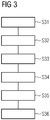
- Figure 3 summarizes some of the steps carried out by the system shown in Figures 1 and 2 in order to generate the tilted tomographic X-ray image 50 as shown in Figure 2 .
- step S31 the 3D dataset comprising the parallel images 15 is generated or, in case it has been generated before, loaded into the control unit 100, so that post processing steps can be carried out.
- step S32 a point of interest is determined in a synthetic mammogram, e.g. either by a user or by post processing methods of the 3D image dataset.
- step S33 the dataset coordinates of the point of interest in the 3D image data set are calculated. As discussed in connection with Figure 2 , the coordinates in the Cartesian coordinate system x1, y1 and z1 are determined based on the radial distance r and the rotation angle ⁇ .
- step S34 the tilted image plane as shown in Figure 2 is determined which comprises the point of interest.
- step S35 the tomographic X-ray image 50 is generated in the determined tilted image plane and in step S36 the tilted tomographic X-ray image 50 is displayed.
- the advantage is to automatically provide the corresponding tomosynthesis slice with a reduced tissue overlap that matches the 3D synthetic mammogram best to provide a more secure diagnosis and a clearer view of a point of interest.
- This is a navigation tool to proceed from the rotating mammogram to the best matching slice.
Landscapes
- Engineering & Computer Science (AREA)
- Health & Medical Sciences (AREA)
- Physics & Mathematics (AREA)
- Life Sciences & Earth Sciences (AREA)
- General Physics & Mathematics (AREA)
- Theoretical Computer Science (AREA)
- Medical Informatics (AREA)
- Computer Graphics (AREA)
- Molecular Biology (AREA)
- General Health & Medical Sciences (AREA)
- Veterinary Medicine (AREA)
- Public Health (AREA)
- Biophysics (AREA)
- High Energy & Nuclear Physics (AREA)
- Animal Behavior & Ethology (AREA)
- Nuclear Medicine, Radiotherapy & Molecular Imaging (AREA)
- Optics & Photonics (AREA)
- Pathology (AREA)
- Radiology & Medical Imaging (AREA)
- Biomedical Technology (AREA)
- Heart & Thoracic Surgery (AREA)
- Surgery (AREA)
- Architecture (AREA)
- Computer Hardware Design (AREA)
- General Engineering & Computer Science (AREA)
- Software Systems (AREA)
- Computer Vision & Pattern Recognition (AREA)
- Dentistry (AREA)
- Oral & Maxillofacial Surgery (AREA)
- Apparatus For Radiation Diagnosis (AREA)
Abstract
Description
- The present invention relates to a method for generating a tilted tomographic X-ray image of an examination object and to the corresponding tomosynthesis apparatus. Furthermore, a computer program comprising programme code is provided.
- Digital Beast Tomosynthesis, DBT, is a new 3D method for X-ray breast imaging. It can be expected that DBT will replace digital mammography in the future. However, due to its 3D character and the reconstruction of many slices through the breast, the amount of image data to be read by the radiologist has increased tremendously compared to 2D mammography. By way of example, the 2D mammography usually comprises two X-ray images of the breasts, which have to be inspected, namely a cranial caudal, CC, projection and the mediolateral oblique, MLO, projection. Digital breast tomosynthesis however usually provides several slices having a thickness of approximately 1 mm through the examined object. For a 50 mm thick compressed breast this amounts to 50 slice images for one view and 100 slice images for two views, namely CC and MLO. Accordingly, the reading of the image data of a DBT examination takes approximately twice the time compared to the known 2D mammography reading.
- In the current system the reading radiologist looks in a stack mode at all slices perhaps in conjunction with the 2D images if available or with a synthetic mammogram, i.e. a 2D mammographic image computed from the tomosynthesis data. If the 3D location of a lesion in the 2D mammogram is known or estimated then the reader can navigate to the slice that contains the lesion. This however is time consuming.
- Accordingly, a need exists to provide the possibility to improve the reading speed for images generated by a tomosynthesis apparatus and to provide an improved possibility to generate views which contain a point of interest such as a lesion.
- This need is met for the features of the independent claims. Further aspects are described in the dependent claims.
- According to a first aspect a method for generating a tilted tomographic X-ray image of an examination object is provided wherein a 3D image data set is provided comprising a plurality of projection X-ray images generated by a tomosynthesis apparatus by moving an X-ray tube of the tomosynthesis apparatus along a path around a rotation axis relative to the examination object and wherein the examination object is irradiated with X-ray at different protection angles of the X-ray tube within a defined projection angle range. Furthermore, from the set of projection images, eventually based on parallel x-ray images (slices) generated from the measured projection images with methods of image reconstruction theory, similar to algorithms known from CT images, (the 3D dataset, synthetic mammograms can be computed, for example a synthetic mammogram parallel to the patient examination table and a set of synthetic rotating mammograms at varying angles with respect to the axis of rotation. Furthermore, a point of interest is determined in one of the synthetic mammograms. Additionally, coordinates of the point of interest in this synthetic mammogram (or in the 3D image data set) are calculated and a tilted image plane (tomographic slice image) is determined or reconstructed through the examination object, wherein the tilted image plane comprises the point of interest and the rotation axis. Furthermore, a tilted tomographic X-ray image in the titled image plane is displayed.
- With the above described method it is possible to automatically provide a corresponding tomographic X-ray image or slice that has a reduced tissue overlap and that includes the point of interest so that a better diagnosis can be made as a better view of the point of interest is obtained. By calculating the tilted slice including the point of interest the reading of the generated X-ray images can be accelerated as the reading radiologist does not have to look in a stacked mode to all of the parallel slices which are available in the 3-D image dataset. The synthetic mammograms are a set of 2 D projection images which can correspond to different projection angles of the X-ray tube but the projection angle must not necessarily be a projection angle where an X-ray image was generated. It can be any projection angle within the defined projection angel range.
- Furthermore, the corresponding tomosynthesis apparatus is provided configured to generate the tilted tomographic X-ray image of the examination object as mentioned above wherein the apparatus comprises an imaging module including an X-ray tube which is configured to move the X-ray tube along a path relative to the examination object around a rotation axis and to irradiate the examination object with X-ray at different projection angles in order to generate the 3D image dataset comprising the measured projection X-ray images and the plurality of computed/reconstructed parallel X-ray (tomographic slice images). An image processing module of the tomosynthesis apparatus is configured to generate and display the tilted tomographic X-ray image as mentioned above.
- The point of interest may be defined by a radial distance r of the point of interest from the rotation axis and by a rotation angle φ. The dataset coordinates are then determined in a Cartesian coordinate system using the radial distance r and the rotation angle φ. The plurality of parallel X-ray images are projection images, which represent the 3D image dataset and in these projection images the point of interest such as a lesion, a mass or calcification is characterized by a radial coordinate and the angle φ.
- Furthermore, it is possible that the point of interest is automatically marked in the synthetic mammogram or the generated tomographic tilted X-ray image. The point of interest can then be easily identified in the synthetic or tomographic tilted X-ray image.
- Furthermore, it is possible that a vertical height of the point of interest is determined in a direction perpendicular to the plurality of parallel X-ray images. Furthermore, a first parallel image is determined in the 3D image dataset that is provided in the 3D image dataset at the determined vertical height and the first parallel image that is located at the determined vertical height is displayed in addition to the tilted synthetic or tomographic X-ray image.
- Furthermore, it is possible to determine at least a first neighboring tomographic image which is located parallel to the tilted tomographic X-ray image in an image plane adjacent and parallel to the tilted image plane. By generating neighboring tomographic images having the same tilt angle as the tilted tomographic X-ray image, slices in the direct neighborhood of the point of interest can be examined in order to assess whether the determined point of interest is a benign or malign structure.
- Furthermore, it is possible to determine at least one second neighboring tomographic image passing through the rotation axis at an angle located between φ + Δφ and φ - Δφ, wherein Δφ is much smaller than the rotation angle and is smaller than one 10th of the rotation angle φ itself. By generating the further image with a slight different rotation angle the neighborhood of the point of interest can be examined in more detail.
- In the 3D dataset each of the plurality of rotated/tilted X-ray images can correspond to a different real or virtual projection angle of the X-ray tube and the origin of the Cartesian coordinate system can be located on the rotation axis. The projection angle can correspond to any projection angle within the possible projection angle range.
- Furthermore, a computer program comprising program code to be executed by at least one image processing module of a tomosynthesis apparatus is provided where an execution of the program code causes the at least one image processing module to execute a method as discussed above or as discussed in further detail below.
- It is to be understood the features mentioned above and features yet to be explained below can be used not only in the respective combinations indicated, but also in other combinations or in isolation without departing from the scope of the present invention. Features of the above-mentioned aspects and embodiments described below may be combined with each other in other embodiments unless explicitly mentioned otherwise.
- The foregoing and additional features and effects of the invention will become apparent from the following detailed description when read in conjunction with the accompanying drawings in which like reference numerals refer to like elements.
- Figure 1
- shows a schematic architectural view of a tomosynthesis apparatus configured to determine a tilted tomographic X-ray image including a point of interest.
- Figure 2
- is a schematic overview of the different coordinate systems involved and how the tilted tomographic X-ray image is located in a 3D dataset.
- Figure 3
- shows an example flowchart of a method carried out by a tomosynthesis apparatus for generating and displaying the tilted tomographic X-ray image.
- In the following, embodiments of the invention will be described in detail with reference to the accompanying drawings. It is to be understood that the following description of embodiments is not to be taken in a limiting sense. The scope of the invention is not intended to be limited by the embodiments described hereinafter or by the drawings, which are to be illustrative only.
- The drawings are to be regarded as being schematic representations, and elements illustrated in the drawings are not necessarily shown to scale. Rather, the various elements are represented such that their function and general-purpose becomes apparent to a person skilled in the art. Any connection or coupling between functional blocks, devices, components of physical or functional units shown in the drawings and described hereinafter may also be implemented by an indirect connection or coupling. A coupling between components may be established over a wired or wireless connection. Functional blocks may be implemented in hardware, software, firmware, or a combination thereof.
- As shown in
Figure 1 the tomosynthesis apparatus comprises anX-ray tube 2 for generating an X-ray beam 3 that passes through anexamination object 4 which is held between acompression plate 6 and a patient examination table 8. In the example shown the examined object may be a breast which is held between theplate 6 and the table 8. However, the imaging discussed below is not only applicable to breast tomosynthesis, but to any other examination object such as the lung or different bones. - As the
X-ray tube 2 is moved through a number of protection angles, X-ray beams pass through the examinedobject 4 and are received by anX-ray detector 10 which can be composed of a number ofindividual detectors 12 arranged in a matrix like array. TheX-ray tube 2 can be rotated from a starting position at k-0 through various angle positions up to a maximum projection angle αmax so that individual projection X-ray images are obtained at different projection angles α relative to a normal 13 of the patient examination table 8 of theX-ray detector 10. TheX-ray tube 2 and thedetector 10 are connected to acontrol module 100 of the tomosynthesis apparatus. Thecontrol module 100 can comprise different modules needed for controlling the movement of the X-ray tube and for reading the generated data from thedetector 10. For the sake of clarity, these different modules are not shown. Only the modules needed for the understanding of the invention are disclosed. - The
control module 100 comprises animage processing module 110 which will be able to generate a tilted tomographic X-ray image as will be discussed below. Amemory 120 is provided where the generated X-ray images can be stored and where computer programs needed for the operation of the tomosynthesis apparatus may be stored. Adisplay module 130 is provided for displaying the generated images and aninput unit 140 may be used by a user of the tomosynthesis apparatus to control the operation of the apparatus. - In the tomosynthesis it is not possible to reconstruct an isotropic 3D volume data set since the examined object is sampled only within a limited view angle as shown in
Figure 1 that is typically between 15 and 60°. Accordingly, onlyX-ray images 15 parallel to the examination table 8 and parallel to the detector 10 (if stationary) are generated. However, it is possible to reconstruct tomographic slice images, the tilted tomographic X ray image called hereinafter, tilted with respect to the standard plane as defined by theX-ray images 15 if the angle is within the tomosynthesis angular range. - Furthermore, it is possible to synthesize images from the 3D image data set such as a 3D synthetic mammogram or a rotating mammogram, which is a set of 2D synthetic mammograms, images computed from the tomosynthesis data set including the projection data detected at
detector 10 and tomographic slice images 15). In this set of synthetic mammograms, each image may correspond to a different viewing angle of theX-ray tube 2 that scans the examination object. - The situation is shown in further detail in
Figure 2 , which shows the coordinate system which is defined by the vertical direction z through the examination object and perpendicular to thestationary detector 10 and table 8 and the parallel normal 13. The X-ray tube is moved in the y direction as shown inFigure 2 and the x direction is perpendicular to y and z as shown inFigure 2 . The origin of the coordinate system may be the intersection of the plane that is perpendicular to the table 8 and parallel to a chest wall side of the table 8 and the rotation axis of the tube or any other line through the center of the table 8 perpendicular to the chest wall. - The system has generated the 3D synthetic dataset comprising the plurality of synthetic mammograms and in this 3D synthetic image dataset a point of
interest 30 is identified. This point ofinterest 30 can be a lesion, a calcification or any other object. This point of interest is characterized by the radial coordinate r and the angle φ in the y, z plane and is characterized by the coordinate x. Theimage processing module 110 can then calculate the coordinates x1, y1 and z1 of this point in the 3D data volume using the following equations:
- The
image processing module 110 can then reconstruct a tomographic slice, the tilted tomographic X-ray image such asslice 50 which is tilted versus the x,y plane and which contains the determined point ofinterest 30 and contains the middle axis, here the x direction through the patient support perpendicular to the left right or y direction. In the present case the x axis also represents the rotation axis. This slice can then be displayed together with the synthetic mammogram at the specific angle. - It is possible that the point of interest is automatically marked in the synthetic mammogram and in the reconstructed tilted tomographic
graphic X-ray image 50 for a navigation and registration purpose. - Alternatively, it is possible that the marking generated in the synthetic mammogram and/or the tilted
tomographic X-ray image 50 is a mark that is computed by a computer assisted diagnosis, CAD, system. Furthermore, it is possible to determine aslice 60 in the 3D image data set which is parallel to theother images 15 and which also contains the point ofinterest 30. Thisslice 60 is parallel to the support table 8 and is located at the determined set coordinate z1. Furthermore, it is possible to determine other slices parallel to the tiltedtomographic slice 50 in a neighboring slice either above or below the slice so that the direct surrounding off the point of interest is also displayed in a tilted image. Furthermore, it is possible to change the tilting angle φ by a slight amount to generate further images passing through the rotation axis but with a slightly larger tilting angle or a slightly lower tilting angle so that the director surrounding of the point of interest is also shown in these images. -
Figure 3 summarizes some of the steps carried out by the system shown inFigures 1 and2 in order to generate the tiltedtomographic X-ray image 50 as shown inFigure 2 . - In step S31 the 3D dataset comprising the
parallel images 15 is generated or, in case it has been generated before, loaded into thecontrol unit 100, so that post processing steps can be carried out. - In step S32 a point of interest is determined in a synthetic mammogram, e.g. either by a user or by post processing methods of the 3D image dataset. In step S33 the dataset coordinates of the point of interest in the 3D image data set are calculated. As discussed in connection with
Figure 2 , the coordinates in the Cartesian coordinate system x1, y1 and z1 are determined based on the radial distance r and the rotation angle φ. In step S34 the tilted image plane as shown inFigure 2 is determined which comprises the point of interest. In step S35 thetomographic X-ray image 50 is generated in the determined tilted image plane and in step S36 the tiltedtomographic X-ray image 50 is displayed. - In the claimed invention, the advantage is to automatically provide the corresponding tomosynthesis slice with a reduced tissue overlap that matches the 3D synthetic mammogram best to provide a more secure diagnosis and a clearer view of a point of interest. This is a navigation tool to proceed from the rotating mammogram to the best matching slice.
Claims (14)
- A method for generating a tilted tomographic X-ray image (50) of an examination object (4), the method comprising:- providing a 3D image data set comprising a plurality of projection X-ray images generated by a tomosynthesis apparatus by moving an X-ray tube (2) of the tomosynthesis apparatus along a path around a rotation axis relative to the examination object and irradiating the examination object with X-ray at different projection angles within a defined projection angle range,- determining, based on the 3D image data set, synthetic mammograms corresponding to different angles within the defined projection angle range,- determining a point of interest (30) in one of the synthetic mammograms,- calculating coordinates of the point of interest in said one synthetic mammogram or the 3D dataset,- determining a tilted image plane through the examination object, the tilted image plane comprising the point of interest (30) and the rotation axis,- generating the tilted tomographic X-ray image (50) in the tilted image plane based on the provided 3D image data set, and- displaying the tilted tomographic X-ray image (50).
- The method according to claim 1 wherein the point of interest (30) is defined by a radial distance r of the point of interest from the rotation axis and a rotation angle φ and wherein the data set coordinates are determined in a Cartesian coordinate system (x,y,z) using the radial distance r and the rotation angle φ.
- The method according to claim 1 or 2, wherein the point of interest (30) is automatically marked in said one synthetic mammogram.
- The method according to claim 1 or 2, wherein the point of interest (30) is automatically marked in the generated tilted tomographic X-ray image (50) .
- The method according to any of the preceding claims, further comprising:- determining a vertical height of the point of interest (30) in a direction perpendicular to the plurality of parallel X-ray images (15),- determining in the 3D image data set a first parallel image (60) in the plurality of parallel X-ray images that is provided in the 3D image data set at the determined vertical height, and- displaying the first parallel image (60) in addition to the tilted tomographic X-ray image.
- The method according to any of the preceding claims, further determining at least a first neighboring tomographic image which is located parallel to the tilted tomographic X-ray image in an image plane adjacent and parallel to the tiled image plane.
- The method according to any of claims 2 to 6, further determining at least one second neighboring tomographic image passing through the rotation axis at an angle located between φ + Δφ and φ - Δφ, with Δφ being smaller than 10% of the rotation angle φ.
- A tomosynthesis apparatus configured to generate a tilted tomographic X-ray image of an examination object, the apparatus comprising:- an imaging module including an X-ray tube (2) configured to move the X-ray tube along a path relative to the examination object and to irradiate the examination object (4) with X-ray at different projection angles within a defined projection angle range around a rotation axis and to generate a 3D image data set comprising a plurality of projection X-ray images generated at the different projection angles,- an image processing module (110) configured to- determine, based on the 3D image data set, synthetic mammograms corresponding to different projection angles within the defined projection angle range,- determine a point of interest in one of the synthetic mammograms,- calculate coordinates of the point of interest (30) in said one synthetic mammogram or the 3 D dataset,- determine a tilted image plane through the examination object (4), the tilted image plane comprising the point of interest (30) and the rotation axis,- generate the tilted tomographic X-ray image (50) in the tilted image plane based on the provided 3D image data set, and- display the tilted tomographic X-ray image (50).
- The tomosynthesis apparatus according to claim 8, wherein the image processing module (110) is configured to determine the data set coordinates in a Cartesian coordinate system based on a radial distance r of the point of interest (30) from the rotation axis and a rotation angle φ around the rotation axis.
- The tomosynthesis apparatus according to claim 8 or 9, wherein the image processing module (110) is configured to automatically mark the point of interest (30) in at least one of the tilted tomographic X-ray image (50) and said one synthetic mammogram.
- The tomosynthesis apparatus according to any of claims 8 to 10, wherein the image processing module (110) is configured to- determine a vertical height of the point of interest (30) in a direction perpendicular to the plurality of parallel X-ray images,- determine in the 3D image (60) data set a first parallel image (60) in the plurality of parallel X-ray images that is provided in the 3D image data set at the determined vertical height, and- display the first parallel image in addition to the generated tomographic X-ray image.
- The tomosynthesis apparatus according to any of claims 8 to 11, wherein the image processing module (110) is configured to determine at least a first neighboring tomographic image which is located parallel to the tilted generated tomographic X-ray image in an image plane adjacent and parallel to the tiled image plane.
- The tomosysthesis apparatus according to any of claims 9 to 12, wherein the image processing module (110) is configured to determine at least one second neighboring tomographic image passing through the rotation axis at an angle located between φ + Δφ and φ - Δφ, with Δφ being smaller than 10% of the rotation angle φ.
- A computer program comprising program code to be executed by at least one image processing module (110) of an tomosynthesis apparatus, wherein execution of the program code causes the at least one image processing module to execute a method according to any of claims 1 to 7.
Priority Applications (2)
| Application Number | Priority Date | Filing Date | Title |
|---|---|---|---|
| EP18153688.9A EP3518182B1 (en) | 2018-01-26 | 2018-01-26 | Tilted slices in dbt |
| US16/251,210 US10973487B2 (en) | 2018-01-26 | 2019-01-18 | Tilted slices in DBT |
Applications Claiming Priority (1)
| Application Number | Priority Date | Filing Date | Title |
|---|---|---|---|
| EP18153688.9A EP3518182B1 (en) | 2018-01-26 | 2018-01-26 | Tilted slices in dbt |
Publications (2)
| Publication Number | Publication Date |
|---|---|
| EP3518182A1 true EP3518182A1 (en) | 2019-07-31 |
| EP3518182B1 EP3518182B1 (en) | 2022-05-18 |
Family
ID=61094231
Family Applications (1)
| Application Number | Title | Priority Date | Filing Date |
|---|---|---|---|
| EP18153688.9A Active EP3518182B1 (en) | 2018-01-26 | 2018-01-26 | Tilted slices in dbt |
Country Status (2)
| Country | Link |
|---|---|
| US (1) | US10973487B2 (en) |
| EP (1) | EP3518182B1 (en) |
Cited By (2)
| Publication number | Priority date | Publication date | Assignee | Title |
|---|---|---|---|---|
| CN111654685A (en) * | 2020-08-06 | 2020-09-11 | 成都极米科技股份有限公司 | Moving direction detection method and device, projection equipment and readable storage medium |
| WO2023072266A1 (en) * | 2021-10-29 | 2023-05-04 | Shanghai United Imaging Healthcare Co., Ltd. | Methods, systems and computer storage mediums for image processing |
Families Citing this family (2)
| Publication number | Priority date | Publication date | Assignee | Title |
|---|---|---|---|---|
| DE102020209706A1 (en) | 2020-07-31 | 2022-02-03 | Siemens Healthcare Gmbh | Synthetic mammogram with reduced overlay of tissue changes |
| CN121420189A (en) * | 2023-06-01 | 2026-01-27 | 拉皮斯坎控股公司 | Systems and methods for automatically generating synthetic X-ray scan data of objects in multiple orientations |
Citations (6)
| Publication number | Priority date | Publication date | Assignee | Title |
|---|---|---|---|---|
| US4769756A (en) * | 1986-08-07 | 1988-09-06 | The United States Of America As Represented By The Department Of Health And Human Services | Systematic method for matching existing radiographic projections with radiographs to be produced from a specified region of interest in cancellous bone |
| US20060002601A1 (en) * | 2004-06-30 | 2006-01-05 | Accuray, Inc. | DRR generation using a non-linear attenuation model |
| WO2014110283A1 (en) * | 2013-01-10 | 2014-07-17 | Hologic, Inc. | System and method for reducing data transmission volume in tomosynthesis |
| WO2014207080A1 (en) * | 2013-06-28 | 2014-12-31 | Koninklijke Philips N.V. | Methods for generation of edge-preserving synthetic mammograms from tomosynthesis data |
| WO2016078958A1 (en) * | 2014-11-20 | 2016-05-26 | Koninklijke Philips N.V. | Method for generation of synthetic mammograms from tomosynthesis data |
| US20170365076A1 (en) * | 2016-06-21 | 2017-12-21 | Carestream Health, Inc. | Virtual projection image method |
Family Cites Families (33)
| Publication number | Priority date | Publication date | Assignee | Title |
|---|---|---|---|---|
| US6480565B1 (en) * | 1999-11-18 | 2002-11-12 | University Of Rochester | Apparatus and method for cone beam volume computed tomography breast imaging |
| US6671349B1 (en) * | 2000-11-13 | 2003-12-30 | Olganix Corporation | Tomosynthesis system and registration method |
| EP1424939A4 (en) * | 2001-03-30 | 2005-05-18 | Univ Duke | TOMOGRAPHY BY EMISSION AND SPECIFIC OPACITY OF THE APPLICATION |
| US6796085B2 (en) * | 2003-01-24 | 2004-09-28 | Peter J. Smith | Window regulator |
| JP4709604B2 (en) * | 2004-08-03 | 2011-06-22 | 株式会社東芝 | Image display device, image display method, storage medium, and program |
| US10008184B2 (en) * | 2005-11-10 | 2018-06-26 | Hologic, Inc. | System and method for generating a 2D image using mammography and/or tomosynthesis image data |
| FR2902218A1 (en) * | 2006-06-07 | 2007-12-14 | Gen Electric | METHOD FOR PROCESSING TOMOSYNTHESIS IMAGES FOR DETECTION OF RADIOLOGICAL SIGNS |
| US8233690B2 (en) * | 2008-04-30 | 2012-07-31 | Real-Time Tomography, Llc | Dynamic tomographic image reconstruction and rendering on-demand |
| DE102008028387B4 (en) * | 2008-06-13 | 2018-05-17 | Siemens Healthcare Gmbh | A tomographic image reconstruction method for generating an image of an examination object and an imaging device operating according to this method |
| DE102008050571A1 (en) * | 2008-10-06 | 2010-04-15 | Siemens Aktiengesellschaft | Tomosynthesis apparatus and method for operating a tomosynthesis apparatus |
| US8223916B2 (en) * | 2009-03-31 | 2012-07-17 | Hologic, Inc. | Computer-aided detection of anatomical abnormalities in x-ray tomosynthesis images |
| US20120224664A1 (en) * | 2009-11-20 | 2012-09-06 | Koninklijke Philips Electronics N.V. | Tomosynthesis mammography system with enlarged field of view |
| DE102010063810B4 (en) * | 2010-12-21 | 2019-06-06 | Siemens Healthcare Gmbh | An imaging method and apparatus for displaying decompressed views of a tissue area |
| WO2012106204A1 (en) * | 2011-01-31 | 2012-08-09 | University Of Massachusetts | Tomosynthesis imaging |
| DE102011006058A1 (en) * | 2011-03-24 | 2012-09-27 | Siemens Aktiengesellschaft | Tomosynthesis device and method for its operation |
| DE102011006353A1 (en) * | 2011-03-29 | 2012-10-04 | Siemens Aktiengesellschaft | mammography system |
| DE102011076929A1 (en) * | 2011-06-03 | 2012-12-06 | Siemens Ag | Method and apparatus for displaying volume data for a study of density properties |
| DE102011076930A1 (en) * | 2011-06-03 | 2012-12-06 | Siemens Aktiengesellschaft | Method and device for adapting the representation of volume data of an object |
| DE102011087337B4 (en) * | 2011-11-29 | 2016-10-13 | Siemens Healthcare Gmbh | A method of reconstructing a reconstruction data set containing two-dimensional virtual X-ray images |
| WO2013123091A1 (en) * | 2012-02-13 | 2013-08-22 | Hologic, Inc. | System and method for navigating a tomosynthesis stack using synthesized image data |
| WO2013136222A2 (en) * | 2012-03-12 | 2013-09-19 | Koninklijke Philips N.V. | Providing image information of an object |
| US10593069B2 (en) * | 2013-03-15 | 2020-03-17 | Real Time Tomography, Llc | Enhancements for displaying and viewing Tomosynthesis images |
| US20140343344A1 (en) * | 2013-04-08 | 2014-11-20 | Cubresa Inc. | Radiation Therapy Guided Using Gamma Imaging |
| EP3005298B1 (en) * | 2013-06-06 | 2019-04-17 | Volpara Health Technologies Limited | A method of reconstruction of an object from projection views |
| DE102013215376B4 (en) * | 2013-08-05 | 2023-03-23 | Siemens Healthcare Gmbh | Mammography device and method for operating a mammography device |
| WO2015063188A1 (en) * | 2013-10-30 | 2015-05-07 | Koninklijke Philips N.V. | Method and device for displaying medical images |
| DE102014213464A1 (en) * | 2014-07-10 | 2016-01-14 | Siemens Aktiengesellschaft | Method for combined dual-energy mammography and tomosynthesis imaging and tomosynthesis apparatus |
| DE102014213412A1 (en) * | 2014-07-10 | 2016-01-14 | Siemens Aktiengesellschaft | Multi-mode X-ray machine |
| US9836858B2 (en) * | 2014-09-19 | 2017-12-05 | Siemens Aktiengesellschaft | Method for generating a combined projection image and imaging device |
| JP2016131573A (en) * | 2015-01-15 | 2016-07-25 | キヤノン株式会社 | Control device of tomosynthesis imaging, radiographic device, control system, control method, and program |
| US20160256713A1 (en) * | 2015-02-11 | 2016-09-08 | Cubresa Inc. | Radiation Therapy Guided Using PET Imaging |
| WO2016142492A1 (en) * | 2015-03-10 | 2016-09-15 | Koninklijke Philips N.V. | Retrieval of corresponding structures in pairs of medical images |
| DE102016204828B4 (en) * | 2016-03-23 | 2022-09-15 | Siemens Healthcare Gmbh | Generation of a combined contrast agent and vessel display of breast tissue to be examined |
-
2018
- 2018-01-26 EP EP18153688.9A patent/EP3518182B1/en active Active
-
2019
- 2019-01-18 US US16/251,210 patent/US10973487B2/en active Active
Patent Citations (6)
| Publication number | Priority date | Publication date | Assignee | Title |
|---|---|---|---|---|
| US4769756A (en) * | 1986-08-07 | 1988-09-06 | The United States Of America As Represented By The Department Of Health And Human Services | Systematic method for matching existing radiographic projections with radiographs to be produced from a specified region of interest in cancellous bone |
| US20060002601A1 (en) * | 2004-06-30 | 2006-01-05 | Accuray, Inc. | DRR generation using a non-linear attenuation model |
| WO2014110283A1 (en) * | 2013-01-10 | 2014-07-17 | Hologic, Inc. | System and method for reducing data transmission volume in tomosynthesis |
| WO2014207080A1 (en) * | 2013-06-28 | 2014-12-31 | Koninklijke Philips N.V. | Methods for generation of edge-preserving synthetic mammograms from tomosynthesis data |
| WO2016078958A1 (en) * | 2014-11-20 | 2016-05-26 | Koninklijke Philips N.V. | Method for generation of synthetic mammograms from tomosynthesis data |
| US20170365076A1 (en) * | 2016-06-21 | 2017-12-21 | Carestream Health, Inc. | Virtual projection image method |
Cited By (2)
| Publication number | Priority date | Publication date | Assignee | Title |
|---|---|---|---|---|
| CN111654685A (en) * | 2020-08-06 | 2020-09-11 | 成都极米科技股份有限公司 | Moving direction detection method and device, projection equipment and readable storage medium |
| WO2023072266A1 (en) * | 2021-10-29 | 2023-05-04 | Shanghai United Imaging Healthcare Co., Ltd. | Methods, systems and computer storage mediums for image processing |
Also Published As
| Publication number | Publication date |
|---|---|
| US20190231292A1 (en) | 2019-08-01 |
| EP3518182B1 (en) | 2022-05-18 |
| US10973487B2 (en) | 2021-04-13 |
Similar Documents
| Publication | Publication Date | Title |
|---|---|---|
| US11246551B2 (en) | System and method for computer aided detection (CAD) in a breast specimen radiograph | |
| RU2686953C2 (en) | Method and apparatus for displaying medical images | |
| US10733792B2 (en) | Method and apparatus for user guidance for the choice of a two-dimensional angiographic projection | |
| US9138193B2 (en) | Specimen radiography with tomosynthesis in a cabinet | |
| US9782134B2 (en) | Lesion imaging optimization using a tomosynthesis/biopsy system | |
| EP2428163B1 (en) | Methods and systems for dynamically modifying acquisition parameter during image acquisition | |
| US10235796B2 (en) | Method and apparatus for selection of perspective orientation of a two dimensional angiographic image | |
| CN104939850B (en) | Imaging fault synthesis system, particularly mammary gland angiography system | |
| US20250134477A1 (en) | Orientation system for specimen imaging apparatus | |
| US9865067B2 (en) | Method of reconstruction of an object from projection views | |
| US20120033868A1 (en) | Detecting and quantifying patient motion during tomosynthesis scans | |
| JP7275363B2 (en) | Positional deviation amount derivation device, method and program | |
| US10672517B2 (en) | Method and device for monitoring a breast examination | |
| EP3518182B1 (en) | Tilted slices in dbt | |
| US10368822B2 (en) | Iterative X-ray imaging optimization method and system | |
| US11013473B2 (en) | Method and image reconstruction device for visualizing a region of interest, tomosynthesis system and computer program product | |
| US10751007B2 (en) | Generating an image sequence | |
| EP3648063B1 (en) | Image display apparatus, radiation imaging display system, image display method, and image display program | |
| US6760469B1 (en) | Flipping stereoscopic radiographs | |
| US10115485B2 (en) | Method of planning an examination, method of positioning an examination instrument, tomosynthesis system and computer program product | |
| US11259783B2 (en) | Determining a region of interest to be rendered | |
| Das et al. | Evaluation of a variable dose acquisition methodology for breast tomosynthesis | |
| US20250255565A1 (en) | Specimen radiography with tomosynthesis in a cabinet plus |
Legal Events
| Date | Code | Title | Description |
|---|---|---|---|
| PUAI | Public reference made under article 153(3) epc to a published international application that has entered the european phase |
Free format text: ORIGINAL CODE: 0009012 |
|
| STAA | Information on the status of an ep patent application or granted ep patent |
Free format text: STATUS: THE APPLICATION HAS BEEN PUBLISHED |
|
| AK | Designated contracting states |
Kind code of ref document: A1 Designated state(s): AL AT BE BG CH CY CZ DE DK EE ES FI FR GB GR HR HU IE IS IT LI LT LU LV MC MK MT NL NO PL PT RO RS SE SI SK SM TR |
|
| AX | Request for extension of the european patent |
Extension state: BA ME |
|
| STAA | Information on the status of an ep patent application or granted ep patent |
Free format text: STATUS: REQUEST FOR EXAMINATION WAS MADE |
|
| 17P | Request for examination filed |
Effective date: 20191205 |
|
| RBV | Designated contracting states (corrected) |
Designated state(s): AL AT BE BG CH CY CZ DE DK EE ES FI FR GB GR HR HU IE IS IT LI LT LU LV MC MK MT NL NO PL PT RO RS SE SI SK SM TR |
|
| STAA | Information on the status of an ep patent application or granted ep patent |
Free format text: STATUS: EXAMINATION IS IN PROGRESS |
|
| 17Q | First examination report despatched |
Effective date: 20210420 |
|
| GRAP | Despatch of communication of intention to grant a patent |
Free format text: ORIGINAL CODE: EPIDOSNIGR1 |
|
| STAA | Information on the status of an ep patent application or granted ep patent |
Free format text: STATUS: GRANT OF PATENT IS INTENDED |
|
| INTG | Intention to grant announced |
Effective date: 20211007 |
|
| GRAJ | Information related to disapproval of communication of intention to grant by the applicant or resumption of examination proceedings by the epo deleted |
Free format text: ORIGINAL CODE: EPIDOSDIGR1 |
|
| STAA | Information on the status of an ep patent application or granted ep patent |
Free format text: STATUS: EXAMINATION IS IN PROGRESS |
|
| INTC | Intention to grant announced (deleted) | ||
| GRAP | Despatch of communication of intention to grant a patent |
Free format text: ORIGINAL CODE: EPIDOSNIGR1 |
|
| STAA | Information on the status of an ep patent application or granted ep patent |
Free format text: STATUS: GRANT OF PATENT IS INTENDED |
|
| INTG | Intention to grant announced |
Effective date: 20220127 |
|
| GRAS | Grant fee paid |
Free format text: ORIGINAL CODE: EPIDOSNIGR3 |
|
| GRAA | (expected) grant |
Free format text: ORIGINAL CODE: 0009210 |
|
| STAA | Information on the status of an ep patent application or granted ep patent |
Free format text: STATUS: THE PATENT HAS BEEN GRANTED |
|
| AK | Designated contracting states |
Kind code of ref document: B1 Designated state(s): AL AT BE BG CH CY CZ DE DK EE ES FI FR GB GR HR HU IE IS IT LI LT LU LV MC MK MT NL NO PL PT RO RS SE SI SK SM TR |
|
| REG | Reference to a national code |
Ref country code: GB Ref legal event code: FG4D |
|
| REG | Reference to a national code |
Ref country code: CH Ref legal event code: EP |
|
| REG | Reference to a national code |
Ref country code: IE Ref legal event code: FG4D |
|
| REG | Reference to a national code |
Ref country code: DE Ref legal event code: R096 Ref document number: 602018035661 Country of ref document: DE |
|
| REG | Reference to a national code |
Ref country code: AT Ref legal event code: REF Ref document number: 1493594 Country of ref document: AT Kind code of ref document: T Effective date: 20220615 |
|
| REG | Reference to a national code |
Ref country code: LT Ref legal event code: MG9D |
|
| REG | Reference to a national code |
Ref country code: NL Ref legal event code: MP Effective date: 20220518 |
|
| REG | Reference to a national code |
Ref country code: AT Ref legal event code: MK05 Ref document number: 1493594 Country of ref document: AT Kind code of ref document: T Effective date: 20220518 |
|
| PG25 | Lapsed in a contracting state [announced via postgrant information from national office to epo] |
Ref country code: SE Free format text: LAPSE BECAUSE OF FAILURE TO SUBMIT A TRANSLATION OF THE DESCRIPTION OR TO PAY THE FEE WITHIN THE PRESCRIBED TIME-LIMIT Effective date: 20220518 Ref country code: PT Free format text: LAPSE BECAUSE OF FAILURE TO SUBMIT A TRANSLATION OF THE DESCRIPTION OR TO PAY THE FEE WITHIN THE PRESCRIBED TIME-LIMIT Effective date: 20220919 Ref country code: NO Free format text: LAPSE BECAUSE OF FAILURE TO SUBMIT A TRANSLATION OF THE DESCRIPTION OR TO PAY THE FEE WITHIN THE PRESCRIBED TIME-LIMIT Effective date: 20220818 Ref country code: NL Free format text: LAPSE BECAUSE OF FAILURE TO SUBMIT A TRANSLATION OF THE DESCRIPTION OR TO PAY THE FEE WITHIN THE PRESCRIBED TIME-LIMIT Effective date: 20220518 Ref country code: LT Free format text: LAPSE BECAUSE OF FAILURE TO SUBMIT A TRANSLATION OF THE DESCRIPTION OR TO PAY THE FEE WITHIN THE PRESCRIBED TIME-LIMIT Effective date: 20220518 Ref country code: HR Free format text: LAPSE BECAUSE OF FAILURE TO SUBMIT A TRANSLATION OF THE DESCRIPTION OR TO PAY THE FEE WITHIN THE PRESCRIBED TIME-LIMIT Effective date: 20220518 Ref country code: GR Free format text: LAPSE BECAUSE OF FAILURE TO SUBMIT A TRANSLATION OF THE DESCRIPTION OR TO PAY THE FEE WITHIN THE PRESCRIBED TIME-LIMIT Effective date: 20220819 Ref country code: FI Free format text: LAPSE BECAUSE OF FAILURE TO SUBMIT A TRANSLATION OF THE DESCRIPTION OR TO PAY THE FEE WITHIN THE PRESCRIBED TIME-LIMIT Effective date: 20220518 Ref country code: ES Free format text: LAPSE BECAUSE OF FAILURE TO SUBMIT A TRANSLATION OF THE DESCRIPTION OR TO PAY THE FEE WITHIN THE PRESCRIBED TIME-LIMIT Effective date: 20220518 Ref country code: BG Free format text: LAPSE BECAUSE OF FAILURE TO SUBMIT A TRANSLATION OF THE DESCRIPTION OR TO PAY THE FEE WITHIN THE PRESCRIBED TIME-LIMIT Effective date: 20220818 Ref country code: AT Free format text: LAPSE BECAUSE OF FAILURE TO SUBMIT A TRANSLATION OF THE DESCRIPTION OR TO PAY THE FEE WITHIN THE PRESCRIBED TIME-LIMIT Effective date: 20220518 |
|
| PG25 | Lapsed in a contracting state [announced via postgrant information from national office to epo] |
Ref country code: RS Free format text: LAPSE BECAUSE OF FAILURE TO SUBMIT A TRANSLATION OF THE DESCRIPTION OR TO PAY THE FEE WITHIN THE PRESCRIBED TIME-LIMIT Effective date: 20220518 Ref country code: PL Free format text: LAPSE BECAUSE OF FAILURE TO SUBMIT A TRANSLATION OF THE DESCRIPTION OR TO PAY THE FEE WITHIN THE PRESCRIBED TIME-LIMIT Effective date: 20220518 Ref country code: LV Free format text: LAPSE BECAUSE OF FAILURE TO SUBMIT A TRANSLATION OF THE DESCRIPTION OR TO PAY THE FEE WITHIN THE PRESCRIBED TIME-LIMIT Effective date: 20220518 Ref country code: IS Free format text: LAPSE BECAUSE OF FAILURE TO SUBMIT A TRANSLATION OF THE DESCRIPTION OR TO PAY THE FEE WITHIN THE PRESCRIBED TIME-LIMIT Effective date: 20220918 |
|
| PG25 | Lapsed in a contracting state [announced via postgrant information from national office to epo] |
Ref country code: SM Free format text: LAPSE BECAUSE OF FAILURE TO SUBMIT A TRANSLATION OF THE DESCRIPTION OR TO PAY THE FEE WITHIN THE PRESCRIBED TIME-LIMIT Effective date: 20220518 Ref country code: SK Free format text: LAPSE BECAUSE OF FAILURE TO SUBMIT A TRANSLATION OF THE DESCRIPTION OR TO PAY THE FEE WITHIN THE PRESCRIBED TIME-LIMIT Effective date: 20220518 Ref country code: RO Free format text: LAPSE BECAUSE OF FAILURE TO SUBMIT A TRANSLATION OF THE DESCRIPTION OR TO PAY THE FEE WITHIN THE PRESCRIBED TIME-LIMIT Effective date: 20220518 Ref country code: EE Free format text: LAPSE BECAUSE OF FAILURE TO SUBMIT A TRANSLATION OF THE DESCRIPTION OR TO PAY THE FEE WITHIN THE PRESCRIBED TIME-LIMIT Effective date: 20220518 Ref country code: DK Free format text: LAPSE BECAUSE OF FAILURE TO SUBMIT A TRANSLATION OF THE DESCRIPTION OR TO PAY THE FEE WITHIN THE PRESCRIBED TIME-LIMIT Effective date: 20220518 Ref country code: CZ Free format text: LAPSE BECAUSE OF FAILURE TO SUBMIT A TRANSLATION OF THE DESCRIPTION OR TO PAY THE FEE WITHIN THE PRESCRIBED TIME-LIMIT Effective date: 20220518 |
|
| REG | Reference to a national code |
Ref country code: DE Ref legal event code: R097 Ref document number: 602018035661 Country of ref document: DE |
|
| PLBE | No opposition filed within time limit |
Free format text: ORIGINAL CODE: 0009261 |
|
| STAA | Information on the status of an ep patent application or granted ep patent |
Free format text: STATUS: NO OPPOSITION FILED WITHIN TIME LIMIT |
|
| PG25 | Lapsed in a contracting state [announced via postgrant information from national office to epo] |
Ref country code: AL Free format text: LAPSE BECAUSE OF FAILURE TO SUBMIT A TRANSLATION OF THE DESCRIPTION OR TO PAY THE FEE WITHIN THE PRESCRIBED TIME-LIMIT Effective date: 20220518 |
|
| 26N | No opposition filed |
Effective date: 20230221 |
|
| PG25 | Lapsed in a contracting state [announced via postgrant information from national office to epo] |
Ref country code: SI Free format text: LAPSE BECAUSE OF FAILURE TO SUBMIT A TRANSLATION OF THE DESCRIPTION OR TO PAY THE FEE WITHIN THE PRESCRIBED TIME-LIMIT Effective date: 20220518 |
|
| PGFP | Annual fee paid to national office [announced via postgrant information from national office to epo] |
Ref country code: DE Payment date: 20220620 Year of fee payment: 6 |
|
| REG | Reference to a national code |
Ref country code: CH Ref legal event code: PL |
|
| GBPC | Gb: european patent ceased through non-payment of renewal fee |
Effective date: 20230126 |
|
| PG25 | Lapsed in a contracting state [announced via postgrant information from national office to epo] |
Ref country code: LU Free format text: LAPSE BECAUSE OF NON-PAYMENT OF DUE FEES Effective date: 20230126 |
|
| REG | Reference to a national code |
Ref country code: BE Ref legal event code: MM Effective date: 20230131 |
|
| PG25 | Lapsed in a contracting state [announced via postgrant information from national office to epo] |
Ref country code: LI Free format text: LAPSE BECAUSE OF NON-PAYMENT OF DUE FEES Effective date: 20230131 Ref country code: GB Free format text: LAPSE BECAUSE OF NON-PAYMENT OF DUE FEES Effective date: 20230126 Ref country code: CH Free format text: LAPSE BECAUSE OF NON-PAYMENT OF DUE FEES Effective date: 20230131 |
|
| PG25 | Lapsed in a contracting state [announced via postgrant information from national office to epo] |
Ref country code: FR Free format text: LAPSE BECAUSE OF NON-PAYMENT OF DUE FEES Effective date: 20230131 Ref country code: BE Free format text: LAPSE BECAUSE OF NON-PAYMENT OF DUE FEES Effective date: 20230131 |
|
| PG25 | Lapsed in a contracting state [announced via postgrant information from national office to epo] |
Ref country code: IT Free format text: LAPSE BECAUSE OF FAILURE TO SUBMIT A TRANSLATION OF THE DESCRIPTION OR TO PAY THE FEE WITHIN THE PRESCRIBED TIME-LIMIT Effective date: 20220518 Ref country code: IE Free format text: LAPSE BECAUSE OF NON-PAYMENT OF DUE FEES Effective date: 20230126 |
|
| PG25 | Lapsed in a contracting state [announced via postgrant information from national office to epo] |
Ref country code: MC Free format text: LAPSE BECAUSE OF FAILURE TO SUBMIT A TRANSLATION OF THE DESCRIPTION OR TO PAY THE FEE WITHIN THE PRESCRIBED TIME-LIMIT Effective date: 20220518 |
|
| PG25 | Lapsed in a contracting state [announced via postgrant information from national office to epo] |
Ref country code: MC Free format text: LAPSE BECAUSE OF FAILURE TO SUBMIT A TRANSLATION OF THE DESCRIPTION OR TO PAY THE FEE WITHIN THE PRESCRIBED TIME-LIMIT Effective date: 20220518 |
|
| REG | Reference to a national code |
Ref country code: DE Ref legal event code: R119 Ref document number: 602018035661 Country of ref document: DE |
|
| PG25 | Lapsed in a contracting state [announced via postgrant information from national office to epo] |
Ref country code: DE Free format text: LAPSE BECAUSE OF NON-PAYMENT OF DUE FEES Effective date: 20240801 |
|
| PG25 | Lapsed in a contracting state [announced via postgrant information from national office to epo] |
Ref country code: DE Free format text: LAPSE BECAUSE OF NON-PAYMENT OF DUE FEES Effective date: 20240801 |
|
| PG25 | Lapsed in a contracting state [announced via postgrant information from national office to epo] |
Ref country code: BG Free format text: LAPSE BECAUSE OF FAILURE TO SUBMIT A TRANSLATION OF THE DESCRIPTION OR TO PAY THE FEE WITHIN THE PRESCRIBED TIME-LIMIT Effective date: 20220518 |
|
| PG25 | Lapsed in a contracting state [announced via postgrant information from national office to epo] |
Ref country code: BG Free format text: LAPSE BECAUSE OF FAILURE TO SUBMIT A TRANSLATION OF THE DESCRIPTION OR TO PAY THE FEE WITHIN THE PRESCRIBED TIME-LIMIT Effective date: 20220518 |
|
| PG25 | Lapsed in a contracting state [announced via postgrant information from national office to epo] |
Ref country code: CY Free format text: LAPSE BECAUSE OF FAILURE TO SUBMIT A TRANSLATION OF THE DESCRIPTION OR TO PAY THE FEE WITHIN THE PRESCRIBED TIME-LIMIT; INVALID AB INITIO Effective date: 20180126 |
|
| PG25 | Lapsed in a contracting state [announced via postgrant information from national office to epo] |
Ref country code: HU Free format text: LAPSE BECAUSE OF FAILURE TO SUBMIT A TRANSLATION OF THE DESCRIPTION OR TO PAY THE FEE WITHIN THE PRESCRIBED TIME-LIMIT; INVALID AB INITIO Effective date: 20180126 |
|
| PG25 | Lapsed in a contracting state [announced via postgrant information from national office to epo] |
Ref country code: TR Free format text: LAPSE BECAUSE OF FAILURE TO SUBMIT A TRANSLATION OF THE DESCRIPTION OR TO PAY THE FEE WITHIN THE PRESCRIBED TIME-LIMIT Effective date: 20220518 |