EP3518108A1 - Memristive dot product engine virtualization - Google Patents
Memristive dot product engine virtualization Download PDFInfo
- Publication number
- EP3518108A1 EP3518108A1 EP19154343.8A EP19154343A EP3518108A1 EP 3518108 A1 EP3518108 A1 EP 3518108A1 EP 19154343 A EP19154343 A EP 19154343A EP 3518108 A1 EP3518108 A1 EP 3518108A1
- Authority
- EP
- European Patent Office
- Prior art keywords
- dpe
- memristive
- virtual
- interface
- replicated
- Prior art date
- Legal status (The legal status is an assumption and is not a legal conclusion. Google has not performed a legal analysis and makes no representation as to the accuracy of the status listed.)
- Withdrawn
Links
Images




Classifications
-
- G—PHYSICS
- G06—COMPUTING OR CALCULATING; COUNTING
- G06F—ELECTRIC DIGITAL DATA PROCESSING
- G06F9/00—Arrangements for program control, e.g. control units
- G06F9/06—Arrangements for program control, e.g. control units using stored programs, i.e. using an internal store of processing equipment to receive or retain programs
- G06F9/44—Arrangements for executing specific programs
- G06F9/455—Emulation; Interpretation; Software simulation, e.g. virtualisation or emulation of application or operating system execution engines
-
- G—PHYSICS
- G06—COMPUTING OR CALCULATING; COUNTING
- G06F—ELECTRIC DIGITAL DATA PROCESSING
- G06F9/00—Arrangements for program control, e.g. control units
- G06F9/06—Arrangements for program control, e.g. control units using stored programs, i.e. using an internal store of processing equipment to receive or retain programs
- G06F9/46—Multiprogramming arrangements
- G06F9/50—Allocation of resources, e.g. of the central processing unit [CPU]
- G06F9/5005—Allocation of resources, e.g. of the central processing unit [CPU] to service a request
- G06F9/5011—Allocation of resources, e.g. of the central processing unit [CPU] to service a request the resources being hardware resources other than CPUs, Servers and Terminals
-
- G—PHYSICS
- G06—COMPUTING OR CALCULATING; COUNTING
- G06F—ELECTRIC DIGITAL DATA PROCESSING
- G06F17/00—Digital computing or data processing equipment or methods, specially adapted for specific functions
- G06F17/10—Complex mathematical operations
- G06F17/16—Matrix or vector computation, e.g. matrix-matrix or matrix-vector multiplication, matrix factorization
-
- G—PHYSICS
- G11—INFORMATION STORAGE
- G11C—STATIC STORES
- G11C13/00—Digital stores characterised by the use of storage elements not covered by groups G11C11/00, G11C23/00, or G11C25/00
- G11C13/0002—Digital stores characterised by the use of storage elements not covered by groups G11C11/00, G11C23/00, or G11C25/00 using resistive RAM [RRAM] elements
- G11C13/0009—RRAM elements whose operation depends upon chemical change
-
- H—ELECTRICITY
- H04—ELECTRIC COMMUNICATION TECHNIQUE
- H04L—TRANSMISSION OF DIGITAL INFORMATION, e.g. TELEGRAPHIC COMMUNICATION
- H04L63/00—Network architectures or network communication protocols for network security
- H04L63/04—Network architectures or network communication protocols for network security for providing a confidential data exchange among entities communicating through data packet networks
- H04L63/0428—Network architectures or network communication protocols for network security for providing a confidential data exchange among entities communicating through data packet networks wherein the data content is protected, e.g. by encrypting or encapsulating the payload
-
- H—ELECTRICITY
- H04—ELECTRIC COMMUNICATION TECHNIQUE
- H04L—TRANSMISSION OF DIGITAL INFORMATION, e.g. TELEGRAPHIC COMMUNICATION
- H04L63/00—Network architectures or network communication protocols for network security
- H04L63/10—Network architectures or network communication protocols for network security for controlling access to devices or network resources
- H04L63/102—Entity profiles
-
- G—PHYSICS
- G06—COMPUTING OR CALCULATING; COUNTING
- G06F—ELECTRIC DIGITAL DATA PROCESSING
- G06F9/00—Arrangements for program control, e.g. control units
- G06F9/06—Arrangements for program control, e.g. control units using stored programs, i.e. using an internal store of processing equipment to receive or retain programs
- G06F9/46—Multiprogramming arrangements
- G06F9/50—Allocation of resources, e.g. of the central processing unit [CPU]
- G06F9/5005—Allocation of resources, e.g. of the central processing unit [CPU] to service a request
-
- G—PHYSICS
- G06—COMPUTING OR CALCULATING; COUNTING
- G06F—ELECTRIC DIGITAL DATA PROCESSING
- G06F9/00—Arrangements for program control, e.g. control units
- G06F9/06—Arrangements for program control, e.g. control units using stored programs, i.e. using an internal store of processing equipment to receive or retain programs
- G06F9/46—Multiprogramming arrangements
- G06F9/50—Allocation of resources, e.g. of the central processing unit [CPU]
- G06F9/5061—Partitioning or combining of resources
Definitions
- Resistive memory elements often referred to as memristors are devices that may be programmed to different resistive states by applying electrical voltage or currents to the memristors.
- Crossbar arrays of memristors may be used in a variety of applications, including non-volatile memory, programmable logic, etc.
- a memristive crossbar array may include a number of row lines and a number of column lines intersecting the row lines.
- One application of such an arrangement is a memristive dot product engine.
- Various examples described herein relate to virtualization of a memristive dot product engine (DPE).
- DPE memristive dot product engine
- virtualization of a DPE allows sharing of DPE resources by multiple users, even if those users are distrusting of each other.
- Virtualization of the DPE is achieved by replicating an interface of a physical DPE for each virtual DPE, or each DPE stream layer.
- a stream layer refers to a session of a virtual DPE.
- a scheduler of the physical DPE may allocate various time slices to various sessions, or stream layers.
- the replicated interfaces may be implemented as hardware, software or firmware in a manner similar to, or identical to, an interface of the physical DPE.
- the replicated interfaces are communicatively coupled to a controller of the physical DPE.
- the controller includes the scheduler to allocate timeslots to the virtual DPEs through the replicated interfaces.
- each user of a virtual DPE is isolated from users of other virtual DPEs.
- communication between a user of the virtual DPE and the controller of the physical DPE is encrypted to enhance security.
- an associated security key is provided by the user for decryption of the information at the physical DPE or at a DPE resource.
- information transmitted by the user may be protected from other users (e.g., users of other virtual DPEs) or an administrator of the physical DPE, for example.
- a dot product refers broadly to the product of two vectors to form a scalar whose value is the product of the magnitudes of the vectors and the cosine of the angle between them.
- a dot product may be determined by applying a voltage to an input and multiplying the voltage by a conductance that is programmed into the DPE to get a current, as described in greater detail below with reference to Figure 3 .
- the example system 100 includes a memristive DPE 110.
- memristor may refer to a passive two-terminal circuit element that maintains a functional relationship between the time integral of current, and the time integral of voltage.
- memristive dot product engine refers broadly to a dot product engine that includes a memristive crossbar array.
- the example memristive DPE 110 of Figure 1 includes at least one DPE resource 120.
- the DPE resource 120 includes at least one memristive crossbar array which includes a number of row lines and a number of column lines intersecting the row lines.
- An example DPE resource 120 is described below in greater detail with reference to Figures 2 and 3 .
- the example memristive DPE 110 of Figure 1 further includes an interface 130.
- the interface 130 is an input/output interface which allows the DPE 110 to be communicatively coupled to an external component.
- a processor of a computing system may be coupled to the DPE 110 through the interface 130 and may obtain access to the DPE resource 120.
- the example memristive DPE 110 is further provided with a controller 140.
- the controller 140 may control various aspects of the example memristive DPE 110.
- the controller 140 may determine which resources are available to or allocated for various tasks or users.
- the controller 140 in the example system 100 of Figure 1 includes a scheduler 142 and a resource manager 144.
- the controller 140, or the scheduler 142 of the controller 140 is communicatively coupled to the external interface 130 to facilitate access to the DPE resource 120 by an external component, for example.
- the resource manager 144 may monitor availability of various portions of the DPE resource 120 and may selectively allocate the resource 120 to entities, such as the external component described above.
- the memristive DPE 110 is virtualized by replicating the external interface 130 of the physical memristive DPE 110.
- the example system 100 includes replicated interfaces 150a-n. In various examples, any practical number of replicated interfaces 150a-n may be made available. In some examples, the system 100 may set a maximum number of replicated interfaces 150 to allow sufficient availability of resources.
- Replication provides a mechanism by which a single physical memristive DPE 110 may appear as multiple separate physical devices to various users.
- the physical memristive DPE 110 provides a unique memory space, work queues, interrupts, and command processing for each user via each replicated interface.
- the physical memristive DPE 110 is a Peripheral Component Interconnect Express (PCIe)-based DPE that can be configured to appear in the PCI configuration space as multiple functions. Each replicated interface provides its own configuration space. Thus, the physical memristive DPE 110 appears as separate, multiple PCIe devices.
- PCIe Peripheral Component Interconnect Express
- Virtualization of the physical memristive DPE 110 may be achieved by providing a separate stream layer for each replicated interface 150.
- a user associated with a particular replicated interface 150 may access the resources (e.g. the DPE resource 120) of the physical memristive DPE 110 as a virtual DPE 160 through the corresponding replicated interface 150.
- each replicated interface 150a-n is communicatively coupled to the controller 140, similar to the coupling of the controller 140 with the external interface 130 of the physical memristive DPE 110.
- a user may access the DPE resource 120 of the physical memristive DPE 110 through the first replicated interface 150a.
- the first replicated interface 150a may be associated with a corresponding virtual DPE 160a.
- the corresponding virtual DPE 160a is accommodated by the controller 140 of the physical memristive DPE 110 as a distinct stream layer.
- the scheduler 142 may allocate timeslots, or time slices, to the various stream layers or virtual DPEs 160a-n.
- the scheduler 142 dynamically selects, on each timeslot, the stream layer, or virtual DPE 160, to run via the appropriate replicated interface 150.
- the scheduler 140 may support any of a variety of scheduling algorithms, such as round robin and weighted round robin, for example.
- the resource manager 144 of the controller 140 in the example system 100 of Figure 1 may selectively allocate the at least one resource to a virtual DPE during each timeslot.
- the resource manager 144 may dynamically select the scheduling algorithm and manage the type of actions a user, through the appropriate virtual DPE 160, is allowed to perform.
- a particular stream layer, or virtual DPE may be prevented from reconfiguring the physical memristive DPE.
- the scheduler 142 and the resource manager 144 may facilitate removal of layers from the scheduling algorithm.
- the entirety of the physical memristive DPE 110 may be allocated to a particular stream layer for an extended number of timeslots.
- the particular stream layer may be a virtual DPE 160 or an external component coupled to the physical memristive DPE 110 through the external interface 130.
- use of time slots or time slicing may also be disabled for the extended period.
- the example system 100 of Figure 1 is illustrated with an example DPE resource 120 of the memristive DPE 110.
- the DPE resource 120 includes a number of tiles 122.
- each tile 122 is a subset of the DPE resource 120.
- a number of tiles 122 may be allocated to a particular task or stream layer, for example.
- the DPE resource 120 may be divided to accommodate and support any number of tasks simultaneously.
- the tiles 122 may be arranged in any of a variety of manners. For example, in the example of Figure 2 , the tiles 122 are arranged in an array.
- the example system of Figure 2 is illustrated with an example detailed illustration of a tile 122 in the DPE resource 120 of the memristive DPE 110.
- the example tile 300 of Figure 3 is an example architecture using a memristive crossbar array.
- the example tile 300 of Figure 3 includes a memory buffer 310 (e.g., an enhanced dynamic random access memory, or eDRAM, buffer), as well as various other components such as an output register 312 and a shift-and-add unit 314.
- Memory buffer 310 may be, for example, a DRAM buffer or another type and may be used to store input values provided to the crossbar array 322 described below.
- Each tile of the DPE resource 120 such as the tile 300, is provided with a control unit 316 which may be communicatively coupled to the controller 140 of the memristive DPE 110.
- each tile 122 is coupled to the controller 140 through a bus, providing connections between the controller 140 and various components of each tile 122, such as the control unit 316.
- the example tile 300 is provided with a set of components, referred to as in-situ multiply accumulate (IMA) units 320. In the example of Figure 3 , the tile 300 is provided with eight IMA units 320.
- IMA in-situ multiply accumulate
- IMA unit 320 is illustrated in detail in Figure 3 .
- the IMA unit 320 is provided with a number of memristor crossbar units 322.
- the IMA unit 320 is provided with four memristor crossbar units 322.
- Each crossbar unit 322 is coupled to a digital-to-analog converter (DAC) 324 and a sample-and-hold unit 326.
- DAC digital-to-analog converter
- ADCs analog-to-digital converters
- the IMA unit 320 of Figure 3 further includes a control unit 332 which may be communicatively coupled to the controller 140 of the memristive DPE 110, for example, through the control unit 316 of the tile 300.
- the IMA unit 320 further includes various other components, such as an output register 334 and a shift-and-add unit 336.
- the output register 334 of the IMA unit 320 may be part of or coupled to the output register 312 of the tile 300.
- the shift-and-add unit 336 of the IMA unit 320 may be part of or coupled to the shift-and-add unit 314 of the tile 300.
- each memristive crossbar array 322 includes a number of row lines and a number of column lines 342 intersecting the row lines 344.
- a memristive memory element 346 is located at each intersection of a row line 344 and a column line 342.
- Each memristive element 346 receives a programming vector signal to represent a value within a matrix, a reference vector signal, and an operating vector signal to represent a vector value to be multiplied by the matrix.
- the row lines 344 of the crossbar array 322 are coupled to the DACs 322 to provide the row lines 344 with an input voltage 348, in accordance with input values stored in the memory buffer 310, forming the input vector signal.
- each column line 342 is coupled to the sample-and-hold unit 326 to receive a current flow from the column lines 342.
- Each sample-and-hold unit 326 is coupled to an ADC 330 and shift-and-add unit 336 to convert the electrical current in the column line 342 to a voltage signal.
- vector and matrix multiplications are performed by applying the input voltages to the row lines 344 and collecting the currents through the column lines 342 and measuring the output voltage.
- dot-product operations may be performed on the crossbar arrays 322, and the results are sent to the ADCs 330 and aggregated in the output registers 334 or output registers 312.
- the aggregated result is sent through a sigmoid operator 313 and stored in the memory buffer 310 for further processing, for example.
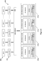
- FIG. 4 another example system for virtualization of an array of memristive DPEs is illustrated.
- the single memristive DPE 110 of the example system 100 described above may be replaced or appended with multiple physical memristive DPEs 410a-d.
- four physical memristive DPEs 410a-d are illustrated. In other examples, any practical number of physical memristive DPEs 410a-d may be provided.
- the example system 400 of Figure 4 allows formation of a virtual platform capable of managing multiple physical memristive DPEs and operating at rack-scale.
- multiple or numerous physical memristive DPEs 410a-d, as well as their resources may be pooled together to provide a large resource pool.
- the pool of memristive DPEs 410a-d and/or the pool of DPE resources of the memristive DPEs 410a-d may be managed by a DPE grid manager 420.
- the DPE grid manager 420 is an external component that uses administration interfaces to manage multiple memristive DPEs 410a-d and provide OS-like services to DPE users 440 through virtual DPEs 430.
- the memristive DPEs 410 are dynamically requested, allocated and deallocated by a user or tenant (e.g., a virtual DPE 430) via the DPE grid manager 420.
- Figure 5 illustrates the example system 100 of Figure 1 with a user 170 accessing the physical memristive DPE 110 via a virtual DPE 160b through the corresponding replicated interface 150b.
- the user may access a shared resource, such as the physical memristive DPE 110, in a secure manner by exchanging information with the memristive DPE in encrypted form.
- data uploaded by the user may be encrypted data. Encryption of the information may be decrypted by the DPE resource 120 of the memristive DPE 110 using encryption key provided by the user 170.
- the memristive DPE 110 may support the use of encrypted data using user-supplied encryption key on a layer-by-layer basis.
- data may be encrypted with a user-supplied key using a symmetric encryption algorithm such as AES.
- the memristive DPE 110 may transparently decrypt the input data just before processing on a tile and may re-encrypt the output data before it leaves the tile.
- encryption provides security to the user 170 of the shared memristive DPE 110, such as in a cloud environment.
- encryption protects the user's information and activity from users of other virtual DPE's, such as virtual DPE's 160a, as well as an administrator of the memristive DPE, such as administrator 190 illustrated in Figure 5 .
- the administrator 190 may be provided to control access to the memristive DPE 110.
- the user 170 may submit a request to the administrator 190.
- the administrator 190 may enable the user 170 to access the memristive DPE and to, for example, establish a virtual DPE session.
- the administrator 190 may impose limitations on access by the user 170, such as time limits on the virtual DPE session, for example.
- the encryption of information from the user 170 prevents the administrator 190, or any other entity, from accessing the user's information.
- the example method 600 may be implemented in, for example, the controller 140 of the physical memristive DPE 110 or by another processor.
- the example method 600 includes replicating at least one external interface of a memristive DPE (block 610).
- each replicated interface corresponds to a virtual DPE
- each virtual DPE corresponds to a stream layer for access to a resource of the memristive DPE.
- the example method further includes scheduling timeslots for access to the DPE for stream layers corresponding to the virtual DPEs (block 620).
- the physical memristive DPE may include a controller with a scheduler to dynamically select, on each timeslot, the stream layer, or virtual DPE, to run via the appropriate replicated interface.
- the scheduler may support any of a variety of scheduling algorithms, such as round robin and weighted round robin, for example.
- the system 700 includes a processor 710 and a non-transitory computer-readable storage medium 720.
- the computer-readable storage medium 720 includes example instructions 721-722 executable by the processor 710 to perform various functionalities described herein.
- the non-transitory computer-readable storage medium 720 may be any of a variety of storage devices including, but not limited to, a random access memory (RAM) a dynamic RAM (DRAM), static RAM (SRAM), flash memory, read-only memory (ROM), programmable ROM (PROM), electrically erasable PROM (EEPROM), or the like.
- the processor 710 may be a general purpose processor, special purpose logic, or the like.
- the example instructions include schedule timeslots to virtual dot product engines instructions 721.
- a physical memristive DPE may be coupled to at least one replicated interface, each replicated interface corresponding to a virtual DPE, or stream layer. Timeslots may be scheduled to virtual dot product engines (DPEs) through corresponding replicated interfaces. Each replicated interface may couple the corresponding virtual DPE to a physical memristive DPE.
- DPEs virtual dot product engines
- the example instructions further include instructions 722 to allocate DPE resources to a virtual DPE through replicated instructions.
- resources of the physical memristive DPE may be selectively allocated to a virtual DPE for each timeslot.
Landscapes
- Engineering & Computer Science (AREA)
- Software Systems (AREA)
- Theoretical Computer Science (AREA)
- Physics & Mathematics (AREA)
- General Engineering & Computer Science (AREA)
- General Physics & Mathematics (AREA)
- Mathematical Physics (AREA)
- Computing Systems (AREA)
- Computer Security & Cryptography (AREA)
- Computational Mathematics (AREA)
- Mathematical Optimization (AREA)
- Pure & Applied Mathematics (AREA)
- Data Mining & Analysis (AREA)
- Computer Hardware Design (AREA)
- Mathematical Analysis (AREA)
- Computer Networks & Wireless Communication (AREA)
- Signal Processing (AREA)
- Algebra (AREA)
- Databases & Information Systems (AREA)
- Storage Device Security (AREA)
- Micromachines (AREA)
Abstract
An example system includes at least one memristive dot product engine (DPE) having at least one resource, the DPE further having a physical interface and a controller, the controller being communicatively coupled to the physical interface, the physical interface to communicate with the controller to access the DPE, and at least one replicated interface, each replicated interface being associated with a virtual DPE, the replicated interface with communicatively coupled to the controller. The controller is to allocate timeslots to the virtual DPE through the associated replicated interface to allow the virtual DPE access to the at least one resource.
Description
- Resistive memory elements often referred to as memristors are devices that may be programmed to different resistive states by applying electrical voltage or currents to the memristors. Crossbar arrays of memristors may be used in a variety of applications, including non-volatile memory, programmable logic, etc. In this regard, a memristive crossbar array may include a number of row lines and a number of column lines intersecting the row lines. One application of such an arrangement is a memristive dot product engine.
- For a more complete understanding of various examples, reference is now made to the following description taken in connection with the accompanying drawings in which:
-
Figure 1 illustrates an example system for virtualization of a memristive dot product engine (DPE); -
Figure 2 illustrates the example system ofFigure 1 with an example resource of the memristive DPE; -
Figure 3 illustrates the example system ofFigure 2 with an example detailed illustration of a tile in the resource of the memristive DPE; -
Figure 4 illustrates another example system for virtualization of an array of memristive DPEs; -
Figure 5 illustrates another example system for virtualization of a memristive DPE with encrypted data exchange; -
Figure 6 is a flowchart illustrating an example method; and -
Figure 7 illustrates a block diagram of an example system with a computer-readable storage medium including instructions executable by a processor for virtualization of a memristive DPE. - Various examples described herein relate to virtualization of a memristive dot product engine (DPE). In accordance with various examples described herein, virtualization of a DPE allows sharing of DPE resources by multiple users, even if those users are distrusting of each other. Virtualization of the DPE is achieved by replicating an interface of a physical DPE for each virtual DPE, or each DPE stream layer. In this regard, a stream layer refers to a session of a virtual DPE. In various examples, a scheduler of the physical DPE may allocate various time slices to various sessions, or stream layers. The replicated interfaces may be implemented as hardware, software or firmware in a manner similar to, or identical to, an interface of the physical DPE. The replicated interfaces are communicatively coupled to a controller of the physical DPE. The controller includes the scheduler to allocate timeslots to the virtual DPEs through the replicated interfaces. Thus, each user of a virtual DPE is isolated from users of other virtual DPEs. In some examples, communication between a user of the virtual DPE and the controller of the physical DPE is encrypted to enhance security. In this regard, an associated security key is provided by the user for decryption of the information at the physical DPE or at a DPE resource. Thus, information transmitted by the user may be protected from other users (e.g., users of other virtual DPEs) or an administrator of the physical DPE, for example.
- As used herein, a "dot product" refers broadly to the product of two vectors to form a scalar whose value is the product of the magnitudes of the vectors and the cosine of the angle between them. In the context of a memristive DPE, a dot product may be determined by applying a voltage to an input and multiplying the voltage by a conductance that is programmed into the DPE to get a current, as described in greater detail below with reference to
Figure 3 . - Referring now to
Figure 1 , an example system for virtualization of a memristive DPE is illustrated. Theexample system 100 includes amemristive DPE 110. As used herein, the term "memristor" may refer to a passive two-terminal circuit element that maintains a functional relationship between the time integral of current, and the time integral of voltage. Further, the term "memristive dot product engine" refers broadly to a dot product engine that includes a memristive crossbar array. - The example
memristive DPE 110 ofFigure 1 includes at least oneDPE resource 120. In various examples, theDPE resource 120 includes at least one memristive crossbar array which includes a number of row lines and a number of column lines intersecting the row lines. Anexample DPE resource 120 is described below in greater detail with reference toFigures 2 and3 . - The example
memristive DPE 110 ofFigure 1 further includes aninterface 130. In various examples, theinterface 130 is an input/output interface which allows theDPE 110 to be communicatively coupled to an external component. For example, a processor of a computing system may be coupled to theDPE 110 through theinterface 130 and may obtain access to theDPE resource 120. - In the
example system 100 ofFigure 1 , the examplememristive DPE 110 is further provided with acontroller 140. In various examples, thecontroller 140 may control various aspects of the examplememristive DPE 110. For example, thecontroller 140 may determine which resources are available to or allocated for various tasks or users. Thecontroller 140 in theexample system 100 ofFigure 1 includes ascheduler 142 and aresource manager 144. Thecontroller 140, or thescheduler 142 of thecontroller 140, is communicatively coupled to theexternal interface 130 to facilitate access to theDPE resource 120 by an external component, for example. Theresource manager 144 may monitor availability of various portions of the DPEresource 120 and may selectively allocate theresource 120 to entities, such as the external component described above. - In various examples, the
memristive DPE 110 is virtualized by replicating theexternal interface 130 of the physicalmemristive DPE 110. As illustrated inFigure 1 , theexample system 100 includes replicatedinterfaces 150a-n. In various examples, any practical number of replicatedinterfaces 150a-n may be made available. In some examples, thesystem 100 may set a maximum number of replicated interfaces 150 to allow sufficient availability of resources. - Replication provides a mechanism by which a single physical
memristive DPE 110 may appear as multiple separate physical devices to various users. In this regard, the physicalmemristive DPE 110 provides a unique memory space, work queues, interrupts, and command processing for each user via each replicated interface. In one example, the physicalmemristive DPE 110 is a Peripheral Component Interconnect Express (PCIe)-based DPE that can be configured to appear in the PCI configuration space as multiple functions. Each replicated interface provides its own configuration space. Thus, the physicalmemristive DPE 110 appears as separate, multiple PCIe devices. - Virtualization of the physical
memristive DPE 110 may be achieved by providing a separate stream layer for each replicated interface 150. Thus, a user associated with a particular replicated interface 150 may access the resources (e.g. the DPE resource 120) of the physicalmemristive DPE 110 as a virtual DPE 160 through the corresponding replicated interface 150. In this regard, each replicatedinterface 150a-n is communicatively coupled to thecontroller 140, similar to the coupling of thecontroller 140 with theexternal interface 130 of the physicalmemristive DPE 110. - For example, in the example of
Figure 1 , a user may access theDPE resource 120 of the physicalmemristive DPE 110 through the first replicatedinterface 150a. In this regard, the first replicatedinterface 150a may be associated with a correspondingvirtual DPE 160a. The correspondingvirtual DPE 160a is accommodated by thecontroller 140 of the physicalmemristive DPE 110 as a distinct stream layer. In various examples, thescheduler 142 may allocate timeslots, or time slices, to the various stream layers orvirtual DPEs 160a-n. - In various examples, the
scheduler 142 dynamically selects, on each timeslot, the stream layer, or virtual DPE 160, to run via the appropriate replicated interface 150. Thescheduler 140 may support any of a variety of scheduling algorithms, such as round robin and weighted round robin, for example. - The
resource manager 144 of thecontroller 140 in theexample system 100 ofFigure 1 may selectively allocate the at least one resource to a virtual DPE during each timeslot. For example, theresource manager 144 may dynamically select the scheduling algorithm and manage the type of actions a user, through the appropriate virtual DPE 160, is allowed to perform. For example, a particular stream layer, or virtual DPE, may be prevented from reconfiguring the physical memristive DPE. - In various examples, the
scheduler 142 and theresource manager 144 may facilitate removal of layers from the scheduling algorithm. For example, in some cases, the entirety of thephysical memristive DPE 110 may be allocated to a particular stream layer for an extended number of timeslots. In this regard, the particular stream layer may be a virtual DPE 160 or an external component coupled to thephysical memristive DPE 110 through theexternal interface 130. In this regard, use of time slots or time slicing may also be disabled for the extended period. - Referring now to
Figure 2 , theexample system 100 ofFigure 1 is illustrated with anexample DPE resource 120 of thememristive DPE 110. In the example ofFigure 2 , theDPE resource 120 includes a number oftiles 122. In various examples, eachtile 122 is a subset of theDPE resource 120. A number oftiles 122 may be allocated to a particular task or stream layer, for example. In this regard, theDPE resource 120 may be divided to accommodate and support any number of tasks simultaneously. Further, thetiles 122 may be arranged in any of a variety of manners. For example, in the example ofFigure 2 , thetiles 122 are arranged in an array. - Referring now to
Figure 3 , the example system ofFigure 2 is illustrated with an example detailed illustration of atile 122 in theDPE resource 120 of thememristive DPE 110. Theexample tile 300 ofFigure 3 is an example architecture using a memristive crossbar array. In this regard, theexample tile 300 ofFigure 3 includes a memory buffer 310 (e.g., an enhanced dynamic random access memory, or eDRAM, buffer), as well as various other components such as anoutput register 312 and a shift-and-add unit 314.Memory buffer 310 may be, for example, a DRAM buffer or another type and may be used to store input values provided to thecrossbar array 322 described below. Further, theoutput register 312 may be used to aggregate results from the shift-and-add unit 314, as also described below. Each tile of theDPE resource 120, such as thetile 300, is provided with acontrol unit 316 which may be communicatively coupled to thecontroller 140 of thememristive DPE 110. In this regard, eachtile 122 is coupled to thecontroller 140 through a bus, providing connections between thecontroller 140 and various components of eachtile 122, such as thecontrol unit 316. Theexample tile 300 is provided with a set of components, referred to as in-situ multiply accumulate (IMA)units 320. In the example ofFigure 3 , thetile 300 is provided with eightIMA units 320. - One example architecture of an
IMA unit 320 is illustrated in detail inFigure 3 . In the illustrated example, theIMA unit 320 is provided with a number ofmemristor crossbar units 322. In the example ofFigure 3 , theIMA unit 320 is provided with fourmemristor crossbar units 322. Eachcrossbar unit 322 is coupled to a digital-to-analog converter (DAC) 324 and a sample-and-hold unit 326. Signals from theDACs 324 may be combined (e.g., via an input register 328) and provided to a set of analog-to-digital converters (ADCs) 330. TheIMA unit 320 ofFigure 3 further includes acontrol unit 332 which may be communicatively coupled to thecontroller 140 of thememristive DPE 110, for example, through thecontrol unit 316 of thetile 300. TheIMA unit 320 further includes various other components, such as anoutput register 334 and a shift-and-add unit 336. In various examples, theoutput register 334 of theIMA unit 320 may be part of or coupled to theoutput register 312 of thetile 300. Similarly, the shift-and-add unit 336 of theIMA unit 320 may be part of or coupled to the shift-and-add unit 314 of thetile 300. - In various examples, each
memristive crossbar array 322 includes a number of row lines and a number ofcolumn lines 342 intersecting the row lines 344. Amemristive memory element 346 is located at each intersection of a row line 344 and acolumn line 342. Eachmemristive element 346 receives a programming vector signal to represent a value within a matrix, a reference vector signal, and an operating vector signal to represent a vector value to be multiplied by the matrix. In this regard, the row lines 344 of thecrossbar array 322 are coupled to theDACs 322 to provide the row lines 344 with aninput voltage 348, in accordance with input values stored in thememory buffer 310, forming the input vector signal. Further, eachcolumn line 342 is coupled to the sample-and-hold unit 326 to receive a current flow from the column lines 342. Each sample-and-hold unit 326 is coupled to anADC 330 and shift-and-add unit 336 to convert the electrical current in thecolumn line 342 to a voltage signal. In various examples of theDPE 110, vector and matrix multiplications are performed by applying the input voltages to the row lines 344 and collecting the currents through thecolumn lines 342 and measuring the output voltage. - Thus, dot-product operations may be performed on the
crossbar arrays 322, and the results are sent to theADCs 330 and aggregated in the output registers 334 or output registers 312. The aggregated result is sent through asigmoid operator 313 and stored in thememory buffer 310 for further processing, for example. - Referring now to
Figure 4 , another example system for virtualization of an array of memristive DPEs is illustrated. In theexample system 400 ofFigure 4 , thesingle memristive DPE 110 of theexample system 100 described above may be replaced or appended with multiple physical memristive DPEs 410a-d. In theexample system 400 ofFigure 4 , four physical memristive DPEs 410a-d are illustrated. In other examples, any practical number of physical memristive DPEs 410a-d may be provided. - The
example system 400 ofFigure 4 allows formation of a virtual platform capable of managing multiple physical memristive DPEs and operating at rack-scale. In this regard, multiple or numerous physical memristive DPEs 410a-d, as well as their resources, may be pooled together to provide a large resource pool. The pool of memristive DPEs 410a-d and/or the pool of DPE resources of the memristive DPEs 410a-d may be managed by aDPE grid manager 420. In various examples, theDPE grid manager 420 is an external component that uses administration interfaces to manage multiple memristive DPEs 410a-d and provide OS-like services toDPE users 440 throughvirtual DPEs 430. In this regard, the memristive DPEs 410 are dynamically requested, allocated and deallocated by a user or tenant (e.g., a virtual DPE 430) via theDPE grid manager 420. - Referring now to
Figure 5 , another example system for virtualization of a memristive DPE with encrypted data exchange is illustrated.Figure 5 illustrates theexample system 100 ofFigure 1 with auser 170 accessing thephysical memristive DPE 110 via avirtual DPE 160b through the corresponding replicatedinterface 150b. As illustrated inFigure 5 , the user may access a shared resource, such as thephysical memristive DPE 110, in a secure manner by exchanging information with the memristive DPE in encrypted form. For example, data uploaded by the user may be encrypted data. Encryption of the information may be decrypted by theDPE resource 120 of thememristive DPE 110 using encryption key provided by theuser 170. - For sensitive workloads, the
memristive DPE 110 may support the use of encrypted data using user-supplied encryption key on a layer-by-layer basis. Thus, instead of each stream layer user supplying data to the DPE in plaintext, data may be encrypted with a user-supplied key using a symmetric encryption algorithm such as AES. Thememristive DPE 110 may transparently decrypt the input data just before processing on a tile and may re-encrypt the output data before it leaves the tile. - Use of encryption provides security to the
user 170 of the sharedmemristive DPE 110, such as in a cloud environment. In this regard, encryption protects the user's information and activity from users of other virtual DPE's, such as virtual DPE's 160a, as well as an administrator of the memristive DPE, such asadministrator 190 illustrated inFigure 5 . In the example illustrated inFigure 5 , theadministrator 190 may be provided to control access to thememristive DPE 110. In this regard, when theuser 170 desires access to thememristive DPE 110 to, for example, establish a virtual DPE session, theuser 170 may submit a request to theadministrator 190. If credentials provided by theuser 170 are satisfactory, theadministrator 190 may enable theuser 170 to access the memristive DPE and to, for example, establish a virtual DPE session. Theadministrator 190 may impose limitations on access by theuser 170, such as time limits on the virtual DPE session, for example. As noted above, the encryption of information from theuser 170 prevents theadministrator 190, or any other entity, from accessing the user's information. - Referring now to
Figure 6 , a flowchart illustrates an example method for using virtualized DPE. Theexample method 600 may be implemented in, for example, thecontroller 140 of the physicalmemristive DPE 110 or by another processor. Theexample method 600 includes replicating at least one external interface of a memristive DPE (block 610). In this regard, each replicated interface corresponds to a virtual DPE, and each virtual DPE corresponds to a stream layer for access to a resource of the memristive DPE. - The example method further includes scheduling timeslots for access to the DPE for stream layers corresponding to the virtual DPEs (block 620). As described above, in some examples, the physical memristive DPE may include a controller with a scheduler to dynamically select, on each timeslot, the stream layer, or virtual DPE, to run via the appropriate replicated interface. The scheduler may support any of a variety of scheduling algorithms, such as round robin and weighted round robin, for example.
- Referring now to
Figure 7 , a block diagram of an example system is illustrated with a non-transitory computer-readable storage medium including instructions executable by a processor for particle sorting. Thesystem 700 includes aprocessor 710 and a non-transitory computer-readable storage medium 720. The computer-readable storage medium 720 includes example instructions 721-722 executable by theprocessor 710 to perform various functionalities described herein. In various examples, the non-transitory computer-readable storage medium 720 may be any of a variety of storage devices including, but not limited to, a random access memory (RAM) a dynamic RAM (DRAM), static RAM (SRAM), flash memory, read-only memory (ROM), programmable ROM (PROM), electrically erasable PROM (EEPROM), or the like. In various examples, theprocessor 710 may be a general purpose processor, special purpose logic, or the like. - The example instructions include schedule timeslots to virtual dot
product engines instructions 721. In this regard, a physical memristive DPE may be coupled to at least one replicated interface, each replicated interface corresponding to a virtual DPE, or stream layer. Timeslots may be scheduled to virtual dot product engines (DPEs) through corresponding replicated interfaces. Each replicated interface may couple the corresponding virtual DPE to a physical memristive DPE. - The example instructions further include
instructions 722 to allocate DPE resources to a virtual DPE through replicated instructions. In this regard, resources of the physical memristive DPE may be selectively allocated to a virtual DPE for each timeslot. - The foregoing description of various examples has been presented for purposes of illustration and description. The foregoing description is not intended to be exhaustive or limiting to the examples disclosed, and modifications and variations are possible in light of the above teachings or may be acquired from practice of various examples. The examples discussed herein were chosen and described in order to explain the principles and the nature of various examples of the present disclosure and its practical application to enable one skilled in the art to utilize the present disclosure in various examples and with various modifications as are suited to the particular use contemplated. The features of the examples described herein may be combined in all possible combinations of methods, apparatus, modules, systems, and computer program products.
- It is also noted herein that while the above describes examples, these descriptions should not be viewed in a limiting sense. Rather, there are several variations and modifications which may be made without departing from the scope as defined in the appended claims.
Claims (14)
- A system, comprising:at least one memristive dot product engine (DPE) having at least one resource, the DPE further having a physical interface and a controller, the controller being communicatively coupled to the physical interface, the physical interface to communicate with the controller to access the DPE; andat least one replicated interface, each replicated interface being associated with a virtual DPE, the replicated interface communicatively coupled to the controller,wherein the controller is to allocate timeslots to the virtual DPE through the associated replicated interface to allow the virtual DPE access to the at least one resource.
- The system of claim 1, wherein the controller comprises:a scheduler communicatively coupled to the physical interface and the at least one replicated interface, the scheduler being to identify a virtual DPE for each timeslot; anda resource manager to selectively allocate the at least one resource to a virtual DPE during each timeslot.
- The system of claim 1, wherein the memristive DPE includes a memristive crossbar array having a number of row lines, a number of column lines intersecting the row lines, and memristive memory elements located at each intersection of a row line and a column line.
- The system of claim 1, wherein the at least one memristive dot product engine (DPE) includes multiple memristive DPEs, the system further comprising:
a DPE grid manager coupled to each of the multiple memristive DPEs, the DPE grid manager to pool the multiple DPEs for pooling of the resources of the multiple DPEs. - The system of claim 1, wherein at least one replicated interface is to exchange information with the memristive DPE in encrypted form, the information in encrypted form to be decrypted by an encryption key from a user associated with the virtual DPE corresponding to the replicated interface.
- A method, comprising:replicating at least one external interface of a memristive dot product engine (DPE), each replicated interface corresponding to a virtual DPE, each virtual DPE corresponding to a stream layer for access to a resource of the DPE; andscheduling timeslots for access to the DPE for stream layers corresponding to the virtual DPEs.
- The method of claim 6, further comprising:
selectively allocating the resource of the memristive DPE to the virtual DPEs at each timeslot. - The method of claim 6, wherein the memristive DPE includes a memristive crossbar array having a number of row lines, a number of column lines intersecting the row lines, and memristive memory elements located at each intersection of a row line and a column line.
- The method of claim 6, further comprising:
pooling multiple memristive DPEs to pool resources of the multiple memristive DPEs for allocation at the timeslots. - The method of claim 6, further comprising:
receiving information from a replicated interface in encrypted form, the information in encrypted form to be decrypted by an encryption key from a user associated with the virtual DPE corresponding to the replicated interface. - A non-transitory computer-readable storage medium encoded with instructions executable by a processor of a computing system, the computer-readable storage medium comprising instructions to:schedule timeslots to virtual dot product engines (DPEs) through corresponding replicated interfaces, each replicated interface coupling the corresponding virtual DPE to a physical memristive DPE; andselectively allocating resources of the physical memristive DPE to a virtual DPE for each timeslot.
- The non-transitory computer-readable storage medium of claim 11, wherein the physical memristive DPE includes a memristive crossbar array having a number of row lines, a number of column lines intersecting the row lines, and memristive memory elements located at each intersection of a row line and a column line.
- The non-transitory computer-readable storage medium of claim 11, further comprising instructions to:
pool multiple physical memristive DPEs to pool resources of the multiple physical memristive DPEs for allocation at the timeslots. - The non-transitory computer-readable storage medium of claim 11, further comprising instructions to:
receive information from a replicated interface in encrypted form, the information in encrypted form to be decrypted by an encryption key from a user associated with the virtual DPE corresponding to the replicated interface.
Applications Claiming Priority (1)
| Application Number | Priority Date | Filing Date | Title |
|---|---|---|---|
| US15/884,030 US10740125B2 (en) | 2018-01-30 | 2018-01-30 | Memristive dot product engine virtualization |
Publications (1)
| Publication Number | Publication Date |
|---|---|
| EP3518108A1 true EP3518108A1 (en) | 2019-07-31 |
Family
ID=65279408
Family Applications (1)
| Application Number | Title | Priority Date | Filing Date |
|---|---|---|---|
| EP19154343.8A Withdrawn EP3518108A1 (en) | 2018-01-30 | 2019-01-29 | Memristive dot product engine virtualization |
Country Status (3)
| Country | Link |
|---|---|
| US (1) | US10740125B2 (en) |
| EP (1) | EP3518108A1 (en) |
| CN (1) | CN110097909A (en) |
Families Citing this family (4)
| Publication number | Priority date | Publication date | Assignee | Title |
|---|---|---|---|---|
| US10740125B2 (en) * | 2018-01-30 | 2020-08-11 | Hewlett Packard Enterprise Development Lp | Memristive dot product engine virtualization |
| US10496374B2 (en) * | 2018-03-22 | 2019-12-03 | Hewlett Packard Enterprise Development Lp | Crossbar array operations using ALU modified signals |
| US20220019441A1 (en) * | 2020-07-14 | 2022-01-20 | The Regents Of The University Of California | Circuits, methods, and articles of manufacture for hyper-dimensional computing systems and related applications |
| US11947928B2 (en) | 2020-09-10 | 2024-04-02 | Hewlett Packard Enterprise Development Lp | Multi-die dot-product engine to provision large scale machine learning inference applications |
Family Cites Families (12)
| Publication number | Priority date | Publication date | Assignee | Title |
|---|---|---|---|---|
| US8898324B2 (en) | 2010-06-24 | 2014-11-25 | International Business Machines Corporation | Data access management in a hybrid memory server |
| CN105579959B (en) | 2013-09-24 | 2019-06-07 | 渥太华大学 | Hardware accelerator virtualization |
| CN103617329A (en) * | 2013-12-12 | 2014-03-05 | 西安工业大学 | Assembly time evaluating method based on artificial neural network and virtual assembly |
| JP6333477B2 (en) * | 2014-10-23 | 2018-05-30 | ヒューレット パッカード エンタープライズ デベロップメント エル ピーHewlett Packard Enterprise Development LP | Memristive crossbar array for determining dot product |
| WO2016068953A1 (en) * | 2014-10-30 | 2016-05-06 | Hewlett Packard Enterprise Development Lp | Double bias memristive dot product engine for vector processing |
| US9947405B2 (en) * | 2014-11-18 | 2018-04-17 | Hewlett Packard Enterprise Development Lp | Memristive dot product engine with a nulling amplifier |
| US10275247B2 (en) * | 2015-03-28 | 2019-04-30 | Intel Corporation | Apparatuses and methods to accelerate vector multiplication of vector elements having matching indices |
| US9847980B2 (en) | 2015-06-17 | 2017-12-19 | Microsoft Technology Licensing, Llc | Protecting communications with hardware accelerators for increased workflow security |
| CN107636640B (en) * | 2016-01-30 | 2021-11-23 | 慧与发展有限责任合伙企业 | Dot product engine, memristor dot product engine and method for calculating dot product |
| US10387037B2 (en) * | 2016-12-31 | 2019-08-20 | Intel Corporation | Microarchitecture enabling enhanced parallelism for sparse linear algebra operations having write-to-read dependencies |
| US11216722B2 (en) * | 2016-12-31 | 2022-01-04 | Intel Corporation | Hardware accelerator template and design framework for implementing recurrent neural networks |
| US10740125B2 (en) * | 2018-01-30 | 2020-08-11 | Hewlett Packard Enterprise Development Lp | Memristive dot product engine virtualization |
-
2018
- 2018-01-30 US US15/884,030 patent/US10740125B2/en active Active
-
2019
- 2019-01-29 CN CN201910085074.2A patent/CN110097909A/en active Pending
- 2019-01-29 EP EP19154343.8A patent/EP3518108A1/en not_active Withdrawn
Non-Patent Citations (1)
| Title |
|---|
| BRUEL PEDRO ET AL: "Generalize or Die: Operating Systems Support for Memristor-Based Accelerators", 2017 IEEE INTERNATIONAL CONFERENCE ON REBOOTING COMPUTING (ICRC), IEEE, 8 November 2017 (2017-11-08), pages 1 - 8, XP033273693, DOI: 10.1109/ICRC.2017.8123649 * |
Also Published As
| Publication number | Publication date |
|---|---|
| CN110097909A (en) | 2019-08-06 |
| US20190235889A1 (en) | 2019-08-01 |
| US10740125B2 (en) | 2020-08-11 |
Similar Documents
| Publication | Publication Date | Title |
|---|---|---|
| US12106134B2 (en) | Mechanism to dynamically allocate physical storage device resources in virtualized environments | |
| US10740125B2 (en) | Memristive dot product engine virtualization | |
| KR102191408B1 (en) | Neural network processor | |
| CN107688492B (en) | Resource control method and device and cluster resource management system | |
| US11416396B2 (en) | Volume tiering in storage systems | |
| US9338228B1 (en) | I/O scheduling and load balancing across the multiple nodes of a clustered environment utilizing data volume based scheduling priorities | |
| US9501325B2 (en) | System and method for shared utilization of virtualized computing resources | |
| US10715587B2 (en) | System and method for load balancing computer resources | |
| WO2018036103A1 (en) | Virtual machine creation method and system, and host computer | |
| WO2016138638A1 (en) | Resource allocation method and apparatus for virtual machines | |
| JP2018073414A5 (en) | ||
| US10467052B2 (en) | Cluster topology aware container scheduling for efficient data transfer | |
| AU2014295583A1 (en) | Resource management for peripheral component interconnect-express domains | |
| US9619248B2 (en) | Configuration manager and method for configuring a host system for processing a processing job in a virtual data-processing environment | |
| US11973694B1 (en) | Ad-hoc allocation of in-network compute-resources | |
| US9584594B2 (en) | Dynamic provisioning of processing resources in a virtualized computational architecture | |
| US10079777B2 (en) | Apparatus, systems, and methods of allocating heterogeneous resources | |
| US9535859B2 (en) | Sharing message-signaled interrupts between peripheral component interconnect (PCI) I/O devices | |
| WO2024245536A1 (en) | Disaggregated compute system and method | |
| US10367883B2 (en) | Computing resource management using dedicated leadership pool | |
| US8782304B2 (en) | Method for enabling several virtual processing units to directly and concurrently access a peripheral unit | |
| CN115658174B (en) | Method, device, equipment and medium for configuring system resources | |
| EP4498246A1 (en) | Virtual infrastructure provisioning on government certification compliant and non-compliant endpoints based on configuration | |
| CN121935912A (en) | Trusted root architecture construction method, trusted system application method and device |
Legal Events
| Date | Code | Title | Description |
|---|---|---|---|
| PUAI | Public reference made under article 153(3) epc to a published international application that has entered the european phase |
Free format text: ORIGINAL CODE: 0009012 |
|
| STAA | Information on the status of an ep patent application or granted ep patent |
Free format text: STATUS: THE APPLICATION HAS BEEN PUBLISHED |
|
| AK | Designated contracting states |
Kind code of ref document: A1 Designated state(s): AL AT BE BG CH CY CZ DE DK EE ES FI FR GB GR HR HU IE IS IT LI LT LU LV MC MK MT NL NO PL PT RO RS SE SI SK SM TR |
|
| AX | Request for extension of the european patent |
Extension state: BA ME |
|
| STAA | Information on the status of an ep patent application or granted ep patent |
Free format text: STATUS: THE APPLICATION IS DEEMED TO BE WITHDRAWN |
|
| 18D | Application deemed to be withdrawn |
Effective date: 20200201 |