EP3517889A1 - Measurement device - Google Patents
Measurement device Download PDFInfo
- Publication number
- EP3517889A1 EP3517889A1 EP17852956.6A EP17852956A EP3517889A1 EP 3517889 A1 EP3517889 A1 EP 3517889A1 EP 17852956 A EP17852956 A EP 17852956A EP 3517889 A1 EP3517889 A1 EP 3517889A1
- Authority
- EP
- European Patent Office
- Prior art keywords
- convex portion
- measuring device
- unit
- morphology
- fixing member
- Prior art date
- Legal status (The legal status is an assumption and is not a legal conclusion. Google has not performed a legal analysis and makes no representation as to the accuracy of the status listed.)
- Granted
Links
Images



Classifications
-
- G—PHYSICS
- G01—MEASURING; TESTING
- G01B—MEASURING LENGTH, THICKNESS OR SIMILAR LINEAR DIMENSIONS; MEASURING ANGLES; MEASURING AREAS; MEASURING IRREGULARITIES OF SURFACES OR CONTOURS
- G01B11/00—Measuring arrangements characterised by the use of optical techniques
- G01B11/24—Measuring arrangements characterised by the use of optical techniques for measuring contours or curvatures
-
- A—HUMAN NECESSITIES
- A61—MEDICAL OR VETERINARY SCIENCE; HYGIENE
- A61B—DIAGNOSIS; SURGERY; IDENTIFICATION
- A61B5/00—Measuring for diagnostic purposes; Identification of persons
- A61B5/0059—Measuring for diagnostic purposes; Identification of persons using light, e.g. diagnosis by transillumination, diascopy, fluorescence
- A61B5/0062—Arrangements for scanning
- A61B5/0064—Body surface scanning
-
- A—HUMAN NECESSITIES
- A61—MEDICAL OR VETERINARY SCIENCE; HYGIENE
- A61B—DIAGNOSIS; SURGERY; IDENTIFICATION
- A61B5/00—Measuring for diagnostic purposes; Identification of persons
- A61B5/103—Measuring devices for testing the shape, pattern, colour, size or movement of the body or parts thereof, for diagnostic purposes
- A61B5/107—Measuring physical dimensions, e.g. size of the entire body or parts thereof
- A61B5/1077—Measuring of profiles
-
- A—HUMAN NECESSITIES
- A61—MEDICAL OR VETERINARY SCIENCE; HYGIENE
- A61B—DIAGNOSIS; SURGERY; IDENTIFICATION
- A61B5/00—Measuring for diagnostic purposes; Identification of persons
- A61B5/103—Measuring devices for testing the shape, pattern, colour, size or movement of the body or parts thereof, for diagnostic purposes
- A61B5/107—Measuring physical dimensions, e.g. size of the entire body or parts thereof
- A61B5/1079—Measuring physical dimensions, e.g. size of the entire body or parts thereof using optical or photographic means
-
- A—HUMAN NECESSITIES
- A61—MEDICAL OR VETERINARY SCIENCE; HYGIENE
- A61B—DIAGNOSIS; SURGERY; IDENTIFICATION
- A61B5/00—Measuring for diagnostic purposes; Identification of persons
- A61B5/44—Detecting, measuring or recording for evaluating the integumentary system, e.g. skin, hair or nails
- A61B5/441—Skin evaluation, e.g. for skin disorder diagnosis
- A61B5/444—Evaluating skin marks, e.g. mole, nevi, tumour, scar
-
- A—HUMAN NECESSITIES
- A61—MEDICAL OR VETERINARY SCIENCE; HYGIENE
- A61B—DIAGNOSIS; SURGERY; IDENTIFICATION
- A61B5/00—Measuring for diagnostic purposes; Identification of persons
- A61B5/70—Means for positioning the patient in relation to the detecting, measuring or recording means
-
- A—HUMAN NECESSITIES
- A61—MEDICAL OR VETERINARY SCIENCE; HYGIENE
- A61B—DIAGNOSIS; SURGERY; IDENTIFICATION
- A61B5/00—Measuring for diagnostic purposes; Identification of persons
- A61B5/74—Details of notification to user or communication with user or patient; User input means
- A61B5/742—Details of notification to user or communication with user or patient; User input means using visual displays
- A61B5/7445—Display arrangements, e.g. multiple display units
-
- G—PHYSICS
- G01—MEASURING; TESTING
- G01B—MEASURING LENGTH, THICKNESS OR SIMILAR LINEAR DIMENSIONS; MEASURING ANGLES; MEASURING AREAS; MEASURING IRREGULARITIES OF SURFACES OR CONTOURS
- G01B21/00—Measuring arrangements or details thereof, where the measuring technique is not covered by the other groups of this subclass, unspecified or not relevant
- G01B21/02—Measuring arrangements or details thereof, where the measuring technique is not covered by the other groups of this subclass, unspecified or not relevant for measuring length, width, or thickness
- G01B21/04—Measuring arrangements or details thereof, where the measuring technique is not covered by the other groups of this subclass, unspecified or not relevant for measuring length, width, or thickness by measuring coordinates of points
- G01B21/047—Accessories, e.g. for positioning, for tool-setting, for measuring probes
-
- A—HUMAN NECESSITIES
- A61—MEDICAL OR VETERINARY SCIENCE; HYGIENE
- A61B—DIAGNOSIS; SURGERY; IDENTIFICATION
- A61B2503/00—Evaluating a particular growth phase or type of persons or animals
- A61B2503/40—Animals
Definitions
- the present invention relates to a measuring device that measures the morphology of a convex portion, such as a tumor formed on the skin of, for example, an animal.
- a method including forming a tumor on the skin of a small animal, such as a mouse, putting a candidate compound into the tumor, and observing a reduction in the size of the tumor to evaluate a drug effect has been performed in the research and development of, for example, an anticancer drug.
- the size of the tumor has been measured using, for example, a measuring equipment, such as a vernier caliper.
- a measuring equipment such as a vernier caliper
- a method of fixing the vernier caliper to the tumor by an operator varies. For this reason, it is difficult to obtain objective measurement results.
- a so-called three-dimensional scanner which irradiates a tumor with light and measures the three-dimensional morphology of the tumor by detecting reflected light reflected from the tumor, is proposed in, for example, US2005/0084176A .
- the three-dimensional scanner disclosed in US2005/0084176A also has a problem that the same measurement results are not obtained according to a method of disposing a mouse and the range of the tumor to be irradiated with light even though the same tumor is measured.
- the size of the tumor needs to be measured plural times in time series.
- a method of disposing the mouse is performed or a range to be irradiated with light is set whenever the size of the tumor is measured, sufficient measurement accuracy cannot be obtained.
- the invention has been made in consideration of the above-mentioned problem, and an object of the invention is to provide a measuring device that can measure the morphology of a convex portion, such as a tumor formed on the skin of an animal, with high accuracy.
- a measuring device of the invention comprises a measuring unit that measures the morphology of a convex portion, and a position fixing unit that includes an opening in which the convex portion is to be disposed and a fixing member which includes the opening at a center thereof and against which a periphery of the convex portion is to be pressed.
- a size of the opening of the position fixing unit is capable of being changed.
- the fixing member may be provided with a stop mechanism that changes the size of the opening.
- the fixing member has a shape of a ring.
- stiffness of at least a portion of the fixing member against which the periphery of the convex portion is to be pressed is capable of being changed.
- a resin member is provided on the portion of the fixing member against which the periphery of the convex portion is to be pressed and a plurality of the resin members having different stiffness are adapted to be interchangeable.
- a maximum length of the opening of the position fixing unit is in the range of 1 mm to 10 cm.
- the measuring unit may set a base level on the basis of the fixing member and measure the morphology of the convex portion using the base level.
- the measuring unit may set a surface of the fixing member, against which the periphery of the convex portion is to be pressed, as the base level.
- the measuring device of the invention may further comprise a display control unit that acquires information about the morphology of the convex portion measured in time series by the measuring unit and displays the information about the morphology on the same screen or a plurality of screens so that the information about the morphologies are arranged in time series.
- the display control unit may display numerical data as the information about the morphology of the convex portion so that the numerical data are arranged in time series.
- the display control unit may display three-dimensional images of the convex portion as the information about the morphology of the convex portion so that the three-dimensional images of the convex portion are arranged in time series.
- the display control unit may display the three-dimensional images of the convex portion so that the three-dimensional images are aligned in a preset direction of the convex portion, in a case where the display control unit is to display the three-dimensional images of the convex portion so that the three-dimensional images of the convex portion are arranged in time series.
- the display control unit may display information about the morphology of the convex portion, which are measured under different conditions, on the same screen or a plurality of screens so that the information about the morphologies of the convex portion are arranged in time series.
- the measuring unit may irradiate the convex portion with light and measure the morphology of the convex portion by detecting reflected light reflected from the convex portion or light emitted from the convex portion.
- the measuring unit may scan the convex portion with laser light and detect reflected light reflected from the convex portion or light emitted from the convex portion due to scanning using the laser light.
- the position fixing unit that includes an opening in which the convex portion is to be disposed and a fixing member which includes the opening at a center thereof and against which the periphery of the convex portion is to be pressed. Accordingly, even in a case where an object to be measured is a soft mouse or the like, the disposition of the convex portion, such as a tumor, can be stabilized. Further, since the size of the opening of the position fixing unit is capable of being changed, it is possible to stably measure the tumor by changing the size of the opening according to the size of the tumor even in a case where a tumor of which the size is changed with the lapse of time is to be measured. Accordingly, it is possible to measure the morphology of the convex portion with higher accuracy than in the related art.
- Fig. 1 is a block diagram showing the schematic configuration of the bioinstrumentation system of this embodiment.
- the bioinstrumentation system of this embodiment measures the morphology of, for example, a convex portion, such as a tumor formed on the skin of an animal, and allows a display unit to display information about the morphology.
- the bioinstrumentation system of this embodiment comprises a measuring device 1 and a display device 2.
- the measuring device 1 comprises a measuring unit body 10 and a measurement result processing device 20.
- Fig. 2 is a diagram showing the specific configuration of the measuring unit body 10.
- the measuring unit body 10 and a measurement result calculation unit 21 to be described later form a measuring unit of the invention.
- the measuring unit body 10 comprises a light detection unit 11, a position fixing unit 15, a light detection unit-support part 17, and a fixing base 19.
- the light detection unit 11 comprises a light source unit 12, a condensing optical system 13, and a detection unit 14.
- the light source unit 12, the condensing optical system 13, and the detection unit 14 are received in a housing 11a.
- the housing 11a is formed of a member that blocks light, or the like.
- a through-hole 11b through which laser light L1 emitted from the light source unit 12 passes and a through-hole 11c through which reflected light L2 reflected from a convex portion as an object to be measured passes are formed in the housing 11a.
- the light source unit 12 comprises a laser light source and a scanning mechanism that applies laser light L1 emitted from the laser light source.
- the convex portion fixed to the position fixing unit 15 is irradiated with laser light L1 emitted from the light source unit 12.
- laser light L1 emitted from the laser light source is applied by the scanning mechanism, so that the surface of the convex portion is two-dimensionally scanned with laser light L1.
- a publicly known mechanism which includes a mirror, an actuator, and the like, can be used as the scanning mechanism.
- a method of scanning the surface of the convex portion in directions orthogonal to each other with spot light or a method of scanning the surface of the convex portion in one direction with linear laser light L1 may be used as a method of two-dimensionally scanning the surface of the convex portion with laser light L1.
- the surface of the convex portion is scanned with laser light L1 in an X-Y plane shown in Fig. 2 .
- a Z direction shown in Fig. 2 is a vertical direction, and the directions of an X-Y plane are horizontal directions.
- the condensing optical system 13 condenses reflected light L2, which is reflected from the convex portion, on the detection unit 14.
- the condensing optical system 13 includes an optical element, such as a condensing lens.
- the detection unit 14 detects the intensity of reflected light L2 that is reflected from the convex portion.
- a charge-coupled device (CCD) image sensor, a complementary metal-oxide semiconductor (CMOS) image sensor, a line sensor, and the like can be used as the detection unit 14.
- the position fixing unit 15 fixes the position of the convex portion as an object to be measured that is formed on the skin of an animal.
- the position fixing unit 15 comprises an opening 15a in which the convex portion is to be disposed, and a fixing member 15b which includes the opening 15a at the center thereof and against which the periphery of the convex portion is to be pressed.
- the fixing member 15b is made of a black resin absorbing light, or the like, and is formed in the shape of a ring.
- the shape of a ring does not necessarily need to be a circular shape, and an opening 15a having a polygonal shape, such as a triangular shape and a quadrangular shape, may be formed.
- the position fixing unit 15 is connected to the housing 11a of the measuring unit body 10 through a fixing unit-support member 16.
- One end of the fixing unit-support member 16 is connected to the position fixing unit 15, and the other end thereof is connected to the housing 11a.
- the length of the fixing unit-support member 16 in the vertical direction may be fixed, but it is more preferable that the length is variable.
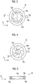
- Figs. 3 and 4 are top views of the position fixing unit 15.
- the fixing member 15b of the position fixing unit 15 is provided with a stop mechanism 15c.
- the stop mechanism 15c changes the size of the opening 15a of the position fixing unit 15.
- Fig. 3 is a diagram showing a state where the stop mechanism 15c is adjusted so that the diameter of the opening 15a is set to D1.
- Fig. 4 is a diagram showing a state where the stop mechanism 15c is adjusted so that the diameter of the opening 15a is set to D2 (D1>D2).
- the position fixing unit 15 comprises an adjustment knob 15d that is used to adjust the size of the opening 15a formed by the stop mechanism 15c.
- a user operates the adjustment knob 15d according to the size of the convex portion, so that the stop of the stop mechanism 15c is adjusted and the size of the opening 15a is adjusted. It is preferable that the maximum diameter of the opening 15a is adjusted in the range of 1 mm to 10 cm.
- the size of the opening 15a can be changed by the stop mechanism 15c in this embodiment, but the invention is not limited thereto.
- a plurality of position fixing units 15 of which the sizes of the openings 15a are different from each other may be adapted to be attachable to and detachable from the fixing unit-support member 16.
- the position fixing unit 15 comprises a silicone resin member 15e.
- Fig. 5 is a cross-sectional view of the position fixing unit 15 shown in Fig. 3 taken along line B-B.
- the stop mechanism 15c is not shown in Fig. 5 .
- the silicone resin member 15e is provided on the lower surface of the fixing member 15b, that is, the surface of the fixing member 15b against which the periphery of the convex portion is to be pressed.
- the silicone resin member 15e is provided to allow the position fixing unit 15 to be in close contact with the skin of the periphery of the convex portion and to prevent damage to the skin of the periphery of the convex portion.
- the silicone resin member 15e has the same shape as the fixing member 15b, and is provided along the fixing member 15b.
- the silicone resin member 15e is not limited to one type, and it is preferable that a plurality of silicone resin members 15e having different stiffness are adapted to be interchangeable.
- a mounting portion may be provided on, for example, the lower surface of the fixing member 15b and a plurality of silicone resin members 15e having different stiffness may be adapted to be capable of being mounted on the mounting portion while being interchanged.
- an adhesive layer to which the silicone resin member 15e can attachably and detachably adhere may be formed as the mounting portion, or a frame body to which the silicone resin member 15e can be attachably and detachably fitted may be formed as the mounting portion.
- a silicone resin member 15e having low stiffness can be used in a case where the skin of a mouse is soft, and a silicone resin member 15e having high stiffness can be used in a case where the skin of the mouse is hard. Therefore, damage to the skin of the mouse can be prevented.
- Fig. 6 is a diagram showing a state where the silicone resin member 15e is pressed against a skin M of a mouse and a convex portion MX is disposed in the opening 15a. The stop mechanism 15c is not shown even in Fig. 6 .
- Silicone resin members 15e having different stiffness are adapted to be interchangeable in this embodiment, so that the stiffness of the position fixing unit 15 can be changed.
- the invention is not limited thereto, and, for example, a plurality of position fixing units 15 including fixing members 15b having different stiffness may be adapted to be attachable to and detachable from the fixing unit-support member 16.
- the light detection unit-support part 17 is connected to the light detection unit 11 and the fixing base 19 and supports the light detection unit 11 with respect to the fixing base 19.
- the light detection unit-support part 17 comprises a first support part 17a of one end is connected to the light detection unit 11, a rotational moving part 18 to which the other end of the first support part 17a is connected, and a second support part 17b of which one end is connected to the rotational moving part 18.
- the rotational moving part 18 is adapted to allow the first support part 17a to be movable rotationally about a rotational movement axis AX in the direction of an arrow A. Accordingly, the height of the light detection unit 11 can be adjusted.
- the fixing base 19 having the shape of a rectangular parallelepiped is connected to the other end of the second support part 17b.
- the measurement result processing device 20 is formed of a computer that comprises a central processing unit (CPU), a memory, and the like, and controls the entire bioinstrumentation system.
- the measurement result processing device 20 is a device where a measurement program is installed on a computer, and the respective components of the measurement result processing device 20 function in a case where the CPU operates the program.
- the measurement program is recorded in recording mediums, such as a digital versatile disc (DVD) and a compact disc read only memory (CD-ROM), and is distributed, and is installed on the computer from the recording medium.
- the measurement program is stored in a storage of a server computer, which is connected to a network, or a network-attached storage in a state where a user can access the measurement program from the outside; and is downloaded and installed on the computer on demand.
- the measurement result processing device 20 comprises a measurement result calculation unit 21 and a display control unit 22.
- the measurement result calculation unit 21 acquires a detection signal output from the detection unit 14 of the measuring unit body 10, and calculates the morphological information of the convex portion, which is formed on the skin of the animal, on the basis of the detection signal.
- the measurement result calculation unit 21 calculates the position of each scanning point of the convex portion by using, for example, a triangulation method or the like on the basis of the detection signal output from the detection unit 14. Then, the measurement result calculation unit 21 calculates the height of each scanning point of the convex portion on the basis of the position of each scanning point of the convex portion.
- the measurement result calculation unit 21 sets a base level that is the reference of a height.
- the measurement result calculation unit 21 of this embodiment sets the lower surface of the fixing member 15b, that is, the surface of the fixing member 15b against which the periphery of the convex portion is to be pressed, as the base level.
- Fig. 7 is a diagram showing a three-dimensional model MD of the fixing member 15b and the base level BL set on the three-dimensional model.
- the three-dimensional model MD of the fixing member 15b shown in Fig. 7 is preset in the measurement result calculation unit 21 together with the three-dimensional position information thereof.
- the position information of the three-dimensional model MD of the fixing member 15b is updated. Since the lower surface of the fixing member 15b is set as the base level as described above, the base level can be always set to the same position even in a case where, for example, a tumor is measured plural times in time series.
- the lower surface of the fixing member 15b is set as the base level in this embodiment, but the invention is not limited thereto.
- the upper surface of the fixing member 15b or the middle plane of the fixing member 15b in the Z direction may be set as the base level.
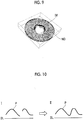
- Fig. 9 is a diagram showing the three-dimensional model MD of the above-mentioned fixing member 15b and a three-dimensional image IM of the convex portion that is calculated using the height H of each scanning point of the convex portion.
- the three-dimensional image IM of the convex portion is generated in a case where a polygonal surface is set using, for example, the height H of each scanning point of the convex portion.
- Various methods which are publicly known, can be used as a method of generating the three-dimensional image IM of the convex portion.
- the measurement result calculation unit 21 not only generates three-dimensional images as the morphological information of the convex portion but also calculates the volume, area, length, and the like of the convex portion using the three-dimensional images.
- the maximum area of the area of the cut surface of the convex portion in a plane orthogonal to the Z direction may be calculated as the area of the convex portion.
- the maximum length of the above-mentioned cut surface may be calculated as the length of the convex portion.
- the three-dimensional images of the convex portion, which are generated by the measurement result calculation unit 21, and the volume and the like of the convex portion are output to the display control unit 22.
- the display control unit 22 allows the display device 2 to display morphological information, such as the three-dimensional images and the volume of the convex portion. Morphological information, such as the volume of the convex portion, may be displayed as numerical data, or may be displayed as a graph.
- Fig. 11 is a diagram showing an example of a display method in a case where pieces of the information about the morphology of a convex portion of a mouse are measured in time series. It is preferable that the display control unit 22 acquires the morphological information of the convex portion measured in time series and displays the morphological information on the same screen or a plurality of screens so that pieces of the morphological information are arranged in time series.
- Fig. 11 is a diagram showing an example where results measured eight times in time series from a first measurement performed on November 13, 2015 are displayed on the same screen. In Fig. 11 , the three-dimensional images of the convex portion and the graph of the volume of the convex portion are displayed as morphological information.
- the three-dimensional images of the convex portion are to be displayed so as to be arranged in time series as shown in Fig. 11 , it is preferable that the three-dimensional images are displayed so as to be aligned in a preset direction of the convex portion.
- the direction of a major axis and the direction of a minor axis in a case where the convex portion is approximated to an ellipse, can be set as the preset direction.
- the direction of the maximum length of each convex portion may be set as the preset direction.
- the display directions of the plurality of three-dimensional images of the convex portions may be adapted to finely adjustable according to inputs received from an input device (not shown), such as a mouse or a keyboard. Accordingly, it is possible to finely adjust the display directions of the three-dimensional images of the convex portions so that a user easily compares and observes the three-dimensional images.
- pieces of the morphological information of the convex portion measured in time series are to be simultaneously displayed on the same screen so as to be arranged as shown in Fig. 11 , it is preferable that pieces of the morphological information of the convex portion measured under different conditions are further displayed on the same screen or a plurality of screens so as to be arranged in time series.
- the morphological information of the convex portion measured in time series in each of different periods of time may be displayed on the same screen or a plurality of screens so as to be arranged in time series.
- a plurality of pieces of morphological information, which are obtained in a case where a drug, such as an anticancer drug, is put into the convex portion (tumor) and the convex portion is measured in time series and a plurality of pieces of morphological information, which are obtained in a case where a drug is not put into the convex portion and the convex portion is measured in time series, may be displayed on the same screen or a plurality of screens.
- different kinds of drugs may be put into the convex portion and different amounts of drug may be put into the convex portion.
- the morphological information of the convex portion measured under different conditions is displayed on the same screen or a plurality of screens as described above, information about the effect and the like of an anticancer drug can be obtained.
- the convex portion such as a tumor
- the convex portion is irradiated with light and reflected light reflected from the convex portion is detected to measure the morphological information of the convex portion.
- light to be detected is not limited to the reflected light, and, for example, fluorescence emitted from the convex portion due to the irradiation of the convex portion with light may be detected to measure the morphological information of the convex portion.
Landscapes
- Health & Medical Sciences (AREA)
- Life Sciences & Earth Sciences (AREA)
- Physics & Mathematics (AREA)
- Molecular Biology (AREA)
- Animal Behavior & Ethology (AREA)
- Veterinary Medicine (AREA)
- Biophysics (AREA)
- Pathology (AREA)
- Engineering & Computer Science (AREA)
- Biomedical Technology (AREA)
- Heart & Thoracic Surgery (AREA)
- Medical Informatics (AREA)
- Public Health (AREA)
- Surgery (AREA)
- General Health & Medical Sciences (AREA)
- General Physics & Mathematics (AREA)
- Oral & Maxillofacial Surgery (AREA)
- Dentistry (AREA)
- Dermatology (AREA)
- Nuclear Medicine, Radiotherapy & Molecular Imaging (AREA)
- Radiology & Medical Imaging (AREA)
- Length Measuring Devices By Optical Means (AREA)
- Measurement Of The Respiration, Hearing Ability, Form, And Blood Characteristics Of Living Organisms (AREA)
- Investigating Or Analysing Materials By Optical Means (AREA)
Abstract
Description
- The present invention relates to a measuring device that measures the morphology of a convex portion, such as a tumor formed on the skin of, for example, an animal.
- In the related art, for example, a method including forming a tumor on the skin of a small animal, such as a mouse, putting a candidate compound into the tumor, and observing a reduction in the size of the tumor to evaluate a drug effect has been performed in the research and development of, for example, an anticancer drug.
- In a case where a reduction in the size of the tumor is to be observed as described above, the size of the tumor has been measured using, for example, a measuring equipment, such as a vernier caliper. However, it is difficult to fix the measuring equipment, such as a vernier caliper, to the tumor since the skin of the mouse is soft. Further, a method of fixing the vernier caliper to the tumor by an operator varies. For this reason, it is difficult to obtain objective measurement results.
- A so-called three-dimensional scanner, which irradiates a tumor with light and measures the three-dimensional morphology of the tumor by detecting reflected light reflected from the tumor, is proposed in, for example,
US2005/0084176A . - However, the three-dimensional scanner disclosed in
US2005/0084176A also has a problem that the same measurement results are not obtained according to a method of disposing a mouse and the range of the tumor to be irradiated with light even though the same tumor is measured. - Further, in a case where a reduction in the size of the tumor is to be evaluated, the size of the tumor needs to be measured plural times in time series. However, since a method of disposing the mouse is performed or a range to be irradiated with light is set whenever the size of the tumor is measured, sufficient measurement accuracy cannot be obtained.
- The invention has been made in consideration of the above-mentioned problem, and an object of the invention is to provide a measuring device that can measure the morphology of a convex portion, such as a tumor formed on the skin of an animal, with high accuracy.
- A measuring device of the invention comprises a measuring unit that measures the morphology of a convex portion, and a position fixing unit that includes an opening in which the convex portion is to be disposed and a fixing member which includes the opening at a center thereof and against which a periphery of the convex portion is to be pressed. A size of the opening of the position fixing unit is capable of being changed.
- Further, in the measuring device of the invention, the fixing member may be provided with a stop mechanism that changes the size of the opening.
- Furthermore, in the measuring device of the invention, it is preferable that the fixing member has a shape of a ring.
- Moreover, in the measuring device of the invention, it is preferable that stiffness of at least a portion of the fixing member against which the periphery of the convex portion is to be pressed is capable of being changed.
- Further, in the measuring device of the invention, it is preferable that a resin member is provided on the portion of the fixing member against which the periphery of the convex portion is to be pressed and a plurality of the resin members having different stiffness are adapted to be interchangeable.
- Furthermore, in the measuring device of the invention, it is preferable that a maximum length of the opening of the position fixing unit is in the range of 1 mm to 10 cm.
- Moreover, in the measuring device of the invention, the measuring unit may set a base level on the basis of the fixing member and measure the morphology of the convex portion using the base level.
- Further, in the measuring device of the invention, the measuring unit may set a surface of the fixing member, against which the periphery of the convex portion is to be pressed, as the base level.
- Furthermore, the measuring device of the invention may further comprise a display control unit that acquires information about the morphology of the convex portion measured in time series by the measuring unit and displays the information about the morphology on the same screen or a plurality of screens so that the information about the morphologies are arranged in time series.
- Moreover, in the measuring device of the invention, the display control unit may display numerical data as the information about the morphology of the convex portion so that the numerical data are arranged in time series.
- Further, in the measuring device of the invention, the display control unit may display three-dimensional images of the convex portion as the information about the morphology of the convex portion so that the three-dimensional images of the convex portion are arranged in time series.
- Furthermore, in the measuring device of the invention, the display control unit may display the three-dimensional images of the convex portion so that the three-dimensional images are aligned in a preset direction of the convex portion, in a case where the display control unit is to display the three-dimensional images of the convex portion so that the three-dimensional images of the convex portion are arranged in time series.
- Moreover, in the measuring device of the invention, the display control unit may display information about the morphology of the convex portion, which are measured under different conditions, on the same screen or a plurality of screens so that the information about the morphologies of the convex portion are arranged in time series.
- Further, in the measuring device of the invention, the measuring unit may irradiate the convex portion with light and measure the morphology of the convex portion by detecting reflected light reflected from the convex portion or light emitted from the convex portion.
- Furthermore, in the measuring device of the invention, the measuring unit may scan the convex portion with laser light and detect reflected light reflected from the convex portion or light emitted from the convex portion due to scanning using the laser light.
- According to the measuring device of the invention, there is provided the position fixing unit that includes an opening in which the convex portion is to be disposed and a fixing member which includes the opening at a center thereof and against which the periphery of the convex portion is to be pressed. Accordingly, even in a case where an object to be measured is a soft mouse or the like, the disposition of the convex portion, such as a tumor, can be stabilized. Further, since the size of the opening of the position fixing unit is capable of being changed, it is possible to stably measure the tumor by changing the size of the opening according to the size of the tumor even in a case where a tumor of which the size is changed with the lapse of time is to be measured. Accordingly, it is possible to measure the morphology of the convex portion with higher accuracy than in the related art.
-
-
Fig. 1 is a block diagram showing the schematic configuration of a bioinstrumentation system that uses an embodiment of a measuring device of the invention. -
Fig. 2 is a diagram showing the schematic configuration of a measuring unit body shown inFig. 1 . -
Fig. 3 is a top view of a position fixing unit. -
Fig. 4 is a top view of the position fixing unit. -
Fig. 5 is a side cross-sectional view of the position fixing unit. -
Fig. 6 is a side cross-sectional view showing a state where a convex portion is disposed in an opening of the position fixing unit. -
Fig. 7 is a diagram showing a three-dimensional model MD of a fixing member and a base level BL set on the three-dimensional model. -
Fig. 8 is a diagram illustrating a method of acquiring the height of each scanning point of the convex portion. -
Fig. 9 is a diagram showing the three-dimensional model MD of the fixing member and a three-dimensional image IM of the convex portion. -
Fig. 10 is a diagram illustrating the interpolation of a measurement result. -
Fig. 11 is a diagram showing an example of a display method in a case where pieces of the morphological information of a convex portion of a mouse are measured in time series. - A bioinstrumentation system, which uses an embodiment of a measuring device of the invention, will be described in detail below with reference to the drawings.
Fig. 1 is a block diagram showing the schematic configuration of the bioinstrumentation system of this embodiment. The bioinstrumentation system of this embodiment measures the morphology of, for example, a convex portion, such as a tumor formed on the skin of an animal, and allows a display unit to display information about the morphology. - As shown in
Fig. 1 , the bioinstrumentation system of this embodiment comprises ameasuring device 1 and a display device 2. Themeasuring device 1 comprises ameasuring unit body 10 and a measurementresult processing device 20.Fig. 2 is a diagram showing the specific configuration of themeasuring unit body 10. In this embodiment, themeasuring unit body 10 and a measurementresult calculation unit 21 to be described later form a measuring unit of the invention. - As shown in
Fig. 2 , themeasuring unit body 10 comprises alight detection unit 11, aposition fixing unit 15, a light detection unit-support part 17, and afixing base 19. - The
light detection unit 11 comprises alight source unit 12, a condensingoptical system 13, and adetection unit 14. Thelight source unit 12, the condensingoptical system 13, and thedetection unit 14 are received in ahousing 11a. Thehousing 11a is formed of a member that blocks light, or the like. A through-hole 11b through which laser light L1 emitted from thelight source unit 12 passes and a through-hole 11c through which reflected light L2 reflected from a convex portion as an object to be measured passes are formed in thehousing 11a. - The
light source unit 12 comprises a laser light source and a scanning mechanism that applies laser light L1 emitted from the laser light source. The convex portion fixed to theposition fixing unit 15 is irradiated with laser light L1 emitted from thelight source unit 12. Specifically, laser light L1 emitted from the laser light source is applied by the scanning mechanism, so that the surface of the convex portion is two-dimensionally scanned with laser light L1. A publicly known mechanism, which includes a mirror, an actuator, and the like, can be used as the scanning mechanism. A method of scanning the surface of the convex portion in directions orthogonal to each other with spot light or a method of scanning the surface of the convex portion in one direction with linear laser light L1 may be used as a method of two-dimensionally scanning the surface of the convex portion with laser light L1. In terms of measurement time, it is preferable that the surface of the convex portion is scanned in one direction with linear laser light L1. Further, the surface of the convex portion is scanned with laser light L1 in an X-Y plane shown inFig. 2 . A Z direction shown inFig. 2 is a vertical direction, and the directions of an X-Y plane are horizontal directions. - The condensing
optical system 13 condenses reflected light L2, which is reflected from the convex portion, on thedetection unit 14. The condensingoptical system 13 includes an optical element, such as a condensing lens. - The
detection unit 14 detects the intensity of reflected light L2 that is reflected from the convex portion. For example, a charge-coupled device (CCD) image sensor, a complementary metal-oxide semiconductor (CMOS) image sensor, a line sensor, and the like can be used as thedetection unit 14. - The
position fixing unit 15 fixes the position of the convex portion as an object to be measured that is formed on the skin of an animal. Specifically, theposition fixing unit 15 comprises anopening 15a in which the convex portion is to be disposed, and a fixingmember 15b which includes theopening 15a at the center thereof and against which the periphery of the convex portion is to be pressed. The fixingmember 15b is made of a black resin absorbing light, or the like, and is formed in the shape of a ring. The shape of a ring does not necessarily need to be a circular shape, and anopening 15a having a polygonal shape, such as a triangular shape and a quadrangular shape, may be formed. - The
position fixing unit 15 is connected to thehousing 11a of the measuringunit body 10 through a fixing unit-support member 16. One end of the fixing unit-support member 16 is connected to theposition fixing unit 15, and the other end thereof is connected to thehousing 11a. The length of the fixing unit-support member 16 in the vertical direction (the Z direction shown inFig. 2 ) may be fixed, but it is more preferable that the length is variable. -
Figs. 3 and 4 are top views of theposition fixing unit 15. As shown inFigs. 3 and 4 , the fixingmember 15b of theposition fixing unit 15 is provided with astop mechanism 15c. Thestop mechanism 15c changes the size of theopening 15a of theposition fixing unit 15.Fig. 3 is a diagram showing a state where thestop mechanism 15c is adjusted so that the diameter of theopening 15a is set to D1.Fig. 4 is a diagram showing a state where thestop mechanism 15c is adjusted so that the diameter of theopening 15a is set to D2 (D1>D2). Theposition fixing unit 15 comprises anadjustment knob 15d that is used to adjust the size of theopening 15a formed by thestop mechanism 15c. A user operates theadjustment knob 15d according to the size of the convex portion, so that the stop of thestop mechanism 15c is adjusted and the size of theopening 15a is adjusted. It is preferable that the maximum diameter of theopening 15a is adjusted in the range of 1 mm to 10 cm. - The size of the
opening 15a can be changed by thestop mechanism 15c in this embodiment, but the invention is not limited thereto. For example, a plurality ofposition fixing units 15 of which the sizes of theopenings 15a are different from each other may be adapted to be attachable to and detachable from the fixing unit-support member 16. - Further, as shown in
Fig. 5 , theposition fixing unit 15 comprises asilicone resin member 15e.Fig. 5 is a cross-sectional view of theposition fixing unit 15 shown inFig. 3 taken along line B-B. Thestop mechanism 15c is not shown inFig. 5 . Thesilicone resin member 15e is provided on the lower surface of the fixingmember 15b, that is, the surface of the fixingmember 15b against which the periphery of the convex portion is to be pressed. Thesilicone resin member 15e is provided to allow theposition fixing unit 15 to be in close contact with the skin of the periphery of the convex portion and to prevent damage to the skin of the periphery of the convex portion. Thesilicone resin member 15e has the same shape as the fixingmember 15b, and is provided along the fixingmember 15b. - The
silicone resin member 15e is not limited to one type, and it is preferable that a plurality ofsilicone resin members 15e having different stiffness are adapted to be interchangeable. Specifically, a mounting portion may be provided on, for example, the lower surface of the fixingmember 15b and a plurality ofsilicone resin members 15e having different stiffness may be adapted to be capable of being mounted on the mounting portion while being interchanged. For example, an adhesive layer to which thesilicone resin member 15e can attachably and detachably adhere may be formed as the mounting portion, or a frame body to which thesilicone resin member 15e can be attachably and detachably fitted may be formed as the mounting portion. Accordingly, for example, asilicone resin member 15e having low stiffness can be used in a case where the skin of a mouse is soft, and asilicone resin member 15e having high stiffness can be used in a case where the skin of the mouse is hard. Therefore, damage to the skin of the mouse can be prevented.Fig. 6 is a diagram showing a state where thesilicone resin member 15e is pressed against a skin M of a mouse and a convex portion MX is disposed in theopening 15a. Thestop mechanism 15c is not shown even inFig. 6 . -
Silicone resin members 15e having different stiffness are adapted to be interchangeable in this embodiment, so that the stiffness of theposition fixing unit 15 can be changed. However, the invention is not limited thereto, and, for example, a plurality ofposition fixing units 15 including fixingmembers 15b having different stiffness may be adapted to be attachable to and detachable from the fixing unit-support member 16. - Returning to
Fig. 2 , the light detection unit-support part 17 is connected to thelight detection unit 11 and the fixingbase 19 and supports thelight detection unit 11 with respect to the fixingbase 19. Specifically, the light detection unit-support part 17 comprises afirst support part 17a of one end is connected to thelight detection unit 11, a rotational movingpart 18 to which the other end of thefirst support part 17a is connected, and asecond support part 17b of which one end is connected to the rotational movingpart 18. The rotational movingpart 18 is adapted to allow thefirst support part 17a to be movable rotationally about a rotational movement axis AX in the direction of an arrow A. Accordingly, the height of thelight detection unit 11 can be adjusted. The fixingbase 19 having the shape of a rectangular parallelepiped is connected to the other end of thesecond support part 17b. - Returning to
Fig. 1 , the measurementresult processing device 20 will be described. The measurementresult processing device 20 is formed of a computer that comprises a central processing unit (CPU), a memory, and the like, and controls the entire bioinstrumentation system. The measurementresult processing device 20 is a device where a measurement program is installed on a computer, and the respective components of the measurementresult processing device 20 function in a case where the CPU operates the program. The measurement program is recorded in recording mediums, such as a digital versatile disc (DVD) and a compact disc read only memory (CD-ROM), and is distributed, and is installed on the computer from the recording medium. Alternatively, the measurement program is stored in a storage of a server computer, which is connected to a network, or a network-attached storage in a state where a user can access the measurement program from the outside; and is downloaded and installed on the computer on demand. - As shown in
Fig. 1 , the measurementresult processing device 20 comprises a measurementresult calculation unit 21 and adisplay control unit 22. The measurementresult calculation unit 21 acquires a detection signal output from thedetection unit 14 of the measuringunit body 10, and calculates the morphological information of the convex portion, which is formed on the skin of the animal, on the basis of the detection signal. - Specifically, the measurement
result calculation unit 21 calculates the position of each scanning point of the convex portion by using, for example, a triangulation method or the like on the basis of the detection signal output from thedetection unit 14. Then, the measurementresult calculation unit 21 calculates the height of each scanning point of the convex portion on the basis of the position of each scanning point of the convex portion. - Here, in a case where the measurement
result calculation unit 21 calculates the height of each scanning point of the convex portion, the measurementresult calculation unit 21 sets a base level that is the reference of a height. The measurementresult calculation unit 21 of this embodiment sets the lower surface of the fixingmember 15b, that is, the surface of the fixingmember 15b against which the periphery of the convex portion is to be pressed, as the base level.Fig. 7 is a diagram showing a three-dimensional model MD of the fixingmember 15b and the base level BL set on the three-dimensional model. The three-dimensional model MD of the fixingmember 15b shown inFig. 7 is preset in the measurementresult calculation unit 21 together with the three-dimensional position information thereof. For example, whenever the position of the lower surface of the fixingmember 15b is changed due to the exchange of theposition fixing unit 15 or a change in the length of the fixing unit-support member 16 in the Z direction, the position information of the three-dimensional model MD of the fixingmember 15b is updated. Since the lower surface of the fixingmember 15b is set as the base level as described above, the base level can be always set to the same position even in a case where, for example, a tumor is measured plural times in time series. The lower surface of the fixingmember 15b is set as the base level in this embodiment, but the invention is not limited thereto. For example, the upper surface of the fixingmember 15b or the middle plane of the fixingmember 15b in the Z direction may be set as the base level. - Then, the measurement
result calculation unit 21 acquires the height H of each scanning point of the convex portion by calculating a difference between the position P of each scanning point of the convex portion and the base level BL as shown inFig. 8 .Fig. 9 is a diagram showing the three-dimensional model MD of the above-mentionedfixing member 15b and a three-dimensional image IM of the convex portion that is calculated using the height H of each scanning point of the convex portion. The three-dimensional image IM of the convex portion is generated in a case where a polygonal surface is set using, for example, the height H of each scanning point of the convex portion. Various methods, which are publicly known, can be used as a method of generating the three-dimensional image IM of the convex portion. - For example, in a case where a tumor of a mouse has one convex portion, a case where a tumor of a mouse has an uneven shape having two convex portions, and the like, there is a case where positions P of scanning points of a part of a concave portion cannot be measured since a part of the concave portion cannot be irradiated with laser light L1 as shown in (I) of
Fig. 10 . In this case, as shown in (II) ofFig. 10 , the positions P of the scanning points, which cannot be measured, may be acquired by interpolation calculation performed using the measured positions P of scanning points around the concave portion. - Further, the measurement
result calculation unit 21 not only generates three-dimensional images as the morphological information of the convex portion but also calculates the volume, area, length, and the like of the convex portion using the three-dimensional images. For example, the maximum area of the area of the cut surface of the convex portion in a plane orthogonal to the Z direction may be calculated as the area of the convex portion. Furthermore, for example, the maximum length of the above-mentioned cut surface may be calculated as the length of the convex portion. The three-dimensional images of the convex portion, which are generated by the measurementresult calculation unit 21, and the volume and the like of the convex portion are output to thedisplay control unit 22. - The
display control unit 22 allows the display device 2 to display morphological information, such as the three-dimensional images and the volume of the convex portion. Morphological information, such as the volume of the convex portion, may be displayed as numerical data, or may be displayed as a graph. -
Fig. 11 is a diagram showing an example of a display method in a case where pieces of the information about the morphology of a convex portion of a mouse are measured in time series. It is preferable that thedisplay control unit 22 acquires the morphological information of the convex portion measured in time series and displays the morphological information on the same screen or a plurality of screens so that pieces of the morphological information are arranged in time series.Fig. 11 is a diagram showing an example where results measured eight times in time series from a first measurement performed on November 13, 2015 are displayed on the same screen. InFig. 11 , the three-dimensional images of the convex portion and the graph of the volume of the convex portion are displayed as morphological information. Only measurement results measured five times are displayed in regard to the three-dimensional images of the convex portion, but the other three measurement results measured three times can be displayed in a case in which a scroll bar displayed below the display columns for a three-dimensional image is operated to the right side. - Further, in a case where the three-dimensional images of the convex portion are to be displayed so as to be arranged in time series as shown in
Fig. 11 , it is preferable that the three-dimensional images are displayed so as to be aligned in a preset direction of the convex portion. For example, the direction of a major axis and the direction of a minor axis, in a case where the convex portion is approximated to an ellipse, can be set as the preset direction. Alternatively, the direction of the maximum length of each convex portion may be set as the preset direction. In a case where the display directions of the plurality of three-dimensional images of the convex portions are aligned as described above, it is possible to easily compare and observe the three-dimensional images. The display directions of the three-dimensional images of the convex portions may be adapted to finely adjustable according to inputs received from an input device (not shown), such as a mouse or a keyboard. Accordingly, it is possible to finely adjust the display directions of the three-dimensional images of the convex portions so that a user easily compares and observes the three-dimensional images. - Further, in a case where pieces of the morphological information of the convex portion measured in time series are to be simultaneously displayed on the same screen so as to be arranged as shown in
Fig. 11 , it is preferable that pieces of the morphological information of the convex portion measured under different conditions are further displayed on the same screen or a plurality of screens so as to be arranged in time series. Specifically, for example, the morphological information of the convex portion measured in time series in each of different periods of time may be displayed on the same screen or a plurality of screens so as to be arranged in time series. Alternatively, a plurality of pieces of morphological information, which are obtained in a case where a drug, such as an anticancer drug, is put into the convex portion (tumor) and the convex portion is measured in time series, and a plurality of pieces of morphological information, which are obtained in a case where a drug is not put into the convex portion and the convex portion is measured in time series, may be displayed on the same screen or a plurality of screens. Further, as the different conditions, different kinds of drugs may be put into the convex portion and different amounts of drug may be put into the convex portion. In a case where the morphological information of the convex portion measured under different conditions is displayed on the same screen or a plurality of screens as described above, information about the effect and the like of an anticancer drug can be obtained. - In the embodiment, the convex portion, such as a tumor, is irradiated with light and reflected light reflected from the convex portion is detected to measure the morphological information of the convex portion. However, light to be detected is not limited to the reflected light, and, for example, fluorescence emitted from the convex portion due to the irradiation of the convex portion with light may be detected to measure the morphological information of the convex portion.
-
- 1: measuring device
- 2: display device
- 10: measuring unit body
- 11: light detection unit
- 11a: housing
- 11b: through-hole
- 11c: through-hole
- 12: light source unit
- 13: condensing optical system
- 14: detection unit
- 15: position fixing unit
- 15a: opening
- 15b: fixing member
- 15c: stop mechanism
- 15e: silicone resin member
- 15e: adjustment knob
- 16: fixing unit-support member
- 17: light detection unit-support part
- 17a: first support part
- 17b: second support part
- 18: rotational moving part
- 19: fixing base
- 20: measurement result processing device
- 21: measurement result calculation unit
- 22: display control unit
- AX: rotational movement axis
- BL: base level
- IM: three-dimensional image
- L1: laser light
- L2: reflected light
- M: skin
- MD: three-dimensional model
- MX: convex portion
- P: position of each scanning point of convex portion
Claims (15)
- A measuring device comprising:a measuring unit that measures the morphology of a convex portion; anda position fixing unit that includes an opening in which the convex portion is to be disposed and a fixing member which includes the opening at a center thereof and against which a periphery of the convex portion is to be pressed,wherein a size of the opening of the position fixing unit is capable of being changed.
- The measuring device according to claim 1,
wherein the fixing member is provided with a stop mechanism that changes the size of the opening. - The measuring device according to claim 1 or 2,
wherein the fixing member has a shape of a ring. - The measuring device according to any one of claims 1 to 3,
wherein stiffness of at least a portion of the fixing member against which the periphery of the convex portion is to be pressed is capable of being changed. - The measuring device according to claim 4,
wherein a resin member is provided on the portion of the fixing member against which the periphery of the convex portion is to be pressed, and a plurality of the resin members having different stiffness are adapted to be interchangeable. - The measuring device according to any one of claims 1 to 5,
wherein a maximum length of the opening of the position fixing unit is in the range of 1 mm to 10 cm. - The measuring device according to any one of claims 1 to 6,
wherein the measuring unit sets a base level on the basis of the fixing member and measures the morphology of the convex portion using the base level. - The measuring device according to claim 7,
wherein the measuring unit sets a surface of the fixing member, against which the periphery of the convex portion is to be pressed, as the base level. - The measuring device according to any one of claims 1 to 8, further comprising:
a display control unit that acquires information about morphology of the convex portion measured in time series by the measuring unit and displays the information about the morphology on the same screen or a plurality of screens so that the information about the morphologies are arranged in time series. - The measuring device according to claim 9,
wherein the display control unit displays numerical data as the information about the morphology of the convex portion so that the numerical data are arranged in time series. - The measuring device according to claim 9 or 10,
wherein the display control unit displays three-dimensional images of the convex portion as the information about the morphology of the convex portion so that the three-dimensional images of the convex portion are arranged in time series. - The measuring device according to claim 11,
wherein the display control unit displays the three-dimensional images of the convex portion so that the three-dimensional images are aligned in a preset direction of the convex portion, in a case where the display control unit is to display the three-dimensional images of the convex portion so that the three-dimensional images of the convex portion are arranged in time series. - The measuring device according to any one of claims 9 to 12,
wherein the display control unit displays information about the morphology of the convex portion, which are measured under different conditions, on the same screen or a plurality of screens so that the information about the morphologies of the convex portion are arranged in time series. - The measuring device according to any one of claims 1 to 13,
wherein the measuring unit irradiates the convex portion with light and measures the morphology of the convex portion by detecting reflected light reflected from the convex portion or light emitted from the convex portion. - The measuring device according to claim 14,
wherein the measuring unit scans the convex portion with laser light and detects reflected light reflected from the convex portion or light emitted from the convex portion due to scanning using the laser light.
Applications Claiming Priority (2)
| Application Number | Priority Date | Filing Date | Title |
|---|---|---|---|
| JP2016183781A JP6570497B2 (en) | 2016-09-21 | 2016-09-21 | Measuring device |
| PCT/JP2017/033340 WO2018056183A1 (en) | 2016-09-21 | 2017-09-14 | Measurement device |
Publications (3)
| Publication Number | Publication Date |
|---|---|
| EP3517889A1 true EP3517889A1 (en) | 2019-07-31 |
| EP3517889A4 EP3517889A4 (en) | 2019-09-25 |
| EP3517889B1 EP3517889B1 (en) | 2022-01-26 |
Family
ID=61690450
Family Applications (1)
| Application Number | Title | Priority Date | Filing Date |
|---|---|---|---|
| EP17852956.6A Active EP3517889B1 (en) | 2016-09-21 | 2017-09-14 | Measurement device |
Country Status (4)
| Country | Link |
|---|---|
| US (1) | US11371834B2 (en) |
| EP (1) | EP3517889B1 (en) |
| JP (1) | JP6570497B2 (en) |
| WO (1) | WO2018056183A1 (en) |
Family Cites Families (11)
| Publication number | Priority date | Publication date | Assignee | Title |
|---|---|---|---|---|
| WO2005033620A2 (en) | 2003-09-12 | 2005-04-14 | Biopticon Corporation | Methods and systems for measuring the size and volume of features on live tissue |
| EP1736816B1 (en) * | 2004-03-31 | 2012-06-13 | Topcon Corporation | Device for installing suction jig for eyeglass lens and method for determining suction jig installation position |
| US20070247639A1 (en) * | 2004-05-10 | 2007-10-25 | Koninklijke Philips Electronics, N.V. | Device and Method for Optical Precision Measurement |
| US7532320B2 (en) * | 2004-06-30 | 2009-05-12 | Chemimage Corporation | Multimodal method for identifying hazardous agents |
| JP2007229320A (en) * | 2006-03-03 | 2007-09-13 | Nippon Telegr & Teleph Corp <Ntt> | Component concentration measuring device |
| US10376150B2 (en) * | 2011-09-30 | 2019-08-13 | The Trustees Of Columbia University In The City Of New York | Interfacing systems, devices, and methods for optical imaging |
| JP5745435B2 (en) * | 2012-02-01 | 2015-07-08 | 東芝プラントシステム株式会社 | 3D data processing apparatus, 3D data processing program, and 3D data processing method |
| DE102012205311B4 (en) * | 2012-03-30 | 2013-10-17 | Anton Paar Gmbh | Optical device, in particular polarimeter, for detecting inhomogeneities in a sample |
| EP2992310B1 (en) * | 2013-05-02 | 2019-07-31 | Carl Zeiss Vision International GmbH | Method and system for determining the spatial structure of an object |
| JP2014240793A (en) * | 2013-06-12 | 2014-12-25 | 花王株式会社 | Method for measuring skin surface shape change and skin surface shape measurement device |
| DE102014007203A1 (en) * | 2014-05-19 | 2015-11-19 | Luphos Gmbh | Device and method for geometric measurement of an object |
-
2016
- 2016-09-21 JP JP2016183781A patent/JP6570497B2/en active Active
-
2017
- 2017-09-14 WO PCT/JP2017/033340 patent/WO2018056183A1/en not_active Ceased
- 2017-09-14 EP EP17852956.6A patent/EP3517889B1/en active Active
-
2019
- 2019-03-20 US US16/359,289 patent/US11371834B2/en active Active
Also Published As
| Publication number | Publication date |
|---|---|
| EP3517889B1 (en) | 2022-01-26 |
| EP3517889A4 (en) | 2019-09-25 |
| US11371834B2 (en) | 2022-06-28 |
| WO2018056183A1 (en) | 2018-03-29 |
| JP6570497B2 (en) | 2019-09-04 |
| JP2018048875A (en) | 2018-03-29 |
| US20190219386A1 (en) | 2019-07-18 |
Similar Documents
| Publication | Publication Date | Title |
|---|---|---|
| US10094916B1 (en) | LIDAR optics alignment systems and methods | |
| JP6128902B2 (en) | Shape measuring device | |
| RU2653771C2 (en) | Two bodies misalignment device and determination method | |
| JP2020106841A (en) | System and method for calibrating variable focal length lens system by using calibration object with planar tilted pattern surface | |
| US8913247B2 (en) | Device and method for interferometric vibration measurement of an object | |
| CN110353721B (en) | Collimator for adjusting X-ray source | |
| EP2195641B1 (en) | An apparatus and method for observing the surface of a sample | |
| KR101900895B1 (en) | Method and device for alignment of an optical imaging system | |
| JP6758765B2 (en) | Measurement method and measurement program | |
| US20140071438A1 (en) | Method and apparatus for image scanning | |
| KR102073503B1 (en) | Microscopy and Observation Method | |
| JP2012225701A (en) | Shape measuring device | |
| JP6288280B2 (en) | Surface shape measuring device | |
| Jütte et al. | Registration of polarimetric images for in vivo skin diagnostics | |
| KR102149625B1 (en) | Captured image evaluation apparatus and method, and program | |
| US11371834B2 (en) | Measuring device | |
| JP2015108582A (en) | Three-dimensional measurement method and device | |
| CN103536361B (en) | Patient-supporting device and there is the medical imaging apparatus of patient-supporting device | |
| JP2021067774A (en) | Optical device and optical type measuring machine | |
| EP3454006A1 (en) | A method, a system and a computer program for measuring a distance to a target | |
| KR101133562B1 (en) | Profile Measuring Apparatus using The Astigmatic Lens | |
| JP7073149B2 (en) | measuring device | |
| WO2018055762A1 (en) | System for measuring cell state | |
| JP7025124B2 (en) | Image processing method and image processing equipment | |
| KR20230149932A (en) | Apparatus and method for measuring a focal length |
Legal Events
| Date | Code | Title | Description |
|---|---|---|---|
| STAA | Information on the status of an ep patent application or granted ep patent |
Free format text: STATUS: THE INTERNATIONAL PUBLICATION HAS BEEN MADE |
|
| PUAI | Public reference made under article 153(3) epc to a published international application that has entered the european phase |
Free format text: ORIGINAL CODE: 0009012 |
|
| STAA | Information on the status of an ep patent application or granted ep patent |
Free format text: STATUS: REQUEST FOR EXAMINATION WAS MADE |
|
| 17P | Request for examination filed |
Effective date: 20190320 |
|
| AK | Designated contracting states |
Kind code of ref document: A1 Designated state(s): AL AT BE BG CH CY CZ DE DK EE ES FI FR GB GR HR HU IE IS IT LI LT LU LV MC MK MT NL NO PL PT RO RS SE SI SK SM TR |
|
| AX | Request for extension of the european patent |
Extension state: BA ME |
|
| A4 | Supplementary search report drawn up and despatched |
Effective date: 20190826 |
|
| RIC1 | Information provided on ipc code assigned before grant |
Ipc: G01M 11/02 20060101ALI20190820BHEP Ipc: A61B 5/00 20060101ALI20190820BHEP Ipc: A61B 5/107 20060101ALI20190820BHEP Ipc: G01B 11/24 20060101AFI20190820BHEP |
|
| DAV | Request for validation of the european patent (deleted) | ||
| DAX | Request for extension of the european patent (deleted) | ||
| RAP3 | Party data changed (applicant data changed or rights of an application transferred) |
Owner name: FUJIFILM CORPORATION |
|
| GRAP | Despatch of communication of intention to grant a patent |
Free format text: ORIGINAL CODE: EPIDOSNIGR1 |
|
| STAA | Information on the status of an ep patent application or granted ep patent |
Free format text: STATUS: GRANT OF PATENT IS INTENDED |
|
| INTG | Intention to grant announced |
Effective date: 20211015 |
|
| GRAS | Grant fee paid |
Free format text: ORIGINAL CODE: EPIDOSNIGR3 |
|
| GRAA | (expected) grant |
Free format text: ORIGINAL CODE: 0009210 |
|
| STAA | Information on the status of an ep patent application or granted ep patent |
Free format text: STATUS: THE PATENT HAS BEEN GRANTED |
|
| AK | Designated contracting states |
Kind code of ref document: B1 Designated state(s): AL AT BE BG CH CY CZ DE DK EE ES FI FR GB GR HR HU IE IS IT LI LT LU LV MC MK MT NL NO PL PT RO RS SE SI SK SM TR |
|
| REG | Reference to a national code |
Ref country code: GB Ref legal event code: FG4D |
|
| REG | Reference to a national code |
Ref country code: CH Ref legal event code: EP |
|
| REG | Reference to a national code |
Ref country code: AT Ref legal event code: REF Ref document number: 1465603 Country of ref document: AT Kind code of ref document: T Effective date: 20220215 |
|
| REG | Reference to a national code |
Ref country code: IE Ref legal event code: FG4D |
|
| REG | Reference to a national code |
Ref country code: DE Ref legal event code: R096 Ref document number: 602017052892 Country of ref document: DE |
|
| REG | Reference to a national code |
Ref country code: LT Ref legal event code: MG9D |
|
| REG | Reference to a national code |
Ref country code: NL Ref legal event code: MP Effective date: 20220126 |
|
| REG | Reference to a national code |
Ref country code: AT Ref legal event code: MK05 Ref document number: 1465603 Country of ref document: AT Kind code of ref document: T Effective date: 20220126 |
|
| PG25 | Lapsed in a contracting state [announced via postgrant information from national office to epo] |
Ref country code: NL Free format text: LAPSE BECAUSE OF FAILURE TO SUBMIT A TRANSLATION OF THE DESCRIPTION OR TO PAY THE FEE WITHIN THE PRESCRIBED TIME-LIMIT Effective date: 20220126 |
|
| PG25 | Lapsed in a contracting state [announced via postgrant information from national office to epo] |
Ref country code: SE Free format text: LAPSE BECAUSE OF FAILURE TO SUBMIT A TRANSLATION OF THE DESCRIPTION OR TO PAY THE FEE WITHIN THE PRESCRIBED TIME-LIMIT Effective date: 20220126 Ref country code: RS Free format text: LAPSE BECAUSE OF FAILURE TO SUBMIT A TRANSLATION OF THE DESCRIPTION OR TO PAY THE FEE WITHIN THE PRESCRIBED TIME-LIMIT Effective date: 20220126 Ref country code: PT Free format text: LAPSE BECAUSE OF FAILURE TO SUBMIT A TRANSLATION OF THE DESCRIPTION OR TO PAY THE FEE WITHIN THE PRESCRIBED TIME-LIMIT Effective date: 20220526 Ref country code: NO Free format text: LAPSE BECAUSE OF FAILURE TO SUBMIT A TRANSLATION OF THE DESCRIPTION OR TO PAY THE FEE WITHIN THE PRESCRIBED TIME-LIMIT Effective date: 20220426 Ref country code: LT Free format text: LAPSE BECAUSE OF FAILURE TO SUBMIT A TRANSLATION OF THE DESCRIPTION OR TO PAY THE FEE WITHIN THE PRESCRIBED TIME-LIMIT Effective date: 20220126 Ref country code: HR Free format text: LAPSE BECAUSE OF FAILURE TO SUBMIT A TRANSLATION OF THE DESCRIPTION OR TO PAY THE FEE WITHIN THE PRESCRIBED TIME-LIMIT Effective date: 20220126 Ref country code: ES Free format text: LAPSE BECAUSE OF FAILURE TO SUBMIT A TRANSLATION OF THE DESCRIPTION OR TO PAY THE FEE WITHIN THE PRESCRIBED TIME-LIMIT Effective date: 20220126 Ref country code: BG Free format text: LAPSE BECAUSE OF FAILURE TO SUBMIT A TRANSLATION OF THE DESCRIPTION OR TO PAY THE FEE WITHIN THE PRESCRIBED TIME-LIMIT Effective date: 20220426 |
|
| PG25 | Lapsed in a contracting state [announced via postgrant information from national office to epo] |
Ref country code: PL Free format text: LAPSE BECAUSE OF FAILURE TO SUBMIT A TRANSLATION OF THE DESCRIPTION OR TO PAY THE FEE WITHIN THE PRESCRIBED TIME-LIMIT Effective date: 20220126 Ref country code: LV Free format text: LAPSE BECAUSE OF FAILURE TO SUBMIT A TRANSLATION OF THE DESCRIPTION OR TO PAY THE FEE WITHIN THE PRESCRIBED TIME-LIMIT Effective date: 20220126 Ref country code: GR Free format text: LAPSE BECAUSE OF FAILURE TO SUBMIT A TRANSLATION OF THE DESCRIPTION OR TO PAY THE FEE WITHIN THE PRESCRIBED TIME-LIMIT Effective date: 20220427 Ref country code: FI Free format text: LAPSE BECAUSE OF FAILURE TO SUBMIT A TRANSLATION OF THE DESCRIPTION OR TO PAY THE FEE WITHIN THE PRESCRIBED TIME-LIMIT Effective date: 20220126 Ref country code: AT Free format text: LAPSE BECAUSE OF FAILURE TO SUBMIT A TRANSLATION OF THE DESCRIPTION OR TO PAY THE FEE WITHIN THE PRESCRIBED TIME-LIMIT Effective date: 20220126 |
|
| PG25 | Lapsed in a contracting state [announced via postgrant information from national office to epo] |
Ref country code: IS Free format text: LAPSE BECAUSE OF FAILURE TO SUBMIT A TRANSLATION OF THE DESCRIPTION OR TO PAY THE FEE WITHIN THE PRESCRIBED TIME-LIMIT Effective date: 20220526 |
|
| REG | Reference to a national code |
Ref country code: DE Ref legal event code: R097 Ref document number: 602017052892 Country of ref document: DE |
|
| PG25 | Lapsed in a contracting state [announced via postgrant information from national office to epo] |
Ref country code: SM Free format text: LAPSE BECAUSE OF FAILURE TO SUBMIT A TRANSLATION OF THE DESCRIPTION OR TO PAY THE FEE WITHIN THE PRESCRIBED TIME-LIMIT Effective date: 20220126 Ref country code: SK Free format text: LAPSE BECAUSE OF FAILURE TO SUBMIT A TRANSLATION OF THE DESCRIPTION OR TO PAY THE FEE WITHIN THE PRESCRIBED TIME-LIMIT Effective date: 20220126 Ref country code: RO Free format text: LAPSE BECAUSE OF FAILURE TO SUBMIT A TRANSLATION OF THE DESCRIPTION OR TO PAY THE FEE WITHIN THE PRESCRIBED TIME-LIMIT Effective date: 20220126 Ref country code: EE Free format text: LAPSE BECAUSE OF FAILURE TO SUBMIT A TRANSLATION OF THE DESCRIPTION OR TO PAY THE FEE WITHIN THE PRESCRIBED TIME-LIMIT Effective date: 20220126 Ref country code: DK Free format text: LAPSE BECAUSE OF FAILURE TO SUBMIT A TRANSLATION OF THE DESCRIPTION OR TO PAY THE FEE WITHIN THE PRESCRIBED TIME-LIMIT Effective date: 20220126 Ref country code: CZ Free format text: LAPSE BECAUSE OF FAILURE TO SUBMIT A TRANSLATION OF THE DESCRIPTION OR TO PAY THE FEE WITHIN THE PRESCRIBED TIME-LIMIT Effective date: 20220126 |
|
| PG25 | Lapsed in a contracting state [announced via postgrant information from national office to epo] |
Ref country code: AL Free format text: LAPSE BECAUSE OF FAILURE TO SUBMIT A TRANSLATION OF THE DESCRIPTION OR TO PAY THE FEE WITHIN THE PRESCRIBED TIME-LIMIT Effective date: 20220126 |
|
| PLBE | No opposition filed within time limit |
Free format text: ORIGINAL CODE: 0009261 |
|
| STAA | Information on the status of an ep patent application or granted ep patent |
Free format text: STATUS: NO OPPOSITION FILED WITHIN TIME LIMIT |
|
| 26N | No opposition filed |
Effective date: 20221027 |
|
| PG25 | Lapsed in a contracting state [announced via postgrant information from national office to epo] |
Ref country code: SI Free format text: LAPSE BECAUSE OF FAILURE TO SUBMIT A TRANSLATION OF THE DESCRIPTION OR TO PAY THE FEE WITHIN THE PRESCRIBED TIME-LIMIT Effective date: 20220126 |
|
| PG25 | Lapsed in a contracting state [announced via postgrant information from national office to epo] |
Ref country code: MC Free format text: LAPSE BECAUSE OF FAILURE TO SUBMIT A TRANSLATION OF THE DESCRIPTION OR TO PAY THE FEE WITHIN THE PRESCRIBED TIME-LIMIT Effective date: 20220126 |
|
| REG | Reference to a national code |
Ref country code: BE Ref legal event code: MM Effective date: 20220930 |
|
| P01 | Opt-out of the competence of the unified patent court (upc) registered |
Effective date: 20230515 |
|
| PG25 | Lapsed in a contracting state [announced via postgrant information from national office to epo] |
Ref country code: LU Free format text: LAPSE BECAUSE OF NON-PAYMENT OF DUE FEES Effective date: 20220914 |
|
| PG25 | Lapsed in a contracting state [announced via postgrant information from national office to epo] |
Ref country code: IT Free format text: LAPSE BECAUSE OF FAILURE TO SUBMIT A TRANSLATION OF THE DESCRIPTION OR TO PAY THE FEE WITHIN THE PRESCRIBED TIME-LIMIT Effective date: 20220126 Ref country code: IE Free format text: LAPSE BECAUSE OF NON-PAYMENT OF DUE FEES Effective date: 20220914 Ref country code: FR Free format text: LAPSE BECAUSE OF NON-PAYMENT OF DUE FEES Effective date: 20220930 |
|
| PG25 | Lapsed in a contracting state [announced via postgrant information from national office to epo] |
Ref country code: BE Free format text: LAPSE BECAUSE OF NON-PAYMENT OF DUE FEES Effective date: 20220930 |
|
| PG25 | Lapsed in a contracting state [announced via postgrant information from national office to epo] |
Ref country code: HU Free format text: LAPSE BECAUSE OF FAILURE TO SUBMIT A TRANSLATION OF THE DESCRIPTION OR TO PAY THE FEE WITHIN THE PRESCRIBED TIME-LIMIT; INVALID AB INITIO Effective date: 20170914 |
|
| PG25 | Lapsed in a contracting state [announced via postgrant information from national office to epo] |
Ref country code: CY Free format text: LAPSE BECAUSE OF FAILURE TO SUBMIT A TRANSLATION OF THE DESCRIPTION OR TO PAY THE FEE WITHIN THE PRESCRIBED TIME-LIMIT Effective date: 20220126 |
|
| PG25 | Lapsed in a contracting state [announced via postgrant information from national office to epo] |
Ref country code: MK Free format text: LAPSE BECAUSE OF FAILURE TO SUBMIT A TRANSLATION OF THE DESCRIPTION OR TO PAY THE FEE WITHIN THE PRESCRIBED TIME-LIMIT Effective date: 20220126 |
|
| PG25 | Lapsed in a contracting state [announced via postgrant information from national office to epo] |
Ref country code: MT Free format text: LAPSE BECAUSE OF FAILURE TO SUBMIT A TRANSLATION OF THE DESCRIPTION OR TO PAY THE FEE WITHIN THE PRESCRIBED TIME-LIMIT Effective date: 20220126 |
|
| REG | Reference to a national code |
Ref country code: CH Ref legal event code: U11 Free format text: ST27 STATUS EVENT CODE: U-0-0-U10-U11 (AS PROVIDED BY THE NATIONAL OFFICE) Effective date: 20251001 |
|
| PGFP | Annual fee paid to national office [announced via postgrant information from national office to epo] |
Ref country code: DE Payment date: 20250730 Year of fee payment: 9 |
|
| PGFP | Annual fee paid to national office [announced via postgrant information from national office to epo] |
Ref country code: GB Payment date: 20250731 Year of fee payment: 9 |
|
| PG25 | Lapsed in a contracting state [announced via postgrant information from national office to epo] |
Ref country code: TR Free format text: LAPSE BECAUSE OF FAILURE TO SUBMIT A TRANSLATION OF THE DESCRIPTION OR TO PAY THE FEE WITHIN THE PRESCRIBED TIME-LIMIT Effective date: 20220126 |
|
| PGFP | Annual fee paid to national office [announced via postgrant information from national office to epo] |
Ref country code: CH Payment date: 20251001 Year of fee payment: 9 |