EP3517860A1 - Low pressure integrated purge - Google Patents
Low pressure integrated purge Download PDFInfo
- Publication number
- EP3517860A1 EP3517860A1 EP19152595.5A EP19152595A EP3517860A1 EP 3517860 A1 EP3517860 A1 EP 3517860A1 EP 19152595 A EP19152595 A EP 19152595A EP 3517860 A1 EP3517860 A1 EP 3517860A1
- Authority
- EP
- European Patent Office
- Prior art keywords
- purge
- refrigerant
- condenser
- membrane
- ventilation
- Prior art date
- Legal status (The legal status is an assumption and is not a legal conclusion. Google has not performed a legal analysis and makes no representation as to the accuracy of the status listed.)
- Granted
Links
Images

Classifications
-
- F—MECHANICAL ENGINEERING; LIGHTING; HEATING; WEAPONS; BLASTING
- F25—REFRIGERATION OR COOLING; COMBINED HEATING AND REFRIGERATION SYSTEMS; HEAT PUMP SYSTEMS; MANUFACTURE OR STORAGE OF ICE; LIQUEFACTION SOLIDIFICATION OF GASES
- F25B—REFRIGERATION MACHINES, PLANTS OR SYSTEMS; COMBINED HEATING AND REFRIGERATION SYSTEMS; HEAT PUMP SYSTEMS
- F25B43/00—Arrangements for separating or purifying gases or liquids; Arrangements for vaporising the residuum of liquid refrigerant, e.g. by heat
- F25B43/04—Arrangements for separating or purifying gases or liquids; Arrangements for vaporising the residuum of liquid refrigerant, e.g. by heat for withdrawing non-condensible gases
- F25B43/043—Arrangements for separating or purifying gases or liquids; Arrangements for vaporising the residuum of liquid refrigerant, e.g. by heat for withdrawing non-condensible gases for compression type systems
-
- F—MECHANICAL ENGINEERING; LIGHTING; HEATING; WEAPONS; BLASTING
- F25—REFRIGERATION OR COOLING; COMBINED HEATING AND REFRIGERATION SYSTEMS; HEAT PUMP SYSTEMS; MANUFACTURE OR STORAGE OF ICE; LIQUEFACTION SOLIDIFICATION OF GASES
- F25B—REFRIGERATION MACHINES, PLANTS OR SYSTEMS; COMBINED HEATING AND REFRIGERATION SYSTEMS; HEAT PUMP SYSTEMS
- F25B43/00—Arrangements for separating or purifying gases or liquids; Arrangements for vaporising the residuum of liquid refrigerant, e.g. by heat
- F25B43/003—Filters
-
- F—MECHANICAL ENGINEERING; LIGHTING; HEATING; WEAPONS; BLASTING
- F25—REFRIGERATION OR COOLING; COMBINED HEATING AND REFRIGERATION SYSTEMS; HEAT PUMP SYSTEMS; MANUFACTURE OR STORAGE OF ICE; LIQUEFACTION SOLIDIFICATION OF GASES
- F25B—REFRIGERATION MACHINES, PLANTS OR SYSTEMS; COMBINED HEATING AND REFRIGERATION SYSTEMS; HEAT PUMP SYSTEMS
- F25B43/00—Arrangements for separating or purifying gases or liquids; Arrangements for vaporising the residuum of liquid refrigerant, e.g. by heat
- F25B43/04—Arrangements for separating or purifying gases or liquids; Arrangements for vaporising the residuum of liquid refrigerant, e.g. by heat for withdrawing non-condensible gases
-
- F—MECHANICAL ENGINEERING; LIGHTING; HEATING; WEAPONS; BLASTING
- F25—REFRIGERATION OR COOLING; COMBINED HEATING AND REFRIGERATION SYSTEMS; HEAT PUMP SYSTEMS; MANUFACTURE OR STORAGE OF ICE; LIQUEFACTION SOLIDIFICATION OF GASES
- F25B—REFRIGERATION MACHINES, PLANTS OR SYSTEMS; COMBINED HEATING AND REFRIGERATION SYSTEMS; HEAT PUMP SYSTEMS
- F25B49/00—Arrangement or mounting of control or safety devices
- F25B49/02—Arrangement or mounting of control or safety devices for compression type machines, plants or systems
-
- F—MECHANICAL ENGINEERING; LIGHTING; HEATING; WEAPONS; BLASTING
- F28—HEAT EXCHANGE IN GENERAL
- F28G—CLEANING OF INTERNAL OR EXTERNAL SURFACES OF HEAT-EXCHANGE OR HEAT-TRANSFER CONDUITS, e.g. WATER TUBES OR BOILERS
- F28G9/00—Cleaning by flushing or washing, e.g. with chemical solvents
Definitions
- This disclosure relates generally to chiller systems used in air conditioning systems, and more particularly to a purge system for removing contaminants from a refrigeration system.
- Chiller systems such as those utilizing oil-free low pressure compressors may include sections that operate below atmospheric pressure. As a result, leaks in the chiller system may draw air into the system, contaminating the refrigerant. This contamination degrades the performance of the chiller system, and further may cause corrosion of internal components of the chiller system.
- existing low pressure chillers include a purge unit to remove contamination.
- the purge unit is typically an additional vapor-compression unit connected to the chiller system to remove the contaminants.
- a vapor phase corrosion inhibitor as an additive in the refrigerant to prevent corrosion of the internal components.
- the vapor phase corrosion inhibitor also aids in lubrication of compressor bearings.
- the vapor phase corrosion inhibitor present in the condenser vapor may be purged with the air and moisture contaminants at the purge unit, thus reducing the concentration of vapor phase corrosion inhibitor in the system and subsequently increasing corrosion risk to the internal components.
- a heating, ventilation, air conditioning and refrigeration system including a heat transfer fluid circulation loop configured to circulate a refrigerant therethrough, a purge gas outlet in operable communication with the heat transfer fluid circulation loop and at least one gas permeable membrane having a first side in operable communication with the purge gas outlet and a second side.
- the membrane includes a plurality of pores of a size to allow passage of contaminants through the membrane, while restricting passage of the refrigerant through the membrane, and further restricting passage of a vapor phase corrosion inhibiter through the membrane.
- a purge unit is in operable communication with the second side of the permeable membrane configured to receive a purge gas from the permeable membrane.
- the plurality of pores have an average pore diameter of less than 0.50 nm.
- the membrane includes a zeolite material.
- the purge gas outlet directs the purge gas from a condenser of the heat transfer fluid circulation loop to the at least one gas permeable membrane.
- the purge unit is one of a mechanical purge unit or a thermal purge unit.
- the mechanical purge unit includes a purge tank, a purge evaporator of a purge vapor compression cycle located in the purge tank, a purge line configured to deliver the purge gas from the membrane to the purge tank, and a return line configured to return refrigerant to the evaporator after thermal energy exchange with a purge refrigerant flow at the purge evaporator.
- the purge vapor compression cycle further includes a purge compressor, a purge condenser and a purge expansion valve operably connected to the purge evaporator and configured to circulate the purge refrigerant therethrough.
- the thermal purge unit includes a purge condenser configured to receive purge gas from the membrane via a purge line, and a purge condenser coil configured to flow a purge refrigerant therethrough.
- the refrigerant is condensed at the purge condenser via thermal exchange with the purge refrigerant flowing through the purge coil.
- the purge refrigerant is directed to the purge condenser from a condenser outlet of the condenser.
- the heating, ventilation, air conditioning and refrigeration system includes a purge return line configured to direct the purge refrigerant to the evaporator after flowing through the purge condenser coil.
- the heating, ventilation, air conditioning and refrigeration system includes a vent line configured to vent contaminants from the purge unit to ambient.
- the invention provides a method of operating a heating, ventilation, air conditioning and refrigeration system, wherein the method includes circulating a refrigerant through a heat transfer fluid circulation loop, diverting a purge gas comprising contaminants from a purge gas outlet in the fluid circulation loop, and transferring the contaminants across a permeable membrane.
- the membrane includes a plurality of pores of a size to allow passage of contaminants through the membrane, while restricting passage of the refrigerant through the membrane, and further restricting passage of a vapor phase corrosion inhibiter through the membrane.
- the purge gas is urged from the permeable membrane to a purge unit, and refrigerant is separated from the contaminants at the purge unit.
- the refrigerant is directed to an evaporator of the heat transfer fluid circulation loop via a return line.
- the a heating, ventilation, air conditioning and refrigeration system of the method may be as described above in relation to the first aspect and optional features thereof.
- the purge gas is diverted from a condenser of the heat transfer fluid circulation loop via the purge gas outlet.
- separating refrigerant from the contaminants at the purge unit includes flowing the purge gas from the permeable membrane to a purge tank, flowing a purge refrigerant through a purge evaporator located in the purge tank.
- the purge evaporator is an element of a purge vapor compression cycle. Thermal energy is exchanged between the purge gas and the purge refrigerant flowing through the purge evaporator, thereby separating the refrigerant from contaminants.
- separating refrigerant from the contaminants at the purge unit includes flowing the purge gas from the permeable membrane to a purge condenser, urging a purge refrigerant through a purge condenser coil located in the purge condenser, and condensing the refrigerant from the purge gas via thermal energy exchange with the purge refrigerant at the purge condenser, thereby separating the refrigerant from the contaminants.
- the purge refrigerant is urged through the purge condenser coil from a condenser outlet of a condenser of the heat transfer fluid circulation loop.
- the purge refrigerant is flowed from the purge condenser coil to the evaporator of the heat transfer fluid circulation loop.
- contaminants are vented to ambient via a vent line at the purge unit.
- a heat transfer fluid circulation loop 100 such as can be used in a chiller or other heating, ventilation, air conditioning and refrigeration (HVAC&R) system, is shown in block diagram form in FIG. 1 .
- a compressor 102 pressurizes heat transfer fluid in its gaseous state, which both heats the fluid and provides pressure to circulate it throughout the system.
- the heat transfer fluid, or refrigerant comprises an organic compound.
- the refrigerant comprises a hydrocarbon or substituted hydrocarbon.
- the refrigerant comprises a halogen-substituted hydrocarbon.
- the refrigerant comprises a fluoro-substituted or chloro-fluoro-substituted hydrocarbon.
- the hot pressurized gaseous heat transfer fluid exiting from the compressor 102 flows through conduit 104 to a condenser 106, which functions as a heat exchanger to transfer heat from the heat transfer fluid to the surrounding environment, resulting in condensation of the hot gaseous heat transfer fluid to a pressurized moderate temperature liquid.
- the liquid heat transfer fluid exiting from the condenser 106 flows through conduit 108 to an expansion valve 110, where the pressure is reduced.
- the reduced pressure liquid heat transfer fluid exiting the expansion valve 110 flows through conduit 112 to an evaporator 114, which functions as a heat exchanger to absorb heat from the surrounding environment and boil the heat transfer fluid.
- Gaseous heat transfer fluid exiting the evaporator 114 flows through conduit 116 to the compressor 102, thus completing the heat transfer fluid loop.
- the heat transfer system has the effect of transferring heat from the environment surrounding the evaporator 114 to the environment surrounding the condenser 106.
- the thermodynamic properties of the heat transfer fluid must allow it to reach a high enough temperature when compressed so that it is greater than the environment surrounding the condenser 106, allowing heat to be transferred to the surrounding environment.
- the thermodynamic properties of the heat transfer fluid must also have a boiling point at its post-expansion pressure that allows the temperature surrounding the evaporator 114 to provide heat to vaporize the liquid heat transfer fluid.
- a purge system 118 is fluidly connected to the condenser 106 and utilized to remove contaminants, such as air and water moisture from the refrigerant stream.
- a purge line 120 extends from the condenser 106 to the purge system 118, through which vapor refrigerant flows to the purge system 118.
- the purge system 118 separates contaminants or non-condensables from the vapor refrigerant at a purge unit 122.
- the contaminants are released from the purge unit 112 via a vent line 124 to, for example, ambient.
- the refrigerant is returned to the fluid circulation loop 100 at, for example, the evaporator 114 via a return line 126.
- a membrane purge unit 128 is located along the purge line 120 between the condenser 106 and the purge unit 122.
- the membrane purge unit 130 includes a membrane separator 132 configured to allow contaminants such as air, water, oxygen or nitrogen through the membrane separator 132 toward the purge unit 122 along the purge line 120, while preventing refrigerant and additives such as vapor pressure corrosion inhibitor (VPCI) present in the refrigerant from flowing through the membrane separator 132.
- Refrigerants utilized have an average molecular diameter of 0.54nm, while VPCI additives are typically high molecular weight amines and their derivatives having larger molecular diameters.
- the membrane separator 132 has a uniform pore size with an average pore diameter of less than 0.50nm to prevent the refrigerant and VPCI additives from passing through the membrane separator 132 to the purge unit 122. This average pore diameter results in a membrane separator efficiency of approximately 90%.
- the membrane separator 132 comprises a porous inorganic material.
- porous inorganic materials can include ceramics such as metal oxides or metal silicates, more specifically aluminosilicates (e.g., Chabazite Framework (CHA) zeolite, Linde type A (LTA) zeolite), porous carbon, porous glass, clays (e.g., Montmorillonite, Halloysite).
- Porous inorganic materials can also include porous metals such as platinum and nickel.
- Hybrid inorganic-organic materials such as a metal organic frameworks (MOF) can also be used.
- a carrier in which a microporous material can be dispersed can be included for structural or process considerations.
- a microporous material can be dispersed, which can be included for structural or process considerations.
- the purge unit 122 is a mechanical purge unit 122, including a vapor compression cycle to remove the contaminants from the refrigerant.
- the purge unit 122 receives refrigerant and contaminants from the membrane separator 132 via the purge line 120.
- the purge line 120 directs the refrigerant into a purge tank 134, which is one element of a purge vapor compression cycle, including a purge compressor 136, a purge expansion valve 138, a purge evaporator 140 that resides in the purge tank 134, and a purge condenser 142, which may be air cooled or water cooled.
- the purge vapor compression cycle utilizes a purge refrigerant flow, which may be the same refrigerant material as the chiller refrigerant, or alternatively may be a different refrigerant material.
- a purge refrigerant flow exchanges thermal energy with the chiller refrigerant, condenses at least a portion of the chiller refrigerant to a liquid, with a lesser degree of contaminants or non-condensables, which is directed back to the evaporator 114 via the return line 126.
- the purge unit 122 is a thermal purge unit 122.
- the thermal purge unit 122 includes a purge condenser 144, having a purge condenser coil 146 through which condensed refrigerant is directed from conduit 108 via purge condenser line 148.
- the vapor refrigerant flows from the purge line 120 into the purge condenser 144, where thermal energy exchange with the refrigerant in the condenser coil 146 condenses the refrigerant vapor into liquid.
- the condensed refrigerant liquid at the purge condenser 144 is returned to the evaporator 114 via the return line 126, while the non-condensables, such as air, water, and other materials are released from the purge unit 122 via the vent line 124.
- Refrigerant flowing through the purge condenser coil 146 is returned to the evaporator 114 via the coil return line 150.
- Utilizing the membrane purge unit 128 in combination with the purge unit 122 allows for a size and/or operational capability of the purge unit 122 to be reduced, since the membrane purge unit 128 restricts entry of refrigerant into the purge unit 122. Further, the membrane purge unit 128 reduces depletion of the VPCI concentration in the refrigerant flow through the heat transfer fluid circulation loop 100.
Landscapes
- Engineering & Computer Science (AREA)
- Mechanical Engineering (AREA)
- General Engineering & Computer Science (AREA)
- Physics & Mathematics (AREA)
- Thermal Sciences (AREA)
- Chemical & Material Sciences (AREA)
- Analytical Chemistry (AREA)
- Power Engineering (AREA)
- Combustion & Propulsion (AREA)
- Separation Using Semi-Permeable Membranes (AREA)
- Cleaning By Liquid Or Steam (AREA)
Abstract
Description
- This disclosure relates generally to chiller systems used in air conditioning systems, and more particularly to a purge system for removing contaminants from a refrigeration system.
- Chiller systems such as those utilizing oil-free low pressure compressors may include sections that operate below atmospheric pressure. As a result, leaks in the chiller system may draw air into the system, contaminating the refrigerant. This contamination degrades the performance of the chiller system, and further may cause corrosion of internal components of the chiller system. To address this problem, existing low pressure chillers include a purge unit to remove contamination. The purge unit is typically an additional vapor-compression unit connected to the chiller system to remove the contaminants.
- Further, many systems utilize a vapor phase corrosion inhibitor (VPCI) as an additive in the refrigerant to prevent corrosion of the internal components. The vapor phase corrosion inhibitor also aids in lubrication of compressor bearings. In many systems, the vapor phase corrosion inhibitor present in the condenser vapor may be purged with the air and moisture contaminants at the purge unit, thus reducing the concentration of vapor phase corrosion inhibitor in the system and subsequently increasing corrosion risk to the internal components.
- Viewed from a first aspect, the invention provides, a heating, ventilation, air conditioning and refrigeration system including a heat transfer fluid circulation loop configured to circulate a refrigerant therethrough, a purge gas outlet in operable communication with the heat transfer fluid circulation loop and at least one gas permeable membrane having a first side in operable communication with the purge gas outlet and a second side. The membrane includes a plurality of pores of a size to allow passage of contaminants through the membrane, while restricting passage of the refrigerant through the membrane, and further restricting passage of a vapor phase corrosion inhibiter through the membrane. A purge unit is in operable communication with the second side of the permeable membrane configured to receive a purge gas from the permeable membrane.
- Optionally, the plurality of pores have an average pore diameter of less than 0.50 nm.
- Optionally, the membrane includes a zeolite material.
- Optionally, the purge gas outlet directs the purge gas from a condenser of the heat transfer fluid circulation loop to the at least one gas permeable membrane.
- Optionally, the purge unit is one of a mechanical purge unit or a thermal purge unit.
- Optionally, the mechanical purge unit includes a purge tank, a purge evaporator of a purge vapor compression cycle located in the purge tank, a purge line configured to deliver the purge gas from the membrane to the purge tank, and a return line configured to return refrigerant to the evaporator after thermal energy exchange with a purge refrigerant flow at the purge evaporator.
- Optionally, the purge vapor compression cycle further includes a purge compressor, a purge condenser and a purge expansion valve operably connected to the purge evaporator and configured to circulate the purge refrigerant therethrough.
- Optionally, the thermal purge unit includes a purge condenser configured to receive purge gas from the membrane via a purge line, and a purge condenser coil configured to flow a purge refrigerant therethrough. The refrigerant is condensed at the purge condenser via thermal exchange with the purge refrigerant flowing through the purge coil.
- Optionally, the purge refrigerant is directed to the purge condenser from a condenser outlet of the condenser.
- Optionally, the heating, ventilation, air conditioning and refrigeration system includes a purge return line configured to direct the purge refrigerant to the evaporator after flowing through the purge condenser coil.
- Optionally, the heating, ventilation, air conditioning and refrigeration system includes a vent line configured to vent contaminants from the purge unit to ambient.
- Viewed from another aspect, the invention provides a method of operating a heating, ventilation, air conditioning and refrigeration system, wherein the method includes circulating a refrigerant through a heat transfer fluid circulation loop, diverting a purge gas comprising contaminants from a purge gas outlet in the fluid circulation loop, and transferring the contaminants across a permeable membrane. The membrane includes a plurality of pores of a size to allow passage of contaminants through the membrane, while restricting passage of the refrigerant through the membrane, and further restricting passage of a vapor phase corrosion inhibiter through the membrane. The purge gas is urged from the permeable membrane to a purge unit, and refrigerant is separated from the contaminants at the purge unit. The refrigerant is directed to an evaporator of the heat transfer fluid circulation loop via a return line. The a heating, ventilation, air conditioning and refrigeration system of the method may be as described above in relation to the first aspect and optional features thereof.
- Optionally, the purge gas is diverted from a condenser of the heat transfer fluid circulation loop via the purge gas outlet.
- Optionally, separating refrigerant from the contaminants at the purge unit includes flowing the purge gas from the permeable membrane to a purge tank, flowing a purge refrigerant through a purge evaporator located in the purge tank. The purge evaporator is an element of a purge vapor compression cycle. Thermal energy is exchanged between the purge gas and the purge refrigerant flowing through the purge evaporator, thereby separating the refrigerant from contaminants.
- Optionally, separating refrigerant from the contaminants at the purge unit includes flowing the purge gas from the permeable membrane to a purge condenser, urging a purge refrigerant through a purge condenser coil located in the purge condenser, and condensing the refrigerant from the purge gas via thermal energy exchange with the purge refrigerant at the purge condenser, thereby separating the refrigerant from the contaminants.
- Optionally, the purge refrigerant is urged through the purge condenser coil from a condenser outlet of a condenser of the heat transfer fluid circulation loop.
- Optionally, the purge refrigerant is flowed from the purge condenser coil to the evaporator of the heat transfer fluid circulation loop.
- Optionally, contaminants are vented to ambient via a vent line at the purge unit.
- The following descriptions should not be considered limiting in any way. With reference to the accompanying drawings, like elements are numbered alike:
-
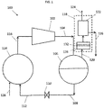
FIG. 1 is a schematic depiction of a heating, ventilation, air conditioning and refrigeration system including a vapor compression heat transfer refrigerant fluid circulation loop with a purge system; -
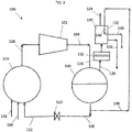
FIG. 2 is a schematic depiction of a mechanical purge system for a heating, ventilation, air conditioning and refrigeration system; and -
FIG. 3 is a schematic depiction of a heating, ventilation, air conditioning and refrigeration system including a vapor compression heat transfer refrigerant fluid circulation loop with a thermal purge system. - A detailed description of one or more embodiments of the disclosed apparatus and method are presented herein by way of exemplification and not limitation with reference to the Figures.
- With reference to
FIG. 1 , a heat transferfluid circulation loop 100 such as can be used in a chiller or other heating, ventilation, air conditioning and refrigeration (HVAC&R) system, is shown in block diagram form inFIG. 1 . As shown inFIG. 1 , acompressor 102 pressurizes heat transfer fluid in its gaseous state, which both heats the fluid and provides pressure to circulate it throughout the system. In some embodiments, the heat transfer fluid, or refrigerant, comprises an organic compound. In some embodiments, the refrigerant comprises a hydrocarbon or substituted hydrocarbon. In some embodiments, the refrigerant comprises a halogen-substituted hydrocarbon. In some embodiments, the refrigerant comprises a fluoro-substituted or chloro-fluoro-substituted hydrocarbon. The hot pressurized gaseous heat transfer fluid exiting from thecompressor 102 flows throughconduit 104 to acondenser 106, which functions as a heat exchanger to transfer heat from the heat transfer fluid to the surrounding environment, resulting in condensation of the hot gaseous heat transfer fluid to a pressurized moderate temperature liquid. The liquid heat transfer fluid exiting from thecondenser 106 flows throughconduit 108 to anexpansion valve 110, where the pressure is reduced. The reduced pressure liquid heat transfer fluid exiting theexpansion valve 110 flows throughconduit 112 to anevaporator 114, which functions as a heat exchanger to absorb heat from the surrounding environment and boil the heat transfer fluid. Gaseous heat transfer fluid exiting theevaporator 114 flows throughconduit 116 to thecompressor 102, thus completing the heat transfer fluid loop. The heat transfer system has the effect of transferring heat from the environment surrounding theevaporator 114 to the environment surrounding thecondenser 106. The thermodynamic properties of the heat transfer fluid must allow it to reach a high enough temperature when compressed so that it is greater than the environment surrounding thecondenser 106, allowing heat to be transferred to the surrounding environment. The thermodynamic properties of the heat transfer fluid must also have a boiling point at its post-expansion pressure that allows the temperature surrounding theevaporator 114 to provide heat to vaporize the liquid heat transfer fluid. - A
purge system 118 is fluidly connected to thecondenser 106 and utilized to remove contaminants, such as air and water moisture from the refrigerant stream. Apurge line 120 extends from thecondenser 106 to thepurge system 118, through which vapor refrigerant flows to thepurge system 118. Thepurge system 118 separates contaminants or non-condensables from the vapor refrigerant at apurge unit 122. The contaminants are released from thepurge unit 112 via avent line 124 to, for example, ambient. The refrigerant is returned to thefluid circulation loop 100 at, for example, theevaporator 114 via areturn line 126. - A
membrane purge unit 128 is located along thepurge line 120 between thecondenser 106 and thepurge unit 122. The membrane purge unit 130 includes amembrane separator 132 configured to allow contaminants such as air, water, oxygen or nitrogen through themembrane separator 132 toward thepurge unit 122 along thepurge line 120, while preventing refrigerant and additives such as vapor pressure corrosion inhibitor (VPCI) present in the refrigerant from flowing through themembrane separator 132. Refrigerants utilized have an average molecular diameter of 0.54nm, while VPCI additives are typically high molecular weight amines and their derivatives having larger molecular diameters. In some embodiments, themembrane separator 132 has a uniform pore size with an average pore diameter of less than 0.50nm to prevent the refrigerant and VPCI additives from passing through themembrane separator 132 to thepurge unit 122. This average pore diameter results in a membrane separator efficiency of approximately 90%. - In some embodiments, the
membrane separator 132 comprises a porous inorganic material. Examples of porous inorganic materials can include ceramics such as metal oxides or metal silicates, more specifically aluminosilicates (e.g., Chabazite Framework (CHA) zeolite, Linde type A (LTA) zeolite), porous carbon, porous glass, clays (e.g., Montmorillonite, Halloysite). Porous inorganic materials can also include porous metals such as platinum and nickel. Hybrid inorganic-organic materials such as a metal organic frameworks (MOF) can also be used. Other materials can be present in the membrane such as a carrier in which a microporous material can be dispersed, which can be included for structural or process considerations. One skilled in the art will readily appreciate that the materials discussed herein are merely exemplary, and that other materials may be utilized. - Referring now to
FIG. 2 , in some embodiments thepurge unit 122 is amechanical purge unit 122, including a vapor compression cycle to remove the contaminants from the refrigerant. Thepurge unit 122 receives refrigerant and contaminants from themembrane separator 132 via thepurge line 120. Thepurge line 120 directs the refrigerant into apurge tank 134, which is one element of a purge vapor compression cycle, including apurge compressor 136, apurge expansion valve 138, apurge evaporator 140 that resides in thepurge tank 134, and apurge condenser 142, which may be air cooled or water cooled. The purge vapor compression cycle utilizes a purge refrigerant flow, which may be the same refrigerant material as the chiller refrigerant, or alternatively may be a different refrigerant material. At thepurge evaporator 140, the purge refrigerant flow exchanges thermal energy with the chiller refrigerant, condenses at least a portion of the chiller refrigerant to a liquid, with a lesser degree of contaminants or non-condensables, which is directed back to theevaporator 114 via thereturn line 126. - Referring now to
FIG. 3 , in another embodiment thepurge unit 122 is athermal purge unit 122. Thethermal purge unit 122 includes apurge condenser 144, having apurge condenser coil 146 through which condensed refrigerant is directed fromconduit 108 viapurge condenser line 148. The vapor refrigerant flows from thepurge line 120 into thepurge condenser 144, where thermal energy exchange with the refrigerant in thecondenser coil 146 condenses the refrigerant vapor into liquid. The condensed refrigerant liquid at thepurge condenser 144 is returned to theevaporator 114 via thereturn line 126, while the non-condensables, such as air, water, and other materials are released from thepurge unit 122 via thevent line 124. Refrigerant flowing through thepurge condenser coil 146 is returned to theevaporator 114 via thecoil return line 150. - Utilizing the
membrane purge unit 128 in combination with thepurge unit 122 allows for a size and/or operational capability of thepurge unit 122 to be reduced, since themembrane purge unit 128 restricts entry of refrigerant into thepurge unit 122. Further, themembrane purge unit 128 reduces depletion of the VPCI concentration in the refrigerant flow through the heat transferfluid circulation loop 100. - The term "about", if used, is intended to include the degree of error associated with measurement of the particular quantity based upon the equipment available at the time of filing the application. For example, "about" can include a range of ± 8% or 5%, or 2% of a given value.
- The terminology used herein is for the purpose of describing particular embodiments only and is not intended to be limiting of the present disclosure. As used herein, the singular forms "a", "an" and "the" are intended to include the plural forms as well, unless the context clearly indicates otherwise. It will be further understood that the terms "comprises" and/or "comprising," when used in this specification, specify the presence of stated features, integers, steps, operations, elements, and/or components, but do not preclude the presence or addition of one or more other features, integers, steps, operations, element components, and/or groups thereof.
- While the present disclosure has been described with reference to an exemplary embodiment or embodiments, it will be understood by those skilled in the art that various changes may be made and equivalents may be substituted for elements thereof without departing from the scope of the present invention as defined by the claims. In addition, many modifications may be made to adapt a particular situation or material to the teachings of the present invention without departing from the scope thereof, as defined by the claims. Therefore, it is intended that the present invention not be limited to the particular embodiment disclosed as the best mode contemplated for carrying out this present invention, but that the present invention will include all embodiments falling within the scope of the claims.
Claims (15)
- A heating, ventilation, air conditioning and refrigeration system comprising:a heat transfer fluid circulation loop (100) configured to circulate a refrigerant therethrough;a purge gas outlet (120) in operable communication with the heat transfer fluid circulation loop;at least one gas permeable membrane (132) having a first side in operable communication with the purge gas outlet (120) and a second side, said membrane comprising a plurality of pores of a size to allow passage of contaminants through the membrane, while restricting passage of the refrigerant through the membrane, and further restricting passage of a vapor phase corrosion inhibiter through the membrane; anda purge unit (122) in operable communication with the second side of the permeable membrane configured to receive a purge gas from the permeable membrane.
- The heating, ventilation, air conditioning and refrigeration system of claim 1, wherein the plurality of pores have an average pore diameter of less than 0.50 nm.
- The heating, ventilation, air conditioning and refrigeration system of claim 1 or 2, wherein the membrane (132) includes a zeolite material.
- The heating, ventilation, air conditioning and refrigeration system of claim 1, 2, or 3, wherein the purge gas outlet (120) directs the purge gas from a condenser (106) of the heat transfer fluid circulation loop (100) to the at least one gas permeable membrane (132).
- The heating, ventilation, air conditioning and refrigeration system of any preceding claim, wherein the purge unit (122) is one of a mechanical purge unit or a thermal purge unit.
- The heating, ventilation, air conditioning and refrigeration system of claim 5, wherein the purge unit (122) is a mechanical purge unit and includes:a purge tank (134);a purge evaporator (140) of a purge vapor compression cycle disposed in the purge tank;a purge line configured to deliver the purge gas from the membrane to the purge tank; anda return line (126) configured to return refrigerant to an evaporator (114) of the heating, ventilation, air conditioning and refrigeration system after thermal energy exchange with a purge refrigerant flow at the purge evaporator.
- The heating, ventilation, air conditioning and refrigeration system of claim 6, wherein the purge vapor compression cycle further includes a purge compressor (136), a purge condenser (142) and a purge expansion valve (138) operably connected to the purge evaporator (140) and configured to circulate the purge refrigerant therethrough.
- The heating, ventilation, air conditioning and refrigeration system of claim 5, wherein the purge unit (122) is a thermal purge unit and comprises:a purge condenser (144) configured to receive purge gas from the membrane (132) via a purge line (120); anda purge condenser coil (146) configured to flow a purge refrigerant therethrough;wherein the refrigerant is condensed at the purge condenser via thermal exchange with the purge refrigerant flowing through the purge coil.
- The heating, ventilation, air conditioning and refrigeration system of claim 8, wherein the purge refrigerant is directed to the purge condenser (144) from a condenser outlet of a condenser (106) of the heating, ventilation, air conditioning and refrigeration system; and/or comprising a purge return line (150) to direct the purge refrigerant to an evaporator (114) of the heating, ventilation, air conditioning and refrigeration system after flowing through the purge condenser coil (146).
- The heating, ventilation, air conditioning and refrigeration system of any preceding claim, further comprising a vent line (124) to vent contaminants from the purge unit (122) to ambient.
- A method of operating a heating, ventilation, air conditioning and refrigeration system, comprising:circulating a refrigerant through a heat transfer fluid circulation loop (100);diverting a purge gas comprising contaminants from a purge gas outlet (120) in the fluid circulation loop;transferring the contaminants across a permeable membrane (132), said membrane comprising a plurality of pores of a size to allow passage of contaminants through the membrane, while restricting passage of the refrigerant through the membrane, and further restricting passage of a vapor phase corrosion inhibiter through the membrane; andurging the purge gas from the permeable membrane to a purge unit (122);separating refrigerant from the contaminants at the purge unit; anddirecting the refrigerant to an evaporator (114) of the heat transfer fluid circulation loop via a return line (126; 150).
- The method of claim 11, further comprising diverting the purge gas from a condenser (106) of the heat transfer fluid circulation loop (100) via the purge gas outlet (120).
- The method of claim 11 or 12, wherein separating refrigerant from the contaminants at the purge unit (122) includes:flowing the purge gas from the permeable membrane (132) to a purge tank (134); andflowing a purge refrigerant through a purge evaporator (140) disposed in the purge tank, the purge evaporator being an element of a purge vapor compression cycle;exchanging thermal energy between the purge gas and the purge refrigerant flowing through the purge evaporator, thereby separating the refrigerant from contaminants.
- The method of claim 11 or 12, wherein separating refrigerant from the contaminants at the purge unit (122) includes:flowing the purge gas from the permeable membrane to a purge condenser (144);urging a purge refrigerant through a purge condenser coil (146) disposed in the purge condenser; andcondensing the refrigerant from the purge gas via thermal energy exchange with the purge refrigerant at the purge condenser, thereby separating the refrigerant from the contaminants; and optionally:urging the purge refrigerant through the purge condenser coil from a condenser outlet of a condenser (106) of the heat transfer fluid circulation loop and/or flowing the purge refrigerant from the purge condenser coil (146) to the evaporator (114) of the heat transfer fluid circulation loop (100).
- The method of any of claims 11 to 14, further comprising venting contaminants to ambient via a vent line (124) at the purge unit (122).
Applications Claiming Priority (1)
| Application Number | Priority Date | Filing Date | Title |
|---|---|---|---|
| US201862623673P | 2018-01-30 | 2018-01-30 |
Publications (2)
| Publication Number | Publication Date |
|---|---|
| EP3517860A1 true EP3517860A1 (en) | 2019-07-31 |
| EP3517860B1 EP3517860B1 (en) | 2022-08-24 |
Family
ID=65041680
Family Applications (1)
| Application Number | Title | Priority Date | Filing Date |
|---|---|---|---|
| EP19152595.5A Active EP3517860B1 (en) | 2018-01-30 | 2019-01-18 | Low pressure integrated purge |
Country Status (4)
| Country | Link |
|---|---|
| US (1) | US11231214B2 (en) |
| EP (1) | EP3517860B1 (en) |
| CN (1) | CN110095013A (en) |
| ES (1) | ES2926341T3 (en) |
Families Citing this family (4)
| Publication number | Priority date | Publication date | Assignee | Title |
|---|---|---|---|---|
| RU2729305C1 (en) * | 2020-02-19 | 2020-08-05 | Анастасия Олеговна Точеная | Air separator for refrigerating system |
| JP7579685B2 (en) * | 2020-11-27 | 2024-11-08 | 三菱重工サーマルシステムズ株式会社 | Condensers and refrigerators |
| CN113340021A (en) * | 2021-05-27 | 2021-09-03 | 五邑大学 | Refrigeration equipment applied to air conditioner |
| EP4501436A1 (en) * | 2023-08-02 | 2025-02-05 | Linde GmbH | METHOD FOR REMOVING AN UNDESIRABLE COMPONENT FROM A COMPRESSOR CIRCUIT |
Citations (3)
| Publication number | Priority date | Publication date | Assignee | Title |
|---|---|---|---|---|
| US5062273A (en) * | 1990-07-12 | 1991-11-05 | E. I. Du Pont De Nemours And Company | Method and apparatus for removal of gas from refrigeration system |
| US20070113581A1 (en) * | 2003-10-22 | 2007-05-24 | Daikin Industries, Ltd. | Method for installing refrigeration device, and refrigeration device |
| US20150059383A1 (en) * | 2013-01-24 | 2015-03-05 | Panasonic Corporation | Heat pump apparatus |
Family Cites Families (27)
| Publication number | Priority date | Publication date | Assignee | Title |
|---|---|---|---|---|
| US5119635A (en) | 1989-06-29 | 1992-06-09 | Ormat Turbines (1965) Ltd. | Method of a means for purging non-condensable gases from condensers |
| US5031410A (en) | 1990-02-21 | 1991-07-16 | American Standard Inc. | Refrigeration system thermal purge apparatus |
| US5044166A (en) | 1990-03-05 | 1991-09-03 | Membrane Technology & Research, Inc. | Refrigeration process with purge and recovery of refrigerant |
| JP2575966B2 (en) | 1990-04-17 | 1997-01-29 | 矢崎総業株式会社 | Absorption chiller / heater |
| US5487765A (en) | 1991-03-27 | 1996-01-30 | Ormat Turbines (1965) Ltd. | Apparatus for purging non-condensable gases from condensers |
| US6128916A (en) | 1997-11-28 | 2000-10-10 | Enerfex, Inc. | Membrane technology to remove non-condensable gases from refrigeration systems |
| US6055821A (en) | 1998-10-08 | 2000-05-02 | Carrier Corporation | Purge system for an absorption air conditioner |
| US6606881B1 (en) | 2002-05-20 | 2003-08-19 | American Standard International Inc. | Absorption solution conditioner |
| US6952938B2 (en) | 2002-05-30 | 2005-10-11 | Redi Controls, Inc. | Purge system and method of use |
| US7130679B2 (en) * | 2002-11-20 | 2006-10-31 | Medtronic, Inc. | Organ rejection monitoring |
| JP3680278B2 (en) | 2003-06-20 | 2005-08-10 | ダイキン工業株式会社 | Refrigeration equipment construction method and refrigeration equipment |
| JP4265369B2 (en) * | 2003-10-22 | 2009-05-20 | ダイキン工業株式会社 | Refrigeration equipment construction method and refrigeration equipment |
| JP2005127563A (en) * | 2003-10-22 | 2005-05-19 | Daikin Ind Ltd | Refrigeration equipment construction method and refrigeration equipment |
| JP2007139347A (en) | 2005-11-21 | 2007-06-07 | Daikin Ind Ltd | Refrigeration apparatus and method for installing the refrigeration apparatus |
| EP2088389B1 (en) * | 2008-02-05 | 2017-05-10 | Evonik Degussa GmbH | Absorption cooling machine |
| JP2009152218A (en) | 2009-04-02 | 2009-07-09 | Hitachi Lighting Ltd | Fluorescent lamp with built-in ballast |
| JP2011248298A (en) | 2010-05-31 | 2011-12-08 | Nof Corp | Method for manufacturing antireflection film |
| US8574342B1 (en) | 2010-12-27 | 2013-11-05 | Charles M. Flowe | Method and apparatus for membrane separation |
| US10190808B2 (en) | 2012-04-30 | 2019-01-29 | Trane International Inc. | Refrigeration system with purge and acid filter |
| US20130283832A1 (en) * | 2012-04-30 | 2013-10-31 | Trane International Inc. | Refrigeration system with purge using enrivonmentally-suitable chiller refrigerant |
| US20160025393A1 (en) | 2013-03-15 | 2016-01-28 | Armstrong International, Inc. | Refrigeration Purger Monitor |
| JP6123526B2 (en) | 2013-07-04 | 2017-05-10 | 株式会社湯山製作所 | Dispensing management system, dispensing management method, dispensing management program |
| US9987568B2 (en) | 2013-08-09 | 2018-06-05 | Carrier Corporation | Purge system for chiller system |
| US20150107294A1 (en) | 2013-10-22 | 2015-04-23 | Panasonic Intellectual Property Management Co., Ltd. | Refrigeration-cycle equipment |
| US10385549B2 (en) * | 2015-05-15 | 2019-08-20 | Seas Société De L'eau Aérienne Suisse Sa | Water production apparatus for rigorous climates |
| CN106322804B (en) * | 2015-06-30 | 2023-03-31 | 开利公司 | Refrigeration system and purification method thereof |
| CN106322805B (en) * | 2015-07-10 | 2020-11-17 | 开利公司 | Refrigeration system and purification method thereof |
-
2019
- 2019-01-18 ES ES19152595T patent/ES2926341T3/en active Active
- 2019-01-18 EP EP19152595.5A patent/EP3517860B1/en active Active
- 2019-01-30 CN CN201910090903.6A patent/CN110095013A/en active Pending
- 2019-01-30 US US16/262,201 patent/US11231214B2/en active Active
Patent Citations (3)
| Publication number | Priority date | Publication date | Assignee | Title |
|---|---|---|---|---|
| US5062273A (en) * | 1990-07-12 | 1991-11-05 | E. I. Du Pont De Nemours And Company | Method and apparatus for removal of gas from refrigeration system |
| US20070113581A1 (en) * | 2003-10-22 | 2007-05-24 | Daikin Industries, Ltd. | Method for installing refrigeration device, and refrigeration device |
| US20150059383A1 (en) * | 2013-01-24 | 2015-03-05 | Panasonic Corporation | Heat pump apparatus |
Also Published As
| Publication number | Publication date |
|---|---|
| US11231214B2 (en) | 2022-01-25 |
| US20190234661A1 (en) | 2019-08-01 |
| EP3517860B1 (en) | 2022-08-24 |
| CN110095013A (en) | 2019-08-06 |
| ES2926341T3 (en) | 2022-10-25 |
Similar Documents
| Publication | Publication Date | Title |
|---|---|---|
| US11231214B2 (en) | Low pressure integrated purge | |
| DK177329B1 (en) | Refrigeration system | |
| CN100397001C (en) | Construction method of freezing device and freezing device thereof | |
| EP2787293A1 (en) | Integrated membrane dehumidification system | |
| US20190381866A1 (en) | Vehicle Having A Two-Stage Cooling System | |
| KR101963911B1 (en) | Vacuum container for removing foreign gases from an adsorption chiller | |
| US5245839A (en) | Adsorption-type refrigerant recovery apparatus | |
| JP2000179963A (en) | Air conditioner | |
| US20230204259A1 (en) | Refrigeration system | |
| JP6821321B2 (en) | Condenser, turbo refrigeration system equipped with this | |
| CN217274955U (en) | System and device for energy recovery | |
| US10634398B2 (en) | Heating, ventilation, air conditioning and refrigeration system | |
| US20230053834A1 (en) | Enhanced economizer operation in a chiller | |
| US20170158025A1 (en) | Heating, ventilation, air conditioning and refrigeration system with dehumidification | |
| US12523401B2 (en) | Refrigerant recovery system and recovery cart thereof | |
| JP2003014331A (en) | Cooling system | |
| CN114174733B (en) | Series flow type refrigerator system | |
| WO2020005071A1 (en) | Apparatus and method for transferring heat | |
| KR102740385B1 (en) | Indoor air cleaning air conditioner system capable of generating oxygen and removing contaminants | |
| JPH03279767A (en) | Refrigerant collection device | |
| JP2006255627A (en) | Dehumidifier | |
| TH94925A (en) | Cooling system | |
| JPH07266847A (en) | Vehicle air conditioner |
Legal Events
| Date | Code | Title | Description |
|---|---|---|---|
| PUAI | Public reference made under article 153(3) epc to a published international application that has entered the european phase |
Free format text: ORIGINAL CODE: 0009012 |
|
| STAA | Information on the status of an ep patent application or granted ep patent |
Free format text: STATUS: THE APPLICATION HAS BEEN PUBLISHED |
|
| AK | Designated contracting states |
Kind code of ref document: A1 Designated state(s): AL AT BE BG CH CY CZ DE DK EE ES FI FR GB GR HR HU IE IS IT LI LT LU LV MC MK MT NL NO PL PT RO RS SE SI SK SM TR |
|
| AX | Request for extension of the european patent |
Extension state: BA ME |
|
| STAA | Information on the status of an ep patent application or granted ep patent |
Free format text: STATUS: REQUEST FOR EXAMINATION WAS MADE |
|
| 17P | Request for examination filed |
Effective date: 20200131 |
|
| RBV | Designated contracting states (corrected) |
Designated state(s): AL AT BE BG CH CY CZ DE DK EE ES FI FR GB GR HR HU IE IS IT LI LT LU LV MC MK MT NL NO PL PT RO RS SE SI SK SM TR |
|
| STAA | Information on the status of an ep patent application or granted ep patent |
Free format text: STATUS: EXAMINATION IS IN PROGRESS |
|
| 17Q | First examination report despatched |
Effective date: 20200430 |
|
| GRAP | Despatch of communication of intention to grant a patent |
Free format text: ORIGINAL CODE: EPIDOSNIGR1 |
|
| STAA | Information on the status of an ep patent application or granted ep patent |
Free format text: STATUS: GRANT OF PATENT IS INTENDED |
|
| INTG | Intention to grant announced |
Effective date: 20220519 |
|
| GRAS | Grant fee paid |
Free format text: ORIGINAL CODE: EPIDOSNIGR3 |
|
| GRAA | (expected) grant |
Free format text: ORIGINAL CODE: 0009210 |
|
| STAA | Information on the status of an ep patent application or granted ep patent |
Free format text: STATUS: THE PATENT HAS BEEN GRANTED |
|
| AK | Designated contracting states |
Kind code of ref document: B1 Designated state(s): AL AT BE BG CH CY CZ DE DK EE ES FI FR GB GR HR HU IE IS IT LI LT LU LV MC MK MT NL NO PL PT RO RS SE SI SK SM TR |
|
| REG | Reference to a national code |
Ref country code: CH Ref legal event code: EP |
|
| REG | Reference to a national code |
Ref country code: DE Ref legal event code: R096 Ref document number: 602019018523 Country of ref document: DE |
|
| REG | Reference to a national code |
Ref country code: IE Ref legal event code: FG4D |
|
| REG | Reference to a national code |
Ref country code: AT Ref legal event code: REF Ref document number: 1513915 Country of ref document: AT Kind code of ref document: T Effective date: 20220915 |
|
| REG | Reference to a national code |
Ref country code: ES Ref legal event code: FG2A Ref document number: 2926341 Country of ref document: ES Kind code of ref document: T3 Effective date: 20221025 |
|
| REG | Reference to a national code |
Ref country code: LT Ref legal event code: MG9D |
|
| REG | Reference to a national code |
Ref country code: NL Ref legal event code: MP Effective date: 20220824 |
|
| PG25 | Lapsed in a contracting state [announced via postgrant information from national office to epo] |
Ref country code: SE Free format text: LAPSE BECAUSE OF FAILURE TO SUBMIT A TRANSLATION OF THE DESCRIPTION OR TO PAY THE FEE WITHIN THE PRESCRIBED TIME-LIMIT Effective date: 20220824 Ref country code: RS Free format text: LAPSE BECAUSE OF FAILURE TO SUBMIT A TRANSLATION OF THE DESCRIPTION OR TO PAY THE FEE WITHIN THE PRESCRIBED TIME-LIMIT Effective date: 20220824 Ref country code: PT Free format text: LAPSE BECAUSE OF FAILURE TO SUBMIT A TRANSLATION OF THE DESCRIPTION OR TO PAY THE FEE WITHIN THE PRESCRIBED TIME-LIMIT Effective date: 20221226 Ref country code: NO Free format text: LAPSE BECAUSE OF FAILURE TO SUBMIT A TRANSLATION OF THE DESCRIPTION OR TO PAY THE FEE WITHIN THE PRESCRIBED TIME-LIMIT Effective date: 20221124 Ref country code: NL Free format text: LAPSE BECAUSE OF FAILURE TO SUBMIT A TRANSLATION OF THE DESCRIPTION OR TO PAY THE FEE WITHIN THE PRESCRIBED TIME-LIMIT Effective date: 20220824 Ref country code: LV Free format text: LAPSE BECAUSE OF FAILURE TO SUBMIT A TRANSLATION OF THE DESCRIPTION OR TO PAY THE FEE WITHIN THE PRESCRIBED TIME-LIMIT Effective date: 20220824 Ref country code: LT Free format text: LAPSE BECAUSE OF FAILURE TO SUBMIT A TRANSLATION OF THE DESCRIPTION OR TO PAY THE FEE WITHIN THE PRESCRIBED TIME-LIMIT Effective date: 20220824 Ref country code: FI Free format text: LAPSE BECAUSE OF FAILURE TO SUBMIT A TRANSLATION OF THE DESCRIPTION OR TO PAY THE FEE WITHIN THE PRESCRIBED TIME-LIMIT Effective date: 20220824 |
|
| REG | Reference to a national code |
Ref country code: AT Ref legal event code: MK05 Ref document number: 1513915 Country of ref document: AT Kind code of ref document: T Effective date: 20220824 |
|
| PG25 | Lapsed in a contracting state [announced via postgrant information from national office to epo] |
Ref country code: PL Free format text: LAPSE BECAUSE OF FAILURE TO SUBMIT A TRANSLATION OF THE DESCRIPTION OR TO PAY THE FEE WITHIN THE PRESCRIBED TIME-LIMIT Effective date: 20220824 Ref country code: IS Free format text: LAPSE BECAUSE OF FAILURE TO SUBMIT A TRANSLATION OF THE DESCRIPTION OR TO PAY THE FEE WITHIN THE PRESCRIBED TIME-LIMIT Effective date: 20221224 Ref country code: HR Free format text: LAPSE BECAUSE OF FAILURE TO SUBMIT A TRANSLATION OF THE DESCRIPTION OR TO PAY THE FEE WITHIN THE PRESCRIBED TIME-LIMIT Effective date: 20220824 Ref country code: GR Free format text: LAPSE BECAUSE OF FAILURE TO SUBMIT A TRANSLATION OF THE DESCRIPTION OR TO PAY THE FEE WITHIN THE PRESCRIBED TIME-LIMIT Effective date: 20221125 |
|
| PG25 | Lapsed in a contracting state [announced via postgrant information from national office to epo] |
Ref country code: SM Free format text: LAPSE BECAUSE OF FAILURE TO SUBMIT A TRANSLATION OF THE DESCRIPTION OR TO PAY THE FEE WITHIN THE PRESCRIBED TIME-LIMIT Effective date: 20220824 Ref country code: RO Free format text: LAPSE BECAUSE OF FAILURE TO SUBMIT A TRANSLATION OF THE DESCRIPTION OR TO PAY THE FEE WITHIN THE PRESCRIBED TIME-LIMIT Effective date: 20220824 Ref country code: DK Free format text: LAPSE BECAUSE OF FAILURE TO SUBMIT A TRANSLATION OF THE DESCRIPTION OR TO PAY THE FEE WITHIN THE PRESCRIBED TIME-LIMIT Effective date: 20220824 Ref country code: CZ Free format text: LAPSE BECAUSE OF FAILURE TO SUBMIT A TRANSLATION OF THE DESCRIPTION OR TO PAY THE FEE WITHIN THE PRESCRIBED TIME-LIMIT Effective date: 20220824 Ref country code: AT Free format text: LAPSE BECAUSE OF FAILURE TO SUBMIT A TRANSLATION OF THE DESCRIPTION OR TO PAY THE FEE WITHIN THE PRESCRIBED TIME-LIMIT Effective date: 20220824 |
|
| REG | Reference to a national code |
Ref country code: DE Ref legal event code: R097 Ref document number: 602019018523 Country of ref document: DE |
|
| PG25 | Lapsed in a contracting state [announced via postgrant information from national office to epo] |
Ref country code: SK Free format text: LAPSE BECAUSE OF FAILURE TO SUBMIT A TRANSLATION OF THE DESCRIPTION OR TO PAY THE FEE WITHIN THE PRESCRIBED TIME-LIMIT Effective date: 20220824 Ref country code: EE Free format text: LAPSE BECAUSE OF FAILURE TO SUBMIT A TRANSLATION OF THE DESCRIPTION OR TO PAY THE FEE WITHIN THE PRESCRIBED TIME-LIMIT Effective date: 20220824 |
|
| PG25 | Lapsed in a contracting state [announced via postgrant information from national office to epo] |
Ref country code: AL Free format text: LAPSE BECAUSE OF FAILURE TO SUBMIT A TRANSLATION OF THE DESCRIPTION OR TO PAY THE FEE WITHIN THE PRESCRIBED TIME-LIMIT Effective date: 20220824 |
|
| PLBE | No opposition filed within time limit |
Free format text: ORIGINAL CODE: 0009261 |
|
| STAA | Information on the status of an ep patent application or granted ep patent |
Free format text: STATUS: NO OPPOSITION FILED WITHIN TIME LIMIT |
|
| P01 | Opt-out of the competence of the unified patent court (upc) registered |
Effective date: 20230527 |
|
| 26N | No opposition filed |
Effective date: 20230525 |
|
| PG25 | Lapsed in a contracting state [announced via postgrant information from national office to epo] |
Ref country code: SI Free format text: LAPSE BECAUSE OF FAILURE TO SUBMIT A TRANSLATION OF THE DESCRIPTION OR TO PAY THE FEE WITHIN THE PRESCRIBED TIME-LIMIT Effective date: 20220824 |
|
| REG | Reference to a national code |
Ref country code: CH Ref legal event code: PL |
|
| PG25 | Lapsed in a contracting state [announced via postgrant information from national office to epo] |
Ref country code: LU Free format text: LAPSE BECAUSE OF NON-PAYMENT OF DUE FEES Effective date: 20230118 |
|
| REG | Reference to a national code |
Ref country code: BE Ref legal event code: MM Effective date: 20230131 |
|
| PG25 | Lapsed in a contracting state [announced via postgrant information from national office to epo] |
Ref country code: LI Free format text: LAPSE BECAUSE OF NON-PAYMENT OF DUE FEES Effective date: 20230131 Ref country code: CH Free format text: LAPSE BECAUSE OF NON-PAYMENT OF DUE FEES Effective date: 20230131 |
|
| PG25 | Lapsed in a contracting state [announced via postgrant information from national office to epo] |
Ref country code: BE Free format text: LAPSE BECAUSE OF NON-PAYMENT OF DUE FEES Effective date: 20230131 |
|
| PG25 | Lapsed in a contracting state [announced via postgrant information from national office to epo] |
Ref country code: IE Free format text: LAPSE BECAUSE OF NON-PAYMENT OF DUE FEES Effective date: 20230118 |
|
| PG25 | Lapsed in a contracting state [announced via postgrant information from national office to epo] |
Ref country code: IT Free format text: LAPSE BECAUSE OF FAILURE TO SUBMIT A TRANSLATION OF THE DESCRIPTION OR TO PAY THE FEE WITHIN THE PRESCRIBED TIME-LIMIT Effective date: 20220824 |
|
| PG25 | Lapsed in a contracting state [announced via postgrant information from national office to epo] |
Ref country code: MC Free format text: LAPSE BECAUSE OF FAILURE TO SUBMIT A TRANSLATION OF THE DESCRIPTION OR TO PAY THE FEE WITHIN THE PRESCRIBED TIME-LIMIT Effective date: 20220824 |
|
| PG25 | Lapsed in a contracting state [announced via postgrant information from national office to epo] |
Ref country code: MC Free format text: LAPSE BECAUSE OF FAILURE TO SUBMIT A TRANSLATION OF THE DESCRIPTION OR TO PAY THE FEE WITHIN THE PRESCRIBED TIME-LIMIT Effective date: 20220824 |
|
| PG25 | Lapsed in a contracting state [announced via postgrant information from national office to epo] |
Ref country code: BG Free format text: LAPSE BECAUSE OF FAILURE TO SUBMIT A TRANSLATION OF THE DESCRIPTION OR TO PAY THE FEE WITHIN THE PRESCRIBED TIME-LIMIT Effective date: 20220824 |
|
| PG25 | Lapsed in a contracting state [announced via postgrant information from national office to epo] |
Ref country code: BG Free format text: LAPSE BECAUSE OF FAILURE TO SUBMIT A TRANSLATION OF THE DESCRIPTION OR TO PAY THE FEE WITHIN THE PRESCRIBED TIME-LIMIT Effective date: 20220824 |
|
| PGFP | Annual fee paid to national office [announced via postgrant information from national office to epo] |
Ref country code: ES Payment date: 20250203 Year of fee payment: 7 |
|
| PG25 | Lapsed in a contracting state [announced via postgrant information from national office to epo] |
Ref country code: CY Free format text: LAPSE BECAUSE OF FAILURE TO SUBMIT A TRANSLATION OF THE DESCRIPTION OR TO PAY THE FEE WITHIN THE PRESCRIBED TIME-LIMIT; INVALID AB INITIO Effective date: 20190118 |
|
| PG25 | Lapsed in a contracting state [announced via postgrant information from national office to epo] |
Ref country code: HU Free format text: LAPSE BECAUSE OF FAILURE TO SUBMIT A TRANSLATION OF THE DESCRIPTION OR TO PAY THE FEE WITHIN THE PRESCRIBED TIME-LIMIT; INVALID AB INITIO Effective date: 20190118 |
|
| PG25 | Lapsed in a contracting state [announced via postgrant information from national office to epo] |
Ref country code: TR Free format text: LAPSE BECAUSE OF FAILURE TO SUBMIT A TRANSLATION OF THE DESCRIPTION OR TO PAY THE FEE WITHIN THE PRESCRIBED TIME-LIMIT Effective date: 20220824 |
|
| PGFP | Annual fee paid to national office [announced via postgrant information from national office to epo] |
Ref country code: GB Payment date: 20251220 Year of fee payment: 8 |
|
| PGFP | Annual fee paid to national office [announced via postgrant information from national office to epo] |
Ref country code: FR Payment date: 20251217 Year of fee payment: 8 |
|
| PGFP | Annual fee paid to national office [announced via postgrant information from national office to epo] |
Ref country code: DE Payment date: 20251217 Year of fee payment: 8 |