EP3517798A1 - Dust cover - Google Patents
Dust cover Download PDFInfo
- Publication number
- EP3517798A1 EP3517798A1 EP17852936.8A EP17852936A EP3517798A1 EP 3517798 A1 EP3517798 A1 EP 3517798A1 EP 17852936 A EP17852936 A EP 17852936A EP 3517798 A1 EP3517798 A1 EP 3517798A1
- Authority
- EP
- European Patent Office
- Prior art keywords
- foreign matter
- diameter opening
- knuckle
- dust cover
- shaft
- Prior art date
- Legal status (The legal status is an assumption and is not a legal conclusion. Google has not performed a legal analysis and makes no representation as to the accuracy of the status listed.)
- Granted
Links
- 239000000428 dust Substances 0.000 title claims abstract description 46
- 230000002093 peripheral effect Effects 0.000 claims abstract description 30
- 238000007599 discharging Methods 0.000 claims abstract description 3
- JEIPFZHSYJVQDO-UHFFFAOYSA-N iron(III) oxide Inorganic materials O=[Fe]O[Fe]=O JEIPFZHSYJVQDO-UHFFFAOYSA-N 0.000 abstract description 17
- 230000003014 reinforcing effect Effects 0.000 description 8
- 238000003780 insertion Methods 0.000 description 6
- 230000037431 insertion Effects 0.000 description 6
- 239000000463 material Substances 0.000 description 5
- 238000009825 accumulation Methods 0.000 description 3
- 238000007796 conventional method Methods 0.000 description 2
- 239000004519 grease Substances 0.000 description 2
- 229920005989 resin Polymers 0.000 description 2
- 239000011347 resin Substances 0.000 description 2
- 230000000694 effects Effects 0.000 description 1
- 239000013013 elastic material Substances 0.000 description 1
- 239000007769 metal material Substances 0.000 description 1
- 239000000057 synthetic resin Substances 0.000 description 1
- 229920003002 synthetic resin Polymers 0.000 description 1
- XLYOFNOQVPJJNP-UHFFFAOYSA-N water Substances O XLYOFNOQVPJJNP-UHFFFAOYSA-N 0.000 description 1
Images




Classifications
-
- F—MECHANICAL ENGINEERING; LIGHTING; HEATING; WEAPONS; BLASTING
- F16—ENGINEERING ELEMENTS AND UNITS; GENERAL MEASURES FOR PRODUCING AND MAINTAINING EFFECTIVE FUNCTIONING OF MACHINES OR INSTALLATIONS; THERMAL INSULATION IN GENERAL
- F16J—PISTONS; CYLINDERS; SEALINGS
- F16J3/00—Diaphragms; Bellows; Bellows pistons
- F16J3/04—Bellows
- F16J3/041—Non-metallic bellows
- F16J3/046—Lubrication or venting arrangements
-
- F—MECHANICAL ENGINEERING; LIGHTING; HEATING; WEAPONS; BLASTING
- F16—ENGINEERING ELEMENTS AND UNITS; GENERAL MEASURES FOR PRODUCING AND MAINTAINING EFFECTIVE FUNCTIONING OF MACHINES OR INSTALLATIONS; THERMAL INSULATION IN GENERAL
- F16J—PISTONS; CYLINDERS; SEALINGS
- F16J15/00—Sealings
- F16J15/16—Sealings between relatively-moving surfaces
- F16J15/34—Sealings between relatively-moving surfaces with slip-ring pressed against a more or less radial face on one member
- F16J15/3404—Sealings between relatively-moving surfaces with slip-ring pressed against a more or less radial face on one member and characterised by parts or details relating to lubrication, cooling or venting of the seal
- F16J15/3408—Sealings between relatively-moving surfaces with slip-ring pressed against a more or less radial face on one member and characterised by parts or details relating to lubrication, cooling or venting of the seal at least one ring having an uneven slipping surface
- F16J15/3412—Sealings between relatively-moving surfaces with slip-ring pressed against a more or less radial face on one member and characterised by parts or details relating to lubrication, cooling or venting of the seal at least one ring having an uneven slipping surface with cavities
-
- F—MECHANICAL ENGINEERING; LIGHTING; HEATING; WEAPONS; BLASTING
- F16—ENGINEERING ELEMENTS AND UNITS; GENERAL MEASURES FOR PRODUCING AND MAINTAINING EFFECTIVE FUNCTIONING OF MACHINES OR INSTALLATIONS; THERMAL INSULATION IN GENERAL
- F16C—SHAFTS; FLEXIBLE SHAFTS; ELEMENTS OR CRANKSHAFT MECHANISMS; ROTARY BODIES OTHER THAN GEARING ELEMENTS; BEARINGS
- F16C11/00—Pivots; Pivotal connections
- F16C11/04—Pivotal connections
- F16C11/06—Ball-joints; Other joints having more than one degree of angular freedom, i.e. universal joints
-
- F—MECHANICAL ENGINEERING; LIGHTING; HEATING; WEAPONS; BLASTING
- F16—ENGINEERING ELEMENTS AND UNITS; GENERAL MEASURES FOR PRODUCING AND MAINTAINING EFFECTIVE FUNCTIONING OF MACHINES OR INSTALLATIONS; THERMAL INSULATION IN GENERAL
- F16C—SHAFTS; FLEXIBLE SHAFTS; ELEMENTS OR CRANKSHAFT MECHANISMS; ROTARY BODIES OTHER THAN GEARING ELEMENTS; BEARINGS
- F16C11/00—Pivots; Pivotal connections
- F16C11/04—Pivotal connections
- F16C11/06—Ball-joints; Other joints having more than one degree of angular freedom, i.e. universal joints
- F16C11/0666—Sealing means between the socket and the inner member shaft
- F16C11/0671—Sealing means between the socket and the inner member shaft allowing operative relative movement of joint parts due to flexing of the sealing means
-
- F—MECHANICAL ENGINEERING; LIGHTING; HEATING; WEAPONS; BLASTING
- F16—ENGINEERING ELEMENTS AND UNITS; GENERAL MEASURES FOR PRODUCING AND MAINTAINING EFFECTIVE FUNCTIONING OF MACHINES OR INSTALLATIONS; THERMAL INSULATION IN GENERAL
- F16J—PISTONS; CYLINDERS; SEALINGS
- F16J15/00—Sealings
- F16J15/50—Sealings between relatively-movable members, by means of a sealing without relatively-moving surfaces, e.g. fluid-tight sealings for transmitting motion through a wall
- F16J15/52—Sealings between relatively-movable members, by means of a sealing without relatively-moving surfaces, e.g. fluid-tight sealings for transmitting motion through a wall by means of sealing bellows or diaphragms
-
- F—MECHANICAL ENGINEERING; LIGHTING; HEATING; WEAPONS; BLASTING
- F16—ENGINEERING ELEMENTS AND UNITS; GENERAL MEASURES FOR PRODUCING AND MAINTAINING EFFECTIVE FUNCTIONING OF MACHINES OR INSTALLATIONS; THERMAL INSULATION IN GENERAL
- F16J—PISTONS; CYLINDERS; SEALINGS
- F16J3/00—Diaphragms; Bellows; Bellows pistons
- F16J3/04—Bellows
-
- F—MECHANICAL ENGINEERING; LIGHTING; HEATING; WEAPONS; BLASTING
- F16—ENGINEERING ELEMENTS AND UNITS; GENERAL MEASURES FOR PRODUCING AND MAINTAINING EFFECTIVE FUNCTIONING OF MACHINES OR INSTALLATIONS; THERMAL INSULATION IN GENERAL
- F16J—PISTONS; CYLINDERS; SEALINGS
- F16J3/00—Diaphragms; Bellows; Bellows pistons
- F16J3/04—Bellows
- F16J3/041—Non-metallic bellows
- F16J3/042—Fastening details
-
- F—MECHANICAL ENGINEERING; LIGHTING; HEATING; WEAPONS; BLASTING
- F16—ENGINEERING ELEMENTS AND UNITS; GENERAL MEASURES FOR PRODUCING AND MAINTAINING EFFECTIVE FUNCTIONING OF MACHINES OR INSTALLATIONS; THERMAL INSULATION IN GENERAL
- F16C—SHAFTS; FLEXIBLE SHAFTS; ELEMENTS OR CRANKSHAFT MECHANISMS; ROTARY BODIES OTHER THAN GEARING ELEMENTS; BEARINGS
- F16C11/00—Pivots; Pivotal connections
- F16C11/04—Pivotal connections
- F16C11/06—Ball-joints; Other joints having more than one degree of angular freedom, i.e. universal joints
- F16C11/0619—Ball-joints; Other joints having more than one degree of angular freedom, i.e. universal joints the female part comprising a blind socket receiving the male part
-
- F—MECHANICAL ENGINEERING; LIGHTING; HEATING; WEAPONS; BLASTING
- F16—ENGINEERING ELEMENTS AND UNITS; GENERAL MEASURES FOR PRODUCING AND MAINTAINING EFFECTIVE FUNCTIONING OF MACHINES OR INSTALLATIONS; THERMAL INSULATION IN GENERAL
- F16C—SHAFTS; FLEXIBLE SHAFTS; ELEMENTS OR CRANKSHAFT MECHANISMS; ROTARY BODIES OTHER THAN GEARING ELEMENTS; BEARINGS
- F16C11/00—Pivots; Pivotal connections
- F16C11/04—Pivotal connections
- F16C11/06—Ball-joints; Other joints having more than one degree of angular freedom, i.e. universal joints
- F16C11/0695—Mounting of ball-joints, e.g. fixing them to a connecting rod
-
- F—MECHANICAL ENGINEERING; LIGHTING; HEATING; WEAPONS; BLASTING
- F16—ENGINEERING ELEMENTS AND UNITS; GENERAL MEASURES FOR PRODUCING AND MAINTAINING EFFECTIVE FUNCTIONING OF MACHINES OR INSTALLATIONS; THERMAL INSULATION IN GENERAL
- F16C—SHAFTS; FLEXIBLE SHAFTS; ELEMENTS OR CRANKSHAFT MECHANISMS; ROTARY BODIES OTHER THAN GEARING ELEMENTS; BEARINGS
- F16C2326/00—Articles relating to transporting
- F16C2326/01—Parts of vehicles in general
- F16C2326/05—Vehicle suspensions, e.g. bearings, pivots or connecting rods used therein
Definitions
- the present invention relates to a dust cover attached to a ball joint.
- the taper alignment ball joint is structured so that a shaft is passed through a knuckle, and then the knuckle is tightened with a nut from above thereof, whereby the knuckle is fixed to a stud.
- the pinch bolt ball joint 550 is configured so that a notch 553a reaching an insertion hole 553e for passing through a shaft 551b from an end portion on the outer peripheral side of the knuckle 553 is provided and a gap C of the notch 553a is fastened by a nut 554a and a bolt 554b, whereby the knuckle 553 is fixed to the stud 551 as illustrated in FIG. 8 and FIG. 9 .
- the gap C is formed in a part of a lower side surface 553c of the knuckle 553 in the pinch bolt ball joint 550 as illustrated in FIG. 9 .
- a dust cover 510 to which the pinch bolt ball joint 550 is attached is not provided with a dust lip which is supposed to be in close contact with the lower side surface 553c of the knuckle 553 with no gap, so that there is a possibility that external foreign matter intrudes between the knuckle 553 and a large diameter opening 530 from the gap C of the notch 553a.
- the present invention has been made in view of the above-described points. It is a technical object of the present invention to provide a dust cover which can prevent the accumulation of external foreign matter or rust of a knuckle between the knuckle and a large diameter opening, and thus prevent wear of a seal portion caused by a contact with the accumulating external foreign matter or rust of the knuckle.
- a dust cover of the present invention which is attached to a ball joint in which a spherical portion in a stud having the spherical portion and a shaft is accommodated in a socket and a knuckle is fastened into the shaft is provided with a large diameter opening fixed to the outer peripheral surface of the socket, a small diameter opening attached to the shaft of the stud, and a film portion connecting the large diameter opening and the small diameter opening, in which the small diameter opening is provided with a seal portion in close contact with the outer peripheral surface of the shaft and a contact portion in close contact with the knuckle, and a foreign matter discharge groove discharging external foreign matter which tends to accumulate on the small diameter opening to the outside are formed in the contact portion.
- the foreign matter discharge groove is preferably disposed obliquely in the radial direction.
- the foreign matter discharge groove preferably has a spiral shape from the inner diameter direction to the outer diameter direction.
- an inclined portion inclined from the side of an outer diameter of the contact portion to the side of the large diameter opening is preferably formed in the small diameter opening.
- a pinch bolt ball joint 50 (hereinafter simply referred to as "ball joint 50") to which the dust cover 10 is attached is provided with a stud 51 having a spherical portion 51a formed in one end and a shaft 51b formed in the other end, a socket 52 turnably holding the spherical portion 51a of the stud 51, and a knuckle 53 fixed to the stud 51 as illustrated in FIG. 1 and FIG. 2 .
- an insertion hole 53e for passing through the shaft 51b is formed in the knuckle 53.
- a notch 53a reaching the insertion hole 53e from an end portion on the outer peripheral side of the knuckle 53 is formed from an upper side surface 53d to a lower side surface 53c of the knuckle 53, and thus a gap C is formed in one end of the knuckle 53 as illustrated in FIG. 2 .
- the shaft 51b is passed through the knuckle 53 and the notch 53a is fastened by a nut 54a and a bolt 54b, whereby the knuckle 53 is fixed to the stud 51.
- the dust cover 10 according to this embodiment is attached.
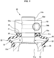
- the dust cover 10 is molded by a rubber-like elastic material (rubber material or synthetic resin material having rubber-like elasticity) and is provided with a large diameter opening 20 having a relatively large diameter tightened and fixed to the outer peripheral surface of the socket 52 of the ball joint 50, a small diameter opening 30 having a relatively small diameter attached to an outer peripheral surface 51c of the shaft 51b of the stud 51 in a close contact state, and a cylindrical film portion 40 connecting the large diameter opening 20 and the small diameter opening 30 as illustrated in FIG. 1 .
- rubber-like elastic material rubber material or synthetic resin material having rubber-like elasticity
- the inner peripheral surface is fitted to an annular level difference portion 52a formed on the outer peripheral surface of the socket 52 with appropriate interference by a snap ring, which is not illustrated, attached to an annular groove in the outer periphery.
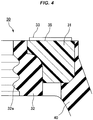
- the small diameter opening 30 is provided with a seal portion 32 formed on the inner peripheral side, a reinforcing ring 31 located on the outer peripheral side of the seal portion 32, and a contact portion 33 which is the upper surface of the reinforcing ring 31 and contacts a lower side surface 53c of the knuckle 53 as illustrated in FIG. 1 , FIG. 3 , and FIG. 4 .
- the seal portion 32 is in close contact with the outer peripheral surface 51c of the stud 51 with appropriate interference and a plurality of seal projections 32a is formed in an end portion on the inner peripheral side of the seal portion 32.
- the reinforcing ring 31 is molded by a resin material so that the contact portion 33 formed on the upper surface is not scraped by the contact with the lower side surface 53c of the knuckle 53. Moreover, the seal portion 32 is integrally molded on the inner peripheral side of the reinforcing ring 31 and the film portion 40 is integrally molded on the outer peripheral side thereof.
- a material of the reinforcing ring 31 is not limited to the resin material and may also be a metal material.
- the contact portion 33 is provided on the reinforcing ring 31 and contacts the lower side surface 53c of the knuckle 53.
- a plurality of foreign matter discharge grooves 35 is molded from the inner peripheral side to the outer peripheral side.
- the plurality of foreign matter discharge grooves 35 is disposed obliquely with a necessary angle in the radial direction of the shaft 51b passed through the insertion hole 53e, extends while being curved from the inner peripheral side to the outer peripheral side, and has a spiral shape as a whole as illustrated in FIG. 3 and FIG. 5 .
- the dust cover 10 having the above-described configuration prevents grease, which is not illustrated, charged into internal space S of the dust cover 10 from flowing out to the outside and prevents external foreign matter from intruding into the internal space S of the dust cover 10 due to the fact that the large diameter opening 20 is fitted to the socket 52 and the seal portion 32 of the small diameter opening 30 is in close contact with the outer peripheral surface 51c of the stud 51 as illustrated in FIG. 1 .
- the film portion 40 is freely deformed as the stud 51 swings to the socket 52.
- the dust cover 10 of the above-described configuration discharges external foreign matter or rust of the knuckle 53 which tends to intrude into the internal space S of the dust cover 10 from the gap C formed by the notch 53a of the knuckle 53 to the outside by the foreign matter discharge grooves 35.
- the external foreign matter or the rust of the knuckle 53 tends to accumulate on the seal portion 32 from the gap C formed by the notch 53a of the knuckle 53
- the external foreign matter or the rust of the knuckle 53 reaches the foreign matter discharge grooves 35 before reaching the seal portion 32 located immediately under the knuckle 53.
- the external foreign matter or the rust of the knuckle 53 which tends to intrude onto the seal portion 32 is discharged from the foreign matter discharge grooves 35 to the outside of the dust cover 10.
- the external foreign matter or the rust of the knuckle 53 which tends to intrude from the outside is discharged to the outside through the foreign matter discharge grooves 35, and therefore the accumulation of the external foreign matter or the rust of the knuckle 53 on the seal portion 32 does not occur.
- This can prevent wear of the seal portion 32 due to the contact of the external foreign matter or the rust of the knuckle 53 with the seal portion 32.
- the foreign matter discharge grooves 35 are disposed obliquely with a necessary angle in the radial direction of the shaft 51b passed through the insertion hole 53e, and therefore breakage due to a twist of the dust cover 10 caused by fitting of the side surfaces of the two foreign matter discharge grooves 35 adjacent to each other into the notch 53a when the stud 51 swings can be prevented.
- the dust cover 10 according to this embodiment is different from the dust cover 10 according to the first embodiment in that an inclined portion 34 is provided on the outside of the contact portion 33 as illustrated in FIG. 6 .
- the inclined portion 34 is formed by cutting out a part of a reinforcing ring 31 and inclines from the inner peripheral side to the outer peripheral side and from the upper side to the lower side.
- the foreign matter discharge grooves 35 incline from the upper side to the lower side, and therefore external foreign matter or rust of the knuckle 53 which tends to intrude from the outside can be more easily discharged to the outside.
- the foreign matter discharge grooves 35 are not limited to those in the aspect described above.
- the foreign matter discharge grooves 35 may have a linear shape or a curved shape from the inner peripheral side to the outer peripheral side. With respect to the direction where the foreign matter discharge grooves 35 are disposed in the radial direction, the foreign matter discharge grooves 35 may be formed radially or may be formed clockwise or counterclockwise.
- the foreign matter discharge grooves 35 which are obliquely disposed with a necessary angle in the radial direction of the shaft 51b, linearly extend to the outer peripheral side from the inner peripheral side, and have a spiral shape as a whole as illustrated in FIG. 7(a) , the foreign matter discharge grooves 35 in which the clockwise foreign matter discharge grooves 35 and the counterclockwise foreign matter discharge grooves 35 are combined as illustrated in FIG. 7(b) , or the foreign matter discharge grooves 35 which are radially formed from the shaft center of the shaft 51b as illustrated in FIG. 7(c) may be acceptable.
Landscapes
- Engineering & Computer Science (AREA)
- General Engineering & Computer Science (AREA)
- Mechanical Engineering (AREA)
- Pivots And Pivotal Connections (AREA)
- Sealing Devices (AREA)
- Diaphragms And Bellows (AREA)
Abstract
Description
- The present invention relates to a dust cover attached to a ball joint.
- Heretofore, to a ball joint, a dust cover preventing the intrusion of external foreign matter, such as muddy water or dust, into the ball joint and preventing grease charged into internal space of the ball joint from flowing out to the outside has been attached.
- As the ball joint to which the dust cover is attached, a so-called taper alignment ball joint which is not illustrated and a so-called pinch
bolt ball joint 550 illustrated inFIG. 8 andFIG. 9 are known. - The taper alignment ball joint is structured so that a shaft is passed through a knuckle, and then the knuckle is tightened with a nut from above thereof, whereby the knuckle is fixed to a stud.
- The pinch
bolt ball joint 550 is configured so that anotch 553a reaching aninsertion hole 553e for passing through ashaft 551b from an end portion on the outer peripheral side of theknuckle 553 is provided and a gap C of thenotch 553a is fastened by anut 554a and abolt 554b, whereby theknuckle 553 is fixed to thestud 551 as illustrated inFIG. 8 andFIG. 9 . - However, the gap C is formed in a part of a
lower side surface 553c of theknuckle 553 in the pinchbolt ball joint 550 as illustrated inFIG. 9 . - Therefore, a
dust cover 510 to which the pinchbolt ball joint 550 is attached is not provided with a dust lip which is supposed to be in close contact with thelower side surface 553c of theknuckle 553 with no gap, so that there is a possibility that external foreign matter intrudes between theknuckle 553 and a large diameter opening 530 from the gap C of thenotch 553a. - Thus, there has been a possibility that the intruding external foreign matter or rust of the
knuckle 553 accumulates between theknuckle 553 and the large diameter opening 530, and then aseal portion 532 in the large diameter opening 530 contacts the accumulating external foreign matter or rust of theknuckle 553 to wear out, so that theseal portion 532 cannot seal internal space S of the dust cover over the long period of time. -
- Patent Document 1: Japanese Unexamined Patent Application Publication No.
2003-172334 - Patent Document 2: Japanese Unexamined Patent Application Publication No.
11-108044 - The present invention has been made in view of the above-described points. It is a technical object of the present invention to provide a dust cover which can prevent the accumulation of external foreign matter or rust of a knuckle between the knuckle and a large diameter opening, and thus prevent wear of a seal portion caused by a contact with the accumulating external foreign matter or rust of the knuckle.
- As a measure for solving the technical problem described above, a dust cover of the present invention which is attached to a ball joint in which a spherical portion in a stud having the spherical portion and a shaft is accommodated in a socket and a knuckle is fastened into the shaft is provided with a large diameter opening fixed to the outer peripheral surface of the socket, a small diameter opening attached to the shaft of the stud, and a film portion connecting the large diameter opening and the small diameter opening, in which the small diameter opening is provided with a seal portion in close contact with the outer peripheral surface of the shaft and a contact portion in close contact with the knuckle, and a foreign matter discharge groove discharging external foreign matter which tends to accumulate on the small diameter opening to the outside are formed in the contact portion.
- In the present invention, the foreign matter discharge groove is preferably disposed obliquely in the radial direction.
- In the present invention, the foreign matter discharge groove preferably has a spiral shape from the inner diameter direction to the outer diameter direction.
- In the present invention, an inclined portion inclined from the side of an outer diameter of the contact portion to the side of the large diameter opening is preferably formed in the small diameter opening.
- According to the dust cover of the present invention, external foreign matter or rust of the knuckle which tends to intrude from the outside is discharged to the outside by the foreign matter discharge groove. Therefore, the accumulation of the external foreign matter or the rust of the knuckle between the knuckle and the large diameter opening can be prevented, and thus the wear of the seal portion caused by the contacting with the accumulating foreign matter or rust of the knuckle can be prevented.
-
-
FIG. 1 is a cross-sectional view illustrating an attachment state of a dust cover according to a first embodiment of the present invention. -
FIG. 2 is a plan view illustrating the attachment state of the dust cover according to the first embodiment of the present invention. -
FIG. 3 is a cross-sectional perspective view of the dust cover according to the first embodiment of the present invention. -
FIG. 4 is an enlarged cross-sectional view of a principal portion of a small diameter opening in the dust cover according to the first embodiment of the present invention. -
FIG. 5 is a plan view illustrating a foreign matter discharge groove in the dust cover according to the first embodiment of the present invention. -
FIG. 6 is an enlarged cross-sectional view of a principal portion of a small diameter opening in a dust cover according to a second embodiment of the present invention. -
FIG. 7(a), FIG. 7(b), and FIG. 7(c) are plan views illustrating examples of the foreign matter discharge groove in the dust cover according to the embodiment of the present invention. -
FIG. 8 is a cross-sectional view illustrating an attachment state of a dust cover according to a conventional technique. -
FIG. 9 is a plan view illustrating the attachment state of the dust cover according to the conventional technique. - Hereinafter, a
dust cover 10 according to a first embodiment of the present invention is described in detail with reference to the drawings. - A pinch bolt ball joint 50 (hereinafter simply referred to as "
ball joint 50") to which thedust cover 10 is attached is provided with astud 51 having aspherical portion 51a formed in one end and ashaft 51b formed in the other end, asocket 52 turnably holding thespherical portion 51a of thestud 51, and aknuckle 53 fixed to thestud 51 as illustrated inFIG. 1 andFIG. 2 . - In the
knuckle 53, aninsertion hole 53e for passing through theshaft 51b is formed. Moreover, in theknuckle 53, anotch 53a reaching theinsertion hole 53e from an end portion on the outer peripheral side of theknuckle 53 is formed from anupper side surface 53d to alower side surface 53c of theknuckle 53, and thus a gap C is formed in one end of theknuckle 53 as illustrated inFIG. 2 . Then, theshaft 51b is passed through theknuckle 53 and thenotch 53a is fastened by anut 54a and abolt 54b, whereby theknuckle 53 is fixed to thestud 51. To the above-describedball joint 50, thedust cover 10 according to this embodiment is attached. - The
dust cover 10 is molded by a rubber-like elastic material (rubber material or synthetic resin material having rubber-like elasticity) and is provided with a large diameter opening 20 having a relatively large diameter tightened and fixed to the outer peripheral surface of thesocket 52 of theball joint 50, a small diameter opening 30 having a relatively small diameter attached to an outerperipheral surface 51c of theshaft 51b of thestud 51 in a close contact state, and acylindrical film portion 40 connecting the large diameter opening 20 and the small diameter opening 30 as illustrated inFIG. 1 . - In the large diameter opening 20, the inner peripheral surface is fitted to an annular
level difference portion 52a formed on the outer peripheral surface of thesocket 52 with appropriate interference by a snap ring, which is not illustrated, attached to an annular groove in the outer periphery. - The small diameter opening 30 is provided with a
seal portion 32 formed on the inner peripheral side, a reinforcingring 31 located on the outer peripheral side of theseal portion 32, and acontact portion 33 which is the upper surface of the reinforcingring 31 and contacts alower side surface 53c of theknuckle 53 as illustrated inFIG. 1 ,FIG. 3 , andFIG. 4 . - The
seal portion 32 is in close contact with the outerperipheral surface 51c of thestud 51 with appropriate interference and a plurality ofseal projections 32a is formed in an end portion on the inner peripheral side of theseal portion 32. - The reinforcing
ring 31 is molded by a resin material so that thecontact portion 33 formed on the upper surface is not scraped by the contact with thelower side surface 53c of theknuckle 53. Moreover, theseal portion 32 is integrally molded on the inner peripheral side of the reinforcingring 31 and thefilm portion 40 is integrally molded on the outer peripheral side thereof. A material of the reinforcingring 31 is not limited to the resin material and may also be a metal material. - The
contact portion 33 is provided on the reinforcingring 31 and contacts thelower side surface 53c of theknuckle 53. In thecontact portion 33, a plurality of foreignmatter discharge grooves 35 is molded from the inner peripheral side to the outer peripheral side. - The plurality of foreign
matter discharge grooves 35 is disposed obliquely with a necessary angle in the radial direction of theshaft 51b passed through theinsertion hole 53e, extends while being curved from the inner peripheral side to the outer peripheral side, and has a spiral shape as a whole as illustrated inFIG. 3 andFIG. 5 . - The
dust cover 10 having the above-described configuration prevents grease, which is not illustrated, charged into internal space S of thedust cover 10 from flowing out to the outside and prevents external foreign matter from intruding into the internal space S of thedust cover 10 due to the fact that the large diameter opening 20 is fitted to thesocket 52 and theseal portion 32 of the small diameter opening 30 is in close contact with the outerperipheral surface 51c of thestud 51 as illustrated inFIG. 1 . - Moreover, according to the
dust cover 10 having the above-described configuration, thefilm portion 40 is freely deformed as thestud 51 swings to thesocket 52. - Moreover, the dust cover 10 of the above-described configuration discharges external foreign matter or rust of the
knuckle 53 which tends to intrude into the internal space S of thedust cover 10 from the gap C formed by thenotch 53a of theknuckle 53 to the outside by the foreignmatter discharge grooves 35. When described in detail, even when the external foreign matter or the rust of theknuckle 53 tends to accumulate on theseal portion 32 from the gap C formed by thenotch 53a of theknuckle 53, the external foreign matter or the rust of theknuckle 53 reaches the foreignmatter discharge grooves 35 before reaching theseal portion 32 located immediately under theknuckle 53. Thus, the external foreign matter or the rust of theknuckle 53 which tends to intrude onto theseal portion 32 is discharged from the foreignmatter discharge grooves 35 to the outside of thedust cover 10. - As described above, according to the
dust cover 10 of this embodiment, the external foreign matter or the rust of theknuckle 53 which tends to intrude from the outside is discharged to the outside through the foreignmatter discharge grooves 35, and therefore the accumulation of the external foreign matter or the rust of theknuckle 53 on theseal portion 32 does not occur. This can prevent wear of theseal portion 32 due to the contact of the external foreign matter or the rust of theknuckle 53 with theseal portion 32. - Moreover, according to the
dust cover 10 of this embodiment, the foreignmatter discharge grooves 35 are disposed obliquely with a necessary angle in the radial direction of theshaft 51b passed through theinsertion hole 53e, and therefore breakage due to a twist of thedust cover 10 caused by fitting of the side surfaces of the two foreignmatter discharge grooves 35 adjacent to each other into thenotch 53a when thestud 51 swings can be prevented. - Next, a
dust cover 10 according to a second embodiment of the present invention is described in detail with reference to the drawings. - More specifically, the
dust cover 10 according to this embodiment is different from thedust cover 10 according to the first embodiment in that aninclined portion 34 is provided on the outside of thecontact portion 33 as illustrated inFIG. 6 . - The
inclined portion 34 is formed by cutting out a part of a reinforcingring 31 and inclines from the inner peripheral side to the outer peripheral side and from the upper side to the lower side. - As described above, according to the
dust cover 10 of this embodiment, the foreignmatter discharge grooves 35 incline from the upper side to the lower side, and therefore external foreign matter or rust of theknuckle 53 which tends to intrude from the outside can be more easily discharged to the outside. - The foreign
matter discharge grooves 35 according to this embodiment are not limited to those in the aspect described above. The foreignmatter discharge grooves 35 may have a linear shape or a curved shape from the inner peripheral side to the outer peripheral side. With respect to the direction where the foreignmatter discharge grooves 35 are disposed in the radial direction, the foreignmatter discharge grooves 35 may be formed radially or may be formed clockwise or counterclockwise. - As an example of the foreign
matter discharge groove 35 having a shape different from the shape of the foreignmatter discharge groove 35 according to this embodiment, the foreignmatter discharge grooves 35 which are obliquely disposed with a necessary angle in the radial direction of theshaft 51b, linearly extend to the outer peripheral side from the inner peripheral side, and have a spiral shape as a whole as illustrated inFIG. 7(a) , the foreignmatter discharge grooves 35 in which the clockwise foreignmatter discharge grooves 35 and the counterclockwise foreignmatter discharge grooves 35 are combined as illustrated inFIG. 7(b) , or the foreignmatter discharge grooves 35 which are radially formed from the shaft center of theshaft 51b as illustrated inFIG. 7(c) may be acceptable. -
- 10
- dust cover
- 20
- large diameter opening
- 30
- small diameter opening
- 31
- reinforcing ring
- 32
- seal portion
- 32a
- seal projection
- 33
- contact portion
- 34
- inclined portion
- 35
- foreign matter discharge groove
- 40
- film portion
- 50
- ball joint
- 51
- stud
- 51a
- spherical portion
- 51b
- shaft
- 51c
- outer peripheral surface
- 52
- socket
- 52a
- annular level difference portion
- 53
- knuckle
- 53a
- notch
- 53b
- side surface
- 53c
- lower side surface
- 53d
- upper side surface
- 53e
- insertion hole
- 54a
- nut
- 54b
- bolt
- C
- gap
- S
- internal space
Claims (4)
- A dust cover which is attached to a ball joint in which a spherical portion in a stud having the spherical portion and a shaft is accommodated in a socket and a knuckle is fastened into the shaft, the dust cover comprising:a large diameter opening fixed to an outer peripheral surface of the socket;a small diameter opening attached to the shaft of the stud; anda film portion connecting the large diameter opening and the small diameter opening, whereinthe small diameter opening is provided with a seal portion in close contact with an outer peripheral surface of the shaft and a contact portion in close contact with the knuckle, anda foreign matter discharge groove discharging external foreign matter which tends to accumulate on the small diameter opening to an outside are formed in the contact portion.
- The dust cover according to Claim 1, wherein
the foreign matter discharge groove is disposed obliquely in a radial direction. - The dust cover according to Claim 2, wherein
the foreign matter discharge groove has a spiral shape from an inner diameter direction to an outer diameter direction. - The dust cover according to any one of Claims 1 to 3, wherein
an inclined portion inclined from a side of an outer diameter of the contact portion to a side of the large diameter opening is formed in the small diameter opening.
Applications Claiming Priority (2)
| Application Number | Priority Date | Filing Date | Title |
|---|---|---|---|
| JP2016184047 | 2016-09-21 | ||
| PCT/JP2017/033221 WO2018056159A1 (en) | 2016-09-21 | 2017-09-14 | Dust cover |
Publications (3)
| Publication Number | Publication Date |
|---|---|
| EP3517798A1 true EP3517798A1 (en) | 2019-07-31 |
| EP3517798A4 EP3517798A4 (en) | 2019-10-09 |
| EP3517798B1 EP3517798B1 (en) | 2020-05-13 |
Family
ID=61690406
Family Applications (1)
| Application Number | Title | Priority Date | Filing Date |
|---|---|---|---|
| EP17852936.8A Active EP3517798B1 (en) | 2016-09-21 | 2017-09-14 | Dust cover |
Country Status (5)
| Country | Link |
|---|---|
| US (1) | US10914379B2 (en) |
| EP (1) | EP3517798B1 (en) |
| JP (1) | JP6387206B2 (en) |
| CN (1) | CN109563872A (en) |
| WO (1) | WO2018056159A1 (en) |
Families Citing this family (2)
| Publication number | Priority date | Publication date | Assignee | Title |
|---|---|---|---|---|
| DE102017209890A1 (en) * | 2017-06-12 | 2018-12-13 | Zf Friedrichshafen Ag | Ball joint for a two-point link and two-point link with such a ball joint |
| CN115031127A (en) * | 2022-04-18 | 2022-09-09 | 北京市政建设集团有限责任公司 | Environment surveying device for rail transit construction |
Family Cites Families (20)
| Publication number | Priority date | Publication date | Assignee | Title |
|---|---|---|---|---|
| US2559857A (en) * | 1948-10-28 | 1951-07-10 | Chrysler Corp | Seal |
| JPS6243869U (en) | 1985-09-02 | 1987-03-17 | ||
| GB9214282D0 (en) * | 1992-07-04 | 1992-08-19 | Crane John Uk Ltd | Seals |
| JPH08200517A (en) | 1995-01-27 | 1996-08-06 | Kiipaa Kk | Dust cover for ball joint |
| DE19727494B4 (en) * | 1997-06-27 | 2014-02-27 | Zf Friedrichshafen Ag | Elastic sealing element in bellows form |
| JP3663849B2 (en) | 1997-08-21 | 2005-06-22 | Nok株式会社 | Dust cover |
| JP3412480B2 (en) | 1997-10-09 | 2003-06-03 | 三菱自動車工業株式会社 | Ball joint |
| ITMI20010963A1 (en) * | 2001-05-10 | 2002-11-10 | Rft Spa | SEALING COMPLEX FOR MECHANICAL ORGANS RELATIVELY ROTATING |
| DE10124295C5 (en) * | 2001-05-17 | 2008-09-04 | ZF Lemförder GmbH | ball joint |
| JP3988024B2 (en) | 2001-12-07 | 2007-10-10 | Nok株式会社 | Dust cover |
| JP2006275259A (en) * | 2005-03-30 | 2006-10-12 | Ntn Corp | Constant velocity universal joint |
| JP2007278352A (en) * | 2006-04-04 | 2007-10-25 | Nok Corp | Ball joint dust cover |
| DE102006021862B4 (en) * | 2006-05-09 | 2009-02-19 | Zf Friedrichshafen Ag | Joint arrangement for a vehicle |
| EP2058563B1 (en) * | 2007-11-06 | 2010-07-28 | CORCOS INDUSTRIALE S.a.s. di Externa Italia S.r.l. | Seal assembly for a rotating member |
| US20090289424A1 (en) | 2008-05-20 | 2009-11-26 | Freudenberg-Nok General Partnership | Ball Joint Dust Seal With Lubricating Flutes |
| JP6025024B2 (en) * | 2012-02-02 | 2016-11-16 | Nok株式会社 | Dust cover for ball joint |
| JP6054135B2 (en) * | 2012-10-23 | 2016-12-27 | Nok株式会社 | Oil seal |
| WO2015190450A1 (en) * | 2014-06-10 | 2015-12-17 | Nok株式会社 | Seal device |
| WO2016111303A1 (en) * | 2015-01-08 | 2016-07-14 | Nok株式会社 | Sealing device |
| WO2017018168A1 (en) * | 2015-07-27 | 2017-02-02 | Nok株式会社 | Ball joint dust cover |
-
2017
- 2017-09-14 US US16/330,656 patent/US10914379B2/en active Active
- 2017-09-14 CN CN201780047382.5A patent/CN109563872A/en active Pending
- 2017-09-14 WO PCT/JP2017/033221 patent/WO2018056159A1/en not_active Ceased
- 2017-09-14 EP EP17852936.8A patent/EP3517798B1/en active Active
- 2017-09-14 JP JP2018510527A patent/JP6387206B2/en active Active
Also Published As
| Publication number | Publication date |
|---|---|
| US20190226581A1 (en) | 2019-07-25 |
| JPWO2018056159A1 (en) | 2018-09-20 |
| CN109563872A (en) | 2019-04-02 |
| EP3517798B1 (en) | 2020-05-13 |
| EP3517798A4 (en) | 2019-10-09 |
| US10914379B2 (en) | 2021-02-09 |
| WO2018056159A1 (en) | 2018-03-29 |
| JP6387206B2 (en) | 2018-09-05 |
Similar Documents
| Publication | Publication Date | Title |
|---|---|---|
| US8899838B2 (en) | Ball retaining cage for bearings and a deep groove ball bearing | |
| US10527101B2 (en) | Bearing sealing device | |
| EP3336395A1 (en) | Sealing device | |
| JP5327603B2 (en) | Rolling bearing device | |
| JP6025024B2 (en) | Dust cover for ball joint | |
| US6123338A (en) | Radial seal for ball bearing | |
| JP6903871B2 (en) | Ball bearing | |
| US20070230853A1 (en) | Bearing device for wheel | |
| CN102588446A (en) | Triple-lip seals for bearings and bearings containing such seals | |
| US10415643B2 (en) | Rolling bearing | |
| JP7164401B2 (en) | sealing device | |
| EP3517798B1 (en) | Dust cover | |
| US20110305411A1 (en) | Roller Bearing Cage | |
| JPWO2016158211A1 (en) | Sealing device | |
| CN111225808A (en) | Plane bearing | |
| US10788075B2 (en) | Ball bearing | |
| US10718372B2 (en) | Dust boot for a moveable joint | |
| CN210034185U (en) | Sealing device | |
| WO2017018169A1 (en) | Ball joint dust cover | |
| CN115704426A (en) | Bearing unit | |
| JP5598131B2 (en) | Ball screw device | |
| CN106996420B (en) | Ball bearing comprising a cage provided with wires and a seal | |
| CN105697540B (en) | Rolling bearings including sealing flanges | |
| JP2008128378A (en) | Sealing device | |
| JP7125131B2 (en) | Retaining rings for linear motion bearings and linear motion bearings |
Legal Events
| Date | Code | Title | Description |
|---|---|---|---|
| STAA | Information on the status of an ep patent application or granted ep patent |
Free format text: STATUS: THE INTERNATIONAL PUBLICATION HAS BEEN MADE |
|
| PUAI | Public reference made under article 153(3) epc to a published international application that has entered the european phase |
Free format text: ORIGINAL CODE: 0009012 |
|
| STAA | Information on the status of an ep patent application or granted ep patent |
Free format text: STATUS: REQUEST FOR EXAMINATION WAS MADE |
|
| 17P | Request for examination filed |
Effective date: 20190212 |
|
| AK | Designated contracting states |
Kind code of ref document: A1 Designated state(s): AL AT BE BG CH CY CZ DE DK EE ES FI FR GB GR HR HU IE IS IT LI LT LU LV MC MK MT NL NO PL PT RO RS SE SI SK SM TR |
|
| AX | Request for extension of the european patent |
Extension state: BA ME |
|
| A4 | Supplementary search report drawn up and despatched |
Effective date: 20190911 |
|
| RIC1 | Information provided on ipc code assigned before grant |
Ipc: F16J 3/04 20060101ALI20190905BHEP Ipc: F16C 11/06 20060101AFI20190905BHEP Ipc: F16J 15/52 20060101ALI20190905BHEP |
|
| GRAP | Despatch of communication of intention to grant a patent |
Free format text: ORIGINAL CODE: EPIDOSNIGR1 |
|
| STAA | Information on the status of an ep patent application or granted ep patent |
Free format text: STATUS: GRANT OF PATENT IS INTENDED |
|
| DAV | Request for validation of the european patent (deleted) | ||
| DAX | Request for extension of the european patent (deleted) | ||
| INTG | Intention to grant announced |
Effective date: 20191218 |
|
| GRAS | Grant fee paid |
Free format text: ORIGINAL CODE: EPIDOSNIGR3 |
|
| GRAA | (expected) grant |
Free format text: ORIGINAL CODE: 0009210 |
|
| STAA | Information on the status of an ep patent application or granted ep patent |
Free format text: STATUS: THE PATENT HAS BEEN GRANTED |
|
| AK | Designated contracting states |
Kind code of ref document: B1 Designated state(s): AL AT BE BG CH CY CZ DE DK EE ES FI FR GB GR HR HU IE IS IT LI LT LU LV MC MK MT NL NO PL PT RO RS SE SI SK SM TR |
|
| REG | Reference to a national code |
Ref country code: GB Ref legal event code: FG4D |
|
| REG | Reference to a national code |
Ref country code: CH Ref legal event code: EP |
|
| REG | Reference to a national code |
Ref country code: DE Ref legal event code: R096 Ref document number: 602017016891 Country of ref document: DE |
|
| REG | Reference to a national code |
Ref country code: AT Ref legal event code: REF Ref document number: 1270676 Country of ref document: AT Kind code of ref document: T Effective date: 20200615 |
|
| REG | Reference to a national code |
Ref country code: LT Ref legal event code: MG4D |
|
| REG | Reference to a national code |
Ref country code: NL Ref legal event code: MP Effective date: 20200513 |
|
| PG25 | Lapsed in a contracting state [announced via postgrant information from national office to epo] |
Ref country code: NO Free format text: LAPSE BECAUSE OF FAILURE TO SUBMIT A TRANSLATION OF THE DESCRIPTION OR TO PAY THE FEE WITHIN THE PRESCRIBED TIME-LIMIT Effective date: 20200813 Ref country code: GR Free format text: LAPSE BECAUSE OF FAILURE TO SUBMIT A TRANSLATION OF THE DESCRIPTION OR TO PAY THE FEE WITHIN THE PRESCRIBED TIME-LIMIT Effective date: 20200814 Ref country code: LT Free format text: LAPSE BECAUSE OF FAILURE TO SUBMIT A TRANSLATION OF THE DESCRIPTION OR TO PAY THE FEE WITHIN THE PRESCRIBED TIME-LIMIT Effective date: 20200513 Ref country code: SE Free format text: LAPSE BECAUSE OF FAILURE TO SUBMIT A TRANSLATION OF THE DESCRIPTION OR TO PAY THE FEE WITHIN THE PRESCRIBED TIME-LIMIT Effective date: 20200513 Ref country code: PT Free format text: LAPSE BECAUSE OF FAILURE TO SUBMIT A TRANSLATION OF THE DESCRIPTION OR TO PAY THE FEE WITHIN THE PRESCRIBED TIME-LIMIT Effective date: 20200914 Ref country code: IS Free format text: LAPSE BECAUSE OF FAILURE TO SUBMIT A TRANSLATION OF THE DESCRIPTION OR TO PAY THE FEE WITHIN THE PRESCRIBED TIME-LIMIT Effective date: 20200913 Ref country code: FI Free format text: LAPSE BECAUSE OF FAILURE TO SUBMIT A TRANSLATION OF THE DESCRIPTION OR TO PAY THE FEE WITHIN THE PRESCRIBED TIME-LIMIT Effective date: 20200513 |
|
| PG25 | Lapsed in a contracting state [announced via postgrant information from national office to epo] |
Ref country code: HR Free format text: LAPSE BECAUSE OF FAILURE TO SUBMIT A TRANSLATION OF THE DESCRIPTION OR TO PAY THE FEE WITHIN THE PRESCRIBED TIME-LIMIT Effective date: 20200513 Ref country code: LV Free format text: LAPSE BECAUSE OF FAILURE TO SUBMIT A TRANSLATION OF THE DESCRIPTION OR TO PAY THE FEE WITHIN THE PRESCRIBED TIME-LIMIT Effective date: 20200513 Ref country code: BG Free format text: LAPSE BECAUSE OF FAILURE TO SUBMIT A TRANSLATION OF THE DESCRIPTION OR TO PAY THE FEE WITHIN THE PRESCRIBED TIME-LIMIT Effective date: 20200813 Ref country code: RS Free format text: LAPSE BECAUSE OF FAILURE TO SUBMIT A TRANSLATION OF THE DESCRIPTION OR TO PAY THE FEE WITHIN THE PRESCRIBED TIME-LIMIT Effective date: 20200513 |
|
| REG | Reference to a national code |
Ref country code: AT Ref legal event code: MK05 Ref document number: 1270676 Country of ref document: AT Kind code of ref document: T Effective date: 20200513 |
|
| PG25 | Lapsed in a contracting state [announced via postgrant information from national office to epo] |
Ref country code: AL Free format text: LAPSE BECAUSE OF FAILURE TO SUBMIT A TRANSLATION OF THE DESCRIPTION OR TO PAY THE FEE WITHIN THE PRESCRIBED TIME-LIMIT Effective date: 20200513 Ref country code: NL Free format text: LAPSE BECAUSE OF FAILURE TO SUBMIT A TRANSLATION OF THE DESCRIPTION OR TO PAY THE FEE WITHIN THE PRESCRIBED TIME-LIMIT Effective date: 20200513 |
|
| PG25 | Lapsed in a contracting state [announced via postgrant information from national office to epo] |
Ref country code: RO Free format text: LAPSE BECAUSE OF FAILURE TO SUBMIT A TRANSLATION OF THE DESCRIPTION OR TO PAY THE FEE WITHIN THE PRESCRIBED TIME-LIMIT Effective date: 20200513 Ref country code: CZ Free format text: LAPSE BECAUSE OF FAILURE TO SUBMIT A TRANSLATION OF THE DESCRIPTION OR TO PAY THE FEE WITHIN THE PRESCRIBED TIME-LIMIT Effective date: 20200513 Ref country code: ES Free format text: LAPSE BECAUSE OF FAILURE TO SUBMIT A TRANSLATION OF THE DESCRIPTION OR TO PAY THE FEE WITHIN THE PRESCRIBED TIME-LIMIT Effective date: 20200513 Ref country code: SM Free format text: LAPSE BECAUSE OF FAILURE TO SUBMIT A TRANSLATION OF THE DESCRIPTION OR TO PAY THE FEE WITHIN THE PRESCRIBED TIME-LIMIT Effective date: 20200513 Ref country code: EE Free format text: LAPSE BECAUSE OF FAILURE TO SUBMIT A TRANSLATION OF THE DESCRIPTION OR TO PAY THE FEE WITHIN THE PRESCRIBED TIME-LIMIT Effective date: 20200513 Ref country code: DK Free format text: LAPSE BECAUSE OF FAILURE TO SUBMIT A TRANSLATION OF THE DESCRIPTION OR TO PAY THE FEE WITHIN THE PRESCRIBED TIME-LIMIT Effective date: 20200513 Ref country code: IT Free format text: LAPSE BECAUSE OF FAILURE TO SUBMIT A TRANSLATION OF THE DESCRIPTION OR TO PAY THE FEE WITHIN THE PRESCRIBED TIME-LIMIT Effective date: 20200513 Ref country code: AT Free format text: LAPSE BECAUSE OF FAILURE TO SUBMIT A TRANSLATION OF THE DESCRIPTION OR TO PAY THE FEE WITHIN THE PRESCRIBED TIME-LIMIT Effective date: 20200513 |
|
| REG | Reference to a national code |
Ref country code: DE Ref legal event code: R097 Ref document number: 602017016891 Country of ref document: DE |
|
| PG25 | Lapsed in a contracting state [announced via postgrant information from national office to epo] |
Ref country code: SK Free format text: LAPSE BECAUSE OF FAILURE TO SUBMIT A TRANSLATION OF THE DESCRIPTION OR TO PAY THE FEE WITHIN THE PRESCRIBED TIME-LIMIT Effective date: 20200513 Ref country code: PL Free format text: LAPSE BECAUSE OF FAILURE TO SUBMIT A TRANSLATION OF THE DESCRIPTION OR TO PAY THE FEE WITHIN THE PRESCRIBED TIME-LIMIT Effective date: 20200513 |
|
| PLBE | No opposition filed within time limit |
Free format text: ORIGINAL CODE: 0009261 |
|
| STAA | Information on the status of an ep patent application or granted ep patent |
Free format text: STATUS: NO OPPOSITION FILED WITHIN TIME LIMIT |
|
| 26N | No opposition filed |
Effective date: 20210216 |
|
| REG | Reference to a national code |
Ref country code: CH Ref legal event code: PL |
|
| REG | Reference to a national code |
Ref country code: BE Ref legal event code: MM Effective date: 20200930 |
|
| PG25 | Lapsed in a contracting state [announced via postgrant information from national office to epo] |
Ref country code: LU Free format text: LAPSE BECAUSE OF NON-PAYMENT OF DUE FEES Effective date: 20200914 |
|
| PG25 | Lapsed in a contracting state [announced via postgrant information from national office to epo] |
Ref country code: LI Free format text: LAPSE BECAUSE OF NON-PAYMENT OF DUE FEES Effective date: 20200930 Ref country code: IE Free format text: LAPSE BECAUSE OF NON-PAYMENT OF DUE FEES Effective date: 20200914 Ref country code: CH Free format text: LAPSE BECAUSE OF NON-PAYMENT OF DUE FEES Effective date: 20200930 Ref country code: BE Free format text: LAPSE BECAUSE OF NON-PAYMENT OF DUE FEES Effective date: 20200930 |
|
| PG25 | Lapsed in a contracting state [announced via postgrant information from national office to epo] |
Ref country code: TR Free format text: LAPSE BECAUSE OF FAILURE TO SUBMIT A TRANSLATION OF THE DESCRIPTION OR TO PAY THE FEE WITHIN THE PRESCRIBED TIME-LIMIT Effective date: 20200513 Ref country code: MT Free format text: LAPSE BECAUSE OF FAILURE TO SUBMIT A TRANSLATION OF THE DESCRIPTION OR TO PAY THE FEE WITHIN THE PRESCRIBED TIME-LIMIT Effective date: 20200513 Ref country code: CY Free format text: LAPSE BECAUSE OF FAILURE TO SUBMIT A TRANSLATION OF THE DESCRIPTION OR TO PAY THE FEE WITHIN THE PRESCRIBED TIME-LIMIT Effective date: 20200513 |
|
| PG25 | Lapsed in a contracting state [announced via postgrant information from national office to epo] |
Ref country code: MK Free format text: LAPSE BECAUSE OF FAILURE TO SUBMIT A TRANSLATION OF THE DESCRIPTION OR TO PAY THE FEE WITHIN THE PRESCRIBED TIME-LIMIT Effective date: 20200513 Ref country code: MC Free format text: LAPSE BECAUSE OF FAILURE TO SUBMIT A TRANSLATION OF THE DESCRIPTION OR TO PAY THE FEE WITHIN THE PRESCRIBED TIME-LIMIT Effective date: 20200513 |
|
| PGFP | Annual fee paid to national office [announced via postgrant information from national office to epo] |
Ref country code: GB Payment date: 20220728 Year of fee payment: 6 Ref country code: DE Payment date: 20220621 Year of fee payment: 6 |
|
| PGFP | Annual fee paid to national office [announced via postgrant information from national office to epo] |
Ref country code: FR Payment date: 20220808 Year of fee payment: 6 |
|
| PG25 | Lapsed in a contracting state [announced via postgrant information from national office to epo] |
Ref country code: SI Free format text: LAPSE BECAUSE OF FAILURE TO SUBMIT A TRANSLATION OF THE DESCRIPTION OR TO PAY THE FEE WITHIN THE PRESCRIBED TIME-LIMIT Effective date: 20200513 |
|
| REG | Reference to a national code |
Ref country code: DE Ref legal event code: R119 Ref document number: 602017016891 Country of ref document: DE |
|
| GBPC | Gb: european patent ceased through non-payment of renewal fee |
Effective date: 20230914 |
|
| PG25 | Lapsed in a contracting state [announced via postgrant information from national office to epo] |
Ref country code: GB Free format text: LAPSE BECAUSE OF NON-PAYMENT OF DUE FEES Effective date: 20230914 |
|
| PG25 | Lapsed in a contracting state [announced via postgrant information from national office to epo] |
Ref country code: GB Free format text: LAPSE BECAUSE OF NON-PAYMENT OF DUE FEES Effective date: 20230914 Ref country code: FR Free format text: LAPSE BECAUSE OF NON-PAYMENT OF DUE FEES Effective date: 20230930 Ref country code: DE Free format text: LAPSE BECAUSE OF NON-PAYMENT OF DUE FEES Effective date: 20240403 |