EP3517786A1 - Louver integrated design for fan module - Google Patents
Louver integrated design for fan module Download PDFInfo
- Publication number
- EP3517786A1 EP3517786A1 EP18195655.8A EP18195655A EP3517786A1 EP 3517786 A1 EP3517786 A1 EP 3517786A1 EP 18195655 A EP18195655 A EP 18195655A EP 3517786 A1 EP3517786 A1 EP 3517786A1
- Authority
- EP
- European Patent Office
- Prior art keywords
- fan
- air flow
- frame
- louver
- module
- Prior art date
- Legal status (The legal status is an assumption and is not a legal conclusion. Google has not performed a legal analysis and makes no representation as to the accuracy of the status listed.)
- Withdrawn
Links
- 230000000903 blocking effect Effects 0.000 claims description 2
- 230000005540 biological transmission Effects 0.000 claims 1
- 238000001816 cooling Methods 0.000 description 4
- 230000008901 benefit Effects 0.000 description 3
- 238000012986 modification Methods 0.000 description 3
- 230000004048 modification Effects 0.000 description 3
- 230000004075 alteration Effects 0.000 description 1
- 230000001010 compromised effect Effects 0.000 description 1
- 239000004020 conductor Substances 0.000 description 1
- 230000008030 elimination Effects 0.000 description 1
- 238000003379 elimination reaction Methods 0.000 description 1
- 238000004519 manufacturing process Methods 0.000 description 1
- 238000013021 overheating Methods 0.000 description 1
- 239000002245 particle Substances 0.000 description 1
Images



Classifications
-
- F—MECHANICAL ENGINEERING; LIGHTING; HEATING; WEAPONS; BLASTING
- F24—HEATING; RANGES; VENTILATING
- F24F—AIR-CONDITIONING; AIR-HUMIDIFICATION; VENTILATION; USE OF AIR CURRENTS FOR SCREENING
- F24F13/00—Details common to, or for air-conditioning, air-humidification, ventilation or use of air currents for screening
- F24F13/08—Air-flow control members, e.g. louvres, grilles, flaps or guide plates
- F24F13/10—Air-flow control members, e.g. louvres, grilles, flaps or guide plates movable, e.g. dampers
- F24F13/14—Air-flow control members, e.g. louvres, grilles, flaps or guide plates movable, e.g. dampers built up of tilting members, e.g. louvre
- F24F13/1426—Air-flow control members, e.g. louvres, grilles, flaps or guide plates movable, e.g. dampers built up of tilting members, e.g. louvre characterised by actuating means
-
- F—MECHANICAL ENGINEERING; LIGHTING; HEATING; WEAPONS; BLASTING
- F04—POSITIVE - DISPLACEMENT MACHINES FOR LIQUIDS; PUMPS FOR LIQUIDS OR ELASTIC FLUIDS
- F04D—NON-POSITIVE-DISPLACEMENT PUMPS
- F04D19/00—Axial-flow pumps
- F04D19/007—Axial-flow pumps multistage fans
-
- F—MECHANICAL ENGINEERING; LIGHTING; HEATING; WEAPONS; BLASTING
- F04—POSITIVE - DISPLACEMENT MACHINES FOR LIQUIDS; PUMPS FOR LIQUIDS OR ELASTIC FLUIDS
- F04D—NON-POSITIVE-DISPLACEMENT PUMPS
- F04D25/00—Pumping installations or systems
- F04D25/02—Units comprising pumps and their driving means
- F04D25/08—Units comprising pumps and their driving means the working fluid being air, e.g. for ventilation
- F04D25/12—Units comprising pumps and their driving means the working fluid being air, e.g. for ventilation the unit being adapted for mounting in apertures
- F04D25/14—Units comprising pumps and their driving means the working fluid being air, e.g. for ventilation the unit being adapted for mounting in apertures and having shutters, e.g. automatically closed when not in use
-
- F—MECHANICAL ENGINEERING; LIGHTING; HEATING; WEAPONS; BLASTING
- F04—POSITIVE - DISPLACEMENT MACHINES FOR LIQUIDS; PUMPS FOR LIQUIDS OR ELASTIC FLUIDS
- F04D—NON-POSITIVE-DISPLACEMENT PUMPS
- F04D25/00—Pumping installations or systems
- F04D25/16—Combinations of two or more pumps ; Producing two or more separate gas flows
- F04D25/166—Combinations of two or more pumps ; Producing two or more separate gas flows using fans
-
- F—MECHANICAL ENGINEERING; LIGHTING; HEATING; WEAPONS; BLASTING
- F04—POSITIVE - DISPLACEMENT MACHINES FOR LIQUIDS; PUMPS FOR LIQUIDS OR ELASTIC FLUIDS
- F04D—NON-POSITIVE-DISPLACEMENT PUMPS
- F04D29/00—Details, component parts, or accessories
- F04D29/40—Casings; Connections of working fluid
- F04D29/42—Casings; Connections of working fluid for radial or helico-centrifugal pumps
- F04D29/44—Fluid-guiding means, e.g. diffusers
- F04D29/441—Fluid-guiding means, e.g. diffusers especially adapted for elastic fluid pumps
-
- F—MECHANICAL ENGINEERING; LIGHTING; HEATING; WEAPONS; BLASTING
- F04—POSITIVE - DISPLACEMENT MACHINES FOR LIQUIDS; PUMPS FOR LIQUIDS OR ELASTIC FLUIDS
- F04D—NON-POSITIVE-DISPLACEMENT PUMPS
- F04D29/00—Details, component parts, or accessories
- F04D29/40—Casings; Connections of working fluid
- F04D29/52—Casings; Connections of working fluid for axial pumps
- F04D29/54—Fluid-guiding means, e.g. diffusers
- F04D29/541—Specially adapted for elastic fluid pumps
-
- F—MECHANICAL ENGINEERING; LIGHTING; HEATING; WEAPONS; BLASTING
- F04—POSITIVE - DISPLACEMENT MACHINES FOR LIQUIDS; PUMPS FOR LIQUIDS OR ELASTIC FLUIDS
- F04D—NON-POSITIVE-DISPLACEMENT PUMPS
- F04D29/00—Details, component parts, or accessories
- F04D29/60—Mounting; Assembling; Disassembling
- F04D29/601—Mounting; Assembling; Disassembling specially adapted for elastic fluid pumps
-
- H—ELECTRICITY
- H05—ELECTRIC TECHNIQUES NOT OTHERWISE PROVIDED FOR
- H05K—PRINTED CIRCUITS; CASINGS OR CONSTRUCTIONAL DETAILS OF ELECTRIC APPARATUS; MANUFACTURE OF ASSEMBLAGES OF ELECTRICAL COMPONENTS
- H05K7/00—Constructional details common to different types of electric apparatus
- H05K7/20—Modifications to facilitate cooling, ventilating, or heating
-
- H—ELECTRICITY
- H05—ELECTRIC TECHNIQUES NOT OTHERWISE PROVIDED FOR
- H05K—PRINTED CIRCUITS; CASINGS OR CONSTRUCTIONAL DETAILS OF ELECTRIC APPARATUS; MANUFACTURE OF ASSEMBLAGES OF ELECTRICAL COMPONENTS
- H05K7/00—Constructional details common to different types of electric apparatus
- H05K7/20—Modifications to facilitate cooling, ventilating, or heating
- H05K7/20709—Modifications to facilitate cooling, ventilating, or heating for server racks or cabinets; for data centers, e.g. 19-inch computer racks
- H05K7/20718—Forced ventilation of a gaseous coolant
-
- F—MECHANICAL ENGINEERING; LIGHTING; HEATING; WEAPONS; BLASTING
- F04—POSITIVE - DISPLACEMENT MACHINES FOR LIQUIDS; PUMPS FOR LIQUIDS OR ELASTIC FLUIDS
- F04D—NON-POSITIVE-DISPLACEMENT PUMPS
- F04D25/00—Pumping installations or systems
- F04D25/02—Units comprising pumps and their driving means
- F04D25/08—Units comprising pumps and their driving means the working fluid being air, e.g. for ventilation
Definitions
- the present disclosure relates generally to a fan system. More particularly, aspects of this disclosure relate to an integrated fan module that incorporates a louver to prevent reverse fan flow.
- Electronic devices such as servers, include numerous electronic components that are powered to a common power supply. Servers generate an enormous amount of heat due to the operation of internal electronic devices such as controllers, processors, and memory. Overheating from the inefficient removal of such heat has the potential to shut down or impede the operation of such devices. Thus, servers are designed to rely on air flow through the interior of the device to carry away heat generated from electronic components. Servers often include various heat sinks that are attached to the electronic components such as processing units. Heat sinks are typically composed of thermally conductive material. Heat sinks absorb the heat from the electronic components, thus transferring the heat away from the components. The heat from heat sinks must be vented away from the server. Air flow to vent away such heat is often generated by a fan system.
- the generated air flow thus carries collected heat away from the components and the heat sink.
- a good thermal design can assure the smallest fan power with limited air flow is sufficient to cool a fixed server or switch system power level.
- air flow can pass through hot electric components in the device without any reverse air flow because the internal layout effectively channels the air flow.
- FIG. 1 is a perspective view of a server 10 that includes various components 12 that illustrates the reverse flow problem.
- the components 12 are cooled by a fan wall 14.
- the fan wall 14 in this example includes separate fans 20, 22, and 24.
- the fan 22 has failed and thus stops providing air flow. The lack of air flow from the fan 22 creates a low pressure area because the remaining fans 20 and 24 continue to create air flow.
- the reverse air flow is mainly from a fan outlet high pressure area backward to a fan inlet low pressure area around the non-functioning fan 22.
- the low pressure area creates reverse air flow as shown by arrows 30.
- the reverse air flow will reduce overall system air flow therefore cooling of components in the server 10 will be compromised.
- FIG. 2 shows such a server 50 that includes various electronic components 52.
- the components 52 are cooled by a fan wall 54.
- the fan wall 54 includes separate fans 60, 62, and 64.
- Each of the fans 60, 62, and 64 have a corresponding front fan louver 70, 72, and 74.
- impellers of the corresponding front fan louver will be closed and therefore block the reverse air flow.
- the front fan louver design needs a perfect air tunnel, without air leakage between the fan and the louver, in order to block all of the reverse air flow.
- a fan system that uses a louver to effectively prevent reverse air flow when a fan fails.
- a fan system that allows a louver frame to be easily mated to a fan module.
- an integrated fan system that blocks any leaking reverse air flow when a louver is activated.
- the assembly has a fan module including an intake end, a motor casing, and a motor propelling a fan, and a vent end.
- a louver module has a plurality of slats having an open position to allow air flow, and a closed position to block air flow.
- the louver module is coupled to the motor casing to provide a seal between the louver module and the motor casing.
- the fan louver module for connection with a motor casing of a fan.
- the fan louver module includes a frame having side walls and top and bottom walls.
- a plurality of slats is mounted in the frame.
- the plurality of slats have an open position to allow air flow though the frame, and a closed position to block air flow through the frame.
- the frame has approximately the same cross section area as the motor casing of the fan.
- the frame is attachable to the motor casing to provide a seal between the motor casing and the frame.
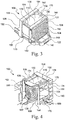
- FIG. 3 shows a back perspective view of a fan assembly 100 having an integrated fan module 102 with an integrated louver module 110.
- FIG. 4 shows a front perspective view of the fan assembly 100.
- FIG. 5 is a perspective view of the louver module 110 separated from the fan module 102. Like elements are labeled with identical element numbers throughout FIGs. 3-5 .
- the fan module 102 includes a carrier structure 120.
- the carrier structure 120 includes a handle 122 that allows the fan module 102 to be easily removed from an electronic device, such as a server or network switch.
- the carrier structure 120 includes a rear end 124 that vents air flow and an opposite front air intake end 126 that draws in air flow.
- the carrier structure 120 includes a motor casing 130, that is located between the intake end 126 and the rear end 124.
- the motor casing 130 holds a motor 136 and a fan 104.
- the fan has a series of fan blades that is propelled by the motor 136.
- the motor 136 is powered via cable connectors that may be attached to a power source, such as a power supply unit on a board of the electronic device. Power supply signals to the motor 136 cause the fan 104 to rotate. Fan 104 rotation draws air in from the intake end 126 and pushes air out through the rear end 124.
- the carrier structure 120 includes a front frame 132 and a rear frame 134.
- the front frame 132 and the rear frame 134 are on opposite sides of the motor casing 130.
- the rear frame 134 includes side members 140 and 142.
- the side members 140 and 142 are attached to the handle 122.
- the side members 140 and 142 are joined by a top member 144, and a bottom member 146.
- the rear frame 134 includes a grill 148 that serves to prevent particles from entering the carrier structure 120.
- the side members 140 and 142 and the top and bottom members 144 and 146 form the louver module 110.
- the front frame 132 includes side members 150 and 152.
- the side members 150 and 152 are joined by a top member 154 and a bottom member 156.
- the side members 150 and 152, the top member 154, and the bottom member 156 form a front surface 158 that defines an intake opening 160.
- the intake opening 160 includes a webbing pattern 162 that allows air flow to be directed toward the fan propelled by the motor in the motor casing 130.
- a series of rods 170 are employed to attach the front frame 132 to the rear frame 134 (in FIG. 3 ).
- the rods 170 span the length of the motor casing 130.
- the louver module 110 is integrated in the rear frame 134.
- the rear frame 134 is defined by the top member 144, the bottom member 146, and the side members 140 and 142.
- One side of rear frame 134 is closed by the grill 148 that is attached to one side of the side members 140 and 142, and the top and bottom members 144 and 146.
- the top member 144 and the bottom member 146 each have respective interior surfaces 220 and 222.
- the opposite side of the members 140, 142, 144, and 146 form a contact surface 230, that is defined by four corner supports 232, 234, 236, and 238 at the junctions of the side members 140 and 142, top member 144, and bottom member 146.
- the members 140, 142, 144, and 146 define an opening that is roughly the same cross sectional area as the output area from the fan in the motor casing 130.
- the contact surface 230 of the members 140, 142, 144, and 146 are flush with the motor casing 130 and form a seal to prevent air flow from leaking out of the side of the fan assembly 100.
- the four corner supports 232, 234, 236, and 238, each may include a hole 240 that allows the rods 170 to be inserted and join the rear frame 134 with the front frame 132.
- the front frame 132 has similar holes to accommodate the rods 170.
- the holes 240 may have screw threads that allow the rods 170 be screwed into the holes and thus hold the front frame 132 in relation to the rear frame 134.
- a series of slats 250 are rotatably attached between the interior surfaces 220 and 222 of the top and bottom members 144 and 146.
- Each of the slats 250 are mounted similar to an impeller blade.
- the slats 250 may be rotated between an open position (as shown in FIG. 6 ) and a closed position (as shown in FIG. 7 ).
- the open position is where the slats 250 are parallel to the side members 140 and 142, thereby allowing air flow between the slats 250 (as shown in FIG. 5 ).
- the closed position is where the slats 250 are perpendicular to the side members 140 and 142, thereby blocking air flow through the fan assembly 100.
- the fan assembly 100 When the fan assembly 100 is functioning, air flow is drawn from the front air intake end 126, through the motor casing 130, and through the louver module 110. The air flow forces the slats 250 into the open position.
- the fan assembly 100 fails, reverse air flow causes air flow in the direction from the rear end 124 to the louver module 110. This reverse air flow causes the slats 250 to swing to the closed position and thereby prevents air flow through the rest of the fan module 102.
- the slats are vertically oriented, but it is to be understood that the principles herein may apply horizontally oriented slats that would be mounted between the side members 140 and 142.
- the above example is based on the concept of a louver impeller assembled to lock onto an existing fan carrier structure 120.
- the impeller mechanism (slats 250 in FIGs. 6-7 ) is designed in either a vertical or horizontal direction, which can be blown open by the fan 104 driving air. Once fan 104 failure occurs, the pressure difference between the fan 104 inlet and outlet will force the impeller of the louver module 110 be closed automatically.
- the integrated nature of the louver module 110 in the fan assembly 100 prevents reverse air flow by eliminating any gaps between the louver 110 and the fan module 102.
- One benefit of present example fan system is to eliminate reverse air flow, which is blocked by the louver module 110. The elimination of reverse air flow thus allows maximum air flow through other fans.
- louver frame has slats inside and is a separate component. Such a louver must be located in front of a fan module to block reverse air flow. As explained above, a separate louver frame is no longer needed as the slats are integrated inside the carrier structure 120. The above described principles may there simplify the louver design as integrated with the fan itself.
Landscapes
- Engineering & Computer Science (AREA)
- General Engineering & Computer Science (AREA)
- Mechanical Engineering (AREA)
- Physics & Mathematics (AREA)
- Thermal Sciences (AREA)
- Microelectronics & Electronic Packaging (AREA)
- Chemical & Material Sciences (AREA)
- Combustion & Propulsion (AREA)
- Computer Hardware Design (AREA)
- Cooling Or The Like Of Electrical Apparatus (AREA)
- Structures Of Non-Positive Displacement Pumps (AREA)
Abstract
Description
- The present disclosure relates generally to a fan system. More particularly, aspects of this disclosure relate to an integrated fan module that incorporates a louver to prevent reverse fan flow.
- Electronic devices, such as servers, include numerous electronic components that are powered to a common power supply. Servers generate an enormous amount of heat due to the operation of internal electronic devices such as controllers, processors, and memory. Overheating from the inefficient removal of such heat has the potential to shut down or impede the operation of such devices. Thus, servers are designed to rely on air flow through the interior of the device to carry away heat generated from electronic components. Servers often include various heat sinks that are attached to the electronic components such as processing units. Heat sinks are typically composed of thermally conductive material. Heat sinks absorb the heat from the electronic components, thus transferring the heat away from the components. The heat from heat sinks must be vented away from the server. Air flow to vent away such heat is often generated by a fan system. The generated air flow thus carries collected heat away from the components and the heat sink. A good thermal design can assure the smallest fan power with limited air flow is sufficient to cool a fixed server or switch system power level. Thus, air flow can pass through hot electric components in the device without any reverse air flow because the internal layout effectively channels the air flow.
- A typical fan system will include multiple fans. Such fans may be grouped together in a fan wall to provide maximum cooling. Further, additional fans provide redundancy that allows for the operation of the server even if one of the fans in the fan wall fails. However, one issue with grouping fans occurs when a single fan fails. Reverse air flow occurs because the failed fan creates a low pressure area.
FIG. 1 is a perspective view of aserver 10 that includesvarious components 12 that illustrates the reverse flow problem. Thecomponents 12 are cooled by afan wall 14. Thefan wall 14 in this example includesseparate fans fan 22 has failed and thus stops providing air flow. The lack of air flow from thefan 22 creates a low pressure area because theremaining fans non-functioning fan 22. The low pressure area creates reverse air flow as shown byarrows 30. The reverse air flow will reduce overall system air flow therefore cooling of components in theserver 10 will be compromised. - In order to solve this reverse flow issue, a louver device has been installed in front of each fan module.
FIG. 2 shows such aserver 50 that includes variouselectronic components 52. Thecomponents 52 are cooled by afan wall 54. Thefan wall 54 includesseparate fans fans front fan louver fan louvers fans - Thus, there is a need for a fan system that uses a louver to effectively prevent reverse air flow when a fan fails. There is also a need for a fan system that allows a louver frame to be easily mated to a fan module. There is a further need for an integrated fan system that blocks any leaking reverse air flow when a louver is activated.
- One disclosed example is a fan assembly. The assembly has a fan module including an intake end, a motor casing, and a motor propelling a fan, and a vent end. A louver module has a plurality of slats having an open position to allow air flow, and a closed position to block air flow. The louver module is coupled to the motor casing to provide a seal between the louver module and the motor casing.
- Another example is a fan louver module for connection with a motor casing of a fan. The fan louver module includes a frame having side walls and top and bottom walls. A plurality of slats is mounted in the frame. The plurality of slats have an open position to allow air flow though the frame, and a closed position to block air flow through the frame. The frame has approximately the same cross section area as the motor casing of the fan. The frame is attachable to the motor casing to provide a seal between the motor casing and the frame.
- The above summary is not intended to represent each embodiment or every aspect of the present disclosure. Rather, the foregoing summary merely provides an example of some of the novel aspects and features set forth herein. The above features and advantages, and other features and advantages of the present disclosure, will be readily apparent from the following detailed description of representative embodiments and modes for carrying out the present invention, when taken in connection with the accompanying drawings and the appended claims.
- The disclosure will be better understood from the following description of exemplary embodiments together with reference to the accompanying drawings, in which:
-
FIG. 1 is a prior art server having a series of fans showing the problem of reverse air flow; -
FIG. 2 is another prior art server having a series of louvers in front of fans, that attempts to addresses the problem of reverse air flow; -
FIG. 3 is a perspective back view of a fan module with an integrated louver; -
FIG. 4 is a perspective front view of the fan module and louver structure inFIG. 3 ; -
FIG. 5 is a perspective rear view of the integrated louver module inFIG. 3 ; -
FIG. 6 is a perspective view of the louver module inFIG. 3 with the louver open; and -
FIG. 7 is a perspective view of the louver module inFIG. 3 with the louver closed. - The present disclosure is susceptible to various modifications and alternative forms. Some representative embodiments have been shown by way of example in the drawings and will be described in detail herein. It should be understood, however, that the invention is not intended to be limited to the particular forms disclosed. Rather, the disclosure is to cover all modifications, equivalents, and alternatives falling within the spirit and scope of the invention as defined by the appended claims.
- The present inventions can be embodied in many different forms. Representative embodiments are shown in the drawings, and will herein be described in detail. The present disclosure is an example or illustration of the principles of the present disclosure, and is not intended to limit the broad aspects of the disclosure to the embodiments illustrated. To that extent, elements, and limitations that are disclosed, for example, in the Abstract, Summary, and Detailed Description sections, but not explicitly set forth in the claims, should not be incorporated into the claims, singly or collectively, by implication, inference, or otherwise. For purposes of the present detailed description, unless specifically disclaimed, the singular includes the plural and vice versa; and the word "including" means "including without limitation." Moreover, words of approximation, such as "about," "almost," "substantially," "approximately," and the like, can be used herein to mean "at," "near," or "nearly at," or "within 3-5% of," or "within acceptable manufacturing tolerances," or any logical combination thereof, for example.
-
FIG. 3 shows a back perspective view of afan assembly 100 having anintegrated fan module 102 with anintegrated louver module 110.FIG. 4 shows a front perspective view of thefan assembly 100.FIG. 5 is a perspective view of thelouver module 110 separated from thefan module 102. Like elements are labeled with identical element numbers throughoutFIGs. 3-5 . - As shown in
FIG. 3 , thefan module 102 includes acarrier structure 120. Thecarrier structure 120 includes ahandle 122 that allows thefan module 102 to be easily removed from an electronic device, such as a server or network switch. Thecarrier structure 120 includes arear end 124 that vents air flow and an opposite frontair intake end 126 that draws in air flow. Thecarrier structure 120 includes amotor casing 130, that is located between theintake end 126 and therear end 124. Themotor casing 130 holds amotor 136 and afan 104. The fan has a series of fan blades that is propelled by themotor 136. Themotor 136 is powered via cable connectors that may be attached to a power source, such as a power supply unit on a board of the electronic device. Power supply signals to themotor 136 cause thefan 104 to rotate.Fan 104 rotation draws air in from theintake end 126 and pushes air out through therear end 124. - The
carrier structure 120 includes afront frame 132 and arear frame 134. Thefront frame 132 and therear frame 134 are on opposite sides of themotor casing 130. Therear frame 134 includesside members side members handle 122. Theside members top member 144, and abottom member 146. Therear frame 134 includes agrill 148 that serves to prevent particles from entering thecarrier structure 120. As will be explained below, theside members bottom members louver module 110. - As shown in
FIG. 4 , thefront frame 132 includesside members side members top member 154 and abottom member 156. Theside members top member 154, and thebottom member 156, form afront surface 158 that defines anintake opening 160. Theintake opening 160 includes awebbing pattern 162 that allows air flow to be directed toward the fan propelled by the motor in themotor casing 130. A series ofrods 170 are employed to attach thefront frame 132 to the rear frame 134 (inFIG. 3 ). Therods 170 span the length of themotor casing 130. - As shown in
FIG. 5 , thelouver module 110 is integrated in therear frame 134. Therear frame 134 is defined by thetop member 144, thebottom member 146, and theside members rear frame 134 is closed by thegrill 148 that is attached to one side of theside members bottom members top member 144 and thebottom member 146 each have respectiveinterior surfaces members contact surface 230, that is defined by four corner supports 232, 234, 236, and 238 at the junctions of theside members top member 144, andbottom member 146. - The
members motor casing 130. When therear frame 134 andintegrated louver module 110 is attached to the motor casing 130 (as shown inFIGs. 3 and 4 ), thecontact surface 230 of themembers motor casing 130 and form a seal to prevent air flow from leaking out of the side of thefan assembly 100. The four corner supports 232, 234, 236, and 238, each may include ahole 240 that allows therods 170 to be inserted and join therear frame 134 with thefront frame 132. Thefront frame 132 has similar holes to accommodate therods 170. Theholes 240 may have screw threads that allow therods 170 be screwed into the holes and thus hold thefront frame 132 in relation to therear frame 134. - As show in
FIGs. 6 and 7 , a series ofslats 250 are rotatably attached between theinterior surfaces bottom members slats 250 are mounted similar to an impeller blade. Theslats 250 may be rotated between an open position (as shown inFIG. 6 ) and a closed position (as shown inFIG. 7 ). The open position is where theslats 250 are parallel to theside members FIG. 5 ). The closed position is where theslats 250 are perpendicular to theside members fan assembly 100. When thefan assembly 100 is functioning, air flow is drawn from the frontair intake end 126, through themotor casing 130, and through thelouver module 110. The air flow forces theslats 250 into the open position. When thefan assembly 100 fails, reverse air flow causes air flow in the direction from therear end 124 to thelouver module 110. This reverse air flow causes theslats 250 to swing to the closed position and thereby prevents air flow through the rest of thefan module 102. In this example, the slats are vertically oriented, but it is to be understood that the principles herein may apply horizontally oriented slats that would be mounted between theside members - The above example is based on the concept of a louver impeller assembled to lock onto an existing
fan carrier structure 120. The impeller mechanism (slats 250 inFIGs. 6-7 ) is designed in either a vertical or horizontal direction, which can be blown open by thefan 104 driving air. Oncefan 104 failure occurs, the pressure difference between thefan 104 inlet and outlet will force the impeller of thelouver module 110 be closed automatically. The integrated nature of thelouver module 110 in thefan assembly 100 prevents reverse air flow by eliminating any gaps between thelouver 110 and thefan module 102. One benefit of present example fan system is to eliminate reverse air flow, which is blocked by thelouver module 110. The elimination of reverse air flow thus allows maximum air flow through other fans. The principles above can eliminate the reverse air flow and simplify fan louver design. In a traditional design, a louver frame has slats inside and is a separate component. Such a louver must be located in front of a fan module to block reverse air flow. As explained above, a separate louver frame is no longer needed as the slats are integrated inside thecarrier structure 120. The above described principles may there simplify the louver design as integrated with the fan itself. - Although the invention has been illustrated and described with respect to one or more implementations, equivalent alterations, and modifications will occur or be known to others skilled in the art upon the reading and understanding of this specification and the annexed drawings. In addition, while a particular feature of the invention may have been disclosed with respect to only one of several implementations, such feature may be combined with one or more other features of the other implementations as may be desired and advantageous for any given or particular application.
Claims (12)
- A integrated fan assembly (100), comprising:a fan module (102) including an intake end (126), a motor casing (130), and a motor (136) propelling a fan (104); anda louver module (110) having a plurality of slats (250) having an open position (Fig. 6) to allow air flow and a closed position (Fig. 7) to block air flow, wherein the louver module (110) is coupled to the motor casing (130) to provide a seal between the louver module (110) and the motor casing (130).
- The assembly (100) of claim 1, wherein the louver module (110) includes a rear frame (134) having a handle (122).
- The assembly (100) of claim 1, wherein the plurality of slats (250) is forced to the closed position (Fig. 7) when air flow occurs from the louver module (110) to the intake end (126).
- The assembly (100) of claim 1, further comprising a front frame (132) coupled to the motor casing (130).
- The assembly (100) of claim 1, further comprising a grill (148) attached to the louver module (110) for transmission of air flow.
- The assembly (100) of claim 1, wherein the plurality of slats (250) is vertically oriented and rotatably attached to top (144, 154) and bottom members (146, 156) of the louver module (110).
- The assembly (100) of claim 1, wherein the plurality of slats (250) is horizontally oriented and rotatably attached to side members (140, 142, 150, 152) of the louver module (110).
- A fan louver module (110) for connection with a motor casing (130) of a fan (104), the fan louver module (110) comprising:a frame (132, 134) having side walls (140, 142, 150, 152)and top (144, 154) and bottom walls (146, 156); anda plurality of slats (250)mounted in the frame, the plurality of slats (250) having an open position (Fig. 6) to allow air flow though the frame (132, 134) and a closed position (Fig. 7) blocking air flow through the frame (132, 134);wherein the frame (132, 134) has approximately the same cross section area as a front end of the motor casing (130), and wherein the frame (132, 134) is attachable to the motor casing (130) of the fan (104) to provide a seal between the motor casing (130) and the frame (132, 134).
- The fan louver module (110) of claim 8, wherein the plurality of slats (250) is forced to the closed position (Fig. 7) when air flow occurs from the frame (132, 134) to the motor casing (130).
- The fan louver module (110) of claim 8, wherein the frame (132, 134) of the louver module (110) includes a first attachment point that may be joined with a corresponding attachment point on a front frame (132) of the fan (104).
- The fan louver module (110) of claim 8, wherein the plurality of slats (250) is vertically oriented and rotatably attached to top (144, 154) and bottom members (146, 156) of the frame (132, 134).
- The fan louver module (110) of claim 8, wherein the plurality of slats (250) is horizontally oriented and rotatably attached to the side members (140, 142, 150, 152) of the frame (132, 134).
Applications Claiming Priority (2)
| Application Number | Priority Date | Filing Date | Title |
|---|---|---|---|
| US201862623714P | 2018-01-30 | 2018-01-30 | |
| US15/972,795 US20190234647A1 (en) | 2018-01-30 | 2018-05-07 | Louver integrated design for fan module |
Publications (1)
| Publication Number | Publication Date |
|---|---|
| EP3517786A1 true EP3517786A1 (en) | 2019-07-31 |
Family
ID=63667749
Family Applications (1)
| Application Number | Title | Priority Date | Filing Date |
|---|---|---|---|
| EP18195655.8A Withdrawn EP3517786A1 (en) | 2018-01-30 | 2018-09-20 | Louver integrated design for fan module |
Country Status (5)
| Country | Link |
|---|---|
| US (1) | US20190234647A1 (en) |
| EP (1) | EP3517786A1 (en) |
| JP (1) | JP2019132268A (en) |
| CN (1) | CN110094369A (en) |
| TW (1) | TW201932719A (en) |
Cited By (1)
| Publication number | Priority date | Publication date | Assignee | Title |
|---|---|---|---|---|
| US20240397661A1 (en) * | 2023-05-24 | 2024-11-28 | Nanning Fulian Fugui Precision Industrial Co., Ltd. | Fan module and electronic device |
Families Citing this family (3)
| Publication number | Priority date | Publication date | Assignee | Title |
|---|---|---|---|---|
| IL301215B2 (en) | 2020-09-21 | 2026-03-01 | Premier Specialty Brands LLC | Integrated kamado-style grill and smoker |
| US11125438B1 (en) | 2020-11-20 | 2021-09-21 | Spider Grills, Llc | System and method for bimodal air control in a kettle-style grill |
| US12480660B2 (en) | 2020-11-20 | 2025-11-25 | Spider Grills, Llc | System and method for forced air control in a kamado-style cooker |
Citations (5)
| Publication number | Priority date | Publication date | Assignee | Title |
|---|---|---|---|---|
| JPS53156373U (en) * | 1977-05-16 | 1978-12-08 | ||
| US20120138262A1 (en) * | 2010-12-06 | 2012-06-07 | Hon Hai Precision Industry Co., Ltd. | Fan assembly |
| US20130017076A1 (en) * | 2011-07-14 | 2013-01-17 | Hon Hai Precision Industry Co., Ltd. | Fan assembly |
| US20130023199A1 (en) * | 2011-07-18 | 2013-01-24 | Hon Hai Precision Industry Co., Ltd. | Fan assembly |
| GB2508423A (en) * | 2012-11-30 | 2014-06-04 | Greenwood Air Man Ltd | A fan installed in a building component |
Family Cites Families (18)
| Publication number | Priority date | Publication date | Assignee | Title |
|---|---|---|---|---|
| US2037857A (en) * | 1935-01-24 | 1936-04-21 | Wilfred R Fox | Automobile heater |
| JPH1122698A (en) * | 1997-07-01 | 1999-01-26 | Sony Corp | Fan device and disk array device using the same |
| US6115250A (en) * | 1998-01-20 | 2000-09-05 | Dell Usa, Lp | Computer and an assembly and method for cooling a computer |
| TWM284030U (en) * | 2004-04-06 | 2005-12-21 | Tatung Co | Frame for fixing a heat-dissipating fan |
| US7416481B2 (en) * | 2006-03-06 | 2008-08-26 | International Business Machines Corporation | Blower exhaust backflow damper |
| TWI322659B (en) * | 2006-12-18 | 2010-03-21 | Delta Electronics Inc | Fan and fan frame having window structure thereof |
| CN200997637Y (en) * | 2006-12-29 | 2007-12-26 | 艾默生网络能源有限公司 | Radiating fan of telecommunication power-supply module |
| CN201216045Y (en) * | 2008-07-01 | 2009-04-01 | 华为技术有限公司 | Backflow device and fan module |
| JP4615044B2 (en) * | 2008-11-12 | 2011-01-19 | 富士通株式会社 | Air cooling fan unit |
| US20110028081A1 (en) * | 2009-07-29 | 2011-02-03 | Huntair, Inc. | Back draft damper |
| TWI420024B (en) * | 2010-12-13 | 2013-12-21 | 泰達電子公司 | Reflux limiting device and fan unit |
| CN102968164A (en) * | 2011-09-01 | 2013-03-13 | 鸿富锦精密工业(深圳)有限公司 | Cooling system with backflow prevention function |
| CN202348782U (en) * | 2011-09-30 | 2012-07-25 | 百度在线网络技术(北京)有限公司 | Anti-backflow radiating device |
| TWI505767B (en) * | 2013-01-31 | 2015-10-21 | Hon Hai Prec Ind Co Ltd | Heat dissipating device |
| CN203867946U (en) * | 2013-09-26 | 2014-10-08 | 环旭电子股份有限公司 | Fan device capable of preventing air backflow |
| CN105275356B (en) * | 2014-07-17 | 2017-04-19 | 奇鋐科技股份有限公司 | Fan shutter device |
| US9861010B2 (en) * | 2014-09-29 | 2018-01-02 | International Business Machines Corporation | Protective louver assembly for air-moving assembly |
| US20180077819A1 (en) * | 2016-09-14 | 2018-03-15 | Switch, Ltd. | Ventilation and air flow control |
-
2018
- 2018-05-07 US US15/972,795 patent/US20190234647A1/en not_active Abandoned
- 2018-08-14 TW TW107128347A patent/TW201932719A/en unknown
- 2018-09-04 CN CN201811024465.5A patent/CN110094369A/en active Pending
- 2018-09-20 EP EP18195655.8A patent/EP3517786A1/en not_active Withdrawn
- 2018-11-15 JP JP2018214553A patent/JP2019132268A/en active Pending
Patent Citations (5)
| Publication number | Priority date | Publication date | Assignee | Title |
|---|---|---|---|---|
| JPS53156373U (en) * | 1977-05-16 | 1978-12-08 | ||
| US20120138262A1 (en) * | 2010-12-06 | 2012-06-07 | Hon Hai Precision Industry Co., Ltd. | Fan assembly |
| US20130017076A1 (en) * | 2011-07-14 | 2013-01-17 | Hon Hai Precision Industry Co., Ltd. | Fan assembly |
| US20130023199A1 (en) * | 2011-07-18 | 2013-01-24 | Hon Hai Precision Industry Co., Ltd. | Fan assembly |
| GB2508423A (en) * | 2012-11-30 | 2014-06-04 | Greenwood Air Man Ltd | A fan installed in a building component |
Cited By (2)
| Publication number | Priority date | Publication date | Assignee | Title |
|---|---|---|---|---|
| US20240397661A1 (en) * | 2023-05-24 | 2024-11-28 | Nanning Fulian Fugui Precision Industrial Co., Ltd. | Fan module and electronic device |
| US12550287B2 (en) * | 2023-05-24 | 2026-02-10 | Nanning Fulian Fugui Precision Industrial Co., Ltd. | Fan module and electronic device |
Also Published As
| Publication number | Publication date |
|---|---|
| US20190234647A1 (en) | 2019-08-01 |
| TW201932719A (en) | 2019-08-16 |
| JP2019132268A (en) | 2019-08-08 |
| CN110094369A (en) | 2019-08-06 |
Similar Documents
| Publication | Publication Date | Title |
|---|---|---|
| CN114630558B (en) | Heat dissipation system, power supply system and charging pile | |
| US8450889B2 (en) | Method and structure for cooling an electric motor | |
| US20190234647A1 (en) | Louver integrated design for fan module | |
| US7254022B2 (en) | Cooling system for equipment and network cabinets and method for cooling equipment and network cabinets | |
| US8503178B2 (en) | Heat exchange device and closed-type electronic apparatus using the same | |
| US7120019B2 (en) | Coaxial air ducts and fans for cooling and electronic component | |
| JP6214462B2 (en) | Air conditioner outdoor unit | |
| KR101589027B1 (en) | Outdoor unit of air conditioner | |
| US9332679B2 (en) | Fan assembly for rack optimized server computers | |
| TWI505767B (en) | Heat dissipating device | |
| US7755889B2 (en) | Air Manifold for electronic module enclosure | |
| US20020015287A1 (en) | Cooling system and method for a high density electronics enclosure | |
| TW201422130A (en) | Container data center and cabinet thereof | |
| JP7718768B2 (en) | Electrical control box, air conditioner outdoor unit and air conditioner | |
| WO2018153261A1 (en) | Tube tower and base station | |
| JP2011058420A (en) | Fan apparatus, electronic device, and fan-attached case | |
| US10542634B2 (en) | Fan reconfiguration and displacement due to a failed or failing fan | |
| US20050088818A1 (en) | Backflow-preventive fan module | |
| US6529376B2 (en) | System processor heat dissipation | |
| CN104781929B (en) | Thermoelectric assembly | |
| CN114096466B (en) | Unmanned aerial vehicle | |
| KR101912684B1 (en) | Cooling system for EMP rack | |
| JP3214442B2 (en) | Cold heat source unit | |
| CN102548347A (en) | Electronic equipment and heat radiation device thereof | |
| CN117940672B (en) | Cooling device with fan and housing with such a cooling device |
Legal Events
| Date | Code | Title | Description |
|---|---|---|---|
| PUAI | Public reference made under article 153(3) epc to a published international application that has entered the european phase |
Free format text: ORIGINAL CODE: 0009012 |
|
| STAA | Information on the status of an ep patent application or granted ep patent |
Free format text: STATUS: THE APPLICATION HAS BEEN PUBLISHED |
|
| AK | Designated contracting states |
Kind code of ref document: A1 Designated state(s): AL AT BE BG CH CY CZ DE DK EE ES FI FR GB GR HR HU IE IS IT LI LT LU LV MC MK MT NL NO PL PT RO RS SE SI SK SM TR |
|
| AX | Request for extension of the european patent |
Extension state: BA ME |
|
| STAA | Information on the status of an ep patent application or granted ep patent |
Free format text: STATUS: REQUEST FOR EXAMINATION WAS MADE |
|
| 17P | Request for examination filed |
Effective date: 20190926 |
|
| RBV | Designated contracting states (corrected) |
Designated state(s): AL AT BE BG CH CY CZ DE DK EE ES FI FR GB GR HR HU IE IS IT LI LT LU LV MC MK MT NL NO PL PT RO RS SE SI SK SM TR |
|
| STAA | Information on the status of an ep patent application or granted ep patent |
Free format text: STATUS: EXAMINATION IS IN PROGRESS |
|
| 17Q | First examination report despatched |
Effective date: 20220512 |
|
| STAA | Information on the status of an ep patent application or granted ep patent |
Free format text: STATUS: THE APPLICATION IS DEEMED TO BE WITHDRAWN |
|
| 18D | Application deemed to be withdrawn |
Effective date: 20230503 |