EP3517512A1 - Cover glass and display using same - Google Patents
Cover glass and display using same Download PDFInfo
- Publication number
- EP3517512A1 EP3517512A1 EP17852777.6A EP17852777A EP3517512A1 EP 3517512 A1 EP3517512 A1 EP 3517512A1 EP 17852777 A EP17852777 A EP 17852777A EP 3517512 A1 EP3517512 A1 EP 3517512A1
- Authority
- EP
- European Patent Office
- Prior art keywords
- layer
- acoustic impedance
- glass
- cover glass
- viscoelastic
- Prior art date
- Legal status (The legal status is an assumption and is not a legal conclusion. Google has not performed a legal analysis and makes no representation as to the accuracy of the status listed.)
- Granted
Links
Images


Classifications
-
- C—CHEMISTRY; METALLURGY
- C03—GLASS; MINERAL OR SLAG WOOL
- C03C—CHEMICAL COMPOSITION OF GLASSES, GLAZES OR VITREOUS ENAMELS; SURFACE TREATMENT OF GLASS; SURFACE TREATMENT OF FIBRES OR FILAMENTS MADE FROM GLASS, MINERALS OR SLAGS; JOINING GLASS TO GLASS OR OTHER MATERIALS
- C03C17/00—Surface treatment of glass, not in the form of fibres or filaments, by coating
- C03C17/28—Surface treatment of glass, not in the form of fibres or filaments, by coating with organic material
- C03C17/32—Surface treatment of glass, not in the form of fibres or filaments, by coating with organic material with synthetic or natural resins
-
- B—PERFORMING OPERATIONS; TRANSPORTING
- B32—LAYERED PRODUCTS
- B32B—LAYERED PRODUCTS, i.e. PRODUCTS BUILT-UP OF STRATA OF FLAT OR NON-FLAT, e.g. CELLULAR OR HONEYCOMB, FORM
- B32B17/00—Layered products essentially comprising sheet glass, or glass, slag, or like fibres
- B32B17/06—Layered products essentially comprising sheet glass, or glass, slag, or like fibres comprising glass as the main or only constituent of a layer, next to another layer of a specific material
- B32B17/08—Layered products essentially comprising sheet glass, or glass, slag, or like fibres comprising glass as the main or only constituent of a layer, next to another layer of a specific material of cellulosic plastic substance or gelatin
-
- B—PERFORMING OPERATIONS; TRANSPORTING
- B32—LAYERED PRODUCTS
- B32B—LAYERED PRODUCTS, i.e. PRODUCTS BUILT-UP OF STRATA OF FLAT OR NON-FLAT, e.g. CELLULAR OR HONEYCOMB, FORM
- B32B17/00—Layered products essentially comprising sheet glass, or glass, slag, or like fibres
- B32B17/06—Layered products essentially comprising sheet glass, or glass, slag, or like fibres comprising glass as the main or only constituent of a layer, next to another layer of a specific material
- B32B17/10—Layered products essentially comprising sheet glass, or glass, slag, or like fibres comprising glass as the main or only constituent of a layer, next to another layer of a specific material of synthetic resin
-
- B—PERFORMING OPERATIONS; TRANSPORTING
- B32—LAYERED PRODUCTS
- B32B—LAYERED PRODUCTS, i.e. PRODUCTS BUILT-UP OF STRATA OF FLAT OR NON-FLAT, e.g. CELLULAR OR HONEYCOMB, FORM
- B32B27/00—Layered products comprising a layer of synthetic resin
- B32B27/28—Layered products comprising a layer of synthetic resin comprising synthetic resins not wholly covered by any one of the sub-groups B32B27/30 - B32B27/42
- B32B27/281—Layered products comprising a layer of synthetic resin comprising synthetic resins not wholly covered by any one of the sub-groups B32B27/30 - B32B27/42 comprising polyimides
-
- B—PERFORMING OPERATIONS; TRANSPORTING
- B32—LAYERED PRODUCTS
- B32B—LAYERED PRODUCTS, i.e. PRODUCTS BUILT-UP OF STRATA OF FLAT OR NON-FLAT, e.g. CELLULAR OR HONEYCOMB, FORM
- B32B27/00—Layered products comprising a layer of synthetic resin
- B32B27/30—Layered products comprising a layer of synthetic resin comprising vinyl (co)polymers; comprising acrylic (co)polymers
- B32B27/308—Layered products comprising a layer of synthetic resin comprising vinyl (co)polymers; comprising acrylic (co)polymers comprising acrylic (co)polymers
-
- B—PERFORMING OPERATIONS; TRANSPORTING
- B32—LAYERED PRODUCTS
- B32B—LAYERED PRODUCTS, i.e. PRODUCTS BUILT-UP OF STRATA OF FLAT OR NON-FLAT, e.g. CELLULAR OR HONEYCOMB, FORM
- B32B27/00—Layered products comprising a layer of synthetic resin
- B32B27/32—Layered products comprising a layer of synthetic resin comprising polyolefins
-
- B—PERFORMING OPERATIONS; TRANSPORTING
- B32—LAYERED PRODUCTS
- B32B—LAYERED PRODUCTS, i.e. PRODUCTS BUILT-UP OF STRATA OF FLAT OR NON-FLAT, e.g. CELLULAR OR HONEYCOMB, FORM
- B32B27/00—Layered products comprising a layer of synthetic resin
- B32B27/34—Layered products comprising a layer of synthetic resin comprising polyamides
-
- B—PERFORMING OPERATIONS; TRANSPORTING
- B32—LAYERED PRODUCTS
- B32B—LAYERED PRODUCTS, i.e. PRODUCTS BUILT-UP OF STRATA OF FLAT OR NON-FLAT, e.g. CELLULAR OR HONEYCOMB, FORM
- B32B27/00—Layered products comprising a layer of synthetic resin
- B32B27/36—Layered products comprising a layer of synthetic resin comprising polyesters
-
- B—PERFORMING OPERATIONS; TRANSPORTING
- B32—LAYERED PRODUCTS
- B32B—LAYERED PRODUCTS, i.e. PRODUCTS BUILT-UP OF STRATA OF FLAT OR NON-FLAT, e.g. CELLULAR OR HONEYCOMB, FORM
- B32B27/00—Layered products comprising a layer of synthetic resin
- B32B27/36—Layered products comprising a layer of synthetic resin comprising polyesters
- B32B27/365—Layered products comprising a layer of synthetic resin comprising polyesters comprising polycarbonates
-
- B—PERFORMING OPERATIONS; TRANSPORTING
- B32—LAYERED PRODUCTS
- B32B—LAYERED PRODUCTS, i.e. PRODUCTS BUILT-UP OF STRATA OF FLAT OR NON-FLAT, e.g. CELLULAR OR HONEYCOMB, FORM
- B32B7/00—Layered products characterised by the relation between layers; Layered products characterised by the relative orientation of features between layers, or by the relative values of a measurable parameter between layers, i.e. products comprising layers having different physical, chemical or physicochemical properties; Layered products characterised by the interconnection of layers
- B32B7/04—Interconnection of layers
- B32B7/12—Interconnection of layers using interposed adhesives or interposed materials with bonding properties
-
- C—CHEMISTRY; METALLURGY
- C03—GLASS; MINERAL OR SLAG WOOL
- C03C—CHEMICAL COMPOSITION OF GLASSES, GLAZES OR VITREOUS ENAMELS; SURFACE TREATMENT OF GLASS; SURFACE TREATMENT OF FIBRES OR FILAMENTS MADE FROM GLASS, MINERALS OR SLAGS; JOINING GLASS TO GLASS OR OTHER MATERIALS
- C03C17/00—Surface treatment of glass, not in the form of fibres or filaments, by coating
- C03C17/34—Surface treatment of glass, not in the form of fibres or filaments, by coating with at least two coatings having different compositions
- C03C17/3405—Surface treatment of glass, not in the form of fibres or filaments, by coating with at least two coatings having different compositions with at least two coatings of organic materials
-
- G—PHYSICS
- G06—COMPUTING OR CALCULATING; COUNTING
- G06F—ELECTRIC DIGITAL DATA PROCESSING
- G06F1/00—Details not covered by groups G06F3/00 - G06F13/00 and G06F21/00
- G06F1/16—Constructional details or arrangements
- G06F1/18—Packaging or power distribution
- G06F1/181—Enclosures
-
- G—PHYSICS
- G09—EDUCATION; CRYPTOGRAPHY; DISPLAY; ADVERTISING; SEALS
- G09F—DISPLAYING; ADVERTISING; SIGNS; LABELS OR NAME-PLATES; SEALS
- G09F9/00—Indicating arrangements for variable information in which the information is built-up on a support by selection or combination of individual elements
-
- B—PERFORMING OPERATIONS; TRANSPORTING
- B32—LAYERED PRODUCTS
- B32B—LAYERED PRODUCTS, i.e. PRODUCTS BUILT-UP OF STRATA OF FLAT OR NON-FLAT, e.g. CELLULAR OR HONEYCOMB, FORM
- B32B2255/00—Coating on the layer surface
- B32B2255/26—Polymeric coating
-
- B—PERFORMING OPERATIONS; TRANSPORTING
- B32—LAYERED PRODUCTS
- B32B—LAYERED PRODUCTS, i.e. PRODUCTS BUILT-UP OF STRATA OF FLAT OR NON-FLAT, e.g. CELLULAR OR HONEYCOMB, FORM
- B32B2307/00—Properties of the layers or laminate
- B32B2307/10—Properties of the layers or laminate having particular acoustical properties
-
- B—PERFORMING OPERATIONS; TRANSPORTING
- B32—LAYERED PRODUCTS
- B32B—LAYERED PRODUCTS, i.e. PRODUCTS BUILT-UP OF STRATA OF FLAT OR NON-FLAT, e.g. CELLULAR OR HONEYCOMB, FORM
- B32B2307/00—Properties of the layers or laminate
- B32B2307/40—Properties of the layers or laminate having particular optical properties
- B32B2307/412—Transparent
-
- B—PERFORMING OPERATIONS; TRANSPORTING
- B32—LAYERED PRODUCTS
- B32B—LAYERED PRODUCTS, i.e. PRODUCTS BUILT-UP OF STRATA OF FLAT OR NON-FLAT, e.g. CELLULAR OR HONEYCOMB, FORM
- B32B2307/00—Properties of the layers or laminate
- B32B2307/50—Properties of the layers or laminate having particular mechanical properties
- B32B2307/558—Impact strength, toughness
-
- B—PERFORMING OPERATIONS; TRANSPORTING
- B32—LAYERED PRODUCTS
- B32B—LAYERED PRODUCTS, i.e. PRODUCTS BUILT-UP OF STRATA OF FLAT OR NON-FLAT, e.g. CELLULAR OR HONEYCOMB, FORM
- B32B2457/00—Electrical equipment
- B32B2457/20—Displays, e.g. liquid crystal displays, plasma displays
Definitions
- the present invention relates to a cover glass used for protecting a display.
- cover glasses thin glass sheets
- cover glasses for protecting displays are commonly used on displays of mobile devices such as mobile phones, personal digital assistants, and tablet PCs.
- displays are becoming lighter and thinner, a demand to reduce the thickness of such cover glasses is increasing.
- reduction in thickness of cover glasses results in reduction in strength thereof, and the cover glasses can thus be easily broken upon dropping a display or collision between the display surface and a metal object. Almost breakable cover glasses cannot achieve their objective of protecting displays.
- Patent Literature 1 states that strengthened glass is bonded onto a display panel with a transparent adhesive.
- Patent Literature 2 describes a cover glass in which a glass substrate, optical clear adhesive layer (OCA layer), and PET film are laminated in this order.
- OCA layer optical clear adhesive layer
- cover glasses Recently, further reduction in thickness of cover glasses to impart flexibility thereto has been under consideration in order to achieve flexible displays.
- a laminated product of a glass sheet whose thickness has been reduced to 0.05 mm or less by etching and a resin layer has been considered for use as a cover glass.
- the present invention aims to provide a technique for increasing the strength of cover glasses against an impact load.
- the present invention provides a cover glass including:
- the present invention provides a display including:
- the strength of the cover glass against an impact load can be increased effectively.
- the conventional cover glasses have the following problems.
- Hertzian fracture is fracture due to an elastic wave (shock wave) occurring at a collision.
- shock wave shock wave
- a cover glass FIG. 1 of Patent Literature 2 having a laminated structure of a glass layer, OCA layer, and PET film
- an elastic wave occurring at a collision is reflected at the interface between the glass layer and OCA layer to produce a standing elastic wave.
- a strong tensile stress is applied to a latent scratch on the surface of the glass layer to extend a crack, which causes fracture of the cover glass.
- a 5-g ball-point pen having a high-hardness steel pen point (diameter: 0.7 mm) is dropped from a height of 23 cm or more and caused to vertically collide with the surface of a cover glass, a 50-kgf or larger load is applied as impact force to the cover glass.
- a load larger than 100 kgf is applied to the cover glass as impact force.
- the collision time is about 11 ⁇ sec.
- the elastic wave is attenuated due to viscous deformation of the OCA layer.
- the viscosity coefficient of the resin composing the OCA layer is small, the attenuation of the elastic wave is weak and a standing wave with a free end is formed between the glass layer/OCA layer interface and OCA layer/PET film interface. Consequently, delamination may occur at the interface between the glass layer and OCA layer or the OCA layer itself may fracture.
- a cover glass 10 of the present embodiment includes a viscoelastic layer 12, acoustic impedance adjusting layer 14, and glass layer 16.
- the acoustic impedance adjusting layer 14 is disposed between the glass layer 16 and viscoelastic layer 12. That is, the viscoelastic layer 12, acoustic impedance adjusting layer 14, and glass layer 16 are laminated in this order.
- the viscoelastic layer 12 is in contact with the acoustic impedance adjusting layer 14.
- the acoustic impedance adjusting layer 14 is in contact with the glass layer 16.
- the glass layer 16 forms the outermost surface of the cover glass 10.
- the cover glass 10 is attached to a screen of a display body so that the viscoelastic layer 12 will be in contact with the display body directly or via another layer.
- the viscoelastic layer 12 is a layer formed of a resin transparent to visible light (commonly a colorless and transparent resin).
- the viscoelastic layer 12 is formed of a resin material having adhesiveness, such as an acrylic adhesive.
- the viscoelastic layer 12 is typically formed of an optical clear adhesive film (OCA film) or UV curable optical clear resin (OCR). It is not essential for the viscoelastic layer 12 to have adhesiveness. If the viscoelastic layer 12 does not have adhesiveness, an adhesive is additionally needed to attach the cover glass 10 onto a display body.
- the acoustic impedance adjusting layer 14 is a layer for matching acoustic impedance between the viscoelastic layer 12 and glass layer 16.
- the material of the acoustic impedance adjusting layer 14 is not particularly limited as long as the material can achieve the above function and is transparent to visible light (commonly colorless and transparent).
- the material composition of the acoustic impedance adjusting layer 14 is different from that of the viscoelastic layer 12.
- the acoustic impedance adjusting layer 14 is formed of, for example, at least one resin selected from the group consisting of polyethylene (PE), polymethyl methacrylate (PMMA), polycarbonate (PC), polypropylene (PP), polyester, polyimide, and polyamide.
- the polyethylene may be a high-density polyethylene and may be a low-density polyethylene.
- Examples of the polyester include polyethylene terephthalate (PET).
- Examples of the polyamide include nylon 6 and nylon 6,6.
- the acoustic impedance adjusting layer 14 may be formed of an inorganic material such as SiO 2 and BN in some cases.
- the glass layer 16 is formed of, for example, a strengthened glass sheet.
- the strengthened glass sheet include a chemically strengthened glass sheet.
- the chemically strengthened glass sheet can be produced by a chemical strengthening method in which a glass sheet is treated in a melt of an alkali metal salt to impart a compressive stress to the surface layer portion of the glass sheet.
- the glass sheet used for the production of the chemically strengthened glass sheet is produced by, for example, float process and has composition of a known glass such as soda-lime glass and aluminosilicate glass.
- the cover glass of the present embodiment satisfies a relationship of Zg > Zm > Zd.
- the respective acoustic impedance Zg, Zm, and Zd of the layers satisfy this relationship, the following effect can be obtained. That is, the interface reflection of an elastic wave generated upon impact on the surface of the cover glass 10 is suppressed, and thus the generation of a standing wave is also suppressed.
- the cover glass 10 Since the glass layer 16 is less likely to be subjected to a strong tensile stress, the cover glass 10 is not easily fractured. This effect is owing also to the fact that the viscoelastic layer 12 absorbs an elastic wave transmitted through the interfaces.
- the acoustic impedance adjusting layer 14 may be a layer having a single acoustic impedance.
- the acoustic impedance adjusting layer 14 may also be a layer formed by laminating a plurality of layers each having a different acoustic impedance. As shown in FIG. 2A , a plurality of layers 14a to 14c forming the acoustic impedance adjusting layer 14 are laminated, for example, so as to gradually decrease the acoustic impedance from the glass layer 16 to the viscoelastic layer 12.
- a layer whose acoustic impedance is larger than the acoustic impedance of the glass layer 16 may be disposed between the acoustic impedance adjusting layer 14 and glass layer 16 as long as the relationship of Zg > Zm > Zd is satisfied.
- the layer 14e whose acoustic impedance is larger than the acoustic impedance of the glass layer 16 may be included in the plurality of layers 14d to 14f.
- the acoustic impedance adjusting layer 14 may have a laminated structure composed of at least one layer (the layers 14d and 14f) satisfying the relationship of Zg > Zm > Zd and a layer (the layer 14e) whose acoustic impedance is larger than the acoustic impedance of the glass layer 16. Furthermore, a plurality of layers composing the acoustic impedance adjusting layer 14 may include a layer whose acoustic impedance is smaller than the acoustic impedance Zd of the viscoelastic layer 12.
- the acoustic impedance may continuously decrease from the glass layer 16 to the viscoelastic layer 12.
- the acoustic impedance may decrease lineally or non-lineally.
- the acoustic impedance Z (kg/m 2 • sec) is defined by the product of the density ⁇ (kg/m 3 ) of a medium and sonic velocity c (m/sec) in the medium.
- the acoustic impedance Z is defined by the square root of the product of the density ⁇ of the medium and Young's modulus E of the medium.
- the medium is at ordinary temperature (20°C ⁇ 15°C: Japanese Industrial Standards (JIS) Z 8703).
- the sonic velocity c in the medium can be measured with a sing-around sonic velocity measuring apparatus.
- the thickness of the cover glass 10 is, for example, within the range of 0.015 to 0.15 mm.
- the thickness td of the viscoelastic layer 12 is, for example, less than 0.1 mm. By sufficiently reducing the thickness of the viscoelastic layer 12, deformation of the glass layer 16 caused upon impact to the glass layer 16 can be reduced.
- the lower limit of the thickness td of the viscoelastic layer 12 is not particularly limited. The lower limit of the thickness td is, for example, 10 ⁇ m.
- the thickness tm of the acoustic impedance adjusting layer 14 is, for example, within the range of 0.003 to 20 ⁇ m.
- the thickness tg of the glass layer 16 is, for example, within the range of 0.015 to 0.15 mm. Reduction in the thickness of the glass layer 16 decreases the bending rigidity of the cover glass 10. As a result, the cover glass 10 resistant to damage from sharp bending (for example, to a curvature radius of 5 mm) can be provided. That is, the cover glass 10 can be made more suitable for a flexible display.
- the thickness tg of the glass layer 16, the thickness tm of the acoustic impedance adjusting layer 14, and the thickness td of the viscoelastic layer 12 satisfy a relationship of (tm + td) ⁇ 0.0002 tg.
- the thicknesses tg, tm, and td desirably satisfy a relationship of (tm + td) ⁇ 0.2 tg.
- the upper limit of the sum of the thicknesses tm and td is not particularly limited.
- the thicknesses tg, tm, and td satisfy, for example, a relationship of 2 • tg ⁇ (tm + td).
- the viscosity of the viscoelastic layer 12 is within the range of 0.0001 to 20000 Pa • sec at ordinary temperature. When the viscosity of the viscoelastic layer 12 is within this range, the standing elastic wave can be effectively attenuated.
- the elastic modulus (tensile elastic modulus (Young's modulus)) of the viscoelastic layer 12 is, for example, within the range of 30E+3 to 5E+9 (Pa).
- the viscosity and elastic modulus of the viscoelastic layer 12 respectively represent the viscosity and elastic modulus of the material forming the viscoelastic layer 12.
- the viscosity can be measured by, for example, an ultrasonic viscometer.
- the measurement principle of the ultrasonic viscometer is as follows. When an oscillator is put in a specimen and oscillated, the amplitude varies according to friction between the specimen and oscillator. An electric current is then applied externally to keep the amplitude of the oscillator constant. The viscosity can be determined from the value of the electric current applied at this time.
- the elastic modulus can be measured by, for example, a dynamic viscoelasticity measuring apparatus (rheometer).
- the measurement principle of the dynamic viscoelasticity measuring apparatus can be roughly described as follows.
- a stress is cyclically applied to a specimen to allow measurement of a viscoelastic modulus of the specimen from waveforms of shearing stress and a phase difference therebetween.
- a test piece having the same material composition as the viscoelastic layer 12 can be prepared for use in the measurement of the viscosity and elastic modulus.
- a PMMA solution was applied to the back surface of a 48- ⁇ m-thick chemically strengthened glass sheet (glanova (registered trademark) manufactured by Nippon Sheet Glass Co., Ltd.) by slit and spin coating to form a coating film, which was then dried to form a 1.3- ⁇ m-thick acoustic impedance adjusting layer.
- a 20- ⁇ m-thick OCA film manufactured by 3M made of an acrylic adhesive was bonded onto the acoustic impedance adjusting layer.
- a cover glass of Example 1 was thus obtained.
- a 1.3- ⁇ m-thick PET film was bonded as an acoustic impedance adjusting layer to the back surface of a 48- ⁇ m-thick chemically strengthened glass sheet (glanova (registered trademark) manufactured by Nippon Sheet Glass Co., Ltd.).
- Glanova registered trademark
- a transparent acrylic adhesive was used in the bonding of the PET film and glass sheet.
- a 20- ⁇ m-thick OCA film manufactured by 3M
- 3M 20- ⁇ m-thick OCA film made of an acrylic adhesive was bonded onto the acoustic impedance adjusting layer.
- a cover glass of Example 2 was thus obtained.
- a 2.2- ⁇ m-thick PET film was bonded as an acoustic impedance adjusting layer to the back surface of a 48- ⁇ m-thick chemically strengthened glass sheet (glanova (registered trademark) manufactured by Nippon Sheet Glass Co., Ltd.).
- Glanova registered trademark
- a transparent acrylic adhesive was used in the bonding of the PET film and glass sheet.
- a 20- ⁇ m-thick OCA film manufactured by 3M
- 3M made of an acrylic adhesive was bonded onto the acoustic impedance adjusting layer.
- a cover glass of Example 3 was thus obtained.
- a 20- ⁇ m-thick OCA film (manufactured by 3M) made of an acrylic adhesive was bonded to the back surface of a 48- ⁇ m-thick chemically strengthened glass sheet (glanova (registered trademark) manufactured by Nippon Sheet Glass Co., Ltd.).
- Glanova registered trademark
- a cover glass of Comparative Example 1 was thus obtained.
- a 25-nm-thick Si 3 N 4 film was formed on the back surface of a 48- ⁇ m-thick chemically strengthened glass sheet (glanova (registered trademark) manufactured by Nippon Sheet Glass Co., Ltd.) by a sputtering method.
- a 20- ⁇ m-thick OCA film manufactured by 3M made of an acrylic adhesive was bonded onto the Si 3 N 4 film.
- a cover glass of Comparative Example 2 was thus obtained.
- the cover glass of each of Examples and Comparative Examples was bonded to a PET film (thickness: 30 ⁇ m) serving as a simulated flexible display.
- a laminated product of the cover glass and PET film was thus obtained.
- the laminated product was disposed on a 5-mm-thick glass sheet with the cover glass side up.
- a specimen for the ball-point pen drop test was thus obtained.
- a 5-g ball-point pen having a high-hardness steel pen point (diameter: 0.7 mm) was dropped on the surface of the cover glass to determine the height at fracture of the cover glass. Specifically, the ball-point pen was dropped toward a certain point on the cover glass, and the height at fracture of the cover glass was recorded.
- Example 1 The dropping of the ball-point pen started from a height of 1 cm, and the drop height was increased by 1 cm.
- Example 2 From the cover glass of each of Example 1, Example 2, Comparative Example 1, and Comparative Example 2 were prepared 22 specimens, which were subjected to the ball-point pen drop test.
- Example 3 From the cover glass of Example 3 were prepared 11 specimens, which were subjected to the ball-point pen drop test.
- the test results are shown in Table 1 and FIG. 3.
- FIG. 3 shows the Weibull distribution of the test results.
- the column headed "B10 (/cm)" in Table 1 shows the height at fracture of 10% of the specimens.
- Example 1 the acoustic impedance Zg of the glass layer (glanova (registered trademark)) was 1.4E+07 (kg/m 2 • s), the acoustic impedance Zm of the acoustic impedance adjusting layer (PMMA) was 1.7E+06 (kg/m 2 • s), and the acoustic impedance Zd of the viscoelastic layer (OCA) was 1.8E+05 (kg/m 2 • s); thus, the relationship of Zg > Zm > Zd was satisfied.
- the acoustic impedance Zm of the acoustic impedance adjusting layer (PET) was 3.0 E+06 (kg/m 2 • s), and the relationship of Zg > Zm > Zd was satisfied.
- the cover glasses in which the intensity transmittance of the shock wave propagating from the glass layer to the viscoelastic layer was 10% or higher were excellent in the impact resistance.
- the upper limit of the intensity transmittance is, for example, 12%, and desirably 13%. When the intensity transmittance is at or above a certain level, performance of the viscoelastic layer in absorbing the shock wave is more likely to be exerted. Therefore, the upper limit of the intensity transmittance is not particularly limited.
- the technique disclosed herein is useful for cover glasses used to protect displays.
- the displays are not limited to those of a particular type, and examples thereof include displays of mobile devices, TV sets, and navigation systems.
Landscapes
- Engineering & Computer Science (AREA)
- Chemical & Material Sciences (AREA)
- Theoretical Computer Science (AREA)
- General Chemical & Material Sciences (AREA)
- Organic Chemistry (AREA)
- Materials Engineering (AREA)
- Geochemistry & Mineralogy (AREA)
- Life Sciences & Earth Sciences (AREA)
- Chemical Kinetics & Catalysis (AREA)
- Physics & Mathematics (AREA)
- General Physics & Mathematics (AREA)
- General Engineering & Computer Science (AREA)
- Human Computer Interaction (AREA)
- Power Engineering (AREA)
- Computer Hardware Design (AREA)
- Devices For Indicating Variable Information By Combining Individual Elements (AREA)
- Joining Of Glass To Other Materials (AREA)
- Laminated Bodies (AREA)
- Surface Treatment Of Glass (AREA)
- Liquid Crystal (AREA)
Abstract
Description
- The present invention relates to a cover glass used for protecting a display.
- In recent years, cover glasses (thin glass sheets) for protecting displays are commonly used on displays of mobile devices such as mobile phones, personal digital assistants, and tablet PCs. As displays are becoming lighter and thinner, a demand to reduce the thickness of such cover glasses is increasing. However, reduction in thickness of cover glasses results in reduction in strength thereof, and the cover glasses can thus be easily broken upon dropping a display or collision between the display surface and a metal object. Easily breakable cover glasses cannot achieve their objective of protecting displays.
-
Patent Literature 1 states that strengthened glass is bonded onto a display panel with a transparent adhesive.Patent Literature 2 describes a cover glass in which a glass substrate, optical clear adhesive layer (OCA layer), and PET film are laminated in this order. -
- Patent Literature 1:
JP 2009-122655 A - Patent Literature 2:
JP 2016-513612 A FIG. 1 ) - Recently, further reduction in thickness of cover glasses to impart flexibility thereto has been under consideration in order to achieve flexible displays. For example, a laminated product of a glass sheet whose thickness has been reduced to 0.05 mm or less by etching and a resin layer has been considered for use as a cover glass.
- For example, it is possible to prevent a cover glass from damage from dropping by improving the bending strength of the cover glass with the use of a chemically strengthened glass sheet. It is, however, difficult to prevent a cover glass from damage when a pen point or any other metal object collides with the surface of the cover glass.
- In view of such circumstances, the present invention aims to provide a technique for increasing the strength of cover glasses against an impact load.
- That is, the present invention provides a cover glass including:
- a glass layer;
- a viscoelastic layer; and
- an acoustic impedance adjusting layer disposed between the glass layer and the viscoelastic layer, wherein
- when acoustic impedance of the glass layer is Zg, acoustic impedance of the acoustic impedance adjusting layer is Zm, and acoustic impedance of the viscoelastic layer is Zd, a relationship of Zg > Zm > Zd is satisfied.
- In another aspect, the present invention provides a display including:
- a display body; and
- the cover glass defined above, the cover glass being attached to a screen of the display body.
- According to the above technique, the strength of the cover glass against an impact load can be increased effectively.
-
-
FIG. 1 is a schematic cross-sectional view of a cover glass according to an embodiment of the present invention. -
FIG. 2A is a conceptual diagram showing the distribution of acoustic impedance. -
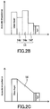
FIG. 2B is another conceptual diagram showing the distribution of acoustic impedance. -
FIG. 2C is yet another conceptual diagram showing the distribution of acoustic impedance. -
FIG. 3 is a graph showing the Weibull distribution of ball-point pen drop test results for Example 1, Example 2, Example 3, Comparative Example 1, and Comparative Example 2. - As a result of a detailed study, the present inventors have found that the conventional cover glasses have the following problems.
- Fracture occurring when a hard object collides with a glass sheet at a high velocity and small contact area is called Hertzian fracture. Hertzian fracture is fracture due to an elastic wave (shock wave) occurring at a collision. In the case of a cover glass (
FIG. 1 of Patent Literature 2) having a laminated structure of a glass layer, OCA layer, and PET film, an elastic wave occurring at a collision is reflected at the interface between the glass layer and OCA layer to produce a standing elastic wave. At that time, a strong tensile stress is applied to a latent scratch on the surface of the glass layer to extend a crack, which causes fracture of the cover glass. According to a dynamic simulation, when a 5-g ball-point pen having a high-hardness steel pen point (diameter: 0.7 mm) is dropped from a height of 23 cm or more and caused to vertically collide with the surface of a cover glass, a 50-kgf or larger load is applied as impact force to the cover glass. When the ball-point pen is dropped from a height of 1 m, a load larger than 100 kgf is applied to the cover glass as impact force. The collision time is about 11 µsec. - Inside the OCA layer, the elastic wave is attenuated due to viscous deformation of the OCA layer. However, if the viscosity coefficient of the resin composing the OCA layer is small, the attenuation of the elastic wave is weak and a standing wave with a free end is formed between the glass layer/OCA layer interface and OCA layer/PET film interface. Consequently, delamination may occur at the interface between the glass layer and OCA layer or the OCA layer itself may fracture.
- Hereinafter, an embodiment of the present invention will be described with reference to the drawings. The present invention is not limited to the following embodiment.
- As shown in
FIG. 1 , acover glass 10 of the present embodiment includes aviscoelastic layer 12, acoustic impedance adjustinglayer 14, andglass layer 16. The acoustic impedance adjustinglayer 14 is disposed between theglass layer 16 andviscoelastic layer 12. That is, theviscoelastic layer 12, acoustic impedance adjustinglayer 14, andglass layer 16 are laminated in this order. In the present embodiment, theviscoelastic layer 12 is in contact with the acoustic impedance adjustinglayer 14. The acoustic impedance adjustinglayer 14 is in contact with theglass layer 16. Theglass layer 16 forms the outermost surface of thecover glass 10. Thecover glass 10 is attached to a screen of a display body so that theviscoelastic layer 12 will be in contact with the display body directly or via another layer. - The
viscoelastic layer 12 is a layer formed of a resin transparent to visible light (commonly a colorless and transparent resin). Theviscoelastic layer 12 is formed of a resin material having adhesiveness, such as an acrylic adhesive. Theviscoelastic layer 12 is typically formed of an optical clear adhesive film (OCA film) or UV curable optical clear resin (OCR). It is not essential for theviscoelastic layer 12 to have adhesiveness. If theviscoelastic layer 12 does not have adhesiveness, an adhesive is additionally needed to attach thecover glass 10 onto a display body. - The acoustic impedance adjusting
layer 14 is a layer for matching acoustic impedance between theviscoelastic layer 12 andglass layer 16. The material of the acousticimpedance adjusting layer 14 is not particularly limited as long as the material can achieve the above function and is transparent to visible light (commonly colorless and transparent). The material composition of the acousticimpedance adjusting layer 14 is different from that of theviscoelastic layer 12. The acousticimpedance adjusting layer 14 is formed of, for example, at least one resin selected from the group consisting of polyethylene (PE), polymethyl methacrylate (PMMA), polycarbonate (PC), polypropylene (PP), polyester, polyimide, and polyamide. The polyethylene may be a high-density polyethylene and may be a low-density polyethylene. Examples of the polyester include polyethylene terephthalate (PET). Examples of the polyamide include nylon 6 and nylon 6,6. The acousticimpedance adjusting layer 14 may be formed of an inorganic material such as SiO2 and BN in some cases. - The
glass layer 16 is formed of, for example, a strengthened glass sheet. Examples of the strengthened glass sheet include a chemically strengthened glass sheet. The chemically strengthened glass sheet can be produced by a chemical strengthening method in which a glass sheet is treated in a melt of an alkali metal salt to impart a compressive stress to the surface layer portion of the glass sheet. The glass sheet used for the production of the chemically strengthened glass sheet is produced by, for example, float process and has composition of a known glass such as soda-lime glass and aluminosilicate glass. - When the acoustic impedance of the
glass layer 16 is Zg, the acoustic impedance of the acousticimpedance adjusting layer 14 is Zm, and the acoustic impedance of theviscoelastic layer 12 is Zd, the cover glass of the present embodiment satisfies a relationship of Zg > Zm > Zd. When the respective acoustic impedance Zg, Zm, and Zd of the layers satisfy this relationship, the following effect can be obtained. That is, the interface reflection of an elastic wave generated upon impact on the surface of thecover glass 10 is suppressed, and thus the generation of a standing wave is also suppressed. Since theglass layer 16 is less likely to be subjected to a strong tensile stress, thecover glass 10 is not easily fractured. This effect is owing also to the fact that theviscoelastic layer 12 absorbs an elastic wave transmitted through the interfaces. When theviscoelastic layer 12 and acousticimpedance adjusting layer 14 are each formed of a resin material, fracture at the interface between theviscoelastic layer 12 and acousticimpedance adjusting layer 14 can be effectively prevented. Theoretically, the best effect can be obtained when the relationship of Zm = (Zg • Zd)1/2 is satisfied. - The acoustic
impedance adjusting layer 14 may be a layer having a single acoustic impedance. The acousticimpedance adjusting layer 14 may also be a layer formed by laminating a plurality of layers each having a different acoustic impedance. As shown inFIG. 2A , a plurality oflayers 14a to 14c forming the acousticimpedance adjusting layer 14 are laminated, for example, so as to gradually decrease the acoustic impedance from theglass layer 16 to theviscoelastic layer 12. - Additionally, a layer whose acoustic impedance is larger than the acoustic impedance of the
glass layer 16 may be disposed between the acousticimpedance adjusting layer 14 andglass layer 16 as long as the relationship of Zg > Zm > Zd is satisfied. Moreover, as shown inFIG. 2B , when the acousticimpedance adjusting layer 14 is composed of a plurality of layers 14d to 14f, the layer 14e whose acoustic impedance is larger than the acoustic impedance of theglass layer 16 may be included in the plurality of layers 14d to 14f. In other words, the acousticimpedance adjusting layer 14 may have a laminated structure composed of at least one layer (the layers 14d and 14f) satisfying the relationship of Zg > Zm > Zd and a layer (the layer 14e) whose acoustic impedance is larger than the acoustic impedance of theglass layer 16. Furthermore, a plurality of layers composing the acousticimpedance adjusting layer 14 may include a layer whose acoustic impedance is smaller than the acoustic impedance Zd of theviscoelastic layer 12. - As shown in
FIG. 2C , in the acousticimpedance adjusting layer 14, the acoustic impedance may continuously decrease from theglass layer 16 to theviscoelastic layer 12. In the acousticimpedance adjusting layer 14, the acoustic impedance may decrease lineally or non-lineally. - As represented by the following equation, the acoustic impedance Z (kg/m2 • sec) is defined by the product of the density ρ (kg/m3) of a medium and sonic velocity c (m/sec) in the medium. In other words, the acoustic impedance Z is defined by the square root of the product of the density ρ of the medium and Young's modulus E of the medium. The medium is at ordinary temperature (20°C ± 15°C: Japanese Industrial Standards (JIS) Z 8703). The sonic velocity c in the medium can be measured with a sing-around sonic velocity measuring apparatus.


- The thickness of the
cover glass 10 is, for example, within the range of 0.015 to 0.15 mm. - The thickness td of the
viscoelastic layer 12 is, for example, less than 0.1 mm. By sufficiently reducing the thickness of theviscoelastic layer 12, deformation of theglass layer 16 caused upon impact to theglass layer 16 can be reduced. The lower limit of the thickness td of theviscoelastic layer 12 is not particularly limited. The lower limit of the thickness td is, for example, 10 µm. - The thickness tm of the acoustic
impedance adjusting layer 14 is, for example, within the range of 0.003 to 20 µm. - The thickness tg of the
glass layer 16 is, for example, within the range of 0.015 to 0.15 mm. Reduction in the thickness of theglass layer 16 decreases the bending rigidity of thecover glass 10. As a result, thecover glass 10 resistant to damage from sharp bending (for example, to a curvature radius of 5 mm) can be provided. That is, thecover glass 10 can be made more suitable for a flexible display. - In the
cover glass 10 of the present embodiment, the thickness tg of theglass layer 16, the thickness tm of the acousticimpedance adjusting layer 14, and the thickness td of theviscoelastic layer 12 satisfy a relationship of (tm + td) ≥ 0.0002 tg. The thicknesses tg, tm, and td desirably satisfy a relationship of (tm + td) ≥ 0.2 tg. When the layers satisfy the relationship, the effect of suppressing the elastic wave reflection at the interfaces between the layers can be obtained sufficiently. The upper limit of the sum of the thicknesses tm and td is not particularly limited. The thicknesses tg, tm, and td satisfy, for example, a relationship of 2 • tg ≥ (tm + td). - In the present embodiment, the viscosity of the
viscoelastic layer 12 is within the range of 0.0001 to 20000 Pa • sec at ordinary temperature. When the viscosity of theviscoelastic layer 12 is within this range, the standing elastic wave can be effectively attenuated. The elastic modulus (tensile elastic modulus (Young's modulus)) of theviscoelastic layer 12 is, for example, within the range of 30E+3 to 5E+9 (Pa). - The viscosity and elastic modulus of the
viscoelastic layer 12 respectively represent the viscosity and elastic modulus of the material forming theviscoelastic layer 12. The viscosity can be measured by, for example, an ultrasonic viscometer. The measurement principle of the ultrasonic viscometer is as follows. When an oscillator is put in a specimen and oscillated, the amplitude varies according to friction between the specimen and oscillator. An electric current is then applied externally to keep the amplitude of the oscillator constant. The viscosity can be determined from the value of the electric current applied at this time. The elastic modulus can be measured by, for example, a dynamic viscoelasticity measuring apparatus (rheometer). The measurement principle of the dynamic viscoelasticity measuring apparatus can be roughly described as follows. A stress is cyclically applied to a specimen to allow measurement of a viscoelastic modulus of the specimen from waveforms of shearing stress and a phase difference therebetween. A test piece having the same material composition as theviscoelastic layer 12 can be prepared for use in the measurement of the viscosity and elastic modulus. - A PMMA solution was applied to the back surface of a 48-µm-thick chemically strengthened glass sheet (glanova (registered trademark) manufactured by Nippon Sheet Glass Co., Ltd.) by slit and spin coating to form a coating film, which was then dried to form a 1.3-µm-thick acoustic impedance adjusting layer. Next, a 20-µm-thick OCA film (manufactured by 3M) made of an acrylic adhesive was bonded onto the acoustic impedance adjusting layer. A cover glass of Example 1 was thus obtained.
- A 1.3-µm-thick PET film was bonded as an acoustic impedance adjusting layer to the back surface of a 48-µm-thick chemically strengthened glass sheet (glanova (registered trademark) manufactured by Nippon Sheet Glass Co., Ltd.). A transparent acrylic adhesive was used in the bonding of the PET film and glass sheet. Next, a 20-µm-thick OCA film (manufactured by 3M) made of an acrylic adhesive was bonded onto the acoustic impedance adjusting layer. A cover glass of Example 2 was thus obtained.
- A 2.2-µm-thick PET film was bonded as an acoustic impedance adjusting layer to the back surface of a 48-µm-thick chemically strengthened glass sheet (glanova (registered trademark) manufactured by Nippon Sheet Glass Co., Ltd.). A transparent acrylic adhesive was used in the bonding of the PET film and glass sheet. Next, a 20-µm-thick OCA film (manufactured by 3M) made of an acrylic adhesive was bonded onto the acoustic impedance adjusting layer. A cover glass of Example 3 was thus obtained.
- A 20-µm-thick OCA film (manufactured by 3M) made of an acrylic adhesive was bonded to the back surface of a 48-µm-thick chemically strengthened glass sheet (glanova (registered trademark) manufactured by Nippon Sheet Glass Co., Ltd.). A cover glass of Comparative Example 1 was thus obtained.
- A 25-nm-thick Si3N4 film was formed on the back surface of a 48-µm-thick chemically strengthened glass sheet (glanova (registered trademark) manufactured by Nippon Sheet Glass Co., Ltd.) by a sputtering method. Next, a 20-µm-thick OCA film (manufactured by 3M) made of an acrylic adhesive was bonded onto the Si3N4 film. A cover glass of Comparative Example 2 was thus obtained.
- First, the cover glass of each of Examples and Comparative Examples was bonded to a PET film (thickness: 30 µm) serving as a simulated flexible display. A laminated product of the cover glass and PET film was thus obtained. Next, the laminated product was disposed on a 5-mm-thick glass sheet with the cover glass side up. A specimen for the ball-point pen drop test was thus obtained. A 5-g ball-point pen having a high-hardness steel pen point (diameter: 0.7 mm) was dropped on the surface of the cover glass to determine the height at fracture of the cover glass. Specifically, the ball-point pen was dropped toward a certain point on the cover glass, and the height at fracture of the cover glass was recorded. The dropping of the ball-point pen started from a height of 1 cm, and the drop height was increased by 1 cm. From the cover glass of each of Example 1, Example 2, Comparative Example 1, and Comparative Example 2 were prepared 22 specimens, which were subjected to the ball-point pen drop test. From the cover glass of Example 3 were prepared 11 specimens, which were subjected to the ball-point pen drop test. The test results are shown in Table 1 and
FIG. 3. FIG. 3 shows the Weibull distribution of the test results. The column headed "B10 (/cm)" in Table 1 shows the height at fracture of 10% of the specimens. - The intensity transmittance of a shock wave propagating from the glass layer to the OCA layer in the cover glass of each of Examples and Comparative Examples was theoretically calculated using the acoustic impedance of each layer. The results are shown in Table 1.
[Table 1] Structure Intensity transmittance of shock wave (%) B10 (/cm) (Weibull distribution data) Average fracture height (cm) (Weibull distribution data) Example 1 Glass/PMMA/OCA 13 23.6 32.8 Example 2 Glass/PET/ OCA 12 23.3 28.1 Example 3 Glass/PET/ OCA 12 27.2 36.7 Comparative Example 1 Glass/OCA 5 8.6 16.5 Comparative Example 2 Glass/Si3N4/ OCA 2 0.6 1.1 - The average fracture height in Examples 1 to 3 greatly exceeded the average fracture height in Comparative Examples 1 and 2. The average fracture height in Example 3 was the greatest. It can be thought that the elastic wave reflection at the interfaces was suppressed by the impedance matching between the glass layer and viscoelastic layer and thus the stress applied to a crack on the surface of the glass layer was decreased, which resulted in the increase in the average fracture height. In Example 1, the acoustic impedance Zg of the glass layer (glanova (registered trademark)) was 1.4E+07 (kg/m2 • s), the acoustic impedance Zm of the acoustic impedance adjusting layer (PMMA) was 1.7E+06 (kg/m2 • s), and the acoustic impedance Zd of the viscoelastic layer (OCA) was 1.8E+05 (kg/m2 • s); thus, the relationship of Zg > Zm > Zd was satisfied. Also in Examples 2 and 3, the acoustic impedance Zm of the acoustic impedance adjusting layer (PET) was 3.0 E+06 (kg/m2 • s), and the relationship of Zg > Zm > Zd was satisfied.
- As can be understood from the Weibull distribution in
FIG. 3 , values of the ball-point pen fracture height in Comparative Examples 1 and 2 were lower on the whole than values of the ball-point pen fracture height in Examples 1 to 3. In particular, Comparative Example 2 was inferior even to Comparative Example 1. For Comparative Example 2, it can be thought that, because of high reflection of the elastic wave at the interface between the glass layer and Si3N4 film and substantial coincidence between the position of the antinode of the standing wave and the position of the interface, the maximum stress became twice larger and even a small impact caused fracture. In Comparative Example 2, the acoustic impedance (= 3.1E+07 (kg/m2 • s)) of the Si3N4 film provided between the glass layer and viscoelastic layer was larger than the acoustic impedance (= 1.4E+07 (kg/m2 • s)) of the glass layer. - The cover glasses in which the intensity transmittance of the shock wave propagating from the glass layer to the viscoelastic layer was 10% or higher were excellent in the impact resistance. The upper limit of the intensity transmittance is, for example, 12%, and desirably 13%. When the intensity transmittance is at or above a certain level, performance of the viscoelastic layer in absorbing the shock wave is more likely to be exerted. Therefore, the upper limit of the intensity transmittance is not particularly limited.
- The technique disclosed herein is useful for cover glasses used to protect displays. The displays are not limited to those of a particular type, and examples thereof include displays of mobile devices, TV sets, and navigation systems.
Claims (6)
- A cover glass comprising:a glass layer;a viscoelastic layer; andan acoustic impedance adjusting layer disposed between the glass layer and the viscoelastic layer, whereinwhen acoustic impedance of the glass layer is Zg, acoustic impedance of the acoustic impedance adjusting layer is Zm, and acoustic impedance of the viscoelastic layer is Zd, a relationship of Zg > Zm > Zd is satisfied.
- The cover glass according to claim 1, wherein the viscoelastic layer and the acoustic impedance adjusting layer are each made of a material transparent to visible light.
- The cover glass according to claim 1 or 2, wherein the viscoelastic layer is composed of an optical clear adhesive film.
- The cover glass according to any one of claims 1 to 3, wherein the impedance adjusting layer is made of at least one resin selected from the group consisting of polyethylene, polymethyl methacrylate, polycarbonate, polypropylene, polyester, polyimide, and polyamide.
- The cover glass according to any one of claims 1 to 4, wherein intensity transmittance of a shock wave propagating from the glass layer to the viscoelastic layer is 10% or higher.
- A display comprising:a display body; andthe cover glass according to any one of claims 1 to 5, the cover glass being attached to a screen of the display body.
Applications Claiming Priority (2)
| Application Number | Priority Date | Filing Date | Title |
|---|---|---|---|
| JP2016185182 | 2016-09-23 | ||
| PCT/JP2017/031021 WO2018055998A1 (en) | 2016-09-23 | 2017-08-29 | Cover glass and display using same |
Publications (3)
| Publication Number | Publication Date |
|---|---|
| EP3517512A1 true EP3517512A1 (en) | 2019-07-31 |
| EP3517512A4 EP3517512A4 (en) | 2020-06-03 |
| EP3517512B1 EP3517512B1 (en) | 2024-11-13 |
Family
ID=61689495
Family Applications (1)
| Application Number | Title | Priority Date | Filing Date |
|---|---|---|---|
| EP17852777.6A Active EP3517512B1 (en) | 2016-09-23 | 2017-08-29 | Cover glass and display using same |
Country Status (7)
| Country | Link |
|---|---|
| US (1) | US11155492B2 (en) |
| EP (1) | EP3517512B1 (en) |
| JP (1) | JP7015240B2 (en) |
| KR (1) | KR102494878B1 (en) |
| CN (1) | CN109415248B (en) |
| TW (1) | TWI730164B (en) |
| WO (1) | WO2018055998A1 (en) |
Families Citing this family (12)
| Publication number | Priority date | Publication date | Assignee | Title |
|---|---|---|---|---|
| JP6817257B2 (en) * | 2018-07-31 | 2021-01-20 | 株式会社Joled | Protective sheets, display devices and electronic devices |
| EP3840947A1 (en) * | 2018-08-24 | 2021-06-30 | Corning Incorporated | Article comprising puncture resistant laminate with ultra-thin glass layer |
| KR102671730B1 (en) * | 2018-09-21 | 2024-06-04 | 삼성전자주식회사 | Protection film and electronic device therewith |
| KR102304521B1 (en) * | 2019-09-26 | 2021-09-24 | 리얼룩앤컴퍼니 주식회사 | Ultrasonic fingerprint recognition display protective film |
| CN121398359A (en) | 2020-03-23 | 2026-01-23 | 大日本印刷株式会社 | Flexible organic EL display device and front panel for display device |
| US11656698B1 (en) * | 2020-05-28 | 2023-05-23 | Nissha Co., Ltd. | Touch sensor and input device |
| KR102774715B1 (en) | 2020-06-03 | 2025-03-05 | 삼성디스플레이 주식회사 | Window and display device including the same |
| JP7471956B2 (en) * | 2020-08-21 | 2024-04-22 | 太陽ホールディングス株式会社 | Laminate |
| JP7547892B2 (en) * | 2020-09-18 | 2024-09-10 | 大日本印刷株式会社 | Display device components, display devices and electronic devices |
| KR102549675B1 (en) * | 2021-08-05 | 2023-06-30 | (주)유티아이 | Flexible Cover Window with Improved Strength |
| JP2023117335A (en) * | 2022-02-10 | 2023-08-23 | 日東電工株式会社 | Substrate for window, multi-layer window, multi-layer window with adhesive layer, and display device including multi-layer window |
| JP2023117334A (en) * | 2022-02-10 | 2023-08-23 | 日東電工株式会社 | Substrate for window, multi-layer window, multi-layer window with adhesive layer, and display device including multi-layer window |
Family Cites Families (23)
| Publication number | Priority date | Publication date | Assignee | Title |
|---|---|---|---|---|
| JPH0450144A (en) * | 1990-06-18 | 1992-02-19 | Asahi Fiber Glass Co Ltd | Rubber-reinforcing fiber |
| JP3726100B2 (en) * | 1994-09-12 | 2005-12-14 | 株式会社翠光トップライン | Thermal insulation glass |
| US7241485B2 (en) * | 2001-11-09 | 2007-07-10 | Toray Industries, Inc. | Protective film for glass |
| EP1339082A1 (en) | 2002-02-25 | 2003-08-27 | Asahi Glass Company Ltd. | Impact-resistant film for flat display panel, and flat display panel |
| JP4575486B2 (en) | 2007-10-24 | 2010-11-04 | セイコーインスツル株式会社 | Display device |
| US20090263651A1 (en) * | 2008-02-06 | 2009-10-22 | Cook Richard L | Optically transparent resilient laminate materials and methods of manufacture |
| JPWO2011096467A1 (en) | 2010-02-04 | 2013-06-10 | 日本板硝子株式会社 | Glass with resin parts |
| CN104684861B (en) * | 2012-06-08 | 2018-02-23 | 康宁股份有限公司 | Laminated glass construction with high glass, polymer intermediate layer adhesion strength |
| TWI441729B (en) * | 2012-12-17 | 2014-06-21 | 王靖夫 | Protective film |
| KR101336934B1 (en) | 2013-03-05 | 2013-12-03 | 크루셜텍 (주) | Cover glass and method of manufacturing the same |
| TWI631019B (en) * | 2013-04-19 | 2018-08-01 | 美商康寧公司 | Methods of forming laminated glass structures |
| US20150086048A1 (en) * | 2013-09-20 | 2015-03-26 | Corning Incorporated | Acoustic panels and planar structures |
| JP2015225365A (en) * | 2014-05-26 | 2015-12-14 | 凸版印刷株式会社 | Cover glass integrated touch panel sensor substrate and manufacturing method thereof |
| JP3196581U (en) * | 2014-06-04 | 2015-03-26 | 株式会社サンクレスト | Shock absorbing tempered glass cover |
| DE112015004049T5 (en) * | 2014-09-05 | 2017-06-14 | Asahi Glass Company, Limited | An adhesive layer provided with transparent plate and adhesive layer |
| TWM504700U (en) * | 2014-10-20 | 2015-07-11 | G Tech Optoelectronics Corp | Non-planar tempered glass protector for portable electronic devices |
| JP6344207B2 (en) * | 2014-11-11 | 2018-06-20 | 大日本印刷株式会社 | Manufacturing method of cover glass |
| KR102318107B1 (en) * | 2014-12-24 | 2021-10-28 | 린텍 가부시키가이샤 | Double-sided adhesive sheet for surface protective panels, and surface protective panel |
| CN104656993A (en) * | 2015-02-13 | 2015-05-27 | 业成光电(深圳)有限公司 | Film type touch panel structure |
| CN105204680A (en) * | 2015-07-13 | 2015-12-30 | 维沃移动通信有限公司 | Screen, screen manufacturing method and mobile electronic product |
| CN105446530A (en) * | 2015-11-19 | 2016-03-30 | 业成光电(深圳)有限公司 | Display module structure of mobile electronic device |
| US20180082669A1 (en) * | 2016-09-20 | 2018-03-22 | Solutia Inc. | Sound attenuating multiple layer laminates |
| WO2018057774A1 (en) | 2016-09-21 | 2018-03-29 | 3M Innovative Properties Company | Protective display film with glass |
-
2017
- 2017-08-29 KR KR1020197001671A patent/KR102494878B1/en active Active
- 2017-08-29 WO PCT/JP2017/031021 patent/WO2018055998A1/en not_active Ceased
- 2017-08-29 US US16/307,384 patent/US11155492B2/en active Active
- 2017-08-29 CN CN201780041965.7A patent/CN109415248B/en active Active
- 2017-08-29 JP JP2018540936A patent/JP7015240B2/en active Active
- 2017-08-29 EP EP17852777.6A patent/EP3517512B1/en active Active
- 2017-09-01 TW TW106129879A patent/TWI730164B/en active
Also Published As
| Publication number | Publication date |
|---|---|
| JPWO2018055998A1 (en) | 2019-07-04 |
| KR20190058447A (en) | 2019-05-29 |
| TW201826237A (en) | 2018-07-16 |
| WO2018055998A1 (en) | 2018-03-29 |
| TWI730164B (en) | 2021-06-11 |
| EP3517512B1 (en) | 2024-11-13 |
| EP3517512A4 (en) | 2020-06-03 |
| JP7015240B2 (en) | 2022-02-02 |
| US11155492B2 (en) | 2021-10-26 |
| US20190300425A1 (en) | 2019-10-03 |
| KR102494878B1 (en) | 2023-02-02 |
| CN109415248B (en) | 2021-09-03 |
| CN109415248A (en) | 2019-03-01 |
Similar Documents
| Publication | Publication Date | Title |
|---|---|---|
| EP3517512B1 (en) | Cover glass and display using same | |
| CN111696439B (en) | Flexible covering window | |
| EP3299162B1 (en) | Window for display device and display device | |
| US10906837B2 (en) | Strengthened glass articles exhibiting improved headform impact performance and automotive interior systems incorporating the same | |
| EP3215472B1 (en) | Bendable glass articles with alkali-free glass elements | |
| EP4029691A1 (en) | Bendable glass stack assemblies and methods of making the same | |
| EP3695445A1 (en) | Foldable electronic device modules with impact and bend resistance | |
| KR20180104002A (en) | A seal having an improved tactile surface | |
| JP2020523633A (en) | Bendable laminated article including anisotropic layer | |
| KR102885188B1 (en) | Flexible organic EL display devices and front panels for display devices | |
| TW201923427A (en) | Display module with quasi-static and dynamic impact resistance | |
| CN111201131A (en) | Impact-resistant pre-broken glass composites and laminates and methods of making the same | |
| CN110497665A (en) | Laminated body and display device | |
| US20220298064A1 (en) | Foldable cover article with reduced hazardous projects | |
| WO2020018312A1 (en) | Redrawn glass having enhanced puncture resistance | |
| JP7782191B2 (en) | Glass substrate, glass laminate, display device and electronic device | |
| CN110824747B (en) | display device | |
| WO2023153052A1 (en) | Window base material, multilayer window, multilayer window with adhesive layer, and display device including multilayer window | |
| WO2024005128A1 (en) | Layered body, display device, and member for layered body | |
| KR20130101287A (en) | The transparent multi layer film for the portable device | |
| WO2023211731A1 (en) | Impact-resistant glass-polymer laminates and sensors incorporating the same | |
| KR20130101717A (en) | The transparent multi layer film for the protection | |
| WO2023153051A1 (en) | Window base material, multilayer window, multilayer window with adhesive layer, and display device including multilayer window | |
| KR20130101286A (en) | The transparent multi layer film for the protection |
Legal Events
| Date | Code | Title | Description |
|---|---|---|---|
| STAA | Information on the status of an ep patent application or granted ep patent |
Free format text: STATUS: THE INTERNATIONAL PUBLICATION HAS BEEN MADE |
|
| PUAI | Public reference made under article 153(3) epc to a published international application that has entered the european phase |
Free format text: ORIGINAL CODE: 0009012 |
|
| STAA | Information on the status of an ep patent application or granted ep patent |
Free format text: STATUS: REQUEST FOR EXAMINATION WAS MADE |
|
| 17P | Request for examination filed |
Effective date: 20190418 |
|
| AK | Designated contracting states |
Kind code of ref document: A1 Designated state(s): AL AT BE BG CH CY CZ DE DK EE ES FI FR GB GR HR HU IE IS IT LI LT LU LV MC MK MT NL NO PL PT RO RS SE SI SK SM TR |
|
| AX | Request for extension of the european patent |
Extension state: BA ME |
|
| DAV | Request for validation of the european patent (deleted) | ||
| DAX | Request for extension of the european patent (deleted) | ||
| A4 | Supplementary search report drawn up and despatched |
Effective date: 20200504 |
|
| RIC1 | Information provided on ipc code assigned before grant |
Ipc: G09F 9/00 20060101ALI20200424BHEP Ipc: B32B 17/10 20060101ALI20200424BHEP Ipc: C03C 17/32 20060101AFI20200424BHEP |
|
| STAA | Information on the status of an ep patent application or granted ep patent |
Free format text: STATUS: EXAMINATION IS IN PROGRESS |
|
| 17Q | First examination report despatched |
Effective date: 20211102 |
|
| GRAP | Despatch of communication of intention to grant a patent |
Free format text: ORIGINAL CODE: EPIDOSNIGR1 |
|
| STAA | Information on the status of an ep patent application or granted ep patent |
Free format text: STATUS: GRANT OF PATENT IS INTENDED |
|
| INTG | Intention to grant announced |
Effective date: 20240213 |
|
| GRAJ | Information related to disapproval of communication of intention to grant by the applicant or resumption of examination proceedings by the epo deleted |
Free format text: ORIGINAL CODE: EPIDOSDIGR1 |
|
| STAA | Information on the status of an ep patent application or granted ep patent |
Free format text: STATUS: EXAMINATION IS IN PROGRESS |
|
| INTC | Intention to grant announced (deleted) | ||
| GRAP | Despatch of communication of intention to grant a patent |
Free format text: ORIGINAL CODE: EPIDOSNIGR1 |
|
| STAA | Information on the status of an ep patent application or granted ep patent |
Free format text: STATUS: GRANT OF PATENT IS INTENDED |
|
| GRAS | Grant fee paid |
Free format text: ORIGINAL CODE: EPIDOSNIGR3 |
|
| INTG | Intention to grant announced |
Effective date: 20240906 |
|
| GRAA | (expected) grant |
Free format text: ORIGINAL CODE: 0009210 |
|
| STAA | Information on the status of an ep patent application or granted ep patent |
Free format text: STATUS: THE PATENT HAS BEEN GRANTED |
|
| AK | Designated contracting states |
Kind code of ref document: B1 Designated state(s): AL AT BE BG CH CY CZ DE DK EE ES FI FR GB GR HR HU IE IS IT LI LT LU LV MC MK MT NL NO PL PT RO RS SE SI SK SM TR |
|
| REG | Reference to a national code |
Ref country code: GB Ref legal event code: FG4D |
|
| REG | Reference to a national code |
Ref country code: CH Ref legal event code: EP |
|
| P01 | Opt-out of the competence of the unified patent court (upc) registered |
Free format text: CASE NUMBER: APP_55573/2024 Effective date: 20241010 |
|
| REG | Reference to a national code |
Ref country code: DE Ref legal event code: R096 Ref document number: 602017086144 Country of ref document: DE |
|
| REG | Reference to a national code |
Ref country code: IE Ref legal event code: FG4D |
|
| REG | Reference to a national code |
Ref country code: LT Ref legal event code: MG9D |
|
| REG | Reference to a national code |
Ref country code: NL Ref legal event code: MP Effective date: 20241113 |
|
| PG25 | Lapsed in a contracting state [announced via postgrant information from national office to epo] |
Ref country code: IS Free format text: LAPSE BECAUSE OF FAILURE TO SUBMIT A TRANSLATION OF THE DESCRIPTION OR TO PAY THE FEE WITHIN THE PRESCRIBED TIME-LIMIT Effective date: 20250313 Ref country code: HR Free format text: LAPSE BECAUSE OF FAILURE TO SUBMIT A TRANSLATION OF THE DESCRIPTION OR TO PAY THE FEE WITHIN THE PRESCRIBED TIME-LIMIT Effective date: 20241113 Ref country code: PT Free format text: LAPSE BECAUSE OF FAILURE TO SUBMIT A TRANSLATION OF THE DESCRIPTION OR TO PAY THE FEE WITHIN THE PRESCRIBED TIME-LIMIT Effective date: 20250313 |
|
| PG25 | Lapsed in a contracting state [announced via postgrant information from national office to epo] |
Ref country code: FI Free format text: LAPSE BECAUSE OF FAILURE TO SUBMIT A TRANSLATION OF THE DESCRIPTION OR TO PAY THE FEE WITHIN THE PRESCRIBED TIME-LIMIT Effective date: 20241113 Ref country code: NL Free format text: LAPSE BECAUSE OF FAILURE TO SUBMIT A TRANSLATION OF THE DESCRIPTION OR TO PAY THE FEE WITHIN THE PRESCRIBED TIME-LIMIT Effective date: 20241113 |
|
| REG | Reference to a national code |
Ref country code: AT Ref legal event code: MK05 Ref document number: 1741602 Country of ref document: AT Kind code of ref document: T Effective date: 20241113 |
|
| PG25 | Lapsed in a contracting state [announced via postgrant information from national office to epo] |
Ref country code: BG Free format text: LAPSE BECAUSE OF FAILURE TO SUBMIT A TRANSLATION OF THE DESCRIPTION OR TO PAY THE FEE WITHIN THE PRESCRIBED TIME-LIMIT Effective date: 20241113 |
|
| PG25 | Lapsed in a contracting state [announced via postgrant information from national office to epo] |
Ref country code: ES Free format text: LAPSE BECAUSE OF FAILURE TO SUBMIT A TRANSLATION OF THE DESCRIPTION OR TO PAY THE FEE WITHIN THE PRESCRIBED TIME-LIMIT Effective date: 20241113 |
|
| PG25 | Lapsed in a contracting state [announced via postgrant information from national office to epo] |
Ref country code: NO Free format text: LAPSE BECAUSE OF FAILURE TO SUBMIT A TRANSLATION OF THE DESCRIPTION OR TO PAY THE FEE WITHIN THE PRESCRIBED TIME-LIMIT Effective date: 20250213 |
|
| PG25 | Lapsed in a contracting state [announced via postgrant information from national office to epo] |
Ref country code: AT Free format text: LAPSE BECAUSE OF FAILURE TO SUBMIT A TRANSLATION OF THE DESCRIPTION OR TO PAY THE FEE WITHIN THE PRESCRIBED TIME-LIMIT Effective date: 20241113 Ref country code: LV Free format text: LAPSE BECAUSE OF FAILURE TO SUBMIT A TRANSLATION OF THE DESCRIPTION OR TO PAY THE FEE WITHIN THE PRESCRIBED TIME-LIMIT Effective date: 20241113 Ref country code: GR Free format text: LAPSE BECAUSE OF FAILURE TO SUBMIT A TRANSLATION OF THE DESCRIPTION OR TO PAY THE FEE WITHIN THE PRESCRIBED TIME-LIMIT Effective date: 20250214 |
|
| PG25 | Lapsed in a contracting state [announced via postgrant information from national office to epo] |
Ref country code: PL Free format text: LAPSE BECAUSE OF FAILURE TO SUBMIT A TRANSLATION OF THE DESCRIPTION OR TO PAY THE FEE WITHIN THE PRESCRIBED TIME-LIMIT Effective date: 20241113 |
|
| PG25 | Lapsed in a contracting state [announced via postgrant information from national office to epo] |
Ref country code: RS Free format text: LAPSE BECAUSE OF FAILURE TO SUBMIT A TRANSLATION OF THE DESCRIPTION OR TO PAY THE FEE WITHIN THE PRESCRIBED TIME-LIMIT Effective date: 20250213 |
|
| PG25 | Lapsed in a contracting state [announced via postgrant information from national office to epo] |
Ref country code: SM Free format text: LAPSE BECAUSE OF FAILURE TO SUBMIT A TRANSLATION OF THE DESCRIPTION OR TO PAY THE FEE WITHIN THE PRESCRIBED TIME-LIMIT Effective date: 20241113 |
|
| PG25 | Lapsed in a contracting state [announced via postgrant information from national office to epo] |
Ref country code: DK Free format text: LAPSE BECAUSE OF FAILURE TO SUBMIT A TRANSLATION OF THE DESCRIPTION OR TO PAY THE FEE WITHIN THE PRESCRIBED TIME-LIMIT Effective date: 20241113 |
|
| PG25 | Lapsed in a contracting state [announced via postgrant information from national office to epo] |
Ref country code: EE Free format text: LAPSE BECAUSE OF FAILURE TO SUBMIT A TRANSLATION OF THE DESCRIPTION OR TO PAY THE FEE WITHIN THE PRESCRIBED TIME-LIMIT Effective date: 20241113 |
|
| PG25 | Lapsed in a contracting state [announced via postgrant information from national office to epo] |
Ref country code: RO Free format text: LAPSE BECAUSE OF FAILURE TO SUBMIT A TRANSLATION OF THE DESCRIPTION OR TO PAY THE FEE WITHIN THE PRESCRIBED TIME-LIMIT Effective date: 20241113 |
|
| PG25 | Lapsed in a contracting state [announced via postgrant information from national office to epo] |
Ref country code: SK Free format text: LAPSE BECAUSE OF FAILURE TO SUBMIT A TRANSLATION OF THE DESCRIPTION OR TO PAY THE FEE WITHIN THE PRESCRIBED TIME-LIMIT Effective date: 20241113 |
|
| PG25 | Lapsed in a contracting state [announced via postgrant information from national office to epo] |
Ref country code: CZ Free format text: LAPSE BECAUSE OF FAILURE TO SUBMIT A TRANSLATION OF THE DESCRIPTION OR TO PAY THE FEE WITHIN THE PRESCRIBED TIME-LIMIT Effective date: 20241113 |
|
| PG25 | Lapsed in a contracting state [announced via postgrant information from national office to epo] |
Ref country code: IT Free format text: LAPSE BECAUSE OF FAILURE TO SUBMIT A TRANSLATION OF THE DESCRIPTION OR TO PAY THE FEE WITHIN THE PRESCRIBED TIME-LIMIT Effective date: 20241113 |
|
| REG | Reference to a national code |
Ref country code: DE Ref legal event code: R097 Ref document number: 602017086144 Country of ref document: DE |
|
| PG25 | Lapsed in a contracting state [announced via postgrant information from national office to epo] |
Ref country code: SE Free format text: LAPSE BECAUSE OF FAILURE TO SUBMIT A TRANSLATION OF THE DESCRIPTION OR TO PAY THE FEE WITHIN THE PRESCRIBED TIME-LIMIT Effective date: 20241113 |
|
| PLBE | No opposition filed within time limit |
Free format text: ORIGINAL CODE: 0009261 |
|
| STAA | Information on the status of an ep patent application or granted ep patent |
Free format text: STATUS: NO OPPOSITION FILED WITHIN TIME LIMIT |
|
| PGFP | Annual fee paid to national office [announced via postgrant information from national office to epo] |
Ref country code: DE Payment date: 20250702 Year of fee payment: 9 |
|
| PGFP | Annual fee paid to national office [announced via postgrant information from national office to epo] |
Ref country code: GB Payment date: 20250703 Year of fee payment: 9 |
|
| PGFP | Annual fee paid to national office [announced via postgrant information from national office to epo] |
Ref country code: FR Payment date: 20250703 Year of fee payment: 9 |
|
| 26N | No opposition filed |
Effective date: 20250814 |
|
| REG | Reference to a national code |
Ref country code: CH Ref legal event code: H13 Free format text: ST27 STATUS EVENT CODE: U-0-0-H10-H13 (AS PROVIDED BY THE NATIONAL OFFICE) Effective date: 20260324 |
|
| PG25 | Lapsed in a contracting state [announced via postgrant information from national office to epo] |
Ref country code: MC Free format text: LAPSE BECAUSE OF FAILURE TO SUBMIT A TRANSLATION OF THE DESCRIPTION OR TO PAY THE FEE WITHIN THE PRESCRIBED TIME-LIMIT Effective date: 20241113 |
|
| PG25 | Lapsed in a contracting state [announced via postgrant information from national office to epo] |
Ref country code: LU Free format text: LAPSE BECAUSE OF NON-PAYMENT OF DUE FEES Effective date: 20250829 |
|
| PG25 | Lapsed in a contracting state [announced via postgrant information from national office to epo] |
Ref country code: CH Free format text: LAPSE BECAUSE OF NON-PAYMENT OF DUE FEES Effective date: 20250831 |