EP3517495A1 - Hydrogen storage body, gaschromic dimming element, hydrogen sensing element, and hydrogen sensor - Google Patents
Hydrogen storage body, gaschromic dimming element, hydrogen sensing element, and hydrogen sensor Download PDFInfo
- Publication number
- EP3517495A1 EP3517495A1 EP17852727.1A EP17852727A EP3517495A1 EP 3517495 A1 EP3517495 A1 EP 3517495A1 EP 17852727 A EP17852727 A EP 17852727A EP 3517495 A1 EP3517495 A1 EP 3517495A1
- Authority
- EP
- European Patent Office
- Prior art keywords
- hydrogen
- hydrogen occlusion
- layer
- catalyst layer
- occlusion body
- Prior art date
- Legal status (The legal status is an assumption and is not a legal conclusion. Google has not performed a legal analysis and makes no representation as to the accuracy of the status listed.)
- Granted
Links
Images




Classifications
-
- G—PHYSICS
- G02—OPTICS
- G02F—OPTICAL DEVICES OR ARRANGEMENTS FOR THE CONTROL OF LIGHT BY MODIFICATION OF THE OPTICAL PROPERTIES OF THE MEDIA OF THE ELEMENTS INVOLVED THEREIN; NON-LINEAR OPTICS; FREQUENCY-CHANGING OF LIGHT; OPTICAL LOGIC ELEMENTS; OPTICAL ANALOGUE/DIGITAL CONVERTERS
- G02F1/00—Devices or arrangements for the control of the intensity, colour, phase, polarisation or direction of light arriving from an independent light source, e.g. switching, gating or modulating; Non-linear optics
- G02F1/01—Devices or arrangements for the control of the intensity, colour, phase, polarisation or direction of light arriving from an independent light source, e.g. switching, gating or modulating; Non-linear optics for the control of the intensity, phase, polarisation or colour
- G02F1/19—Devices or arrangements for the control of the intensity, colour, phase, polarisation or direction of light arriving from an independent light source, e.g. switching, gating or modulating; Non-linear optics for the control of the intensity, phase, polarisation or colour based on variable-reflection or variable-refraction elements not provided for in groups G02F1/015 - G02F1/169
-
- C—CHEMISTRY; METALLURGY
- C01—INORGANIC CHEMISTRY
- C01B—NON-METALLIC ELEMENTS; COMPOUNDS THEREOF; METALLOIDS OR COMPOUNDS THEREOF NOT COVERED BY SUBCLASS C01C
- C01B3/00—Hydrogen; Gaseous mixtures containing hydrogen; Separation of hydrogen from mixtures containing it; Purification of hydrogen; Reversible storage of hydrogen
- C01B3/0005—Reversible storage of hydrogen, e.g. by hydrogen getters or electrodes
-
- B—PERFORMING OPERATIONS; TRANSPORTING
- B01—PHYSICAL OR CHEMICAL PROCESSES OR APPARATUS IN GENERAL
- B01J—CHEMICAL OR PHYSICAL PROCESSES, e.g. CATALYSIS OR COLLOID CHEMISTRY; THEIR RELEVANT APPARATUS
- B01J23/00—Catalysts comprising metals or metal oxides or hydroxides, not provided for in group B01J21/00
- B01J23/38—Catalysts comprising metals or metal oxides or hydroxides, not provided for in group B01J21/00 of noble metals
- B01J23/40—Catalysts comprising metals or metal oxides or hydroxides, not provided for in group B01J21/00 of noble metals of the platinum group metals
- B01J23/44—Palladium
-
- B—PERFORMING OPERATIONS; TRANSPORTING
- B01—PHYSICAL OR CHEMICAL PROCESSES OR APPARATUS IN GENERAL
- B01J—CHEMICAL OR PHYSICAL PROCESSES, e.g. CATALYSIS OR COLLOID CHEMISTRY; THEIR RELEVANT APPARATUS
- B01J23/00—Catalysts comprising metals or metal oxides or hydroxides, not provided for in group B01J21/00
- B01J23/38—Catalysts comprising metals or metal oxides or hydroxides, not provided for in group B01J21/00 of noble metals
- B01J23/40—Catalysts comprising metals or metal oxides or hydroxides, not provided for in group B01J21/00 of noble metals of the platinum group metals
- B01J23/46—Ruthenium, rhodium, osmium or iridium
-
- B—PERFORMING OPERATIONS; TRANSPORTING
- B01—PHYSICAL OR CHEMICAL PROCESSES OR APPARATUS IN GENERAL
- B01J—CHEMICAL OR PHYSICAL PROCESSES, e.g. CATALYSIS OR COLLOID CHEMISTRY; THEIR RELEVANT APPARATUS
- B01J23/00—Catalysts comprising metals or metal oxides or hydroxides, not provided for in group B01J21/00
- B01J23/38—Catalysts comprising metals or metal oxides or hydroxides, not provided for in group B01J21/00 of noble metals
- B01J23/40—Catalysts comprising metals or metal oxides or hydroxides, not provided for in group B01J21/00 of noble metals of the platinum group metals
- B01J23/46—Ruthenium, rhodium, osmium or iridium
- B01J23/462—Ruthenium
-
- C—CHEMISTRY; METALLURGY
- C01—INORGANIC CHEMISTRY
- C01B—NON-METALLIC ELEMENTS; COMPOUNDS THEREOF; METALLOIDS OR COMPOUNDS THEREOF NOT COVERED BY SUBCLASS C01C
- C01B3/00—Hydrogen; Gaseous mixtures containing hydrogen; Separation of hydrogen from mixtures containing it; Purification of hydrogen; Reversible storage of hydrogen
-
- G—PHYSICS
- G01—MEASURING; TESTING
- G01N—INVESTIGATING OR ANALYSING MATERIALS BY DETERMINING THEIR CHEMICAL OR PHYSICAL PROPERTIES
- G01N21/00—Investigating or analysing materials by the use of optical means, i.e. using sub-millimetre waves, infrared, visible or ultraviolet light
- G01N21/17—Systems in which incident light is modified in accordance with the properties of the material investigated
- G01N21/59—Transmissivity
-
- G—PHYSICS
- G01—MEASURING; TESTING
- G01N—INVESTIGATING OR ANALYSING MATERIALS BY DETERMINING THEIR CHEMICAL OR PHYSICAL PROPERTIES
- G01N21/00—Investigating or analysing materials by the use of optical means, i.e. using sub-millimetre waves, infrared, visible or ultraviolet light
- G01N21/75—Systems in which material is subjected to a chemical reaction, the progress or the result of the reaction being investigated
- G01N21/77—Systems in which material is subjected to a chemical reaction, the progress or the result of the reaction being investigated by observing the effect on a chemical indicator
-
- G—PHYSICS
- G01—MEASURING; TESTING
- G01N—INVESTIGATING OR ANALYSING MATERIALS BY DETERMINING THEIR CHEMICAL OR PHYSICAL PROPERTIES
- G01N21/00—Investigating or analysing materials by the use of optical means, i.e. using sub-millimetre waves, infrared, visible or ultraviolet light
- G01N21/75—Systems in which material is subjected to a chemical reaction, the progress or the result of the reaction being investigated
- G01N21/77—Systems in which material is subjected to a chemical reaction, the progress or the result of the reaction being investigated by observing the effect on a chemical indicator
- G01N21/78—Systems in which material is subjected to a chemical reaction, the progress or the result of the reaction being investigated by observing the effect on a chemical indicator producing a change of colour
- G01N21/783—Systems in which material is subjected to a chemical reaction, the progress or the result of the reaction being investigated by observing the effect on a chemical indicator producing a change of colour for analysing gases
-
- G—PHYSICS
- G01—MEASURING; TESTING
- G01N—INVESTIGATING OR ANALYSING MATERIALS BY DETERMINING THEIR CHEMICAL OR PHYSICAL PROPERTIES
- G01N33/00—Investigating or analysing materials by specific methods not covered by groups G01N1/00 - G01N31/00
- G01N33/0004—Gaseous mixtures, e.g. polluted air
- G01N33/0009—General constructional details of gas analysers, e.g. portable test equipment
- G01N33/0027—General constructional details of gas analysers, e.g. portable test equipment concerning the detector
- G01N33/0036—General constructional details of gas analysers, e.g. portable test equipment concerning the detector specially adapted to detect a particular component
- G01N33/005—H2
-
- G—PHYSICS
- G02—OPTICS
- G02F—OPTICAL DEVICES OR ARRANGEMENTS FOR THE CONTROL OF LIGHT BY MODIFICATION OF THE OPTICAL PROPERTIES OF THE MEDIA OF THE ELEMENTS INVOLVED THEREIN; NON-LINEAR OPTICS; FREQUENCY-CHANGING OF LIGHT; OPTICAL LOGIC ELEMENTS; OPTICAL ANALOGUE/DIGITAL CONVERTERS
- G02F1/00—Devices or arrangements for the control of the intensity, colour, phase, polarisation or direction of light arriving from an independent light source, e.g. switching, gating or modulating; Non-linear optics
- G02F1/01—Devices or arrangements for the control of the intensity, colour, phase, polarisation or direction of light arriving from an independent light source, e.g. switching, gating or modulating; Non-linear optics for the control of the intensity, phase, polarisation or colour
- G02F1/15—Devices or arrangements for the control of the intensity, colour, phase, polarisation or direction of light arriving from an independent light source, e.g. switching, gating or modulating; Non-linear optics for the control of the intensity, phase, polarisation or colour based on an electrochromic effect
- G02F1/153—Constructional details
-
- G—PHYSICS
- G01—MEASURING; TESTING
- G01N—INVESTIGATING OR ANALYSING MATERIALS BY DETERMINING THEIR CHEMICAL OR PHYSICAL PROPERTIES
- G01N21/00—Investigating or analysing materials by the use of optical means, i.e. using sub-millimetre waves, infrared, visible or ultraviolet light
- G01N21/75—Systems in which material is subjected to a chemical reaction, the progress or the result of the reaction being investigated
- G01N21/77—Systems in which material is subjected to a chemical reaction, the progress or the result of the reaction being investigated by observing the effect on a chemical indicator
- G01N2021/7769—Measurement method of reaction-produced change in sensor
- G01N2021/7773—Reflection
-
- G—PHYSICS
- G01—MEASURING; TESTING
- G01N—INVESTIGATING OR ANALYSING MATERIALS BY DETERMINING THEIR CHEMICAL OR PHYSICAL PROPERTIES
- G01N21/00—Investigating or analysing materials by the use of optical means, i.e. using sub-millimetre waves, infrared, visible or ultraviolet light
- G01N21/75—Systems in which material is subjected to a chemical reaction, the progress or the result of the reaction being investigated
- G01N21/77—Systems in which material is subjected to a chemical reaction, the progress or the result of the reaction being investigated by observing the effect on a chemical indicator
- G01N2021/7769—Measurement method of reaction-produced change in sensor
- G01N2021/7783—Transmission, loss
-
- Y—GENERAL TAGGING OF NEW TECHNOLOGICAL DEVELOPMENTS; GENERAL TAGGING OF CROSS-SECTIONAL TECHNOLOGIES SPANNING OVER SEVERAL SECTIONS OF THE IPC; TECHNICAL SUBJECTS COVERED BY FORMER USPC CROSS-REFERENCE ART COLLECTIONS [XRACs] AND DIGESTS
- Y02—TECHNOLOGIES OR APPLICATIONS FOR MITIGATION OR ADAPTATION AGAINST CLIMATE CHANGE
- Y02E—REDUCTION OF GREENHOUSE GAS [GHG] EMISSIONS, RELATED TO ENERGY GENERATION, TRANSMISSION OR DISTRIBUTION
- Y02E60/00—Enabling technologies; Technologies with a potential or indirect contribution to GHG emissions mitigation
- Y02E60/30—Hydrogen technology
- Y02E60/32—Hydrogen storage
Definitions
- the present invention relates to a hydrogen occlusion body, a gasochromic light control element, a hydrogen sensing element, and a hydrogen sensor.
- a hydrogen occlusion body that includes a hydrogen occlusion layer whose optical property reversibly changes upon hydrogenation and dehydrogenation; and a catalyst layer that promotes the hydrogenation and the dehydrogenation of the hydrogen occlusion layer can be used at ambient temperatures and ambient pressures.
- a hydrogen occlusion body as described above can be used for a gasochromic light control element that can control inflow and outflow of light and heat (see, for example, Patent Documents 1 to 5), a hydrogen sensing element (see, for example, Patent Documents 6 and 7), and a hydrogen sensor (for example, see Patent Documents 8 and 9).
- tungsten oxide As a material constituting the hydrogen occlusion layer, tungsten oxide, a rare-earth element, an alloy of magnesium and a rare-earth metal, and an alloy of magnesium and a transition metal are known (for example, see Patent Documents 2 to 7).
- an object in one aspect of the present invention is to reduce production cost and to provide a hydrogen occlusion body that can be used at ambient temperatures and ambient pressures.
- a hydrogen occlusion body includes: a hydrogen occlusion layer containing a material whose optical property reversibly changes upon hydrogenation and dehydrogenation; and a catalyst layer containing a palladium-ruthenium alloy.
- the hydrogen occlusion body according to the first embodiment of the present invention includes a hydrogen occlusion layer containing a material whose optical property reversibly changes upon hydrogenation and dehydrogenation (hereinafter referred to as "hydrogen occlusion material"), and a catalyst layer containing a palladium-ruthenium alloy.
- FIG. 1 illustrates a configuration example of a hydrogen occlusion body according to the first embodiment of the present invention.
- the hydrogen occlusion body 100 includes a hydrogen occlusion layer 10 and a catalyst layer 20.
- the hydrogen occlusion layer 10 contains a hydrogen occlusion material, and the catalyst layer 20 contains a palladium-ruthenium alloy. Therefore, the hydrogen occlusion body 100 can be used at ambient temperatures and ambient pressures.
- the price of ruthenium is about one tenth of that of palladium. Therefore, the hydrogen occlusion body 100 including the catalyst layer 20 containing the palladium-ruthenium alloy can reduce production cost as compared with a hydrogen occlusion body including a catalyst layer containing palladium.
- the palladium-ruthenium alloy contained in the catalyst layer 20 promotes the hydrogenation and dehydrogenation of the hydrogen occlusion material contained in the hydrogen occlusion layer 10. Therefore, by the catalyst layer 20, it is possible to decrease the time required for changing the optical property of the hydrogen occlusion layer 10, that is, the switching time.
- the catalyst layer 20 may further contain an element other than the palladium/ruthenium alloy as a minor component (inevitable component).
- the palladium-ruthenium alloy is inexpensive as the composition ratio of ruthenium is larger, the composition ratio of ruthenium is not particularly limited.
- the palladium-ruthenium alloy is preferably a compound that is represented by the general formula (1) Pd 1-x Ru x (0.1 ⁇ x ⁇ 0.7), and is more preferably a compound that is represented by the general formula (2) Pd 1-x Ru x (0.15 ⁇ x ⁇ 0.55).
- the thickness of the catalyst layer 20 is appropriately selected depending on a reactivity of the hydrogen occlusion layer 10 and a catalytic ability of the palladium-ruthenium alloy, and is not particularly limited. It is preferable that thickness of the catalyst layer 20 is greater than or equal to 1 nm and less than or equal to 20 nm. When the thickness of the catalyst layer 20 is greater than or equal to 1 nm, the function of the catalyst layer 20 can be enhanced. On the other hand, when the thickness of the catalyst layer 20 is less than or equal to 20 nm, the optical transmittance of the catalyst layer 20 can be enhanced.
- a method of forming the catalyst layer 20 is not particularly limited.
- a general deposition method such as a sputtering method, a vacuum vapor deposition method, an electron beam vapor deposition method, a chemical vapor deposition (CVD) method, a plating method, or a sol-gel method may be used.
- CVD chemical vapor deposition
- the hydrogen occlusion layer 10 contains a hydrogen occlusion material whose optical property reversibly changes upon hydrogenation and dehydrogenation at ambient temperatures and ambient pressures.
- the hydrogen occlusion material is not particularly limited as long as it is a material whose optical property reversibly changes upon hydrogenation and dehydrogenation.
- the hydrogen occlusion material may be a material having a chromic property that reversibly changes in an optical property upon hydrogenation and dehydrogenation.
- the hydrogen occlusion material it is preferable to use a metal oxide, an organic polymer, or a metal complex whose state reversibly changes between a colored state and a transparent state upon hydrogenation and dehydrogenation, or an alloy or a hydride of a rare earth metal whose state reversibly changes between a transparent state upon hydrogenation and a reflective state (metal state) upon dehydrogenation.
- metal oxides include tungsten oxide, molybdenum oxide, vanadium oxide, nickel oxide, titanium dioxide, iridium oxide, and the like.
- organic polymers examples include polyaniline, PEDOT-PSS, polypyrrole, and the like.
- metal complexes examples include a Prussian blue type complex and the like.
- alloys include a rare earth metal-magnesium alloy such as a Y-Mg alloy, a La-Mg alloy, a Gd-Mg alloy, or a Sm-Mg alloy, a magnesium-transition metal alloy such as a Mg-Ni alloy, a Mg-Mn alloy, a Mg-Co alloy, or a Mg-Fe alloy, an alloy containing at least one element selected from elements in group 2 and two or more elements selected from elements in group 3 and rare earth elements, and the like.
- a rare earth metal-magnesium alloy such as a Y-Mg alloy, a La-Mg alloy, a Gd-Mg alloy, or a Sm-Mg alloy
- a magnesium-transition metal alloy such as a Mg-Ni alloy, a Mg-Mn alloy, a Mg-Co alloy, or a Mg-Fe alloy
- Examples of hydrides of a rare earth metal include YH 2 , LaH 2 , GdH 2 , SmH 2 , and the like.
- the hydrogen occlusion layer 10 may further contain an element other than the hydrogen occluding material as a minor component (inevitable component).
- a diffusion prevention layer 50 may be inserted between the hydrogen occlusion layer 10 and the catalyst layer 20 to form a hydrogen occlusion body 200.
- a material constituting the diffusion prevention layer 50 is not particularly limited as long as it is able to prevent the palladium-ruthenium alloy from diffusing into the hydrogen occlusion layer 10 and being able to effectively diffuse hydrogen, which has passed through the catalyst layer 20, into the hydrogen occlusion layer 10. It is preferable to use, as a material constituting the diffusion prevention layer 50, niobium, vanadium, titanium or tantalum.
- a method of forming the diffusion prevention layer 50 is not particularly limited.
- a general deposition method such as a sputtering method, a vacuum vapor deposition method, an electron beam vapor deposition method, a chemical vapor deposition (CVD) method, a plating method, or a sol-gel method can be used.
- CVD chemical vapor deposition
- the hydrogen occlusion bodies 100 and 200 can be used at room temperatures and ambient pressures as well as reducing production cost.
- the hydrogen occlusion bodies 100 and 200 reversibly change in an optical property upon hydrogenation and dehydrogenation, that is, have a switching chromic property. That is, because the hydrogen occlusion bodies 100 and 200 have a function of changing the optical transmittance and the optical reflectance upon hydrogenation and dehydrogenation, the hydrogen occlusion bodies 100 and 200 can be suitably applied to a gasochromic light control element. Further, because of being able to visually determine a change in optical transmittance and optical reflectance, the hydrogen occlusion bodies 100 and 200 can be suitably applied to a hydrogen sensing element. Also, because a change in the occlusion amount of hydrogen can be estimated by measuring a change in optical transmittance and optical reflectance with a sensor or the like, the hydrogen occlusion bodies 100 and 200 can be suitably applied to a hydrogen sensing element.
- the hydrogen occlusion body according to the second embodiment of the present invention further includes a protective layer on the surface of the hydrogen occlusion body according to the first embodiment.
- FIG. 3 illustrates a configuration example of the hydrogen occlusion body according to the second embodiment of the present invention.
- the hydrogen occlusion body 300 further includes a protective layer 30 on the surface of the hydrogen occlusion body 200.
- the configuration of the hydrogen sensing element 300 other than the protective layer 30 is similar to that of the hydrogen occlusion body 200, the description of the hydrogen sensing element 300 other than the protective layer 30 is omitted.
- the hydrogen occlusion body 300 includes the protective layer 30 on at least a part of the surface of the catalyst layer 20 that is opposite to the hydrogen occlusion layer 10.
- the protective layer 30 is a layer that is permeable to hydrogen, but impermeable to water and has a function of preventing, in cooperation with the catalyst layer 20, the hydrogen occlusion layer 10 from being oxidized by water or oxygen.
- the catalyst layer 20 also has a function of preventing the hydrogen occlusion layer 10 from being oxidized, by forming the protective layer 30, the function of preventing the hydrogen occlusion layer 10 from being oxidized can be enhanced.
- the protective layer 30 has a function of preventing the catalyst layer 20 from being oxidized by water or oxygen.
- a material constituting the protective layer 30 is not particularly limited as long as having permeability (hydrogen permeability) to hydrogen (hydrogen ions) and impermeability to water.
- Examples of the material constituting the protective layer 30 include a polymer such as fluororesin, polyvinyl acetate, polyvinyl chloride, polystyrene, and cellulose acetate, an inorganic material such as titanium dioxide, and the like.
- a general deposition method such as a drying method after applying a dispersion liquid in which a polymer is dispersed, a sputtering method, or a vacuum vapor deposition method for depositing an inorganic thin film can be used.
- the catalyst layer 20 and the hydrogen occlusion layer 10 can be prevented from being oxidized by water and oxygen. Therefore, it is possible to prevent deterioration of the catalyst layer 20 and the hydrogen occlusion layer 10 and to enhance durability.
- the diffusion prevention layer 50 may not be inserted between the hydrogen occlusion layer 10 and the catalyst layer 20.
- the gasochromic light control element according to the third embodiment of the present invention further includes a base material on the surface of the hydrogen occlusion body according to the first embodiment of the present invention.
- the hydrogen occlusion body according to the first embodiment of the present invention has a function of reversibly changing in an optical property upon hydrogenation and dehydrogenation.
- the gasochromic light control element according to the third embodiment of the present invention hydrogenates or dehydrogenates, that is, occludes or releases hydrogen.
- the gasochromic light control element according to the third embodiment of the present invention can control inflow or outflow of light and heat by changing optical transmittance or optical reflectance of the hydrogen occlusion material.
- FIG. 4 illustrates a configuration example of a gasochromic light control element according to the third embodiment of the present invention.
- the gasochromic light control element 400 further includes a base material 40 on the surface of the hydrogen occlusion body 200.
- the gasochromic light control element 400 includes the base material 40 on at least a part of the surface of the hydrogen occlusion layer 10 of the hydrogen occlusion body 200 that is opposite to the catalyst layer 20.
- a material constituting the base material 40 is not particularly limited as long as it is a material that transmits visible light, for example, it is preferable to use glass or plastic as the material constituting the base material 40.
- PET polyethylene terephthalate
- PEN polyethylene naphthalate
- nylon polyethylene naphthalate
- acrylic acrylic
- the diffusion prevention layer 50 may not be inserted between the hydrogen occlusion layer 10 and the catalyst layer 20.
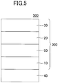
- the gasochromic light control element which further includes the base material on the surface of the hydrogen occlusion body according to the first embodiment of the present invention, has been described above, a gasochromic light control element that further includes a base material on the surface of the hydrogen occlusion body according to the second embodiment of the present invention may be used. That is, as illustrated in FIG. 5 , a gasochromic light control element 500 in which the base material 40 is provided on at least a part of the surface of the hydrogen occlusion layer 10 that is opposite to the catalyst layer 20 of the hydrogen sensing element 300 may be used.
- the hydrogen sensor according to the fourth embodiment of the present invention has a configuration similar to that of the gasochromic light control element according to the third embodiment of the present invention, and further includes a base material on the surface of the hydrogen occlusion body according to the first embodiment of the present invention.
- the hydrogen occlusion body according to the first embodiment of the present invention has a function of reversibly changing in an optical property upon hydrogenation and dehydrogenation.
- the hydrogen sensor according to the fourth embodiment of the present invention can sense hydrogen in the atmosphere.
- a hydrogen sensor has a configuration similar to that of the gasochromic light control element 400 (see FIG. 4 )
- a method of detecting a change in optical transmittance or optical reflectance of the hydrogen occlusion layer 10 for example, it is possible to use a method of detecting reflected light or transmitted light from the base material 40 side or the catalyst layer 20 side.
- a material constituting the base material 40 is desirably transparent to light used for detection, that is, a material constituting the base material 40 desirably does not inhibit transmission of light used for detection.
- the optical property of the base material 40 is not particularly limited.
- a material constituting the base material 40 in a case of a hydrogen sensor that detects visible light as transmitted light or reflected light from the base material 40 side is not particularly limited as long as being a material that transmits visible light, for example, it is preferable to use glass or plastic as the material constituting the base material 40.
- PET polyethylene terephthalate
- PEN polyethylene naphthalate
- nylon polyethylene naphthalate
- acrylic acrylic
- the diffusion prevention layer 50 may not be inserted between the hydrogen occlusion layer 10 and the catalyst layer 20.
- the hydrogen sensor which further includes the base material on the surface of the hydrogen occlusion body according to the first embodiment of the present invention
- a hydrogen sensor that further includes a base material on the surface of the hydrogen occlusion body according to the second embodiment of the present invention may be used. That is, a configuration similar to that of the gasochromic light control element 500 (see FIG. 5 ) may be used.
- a hydrogen sensing element according to a fifth embodiment of the present invention has a configuration similar to that of the gasochromic light control element according to the third embodiment of the present invention, a description of the fifth embodiment will not be provided.
- a gasochromic light control element 400 that includes a hydrogen occlusion body 200, in which a hydrogen occlusion layer 10 made of a magnesium-yttrium alloy, a diffusion prevention layer 50 made of tantalum, and a catalyst layer 20 made of a palladium-ruthenium alloy are sequentially stacked on a glass substrate as a base material 40, was prepared.
- a magnesium-yttrium alloy thin film (hydrogen occlusion layer 10) having a film thickness of 50 nm
- a tantalum thin film having a film thickness of 2 nm
- a palladium-ruthenium alloy thin film (catalyst layer 20) having a film thickness of 3 nm with a composition ratio changed were sequentially deposited.
- the glass substrate was set in a vacuum apparatus, and the inside of the chamber is evacuated.
- a magnesium-yttrium alloy thin film (hydrogen occlusion layer 10) that is represented by a composition formula Mg 0.4 Y 0.6 was deposited.
- sputtering was carried out by setting the argon gas pressure in the sputtering to 0.3 Pa and applying it to each target for a predetermined time by a DC sputtering method.
- composition ratio of the magnesium-yttrium alloy thin film (hydrogen occlusion layer 10) to be deposited can be controlled based on the electric power applied to the respective targets.
- film thickness of the magnesium-yttrium alloy thin film (hydrogen occlusion layer 10) to be deposited can be controlled based on the duration by which power is applied to the targets.
- the tantalum thin film (diffusion prevention layer 50) was deposited by applying 20 W of power to the target of metallic tantalum.
- a gasochromic light control element 400 including a hydrogen occlusion body 200 was prepared similarly to Examples 1 to 9.
- Table 1 indicates, for each of Examples 1 to 9 and Comparative Example, the power applied to the targets when depositing the catalyst layer 20 in the gasochromic light control element 400, the composition ratio of the catalyst layer 20, and the film thickness.
- Table 1 CATALYST LAYER 20 POWER [W] COMPOSITION RATIO Pd Ru Example 1 27.0 4.5 Pd 0.90 Ru 0.10 Example 2 24.0 9.0 Pd 0.80 Ru 0.20 Example 3 21.0 13.5 Pd 0.70 Ru 0.30 Example 4 18.0 18.0 Pd 0.60 Ru 0.40 Example 5 15.0 22.5 Pd 0.50 Ru 0.50 Example 6 12.0 27.0 Pd 0.40 Ru 0.60 Example 7 9.0 31.5 Pd 0.30 Ru 0.70 Example 8 6.0 36.0 Pd 0.20 Ru 0.80 Example 9 3.0 40.5 Pd 0.10 Ru 0.90 Comparative Example 1 30.0 0.0 Pd
- the gasochromic light control elements 400 prepared by the procedure as described above were in a reflective state of metallic luster. Furthermore, even when left in the atmosphere for 500 hours, the gasochromic light control elements 400 were similarly in a reflective state of metallic luster.
- hydrogen-containing gas hydrogen gas of 1 atm diluted with argon to be at 4 vol%
- the period of time to become the transparent state by occluding hydrogen, that is, by hydrogenation, and the period of time to become the reflective state by releasing hydrogen, that is, by dehydrogenation were greatly changed due to the composition ratio of the palladium-ruthenium alloy.
- the optical transmittance of the gasochromic light control element 400 was measured.
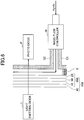
- a glass plate G1 having a thickness of 1 mm was attached to the gasochromic light control element 400 via a spacer S.
- a flow of a predetermined amount of hydrogen-containing gas was performed for 95 seconds by a mass flow controller M in the gap between the glass plate G1 and the glass plate G2 having a thickness of 1 mm, and the flow of the hydrogen-containing gas was stopped for sixty minutes.
- the flow control of the hydrogen-containing gas with this operation as one cycle was repeated for a predetermined number of times, during which the optical transmittance was measured every 2 seconds.
- a light source a light emitting diode L having a wavelength of 940 nm was used, and as a light receiving element, a photodiode P was used.
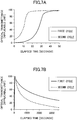
- FIG. 7A, FIG. 7B , FIG. 8A, FIG. 8B , FIG. 9A, and FIG. 9B illustrate measured results of the optical transmittances of the gasochromic light control elements 400 of Comparative Example 1 and Examples 2 and 4.
- a and B are respectively the case in which the state changes from the reflective state to the transparent state and the case in which the state changes from the transparent state to the reflective state.
- the elapsed time means a time elapsed from the start or stop of the flow of the hydrogen-containing gas.
- the optical transmittance other than that when changing from the reflective state to the transparent state in the first cycle was normalized such that the lowest value among the optical transmittance values of eight times reflective states excluding the optical transmittance of the reflective state immediately after deposition was 0 [applicable unit] and the optical transmittance that become constant in the transparent state was 100 [applicable unit].
- the optical transmittance when changing from the reflective state to the transparent state in the first cycle was normalized such that the optical transmittance immediately after deposition was 0 [applicable unit] and the optical transmittance that become constant in the transparent state was 100 [applicable unit].
- FIG. 7A, FIG. 7B , FIG. 8A, FIG. 8B , FIG. 9A, and FIG. 9B that in the gasochromic light control elements 400 of Comparative Example 1 and Examples 2 and 4, the switching time is shorter in the second cycle than in the first cycle. Furthermore, it can be seen that in the gasochromic light control elements 400 of and Examples 2 and 4, the switching time from the reflective state to the transparent state and the switching time from the transparent state to the reflective state are shorter than those of the gasochromic light control element 400 of Comparative Example 1.
- the time from the start of the flow of hydrogen-containing gas to when the optical transmittance has reached 90 [applicable unit] is defined as the switching time from the reflective state to the transparent state.
- the time from the stop of the flow of hydrogen-containing gas to when the optical transmittance has reached 10 [applicable unit] is defined as the switching time from the transparent state to the reflective state.
- FIG. 10 and FIG. 11 respectively illustrate the relationship between the switching time from the reflective state to the transparent state and x in the composition formula described above and the relationship between the switching time from the transparent state to the reflective state and x in the composition formula described above.
Landscapes
- Chemical & Material Sciences (AREA)
- Physics & Mathematics (AREA)
- Engineering & Computer Science (AREA)
- Organic Chemistry (AREA)
- General Physics & Mathematics (AREA)
- Health & Medical Sciences (AREA)
- Life Sciences & Earth Sciences (AREA)
- Chemical Kinetics & Catalysis (AREA)
- Nonlinear Science (AREA)
- Biochemistry (AREA)
- Pathology (AREA)
- Analytical Chemistry (AREA)
- Immunology (AREA)
- General Health & Medical Sciences (AREA)
- Combustion & Propulsion (AREA)
- Materials Engineering (AREA)
- Optics & Photonics (AREA)
- Inorganic Chemistry (AREA)
- Food Science & Technology (AREA)
- Medicinal Chemistry (AREA)
- Plasma & Fusion (AREA)
- Electrochromic Elements, Electrophoresis, Or Variable Reflection Or Absorption Elements (AREA)
- Investigating Or Analysing Materials By The Use Of Chemical Reactions (AREA)
- Hydrogen, Water And Hydrids (AREA)
- Catalysts (AREA)
Abstract
Description
- The present invention relates to a hydrogen occlusion body, a gasochromic light control element, a hydrogen sensing element, and a hydrogen sensor.
- A hydrogen occlusion body that includes a hydrogen occlusion layer whose optical property reversibly changes upon hydrogenation and dehydrogenation; and a catalyst layer that promotes the hydrogenation and the dehydrogenation of the hydrogen occlusion layer can be used at ambient temperatures and ambient pressures.
- Thus, a hydrogen occlusion body as described above can be used for a gasochromic light control element that can control inflow and outflow of light and heat (see, for example, Patent Documents 1 to 5), a hydrogen sensing element (see, for example, Patent Documents 6 and 7), and a hydrogen sensor (for example, see Patent Documents 8 and 9).
- As a material constituting the catalyst layer, palladium and platinum are known (for example, see Patent Document 1).
- Also, as a material constituting the hydrogen occlusion layer, tungsten oxide, a rare-earth element, an alloy of magnesium and a rare-earth metal, and an alloy of magnesium and a transition metal are known (for example, see Patent Documents 2 to 7).
-
- [Patent Document 1]
US Patent No. 5635729 - [Patent Document 2]
US Patent No. 5905590 - [Patent Document 3]
US Patent No. 6647166 - [Patent Document 4] Japanese Laid-open Patent Publication No.
2010-66747 - [Patent Document 5] Japanese Laid-open Patent Publication No.
2013-83911 - [Patent Document 6] Japanese Laid-open Patent Publication No.
2011-219841 - [Patent Document 7] Japanese Laid-open Patent Publication No.
2013-245370 - [Patent Document 8]
US Patent No. 6006582 - [Patent Document 9]
US Patent No. 6596236 - However, hydrogen occlusion bodies as described above have a problem that the production cost is high because a material constituting a catalyst layer is very expensive.
- In view of the above, an object in one aspect of the present invention is to reduce production cost and to provide a hydrogen occlusion body that can be used at ambient temperatures and ambient pressures.
- In one aspect of the present invention, a hydrogen occlusion body includes: a hydrogen occlusion layer containing a material whose optical property reversibly changes upon hydrogenation and dehydrogenation; and a catalyst layer containing a palladium-ruthenium alloy.
- According to one aspect of the present invention, it is possible to reduce production cost and to provide a hydrogen occlusion body that can be used at ambient temperatures and ambient pressures.
-
-
FIG. 1 is a cross-sectional view illustrating an example configuration of a hydrogen occlusion body according to a first embodiment of the present invention; -
FIG. 2 is a cross-sectional view illustrating a modified example of a hydrogen occlusion body according to the first embodiment of the present invention; -
FIG. 3 is a cross-sectional view illustrating an example configuration of a hydrogen occlusion body according to a second embodiment of the present invention; -
FIG. 4 is a cross-sectional view illustrating a configuration example of a gasochromic light control element according to a third embodiment of the present invention; -
FIG. 5 is cross-sectional view illustrating a modified example of a gasochromic light control element according to the third embodiment of the present invention; -
FIG. 6 is cross-sectional view illustrating a configuration of a measurement apparatus of optical transmittance; -
FIG. 7A is diagram illustrating a measurement result of optical transmittance of a gasochromic light control element of Comparative Example 1; -
FIG. 7B is diagram illustrating the measured result of optical transmittance of the gasochromic light control element of Comparative Example 1; -
FIG. 8A is diagram illustrating the measured result of optical transmittance of a gasochromic light control element of Example 2; -
FIG. 8B is diagram illustrating the measured result of optical transmittance of the gasochromic light control element of Example 2; -
FIG. 9A is diagram illustrating the measured result of optical transmittance of a gasochromic light control element of Example 4; -
FIG. 9B is diagram illustrating the measured result of optical transmittance of the gasochromic light control element of Example 4; -
FIG. 10 is a diagram illustrating the relationship of a switching time from a reflective state to a transparent state with respect to a composition ratio of a palladium-ruthenium alloy; and -
FIG. 11 is a diagram illustrating the relationship between a switching time from the transparent state to the reflective state with respect to the composition ratio of the palladium-ruthenium alloy. - In the following, embodiments for carrying out the present invention will be described with reference to the drawings. However, the present invention is not limited to the following embodiments, and various modifications and substitutions can be made with respect to the following embodiments without departing from the scope of the present invention.
- In the present embodiment, a hydrogen occlusion body according to a first embodiment of the present invention will be described. The hydrogen occlusion body according to the first embodiment of the present invention includes a hydrogen occlusion layer containing a material whose optical property reversibly changes upon hydrogenation and dehydrogenation (hereinafter referred to as "hydrogen occlusion material"), and a catalyst layer containing a palladium-ruthenium alloy.
-
FIG. 1 illustrates a configuration example of a hydrogen occlusion body according to the first embodiment of the present invention. - The
hydrogen occlusion body 100 includes ahydrogen occlusion layer 10 and acatalyst layer 20. - The
hydrogen occlusion layer 10 contains a hydrogen occlusion material, and thecatalyst layer 20 contains a palladium-ruthenium alloy. Therefore, thehydrogen occlusion body 100 can be used at ambient temperatures and ambient pressures. - Here, the price of ruthenium is about one tenth of that of palladium. Therefore, the
hydrogen occlusion body 100 including thecatalyst layer 20 containing the palladium-ruthenium alloy can reduce production cost as compared with a hydrogen occlusion body including a catalyst layer containing palladium. - The palladium-ruthenium alloy contained in the
catalyst layer 20 promotes the hydrogenation and dehydrogenation of the hydrogen occlusion material contained in thehydrogen occlusion layer 10. Therefore, by thecatalyst layer 20, it is possible to decrease the time required for changing the optical property of thehydrogen occlusion layer 10, that is, the switching time. Note that thecatalyst layer 20 may further contain an element other than the palladium/ruthenium alloy as a minor component (inevitable component). - Next, the palladium-ruthenium alloy will be explained.
- Although the palladium-ruthenium alloy is inexpensive as the composition ratio of ruthenium is larger, the composition ratio of ruthenium is not particularly limited.
- In terms of shortening the switching time in a case of storing in the atmosphere for a long time, the palladium-ruthenium alloy is preferably a compound that is represented by the general formula (1) Pd1-xRux (0.1 < x < 0.7), and is more preferably a compound that is represented by the general formula (2) Pd1-xRux (0.15 < x < 0.55).
- The thickness of the
catalyst layer 20 is appropriately selected depending on a reactivity of thehydrogen occlusion layer 10 and a catalytic ability of the palladium-ruthenium alloy, and is not particularly limited. It is preferable that thickness of thecatalyst layer 20 is greater than or equal to 1 nm and less than or equal to 20 nm. When the thickness of thecatalyst layer 20 is greater than or equal to 1 nm, the function of thecatalyst layer 20 can be enhanced. On the other hand, when the thickness of thecatalyst layer 20 is less than or equal to 20 nm, the optical transmittance of thecatalyst layer 20 can be enhanced. - A method of forming the
catalyst layer 20 is not particularly limited. For example, as the method of forming thecatalyst layer 20, a general deposition method such as a sputtering method, a vacuum vapor deposition method, an electron beam vapor deposition method, a chemical vapor deposition (CVD) method, a plating method, or a sol-gel method may be used. - It is preferable that the
hydrogen occlusion layer 10 contains a hydrogen occlusion material whose optical property reversibly changes upon hydrogenation and dehydrogenation at ambient temperatures and ambient pressures. - Next, the hydrogen occlusion material will be described.
- The hydrogen occlusion material is not particularly limited as long as it is a material whose optical property reversibly changes upon hydrogenation and dehydrogenation.
- Specifically, the hydrogen occlusion material may be a material having a chromic property that reversibly changes in an optical property upon hydrogenation and dehydrogenation.
- As the hydrogen occlusion material, it is preferable to use a metal oxide, an organic polymer, or a metal complex whose state reversibly changes between a colored state and a transparent state upon hydrogenation and dehydrogenation, or an alloy or a hydride of a rare earth metal whose state reversibly changes between a transparent state upon hydrogenation and a reflective state (metal state) upon dehydrogenation.
- Examples of metal oxides include tungsten oxide, molybdenum oxide, vanadium oxide, nickel oxide, titanium dioxide, iridium oxide, and the like.
- Examples of organic polymers include polyaniline, PEDOT-PSS, polypyrrole, and the like.
- Examples of metal complexes include a Prussian blue type complex and the like.
- Examples of alloys include a rare earth metal-magnesium alloy such as a Y-Mg alloy, a La-Mg alloy, a Gd-Mg alloy, or a Sm-Mg alloy, a magnesium-transition metal alloy such as a Mg-Ni alloy, a Mg-Mn alloy, a Mg-Co alloy, or a Mg-Fe alloy, an alloy containing at least one element selected from elements in group 2 and two or more elements selected from elements in group 3 and rare earth elements, and the like.
- Examples of hydrides of a rare earth metal include YH2, LaH2, GdH2, SmH2, and the like.
- Note that the
hydrogen occlusion layer 10 may further contain an element other than the hydrogen occluding material as a minor component (inevitable component). - Also, as illustrated in
FIG. 2 , adiffusion prevention layer 50 may be inserted between thehydrogen occlusion layer 10 and thecatalyst layer 20 to form ahydrogen occlusion body 200. - A material constituting the
diffusion prevention layer 50 is not particularly limited as long as it is able to prevent the palladium-ruthenium alloy from diffusing into thehydrogen occlusion layer 10 and being able to effectively diffuse hydrogen, which has passed through thecatalyst layer 20, into thehydrogen occlusion layer 10. It is preferable to use, as a material constituting thediffusion prevention layer 50, niobium, vanadium, titanium or tantalum. - A method of forming the
diffusion prevention layer 50 is not particularly limited. For example, as the method of forming thediffusion prevention layer 50, a general deposition method such as a sputtering method, a vacuum vapor deposition method, an electron beam vapor deposition method, a chemical vapor deposition (CVD) method, a plating method, or a sol-gel method can be used. - As described above, the
hydrogen occlusion bodies - Then, the
hydrogen occlusion bodies hydrogen occlusion bodies hydrogen occlusion bodies hydrogen occlusion bodies hydrogen occlusion bodies - In the present embodiment, a hydrogen occlusion body according to a second embodiment of the present invention will be described.
- The hydrogen occlusion body according to the second embodiment of the present invention further includes a protective layer on the surface of the hydrogen occlusion body according to the first embodiment.
-
FIG. 3 illustrates a configuration example of the hydrogen occlusion body according to the second embodiment of the present invention. - The
hydrogen occlusion body 300 further includes aprotective layer 30 on the surface of thehydrogen occlusion body 200. - Because the configuration of the
hydrogen sensing element 300 other than theprotective layer 30 is similar to that of thehydrogen occlusion body 200, the description of thehydrogen sensing element 300 other than theprotective layer 30 is omitted. - The
hydrogen occlusion body 300 includes theprotective layer 30 on at least a part of the surface of thecatalyst layer 20 that is opposite to thehydrogen occlusion layer 10. - The
protective layer 30 is a layer that is permeable to hydrogen, but impermeable to water and has a function of preventing, in cooperation with thecatalyst layer 20, thehydrogen occlusion layer 10 from being oxidized by water or oxygen. - Although the
catalyst layer 20 also has a function of preventing thehydrogen occlusion layer 10 from being oxidized, by forming theprotective layer 30, the function of preventing thehydrogen occlusion layer 10 from being oxidized can be enhanced. - Further, the
protective layer 30 has a function of preventing thecatalyst layer 20 from being oxidized by water or oxygen. - A material constituting the
protective layer 30 is not particularly limited as long as having permeability (hydrogen permeability) to hydrogen (hydrogen ions) and impermeability to water. Examples of the material constituting theprotective layer 30 include a polymer such as fluororesin, polyvinyl acetate, polyvinyl chloride, polystyrene, and cellulose acetate, an inorganic material such as titanium dioxide, and the like. - For example, as a method of forming the
protective layer 30, a general deposition method such as a drying method after applying a dispersion liquid in which a polymer is dispersed, a sputtering method, or a vacuum vapor deposition method for depositing an inorganic thin film can be used. - By forming the
protective layer 30, thecatalyst layer 20 and thehydrogen occlusion layer 10 can be prevented from being oxidized by water and oxygen. Therefore, it is possible to prevent deterioration of thecatalyst layer 20 and thehydrogen occlusion layer 10 and to enhance durability. - Note that similarly to the
hydrogen occlusion body 100, thediffusion prevention layer 50 may not be inserted between thehydrogen occlusion layer 10 and thecatalyst layer 20. - In the present embodiment, a gasochromic light control element according to a third embodiment of the present invention will be described.
- The gasochromic light control element according to the third embodiment of the present invention further includes a base material on the surface of the hydrogen occlusion body according to the first embodiment of the present invention.
- The hydrogen occlusion body according to the first embodiment of the present invention has a function of reversibly changing in an optical property upon hydrogenation and dehydrogenation.
- Therefore, by a change in the surrounding atmosphere, the gasochromic light control element according to the third embodiment of the present invention hydrogenates or dehydrogenates, that is, occludes or releases hydrogen. Thereby, the gasochromic light control element according to the third embodiment of the present invention can control inflow or outflow of light and heat by changing optical transmittance or optical reflectance of the hydrogen occlusion material.
-
FIG. 4 illustrates a configuration example of a gasochromic light control element according to the third embodiment of the present invention. - The gasochromic
light control element 400 further includes abase material 40 on the surface of thehydrogen occlusion body 200. - Note that since the configuration of the gasochromic
light control element 400 other than thebase material 40 is similar to that of thehydrogen occlusion body 200, the description of the gasochromiumlight control element 400 other than thebase material 40 is omitted. - The gasochromic
light control element 400 includes thebase material 40 on at least a part of the surface of thehydrogen occlusion layer 10 of thehydrogen occlusion body 200 that is opposite to thecatalyst layer 20. - Although a material constituting the
base material 40 is not particularly limited as long as it is a material that transmits visible light, for example, it is preferable to use glass or plastic as the material constituting thebase material 40. - Here, it is preferable to use polyethylene terephthalate (PET), polyethylene naphthalate (PEN), nylon, or acrylic as the plastic.
- Note that similarly to the
hydrogen occlusion body 100, thediffusion prevention layer 50 may not be inserted between thehydrogen occlusion layer 10 and thecatalyst layer 20. Although the gasochromic light control element, which further includes the base material on the surface of the hydrogen occlusion body according to the first embodiment of the present invention, has been described above, a gasochromic light control element that further includes a base material on the surface of the hydrogen occlusion body according to the second embodiment of the present invention may be used. That is, as illustrated inFIG. 5 , a gasochromiclight control element 500 in which thebase material 40 is provided on at least a part of the surface of thehydrogen occlusion layer 10 that is opposite to thecatalyst layer 20 of thehydrogen sensing element 300 may be used. - In the present embodiment, a hydrogen sensor according to a fourth embodiment of the present invention will be described.
- The hydrogen sensor according to the fourth embodiment of the present invention has a configuration similar to that of the gasochromic light control element according to the third embodiment of the present invention, and further includes a base material on the surface of the hydrogen occlusion body according to the first embodiment of the present invention.
- The hydrogen occlusion body according to the first embodiment of the present invention has a function of reversibly changing in an optical property upon hydrogenation and dehydrogenation.
- Therefore, by measuring a change in optical transmittance or optical reflectance of the hydrogen occlusion body that occludes or release hydrogen due to a change in the surrounding atmosphere, the hydrogen sensor according to the fourth embodiment of the present invention can sense hydrogen in the atmosphere.
- For example, in a case where a hydrogen sensor has a configuration similar to that of the gasochromic light control element 400 (see
FIG. 4 ), as a method of detecting a change in optical transmittance or optical reflectance of thehydrogen occlusion layer 10, for example, it is possible to use a method of detecting reflected light or transmitted light from thebase material 40 side or thecatalyst layer 20 side. - In a case of a hydrogen sensor that detects transmitted light or reflected light from the
base material 40 side, a material constituting thebase material 40 is desirably transparent to light used for detection, that is, a material constituting thebase material 40 desirably does not inhibit transmission of light used for detection. - However, in a case of a hydrogen sensor that detects reflected light from the
catalyst layer 20 side, the optical property of thebase material 40 is not particularly limited. - Although a material constituting the
base material 40 in a case of a hydrogen sensor that detects visible light as transmitted light or reflected light from thebase material 40 side is not particularly limited as long as being a material that transmits visible light, for example, it is preferable to use glass or plastic as the material constituting thebase material 40. - Here, it is preferable to use polyethylene terephthalate (PET), polyethylene naphthalate (PEN), nylon, or acrylic as the plastic.
- Note that similarly to the
hydrogen occlusion body 100, thediffusion prevention layer 50 may not be inserted between thehydrogen occlusion layer 10 and thecatalyst layer 20. - Although the hydrogen sensor, which further includes the base material on the surface of the hydrogen occlusion body according to the first embodiment of the present invention, has been described above, a hydrogen sensor that further includes a base material on the surface of the hydrogen occlusion body according to the second embodiment of the present invention may be used. That is, a configuration similar to that of the gasochromic light control element 500 (see
FIG. 5 ) may be used. - Since a hydrogen sensing element according to a fifth embodiment of the present invention has a configuration similar to that of the gasochromic light control element according to the third embodiment of the present invention, a description of the fifth embodiment will not be provided.
- In the following, the present invention will be described in detail with reference to Examples, but the present invention is not limited to Examples.
- For each of following Examples, a gasochromic
light control element 400 that includes ahydrogen occlusion body 200, in which ahydrogen occlusion layer 10 made of a magnesium-yttrium alloy, adiffusion prevention layer 50 made of tantalum, and acatalyst layer 20 made of a palladium-ruthenium alloy are sequentially stacked on a glass substrate as abase material 40, was prepared. - Specifically, on the glass substrate (base material 40) having a thickness of 1 mm, a magnesium-yttrium alloy thin film (hydrogen occlusion layer 10) having a film thickness of 50 nm, a tantalum thin film (diffusion prevention layer 50) having a film thickness of 2 nm, a palladium-ruthenium alloy thin film (catalyst layer 20) having a film thickness of 3 nm with a composition ratio changed were sequentially deposited.
- Next, deposition conditions of the
hydrogen occlusion layer 10, thediffusion prevention layer 50, and thecatalyst layer 20 will be described. When depositing the magnesium-yttrium alloy thin film of thehydrogen occlusion layer 10, the tantalum thin film of thediffusion prevention layer 50, and the palladium-ruthenium alloy thin film of thecatalyst layer 20, a magnetron sputtering equipment with multi-targets was used. At this time, for five sputter guns, metallic magnesium, metallic yttrium, metallic tantalum, metallic palladium and metallic ruthenium were respectively set as targets. - First, after cleaning the glass substrate (base material 40), the glass substrate was set in a vacuum apparatus, and the inside of the chamber is evacuated.
- Next, by simultaneously applying power of 10 W and 30 W to the respective targets of metallic magnesium and metallic yttrium, a magnesium-yttrium alloy thin film (hydrogen occlusion layer 10) that is represented by a composition formula Mg0.4Y0.6 was deposited. At this time, sputtering was carried out by setting the argon gas pressure in the sputtering to 0.3 Pa and applying it to each target for a predetermined time by a DC sputtering method.
- Note that the composition ratio of the magnesium-yttrium alloy thin film (hydrogen occlusion layer 10) to be deposited can be controlled based on the electric power applied to the respective targets. Also, the film thickness of the magnesium-yttrium alloy thin film (hydrogen occlusion layer 10) to be deposited can be controlled based on the duration by which power is applied to the targets.
- Next, under the same vacuum condition as the deposition of the
hydrogen occlusion layer 10, the tantalum thin film (diffusion prevention layer 50) was deposited by applying 20 W of power to the target of metallic tantalum. - Next, by simultaneously applying power to the targets of metallic palladium and metallic ruthenium, a palladium-ruthenium alloy thin film (catalyst layer 20) that is represented by a composition formula Pd1-xRux (x = 0.1, 0.2, 0.3, 0.4, 0.5, 0.6, 0.7, 0.8, 0.9) was deposited to prepare the gasochromic
light control element 400 including thehydrogen occlusion body 200 for each of Examples 1 to 9. - With the exception of applying power only to metallic palladium to make x = 0, that is, a palladium thin film (catalyst layer 20) was formed, a gasochromic
light control element 400 including ahydrogen occlusion body 200 was prepared similarly to Examples 1 to 9. - Table 1 indicates, for each of Examples 1 to 9 and Comparative Example, the power applied to the targets when depositing the
catalyst layer 20 in the gasochromiclight control element 400, the composition ratio of thecatalyst layer 20, and the film thickness.Table 1 CATALYST LAYER 20POWER [W] COMPOSITION RATIO Pd Ru Example 1 27.0 4.5 Pd0.90Ru0.10 Example 2 24.0 9.0 Pd0.80Ru0.20 Example 3 21.0 13.5 Pd0.70Ru0.30 Example 4 18.0 18.0 Pd0.60Ru0.40 Example 5 15.0 22.5 Pd0.50Ru0.50 Example 6 12.0 27.0 Pd0.40Ru0.60 Example 7 9.0 31.5 Pd0.30Ru0.70 Example 8 6.0 36.0 Pd0.20Ru0.80 Example 9 3.0 40.5 Pd0.10Ru0.90 Comparative Example 1 30.0 0.0 Pd - The gasochromic
light control elements 400 prepared by the procedure as described above were in a reflective state of metallic luster. Furthermore, even when left in the atmosphere for 500 hours, the gasochromiclight control elements 400 were similarly in a reflective state of metallic luster. Upon exposing the surface of the palladium-ruthenium alloy thin film to hydrogen gas of 1 atm diluted with argon to be at 4 vol% (hereinafter referred to as "hydrogen-containing gas"), the state changed to a transparent state by the magnesium-yttrium alloy thin film occluding hydrogen, that is, by hydrogenation. In this state, upon exposing the surface of the palladium-ruthenium alloy thin film to the atmosphere, the state returned to the reflective state by releasing hydrogen, that is, by dehydrogenation. As described above, the optical property of the gasochromiclight control elements 400 changed due to occlusion and release of hydrogen at ambient temperatures and normal pressures, that is, due to hydrogenation and dehydrogenation. - On the other hand, the period of time to become the transparent state by occluding hydrogen, that is, by hydrogenation, and the period of time to become the reflective state by releasing hydrogen, that is, by dehydrogenation were greatly changed due to the composition ratio of the palladium-ruthenium alloy.
- After the gasochromic
light control element 400 was left in the atmosphere for 500 hours, the optical transmittance of the gasochromiclight control element 400 was measured. - Specifically, as illustrated in
FIG. 6 , a glass plate G1 having a thickness of 1 mm was attached to the gasochromiclight control element 400 via a spacer S. Next, after a flow of a predetermined amount of hydrogen-containing gas was performed for 95 seconds by a mass flow controller M in the gap between the glass plate G1 and the glass plate G2 having a thickness of 1 mm, and the flow of the hydrogen-containing gas was stopped for sixty minutes. When the flow of the hydrogen-containing gas is stopped, air flows into the gap between the two glass plates G1 and G2 from an opening portion. The flow control of the hydrogen-containing gas with this operation as one cycle was repeated for a predetermined number of times, during which the optical transmittance was measured every 2 seconds. As a light source, a light emitting diode L having a wavelength of 940 nm was used, and as a light receiving element, a photodiode P was used. -
FIG. 7A, FIG. 7B ,FIG. 8A, FIG. 8B ,FIG. 9A, and FIG. 9B illustrate measured results of the optical transmittances of the gasochromiclight control elements 400 of Comparative Example 1 and Examples 2 and 4. Here, A and B are respectively the case in which the state changes from the reflective state to the transparent state and the case in which the state changes from the transparent state to the reflective state. - Note that in
FIG. 7A, FIG. 7B ,FIG. 8A, FIG. 8B ,FIG. 9A, and FIG. 9B , the elapsed time means a time elapsed from the start or stop of the flow of the hydrogen-containing gas. - Also, the optical transmittance other than that when changing from the reflective state to the transparent state in the first cycle was normalized such that the lowest value among the optical transmittance values of eight times reflective states excluding the optical transmittance of the reflective state immediately after deposition was 0 [applicable unit] and the optical transmittance that become constant in the transparent state was 100 [applicable unit].
- However, the optical transmittance when changing from the reflective state to the transparent state in the first cycle was normalized such that the optical transmittance immediately after deposition was 0 [applicable unit] and the optical transmittance that become constant in the transparent state was 100 [applicable unit].
- It can be seen from
FIG. 7A, FIG. 7B ,FIG. 8A, FIG. 8B ,FIG. 9A, and FIG. 9B that in the gasochromiclight control elements 400 of Comparative Example 1 and Examples 2 and 4, the switching time is shorter in the second cycle than in the first cycle. Furthermore, it can be seen that in the gasochromiclight control elements 400 of and Examples 2 and 4, the switching time from the reflective state to the transparent state and the switching time from the transparent state to the reflective state are shorter than those of the gasochromiclight control element 400 of Comparative Example 1. - Here, the time from the start of the flow of hydrogen-containing gas to when the optical transmittance has reached 90 [applicable unit] is defined as the switching time from the reflective state to the transparent state. Also, the time from the stop of the flow of hydrogen-containing gas to when the optical transmittance has reached 10 [applicable unit] is defined as the switching time from the transparent state to the reflective state.
-
FIG. 10 and FIG. 11 respectively illustrate the relationship between the switching time from the reflective state to the transparent state and x in the composition formula described above and the relationship between the switching time from the transparent state to the reflective state and x in the composition formula described above. - Note that in
FIG. 10 and FIG. 11 , because the switching time of x = 0.9 was 3600 seconds or more, the switching time of x = 0.9 is omitted. - Also, in
FIG. 11 , because the switching times of x = 0.6 and 0.8 in the first cycle and the second cycle were 3600 seconds or more, they are omitted. - It can been seen from
FIG. 10 and FIG. 11 , that the switching time is short when the formula 0.1 < x < 0.7 is satisfied. It is considered that this is because, by alloying with ruthenium, the catalytic action of palladium is not degraded even being left in the atmosphere. - The present international application is based on and claims priority to Japanese Patent Application No.
2016-185565, filed on September 23, 2016 2016-185565 -
- 10
- Hydrogen occlusion layer
- 20
- catalyst layer
- 30
- Protective layer
- 40
- Base material
- 50
- Diffusion prevention layer
- 100, 200, 300
- Hydrogen occlusion body
- 400, 500
- gasochromic light control element
Claims (8)
- A hydrogen occlusion body comprising:a hydrogen occlusion layer containing a material whose optical property reversibly changes upon hydrogenation and dehydrogenation; anda catalyst layer containing a palladium-ruthenium alloy.
- The hydrogen occlusion body according to claim 1, wherein the palladium-ruthenium alloy is represented by a general formula Pd1-xRux (0.1 < x < 0.7).
- The hydrogen occlusion body according to claim 1, wherein a thickness of the catalyst layer is greater than or equal to 1 nm and less than or equal to 20 nm.
- The hydrogen occlusion body according to claim 1, further comprising:
a diffusion prevention layer that is provided between the hydrogen occlusion layer and the catalyst layer. - The hydrogen occlusion body according to claim 1, further comprising:
a protective layer provided opposite the hydrogen occlusion layer with respect to the catalyst layer. - A gasochromic light control element comprising:
the hydrogen occlusion body according to claim 1. - A hydrogen sensing element comprising the hydrogen occlusion body according to claim 1.
- A hydrogen sensor comprising the hydrogen occlusion body according to claim 1.
Applications Claiming Priority (2)
| Application Number | Priority Date | Filing Date | Title |
|---|---|---|---|
| JP2016185565 | 2016-09-23 | ||
| PCT/JP2017/029127 WO2018055946A1 (en) | 2016-09-23 | 2017-08-10 | Hydrogen storage body, gaschromic dimming element, hydrogen sensing element, and hydrogen sensor |
Publications (3)
| Publication Number | Publication Date |
|---|---|
| EP3517495A1 true EP3517495A1 (en) | 2019-07-31 |
| EP3517495A4 EP3517495A4 (en) | 2020-04-22 |
| EP3517495B1 EP3517495B1 (en) | 2021-06-16 |
Family
ID=61689410
Family Applications (1)
| Application Number | Title | Priority Date | Filing Date |
|---|---|---|---|
| EP17852727.1A Active EP3517495B1 (en) | 2016-09-23 | 2017-08-10 | Hydrogen storage body, gasochromic dimming element, hydrogen sensing element, and hydrogen sensor |
Country Status (6)
| Country | Link |
|---|---|
| US (1) | US11016359B2 (en) |
| EP (1) | EP3517495B1 (en) |
| JP (1) | JP6715500B2 (en) |
| KR (1) | KR20190040986A (en) |
| CN (1) | CN109715552B (en) |
| WO (1) | WO2018055946A1 (en) |
Families Citing this family (4)
| Publication number | Priority date | Publication date | Assignee | Title |
|---|---|---|---|---|
| CN111118330B (en) * | 2019-12-16 | 2021-05-04 | 北京凯恩特技术有限公司 | Palladium-based ternary alloy hydrogen sensitive material, film, element and preparation method, hydrogen sensor |
| JP7354989B2 (en) * | 2020-10-30 | 2023-10-03 | トヨタ自動車株式会社 | Composite alloy manufacturing method and electrode manufacturing method |
| WO2022211541A1 (en) * | 2021-03-31 | 2022-10-06 | 한국화학연구원 | Hydrogen gas sensor and manufacturing method therefor |
| JP7853676B2 (en) * | 2022-04-27 | 2026-04-30 | 国立研究開発法人産業技術総合研究所 | Hydrogen detection element, hydrogen sensor, dimming component, and dimming window |
Family Cites Families (18)
| Publication number | Priority date | Publication date | Assignee | Title |
|---|---|---|---|---|
| US4132668A (en) * | 1977-04-06 | 1979-01-02 | Gryaznov Vladimir M | Method of preparing a hydrogen-permeable membrane catalyst on a base of palladium or its alloys for the hydrogenation of unsaturated organic compounds |
| JPH0665987B2 (en) | 1982-11-19 | 1994-08-24 | 富士写真フイルム株式会社 | Analysis element |
| WO1996038758A1 (en) | 1995-05-30 | 1996-12-05 | Philips Electronics N.V. | Switching device and the use thereof |
| EP0871926B1 (en) | 1996-09-05 | 2004-02-11 | Koninklijke Philips Electronics N.V. | Optical switching device |
| US6006582A (en) | 1998-03-17 | 1999-12-28 | Advanced Technology Materials, Inc. | Hydrogen sensor utilizing rare earth metal thin film detection element |
| US6596236B2 (en) | 1999-01-15 | 2003-07-22 | Advanced Technology Materials, Inc. | Micro-machined thin film sensor arrays for the detection of H2 containing gases, and method of making and using the same |
| US6647166B2 (en) | 2000-08-17 | 2003-11-11 | The Regents Of The University Of California | Electrochromic materials, devices and process of making |
| JP2007057233A (en) * | 2005-08-22 | 2007-03-08 | Hitachi Cable Ltd | Optical gas sensor |
| CN101121116A (en) * | 2007-05-29 | 2008-02-13 | 中国工程物理研究院总体工程研究所 | Irreversible hydrogen-absorbing material, product and preparation method |
| JP5164435B2 (en) * | 2007-06-04 | 2013-03-21 | 株式会社アツミテック | Hydrogen sensor |
| JP5166347B2 (en) | 2008-08-12 | 2013-03-21 | 独立行政法人産業技術総合研究所 | Reflective light control device, and reflective light control member and multilayer glass using reflective light control device |
| JP5789357B2 (en) | 2010-04-14 | 2015-10-07 | 株式会社アツミテック | Hydrogen sensor |
| US9045335B2 (en) * | 2010-08-18 | 2015-06-02 | The Governors Of The University Of Alberta | Kinetic stabilization of magnesium hydride |
| CN102002608B (en) * | 2010-11-23 | 2012-11-21 | 昆明贵金属研究所 | Novel palladium-thenium catalytic material and preparation method thereof |
| JP5900954B2 (en) | 2011-09-30 | 2016-04-06 | 国立研究開発法人産業技術総合研究所 | A reflective dimmer, a reflective dimmer using the reflective dimmer, and multilayer glass. |
| JP5967568B2 (en) | 2012-05-24 | 2016-08-10 | 国立研究開発法人産業技術総合研究所 | Hydrogen absorption / release alloy, hydrogen absorption / release body, and hydrogen sensor. |
| KR101683977B1 (en) * | 2014-08-21 | 2016-12-20 | 현대자동차주식회사 | hydrogen sensor and method for manufacturing the same |
| JP2016131942A (en) * | 2015-01-21 | 2016-07-25 | 国立大学法人京都大学 | Exhaust gas purification alloy catalyst and method for producing the same |
-
2017
- 2017-08-10 CN CN201780057606.0A patent/CN109715552B/en not_active Expired - Fee Related
- 2017-08-10 WO PCT/JP2017/029127 patent/WO2018055946A1/en not_active Ceased
- 2017-08-10 KR KR1020197008114A patent/KR20190040986A/en not_active Ceased
- 2017-08-10 JP JP2018540913A patent/JP6715500B2/en active Active
- 2017-08-10 US US16/335,790 patent/US11016359B2/en not_active Expired - Fee Related
- 2017-08-10 EP EP17852727.1A patent/EP3517495B1/en active Active
Also Published As
| Publication number | Publication date |
|---|---|
| EP3517495A4 (en) | 2020-04-22 |
| KR20190040986A (en) | 2019-04-19 |
| EP3517495B1 (en) | 2021-06-16 |
| CN109715552B (en) | 2022-05-13 |
| JPWO2018055946A1 (en) | 2019-08-29 |
| WO2018055946A1 (en) | 2018-03-29 |
| JP6715500B2 (en) | 2020-07-01 |
| US20190250483A1 (en) | 2019-08-15 |
| US11016359B2 (en) | 2021-05-25 |
| CN109715552A (en) | 2019-05-03 |
Similar Documents
| Publication | Publication Date | Title |
|---|---|---|
| JP6057255B2 (en) | Reflective light control element. | |
| EP3517495B1 (en) | Hydrogen storage body, gasochromic dimming element, hydrogen sensing element, and hydrogen sensor | |
| US8179588B2 (en) | Switchable mirror element, and switchable mirror component and insulating glass each incorporating the switchable mirror element | |
| EP2559778B1 (en) | Hydrogen sensor using hydrogen-absorbing alloy | |
| EP2762968B1 (en) | Reflective dimming element, reflective dimming member and multi-layered glass | |
| EP3299881B1 (en) | Light modulation film and method for manufacturing same, and light modulation element | |
| JP5164435B2 (en) | Hydrogen sensor | |
| US10514560B2 (en) | Light-modulating film and method for producing same, and light-modulating element | |
| JP6697781B2 (en) | Hydrogen sensor and hydrogen sensor | |
| JP5967568B2 (en) | Hydrogen absorption / release alloy, hydrogen absorption / release body, and hydrogen sensor. | |
| JP2008298650A (en) | Hydrogen sensor using magnesium-niobium alloy thin film | |
| JP2008298649A (en) | Hydrogen sensor using magnesium-titanium alloy thin film | |
| JP2017037261A (en) | Reflective light control member |
Legal Events
| Date | Code | Title | Description |
|---|---|---|---|
| STAA | Information on the status of an ep patent application or granted ep patent |
Free format text: STATUS: THE INTERNATIONAL PUBLICATION HAS BEEN MADE |
|
| PUAI | Public reference made under article 153(3) epc to a published international application that has entered the european phase |
Free format text: ORIGINAL CODE: 0009012 |
|
| STAA | Information on the status of an ep patent application or granted ep patent |
Free format text: STATUS: REQUEST FOR EXAMINATION WAS MADE |
|
| 17P | Request for examination filed |
Effective date: 20190321 |
|
| AK | Designated contracting states |
Kind code of ref document: A1 Designated state(s): AL AT BE BG CH CY CZ DE DK EE ES FI FR GB GR HR HU IE IS IT LI LT LU LV MC MK MT NL NO PL PT RO RS SE SI SK SM TR |
|
| AX | Request for extension of the european patent |
Extension state: BA ME |
|
| DAV | Request for validation of the european patent (deleted) | ||
| DAX | Request for extension of the european patent (deleted) | ||
| REG | Reference to a national code |
Ref country code: DE Ref legal event code: R079 Ref document number: 602017040545 Country of ref document: DE Free format text: PREVIOUS MAIN CLASS: C01B0003000000 Ipc: G01N0021770000 |
|
| A4 | Supplementary search report drawn up and despatched |
Effective date: 20200324 |
|
| RIC1 | Information provided on ipc code assigned before grant |
Ipc: G02F 1/19 20190101ALI20200318BHEP Ipc: B01J 23/46 20060101ALI20200318BHEP Ipc: C01B 3/00 20060101ALI20200318BHEP Ipc: G01N 33/00 20060101ALI20200318BHEP Ipc: G01N 21/77 20060101AFI20200318BHEP |
|
| GRAP | Despatch of communication of intention to grant a patent |
Free format text: ORIGINAL CODE: EPIDOSNIGR1 |
|
| STAA | Information on the status of an ep patent application or granted ep patent |
Free format text: STATUS: GRANT OF PATENT IS INTENDED |
|
| INTG | Intention to grant announced |
Effective date: 20201028 |
|
| GRAS | Grant fee paid |
Free format text: ORIGINAL CODE: EPIDOSNIGR3 |
|
| RAP1 | Party data changed (applicant data changed or rights of an application transferred) |
Owner name: NATIONAL INSTITUTE OF ADVANCED INDUSTRIAL SCIENCE AND TECHNOLOGY |
|
| GRAA | (expected) grant |
Free format text: ORIGINAL CODE: 0009210 |
|
| STAA | Information on the status of an ep patent application or granted ep patent |
Free format text: STATUS: THE PATENT HAS BEEN GRANTED |
|
| REG | Reference to a national code |
Ref country code: DE Ref legal event code: R082 Ref document number: 602017040545 Country of ref document: DE Representative=s name: TER MEER STEINMEISTER & PARTNER PATENTANWAELTE, DE |
|
| AK | Designated contracting states |
Kind code of ref document: B1 Designated state(s): AL AT BE BG CH CY CZ DE DK EE ES FI FR GB GR HR HU IE IS IT LI LT LU LV MC MK MT NL NO PL PT RO RS SE SI SK SM TR |
|
| REG | Reference to a national code |
Ref country code: GB Ref legal event code: FG4D |
|
| REG | Reference to a national code |
Ref country code: CH Ref legal event code: EP |
|
| REG | Reference to a national code |
Ref country code: DE Ref legal event code: R096 Ref document number: 602017040545 Country of ref document: DE |
|
| REG | Reference to a national code |
Ref country code: AT Ref legal event code: REF Ref document number: 1402748 Country of ref document: AT Kind code of ref document: T Effective date: 20210715 |
|
| REG | Reference to a national code |
Ref country code: IE Ref legal event code: FG4D |
|
| REG | Reference to a national code |
Ref country code: LT Ref legal event code: MG9D |
|
| PG25 | Lapsed in a contracting state [announced via postgrant information from national office to epo] |
Ref country code: FI Free format text: LAPSE BECAUSE OF FAILURE TO SUBMIT A TRANSLATION OF THE DESCRIPTION OR TO PAY THE FEE WITHIN THE PRESCRIBED TIME-LIMIT Effective date: 20210616 Ref country code: LT Free format text: LAPSE BECAUSE OF FAILURE TO SUBMIT A TRANSLATION OF THE DESCRIPTION OR TO PAY THE FEE WITHIN THE PRESCRIBED TIME-LIMIT Effective date: 20210616 Ref country code: HR Free format text: LAPSE BECAUSE OF FAILURE TO SUBMIT A TRANSLATION OF THE DESCRIPTION OR TO PAY THE FEE WITHIN THE PRESCRIBED TIME-LIMIT Effective date: 20210616 Ref country code: BG Free format text: LAPSE BECAUSE OF FAILURE TO SUBMIT A TRANSLATION OF THE DESCRIPTION OR TO PAY THE FEE WITHIN THE PRESCRIBED TIME-LIMIT Effective date: 20210916 |
|
| REG | Reference to a national code |
Ref country code: AT Ref legal event code: MK05 Ref document number: 1402748 Country of ref document: AT Kind code of ref document: T Effective date: 20210616 |
|
| REG | Reference to a national code |
Ref country code: NL Ref legal event code: MP Effective date: 20210616 |
|
| PG25 | Lapsed in a contracting state [announced via postgrant information from national office to epo] |
Ref country code: LV Free format text: LAPSE BECAUSE OF FAILURE TO SUBMIT A TRANSLATION OF THE DESCRIPTION OR TO PAY THE FEE WITHIN THE PRESCRIBED TIME-LIMIT Effective date: 20210616 Ref country code: NO Free format text: LAPSE BECAUSE OF FAILURE TO SUBMIT A TRANSLATION OF THE DESCRIPTION OR TO PAY THE FEE WITHIN THE PRESCRIBED TIME-LIMIT Effective date: 20210916 Ref country code: SE Free format text: LAPSE BECAUSE OF FAILURE TO SUBMIT A TRANSLATION OF THE DESCRIPTION OR TO PAY THE FEE WITHIN THE PRESCRIBED TIME-LIMIT Effective date: 20210616 Ref country code: RS Free format text: LAPSE BECAUSE OF FAILURE TO SUBMIT A TRANSLATION OF THE DESCRIPTION OR TO PAY THE FEE WITHIN THE PRESCRIBED TIME-LIMIT Effective date: 20210616 Ref country code: GR Free format text: LAPSE BECAUSE OF FAILURE TO SUBMIT A TRANSLATION OF THE DESCRIPTION OR TO PAY THE FEE WITHIN THE PRESCRIBED TIME-LIMIT Effective date: 20210917 |
|
| PG25 | Lapsed in a contracting state [announced via postgrant information from national office to epo] |
Ref country code: ES Free format text: LAPSE BECAUSE OF FAILURE TO SUBMIT A TRANSLATION OF THE DESCRIPTION OR TO PAY THE FEE WITHIN THE PRESCRIBED TIME-LIMIT Effective date: 20210616 Ref country code: EE Free format text: LAPSE BECAUSE OF FAILURE TO SUBMIT A TRANSLATION OF THE DESCRIPTION OR TO PAY THE FEE WITHIN THE PRESCRIBED TIME-LIMIT Effective date: 20210616 Ref country code: SK Free format text: LAPSE BECAUSE OF FAILURE TO SUBMIT A TRANSLATION OF THE DESCRIPTION OR TO PAY THE FEE WITHIN THE PRESCRIBED TIME-LIMIT Effective date: 20210616 Ref country code: SM Free format text: LAPSE BECAUSE OF FAILURE TO SUBMIT A TRANSLATION OF THE DESCRIPTION OR TO PAY THE FEE WITHIN THE PRESCRIBED TIME-LIMIT Effective date: 20210616 Ref country code: AT Free format text: LAPSE BECAUSE OF FAILURE TO SUBMIT A TRANSLATION OF THE DESCRIPTION OR TO PAY THE FEE WITHIN THE PRESCRIBED TIME-LIMIT Effective date: 20210616 Ref country code: CZ Free format text: LAPSE BECAUSE OF FAILURE TO SUBMIT A TRANSLATION OF THE DESCRIPTION OR TO PAY THE FEE WITHIN THE PRESCRIBED TIME-LIMIT Effective date: 20210616 Ref country code: NL Free format text: LAPSE BECAUSE OF FAILURE TO SUBMIT A TRANSLATION OF THE DESCRIPTION OR TO PAY THE FEE WITHIN THE PRESCRIBED TIME-LIMIT Effective date: 20210616 Ref country code: PT Free format text: LAPSE BECAUSE OF FAILURE TO SUBMIT A TRANSLATION OF THE DESCRIPTION OR TO PAY THE FEE WITHIN THE PRESCRIBED TIME-LIMIT Effective date: 20211018 Ref country code: RO Free format text: LAPSE BECAUSE OF FAILURE TO SUBMIT A TRANSLATION OF THE DESCRIPTION OR TO PAY THE FEE WITHIN THE PRESCRIBED TIME-LIMIT Effective date: 20210616 |
|
| PG25 | Lapsed in a contracting state [announced via postgrant information from national office to epo] |
Ref country code: PL Free format text: LAPSE BECAUSE OF FAILURE TO SUBMIT A TRANSLATION OF THE DESCRIPTION OR TO PAY THE FEE WITHIN THE PRESCRIBED TIME-LIMIT Effective date: 20210616 |
|
| REG | Reference to a national code |
Ref country code: DE Ref legal event code: R097 Ref document number: 602017040545 Country of ref document: DE |
|
| REG | Reference to a national code |
Ref country code: CH Ref legal event code: PL |
|
| PG25 | Lapsed in a contracting state [announced via postgrant information from national office to epo] |
Ref country code: MC Free format text: LAPSE BECAUSE OF FAILURE TO SUBMIT A TRANSLATION OF THE DESCRIPTION OR TO PAY THE FEE WITHIN THE PRESCRIBED TIME-LIMIT Effective date: 20210616 |
|
| PLBE | No opposition filed within time limit |
Free format text: ORIGINAL CODE: 0009261 |
|
| REG | Reference to a national code |
Ref country code: BE Ref legal event code: MM Effective date: 20210831 |
|
| STAA | Information on the status of an ep patent application or granted ep patent |
Free format text: STATUS: NO OPPOSITION FILED WITHIN TIME LIMIT |
|
| PG25 | Lapsed in a contracting state [announced via postgrant information from national office to epo] |
Ref country code: LI Free format text: LAPSE BECAUSE OF NON-PAYMENT OF DUE FEES Effective date: 20210831 Ref country code: DK Free format text: LAPSE BECAUSE OF FAILURE TO SUBMIT A TRANSLATION OF THE DESCRIPTION OR TO PAY THE FEE WITHIN THE PRESCRIBED TIME-LIMIT Effective date: 20210616 Ref country code: CH Free format text: LAPSE BECAUSE OF NON-PAYMENT OF DUE FEES Effective date: 20210831 |
|
| 26N | No opposition filed |
Effective date: 20220317 |
|
| GBPC | Gb: european patent ceased through non-payment of renewal fee |
Effective date: 20210916 |
|
| PG25 | Lapsed in a contracting state [announced via postgrant information from national office to epo] |
Ref country code: LU Free format text: LAPSE BECAUSE OF NON-PAYMENT OF DUE FEES Effective date: 20210810 Ref country code: AL Free format text: LAPSE BECAUSE OF FAILURE TO SUBMIT A TRANSLATION OF THE DESCRIPTION OR TO PAY THE FEE WITHIN THE PRESCRIBED TIME-LIMIT Effective date: 20210616 |
|
| PG25 | Lapsed in a contracting state [announced via postgrant information from national office to epo] |
Ref country code: IT Free format text: LAPSE BECAUSE OF FAILURE TO SUBMIT A TRANSLATION OF THE DESCRIPTION OR TO PAY THE FEE WITHIN THE PRESCRIBED TIME-LIMIT Effective date: 20210616 Ref country code: IE Free format text: LAPSE BECAUSE OF NON-PAYMENT OF DUE FEES Effective date: 20210810 Ref country code: GB Free format text: LAPSE BECAUSE OF NON-PAYMENT OF DUE FEES Effective date: 20210916 Ref country code: BE Free format text: LAPSE BECAUSE OF NON-PAYMENT OF DUE FEES Effective date: 20210831 |
|
| PG25 | Lapsed in a contracting state [announced via postgrant information from national office to epo] |
Ref country code: CY Free format text: LAPSE BECAUSE OF FAILURE TO SUBMIT A TRANSLATION OF THE DESCRIPTION OR TO PAY THE FEE WITHIN THE PRESCRIBED TIME-LIMIT Effective date: 20210616 |
|
| PG25 | Lapsed in a contracting state [announced via postgrant information from national office to epo] |
Ref country code: HU Free format text: LAPSE BECAUSE OF FAILURE TO SUBMIT A TRANSLATION OF THE DESCRIPTION OR TO PAY THE FEE WITHIN THE PRESCRIBED TIME-LIMIT; INVALID AB INITIO Effective date: 20170810 |
|
| PGFP | Annual fee paid to national office [announced via postgrant information from national office to epo] |
Ref country code: FR Payment date: 20230621 Year of fee payment: 7 |
|
| PGFP | Annual fee paid to national office [announced via postgrant information from national office to epo] |
Ref country code: DE Payment date: 20230620 Year of fee payment: 7 |
|
| PG25 | Lapsed in a contracting state [announced via postgrant information from national office to epo] |
Ref country code: MK Free format text: LAPSE BECAUSE OF FAILURE TO SUBMIT A TRANSLATION OF THE DESCRIPTION OR TO PAY THE FEE WITHIN THE PRESCRIBED TIME-LIMIT Effective date: 20210616 |
|
| PG25 | Lapsed in a contracting state [announced via postgrant information from national office to epo] |
Ref country code: TR Free format text: LAPSE BECAUSE OF FAILURE TO SUBMIT A TRANSLATION OF THE DESCRIPTION OR TO PAY THE FEE WITHIN THE PRESCRIBED TIME-LIMIT Effective date: 20210616 |
|
| PG25 | Lapsed in a contracting state [announced via postgrant information from national office to epo] |
Ref country code: MT Free format text: LAPSE BECAUSE OF FAILURE TO SUBMIT A TRANSLATION OF THE DESCRIPTION OR TO PAY THE FEE WITHIN THE PRESCRIBED TIME-LIMIT Effective date: 20210616 |
|
| REG | Reference to a national code |
Ref country code: DE Ref legal event code: R119 Ref document number: 602017040545 Country of ref document: DE |
|
| PG25 | Lapsed in a contracting state [announced via postgrant information from national office to epo] |
Ref country code: DE Free format text: LAPSE BECAUSE OF NON-PAYMENT OF DUE FEES Effective date: 20250301 |
|
| PG25 | Lapsed in a contracting state [announced via postgrant information from national office to epo] |
Ref country code: FR Free format text: LAPSE BECAUSE OF NON-PAYMENT OF DUE FEES Effective date: 20240831 |