EP3517471A1 - Textile machine - Google Patents
Textile machine Download PDFInfo
- Publication number
- EP3517471A1 EP3517471A1 EP17853229.7A EP17853229A EP3517471A1 EP 3517471 A1 EP3517471 A1 EP 3517471A1 EP 17853229 A EP17853229 A EP 17853229A EP 3517471 A1 EP3517471 A1 EP 3517471A1
- Authority
- EP
- European Patent Office
- Prior art keywords
- yarn
- package
- contact
- catching
- contact position
- Prior art date
- Legal status (The legal status is an assumption and is not a legal conclusion. Google has not performed a legal analysis and makes no representation as to the accuracy of the status listed.)
- Withdrawn
Links
- 239000004753 textile Substances 0.000 title claims abstract description 46
- 238000004804 winding Methods 0.000 claims abstract description 40
- 238000003860 storage Methods 0.000 claims description 32
- 238000001514 detection method Methods 0.000 claims description 30
- 239000000969 carrier Substances 0.000 claims description 14
- 238000000034 method Methods 0.000 claims description 8
- 230000007423 decrease Effects 0.000 claims description 7
- 238000009987 spinning Methods 0.000 description 103
- 238000005304 joining Methods 0.000 description 75
- 230000001105 regulatory effect Effects 0.000 description 36
- 239000000835 fiber Substances 0.000 description 15
- 238000012806 monitoring device Methods 0.000 description 6
- 238000010586 diagram Methods 0.000 description 5
- 238000011144 upstream manufacturing Methods 0.000 description 5
- 230000007547 defect Effects 0.000 description 3
- 230000006872 improvement Effects 0.000 description 3
- 238000004018 waxing Methods 0.000 description 3
- 230000005856 abnormality Effects 0.000 description 2
- 238000013459 approach Methods 0.000 description 2
- 230000008859 change Effects 0.000 description 2
- 230000007257 malfunction Effects 0.000 description 2
- 230000002265 prevention Effects 0.000 description 2
- 238000011084 recovery Methods 0.000 description 2
- 239000002344 surface layer Substances 0.000 description 2
- 239000002699 waste material Substances 0.000 description 2
- 230000033228 biological regulation Effects 0.000 description 1
- 238000007664 blowing Methods 0.000 description 1
- 230000000694 effects Effects 0.000 description 1
- 238000007726 management method Methods 0.000 description 1
- 238000005259 measurement Methods 0.000 description 1
- 230000007246 mechanism Effects 0.000 description 1
- 238000012986 modification Methods 0.000 description 1
- 230000004048 modification Effects 0.000 description 1
- 238000007383 open-end spinning Methods 0.000 description 1
- 238000003825 pressing Methods 0.000 description 1
- 230000009467 reduction Effects 0.000 description 1
- 230000000717 retained effect Effects 0.000 description 1
Images






Classifications
-
- B—PERFORMING OPERATIONS; TRANSPORTING
- B65—CONVEYING; PACKING; STORING; HANDLING THIN OR FILAMENTARY MATERIAL
- B65H—HANDLING THIN OR FILAMENTARY MATERIAL, e.g. SHEETS, WEBS, CABLES
- B65H67/00—Replacing or removing cores, receptacles, or completed packages at paying-out, winding, or depositing stations
- B65H67/08—Automatic end-finding and material-interconnecting arrangements
- B65H67/081—Automatic end-finding and material-interconnecting arrangements acting after interruption of the winding process, e.g. yarn breakage, yarn cut or package replacement
- B65H67/085—Automatic end-finding and material-interconnecting arrangements acting after interruption of the winding process, e.g. yarn breakage, yarn cut or package replacement end-finding at the take-up package, e.g. by suction and reverse package rotation
-
- B—PERFORMING OPERATIONS; TRANSPORTING
- B65—CONVEYING; PACKING; STORING; HANDLING THIN OR FILAMENTARY MATERIAL
- B65H—HANDLING THIN OR FILAMENTARY MATERIAL, e.g. SHEETS, WEBS, CABLES
- B65H63/00—Warning or safety devices, e.g. automatic fault detectors, stop-motions ; Quality control of the package
- B65H63/02—Warning or safety devices, e.g. automatic fault detectors, stop-motions ; Quality control of the package responsive to reduction in material tension, failure of supply, or breakage, of material
- B65H63/024—Warning or safety devices, e.g. automatic fault detectors, stop-motions ; Quality control of the package responsive to reduction in material tension, failure of supply, or breakage, of material responsive to breakage of materials
- B65H63/036—Warning or safety devices, e.g. automatic fault detectors, stop-motions ; Quality control of the package responsive to reduction in material tension, failure of supply, or breakage, of material responsive to breakage of materials characterised by the combination of the detecting or sensing elements with other devices, e.g. stopping devices for material advancing or winding mechanism
- B65H63/0362—Warning or safety devices, e.g. automatic fault detectors, stop-motions ; Quality control of the package responsive to reduction in material tension, failure of supply, or breakage, of material responsive to breakage of materials characterised by the combination of the detecting or sensing elements with other devices, e.g. stopping devices for material advancing or winding mechanism by a plate separating the package from the driving drum
-
- D—TEXTILES; PAPER
- D01—NATURAL OR MAN-MADE THREADS OR FIBRES; SPINNING
- D01H—SPINNING OR TWISTING
- D01H15/00—Piecing arrangements ; Automatic end-finding, e.g. by suction and reverse package rotation; Devices for temporarily storing yarn during piecing
-
- B—PERFORMING OPERATIONS; TRANSPORTING
- B65—CONVEYING; PACKING; STORING; HANDLING THIN OR FILAMENTARY MATERIAL
- B65H—HANDLING THIN OR FILAMENTARY MATERIAL, e.g. SHEETS, WEBS, CABLES
- B65H2701/00—Handled material; Storage means
- B65H2701/30—Handled filamentary material
- B65H2701/31—Textiles threads or artificial strands of filaments
Definitions
- the present disclosure relates to a textile machine.
- a textile machine disclosed in Patent Literature 1 includes a yarn joining device performing a yarn joining operation, a catching device catching yarn of a package formed with a winding unit and guiding the yarn to the yarn joining device, and a package plate movable to a contact position at which the package plate contacts the package and a standby position at which the package plate is separated from the package.
- the textile machine disclosed in Patent Literature 1 changes the position of contact between the package and the package plate in accordance with the diameter of the package to perform adjustment such that the distance between the package and a catching part of the catching device is maintained equal.
- Patent Literature 1 Japanese Unexamined Patent Publication No. 2001-139230
- Packages formed with the textile machine have different yarn types, densities, and the like for respective lots. Packages with different yarn types, densities and the like may have different surface states. Whether catching of yarn with the catching device succeeds depends on the surface state of the package as well as the distance between the package and the catching part of the catching device. For this reason, to improve the accuracy of catching yarn with the catching device, it is necessary to properly adjust the distance between the package and the catching part of the catching device in accordance with the characteristic of the package.
- An object of an aspect of the present disclosure is to provide a textile machine enabling improvement of the accuracy of catching yarn with a catching device.
- a textile machine includes: a plurality of winding units, each of which including a yarn feeder configured to feed yarn, and a winding device configured to wind the yarn fed from the yarn feeder to form a package; a carrier including a contact device configured to be movable between a contact position where the contact device contacts the package and a standby position where the contact device is separated from the package, a drive part configured to move the contact device between the contact position and the standby position, a catching device configured to catch the yarn from the package, and a first detector configured to detect an origin position of the contact device; and a control part configured to adjust the contact position and control the drive part to move the contact device by a predetermined distance from the origin position detected with the first detector such that the contact device is positioned at the adjusted contact position.
- the control part adjusts the position of contact between the contact device and the package.
- the position of the package is adjusted by contact with the contact device.
- the contact position is adjusted in accordance with the characteristics of the package, so that the distance between the catching part of the catching device and the package can be adjusted to an optimum distance to catch the yarn. Because the contact device can be moved by a predetermined distance from the origin position as described above, the contact device can be positioned at the contact position with high accuracy. This structure enables the textile machine to improve the accuracy of catching the yarn with the catching device.
- the textile machine may further include a plurality of carriers and an operating part configured to receive an input relating to an operation of the contact device, and the control part may adjust the contact position of the contact device of each of the carriers on the basis of the details input in the operating part.
- This structure enables adjustment of the contact positions of the contact devices of the respective carriers together by an operator's operation. This structure enables the textile machine to efficiently adjust the contact positions.
- the operating part may receive an input of information relating to the predetermined distance of the contact device, and the control part may adjust the contact position on the basis of the information relating to the predetermined distance.
- the operating part may receive an input of information relating to failures in catching of the yarn with the catching device, and the control part may adjust the contact position on the basis of the information relating to failures in catching of the yarn.
- This structure enables prevention of repeated catching of the yarn in the contact position with many failures in catching of the yarn.
- this structure enables the textile machine to improve the accuracy of catching the yarn with the catching device.
- the textile machine may further include a storage part configured to store therein the contact position of the contact device for each of the lots of the packages, and the control part may control the drive part on the basis of the contact position stored in the storage part.
- the textile machine may further include a storage part configured to store therein the contact position of the contact device, the storage part may store therein information relating to failures in catching of the yarn with the catching device, and the control part may adjust the contact position on the basis of the information stored in the storage part.
- This structure enables proper setting of the contact position enabling success in catching of the yarn because the contact position is adjusted on the basis of the information relating to failures (such as the failure ratio and the number of failures) in catching.
- this structure enables the textile machine to adjust the distance between the catching part of the catching device and the package to an optimum distance.
- the control part may adjust the contact position by changing the distance to be shorter or longer than the predetermined distance which has been used to position the contact device at the contact position where catching has failed.
- This structure enables setting of the contact position to a position other than the contact position where catching of the yarn has failed.
- this structure enables the textile machine to adjust the distance between the catching part of the catching device and the package to an optimum distance.
- control part may adjust the contact position such that the distance is set longer than the predetermined distance which has been used to position the contact device at the contact position where catching of the yarn has failed, when the catching device has failed in catching of the yarn, and may adjust the contact position such that the distance is set shorter than a predetermined distance which has been used to position the contact device at the previous contact position, when the catching device has failed in catching of the yarn at the previous contact position.
- disorder may occur on the surface (surface layer) of the package.
- the predetermined distance is increased first to increase the distance between the catching part of the catching device and the package, and thereafter the predetermined distance is shortened to shorten the distance between the catching part of the catching device and the package.
- the textile machine enables adjustment of the distance between the catching part of the catching device and the package to an optimum distance while avoiding occurrence of disorder on the surface of the package.
- control part may control the drive part such that the predetermined distance is shortened in accordance with increase in a diameter of the package, and when an input is made with the operating part, the control part may adjust the contact position such that the predetermined distance is increased even when the diameter of the package increases.
- the movement distance of the contact device is shortened when the diameter of the package increases.
- an operation different from usual is performed to adjust the contact position of the contact device. This structure enables proper adjustment of the contact position.
- control part may control the drive part such that the contact device is moved from the origin position by the predetermined distance after the origin position of the contact device is detected with the first detector.
- control part may cause the contact device to stand by at the origin position detected with the first detector.
- the standby position of the contact device is the origin position.
- the drive part moves the contact device between the origin position and the contact position.
- the drive part may be a stepping motor, and the control part may adjust the predetermined distance of the contact device with the number of pulses output to the drive part. This structure enables movement of the contact device with high accuracy.
- the carrier may include a second detector configured to detect that the contact device has moved from the standby position to the contact position.
- This structure enables detection of movement of the contact device toward the contact position.
- some failure such as contact with another object and malfunction
- This structure enables notifying an operator that, for example, some failure has occurred in the contact device, and promptly performing recovery from the failure.
- the contact device may include a detection target member detectable with the first detector and the second detector, the second detector may be disposed at a position closer to the winding device than the first detector, the first detector may detect that the contact device is positioned at the origin position by detecting the detection target member, and the second detector may detect movement of the contact device by detecting the detection target member.
- control part may adjust the contact position on the basis of a diameter of the package.
- control part may change a method for adjusting the contact position between a case where the diameter of the package is smaller than a predetermined value and a case where the diameter of the package is equal to or larger than the predetermined value.
- control part may adjust the contact position such that the predetermined distance is fixed when the diameter of the package is smaller than the predetermined value, and may adjust the contact position such that the predetermined distance decreases linearly or in a stepped manner in accordance with increase in the diameter of the package when the diameter of the package is equal to or larger than the predetermined value.
- An aspect of the present disclosure enables improvement in accuracy of catching the yarn with the catching device.
- a spinning machine (textile machine) 1 includes a plurality of spinning units (winding unit) 2, a yarn joining carrier (carrier) 3, a doffing carrier (not illustrated), a first end frame 4, and a second end frame 5.
- the spinning units 2 are arranged in a line. Each of the spinning units 2 forms yarn Y and winds the yarn Y into a package P.
- the doffing carrier doffs the full package P, and supplies a new bobbin B to the spinning unit 2.
- the first end frame 4 accommodates a collecting device collecting fiber waste, yarn waste, and the like generated in the spinning units 2, and other components.
- the second end frame 5 accommodates an air supply part regulating the air pressure of compressed air (air) supplied to the spinning machine 1 and supplying air to each part of the spinning machine 1, a drive motor to supply motive power to each part of the spinning units 2, and other components .
- the second end frame 5 is provided with a machine control device (control part) 15, a display screen 16, and input keys (operating part) 17.
- the machine control device 15 includes a storage part 15A and performs concentrated management and control of each part of the spinning machine 1.
- the display screen 16 is capable of displaying details of settings and/or information relating to the state of the spinning units 2.
- the setting work for the spinning units 2 is performed by an operator's proper operation using the input keys 17.
- Each of the spinning units 2 includes a draft device 6, an air spinning device (yarn feeder) 7, a yarn monitoring device 8, a tension sensor 9, a yarn storage device 11, a waxing device 12, and a winding device 13, in this order from the upstream side in the traveling direction of the yarn Y.
- a unit controller 10 is provided for a predetermined number of spinning units 2, and controls operations of the spinning units 2.
- the draft device 6 drafts a sliver (fiber bundle) S.
- the air spinning device 7 twists, with an air swirling flow, the fiber bundle F drafted with the draft device 6 to form yarn Y. More specifically (illustration thereof is omitted), the air spinning device 7 includes a spinning chamber, a fiber guiding part, a swirling air flow generation nozzle, and a hollow guide shaft member.
- the fiber guiding part guides the fiber bundle F fed from the upstream draft device 6 into the spinning chamber.
- the swirling air flow generation nozzle is disposed around a path along which the fiber bundle F travels . Air is blown out of the swirling air flow generation nozzle to generate a swirling air flow in the spinning chamber. With the swirling air flow, each fiber end of a plurality of fibers forming the fiber bundle F is reversed and swirled.
- the hollow guide shaft member guides the yarn Y from the inside of the spinning chamber to the outside of the air spinning device 7.
- the yarn storage device 11 removes slack of the yarn Y between the air spinning device 7 and the winding device 13.
- the waxing device 12 provides the yarn Y with wax between the yarn storage device 11 and the winding device 13.
- the winding device 13 winds the yarn Y on a bobbin B to form a package P.
- the winding device 13 includes a cradle arm 21, a winding drum 22, and a traverse guide 23.
- the cradle arm 21 rotatably supports the bobbin B.
- the cradle arm 21 is swingably supported with a support shaft 24 to bring the surface of the bobbin B or the surface of the package P into contact with the surface of the winding drum 22 with proper pressure.
- the drive motor (not illustrated) provided in the second end frame 5 drives the winding drums 22 of the spinning units 2 together. In this manner, in each of the spinning units 2, the bobbin B or the package P is rotated in a winding direction.
- the traverse guide 23 of each of the spinning units 2 is provided on a shaft (not illustrated) shared between the spinning units 2.
- the drive motor of the second end frame 5 reciprocally drives the shaft in the rotational axis direction of the winding drum 22, so that the traverse guide 23 causes the yarn Y to traverse with a predetermined width with respect to the rotating bobbin B or package P.
- the yarn monitoring device 8 monitors information of the travelling yarn Y between the air spinning device 7 and the yarn storage device 11, and detects the presence or the absence of yarn defects on the basis of the monitored information. When any yarn defect is detected, the yarn monitoring device 8 transmits a yarn defect detection signal to the unit controller 10.
- the tension sensor 9 measures the tension of the traveling yarn Y between the air spinning device 7 and the yarn storage device 11, and transmits a tension measurement signal to the unit controller 10. When the unit controller 10 detects an abnormality on the basis of the detection result of the yarn monitoring device 8 and/or the tension sensor 9, the yarn Y is cut in the spinning unit 2.
- the air spinning device 7 is disposed above the winding device 13. Accordingly, the yarn Y travels from the upper side to the lower side in the height direction of the spinning unit 2.
- the traveling direction of the yarn Y is not limited to the direction described above.
- the winding device 13 may be disposed above the air spinning device 7 such that the yarn Y travels from the lower side to the upper side.
- the yarn joining carrier 3 When the yarn Y is cut or broken for some reason in a spinning unit 2, the yarn joining carrier 3 performs a yarn joining operation in such spinning unit 2.
- One or a plurality (for example, two to eight) of yarn joining carriers 3 are provided in the spinning machine 1.
- a plurality of yarn joining carriers 3 are provided.
- Each of the yarn joining carriers 3 travels along the arrangement direction (the left-and-right direction in FIG. 1 ) of the spinning units 2.
- Each of the yarn joining carriers 3 travels by drive of a wheel with a traveling motor 18 as illustrated in FIG. 1 .
- each of the yarn joining carriers 3 includes a yarn joining device 26, a suction pipe 27, a suction mouth (catching device) 28, a yarn guide 33, a package plate (contact device) 34, and a reverse rotation device 35.
- each of the yarn joining carriers 3 includes a first drive part 40 driving the suction pipe 27, a second drive part 41 driving the suction mouth 28, a third drive part 42 driving the yarn joining device 26, a fourth drive part 43 driving the yarn guide 33, a fifth drive part 44 driving the package plate 34, and a sixth drive part 45 driving the reverse rotation device 35.
- the machine control device 15 controls the first drive part 40, the second drive part 41, the third drive part 42, the fourth drive part 43, the fifth drive part 44, and the sixth drive part 45.
- the yarn joining device 26 joins the guided first yarn Y1 (see FIG. 8 ) and the second yarn Y2 (see FIG. 8 ) .
- the yarn joining device 26 is a splicer using compressed air, a knotter mechanically joining the yarn Y, or other devices.
- the yarn joining device 26 may be a piecer reversely feeding the yarn Y from the package P to the air spinning device 7 and starting a drafting operation of the draft device 6 and a spinning operation of the air spinning device 7 to join the yarn Y.
- the present embodiment illustrates the case of using a splicer, as an example.
- the yarn joining device 26 includes a yarn joining part 26a, a support member 26b, a rail 26c, and a motor 26d.
- the yarn joining part 26a includes a joining nozzle joining the first yarn Y1 drawn from the air spinning device 7 and the second yarn Y2 drawn from the package P, a first untwisting pipe untwisting a yarn end of the first yarn Y1, a second untwisting pipe untwisting a yarn end of the second yarn Y2, a first clamp part clamping the first yarn Y1, a second clamp part clamping the second yarn Y2, a first yarn handling lever and a first yarn presser lever regulating the first yarn Y1, and a second yarn handling lever and a second yarn presser lever regulating the second yarn Y2 (each of the elements is not illustrated).
- the motor 26d serves as the drive source of a cam mechanism operating the first yarn handling lever, the second yarn handling lever, the first yarn presser lever, and the second yarn presser lever.
- the support member 26b supports the yarn joining part 26a.
- the support member 26b is slidably attached to the rail 26c.
- the rail 26c is fixed on the housing of the yarn joining carrier 3, and extends in a direction substantially orthogonal to the traveling direction of the yarn joining carrier 3 and the vertical direction.
- the yarn joining part 26a supported with the support member 26b moves along the rail 26c by operation of the third drive part 42.
- the yarn joining part 26a moves between a yarn joining position (see FIG. 8 ) where the yarn joining part 26a performs a yarn joining operation and a standby position (see FIG. 2 ) where the yarn joining part 26a performs no yarn joining operation.
- the third drive part 42 is, for example, a single acting cylinder. One end of the single acting cylinder serving as the third drive part 42 is coupled with the support member 26b, and the other end of the single acting cylinder is fixed on the housing of the yarn joining carrier 3.
- the suction pipe 27 is rotatably supported with a support shaft 31.
- the suction pipe 27 catches the first yarn Y1 from the air spinning device 7 and guides the first yarn Y1 to the yarn joining device 26.
- the suction pipe 27 is provided to be movable between a standby position P11, a first yarn catching position P12 (see FIG. 6 ) where the suction pipe 27 catches the first yarn Y1 from the air spinning device 7, and a first yarn guiding position P13 (see FIG. 8 ) where the suction pipe 27 guides the first yarn Y1 to the yarn joining device 26.
- the suction pipe 27 moves to the standby position P11, the first yarn catching position P12, and the first yarn guiding position P13 by operation of the first drive part 40.
- the first drive part 40 is, for example, a motor.
- the suction mouth 28 is rotatably supported with a support shaft 32.
- the suction mouth 28 catches the second yarn Y2 from the winding device 13 and guides the second yarn Y2 to the yarn joining device 26.
- the suction mouth 28 includes a catching part 28a catching the second yarn Y2, and a support part 28b movably supporting the catching part 28a.
- the catching part 28a is provided at a distal end (distal end of the suction mouth 28) of the support part 28b.
- the catching part 28a is a suction port provided at the distal end of the support part 28b (distal end of the suction mouth 28).
- the suction port is provided on the catching part 28a such that the suction port is opposed to the surface of the package P when the suction mouth 28 is positioned at a second yarn catching position P22.
- the suction mouth 28 is provided to be movable between a standby position P21, the second yarn catching position P22 (see FIG. 6 ) where the suction mouth 28 catches the second yarn Y2 from the winding device 13, and a second yarn guiding position P23 (see FIG. 7 ) where the suction mouth 28 guides the second yarn Y2 to the yarn joining device 26.
- the suction mouth 28 moves to the standby position P21, the second yarn catching position P22, and the second yarn guiding position P23 by operation of the second drive part 41.
- the second drive part 41 is, for example, a motor (stepping motor) .
- the yarn guide 33 regulates the position of the yarn Y in a direction orthogonal to the traveling direction of the yarn Y.
- the yarn guide 33 is positioned between the yarn joining device 26 and the package P.
- the yarn guide 33 includes a regulating plate 33a and a pair of regulating bars 33b. One end of the regulating plate 33a is coupled with a support shaft. In this manner, the regulating plate 33a is provided swingably around the support shaft.
- the regulating bars 33b are arranged on the regulating plate 33a.
- One end of each of the regulating bars 33b is coupled with a support shaft provided on the regulating plate 33a.
- the regulating bars 33b are swingable around the support shaft by operation of a drive source (not illustrated) .
- Each of the regulating bars 33b swings in an approaching direction in which the regulating bars 33b approach each other and in a separating direction in which the regulating bars 33b are separated from each other.
- the regulating bars 33b In the position where the regulating bars 33b are close to each other, the regulating bars 33b extend in parallel with each other. In this state, the yarn Y regulated with the regulating bars 33b is positioned at substantially the center in the width direction of the package P.
- the yarn guide 33 is provided to be movable, by swing of the regulating plate 33a, between a regulating position (see FIG. 5 ) where the regulating plate 33a overlaps a yarn path and a standby position (see FIG. 2 ) where the regulating plate 33a does not overlap the yarn path.
- the regulating position is a position to regulate the yarn Y to prevent the yarn Y from being caused to traverse with the traverse guide 23.
- the position of the distal end of the regulating plate 33a moves back and forth with respect to the yarn path by swing of the regulating plate 33a.
- the yarn guide 33 moves to the regulating position and the standby position by operation of the fourth drive part 43.
- the fourth drive part 43 is, for example, a cylinder.
- the package plate 34 positions the package P by pressing the package P supported with the winding device 13.
- the package plate 34 is capable of braking the package P (decelerating and stopping inertial rotation of the package P) by making frictional contact with the package P separated from the winding drum 22 in interruption of winding of the package P.
- the braking time for the package P that is, the length of the time for which the package plate 34 is in contact with the package P can be properly set in accordance with the diameter of the package P.
- the package plate 34 includes a support arm 34a and a contact plate 34b. One end of the support arm 34a is coupled with a support shaft. Accordingly, the support arm 34a is able to swing around the support shaft.
- the contact plate 34b is provided on the other end of the support arm 34a.
- the contact plate 34b is a plate-like member including a surface to contact the package P.
- the package plate 34 is provided to be movable, by swing of the support arm 34a, between a standby position (origin position) P3 (see FIG. 2 ) where the contact plate 34b does not contact the package P and a contact position P4 (see FIG. 5 ) where the contact plate 34b contacts the package P.
- the package plate 34 moves to the standby position P3 and the contact position P4 by operation of the fifth drive part 44.
- the fifth drive part 44 is, for example, a stepping motor.
- the fifth drive part 44 is a drive source dedicated for the package plate 34. For this reason, the package plate 34 is operable independently of the other devices .
- the fifth drive part 44 is provided with a reduction pulley and a belt (not illustrated) . This structure enables prevention of loss of synchronism of the fifth drive part 44 when the package plate 34 contacts the package P.
- the package plate 34 is provided with a detection target member 34c.
- the detection target member 34c is disposed on the support arm 34a of the package plate 34.
- the detection target member 34c is, for example, a magnet.
- the yarn joining carrier 3 includes a first detector 50 and a second detector 52 detecting the detection target member 34c.
- Each of the first detector 50 and the second detector 52 is, for example, a magnetic sensor (hall IC) .
- the first detector 50 is disposed at a position to detect the detection target member 34c when the package plate 34 is positioned at the standby position P3.
- the standby position of the package plate 34 is the origin position of the package plate 34 detected with the first detector 50.
- the second detector 52 is disposed at a position closer to the winding device 13 than the first detector 50 is.
- the second detector 52 is disposed at a position to detect the detection target member 34c when the package plate 34 moves toward the contact position P4.
- Each of the first detector 50 and the second detector 52 outputs a detection signal to the machine control device 15 when it detects the detection target member 34c.
- the reverse rotation device 35 reversely rotates the package P of the winding device 13.
- the reverse rotation device 35 includes a support arm 35a and a reverse roller 35b.
- One end of the support arm 35a is coupled with a support shaft. Accordingly, the support arm 35a is able to swing around the support shaft.
- the reverse roller 35b is provided at the other end of the support arm 35a.
- the reverse roller 35b is rotated in a direction opposite to the winding drum 22 of the winding device 13 with a drive source (motor) that is not illustrated.
- the reverse rotation device 35 moves, by swing of the support arm 35a, to a standby position (see FIG. 2 ) where the reverse roller 35b does not contact the package P and a contact position (see FIG. 7 ) where the reverse roller 35b contacts the package P.
- the reverse rotation device 35 moves to the standby position and the contact position by operation of the sixth drive part 45.
- the sixth drive part 45 is, for example, a motor.
- FIG. 2 and FIG. 5 to FIG. 7 are referred to with respect to movement of each of the parts of the yarn joining carrier 3.
- actuation of each of the drive parts is controlled on the basis of a control signal transmitted from the machine control device 15.
- the machine control device 15 transmits, to the yarn joining carrier 3, a control signal to move the yarn joining carrier 3 to the spinning unit 2.
- the yarn joining carrier 3 receives the control signal, the yarn joining carrier 3 travels to the spinning unit 2.
- the traveling motor 18 stops actuation in front of the spinning unit 2, and the yarn joining carrier 3 stops traveling.
- the cradle arm 21 of the winding device 13 is moved in a direction away from the winding drum 22 to separate the package P from the winding drum 22.
- the fourth drive part 43 operates when or before the yarn joining carrier 3 is stopped, and moves the yarn guide 33.
- the yarn guide 33 moves from the standby position to the regulating position, and is stopped at the regulating position. In this state, the regulating bars 33b of the yarn guide 33 are separated from each other.
- the fifth drive part 44 operates when or before the yarn joining carrier 3 is stopped, that is, at the same timing as start of operation of the fourth drive part 43, and moves the package plate 34.
- the package plate 34 moves from the standby position P3 to the contact position P4, and is stopped at the contact position P4.
- the machine control device 15 reads information indicating the contact position P4 corresponding to the lot and the diameter of the package P from the storage part 15A.
- the machine control device 15 controls the fifth drive part 44 such that the package plate 34 moves by a certain distance from the standby position P3 detected with the first detector 50.
- the diameter of the package P is determined on the basis of the length (yarn length) of the yarn Y wound on the package P.
- the machine control device 15 controls the number of pulses output to the stepping motor serving as the fifth drive part 44 to move the package plate 34 by a certain distance from the standby position P3.
- the machine control device 15 determines that the package plate 34 has moved to the contact position P4 when the detection target member 34c is detected with the second detector 52 after the detection target member 34c has become undetected at the standby position P3.
- the machine control device 15 notifies (by display of text, turning on a lamp, and/or generation of alarm sound) the operator that an abnormality (such as contact with another object) has occurred in the package plate 34 when the detection target member 34c is not detected with the second detector 52 even after a predetermined time has passed after the detection target member 34c has become undetected with the first detector 50.
- the sixth drive part 45 operates while the package plate 34 is returning to the standby position P3 or when the package plate 34 is stopped at the standby position P3, and moves the reverse rotation device 35.
- the reverse rotation device 35 moves from the standby position to the contact position, and is stopped at the contact position.
- the reverse roller 35b of the reverse rotation device 35 contacts the package P, the package P is rotated in a direction (unwinding direction) in which the second yarn Y2 is unwound.
- the second drive part 41 operates while the package plate 34 is returning to the standby position P3 or when the package plate 34 is stopped at the standby position P3, that is, at the same timing as start of operation of the reverse rotation device 35, and moves the suction mouth 28.
- the suction mouth 28 moves from the standby position P21 to the second yarn catching position P22, and catches the second yarn Y2 at the second yarn catching position P22.
- the second drive part 41 operates when the second yarn Y2 is caught in the suction mouth 28, and moves the suction mouth 28.
- the machine control device 15 determines whether catching of the second yarn Y2 in the suction mouth 28 has succeeded, on the basis of the detection result of a sensor (not illustrated) provided in the suction mouth 28.
- the suction mouth 28 moves from the second yarn catching position P22 to the second yarn guiding position P23 to guide the second yarn Y2 to the yarn joining device 26.
- the suction mouth 28 is stopped at the standby position P21.
- the machine control device 15 may control the fifth drive part 44 such that the package plate 34 is positioned at the contact position P4 in a state in which the package P is rotated with the reverse rotation device 35.
- the sixth drive part 45 operates when the suction mouth 28 is stopped at the standby position P21, and moves the reverse rotation device 35.
- the reverse rotation device 35 moves from the contact position to the standby position. Accordingly, rotation of the package P is stopped.
- the machine control device 15 may control the fifth drive part 44 such that the contact plate 34b of the package plate 34 is positioned at the contact position P4.
- the yarn guide 33 operates the regulating bars 33b when the suction mouth 28 is positioned at the second yarn guiding position P23. Specifically, the yarn guide 33 moves the regulating bars 33b in the direction in which the regulating bars 33b approach each other. In this manner, the second yarn Y2 caught with the suction mouth 28 is positioned with the regulating bars 33b.
- the suction pipe 27 operates.
- the first drive part 40 operates when the second yarn Y2 is caught in the suction mouth 28 and the suction mouth 28 has swung to a predetermined position, and moves the suction pipe 27.
- the second drive part 41 is a stepping motor
- the machine control device 15 detects the position of the suction mouth 28 on the basis of the number of pulses output to the stepping motor.
- the machine control device 15 detects the position of the suction mouth 28, and transmits a control signal to the first drive part 40 when the suction mouth 28 has reached the predetermined position.
- the suction pipe 27 moves from the standby position P11 to the first yarn catching position P12, and catches the first yarn Y1 at the first yarn catching position P12.
- the machine control device 15 determines whether catching of the first yarn Y1 in the suction pipe 27 has succeeded, on the basis of the detection result of a sensor (not illustrated) provided in the suction pipe 27.
- the first drive part 40 operates when the first yarn Y1 is caught in the suction pipe 27, and moves the suction pipe 27.
- the suction pipe 27 moves from the first yarn catching position P12 to the first yarn guiding position P13, and guides the first yarn Y1 to the yarn joining device 26. After the suction pipe 27 has guided the first yarn Y1 to the yarn joining device 26, the suction pipe 27 is stopped at the standby position P11.
- the machine control device 15 transmits a control signal to the third drive part 42.
- the third drive part 42 operates at the timing at which the first yarn Y1 is caught in the suction pipe 27, the timing at which the suction pipe 27 starts moving to the first yarn guiding position P13, or while the suction pipe 27 is moving to the first yarn guiding position P13, and moves the yarn joining part 26a.
- the yarn joining part 26a moves from the standby position to the yarn joining position, and is stopped at the yarn joining position.
- the yarn joining part 26a performs, at the yarn joining position, a yarn joining operation on the first yarn Y1 and the second yarn Y2, and releases the yarn Y after the yarn joining operation is finished.
- the third drive part 42 operates.
- the yarn joining part 26a moves from the yarn joining position to the standby position, and is stopped at the standby position.
- the regulating bars 33b of the yarn guide 33 move in the separating direction. In this manner, regulation of the yarn Y with the yarn guide 33 is released.
- the fourth drive part 43 operates at the timing at which the yarn joining part 26a moves to the standby position, and moves the yarn guide 33.
- the timing at which the fourth drive part 43 operates is properly set in accordance with the timing at which the yarn joining operation is finished in the yarn joining part 26a.
- the yarn guide 33 moves from the regulating position to the standby position.
- the machine control device 15 sets an initial position of the contact position P4 on the basis of a preset calculation expression.
- the machine control device 15 sets, for each of the lots of the packages P, the contact position P4 of the package plate 34 in accordance with the diameter of the package P.
- the machine control device 15 changes the method for adjusting the contact position P4 (predetermined distance) between the case where the diameter of the package P is smaller than a predetermined value and the case where the diameter of the package P is equal to or larger than the predetermined value.
- the machine control device 15 adjusts the contact position P4 such that the predetermined distance is fixed when the diameter of the package P is smaller than the predetermined value, and adjusts the contact position P4 such that the predetermined distance decreases linearly or in a stepped manner in accordance with increase in diameter of the package P when the diameter of the package P is equal to or larger than the predetermined value.
- the machine control device 15 stores, for each of the lots, information indicating the contact position P4 set as described above in the storage part 15A.
- the storage part 15A stores therein, for each of the lots, the contact position P4 in association with the diameter of the package P.
- the storage part 15A stores therein the movement distance (predetermined distance) from the standby position P3 as information indicating the contact position P4.
- the machine control device 15 reads the contact position P4 associated with the package P from the storage part 15A, and outputs the pulses to the fifth drive part 44 in a number corresponding to the movement distance such that the package plate 34 is positioned at the contact position P4.
- the machine control device 15 adjusts the contact position P4.
- the machine control device 15 adjusts the contact position P4 when the suction mouth 28 has failed in catching of the second yarn Y2 a predetermined number of times or more, or when the number of failures in catching of the second yarn Y2 in a predetermined period of time is larger than the number of successes.
- the number of times and/or the predetermined period of time can be set by an operator's operation of the input keys 17.
- the operator inputs, with the input keys 17, the number of times and/or the predetermined period of time (information relating to failure in catching of the second yarn Y2 with the suction mouth 28 for one contact position P4).
- the following explanation illustrates the case where the machine control device 15 adjusts the contact position P4 when the suction mouth 28 has failed in catching of the second yarn Y2 a predetermined number of times or more.
- the machine control device 15 moves the package plate 34 by a distance longer than the predetermined distance by which the package plate 34 has been moved from the standby position P3 to position the package plate 34 at the previous contactposition P4. Specifically, the machine control device 15 increases the number of pulses (increases the movement distance) output to the fifth drive part 44. For example, as illustrated in FIG.
- the distance between the catching part 28a of the suction mouth 28 and the package P is the distance D, with the initial contact position P4 where the suction mouth 28 has failed in catching of the second yarn Y2 a predetermined number of times or more.
- the machine control device 15 increases the number of pulses output to the fifth drive part 44 to change the contact position P4. In this manner, as illustrated in FIG. 8(b) , the distance D1 between the package P positioned with the package plate 34 positioned at the changed contact position P4 and the catching part 28a of the suction mouth 28 is longer than the distance D (D ⁇ D1).
- the machine control device 15 moves the package plate 34 by a distance shorter than the predetermined distance by which the package plate 34 has been moved from the standby position P3 to position the package plate 34 at such contact position P4. Specifically, the machine control device 15 decreases the number of pulses (for example, decreases few pulses) output to the fifth drive part 44.
- the machine control device 15 shortens the distance by a certain distance (decreases the number of pulses by a fixed number of pulses (for example, two to three pulses)) when the diameter of the package P is smaller than the predetermined value, and shortens the predetermined distance linearly or in a stepped manner (decreases the number of pulses linearly or in a stepped manner) when the diameter of the package P is equal to or larger than the predetermined value.
- the distance D2 between the package P positioned with the package plate 34 positioned at the changed contact position P4 and the catching part 28a of the suction mouth 28 is shorter than the distance D1 (D1 ⁇ D2).
- the machine control device 15 shortens the predetermined distance until the number of failures in catching of the second yarn Y2 with the suction mouth 28 becomes smaller than the predetermined number of times, to adjust the contact position P4.
- the machine control device 15 stores, in the storage part 15A, the contact position P4 of the package plate 34 in this state in association with the lot.
- the machine control device 15 adjusts the contact position P4 of the package plate 34.
- the position of the package P separated from the winding drum 22 is adjusted by contact with the package plate 34.
- the contact position P4 is adjusted in accordance with the characteristics of the package P, so that the distance between the catching part 28a of the suction mouth 28 and the package P can be adjusted to an optimum distance to catch the second yarn Y2. Accordingly, the spinning machine 1 enables improvement in accuracy of catching the second yarn Y2 with the suction mouth 28.
- the spinning machine 1 includes the storage part 15A storing therein the contact position P4 of the package plate 34 for each of the lots of the packages P.
- the machine control device 15 controls the fifth drive part 44 on the basis of the contact position P4 stored in the storage part 15A. This structure enables adjustment of the distance between the catching part 28a of the suction mouth 28 and the package P to an optimum distance for each of the lots.
- the machine control device 15 adjusts the contact position P4 such that the distance is set longer than the predetermined distance to position the suction mouth 28 at the contact position P4 where catching has failed.
- This structure enables setting of the contact position P4 to a position other than the contact position P4 where catching of the second yarn Y2 has failed.
- this structure enables the spinning machine 1 to adjust the distance between the catching part 28a of the suction mouth 28 and the package P to an optimum distance.
- the machine control device 15 adjusts the contact position P4 such that the predetermined distance is increased when the suction mouth 28 has failed in catching of the second yarn Y2, and adjusts the contact position P4 such that the predetermined distance is shortened when the suction mouth 28 has failed in catching of the second yarn Y2 at the previous contact position P4.
- disorder may occur on the surface (surface layer) of the package P.
- the predetermined distance is increased first to increase the distance between the catching part 28a of the suction mouth 28 and the package P, and thereafter the predetermined distance is shortened to shorten the distance between the catching part 28a of the suction mouth 28 and the package P.
- the spinning machine 1 enables adjustment of the distance between the catching part 28a of the suction mouth 28 and the package P to an optimum distance while avoiding occurrence of disorder on the surface of the package P.
- the machine control device 15 controls the fifth drive part 44 such that the predetermined distance is shortened in accordance with increase in diameter of the package P.
- the machine control device 15 adjusts the contact position P4 such that the predetermined distance is increased even when the diameter of the package P increases.
- the movement distance of the package plate 34 is shortened when the diameter of the package P increases.
- an operation different from usual is performed to adjust the contact position P4 of the package plate 34.
- the machine control device 15 controls the fifth drive part 44 such that the package plate 34 is moved from the origin position by the predetermined distance after the origin position of the package plate 34 is detected with the first detector 50. This structure enables movement of the package plate 34 to the contact position P4 with high accuracy.
- the machine control device 15 causes the package plate 34 to stand by at the origin position detected with the first detector 50.
- the standby position P3 of the package plate 34 is the origin position.
- the fifth drive part 44 moves the package plate 34 between the standby position P3 (origin position) and the contact position P4.
- the fifth drive part 44 is a stepping motor.
- the machine control device 15 adjusts the predetermined distance of the package plate 34 with the number of pulses output to the fifth drive part 44. This structure enables movement of the package plate 34 with high accuracy.
- the yarn joining carrier 3 includes the second detector 52 detecting movement of the package plate 34 from the standby position P3 to the contact position P4.
- the second detector 52 detects movement of the package plate 34 from the standby position P3 to the contact position P4.
- the package plate 34 is provided with the detection target member 34c detectable with the first detector 50 and the second detector 52.
- the second detector 52 is disposed at a position closer to the winding device 13 than the first detector 50 is.
- the first detector 50 may detect that the package plate 34 is positioned at the standby position P3 by detecting the detection target member 34c, and the second detector 52 may detect movement of the package plate 34 by detecting the detection target member 34c.
- the machine control device 15 adjusts the contact position P4 on the basis of the diameter of the package P.
- This structure enables adjustment of the distance between the catching part 28a of the suction mouth 28 and the package P at the time when the second yarn Y2 of the package P is caught with the suction mouth 28 to an optimum distance, in accordance with the diameter of the package P.
- the machine control device 15 performs control to shorten the predetermined distance by a certain distance when the diameter of the package P is smaller than the predetermined value, and shorten the predetermined distance linearly or in a stepped manner when the diameter of the package P is equal to or larger than the predetermined value.
- the diameter of the package P is small, the package P has a large curvature.
- the predetermined distance is shortened linearly or in a stepped manner in accordance with the diameter of the package P, the distance between the package P and the suction mouth 28 may become too long. This may impede good catching of the second yarn Y2 in the suction mouth 28. For this reason, control is performed as described above in accordance with the diameter of the package P.
- This structure enables adjustment of the distance between the catching part 28a of the suction mouth 28 and the package P to an optimum distance.
- the spinning machine 1 including a plurality of spinning units 2.
- the textile machine may be an automatic winder including a plurality of winding units.
- the yarn feeder is a support part supporting a bobbin or a package.
- the embodiment described above illustrates, as an example, an aspect in which the machine control device 15 adjusts the contact position P4 of the package plate 34.
- the spinning machine 1 may be switchable between a mode in which the contact position P4 is automatically adjusted and a mode in which the contact position P4 is not automatically adjusted.
- the embodiment described above illustrates, as an example, an aspect in which the contact position P4 of the package plate 34 is automatically adjusted in the machine control device 15.
- adjustment of the contact position P4 with the machine control device 15 may be performed on the basis of an operator's operation.
- the operator inputs information to adjust the contact position P4 with the input keys 17.
- the operator inputs information relating to the movement distance (the numerical value indicating the movement distance or the number of pulses) of the package plate 34.
- the machine control device 15 adjusts the contact position P4 on the basis of the input movement distance.
- the machine control device 15 may adjust the contact positions P4 of the respective package plates 34 of the yarn joining carriers 3 together.
- the machine control device 15 may adjust the contact position P4 of the package plate 34 of each of the yarn joining carriers 3 separately.
- the embodiment described above illustrates, as an example, an aspect in which, in adjustment of the contact position P4 of the package plate 34, the movement distance of the package plate 34 is increased first, and thereafter the movement distance of the package plate 34 is shortened.
- the movement distance of the package plate 34 may be shortened first, and thereafter the movement distance of the package plate 34 may be increased gradually.
- the embodiment described above illustrates, as an example, an aspect in which the method for adjusting the contact position P4 (predetermined distance) is changed between the case where the diameter of the package P is smaller than the predetermined value and the case where the diameter of the package P is equal to or larger than the predetermined value, when the contact position P4 of the package plate 34 is set in accordance with the diameter of the package P.
- the method for adjusting the contact position P4 may be used only when the contact position P4 is adjusted in the case where the suction mouth 28 has failed in catching of the second yarn Y2.
- the embodiment described above illustrates, as an example, an aspect in which the machine control device 15 performs control to shorten the predetermined distance by a certain distance when the diameter of the package P is smaller than the predetermined value, and shorten the predetermined distance linearly or in a stepped manner when the diameter of the package P is equal to or larger than the predetermined value.
- the predetermined distance may be increased linearly or in a stepped manner when the diameter of the package P is smaller than the predetermined value. It suffices that the machine control device 15 changes the method for adjusting the contact position P4 (predetermined distance) between the case where the diameter of the package P is smaller than the predetermined value and the case where the diameter of the package P is equal to or larger than the predetermined value.
- the embodiment described above illustrates, as an example, an aspect in which the package plate 34 is provided with the detection target member 34c, and the detection target member 34c is detected with the first detector 50 so as to detect the standby position (origin position) P3 of the package plate 34.
- the standby position P3 of the package plate 34 may be detected by another method.
- the embodiment described above illustrates, as an example, an aspect in which the storage part 15A stores therein the contact position P4 (movement distance) according to the diameter of the package P for each of the lots, and the machine control device 15 controls the fifth drive part 44 on the basis of the contact position P4 stored in the storage part 15A.
- the storage part 15A may store no contact position P4 therein for each of the lots.
- the storage part 15A may store therein information relating to failures in catching of the second yarn Y2 with the suction mouth 28. In this case, the machine control device 15 adjusts the contact position P4 on the basis of the information stored in the storage part 15A.
- the machine control device 15 adjusts the contact position P4 to a contact position P4 other than the contact position P4 where catching of the second yarn Y2 has failed, on the basis of the information. Because the contact position P4 is adjusted on the basis of the information (such as the failure rate and the number of failures) relating to failures of catching, this structure enables proper setting of the contact position P4 enabling success in catching of the second yarn Y2. With this structure, the spinning machine 1 is able to adjust the distance between the catching part 28a of the suction mouth 28 and the package P to an optimum distance.
- the embodiment described above illustrates, as an example, an aspect in which the yarn joining device 26, the suction pipe 27, the suction mouth 28, the yarn guide 33, and the reverse rotation device 35 are driven with the third drive part 42, the first drive part 40, the second drive part 41, the fourth drive part 43, and the sixth drive part 45, respectively.
- one drive part may drive the yarn joining device 26, the suction pipe 27, the suction mouth 28, the yarn guide 33, and the reverse rotation device 35.
- one drive part may drive at least two of the yarn joining device 26, the suction pipe 27, the suction mouth 28, the yarn guide 33, and the reverse rotation device 35.
- the embodiment described above illustrates, as an example, an aspect in which the fifth drive motor 44 is a stepping motor.
- the fifth drive part 44 may be a servo motor.
- first to the sixth drive parts 40 to 45 are motors or cylinders.
- first to the sixth drive parts 40 to 45 may be drive sources other than the examples described above.
- the yarn joining carrier 3 may be controlled with a carrier controller (control part) provided in the yarn joining carrier 3.
- the unit controller 10 may transmit a signal indicating yarn breakage or yarn cut to the carrier controller of the yarn joining carrier 3, or the signal may be transmitted from the unit controller 10 to the carrier controller through the machine control device 15.
- the unit controller 10 may control operations of the yarn joining carrier 3.
- the embodiment described above illustrates, as an example, an aspect in which the package plate 34 includes the support arm 34a and the contact plate 34b.
- the structure of the package plate 34 is not limited to the example.
- the package plate may have any structure as long as it has the structure of contacting the package P by movement from the standby position P3 to the contact position P4.
- the embodiment described above illustrates, as an example, an aspect in which the spinning machine 1 includes the yarn joining carrier 3 and the doffing carrier.
- the yarn joining carrier may have a doffing function.
- the air spinning device 7 may further include a needle provided to be retained with the fiber guiding part and project to the inside of the spinning chamber so as to prevent twist of the fiber bundle from being transmitted to the upstream side of the air spinning device.
- the air spinning device may prevent twist of the fiber bundle from being transmitted to the upstream side of the air spinning device with a downstream end portion of the fiber guiding part instead of such a needle.
- the air spinning device may include a pair of air blowing nozzles twisting the fiber bundle in mutually opposite directions.
- the spinning machine may be an open-end spinning machine.
- the yarn storage device 11 has a function of drawing the yarn Y from the air spinning device 7 in the spinning units 2.
- the yarn Y may be drawn out of the air spinning device 7 with a delivery roller and a nip roller.
- the yarn storage device 11 may be omitted.
- a slack tube absorbing slack of the yarn Y by a suction air flow or a mechanical compensator may be provided instead of the yarn storage device 11.
- the traverse guide 23 is driven by motive power from the second end frame 5 (that is, in common for a plurality of the spinning units 2) .
- the devices such as the draft device and the winding device
- the traverse guide 23 may be driven independently.
- the suction pipe 27 may include a nozzle to twist the yarn end of the first yarn Y1.
- the tension sensor 9 may be disposed on the upstream side of the yarn monitoring device 8.
- the unit controller 10 may be provided for each of the spinning units 2. In the spinning units 2, the yarn monitoring device 8, the tension sensor 9, and the waxing device 12 may be omitted.
- the embodiment described above illustrates, as an example, an aspect of winding the cheese-shaped package P as illustrated in FIG. 1 .
- a conical package may be wound.
Landscapes
- Engineering & Computer Science (AREA)
- Textile Engineering (AREA)
- Mechanical Engineering (AREA)
- Quality & Reliability (AREA)
- Spinning Or Twisting Of Yarns (AREA)
- Replacing, Conveying, And Pick-Finding For Filamentary Materials (AREA)
Abstract
Description
- The present disclosure relates to a textile machine.
- As conventional textile machines, for example, a textile machine disclosed in
Patent Literature 1 is known. The textile machine disclosed inPatent Literature 1 includes a yarn joining device performing a yarn joining operation, a catching device catching yarn of a package formed with a winding unit and guiding the yarn to the yarn joining device, and a package plate movable to a contact position at which the package plate contacts the package and a standby position at which the package plate is separated from the package. The textile machine disclosed inPatent Literature 1 changes the position of contact between the package and the package plate in accordance with the diameter of the package to perform adjustment such that the distance between the package and a catching part of the catching device is maintained equal. - Patent Literature 1: Japanese Unexamined Patent Publication No.
2001-139230 - Packages formed with the textile machine have different yarn types, densities, and the like for respective lots. Packages with different yarn types, densities and the like may have different surface states. Whether catching of yarn with the catching device succeeds depends on the surface state of the package as well as the distance between the package and the catching part of the catching device. For this reason, to improve the accuracy of catching yarn with the catching device, it is necessary to properly adjust the distance between the package and the catching part of the catching device in accordance with the characteristic of the package.
- An object of an aspect of the present disclosure is to provide a textile machine enabling improvement of the accuracy of catching yarn with a catching device.
- A textile machine according to an aspect of the present disclosure includes: a plurality of winding units, each of which including a yarn feeder configured to feed yarn, and a winding device configured to wind the yarn fed from the yarn feeder to form a package; a carrier including a contact device configured to be movable between a contact position where the contact device contacts the package and a standby position where the contact device is separated from the package, a drive part configured to move the contact device between the contact position and the standby position, a catching device configured to catch the yarn from the package, and a first detector configured to detect an origin position of the contact device; and a control part configured to adjust the contact position and control the drive part to move the contact device by a predetermined distance from the origin position detected with the first detector such that the contact device is positioned at the adjusted contact position.
- In the textile machine according to an aspect of the present disclosure, the control part adjusts the position of contact between the contact device and the package. The position of the package is adjusted by contact with the contact device. For this reason, in the textile machine, the contact position is adjusted in accordance with the characteristics of the package, so that the distance between the catching part of the catching device and the package can be adjusted to an optimum distance to catch the yarn. Because the contact device can be moved by a predetermined distance from the origin position as described above, the contact device can be positioned at the contact position with high accuracy. This structure enables the textile machine to improve the accuracy of catching the yarn with the catching device.
- In an embodiment, the textile machine may further include a plurality of carriers and an operating part configured to receive an input relating to an operation of the contact device, and the control part may adjust the contact position of the contact device of each of the carriers on the basis of the details input in the operating part. This structure enables adjustment of the contact positions of the contact devices of the respective carriers together by an operator's operation. This structure enables the textile machine to efficiently adjust the contact positions.
- In an embodiment, the operating part may receive an input of information relating to the predetermined distance of the contact device, and the control part may adjust the contact position on the basis of the information relating to the predetermined distance. This structure enables adjustment of the contact position in the textile machine by an operator's operation.
- In an embodiment, the operating part may receive an input of information relating to failures in catching of the yarn with the catching device, and the control part may adjust the contact position on the basis of the information relating to failures in catching of the yarn. This structure enables prevention of repeated catching of the yarn in the contact position with many failures in catching of the yarn. Thus, this structure enables the textile machine to improve the accuracy of catching the yarn with the catching device.
- In an embodiment, the textile machine may further include a storage part configured to store therein the contact position of the contact device for each of the lots of the packages, and the control part may control the drive part on the basis of the contact position stored in the storage part. This structure enables adjustment of the distance between the catching part of the catching device and the package to an optimum distance for each of the lots.
- In an embodiment, the textile machine may further include a storage part configured to store therein the contact position of the contact device, the storage part may store therein information relating to failures in catching of the yarn with the catching device, and the control part may adjust the contact position on the basis of the information stored in the storage part. This structure enables proper setting of the contact position enabling success in catching of the yarn because the contact position is adjusted on the basis of the information relating to failures (such as the failure ratio and the number of failures) in catching. Thus, this structure enables the textile machine to adjust the distance between the catching part of the catching device and the package to an optimum distance.
- In an embodiment, when the catching device has failed in catching of the yarn, the control part may adjust the contact position by changing the distance to be shorter or longer than the predetermined distance which has been used to position the contact device at the contact position where catching has failed. This structure enables setting of the contact position to a position other than the contact position where catching of the yarn has failed. Thus, this structure enables the textile machine to adjust the distance between the catching part of the catching device and the package to an optimum distance.
- In an embodiment, the control part may adjust the contact position such that the distance is set longer than the predetermined distance which has been used to position the contact device at the contact position where catching of the yarn has failed, when the catching device has failed in catching of the yarn, and may adjust the contact position such that the distance is set shorter than a predetermined distance which has been used to position the contact device at the previous contact position, when the catching device has failed in catching of the yarn at the previous contact position. When the distance between the catching part of the catching device and the package is too short, disorder may occur on the surface (surface layer) of the package. For this reason, in the textile machine, the predetermined distance is increased first to increase the distance between the catching part of the catching device and the package, and thereafter the predetermined distance is shortened to shorten the distance between the catching part of the catching device and the package. With this structure, the textile machine enables adjustment of the distance between the catching part of the catching device and the package to an optimum distance while avoiding occurrence of disorder on the surface of the package.
- In an embodiment, the control part may control the drive part such that the predetermined distance is shortened in accordance with increase in a diameter of the package, and when an input is made with the operating part, the control part may adjust the contact position such that the predetermined distance is increased even when the diameter of the package increases. Generally, in the textile machine, the movement distance of the contact device is shortened when the diameter of the package increases. In the textile machine, when an operation by an operator is performed, an operation different from usual is performed to adjust the contact position of the contact device. This structure enables proper adjustment of the contact position.
- In an embodiment, the control part may control the drive part such that the contact device is moved from the origin position by the predetermined distance after the origin position of the contact device is detected with the first detector. This structure enables movement of the contact device to the contact position with high accuracy.
- In an embodiment, the control part may cause the contact device to stand by at the origin position detected with the first detector. In this structure, the standby position of the contact device is the origin position. Thus, it suffices that the drive part moves the contact device between the origin position and the contact position. This structure enables simplification of control.
- In an embodiment, the drive part may be a stepping motor, and the control part may adjust the predetermined distance of the contact device with the number of pulses output to the drive part. This structure enables movement of the contact device with high accuracy.
- In an embodiment, the carrier may include a second detector configured to detect that the contact device has moved from the standby position to the contact position. This structure enables detection of movement of the contact device toward the contact position. When the contact device is not detected with the second detector, there is a possibility that some failure (such as contact with another object and malfunction) has occurred in the contact device. This structure enables notifying an operator that, for example, some failure has occurred in the contact device, and promptly performing recovery from the failure.
- In an embodiment, the contact device may include a detection target member detectable with the first detector and the second detector, the second detector may be disposed at a position closer to the winding device than the first detector, the first detector may detect that the contact device is positioned at the origin position by detecting the detection target member, and the second detector may detect movement of the contact device by detecting the detection target member. This structure enables detection of the state in which the contact device is positioned at the origin position and movement of the contact device, with a simple structure.
- In an embodiment, the control part may adjust the contact position on the basis of a diameter of the package. This structure enables adjustment of the distance between the catching part of the catching device and the package at the time when the yarn of the package is caught with the catching device to an optimum distance, in accordance with the diameter of the package.
- In an embodiment, the control part may change a method for adjusting the contact position between a case where the diameter of the package is smaller than a predetermined value and a case where the diameter of the package is equal to or larger than the predetermined value. This structure enables proper adjustment of the contact position in accordance with the diameter of the package. Thus, this structure enables adjustment of the distance between the catching part of the catching device and the package to an optimum distance.
- In an embodiment, the control part may adjust the contact position such that the predetermined distance is fixed when the diameter of the package is smaller than the predetermined value, and may adjust the contact position such that the predetermined distance decreases linearly or in a stepped manner in accordance with increase in the diameter of the package when the diameter of the package is equal to or larger than the predetermined value. This structure enables simplification of control with the control part.
- An aspect of the present disclosure enables improvement in accuracy of catching the yarn with the catching device.
-
-
FIG. 1 is a front view of a spinning machine according to an embodiment. -
FIG. 2 is a side view of the spinning machine illustrated inFIG. 1 . -
FIG. 3 is a diagram illustrating a configuration of the spinning machine. -
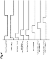
FIG. 4 is a timing chart illustrating operations of the spinning machine. -
FIG. 5 is a diagram for explaining operations of the spinning machine. -
FIG. 6 is a diagram for explaining operations of the spinning machine. -
FIG. 7 is a diagram for explaining operations of the spinning machine. -
FIG. 8(a), FIG. 8(b), and FIG. 8(c) are diagrams illustrating positions of a package and a suction mouth. - The following is a detailed explanation of a preferred embodiment of the present invention with reference to the drawings. In the explanation of the drawings, the same or corresponding elements are denoted with the same reference numerals, and an overlapping explanation thereof is omitted.
- As illustrated in
FIG. 1 , a spinning machine (textile machine) 1 includes a plurality of spinning units (winding unit) 2, a yarn joining carrier (carrier) 3, a doffing carrier (not illustrated), a first end frame 4, and asecond end frame 5. The spinningunits 2 are arranged in a line. Each of thespinning units 2 forms yarn Y and winds the yarn Y into a package P. When the package P becomes a full package in aspinning unit 2, the doffing carrier doffs the full package P, and supplies a new bobbin B to thespinning unit 2. - The first end frame 4 accommodates a collecting device collecting fiber waste, yarn waste, and the like generated in the
spinning units 2, and other components. Thesecond end frame 5 accommodates an air supply part regulating the air pressure of compressed air (air) supplied to the spinningmachine 1 and supplying air to each part of the spinningmachine 1, a drive motor to supply motive power to each part of thespinning units 2, and other components . Thesecond end frame 5 is provided with a machine control device (control part) 15, adisplay screen 16, and input keys (operating part) 17. Themachine control device 15 includes astorage part 15A and performs concentrated management and control of each part of the spinningmachine 1. Thedisplay screen 16 is capable of displaying details of settings and/or information relating to the state of thespinning units 2. The setting work for thespinning units 2 is performed by an operator's proper operation using theinput keys 17. - Each of the
spinning units 2 includes adraft device 6, an air spinning device (yarn feeder) 7, ayarn monitoring device 8, atension sensor 9, ayarn storage device 11, awaxing device 12, and a windingdevice 13, in this order from the upstream side in the traveling direction of the yarn Y. Aunit controller 10 is provided for a predetermined number ofspinning units 2, and controls operations of thespinning units 2. - The
draft device 6 drafts a sliver (fiber bundle) S. Theair spinning device 7 twists, with an air swirling flow, the fiber bundle F drafted with thedraft device 6 to form yarn Y. More specifically (illustration thereof is omitted), theair spinning device 7 includes a spinning chamber, a fiber guiding part, a swirling air flow generation nozzle, and a hollow guide shaft member. The fiber guiding part guides the fiber bundle F fed from theupstream draft device 6 into the spinning chamber. The swirling air flow generation nozzle is disposed around a path along which the fiber bundle F travels . Air is blown out of the swirling air flow generation nozzle to generate a swirling air flow in the spinning chamber. With the swirling air flow, each fiber end of a plurality of fibers forming the fiber bundle F is reversed and swirled. The hollow guide shaft member guides the yarn Y from the inside of the spinning chamber to the outside of theair spinning device 7. - The
yarn storage device 11 removes slack of the yarn Y between theair spinning device 7 and the windingdevice 13. The waxingdevice 12 provides the yarn Y with wax between theyarn storage device 11 and the windingdevice 13. - The winding
device 13 winds the yarn Y on a bobbin B to form a package P. The windingdevice 13 includes acradle arm 21, a windingdrum 22, and atraverse guide 23. Thecradle arm 21 rotatably supports the bobbin B. Thecradle arm 21 is swingably supported with asupport shaft 24 to bring the surface of the bobbin B or the surface of the package P into contact with the surface of the windingdrum 22 with proper pressure. The drive motor (not illustrated) provided in thesecond end frame 5 drives the windingdrums 22 of thespinning units 2 together. In this manner, in each of thespinning units 2, the bobbin B or the package P is rotated in a winding direction. Thetraverse guide 23 of each of thespinning units 2 is provided on a shaft (not illustrated) shared between the spinningunits 2. The drive motor of thesecond end frame 5 reciprocally drives the shaft in the rotational axis direction of the windingdrum 22, so that thetraverse guide 23 causes the yarn Y to traverse with a predetermined width with respect to the rotating bobbin B or package P. - The
yarn monitoring device 8 monitors information of the travelling yarn Y between theair spinning device 7 and theyarn storage device 11, and detects the presence or the absence of yarn defects on the basis of the monitored information. When any yarn defect is detected, theyarn monitoring device 8 transmits a yarn defect detection signal to theunit controller 10. Thetension sensor 9 measures the tension of the traveling yarn Y between theair spinning device 7 and theyarn storage device 11, and transmits a tension measurement signal to theunit controller 10. When theunit controller 10 detects an abnormality on the basis of the detection result of theyarn monitoring device 8 and/or thetension sensor 9, the yarn Y is cut in thespinning unit 2. - In each of the
spinning units 2, theair spinning device 7 is disposed above the windingdevice 13. Accordingly, the yarn Y travels from the upper side to the lower side in the height direction of thespinning unit 2. However, the traveling direction of the yarn Y is not limited to the direction described above. For example, the windingdevice 13 may be disposed above theair spinning device 7 such that the yarn Y travels from the lower side to the upper side. - When the yarn Y is cut or broken for some reason in a
spinning unit 2, theyarn joining carrier 3 performs a yarn joining operation insuch spinning unit 2. One or a plurality (for example, two to eight) ofyarn joining carriers 3 are provided in the spinningmachine 1. In the present embodiment, a plurality ofyarn joining carriers 3 are provided. Each of theyarn joining carriers 3 travels along the arrangement direction (the left-and-right direction inFIG. 1 ) of thespinning units 2. Each of theyarn joining carriers 3 travels by drive of a wheel with a travelingmotor 18 as illustrated inFIG. 1 . - As illustrated in
FIG. 2 , each of theyarn joining carriers 3 includes ayarn joining device 26, asuction pipe 27, a suction mouth (catching device) 28, ayarn guide 33, a package plate (contact device) 34, and areverse rotation device 35. As illustrated inFIG. 3 , each of theyarn joining carriers 3 includes afirst drive part 40 driving thesuction pipe 27, asecond drive part 41 driving thesuction mouth 28, athird drive part 42 driving theyarn joining device 26, afourth drive part 43 driving theyarn guide 33, afifth drive part 44 driving thepackage plate 34, and asixth drive part 45 driving thereverse rotation device 35. Themachine control device 15 controls thefirst drive part 40, thesecond drive part 41, thethird drive part 42, thefourth drive part 43, thefifth drive part 44, and thesixth drive part 45. - The
yarn joining device 26 joins the guided first yarn Y1 (seeFIG. 8 ) and the second yarn Y2 (seeFIG. 8 ) . Theyarn joining device 26 is a splicer using compressed air, a knotter mechanically joining the yarn Y, or other devices. Theyarn joining device 26 may be a piecer reversely feeding the yarn Y from the package P to theair spinning device 7 and starting a drafting operation of thedraft device 6 and a spinning operation of theair spinning device 7 to join the yarn Y. The present embodiment illustrates the case of using a splicer, as an example. Theyarn joining device 26 includes ayarn joining part 26a, asupport member 26b, arail 26c, and amotor 26d. - The
yarn joining part 26a includes a joining nozzle joining the first yarn Y1 drawn from theair spinning device 7 and the second yarn Y2 drawn from the package P, a first untwisting pipe untwisting a yarn end of the first yarn Y1, a second untwisting pipe untwisting a yarn end of the second yarn Y2, a first clamp part clamping the first yarn Y1, a second clamp part clamping the second yarn Y2, a first yarn handling lever and a first yarn presser lever regulating the first yarn Y1, and a second yarn handling lever and a second yarn presser lever regulating the second yarn Y2 (each of the elements is not illustrated). Themotor 26d serves as the drive source of a cam mechanism operating the first yarn handling lever, the second yarn handling lever, the first yarn presser lever, and the second yarn presser lever. - The
support member 26b supports theyarn joining part 26a. Thesupport member 26b is slidably attached to therail 26c. Therail 26c is fixed on the housing of theyarn joining carrier 3, and extends in a direction substantially orthogonal to the traveling direction of theyarn joining carrier 3 and the vertical direction. - In the
yarn joining device 26, theyarn joining part 26a supported with thesupport member 26b moves along therail 26c by operation of thethird drive part 42. Theyarn joining part 26a moves between a yarn joining position (seeFIG. 8 ) where theyarn joining part 26a performs a yarn joining operation and a standby position (seeFIG. 2 ) where theyarn joining part 26a performs no yarn joining operation. Thethird drive part 42 is, for example, a single acting cylinder. One end of the single acting cylinder serving as thethird drive part 42 is coupled with thesupport member 26b, and the other end of the single acting cylinder is fixed on the housing of theyarn joining carrier 3. - The
suction pipe 27 is rotatably supported with asupport shaft 31. Thesuction pipe 27 catches the first yarn Y1 from theair spinning device 7 and guides the first yarn Y1 to theyarn joining device 26. Thesuction pipe 27 is provided to be movable between a standby position P11, a first yarn catching position P12 (seeFIG. 6 ) where thesuction pipe 27 catches the first yarn Y1 from theair spinning device 7, and a first yarn guiding position P13 (seeFIG. 8 ) where thesuction pipe 27 guides the first yarn Y1 to theyarn joining device 26. Thesuction pipe 27 moves to the standby position P11, the first yarn catching position P12, and the first yarn guiding position P13 by operation of thefirst drive part 40. Thefirst drive part 40 is, for example, a motor. - The
suction mouth 28 is rotatably supported with asupport shaft 32. Thesuction mouth 28 catches the second yarn Y2 from the windingdevice 13 and guides the second yarn Y2 to theyarn joining device 26. Thesuction mouth 28 includes a catchingpart 28a catching the second yarn Y2, and asupport part 28b movably supporting the catchingpart 28a. The catchingpart 28a is provided at a distal end (distal end of the suction mouth 28) of thesupport part 28b. The catchingpart 28a is a suction port provided at the distal end of thesupport part 28b (distal end of the suction mouth 28). The suction port is provided on the catchingpart 28a such that the suction port is opposed to the surface of the package P when thesuction mouth 28 is positioned at a second yarn catching position P22. - The
suction mouth 28 is provided to be movable between a standby position P21, the second yarn catching position P22 (seeFIG. 6 ) where thesuction mouth 28 catches the second yarn Y2 from the windingdevice 13, and a second yarn guiding position P23 (seeFIG. 7 ) where thesuction mouth 28 guides the second yarn Y2 to theyarn joining device 26. Thesuction mouth 28 moves to the standby position P21, the second yarn catching position P22, and the second yarn guiding position P23 by operation of thesecond drive part 41. Thesecond drive part 41 is, for example, a motor (stepping motor) . - The
yarn guide 33 regulates the position of the yarn Y in a direction orthogonal to the traveling direction of the yarn Y. Theyarn guide 33 is positioned between theyarn joining device 26 and the package P. Theyarn guide 33 includes a regulatingplate 33a and a pair of regulatingbars 33b. One end of the regulatingplate 33a is coupled with a support shaft. In this manner, the regulatingplate 33a is provided swingably around the support shaft. - As illustrated in
FIG. 5 , the regulating bars 33b are arranged on the regulatingplate 33a. One end of each of the regulatingbars 33b is coupled with a support shaft provided on the regulatingplate 33a. In this manner, the regulating bars 33b are swingable around the support shaft by operation of a drive source (not illustrated) . Each of the regulating bars 33b swings in an approaching direction in which the regulating bars 33b approach each other and in a separating direction in which the regulating bars 33b are separated from each other. In the position where the regulating bars 33b are close to each other, the regulating bars 33b extend in parallel with each other. In this state, the yarn Y regulated with the regulatingbars 33b is positioned at substantially the center in the width direction of the package P. - The
yarn guide 33 is provided to be movable, by swing of the regulatingplate 33a, between a regulating position (seeFIG. 5 ) where the regulatingplate 33a overlaps a yarn path and a standby position (seeFIG. 2 ) where the regulatingplate 33a does not overlap the yarn path. The regulating position is a position to regulate the yarn Y to prevent the yarn Y from being caused to traverse with thetraverse guide 23. As viewed in the side view illustrated inFIG. 2 , the position of the distal end of the regulatingplate 33a moves back and forth with respect to the yarn path by swing of the regulatingplate 33a. Theyarn guide 33 moves to the regulating position and the standby position by operation of thefourth drive part 43. Thefourth drive part 43 is, for example, a cylinder. - The
package plate 34 positions the package P by pressing the package P supported with the windingdevice 13. Thepackage plate 34 is capable of braking the package P (decelerating and stopping inertial rotation of the package P) by making frictional contact with the package P separated from the windingdrum 22 in interruption of winding of the package P. The braking time for the package P, that is, the length of the time for which thepackage plate 34 is in contact with the package P can be properly set in accordance with the diameter of the package P. Thepackage plate 34 includes asupport arm 34a and acontact plate 34b. One end of thesupport arm 34a is coupled with a support shaft. Accordingly, thesupport arm 34a is able to swing around the support shaft. Thecontact plate 34b is provided on the other end of thesupport arm 34a. Thecontact plate 34b is a plate-like member including a surface to contact the package P. - The
package plate 34 is provided to be movable, by swing of thesupport arm 34a, between a standby position (origin position) P3 (seeFIG. 2 ) where thecontact plate 34b does not contact the package P and a contact position P4 (seeFIG. 5 ) where thecontact plate 34b contacts the package P. Thepackage plate 34 moves to the standby position P3 and the contact position P4 by operation of thefifth drive part 44. Thefifth drive part 44 is, for example, a stepping motor. Thefifth drive part 44 is a drive source dedicated for thepackage plate 34. For this reason, thepackage plate 34 is operable independently of the other devices . Thefifth drive part 44 is provided with a reduction pulley and a belt (not illustrated) . This structure enables prevention of loss of synchronism of thefifth drive part 44 when thepackage plate 34 contacts the package P. - The
package plate 34 is provided with adetection target member 34c. In the present embodiment, thedetection target member 34c is disposed on thesupport arm 34a of thepackage plate 34. Thedetection target member 34c is, for example, a magnet. Theyarn joining carrier 3 includes afirst detector 50 and asecond detector 52 detecting thedetection target member 34c. Each of thefirst detector 50 and thesecond detector 52 is, for example, a magnetic sensor (hall IC) . - The
first detector 50 is disposed at a position to detect thedetection target member 34c when thepackage plate 34 is positioned at the standby position P3. In the present embodiment, the standby position of thepackage plate 34 is the origin position of thepackage plate 34 detected with thefirst detector 50. Thesecond detector 52 is disposed at a position closer to the windingdevice 13 than thefirst detector 50 is. Thesecond detector 52 is disposed at a position to detect thedetection target member 34c when thepackage plate 34 moves toward the contact position P4. Each of thefirst detector 50 and thesecond detector 52 outputs a detection signal to themachine control device 15 when it detects thedetection target member 34c. - The
reverse rotation device 35 reversely rotates the package P of the windingdevice 13. Thereverse rotation device 35 includes asupport arm 35a and areverse roller 35b. One end of thesupport arm 35a is coupled with a support shaft. Accordingly, thesupport arm 35a is able to swing around the support shaft. Thereverse roller 35b is provided at the other end of thesupport arm 35a. Thereverse roller 35b is rotated in a direction opposite to the windingdrum 22 of the windingdevice 13 with a drive source (motor) that is not illustrated. - The
reverse rotation device 35 moves, by swing of thesupport arm 35a, to a standby position (seeFIG. 2 ) where thereverse roller 35b does not contact the package P and a contact position (seeFIG. 7 ) where thereverse roller 35b contacts the package P. Thereverse rotation device 35 moves to the standby position and the contact position by operation of thesixth drive part 45. Thesixth drive part 45 is, for example, a motor. - The following is an explanation of operations of the
yarn joining carrier 3 with reference toFIG. 4 .FIG. 2 andFIG. 5 toFIG. 7 are referred to with respect to movement of each of the parts of theyarn joining carrier 3. In the following explanation, actuation of each of the drive parts is controlled on the basis of a control signal transmitted from themachine control device 15. - When yarn breakage or yarn cut occurs in a
spinning unit 2, themachine control device 15 transmits, to theyarn joining carrier 3, a control signal to move theyarn joining carrier 3 to thespinning unit 2. When theyarn joining carrier 3 receives the control signal, theyarn joining carrier 3 travels to thespinning unit 2. The travelingmotor 18 stops actuation in front of thespinning unit 2, and theyarn joining carrier 3 stops traveling. In thespinning unit 2, thecradle arm 21 of the windingdevice 13 is moved in a direction away from the windingdrum 22 to separate the package P from the windingdrum 22. - Thereafter, the
yarn guide 33 and thepackage plate 34 operate at the same timing. Thefourth drive part 43 operates when or before theyarn joining carrier 3 is stopped, and moves theyarn guide 33. Theyarn guide 33 moves from the standby position to the regulating position, and is stopped at the regulating position. In this state, the regulating bars 33b of theyarn guide 33 are separated from each other. - The
fifth drive part 44 operates when or before theyarn joining carrier 3 is stopped, that is, at the same timing as start of operation of thefourth drive part 43, and moves thepackage plate 34. Thepackage plate 34 moves from the standby position P3 to the contact position P4, and is stopped at the contact position P4. Specifically, themachine control device 15 reads information indicating the contact position P4 corresponding to the lot and the diameter of the package P from thestorage part 15A. In addition, to position thepackage plate 34 at the contact position P4 indicated with the information, themachine control device 15 controls thefifth drive part 44 such that thepackage plate 34 moves by a certain distance from the standby position P3 detected with thefirst detector 50. The diameter of the package P is determined on the basis of the length (yarn length) of the yarn Y wound on the package P. - In the present embodiment, the
machine control device 15 controls the number of pulses output to the stepping motor serving as thefifth drive part 44 to move thepackage plate 34 by a certain distance from the standby position P3. Themachine control device 15 determines that thepackage plate 34 has moved to the contact position P4 when thedetection target member 34c is detected with thesecond detector 52 after thedetection target member 34c has become undetected at the standby position P3. Themachine control device 15 notifies (by display of text, turning on a lamp, and/or generation of alarm sound) the operator that an abnormality (such as contact with another object) has occurred in thepackage plate 34 when thedetection target member 34c is not detected with thesecond detector 52 even after a predetermined time has passed after thedetection target member 34c has become undetected with thefirst detector 50. - Thereafter, the
reverse rotation device 35 and thesuction mouth 28 operate at the same timing. Thesixth drive part 45 operates while thepackage plate 34 is returning to the standby position P3 or when thepackage plate 34 is stopped at the standby position P3, and moves thereverse rotation device 35. Thereverse rotation device 35 moves from the standby position to the contact position, and is stopped at the contact position. When thereverse roller 35b of thereverse rotation device 35 contacts the package P, the package P is rotated in a direction (unwinding direction) in which the second yarn Y2 is unwound. - The
second drive part 41 operates while thepackage plate 34 is returning to the standby position P3 or when thepackage plate 34 is stopped at the standby position P3, that is, at the same timing as start of operation of thereverse rotation device 35, and moves thesuction mouth 28. Thesuction mouth 28 moves from the standby position P21 to the second yarn catching position P22, and catches the second yarn Y2 at the second yarn catching position P22. - The
second drive part 41 operates when the second yarn Y2 is caught in thesuction mouth 28, and moves thesuction mouth 28. Themachine control device 15 determines whether catching of the second yarn Y2 in thesuction mouth 28 has succeeded, on the basis of the detection result of a sensor (not illustrated) provided in thesuction mouth 28. By operation of thesecond drive part 41, thesuction mouth 28 moves from the second yarn catching position P22 to the second yarn guiding position P23 to guide the second yarn Y2 to theyarn joining device 26. After thesuction mouth 28 has guided the second yarn Y2 to theyarn joining device 26, thesuction mouth 28 is stopped at the standby position P21. - When the second yarn Y2 is not caught with the
suction mouth 28, themachine control device 15 may control thefifth drive part 44 such that thepackage plate 34 is positioned at the contact position P4 in a state in which the package P is rotated with thereverse rotation device 35. - The
sixth drive part 45 operates when thesuction mouth 28 is stopped at the standby position P21, and moves thereverse rotation device 35. Thereverse rotation device 35 moves from the contact position to the standby position. Accordingly, rotation of the package P is stopped. In this state, themachine control device 15 may control thefifth drive part 44 such that thecontact plate 34b of thepackage plate 34 is positioned at the contact position P4. - The
yarn guide 33 operates the regulating bars 33b when thesuction mouth 28 is positioned at the second yarn guiding position P23. Specifically, theyarn guide 33 moves the regulating bars 33b in the direction in which the regulating bars 33b approach each other. In this manner, the second yarn Y2 caught with thesuction mouth 28 is positioned with the regulatingbars 33b. - Thereafter, the
suction pipe 27 operates. Thefirst drive part 40 operates when the second yarn Y2 is caught in thesuction mouth 28 and thesuction mouth 28 has swung to a predetermined position, and moves thesuction pipe 27. Specifically, when thesecond drive part 41 is a stepping motor, themachine control device 15 detects the position of thesuction mouth 28 on the basis of the number of pulses output to the stepping motor. Themachine control device 15 detects the position of thesuction mouth 28, and transmits a control signal to thefirst drive part 40 when thesuction mouth 28 has reached the predetermined position. - By operation of the
first drive part 40, thesuction pipe 27 moves from the standby position P11 to the first yarn catching position P12, and catches the first yarn Y1 at the first yarn catching position P12. Themachine control device 15 determines whether catching of the first yarn Y1 in thesuction pipe 27 has succeeded, on the basis of the detection result of a sensor (not illustrated) provided in thesuction pipe 27. Thefirst drive part 40 operates when the first yarn Y1 is caught in thesuction pipe 27, and moves thesuction pipe 27. Thesuction pipe 27 moves from the first yarn catching position P12 to the first yarn guiding position P13, and guides the first yarn Y1 to theyarn joining device 26. After thesuction pipe 27 has guided the first yarn Y1 to theyarn joining device 26, thesuction pipe 27 is stopped at the standby position P11. - Thereafter, the
yarn joining device 26 operates. Themachine control device 15 transmits a control signal to thethird drive part 42. Thethird drive part 42 operates at the timing at which the first yarn Y1 is caught in thesuction pipe 27, the timing at which thesuction pipe 27 starts moving to the first yarn guiding position P13, or while thesuction pipe 27 is moving to the first yarn guiding position P13, and moves theyarn joining part 26a. Theyarn joining part 26a moves from the standby position to the yarn joining position, and is stopped at the yarn joining position. Theyarn joining part 26a performs, at the yarn joining position, a yarn joining operation on the first yarn Y1 and the second yarn Y2, and releases the yarn Y after the yarn joining operation is finished. - Thereafter, the
third drive part 42 operates. Theyarn joining part 26a moves from the yarn joining position to the standby position, and is stopped at the standby position. When the first yarn Y1 and the second yarn Y2 are joined in theyarn joining part 26a, the regulating bars 33b of theyarn guide 33 move in the separating direction. In this manner, regulation of the yarn Y with theyarn guide 33 is released. Thefourth drive part 43 operates at the timing at which theyarn joining part 26a moves to the standby position, and moves theyarn guide 33. The timing at which thefourth drive part 43 operates is properly set in accordance with the timing at which the yarn joining operation is finished in theyarn joining part 26a. Theyarn guide 33 moves from the regulating position to the standby position. By the above, the yarn joining operation with theyarn joining carrier 3 is finished. When the yarn joining operation is finished, themachine control device 15 transmits to theyarn joining carrier 3, for example, a control signal to move theyarn joining carrier 3 to thenext spinning unit 2. - The following is an explanation of a method for adjusting the contact position P4 of the
package plate 34. - The
machine control device 15 sets an initial position of the contact position P4 on the basis of a preset calculation expression. Themachine control device 15 sets, for each of the lots of the packages P, the contact position P4 of thepackage plate 34 in accordance with the diameter of the package P. Specifically, themachine control device 15 changes the method for adjusting the contact position P4 (predetermined distance) between the case where the diameter of the package P is smaller than a predetermined value and the case where the diameter of the package P is equal to or larger than the predetermined value. In the present embodiment, themachine control device 15 adjusts the contact position P4 such that the predetermined distance is fixed when the diameter of the package P is smaller than the predetermined value, and adjusts the contact position P4 such that the predetermined distance decreases linearly or in a stepped manner in accordance with increase in diameter of the package P when the diameter of the package P is equal to or larger than the predetermined value. - The
machine control device 15 stores, for each of the lots, information indicating the contact position P4 set as described above in thestorage part 15A. Thestorage part 15A stores therein, for each of the lots, the contact position P4 in association with the diameter of the package P. Thestorage part 15A stores therein the movement distance (predetermined distance) from the standby position P3 as information indicating the contact position P4. Themachine control device 15 reads the contact position P4 associated with the package P from thestorage part 15A, and outputs the pulses to thefifth drive part 44 in a number corresponding to the movement distance such that thepackage plate 34 is positioned at the contact position P4. - When the
suction mouth 28 has failed in catching of the second yarn Y2 at the contact position P4, themachine control device 15 adjusts the contact position P4. In the present embodiment, themachine control device 15 adjusts the contact position P4 when thesuction mouth 28 has failed in catching of the second yarn Y2 a predetermined number of times or more, or when the number of failures in catching of the second yarn Y2 in a predetermined period of time is larger than the number of successes. The number of times and/or the predetermined period of time can be set by an operator's operation of theinput keys 17. The operator inputs, with theinput keys 17, the number of times and/or the predetermined period of time (information relating to failure in catching of the second yarn Y2 with thesuction mouth 28 for one contact position P4). The following explanation illustrates the case where themachine control device 15 adjusts the contact position P4 when thesuction mouth 28 has failed in catching of the second yarn Y2 a predetermined number of times or more. - When the
suction mouth 28 has failed in catching of the second yarn Y2 a predetermined number of times or more at one contact position P4 and thesuction mouth 28 performs catching of the second yarn Y2 next, themachine control device 15 moves thepackage plate 34 by a distance longer than the predetermined distance by which thepackage plate 34 has been moved from the standby position P3 to position thepackage plate 34 at the previous contactposition P4. Specifically, themachine control device 15 increases the number of pulses (increases the movement distance) output to thefifth drive part 44. For example, as illustrated inFIG. 8(a) , the distance between the catchingpart 28a of thesuction mouth 28 and the package P is the distance D, with the initial contact position P4 where thesuction mouth 28 has failed in catching of the second yarn Y2 a predetermined number of times or more. Themachine control device 15 increases the number of pulses output to thefifth drive part 44 to change the contact position P4. In this manner, as illustrated inFIG. 8(b) , the distance D1 between the package P positioned with thepackage plate 34 positioned at the changed contact position P4 and the catchingpart 28a of thesuction mouth 28 is longer than the distance D (D < D1). - When the
suction mouth 28 has failed in catching of the second yarn Y2 a predetermined number of times or more at the changed contact position P4, themachine control device 15 moves thepackage plate 34 by a distance shorter than the predetermined distance by which thepackage plate 34 has been moved from the standby position P3 to position thepackage plate 34 at such contact position P4. Specifically, themachine control device 15 decreases the number of pulses (for example, decreases few pulses) output to thefifth drive part 44. Themachine control device 15 shortens the distance by a certain distance (decreases the number of pulses by a fixed number of pulses (for example, two to three pulses)) when the diameter of the package P is smaller than the predetermined value, and shortens the predetermined distance linearly or in a stepped manner (decreases the number of pulses linearly or in a stepped manner) when the diameter of the package P is equal to or larger than the predetermined value. In this manner, as illustrated inFIG. 8(c) , the distance D2 between the package P positioned with thepackage plate 34 positioned at the changed contact position P4 and the catchingpart 28a of thesuction mouth 28 is shorter than the distance D1 (D1 < D2). Themachine control device 15 shortens the predetermined distance until the number of failures in catching of the second yarn Y2 with thesuction mouth 28 becomes smaller than the predetermined number of times, to adjust the contact position P4. When the number of failures in catching of the second yarn Y2 with thesuction mouth 28 becomes smaller than the predetermined number of times, themachine control device 15 stores, in thestorage part 15A, the contact position P4 of thepackage plate 34 in this state in association with the lot. - As described above, in the spinning
machine 1 according to the present embodiment, themachine control device 15 adjusts the contact position P4 of thepackage plate 34. The position of the package P separated from the windingdrum 22 is adjusted by contact with thepackage plate 34. For this reason, in the spinningmachine 1, the contact position P4 is adjusted in accordance with the characteristics of the package P, so that the distance between the catchingpart 28a of thesuction mouth 28 and the package P can be adjusted to an optimum distance to catch the second yarn Y2. Accordingly, the spinningmachine 1 enables improvement in accuracy of catching the second yarn Y2 with thesuction mouth 28. - The spinning
machine 1 according to the present embodiment includes thestorage part 15A storing therein the contact position P4 of thepackage plate 34 for each of the lots of the packages P. Themachine control device 15 controls thefifth drive part 44 on the basis of the contact position P4 stored in thestorage part 15A. This structure enables adjustment of the distance between the catchingpart 28a of thesuction mouth 28 and the package P to an optimum distance for each of the lots. - In the spinning
machine 1 according to the present embodiment, when thesuction mouth 28 has failed in catching of the second yarn Y2, themachine control device 15 adjusts the contact position P4 such that the distance is set longer than the predetermined distance to position thesuction mouth 28 at the contact position P4 where catching has failed. This structure enables setting of the contact position P4 to a position other than the contact position P4 where catching of the second yarn Y2 has failed. Thus, this structure enables the spinningmachine 1 to adjust the distance between the catchingpart 28a of thesuction mouth 28 and the package P to an optimum distance. - In the spinning
machine 1 according to the present embodiment, themachine control device 15 adjusts the contact position P4 such that the predetermined distance is increased when thesuction mouth 28 has failed in catching of the second yarn Y2, and adjusts the contact position P4 such that the predetermined distance is shortened when thesuction mouth 28 has failed in catching of the second yarn Y2 at the previous contact position P4. When the distance between the catchingpart 28a of thesuction mouth 28 and the package P is too short, disorder may occur on the surface (surface layer) of the package P. For this reason, in the spinningmachine 1, the predetermined distance is increased first to increase the distance between the catchingpart 28a of thesuction mouth 28 and the package P, and thereafter the predetermined distance is shortened to shorten the distance between the catchingpart 28a of thesuction mouth 28 and the package P. With this structure, the spinningmachine 1 enables adjustment of the distance between the catchingpart 28a of thesuction mouth 28 and the package P to an optimum distance while avoiding occurrence of disorder on the surface of the package P. - In the spinning
machine 1 according to the present embodiment, themachine control device 15 controls thefifth drive part 44 such that the predetermined distance is shortened in accordance with increase in diameter of the package P. When an input is made with theinput keys 17, themachine control device 15 adjusts the contact position P4 such that the predetermined distance is increased even when the diameter of the package P increases. Generally, in the spinningmachine 1, the movement distance of thepackage plate 34 is shortened when the diameter of the package P increases. In the spinningmachine 1, when an operation by an operator is performed, an operation different from usual is performed to adjust the contact position P4 of thepackage plate 34. With this structure, the spinningmachine 1 enables proper adjustment of the contact position P4. - In the spinning
machine 1 according to the present embodiment, themachine control device 15 controls thefifth drive part 44 such that thepackage plate 34 is moved from the origin position by the predetermined distance after the origin position of thepackage plate 34 is detected with thefirst detector 50. This structure enables movement of thepackage plate 34 to the contact position P4 with high accuracy. - In the spinning
machine 1 according to the present embodiment, themachine control device 15 causes thepackage plate 34 to stand by at the origin position detected with thefirst detector 50. In this structure, the standby position P3 of thepackage plate 34 is the origin position. Thus, it suffices that thefifth drive part 44 moves thepackage plate 34 between the standby position P3 (origin position) and the contact position P4. This structure enables simplification of control in the spinningmachine 1. - In the spinning
machine 1 according to the present embodiment, thefifth drive part 44 is a stepping motor. Themachine control device 15 adjusts the predetermined distance of thepackage plate 34 with the number of pulses output to thefifth drive part 44. This structure enables movement of thepackage plate 34 with high accuracy. - In the spinning
machine 1 according to the present embodiment, theyarn joining carrier 3 includes thesecond detector 52 detecting movement of thepackage plate 34 from the standby position P3 to the contact position P4. When thepackage plate 34 is not detected with thesecond detector 52, there is the possibility that some failure (such as contact with another object and malfunction) has occurred in thepackage plate 34. This structure enables the spinningmachine 1 to notify the operator that, for example, some failure has occurred in thepackage plate 34, and promptly perform recovery from the failure . - In the spinning
machine 1 according to the present embodiment, thepackage plate 34 is provided with thedetection target member 34c detectable with thefirst detector 50 and thesecond detector 52. Thesecond detector 52 is disposed at a position closer to the windingdevice 13 than thefirst detector 50 is. Thefirst detector 50 may detect that thepackage plate 34 is positioned at the standby position P3 by detecting thedetection target member 34c, and thesecond detector 52 may detect movement of thepackage plate 34 by detecting thedetection target member 34c. This structure enables detection of the state in which thepackage plate 34 is positioned at the origin position and movement of thepackage plate 34, with a simple structure. - In the spinning
machine 1 according to the present embodiment, themachine control device 15 adjusts the contact position P4 on the basis of the diameter of the package P. This structure enables adjustment of the distance between the catchingpart 28a of thesuction mouth 28 and the package P at the time when the second yarn Y2 of the package P is caught with thesuction mouth 28 to an optimum distance, in accordance with the diameter of the package P. - In the spinning
machine 1 according to the present embodiment, themachine control device 15 performs control to shorten the predetermined distance by a certain distance when the diameter of the package P is smaller than the predetermined value, and shorten the predetermined distance linearly or in a stepped manner when the diameter of the package P is equal to or larger than the predetermined value. When the diameter of the package P is small, the package P has a large curvature. In this case, when the predetermined distance is shortened linearly or in a stepped manner in accordance with the diameter of the package P, the distance between the package P and thesuction mouth 28 may become too long. This may impede good catching of the second yarn Y2 in thesuction mouth 28. For this reason, control is performed as described above in accordance with the diameter of the package P. This structure enables adjustment of the distance between the catchingpart 28a of thesuction mouth 28 and the package P to an optimum distance. - An embodiment of the present invention has been described above. The present invention is, however, not always limited to the embodiment described above. Various modifications are possible within the range not departing from the gist of the invention.
- The embodiment described above illustrates, as an example of a textile machine, the spinning
machine 1 including a plurality of spinningunits 2. However, the textile machine may be an automatic winder including a plurality of winding units. In this case, the yarn feeder is a support part supporting a bobbin or a package. - The embodiment described above illustrates, as an example, an aspect in which the
machine control device 15 adjusts the contact position P4 of thepackage plate 34. The spinningmachine 1 may be switchable between a mode in which the contact position P4 is automatically adjusted and a mode in which the contact position P4 is not automatically adjusted. - The embodiment described above illustrates, as an example, an aspect in which the contact position P4 of the
package plate 34 is automatically adjusted in themachine control device 15. However, adjustment of the contact position P4 with themachine control device 15 may be performed on the basis of an operator's operation. In this case, the operator inputs information to adjust the contact position P4 with theinput keys 17. Specifically, for example, the operator inputs information relating to the movement distance (the numerical value indicating the movement distance or the number of pulses) of thepackage plate 34. Themachine control device 15 adjusts the contact position P4 on the basis of the input movement distance. When a plurality ofyarn joining carriers 3 are provided, themachine control device 15 may adjust the contact positions P4 of therespective package plates 34 of theyarn joining carriers 3 together. As another example, themachine control device 15 may adjust the contact position P4 of thepackage plate 34 of each of theyarn joining carriers 3 separately. - The embodiment described above illustrates, as an example, an aspect in which, in adjustment of the contact position P4 of the
package plate 34, the movement distance of thepackage plate 34 is increased first, and thereafter the movement distance of thepackage plate 34 is shortened. However, the movement distance of thepackage plate 34 may be shortened first, and thereafter the movement distance of thepackage plate 34 may be increased gradually. - The embodiment described above illustrates, as an example, an aspect in which the method for adjusting the contact position P4 (predetermined distance) is changed between the case where the diameter of the package P is smaller than the predetermined value and the case where the diameter of the package P is equal to or larger than the predetermined value, when the contact position P4 of the
package plate 34 is set in accordance with the diameter of the package P. The method for adjusting the contact position P4 may be used only when the contact position P4 is adjusted in the case where thesuction mouth 28 has failed in catching of the second yarn Y2. - The embodiment described above illustrates, as an example, an aspect in which the
machine control device 15 performs control to shorten the predetermined distance by a certain distance when the diameter of the package P is smaller than the predetermined value, and shorten the predetermined distance linearly or in a stepped manner when the diameter of the package P is equal to or larger than the predetermined value. However, the predetermined distance may be increased linearly or in a stepped manner when the diameter of the package P is smaller than the predetermined value. It suffices that themachine control device 15 changes the method for adjusting the contact position P4 (predetermined distance) between the case where the diameter of the package P is smaller than the predetermined value and the case where the diameter of the package P is equal to or larger than the predetermined value. - The embodiment described above illustrates, as an example, an aspect in which the
package plate 34 is provided with thedetection target member 34c, and thedetection target member 34c is detected with thefirst detector 50 so as to detect the standby position (origin position) P3 of thepackage plate 34. However, the standby position P3 of thepackage plate 34 may be detected by another method. - The embodiment described above illustrates, as an example, an aspect in which the
storage part 15A stores therein the contact position P4 (movement distance) according to the diameter of the package P for each of the lots, and themachine control device 15 controls thefifth drive part 44 on the basis of the contact position P4 stored in thestorage part 15A. However, thestorage part 15A may store no contact position P4 therein for each of the lots. Thestorage part 15A may store therein information relating to failures in catching of the second yarn Y2 with thesuction mouth 28. In this case, themachine control device 15 adjusts the contact position P4 on the basis of the information stored in thestorage part 15A. Specifically, themachine control device 15 adjusts the contact position P4 to a contact position P4 other than the contact position P4 where catching of the second yarn Y2 has failed, on the basis of the information. Because the contact position P4 is adjusted on the basis of the information (such as the failure rate and the number of failures) relating to failures of catching, this structure enables proper setting of the contact position P4 enabling success in catching of the second yarn Y2. With this structure, the spinningmachine 1 is able to adjust the distance between the catchingpart 28a of thesuction mouth 28 and the package P to an optimum distance. - The embodiment described above illustrates, as an example, an aspect in which the
yarn joining device 26, thesuction pipe 27, thesuction mouth 28, theyarn guide 33, and thereverse rotation device 35 are driven with thethird drive part 42, thefirst drive part 40, thesecond drive part 41, thefourth drive part 43, and thesixth drive part 45, respectively. However, one drive part may drive theyarn joining device 26, thesuction pipe 27, thesuction mouth 28, theyarn guide 33, and thereverse rotation device 35. As another example, one drive part may drive at least two of theyarn joining device 26, thesuction pipe 27, thesuction mouth 28, theyarn guide 33, and thereverse rotation device 35. - The embodiment described above illustrates, as an example, an aspect in which the
fifth drive motor 44 is a stepping motor. However, thefifth drive part 44 may be a servo motor. - The embodiment described above illustrates, as an example, an aspect in which the first to the
sixth drive parts 40 to 45 are motors or cylinders. However, the first to thesixth drive parts 40 to 45 may be drive sources other than the examples described above. - The embodiment described above illustrates, as an example, an aspect in which the
machine control device 15 controls operations of theyarn joining carrier 3. However, theyarn joining carrier 3 may be controlled with a carrier controller (control part) provided in theyarn joining carrier 3. In this case, theunit controller 10 may transmit a signal indicating yarn breakage or yarn cut to the carrier controller of theyarn joining carrier 3, or the signal may be transmitted from theunit controller 10 to the carrier controller through themachine control device 15. As another example, theunit controller 10 may control operations of theyarn joining carrier 3. - The embodiment described above illustrates, as an example, an aspect in which the
package plate 34 includes thesupport arm 34a and thecontact plate 34b. However, the structure of thepackage plate 34 is not limited to the example. The package plate may have any structure as long as it has the structure of contacting the package P by movement from the standby position P3 to the contact position P4. - The embodiment described above illustrates, as an example, an aspect in which the
spinning machine 1 includes theyarn joining carrier 3 and the doffing carrier. However, the yarn joining carrier may have a doffing function. - In addition to the embodiment described above, the
air spinning device 7 may further include a needle provided to be retained with the fiber guiding part and project to the inside of the spinning chamber so as to prevent twist of the fiber bundle from being transmitted to the upstream side of the air spinning device. As another example, the air spinning device may prevent twist of the fiber bundle from being transmitted to the upstream side of the air spinning device with a downstream end portion of the fiber guiding part instead of such a needle. As another example, instead of the structures described above, the air spinning device may include a pair of air blowing nozzles twisting the fiber bundle in mutually opposite directions. The spinning machine may be an open-end spinning machine. - In the embodiment described above, the
yarn storage device 11 has a function of drawing the yarn Y from theair spinning device 7 in thespinning units 2. However, the yarn Y may be drawn out of theair spinning device 7 with a delivery roller and a nip roller. In this case, theyarn storage device 11 may be omitted. As another example, in this case, a slack tube absorbing slack of the yarn Y by a suction air flow or a mechanical compensator may be provided instead of theyarn storage device 11. - In the embodiment described above, the
traverse guide 23 is driven by motive power from the second end frame 5 (that is, in common for a plurality of the spinning units 2) . However, the devices (such as the draft device and the winding device) of each of thespinning units 2 may be driven independently. - The
suction pipe 27 may include a nozzle to twist the yarn end of the first yarn Y1. - In the traveling direction of the yarn Y, the
tension sensor 9 may be disposed on the upstream side of theyarn monitoring device 8. Theunit controller 10 may be provided for each of thespinning units 2. In thespinning units 2, theyarn monitoring device 8, thetension sensor 9, and thewaxing device 12 may be omitted. - The embodiment described above illustrates, as an example, an aspect of winding the cheese-shaped package P as illustrated in
FIG. 1 . However, a conical package may be wound. - 1... SPINNING MACHINE (TEXTILE MACHINE), 2... SPINNING UNIT (WINDING UNIT), 3... YARN JOINING CARRIER, 7... AIR SPINNING DEVICE (YARN FEEDER), 13... WINDING DEVICE, 15... MACHINE CONTROL DEVICE (CONTROL PART), 28... SUCTION MOUTH (CATCHING DEVICE), 34... PACKAGE PLATE (CONTACT DEVICE), 44... FIFTH DRIVE PART (DRIVE PART), 50...FIRST DETECTOR, 52...SECOND DETECTOR, P... PACKAGE, P3... STANDBY POSITION (STANDBY POSITION) P4... CONTACT POSITION, Y... YARN, Y2... SECOND YARN.
Claims (17)
- A textile machine (1) comprising:a plurality of winding units (2), each of which includinga yarn feeder (7) configured to feed yarn (Y), anda winding device (13) configured to wind the yarn (Y) fed from the yarn feeder (7) to form a package (P);a carrier (3) includinga contact device (34) configured to be movable between a contact position (P4) where the contact device (34) contacts the package (P) and a standby position (P3) where the contact device (34) is separated from the package (P),a drive part (44) configured to move the contact device (34) between the contact position (P4) and the standby position (P3),a catching device (28) configured to catch the yarn (Y2) from the package (P), anda first detector (50) configured to detect an origin position (P3) of the contact device (34) ; anda control part (15) configured to adjust the contact position (P4) and control the drive part (44) to move the contact device (34) by a predetermined distance from the origin position (P3) detected with the first detector (50) such that the contact device (34) is positioned at the adjusted contact position (P4).
- The textile machine (1) according to claim 1, further comprising:a plurality of the carriers (3); andan operating part (17) configured to receive an input relating to an operation of the contact device (34), whereinthe control part (15) adjusts the contact position (P4) of the contact device (34) of each of the carriers (3) on the basis of details input in the operating part (17).
- The textile machine (1) according to claim 2, wherein
the operating part (17) receives an input of information relating to the predetermined distance of the contact device (34), and
the control part (15) adjusts the contact position (P4) on the basis of the information relating to the predetermined distance. - The textile machine (1) according to claim 2 or 3, wherein
the operating part (15) receives an input of information relating to failures in catching of the yarn (Y2) with the catching device (28), and
the control part (15) adjusts the contact position (P4) on the basis of the information relating to failures in catching of the yarn (Y2) . - The textile machine (1) according to any one of claims 1 to 4, comprising a storage part (15A) configured to store therein the contact position (P4) of the contact device (34) for each of lots of the packages (P), wherein
the control part (15) controls the drive part (44) on the basis of the contact position (P4) stored in the storage part (15A). - The textile machine (1) according to any one of claims 1 to 5, comprising a storage part (15A) configured to store therein the contact position (P4) of the contact device (34), wherein
the storage part (15A) stores therein information relating to failures in catching of the yarn (Y2) with the catching device (28), and
the control part (15) adjusts the contact position (P4) on the basis of the information stored in the storage part (15A). - The textile machine (1) according to any one of claims 1 to 6, wherein
when the catching device (28) has failed in catching of the yarn (Y2), the control part (15) adjusts the contact position (P4) by changing a distance to be shorter or longer than the predetermined distance which has been used to position the contact device (34) at the contact position (P4) where catching has failed. - The textile machine (1) according to claim 7, wherein
the control part (15) adjusts the contact position (P4) such that the distance is set longer than the predetermined distance which has been used to position the contact device (34) at the contact position (P4) where catching of the yarn (Y2) has failed, when the catching device (28) has failed in catching of the yarn (Y2), and adjusts the contact position (P4) such that the distance is set shorter than the predetermined distance which has been used to position the contact device (34) at the contact position (P4), when the catching device (28) has failed in catching of the yarn (Y2) at the contact position (P4) . - The textile machine (1) according to any one of claims 2 to 4, wherein
the control part (15) controls the drive part (44) such that the predetermined distance is shortened in accordance with increase in a diameter of the package (P), and
when an input is made with the operating part (17), the control part (15) adjusts the contact position (P4) such that the predetermined distance is increased even when the diameter of the package (P) increases. - The textile machine (1) according to any one of claims 1 to 9, wherein the control part (15) controls the drive part (44) such that the contact device (34) is moved from the origin position (P3) by the predetermined distance after the origin position (P3) of the contact device (34) is detected with the first detector (50).
- The textile machine (1) according to any one of claims 1 to 10, wherein the control part (15) causes the contact device (34) to stand by at the origin position (P3) detected with the first detector (50) .
- The textile machine (1) according to any one of claims 1 to 11, wherein
the drive part (44) is a stepping motor, and
the control part (15) adjusts the predetermined distance of the contact device (34) with a number of pulses output to the drive part (44) . - The textile machine (1) according to any one of claims 1 to 12, wherein the carrier (3) includes a second detector (52) configured to detect that the contact device (34) has moved from the standby position (P3) to the contact position (P4).
- The textile machine (1) according to claim 13, wherein
the contact device (34) includes a detection target member (34c) detectable with the first detector (50) and the second detector (52),
the second detector (52) is disposed at a position closer to the winding device (13) than the first detector (50),
the first detector (50) detects that the contact device (34) is positioned at the origin position (P3) by detecting the detection target member (34c), and
the second detector (52) detects movement of the contact device (34) by detecting the detection target member (34c). - The textile machine (1) according to any one of claims 1 to 14, wherein the control part (15) adjusts the contact position (P4) on the basis of a diameter of the package (P).
- The textile machine (1) according to claim 15, wherein the control part (15) changes a method for adjusting the contact position (P4) between a case where the diameter of the package (P) is smaller than a predetermined value and a case where the diameter of the package (P) is equal to or larger than the predetermined value.
- The textile machine (1) according to claim 16, wherein the control part (15) adjusts the contact position (P4) such that the predetermined distance is fixed when the diameter of the package (P) is smaller than the predetermined value, and adjusts the contact position (P4) such that the predetermined distance decreases linearly or in a stepped manner in accordance with increase in the diameter of the package (P) when the diameter of the package (P) is equal to or larger than the predetermined value.
Applications Claiming Priority (2)
| Application Number | Priority Date | Filing Date | Title |
|---|---|---|---|
| JP2016187245A JP2018052638A (en) | 2016-09-26 | 2016-09-26 | Textile machine |
| PCT/JP2017/034738 WO2018056462A1 (en) | 2016-09-26 | 2017-09-26 | Textile machine |
Publications (2)
| Publication Number | Publication Date |
|---|---|
| EP3517471A1 true EP3517471A1 (en) | 2019-07-31 |
| EP3517471A4 EP3517471A4 (en) | 2020-04-22 |
Family
ID=61690474
Family Applications (1)
| Application Number | Title | Priority Date | Filing Date |
|---|---|---|---|
| EP17853229.7A Withdrawn EP3517471A4 (en) | 2016-09-26 | 2017-09-26 | Textile machine |
Country Status (4)
| Country | Link |
|---|---|
| EP (1) | EP3517471A4 (en) |
| JP (1) | JP2018052638A (en) |
| CN (1) | CN109715540B (en) |
| WO (2) | WO2018056462A1 (en) |
Families Citing this family (1)
| Publication number | Priority date | Publication date | Assignee | Title |
|---|---|---|---|---|
| CN111379055B (en) * | 2020-04-10 | 2024-12-17 | 无锡米德兰机电科技有限公司 | Automatic twisting machine for spinning |
Family Cites Families (13)
| Publication number | Priority date | Publication date | Assignee | Title |
|---|---|---|---|---|
| JPS6047937B2 (en) * | 1980-10-17 | 1985-10-24 | 村田機械株式会社 | Spinning device with yarn splicing trolley |
| JPH11256435A (en) * | 1998-03-13 | 1999-09-21 | Murata Mach Ltd | Single spindle driving type multiple twister |
| JP2001139230A (en) * | 1999-11-17 | 2001-05-22 | Murata Mach Ltd | Positioning device for package |
| JP2010189083A (en) * | 2009-02-16 | 2010-09-02 | Murata Machinery Ltd | Fiber machine |
| JP2012086923A (en) * | 2010-10-18 | 2012-05-10 | Murata Machinery Ltd | Doffer and yarn winding machine including the same |
| JP2013067483A (en) * | 2011-09-21 | 2013-04-18 | Murata Machinery Ltd | Spinning machine |
| JP2013067484A (en) * | 2011-09-21 | 2013-04-18 | Murata Machinery Ltd | Spinning machine |
| JP2013252948A (en) * | 2012-06-07 | 2013-12-19 | Murata Machinery Ltd | Textile machine |
| JP2013253358A (en) * | 2012-06-08 | 2013-12-19 | Murata Mach Ltd | Spinning machine |
| JP2015151215A (en) * | 2014-02-12 | 2015-08-24 | 村田機械株式会社 | Bobbin setting device and yarn winder |
| JP2015199559A (en) * | 2014-04-04 | 2015-11-12 | 村田機械株式会社 | Working table truck, and yarn winder having the table truck |
| JP2016011176A (en) * | 2014-06-27 | 2016-01-21 | 村田機械株式会社 | Yarn winder |
| DE102014012730A1 (en) * | 2014-08-26 | 2016-03-03 | Saurer Germany Gmbh & Co. Kg | Method for operating a workstation of a textile machine producing textile cheeses or associated workstation |
-
2016
- 2016-09-26 JP JP2016187245A patent/JP2018052638A/en active Pending
-
2017
- 2017-09-26 EP EP17853229.7A patent/EP3517471A4/en not_active Withdrawn
- 2017-09-26 WO PCT/JP2017/034738 patent/WO2018056462A1/en not_active Ceased
- 2017-09-26 WO PCT/JP2017/034790 patent/WO2018056468A1/en not_active Ceased
- 2017-09-26 CN CN201780057275.0A patent/CN109715540B/en active Active
Also Published As
| Publication number | Publication date |
|---|---|
| CN109715540B (en) | 2021-01-15 |
| JP2018052638A (en) | 2018-04-05 |
| WO2018056468A1 (en) | 2018-03-29 |
| CN109715540A (en) | 2019-05-03 |
| WO2018056462A1 (en) | 2018-03-29 |
| EP3517471A4 (en) | 2020-04-22 |
Similar Documents
| Publication | Publication Date | Title |
|---|---|---|
| JP6080153B2 (en) | Spinning machine and method for interrupting the production of yarn in a spinning machine | |
| EP2727870B1 (en) | Yarn winding machine and yarn winding method | |
| EP2573235B1 (en) | Spinning machine | |
| CN106567170B (en) | Textile machine and control device | |
| EP3025995B1 (en) | Yarn winding machine | |
| EP3524556A1 (en) | Air spinning machine and air spinning method | |
| EP2573231B1 (en) | Spinning machine | |
| JP2014125714A (en) | Spinning machine | |
| EP3040458B1 (en) | Core yarn supplying device, spinning machine, and method of supplying core yarn | |
| CN108286093B (en) | Spinning machine | |
| JP7463063B2 (en) | Method or device for influencing the winding state of a ring spinning cop | |
| EP3095742A1 (en) | Yarn winding machine | |
| EP3517663A1 (en) | Spinning machine | |
| JP2020193085A (en) | Thread winder | |
| CN109715540B (en) | Textile machine and method for operating the same | |
| CN113249835B (en) | Spinning machine and spinning method | |
| JP2019104596A (en) | Yarn winding machine and yarn winding method | |
| EP3730436A1 (en) | Yarn winding machine and yarn threading method | |
| JP2020079155A (en) | Yarn winder | |
| CN111793863B (en) | Spinning method and spinning machine | |
| JP2018052639A (en) | Textile machine | |
| JP2017089090A (en) | Method for preparing a workstation for resuming a spinning process on an air jet spinning machine and an air jet spinning machine for carrying out the method | |
| JP2025003098A (en) | Core yarn supplying device, air spinning machine, core yarn spinning method and package | |
| JP2024007744A (en) | Spinning machine, package forming method and package | |
| JP2022130239A (en) | spinning machine |
Legal Events
| Date | Code | Title | Description |
|---|---|---|---|
| PUAI | Public reference made under article 153(3) epc to a published international application that has entered the european phase |
Free format text: ORIGINAL CODE: 0009012 |
|
| 17P | Request for examination filed |
Effective date: 20190417 |
|
| AK | Designated contracting states |
Kind code of ref document: A1 Designated state(s): AL AT BE BG CH CY CZ DE DK EE ES FI FR GB GR HR HU IE IS IT LI LT LU LV MC MK MT NL NO PL PT RO RS SE SI SK SM TR |
|
| AX | Request for extension of the european patent |
Extension state: BA ME |
|
| DAV | Request for validation of the european patent (deleted) | ||
| DAX | Request for extension of the european patent (deleted) | ||
| A4 | Supplementary search report drawn up and despatched |
Effective date: 20200324 |
|
| RIC1 | Information provided on ipc code assigned before grant |
Ipc: B65H 63/036 20060101ALI20200318BHEP Ipc: B65H 67/08 20060101AFI20200318BHEP Ipc: D01H 15/00 20060101ALI20200318BHEP |
|
| GRAP | Despatch of communication of intention to grant a patent |
Free format text: ORIGINAL CODE: EPIDOSNIGR1 |
|
| RIC1 | Information provided on ipc code assigned before grant |
Ipc: D01H 15/00 20060101ALI20201117BHEP Ipc: B65H 63/036 20060101ALI20201117BHEP Ipc: B65H 67/08 20060101AFI20201117BHEP |
|
| INTG | Intention to grant announced |
Effective date: 20201208 |
|
| STAA | Information on the status of an ep patent application or granted ep patent |
Free format text: STATUS: THE APPLICATION HAS BEEN WITHDRAWN |
|
| 18W | Application withdrawn |
Effective date: 20210104 |