EP3517462A1 - Conveying device - Google Patents
Conveying device Download PDFInfo
- Publication number
- EP3517462A1 EP3517462A1 EP16916830.9A EP16916830A EP3517462A1 EP 3517462 A1 EP3517462 A1 EP 3517462A1 EP 16916830 A EP16916830 A EP 16916830A EP 3517462 A1 EP3517462 A1 EP 3517462A1
- Authority
- EP
- European Patent Office
- Prior art keywords
- guide rail
- conveying device
- furnace
- guide rails
- disposed
- Prior art date
- Legal status (The legal status is an assumption and is not a legal conclusion. Google has not performed a legal analysis and makes no representation as to the accuracy of the status listed.)
- Granted
Links
Images


Classifications
-
- B—PERFORMING OPERATIONS; TRANSPORTING
- B65—CONVEYING; PACKING; STORING; HANDLING THIN OR FILAMENTARY MATERIAL
- B65G—TRANSPORT OR STORAGE DEVICES, e.g. CONVEYORS FOR LOADING OR TIPPING, SHOP CONVEYOR SYSTEMS OR PNEUMATIC TUBE CONVEYORS
- B65G47/00—Article or material-handling devices associated with conveyors; Methods employing such devices
- B65G47/74—Feeding, transfer, or discharging devices of particular kinds or types
- B65G47/82—Rotary or reciprocating members for direct action on articles or materials, e.g. pushers, rakes, shovels
-
- B—PERFORMING OPERATIONS; TRANSPORTING
- B65—CONVEYING; PACKING; STORING; HANDLING THIN OR FILAMENTARY MATERIAL
- B65G—TRANSPORT OR STORAGE DEVICES, e.g. CONVEYORS FOR LOADING OR TIPPING, SHOP CONVEYOR SYSTEMS OR PNEUMATIC TUBE CONVEYORS
- B65G25/00—Conveyors comprising a cyclically-moving, e.g. reciprocating, carrier or impeller which is disengaged from the load during the return part of its movement
- B65G25/04—Conveyors comprising a cyclically-moving, e.g. reciprocating, carrier or impeller which is disengaged from the load during the return part of its movement the carrier or impeller having identical forward and return paths of movement, e.g. reciprocating conveyors
- B65G25/06—Conveyors comprising a cyclically-moving, e.g. reciprocating, carrier or impeller which is disengaged from the load during the return part of its movement the carrier or impeller having identical forward and return paths of movement, e.g. reciprocating conveyors having carriers, e.g. belts
-
- B—PERFORMING OPERATIONS; TRANSPORTING
- B65—CONVEYING; PACKING; STORING; HANDLING THIN OR FILAMENTARY MATERIAL
- B65G—TRANSPORT OR STORAGE DEVICES, e.g. CONVEYORS FOR LOADING OR TIPPING, SHOP CONVEYOR SYSTEMS OR PNEUMATIC TUBE CONVEYORS
- B65G25/00—Conveyors comprising a cyclically-moving, e.g. reciprocating, carrier or impeller which is disengaged from the load during the return part of its movement
- B65G25/04—Conveyors comprising a cyclically-moving, e.g. reciprocating, carrier or impeller which is disengaged from the load during the return part of its movement the carrier or impeller having identical forward and return paths of movement, e.g. reciprocating conveyors
- B65G25/08—Conveyors comprising a cyclically-moving, e.g. reciprocating, carrier or impeller which is disengaged from the load during the return part of its movement the carrier or impeller having identical forward and return paths of movement, e.g. reciprocating conveyors having impellers, e.g. pushers
-
- F—MECHANICAL ENGINEERING; LIGHTING; HEATING; WEAPONS; BLASTING
- F26—DRYING
- F26B—DRYING SOLID MATERIALS OR OBJECTS BY REMOVING LIQUID THEREFROM
- F26B25/00—Details of general application not covered by group F26B21/00 or F26B23/00
- F26B25/001—Handling, e.g. loading or unloading arrangements
- F26B25/003—Handling, e.g. loading or unloading arrangements for articles
-
- F—MECHANICAL ENGINEERING; LIGHTING; HEATING; WEAPONS; BLASTING
- F26—DRYING
- F26B—DRYING SOLID MATERIALS OR OBJECTS BY REMOVING LIQUID THEREFROM
- F26B5/00—Drying solid materials or objects by processes not involving the application of heat
- F26B5/04—Drying solid materials or objects by processes not involving the application of heat by evaporation or sublimation of moisture under reduced pressure, e.g. in a vacuum
- F26B5/06—Drying solid materials or objects by processes not involving the application of heat by evaporation or sublimation of moisture under reduced pressure, e.g. in a vacuum the process involving freezing
-
- B—PERFORMING OPERATIONS; TRANSPORTING
- B65—CONVEYING; PACKING; STORING; HANDLING THIN OR FILAMENTARY MATERIAL
- B65G—TRANSPORT OR STORAGE DEVICES, e.g. CONVEYORS FOR LOADING OR TIPPING, SHOP CONVEYOR SYSTEMS OR PNEUMATIC TUBE CONVEYORS
- B65G25/00—Conveyors comprising a cyclically-moving, e.g. reciprocating, carrier or impeller which is disengaged from the load during the return part of its movement
- B65G25/04—Conveyors comprising a cyclically-moving, e.g. reciprocating, carrier or impeller which is disengaged from the load during the return part of its movement the carrier or impeller having identical forward and return paths of movement, e.g. reciprocating conveyors
- B65G25/08—Conveyors comprising a cyclically-moving, e.g. reciprocating, carrier or impeller which is disengaged from the load during the return part of its movement the carrier or impeller having identical forward and return paths of movement, e.g. reciprocating conveyors having impellers, e.g. pushers
- B65G25/10—Conveyors comprising a cyclically-moving, e.g. reciprocating, carrier or impeller which is disengaged from the load during the return part of its movement the carrier or impeller having identical forward and return paths of movement, e.g. reciprocating conveyors having impellers, e.g. pushers with impeller pivotally mounted on a reciprocating bar
-
- B—PERFORMING OPERATIONS; TRANSPORTING
- B65—CONVEYING; PACKING; STORING; HANDLING THIN OR FILAMENTARY MATERIAL
- B65G—TRANSPORT OR STORAGE DEVICES, e.g. CONVEYORS FOR LOADING OR TIPPING, SHOP CONVEYOR SYSTEMS OR PNEUMATIC TUBE CONVEYORS
- B65G25/00—Conveyors comprising a cyclically-moving, e.g. reciprocating, carrier or impeller which is disengaged from the load during the return part of its movement
- B65G25/04—Conveyors comprising a cyclically-moving, e.g. reciprocating, carrier or impeller which is disengaged from the load during the return part of its movement the carrier or impeller having identical forward and return paths of movement, e.g. reciprocating conveyors
- B65G25/08—Conveyors comprising a cyclically-moving, e.g. reciprocating, carrier or impeller which is disengaged from the load during the return part of its movement the carrier or impeller having identical forward and return paths of movement, e.g. reciprocating conveyors having impellers, e.g. pushers
- B65G25/12—Conveyors comprising a cyclically-moving, e.g. reciprocating, carrier or impeller which is disengaged from the load during the return part of its movement the carrier or impeller having identical forward and return paths of movement, e.g. reciprocating conveyors having impellers, e.g. pushers with impeller fixed to a reciprocating bar and the bar being rotated about its longitudinal axis on its return stroke
Definitions
- the present invention relates to a conveyance technology, and, in particular, relates to a conveying device.
- Patent Literature 1 discloses a conveying device including a moving part that moves an article into and out of a furnace and that is driven by a linear motor. The moving part moves by being guided by guide rails. When closing the door of the furnace, the guide rail inside the furnace and the guide rail outside the furnace are separated from each other. When conveying an article inside the furnace out of the furnace, the door of the furnace is opened, and the guide rail inside the furnace and the guide rail outside the furnace are connected to each other.
- the moving part moves smoothly along a connection portion of the guide rails.
- the position of the guide rail outside the furnace may be displaced in the transverse direction due to, for example, an assembly error or a difference between the temperature inside the furnace and the temperature outside the furnace. Accordingly, it is an object of the present invention to provide a conveying device that is capable of correcting displacement of a guide rail.
- a conveying device including a first guide rail, a second guide rail for being connected to the first guide rail, a movable holding part that holds the second guide rail such that the second guide rail is movable in a transverse direction with respect to a longitudinal direction of the second guide rail, and a moving part that moves by being guided by the first guide rail and the second guide rail.
- the movable holding part may include a deformable member that is disposed parallel to the longitudinal direction of the second guide rail and that is deformable in the transverse direction with respect to the longitudinal direction of the second guide rail, and the second guide rail may be disposed on the deformable member.
- the deformable member may be plate-shaped.
- the deformable member may be made of a flexible material.
- the movable holding part may include a first deformable member and a second deformable member that are disposed parallel to the longitudinal direction of the second guide rail and that are deformable in the transverse direction with respect to the longitudinal direction of the second guide rail, and the second guide rail may be disposed on the first deformable member and the second deformable member.
- the first deformable member and the second deformable member may each be plate-shaped.
- the first deformable member and the second deformable member may each be made of a flexible material.
- the above-described conveying device may further include a first coupler that is provided at an end portion of the first guide rail, and a second coupler that is provided at an end portion of the second guide rail and that is capable of being coupled with the first coupler.
- the above-described conveying device may further include a first holding member that holds the first guide rail such that the first guide rail does not move in a transverse direction with respect to a longitudinal direction of the first guide rail.
- the first guide rail may be disposed inside a furnace, and the second guide rail may be disposed outside the furnace.
- the first guide rail may be disposed along a table that is disposed inside the furnace.
- the second guide rail may be disposed on a bridge that is disposed outside the furnace, and the bridge may be movable.
- the second guide rail may be disposed inside the furnace, and the first guide rail may be disposed outside the furnace.
- the second guide rail may be disposed along the table that is disposed inside the furnace.
- the first guide rail may be disposed on the bridge that is disposed outside the furnace, and the bridge may be movable.
- the above-described conveying device may further include a contact member that is connected to the moving part and that is provided for moving an article by coming into contact with the article.
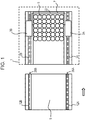
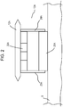
- a conveying device includes first guide rails 2A and 2B and second guide rails 12A and 12B for being connected to the corresponding first guide rails 2A and 2B, as shown in Fig. 1 ; a movable holding part 13A that holds the second guide rail 12A such that the second guide rail 12A is movable in transverse directions with respect to longitudinal directions of the second guide rail 12A as shown in Figs. 2 , 3 , and 4 ; and moving parts 3A and 3B that move by being guided by the corresponding first guide rails 2A and 2B and the corresponding second guide rails 12A and 12B as shown in Figs. 5 and 6 .
- the first guide rails 2A and 2B are disposed, for example, inside a furnace 1.
- the furnace 1 is, for example, a temperature control furnace having a space in which articles 5 are disposed and where the temperature is controlled.
- the temperature control furnace may be, for example, a freezing drying furnace.
- the articles 5 are, for example, vial containers into which medicines are injected.
- the furnace 1 is a freezing drying furnace, the articles 5 are disposed on a table 7 inside the furnace 1, and, for example, the medicines inside the articles 5 are frozen and dried.
- the table 7 is, for example, a shelf board.
- the first guide rails 2A and 2B are disposed along the table 7 where the articles 5 are disposed.
- the first guide rails 2A and 2B are held by corresponding fixing holding members such that the first guide rails 2A and 2B do not move in transverse directions with respect to longitudinal directions of the first guide rails 2A and 2B.
- Transverse directions with respect to longitudinal directions of the first guide rails 2A and 2B are directions perpendicular to the longitudinal directions of the first guide rails 2A and 2B and parallel to a surface of the table 7.
- the second guide rails 12A and 12B are disposed outside the furnace 1.
- the second guide rails 12A and 12B are disposed on a bridge 9.
- a surface of the bridge 9 is parallel to the surface of the table 7.
- the bridge 9 is movable, and, when the door of the furnace 1 is closed, the bridge 9 is separated from the furnace 1 as shown in Fig. 1 .
- the second guide rails 12A and 12B are separated from the corresponding first guide rails 2A and 2B.
- the bridge 9 approaches and comes into contact with the table 7 inside the furnace 1.
- the second guide rails 12A and 12B are connected to the corresponding first guide rails 2A and 2B.
- the movable holding part 13A that holds the second guide rail 12A includes a first deformable member 23A and a second deformable member 23B that are disposed parallel to the longitudinal directions of the second guide rail 12A and that are deformable in the transverse directions with respect to the longitudinal directions of the second guide rail A.
- Transverse directions with respect to the longitudinal directions of the second guide rail A are directions perpendicular to the longitudinal directions of the second guide rail A and parallel to the surface of the bridge 9.
- the second guide rail 2A is disposed on the first deformable member 23A and the second deformable member 23B.
- the first deformable member 23A and the second deformable member 23B are each plate-shaped and are each made of a flexible material.
- a lower portion of the second guide rail 2A has a convex structure, and a top portion of the first deformable member 23A and a top portion of the second deformable member 23B are fixed to corresponding side surfaces of the convex structure of the lower portion of the second guide rail 2A.
- the convex structure of the lower portion of the second guide rail 2A may be integrated with or may be separable from other portions.
- a lower portion of the first deformable member 23A and a lower portion of the second deformable member 23B are, for example, fixed to corresponding side surfaces of a fixing member 25A fixed to the bridge 9.
- the first deformable member 23A and the second deformable member 23B are flexed in the same direction and by, for example, the same amount. Therefore, the second guide rail 2A moves substantially parallel to the transverse direction.
- the second guide rail 12B shown in Fig. 1 is also held by a movable holding part.
- a first coupler is provided at an end portion of each of the first guide rails 2A and 2B.
- the first guide rails 2A and 2B may be integrated with or may be separable from the corresponding first couplers.
- a second coupler 26A is provided at an end portion of the second guide rail 12A, and a second coupler 26B may be provided at an end portion of the second guide rail 12B.
- the second guide rails 12A and 12B may be integrated with or may be separable from the corresponding second couplers 26A and 26B.
- the first couplers and the corresponding second couplers 26A and 26B are coupled when the bridge 9 has approached the table 7.
- the first couplers 26A and 26B each have a protruding structure
- the first couplers each have a concave structure that is fitted to its corresponding protruding structure.
- each first coupler has a protruding structure that is fitted to its corresponding concave structure.
- a contact member 22 for moving the articles 5 on the table 7 and the bridge 9 by coming into contact with the articles 5 is connected at a location between the moving parts 3A and 3B.
- the moving parts 3A and 3B move in synchronism with each other along the corresponding first guide rails 2A and 2B and along the corresponding second guide rails 12A and 12B, to move the articles 5 into and out of the furnace 1 via the contact member 22.
- the moving parts 3A and 3B may be self-propelled by a linear motor, or may be driven by a magnetic screw (not shown).
- the moving part 3A is capable of smoothly moving from the first guide rail 2A to the second guide rail 12A and vice versa and the moving part 3B is capable of smoothly moving from the first guide rail 2B to the second guide rail 12B and vice versa.
- Figs. 8 and 9 each show an example in which, when the bridge 9 is separated from the table 7, the width between the second guide rails 12A and 12B is narrower than the width between the first guide rails 2A and 2B.
- the width between the second guide rails 12A and 12B is corrected to be the same as the width between the first guide rails 2A and 2B.
- articles to be conveyed into and out of the furnace 1 are not limited to medicines, and may be, for example, food, drinks, or precision components, or various other articles.
- the furnace 1 is not limited to a freezing drying furnace, and may be a fermentation furnace or various other types of furnaces in which suppression of uneven internal temperature distribution and suppression of dust generation are desired.
- a mechanism that moves the moving members may be a direct-driven motor. In this way, it is to be understood that the present invention also encompasses, for example, other embodiments that are not described here.
Landscapes
- Engineering & Computer Science (AREA)
- Mechanical Engineering (AREA)
- General Engineering & Computer Science (AREA)
- Health & Medical Sciences (AREA)
- Life Sciences & Earth Sciences (AREA)
- Molecular Biology (AREA)
- Non-Mechanical Conveyors (AREA)
- Tunnel Furnaces (AREA)
- Framework For Endless Conveyors (AREA)
Abstract
Description
- The present invention relates to a conveyance technology, and, in particular, relates to a conveying device.
-
Patent Literature 1 discloses a conveying device including a moving part that moves an article into and out of a furnace and that is driven by a linear motor. The moving part moves by being guided by guide rails. When closing the door of the furnace, the guide rail inside the furnace and the guide rail outside the furnace are separated from each other. When conveying an article inside the furnace out of the furnace, the door of the furnace is opened, and the guide rail inside the furnace and the guide rail outside the furnace are connected to each other. - PTL 1: Specification of United States Unexamined Patent Application Publication No.
2013/0185952 - When connecting the guide rail inside the furnace and the guide rail outside the furnace to each other, if, in a transverse direction with respect to a longitudinal direction of the guide rail, the guide rail outside the furnace is positioned at a corresponding position, the moving part moves smoothly along a connection portion of the guide rails. However, the position of the guide rail outside the furnace may be displaced in the transverse direction due to, for example, an assembly error or a difference between the temperature inside the furnace and the temperature outside the furnace. Accordingly, it is an object of the present invention to provide a conveying device that is capable of correcting displacement of a guide rail.
- According to an embodiment of the present invention, there is provided a conveying device including a first guide rail, a second guide rail for being connected to the first guide rail, a movable holding part that holds the second guide rail such that the second guide rail is movable in a transverse direction with respect to a longitudinal direction of the second guide rail, and a moving part that moves by being guided by the first guide rail and the second guide rail.
- In the above-described conveying device, the movable holding part may include a deformable member that is disposed parallel to the longitudinal direction of the second guide rail and that is deformable in the transverse direction with respect to the longitudinal direction of the second guide rail, and the second guide rail may be disposed on the deformable member. The deformable member may be plate-shaped. The deformable member may be made of a flexible material.
- In the above-described conveying device, the movable holding part may include a first deformable member and a second deformable member that are disposed parallel to the longitudinal direction of the second guide rail and that are deformable in the transverse direction with respect to the longitudinal direction of the second guide rail, and the second guide rail may be disposed on the first deformable member and the second deformable member. The first deformable member and the second deformable member may each be plate-shaped. The first deformable member and the second deformable member may each be made of a flexible material.
- The above-described conveying device may further include a first coupler that is provided at an end portion of the first guide rail, and a second coupler that is provided at an end portion of the second guide rail and that is capable of being coupled with the first coupler.
- The above-described conveying device may further include a first holding member that holds the first guide rail such that the first guide rail does not move in a transverse direction with respect to a longitudinal direction of the first guide rail.
- In the above-described conveying device, the first guide rail may be disposed inside a furnace, and the second guide rail may be disposed outside the furnace. The first guide rail may be disposed along a table that is disposed inside the furnace. The second guide rail may be disposed on a bridge that is disposed outside the furnace, and the bridge may be movable.
- In the above-described conveying device, the second guide rail may be disposed inside the furnace, and the first guide rail may be disposed outside the furnace. The second guide rail may be disposed along the table that is disposed inside the furnace. The first guide rail may be disposed on the bridge that is disposed outside the furnace, and the bridge may be movable.
- The above-described conveying device may further include a contact member that is connected to the moving part and that is provided for moving an article by coming into contact with the article.
- According to the present invention, it is possible to provide a conveying device that is capable of correcting displacement of a guide rail.
-
-
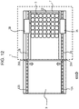
Fig. 1 is a schematic top view of a conveying device according to an embodiment. -
Fig. 2 is a schematic front view of a guide rail, a movable holding part, and a coupler of the conveying device according to the embodiment. -
Fig. 3 is a schematic side view of the guide rail, the movable holding part, and the coupler of the conveying device according to the embodiment. -
Fig. 4 is a schematic front view of the guide rail, the movable holding part, and the coupler of the conveying device according to the embodiment. -
Fig. 5 is a schematic top view of the conveying device according to the embodiment. -
Fig. 6 is a schematic top view of the conveying device according to the embodiment. -
Fig. 7 is a schematic top view of a conveying device according to a reference example of the embodiment. -
Fig. 8 is a schematic top view of the conveying device according to the embodiment. -
Fig. 9 is a schematic top view of the conveying device according to the embodiment. -
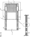
Fig. 10 is a schematic top view of the conveying device according to the embodiment. -
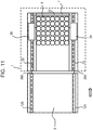
Fig. 11 is a schematic top view of the conveying device according to the embodiment. -
Fig. 12 is a schematic top view of the conveying device according to the embodiment. - An embodiment of the present invention is described below. In the description of the figures below, the same or like portions are denoted by using the same or like symbols. However, the figures are schematic figures. Therefore, for example, specific dimensions should be determined in light of the description below. Naturally, portions having different dimensional relationships and proportions are included even among different figures.
- A conveying device according to the embodiment includes
first guide rails second guide rails first guide rails Fig. 1 ; amovable holding part 13A that holds thesecond guide rail 12A such that thesecond guide rail 12A is movable in transverse directions with respect to longitudinal directions of thesecond guide rail 12A as shown inFigs. 2 ,3 , and4 ; and movingparts first guide rails second guide rails Figs. 5 and6 . - The
first guide rails furnace 1. Thefurnace 1 is, for example, a temperature control furnace having a space in whicharticles 5 are disposed and where the temperature is controlled. The temperature control furnace may be, for example, a freezing drying furnace. Thearticles 5 are, for example, vial containers into which medicines are injected. When thefurnace 1 is a freezing drying furnace, thearticles 5 are disposed on a table 7 inside thefurnace 1, and, for example, the medicines inside thearticles 5 are frozen and dried. The table 7 is, for example, a shelf board. Thefirst guide rails articles 5 are disposed. - The
first guide rails first guide rails first guide rails first guide rails first guide rails - The
second guide rails furnace 1. Thesecond guide rails bridge 9. A surface of thebridge 9 is parallel to the surface of the table 7. Thebridge 9 is movable, and, when the door of thefurnace 1 is closed, thebridge 9 is separated from thefurnace 1 as shown inFig. 1 . At this time, thesecond guide rails first guide rails furnace 1 is open, as shown inFigs. 5 and6 , thebridge 9 approaches and comes into contact with the table 7 inside thefurnace 1. At this time, thesecond guide rails first guide rails - As shown in
Figs. 2 ,3 , and4 , themovable holding part 13A that holds thesecond guide rail 12A includes a firstdeformable member 23A and a second deformable member 23B that are disposed parallel to the longitudinal directions of thesecond guide rail 12A and that are deformable in the transverse directions with respect to the longitudinal directions of the second guide rail A. Transverse directions with respect to the longitudinal directions of the second guide rail A are directions perpendicular to the longitudinal directions of the second guide rail A and parallel to the surface of thebridge 9. Thesecond guide rail 2A is disposed on the firstdeformable member 23A and the second deformable member 23B. For example, the firstdeformable member 23A and the second deformable member 23B are each plate-shaped and are each made of a flexible material. - For example, a lower portion of the
second guide rail 2A has a convex structure, and a top portion of the firstdeformable member 23A and a top portion of the second deformable member 23B are fixed to corresponding side surfaces of the convex structure of the lower portion of thesecond guide rail 2A. The convex structure of the lower portion of thesecond guide rail 2A may be integrated with or may be separable from other portions. A lower portion of the firstdeformable member 23A and a lower portion of the second deformable member 23B, are, for example, fixed to corresponding side surfaces of a fixingmember 25A fixed to thebridge 9. - When a force acting in a transverse direction with respect to the longitudinal directions of the second guide rail A is applied to the
second guide rail 2A, as shown inFig. 4 , the firstdeformable member 23A and the second deformable member 23B are flexed in the same direction and by, for example, the same amount. Therefore, thesecond guide rail 2A moves substantially parallel to the transverse direction. - Similarly to the
second guide rail 12A, thesecond guide rail 12B shown inFig. 1 is also held by a movable holding part. - A first coupler is provided at an end portion of each of the
first guide rails first guide rails second coupler 26A is provided at an end portion of thesecond guide rail 12A, and asecond coupler 26B may be provided at an end portion of thesecond guide rail 12B. Thesecond guide rails second couplers second couplers bridge 9 has approached the table 7. For example, when thesecond couplers second couplers - As shown in
Figs. 5 and6 , acontact member 22 for moving thearticles 5 on the table 7 and thebridge 9 by coming into contact with thearticles 5 is connected at a location between the movingparts parts first guide rails second guide rails articles 5 into and out of thefurnace 1 via thecontact member 22. The movingparts - Here, even if the conveying device is designed and manufactured such that the width between the
first guide rails second guide rails first guide rails second guide rails furnace 1 and the temperature outside thefurnace 1. However, as shown inFig. 7 , when thefirst guide rail 2A and thesecond guide rail 12A are connected to each other and thefirst guide rail 2B and thesecond guide rail 12B are connected to each other while the width between thefirst guide rails second guide rails part 3A to move smoothly from thefirst guide rail 2A to thesecond guide rail 12A and vice versa and for the movingpart 3B to move from thefirst guide rail 2B to thesecond guide rail 12B and vice versa. - In contrast, in the conveying device according to the embodiment, as shown in
Fig. 8 , when thebridge 9 approaches the table 7 inside thefurnace 1, as shown inFig. 9 , thesecond coupler 26A of thesecond guide rail 12A starts to be coupled with the first coupler of thefirst guide rail 2A, and thesecond coupler 26B of thesecond guide rail 12B starts to be coupled with the first coupler of thefirst guide rail 2B. Here, forces acting in the transverse directions based on the difference between the width between thefirst guide rails second guide rails second couplers second guide rails Fig. 10 , when the connection between thefirst guide rail 2A and thesecond guide rail 12A and the connection between thefirst guide rail 2B and thesecond guide rail 12B have been completed, the width between thesecond guide rails first guide rails part 3A is capable of smoothly moving from thefirst guide rail 2A to thesecond guide rail 12A and vice versa and the movingpart 3B is capable of smoothly moving from thefirst guide rail 2B to thesecond guide rail 12B and vice versa. -
Figs. 8 and9 each show an example in which, when thebridge 9 is separated from the table 7, the width between thesecond guide rails first guide rails Figs. 11 and12 , even if the width between thesecond guide rails first guide rails first guide rail 2A and thesecond guide rail 12A and the connection between thefirst guide rail 2B and thesecond guide rail 12B have been completed, the width between thesecond guide rails first guide rails - Although the present invention has been described on the basis of an embodiment as in the foregoing description, the description and figures that define part of this disclosure are not to be construed as limiting the invention. On the basis of this disclosure, various alternative embodiments, examples, and operational technologies should be apparent to any person having ordinary skill in the art. For example, articles to be conveyed into and out of the
furnace 1 are not limited to medicines, and may be, for example, food, drinks, or precision components, or various other articles. Thefurnace 1 is not limited to a freezing drying furnace, and may be a fermentation furnace or various other types of furnaces in which suppression of uneven internal temperature distribution and suppression of dust generation are desired. A mechanism that moves the moving members may be a direct-driven motor. In this way, it is to be understood that the present invention also encompasses, for example, other embodiments that are not described here. -
- 1
- furnace
- 2A, 2B, 12A, 12B
- guide rail
- 3A, 3B
- moving part
- 5
- article
- 7
- table
- 9
- bridge
- 13A
- movable holding part
- 22
- contact member
- 23A, 24A
- deformable member
- 25A
- fixing member
- 26A, 26B
- coupler
Claims (10)
- A conveying device comprising:a first guide rail;a second guide rail for being connected to the first guide rail;a movable holding part that holds the second guide rail such that the second guide rail is movable in a transverse direction with respect to a longitudinal direction of the second guide rail; anda moving part that moves by being guided by the first guide rail and the second guide rail.
- The conveying device according to Claim 1, wherein the movable holding part includes
a deformable member that is disposed parallel to the longitudinal direction of the second guide rail and that is deformable in the transverse direction with respect to the longitudinal direction of the second guide rail, and
wherein the second guide rail is disposed on the deformable member. - The conveying device according to Claim 2, wherein the deformable member is plate-shaped.
- The conveying device according to Claim 2 or Claim 3, wherein the deformable member is made of a flexible material.
- The conveying device according to any one of Claims 1 to 4, further comprisinga first coupler that is provided at an end portion of the first guide rail, anda second coupler that is provided at an end portion of the second guide rail and that is capable of being coupled with the first coupler.
- The conveying device according to any one of Claims 1 to 5, further comprising
a first holding member that holds the first guide rail such that the first guide rail does not move in a transverse direction with respect to a longitudinal direction of the first guide rail. - The conveying device according to Claim 1, wherein the first guide rail is disposed inside a furnace, and the second guide rail is disposed outside the furnace.
- The conveying device according to Claim 7, wherein the first guide rail is disposed along a table that is disposed inside the furnace.
- The conveying device according to Claim 7, wherein the second guide rail is disposed on a bridge that is disposed outside the furnace, and the bridge is movable.
- The conveying device according to Claim 1, further comprising a contact member that is connected to the moving part and that is provided for moving an article by coming into contact with the article.
Applications Claiming Priority (1)
| Application Number | Priority Date | Filing Date | Title |
|---|---|---|---|
| PCT/JP2016/078268 WO2018055763A1 (en) | 2016-09-26 | 2016-09-26 | Conveying device |
Publications (3)
| Publication Number | Publication Date |
|---|---|
| EP3517462A1 true EP3517462A1 (en) | 2019-07-31 |
| EP3517462A4 EP3517462A4 (en) | 2020-07-15 |
| EP3517462B1 EP3517462B1 (en) | 2023-08-09 |
Family
ID=61689453
Family Applications (1)
| Application Number | Title | Priority Date | Filing Date |
|---|---|---|---|
| EP16916830.9A Active EP3517462B1 (en) | 2016-09-26 | 2016-09-26 | Conveying device |
Country Status (4)
| Country | Link |
|---|---|
| US (1) | US10703574B2 (en) |
| EP (1) | EP3517462B1 (en) |
| CN (1) | CN109789973B (en) |
| WO (1) | WO2018055763A1 (en) |
Families Citing this family (2)
| Publication number | Priority date | Publication date | Assignee | Title |
|---|---|---|---|---|
| CN109110403B (en) * | 2018-06-13 | 2020-07-24 | 连云港市第一人民医院 | A medicine box conveying structure in a medical electronic medicine dispensing equipment |
| KR102852651B1 (en) * | 2021-02-23 | 2025-08-29 | 주식회사 엘지에너지솔루션 | Transport apparatus for unit cell |
Family Cites Families (17)
| Publication number | Priority date | Publication date | Assignee | Title |
|---|---|---|---|---|
| US961461A (en) * | 1908-08-25 | 1910-06-14 | J W Kennedy | Railway-rail joint. |
| GB191510547A (en) * | 1915-07-20 | 1915-10-21 | John Peter Schoelerman | Improvements in and relating to Railway Rail Joints. |
| DE2162728A1 (en) * | 1971-12-17 | 1973-06-20 | Franz Dipl Ing Hegenbarth | LANE CHANGE SYSTEM FOR RAIL VEHICLES |
| US3827549A (en) * | 1973-03-16 | 1974-08-06 | Hunter Automated Mach Corp | Extended cooling conveyor |
| JPS58180500U (en) * | 1982-05-28 | 1983-12-02 | 株式会社明電舎 | Processing room shield door |
| DE9001612U1 (en) * | 1989-04-07 | 1990-04-19 | Finn-Aqua Santasalo-Sohlberg GmbH, 50354 Hürth | Device for loading and unloading a freeze-drying device |
| JPH06174895A (en) * | 1992-12-02 | 1994-06-24 | Power Reactor & Nuclear Fuel Dev Corp | Melting facility for processing radioactive metal waste |
| US6245189B1 (en) * | 1994-12-05 | 2001-06-12 | Nordson Corporation | High Throughput plasma treatment system |
| JPH10115698A (en) * | 1996-10-14 | 1998-05-06 | Ishikawajima Harima Heavy Ind Co Ltd | Canister transport container |
| EP1079023A3 (en) * | 1999-08-23 | 2001-03-07 | Tae-Woong Choi | Elastic rail pad |
| JP2002302378A (en) * | 2001-04-03 | 2002-10-18 | Fuji Seisakusho:Kk | Hoisting guide rail connecting device |
| DE10307571A1 (en) * | 2003-02-22 | 2004-09-02 | Steris Gmbh | Furnishing with a footprint |
| DE102010047744A1 (en) | 2010-10-11 | 2012-04-12 | Martin Christ Gefriertrocknungsanlagen Gmbh | Loading and unloading device for a freeze-drying plant |
| ES2626445T3 (en) * | 2012-03-14 | 2017-07-25 | I.M.A. Industria Macchine Automatiche S.P.A. | Device for moving containers |
| JP5936981B2 (en) * | 2012-10-04 | 2016-06-22 | 住友重機械工業株式会社 | Rail base |
| ITMI20131016A1 (en) * | 2013-06-19 | 2014-12-20 | I M A Ind Macchine Automatic He S P A | FEEDING SYSTEM IN A LIOFILIZING MACHINE FOR THE PHARMACEUTICAL SECTOR |
| US9534842B1 (en) * | 2016-02-27 | 2017-01-03 | Usnr, Llc | Kiln cart pusher |
-
2016
- 2016-09-26 EP EP16916830.9A patent/EP3517462B1/en active Active
- 2016-09-26 US US16/336,627 patent/US10703574B2/en active Active
- 2016-09-26 WO PCT/JP2016/078268 patent/WO2018055763A1/en not_active Ceased
- 2016-09-26 CN CN201680089584.1A patent/CN109789973B/en active Active
Also Published As
| Publication number | Publication date |
|---|---|
| WO2018055763A1 (en) | 2018-03-29 |
| CN109789973A (en) | 2019-05-21 |
| US20200055674A1 (en) | 2020-02-20 |
| EP3517462A4 (en) | 2020-07-15 |
| EP3517462B1 (en) | 2023-08-09 |
| US10703574B2 (en) | 2020-07-07 |
| CN109789973B (en) | 2021-06-25 |
Similar Documents
| Publication | Publication Date | Title |
|---|---|---|
| WO2008152245A3 (en) | Shuttle conveyor with tray for a storage and/or logistics preparation warehouse | |
| US11434055B2 (en) | Fastening system | |
| US9604795B2 (en) | Transport device for conveying products | |
| US9061838B2 (en) | Method for operating an electromagnetic transfer system, and transfer system | |
| US10703574B2 (en) | Conveying device | |
| US10130001B2 (en) | Slide rail assembly and bracket device thereof | |
| BRPI0703998A (en) | ceramic sanitary ware manufacturing equipment | |
| CN110650654A (en) | Furniture system | |
| CN110035965B (en) | Conveyor system | |
| MXPA04003375A (en) | System for selectively storing and reintroducing parts into an industrial assembly line. | |
| US20170135474A1 (en) | Slide rail assembly | |
| DE502004003655D1 (en) | Conveyor system, in particular an airport baggage conveyor system, for containers | |
| MX2012007829A (en) | Product dispenser. | |
| BR9803945A (en) | Luggage pushing device, system and method of use | |
| US10418797B2 (en) | Wire harness protector | |
| Qiu et al. | Finite-time synchronization of coupled Cohen–Grossberg neural networks with and without coupling delays | |
| US20070190814A1 (en) | Closure device with a movable flap | |
| US20120217135A1 (en) | Stop device | |
| US11078023B2 (en) | Guiding device for bulk goods conveyors | |
| WO2017198771A3 (en) | Divider conveyor | |
| CN104685239A (en) | Mounting rail for guide carriages for profile rail-roller guides | |
| CN108141977B (en) | Stopper Devices and Units | |
| CN112932117B (en) | Slide rail assembly and its return device | |
| FR3037538B1 (en) | RIDEAU SEGMENTS FOR CLOSING AN ACCESS TO A COMPARTMENT OF A GOODS TRANSPORT VEHICLE | |
| CN111059234A (en) | Chain guide |
Legal Events
| Date | Code | Title | Description |
|---|---|---|---|
| STAA | Information on the status of an ep patent application or granted ep patent |
Free format text: STATUS: THE INTERNATIONAL PUBLICATION HAS BEEN MADE |
|
| PUAI | Public reference made under article 153(3) epc to a published international application that has entered the european phase |
Free format text: ORIGINAL CODE: 0009012 |
|
| STAA | Information on the status of an ep patent application or granted ep patent |
Free format text: STATUS: REQUEST FOR EXAMINATION WAS MADE |
|
| 17P | Request for examination filed |
Effective date: 20190326 |
|
| AK | Designated contracting states |
Kind code of ref document: A1 Designated state(s): AL AT BE BG CH CY CZ DE DK EE ES FI FR GB GR HR HU IE IS IT LI LT LU LV MC MK MT NL NO PL PT RO RS SE SI SK SM TR |
|
| AX | Request for extension of the european patent |
Extension state: BA ME |
|
| DAV | Request for validation of the european patent (deleted) | ||
| DAX | Request for extension of the european patent (deleted) | ||
| A4 | Supplementary search report drawn up and despatched |
Effective date: 20200617 |
|
| RIC1 | Information provided on ipc code assigned before grant |
Ipc: B65G 25/00 20060101AFI20200611BHEP |
|
| STAA | Information on the status of an ep patent application or granted ep patent |
Free format text: STATUS: EXAMINATION IS IN PROGRESS |
|
| 17Q | First examination report despatched |
Effective date: 20220517 |
|
| GRAP | Despatch of communication of intention to grant a patent |
Free format text: ORIGINAL CODE: EPIDOSNIGR1 |
|
| STAA | Information on the status of an ep patent application or granted ep patent |
Free format text: STATUS: GRANT OF PATENT IS INTENDED |
|
| INTG | Intention to grant announced |
Effective date: 20230228 |
|
| GRAS | Grant fee paid |
Free format text: ORIGINAL CODE: EPIDOSNIGR3 |
|
| GRAA | (expected) grant |
Free format text: ORIGINAL CODE: 0009210 |
|
| STAA | Information on the status of an ep patent application or granted ep patent |
Free format text: STATUS: THE PATENT HAS BEEN GRANTED |
|
| AK | Designated contracting states |
Kind code of ref document: B1 Designated state(s): AL AT BE BG CH CY CZ DE DK EE ES FI FR GB GR HR HU IE IS IT LI LT LU LV MC MK MT NL NO PL PT RO RS SE SI SK SM TR |
|
| REG | Reference to a national code |
Ref country code: GB Ref legal event code: FG4D |
|
| REG | Reference to a national code |
Ref country code: CH Ref legal event code: EP |
|
| REG | Reference to a national code |
Ref country code: IE Ref legal event code: FG4D |
|
| REG | Reference to a national code |
Ref country code: DE Ref legal event code: R096 Ref document number: 602016081864 Country of ref document: DE |
|
| REG | Reference to a national code |
Ref country code: LT Ref legal event code: MG9D |
|
| REG | Reference to a national code |
Ref country code: NL Ref legal event code: MP Effective date: 20230809 |
|
| REG | Reference to a national code |
Ref country code: AT Ref legal event code: MK05 Ref document number: 1597322 Country of ref document: AT Kind code of ref document: T Effective date: 20230809 |
|
| PG25 | Lapsed in a contracting state [announced via postgrant information from national office to epo] |
Ref country code: GR Free format text: LAPSE BECAUSE OF FAILURE TO SUBMIT A TRANSLATION OF THE DESCRIPTION OR TO PAY THE FEE WITHIN THE PRESCRIBED TIME-LIMIT Effective date: 20231110 |
|
| PG25 | Lapsed in a contracting state [announced via postgrant information from national office to epo] |
Ref country code: IS Free format text: LAPSE BECAUSE OF FAILURE TO SUBMIT A TRANSLATION OF THE DESCRIPTION OR TO PAY THE FEE WITHIN THE PRESCRIBED TIME-LIMIT Effective date: 20231209 |
|
| PG25 | Lapsed in a contracting state [announced via postgrant information from national office to epo] |
Ref country code: SE Free format text: LAPSE BECAUSE OF FAILURE TO SUBMIT A TRANSLATION OF THE DESCRIPTION OR TO PAY THE FEE WITHIN THE PRESCRIBED TIME-LIMIT Effective date: 20230809 Ref country code: RS Free format text: LAPSE BECAUSE OF FAILURE TO SUBMIT A TRANSLATION OF THE DESCRIPTION OR TO PAY THE FEE WITHIN THE PRESCRIBED TIME-LIMIT Effective date: 20230809 Ref country code: PT Free format text: LAPSE BECAUSE OF FAILURE TO SUBMIT A TRANSLATION OF THE DESCRIPTION OR TO PAY THE FEE WITHIN THE PRESCRIBED TIME-LIMIT Effective date: 20231211 Ref country code: NO Free format text: LAPSE BECAUSE OF FAILURE TO SUBMIT A TRANSLATION OF THE DESCRIPTION OR TO PAY THE FEE WITHIN THE PRESCRIBED TIME-LIMIT Effective date: 20231109 Ref country code: NL Free format text: LAPSE BECAUSE OF FAILURE TO SUBMIT A TRANSLATION OF THE DESCRIPTION OR TO PAY THE FEE WITHIN THE PRESCRIBED TIME-LIMIT Effective date: 20230809 Ref country code: LV Free format text: LAPSE BECAUSE OF FAILURE TO SUBMIT A TRANSLATION OF THE DESCRIPTION OR TO PAY THE FEE WITHIN THE PRESCRIBED TIME-LIMIT Effective date: 20230809 Ref country code: LT Free format text: LAPSE BECAUSE OF FAILURE TO SUBMIT A TRANSLATION OF THE DESCRIPTION OR TO PAY THE FEE WITHIN THE PRESCRIBED TIME-LIMIT Effective date: 20230809 Ref country code: IS Free format text: LAPSE BECAUSE OF FAILURE TO SUBMIT A TRANSLATION OF THE DESCRIPTION OR TO PAY THE FEE WITHIN THE PRESCRIBED TIME-LIMIT Effective date: 20231209 Ref country code: HR Free format text: LAPSE BECAUSE OF FAILURE TO SUBMIT A TRANSLATION OF THE DESCRIPTION OR TO PAY THE FEE WITHIN THE PRESCRIBED TIME-LIMIT Effective date: 20230809 Ref country code: GR Free format text: LAPSE BECAUSE OF FAILURE TO SUBMIT A TRANSLATION OF THE DESCRIPTION OR TO PAY THE FEE WITHIN THE PRESCRIBED TIME-LIMIT Effective date: 20231110 Ref country code: FI Free format text: LAPSE BECAUSE OF FAILURE TO SUBMIT A TRANSLATION OF THE DESCRIPTION OR TO PAY THE FEE WITHIN THE PRESCRIBED TIME-LIMIT Effective date: 20230809 Ref country code: AT Free format text: LAPSE BECAUSE OF FAILURE TO SUBMIT A TRANSLATION OF THE DESCRIPTION OR TO PAY THE FEE WITHIN THE PRESCRIBED TIME-LIMIT Effective date: 20230809 |
|
| PG25 | Lapsed in a contracting state [announced via postgrant information from national office to epo] |
Ref country code: PL Free format text: LAPSE BECAUSE OF FAILURE TO SUBMIT A TRANSLATION OF THE DESCRIPTION OR TO PAY THE FEE WITHIN THE PRESCRIBED TIME-LIMIT Effective date: 20230809 |
|
| PG25 | Lapsed in a contracting state [announced via postgrant information from national office to epo] |
Ref country code: ES Free format text: LAPSE BECAUSE OF FAILURE TO SUBMIT A TRANSLATION OF THE DESCRIPTION OR TO PAY THE FEE WITHIN THE PRESCRIBED TIME-LIMIT Effective date: 20230809 |
|
| PG25 | Lapsed in a contracting state [announced via postgrant information from national office to epo] |
Ref country code: SM Free format text: LAPSE BECAUSE OF FAILURE TO SUBMIT A TRANSLATION OF THE DESCRIPTION OR TO PAY THE FEE WITHIN THE PRESCRIBED TIME-LIMIT Effective date: 20230809 Ref country code: RO Free format text: LAPSE BECAUSE OF FAILURE TO SUBMIT A TRANSLATION OF THE DESCRIPTION OR TO PAY THE FEE WITHIN THE PRESCRIBED TIME-LIMIT Effective date: 20230809 Ref country code: ES Free format text: LAPSE BECAUSE OF FAILURE TO SUBMIT A TRANSLATION OF THE DESCRIPTION OR TO PAY THE FEE WITHIN THE PRESCRIBED TIME-LIMIT Effective date: 20230809 Ref country code: EE Free format text: LAPSE BECAUSE OF FAILURE TO SUBMIT A TRANSLATION OF THE DESCRIPTION OR TO PAY THE FEE WITHIN THE PRESCRIBED TIME-LIMIT Effective date: 20230809 Ref country code: DK Free format text: LAPSE BECAUSE OF FAILURE TO SUBMIT A TRANSLATION OF THE DESCRIPTION OR TO PAY THE FEE WITHIN THE PRESCRIBED TIME-LIMIT Effective date: 20230809 Ref country code: CZ Free format text: LAPSE BECAUSE OF FAILURE TO SUBMIT A TRANSLATION OF THE DESCRIPTION OR TO PAY THE FEE WITHIN THE PRESCRIBED TIME-LIMIT Effective date: 20230809 Ref country code: SK Free format text: LAPSE BECAUSE OF FAILURE TO SUBMIT A TRANSLATION OF THE DESCRIPTION OR TO PAY THE FEE WITHIN THE PRESCRIBED TIME-LIMIT Effective date: 20230809 |
|
| REG | Reference to a national code |
Ref country code: CH Ref legal event code: PL |
|
| REG | Reference to a national code |
Ref country code: DE Ref legal event code: R097 Ref document number: 602016081864 Country of ref document: DE |
|
| PG25 | Lapsed in a contracting state [announced via postgrant information from national office to epo] |
Ref country code: LU Free format text: LAPSE BECAUSE OF NON-PAYMENT OF DUE FEES Effective date: 20230926 |
|
| REG | Reference to a national code |
Ref country code: BE Ref legal event code: MM Effective date: 20230930 |
|
| PG25 | Lapsed in a contracting state [announced via postgrant information from national office to epo] |
Ref country code: LU Free format text: LAPSE BECAUSE OF NON-PAYMENT OF DUE FEES Effective date: 20230926 Ref country code: MC Free format text: LAPSE BECAUSE OF FAILURE TO SUBMIT A TRANSLATION OF THE DESCRIPTION OR TO PAY THE FEE WITHIN THE PRESCRIBED TIME-LIMIT Effective date: 20230809 |
|
| PLBE | No opposition filed within time limit |
Free format text: ORIGINAL CODE: 0009261 |
|
| STAA | Information on the status of an ep patent application or granted ep patent |
Free format text: STATUS: NO OPPOSITION FILED WITHIN TIME LIMIT |
|
| REG | Reference to a national code |
Ref country code: IE Ref legal event code: MM4A |
|
| PG25 | Lapsed in a contracting state [announced via postgrant information from national office to epo] |
Ref country code: IE Free format text: LAPSE BECAUSE OF NON-PAYMENT OF DUE FEES Effective date: 20230926 |
|
| 26N | No opposition filed |
Effective date: 20240513 |
|
| PG25 | Lapsed in a contracting state [announced via postgrant information from national office to epo] |
Ref country code: CH Free format text: LAPSE BECAUSE OF NON-PAYMENT OF DUE FEES Effective date: 20230930 |
|
| GBPC | Gb: european patent ceased through non-payment of renewal fee |
Effective date: 20231109 |
|
| PG25 | Lapsed in a contracting state [announced via postgrant information from national office to epo] |
Ref country code: IE Free format text: LAPSE BECAUSE OF NON-PAYMENT OF DUE FEES Effective date: 20230926 Ref country code: FR Free format text: LAPSE BECAUSE OF NON-PAYMENT OF DUE FEES Effective date: 20231009 Ref country code: CH Free format text: LAPSE BECAUSE OF NON-PAYMENT OF DUE FEES Effective date: 20230930 Ref country code: SI Free format text: LAPSE BECAUSE OF FAILURE TO SUBMIT A TRANSLATION OF THE DESCRIPTION OR TO PAY THE FEE WITHIN THE PRESCRIBED TIME-LIMIT Effective date: 20230809 |
|
| PG25 | Lapsed in a contracting state [announced via postgrant information from national office to epo] |
Ref country code: BE Free format text: LAPSE BECAUSE OF NON-PAYMENT OF DUE FEES Effective date: 20230930 |
|
| REG | Reference to a national code |
Ref country code: DE Ref legal event code: R081 Ref document number: 602016081864 Country of ref document: DE Owner name: AZBIL TELSTAR TECHNOLOGIES. S.L., ES Free format text: FORMER OWNER: AZBIL CORPORATION, TOKYO, JP Ref country code: DE Ref legal event code: R081 Ref document number: 602016081864 Country of ref document: DE Owner name: SYNTEGON TELSTAR TECHNOLOGIES, S.L.U., ES Free format text: FORMER OWNER: AZBIL CORPORATION, TOKYO, JP |
|
| PG25 | Lapsed in a contracting state [announced via postgrant information from national office to epo] |
Ref country code: GB Free format text: LAPSE BECAUSE OF NON-PAYMENT OF DUE FEES Effective date: 20231109 |
|
| PG25 | Lapsed in a contracting state [announced via postgrant information from national office to epo] |
Ref country code: GB Free format text: LAPSE BECAUSE OF NON-PAYMENT OF DUE FEES Effective date: 20231109 |
|
| PG25 | Lapsed in a contracting state [announced via postgrant information from national office to epo] |
Ref country code: BG Free format text: LAPSE BECAUSE OF FAILURE TO SUBMIT A TRANSLATION OF THE DESCRIPTION OR TO PAY THE FEE WITHIN THE PRESCRIBED TIME-LIMIT Effective date: 20230809 |
|
| PG25 | Lapsed in a contracting state [announced via postgrant information from national office to epo] |
Ref country code: BG Free format text: LAPSE BECAUSE OF FAILURE TO SUBMIT A TRANSLATION OF THE DESCRIPTION OR TO PAY THE FEE WITHIN THE PRESCRIBED TIME-LIMIT Effective date: 20230809 |
|
| PGFP | Annual fee paid to national office [announced via postgrant information from national office to epo] |
Ref country code: IT Payment date: 20241227 Year of fee payment: 10 |
|
| PG25 | Lapsed in a contracting state [announced via postgrant information from national office to epo] |
Ref country code: CY Free format text: LAPSE BECAUSE OF FAILURE TO SUBMIT A TRANSLATION OF THE DESCRIPTION OR TO PAY THE FEE WITHIN THE PRESCRIBED TIME-LIMIT; INVALID AB INITIO Effective date: 20160926 |
|
| REG | Reference to a national code |
Ref country code: DE Ref legal event code: R081 Ref document number: 602016081864 Country of ref document: DE Owner name: SYNTEGON TELSTAR TECHNOLOGIES, S.L.U., ES Free format text: FORMER OWNER: AZBIL TELSTAR TECHNOLOGIES. S.L., TERRASSA, ES |
|
| PG25 | Lapsed in a contracting state [announced via postgrant information from national office to epo] |
Ref country code: HU Free format text: LAPSE BECAUSE OF FAILURE TO SUBMIT A TRANSLATION OF THE DESCRIPTION OR TO PAY THE FEE WITHIN THE PRESCRIBED TIME-LIMIT; INVALID AB INITIO Effective date: 20160926 |
|
| PGFP | Annual fee paid to national office [announced via postgrant information from national office to epo] |
Ref country code: DE Payment date: 20250919 Year of fee payment: 10 |
|
| PG25 | Lapsed in a contracting state [announced via postgrant information from national office to epo] |
Ref country code: TR Free format text: LAPSE BECAUSE OF FAILURE TO SUBMIT A TRANSLATION OF THE DESCRIPTION OR TO PAY THE FEE WITHIN THE PRESCRIBED TIME-LIMIT Effective date: 20230809 |