EP3517433A1 - Apparatus for providing attitude reference for vehicle passengers - Google Patents
Apparatus for providing attitude reference for vehicle passengers Download PDFInfo
- Publication number
- EP3517433A1 EP3517433A1 EP19163941.8A EP19163941A EP3517433A1 EP 3517433 A1 EP3517433 A1 EP 3517433A1 EP 19163941 A EP19163941 A EP 19163941A EP 3517433 A1 EP3517433 A1 EP 3517433A1
- Authority
- EP
- European Patent Office
- Prior art keywords
- occupant
- monitor
- monitors
- eye
- video
- Prior art date
- Legal status (The legal status is an assumption and is not a legal conclusion. Google has not performed a legal analysis and makes no representation as to the accuracy of the status listed.)
- Granted
Links
Images



Classifications
-
- B—PERFORMING OPERATIONS; TRANSPORTING
- B64—AIRCRAFT; AVIATION; COSMONAUTICS
- B64D—EQUIPMENT FOR FITTING IN OR TO AIRCRAFT; FLIGHT SUITS; PARACHUTES; ARRANGEMENT OR MOUNTING OF POWER PLANTS OR PROPULSION TRANSMISSIONS IN AIRCRAFT
- B64D11/00—Passenger or crew accommodation; Flight-deck installations not otherwise provided for
- B64D11/0015—Arrangements for entertainment or communications, e.g. radio, television
-
- G—PHYSICS
- G06—COMPUTING OR CALCULATING; COUNTING
- G06V—IMAGE OR VIDEO RECOGNITION OR UNDERSTANDING
- G06V20/00—Scenes; Scene-specific elements
- G06V20/50—Context or environment of the image
- G06V20/56—Context or environment of the image exterior to a vehicle by using sensors mounted on the vehicle
-
- H—ELECTRICITY
- H04—ELECTRIC COMMUNICATION TECHNIQUE
- H04N—PICTORIAL COMMUNICATION, e.g. TELEVISION
- H04N7/00—Television systems
- H04N7/18—Closed-circuit television [CCTV] systems, i.e. systems in which the video signal is not broadcast
- H04N7/181—Closed-circuit television [CCTV] systems, i.e. systems in which the video signal is not broadcast for receiving images from a plurality of remote sources
Definitions
- the invention relates generally to the field of vehicular travel and more particularly to a video system and apparatus which informs one or more passengers seated in an enclosed windowless suite in a vehicle of the vehicle's attitude and changes in vehicle attitude (e.g. pitching nose up or nose down, or yawing or rolling to the right or left.)
- windowless suites are now found in luxury long haul aircraft cabin suites of commercial aircraft.
- Forward looking landscape cameras do not provide a reliable attitude reference during takeoff maneuvers because the nose of the aircraft is quickly pointed skyward, leaving no observable horizon. As a result, the disappearance of the horizon as the airplane rotates on takeoff can be disorienting to passengers. Downward looking cameras also do not provide an intuitive attitude reference to the passengers. Furthermore, the video screen displaying these images serves a variety of information and entertainment purposes and is rarely turned to the camera mode, rendering it unlikely to relieve motion-oriented discomfort resulting from a cause unrecognized by the passenger.
- the present invention avoids these problems by restricting system use to a single point of view, and providing mathematical guidance on both the orientation and field of view for each image shown.
- the present invention emulates the windows typically found in commercial aircraft in which passengers seated in enclosed cabins can be expected to have experienced on previous flights. There is no need for passengers to focus their attention on the video monitors of the present invention to be provided the desired attitude reference. It is sufficient that they are subconsciously informed of changing airplane attitude through their peripheral vision.
- the present invention also includes a video reference system for a single viewer in a private cabin in an aircraft, ship or other vehicle, the motion of which might induce motion sickness or motion-related discomfort.
- an apparatus adapted to provide visual attitude reference to occupants seated in an inboard area of a cabin of a vehicle, that includes at least one interior partition positioned in the cabin in proximity to the occupants and at least one video camera mounted on the vehicle for capturing an electronic image of an environment exterior to the vehicle.
- At least one video monitor is adapted to serve as a virtual window mounted on the at least one interior partition in a substantially vertical and substantially parallel direction relative to a direction of forward travel of the vehicle in viewing proximity to the occupant, and further adapted to receive the electronic image from the at least one video camera and provide to the occupant an image of the environment external to the vehicle to the occupant.
- the cabin is without transparent cabin windows that provide a view of the actual environment external to the vehicle.
- the cabin includes transparent cabin windows that provide a view of the actual environment external to the vehicle to occupants seated in proximity to the transparent cabin windows but not to occupants in proximity to the at least one interior partition.
- an apparatus provides attitude reference to one or more passengers in an enclosed windowless cabin of a vehicle.
- the apparatus includes one or more video monitors mounted substantially vertical and substantially parallel to a direction of forward travel of the vehicle.
- the apparatus includes one or more video cameras positioned in an outer wall of the vehicle and arranged to capture video of the view of the environment external to the vehicle that is generally perpendicular to the direction of forward travel of the vehicle.
- the apparatus may further include a computer connecting the one or more video cameras with the one or more video monitors.
- the apparatus may yet further include one or more sensors configured to provide occupant location data to the computer.
- the video cameras and the video monitors are positioned at substantially the same lateral position along a longitudinal length of the vehicle.
- the computer utilizes occupant location data to determine the video displayed on the monitors. Further, each of the monitors, based on the occupant location data as determined by the computer, displays a different image oriented in a direction substantially perpendicular to an occupant's line of sight to the monitor displaying that image.
- the apparatus may include at least one video monitor mounted substantially vertical and substantially parallel to a direction of forward travel of the vehicle and in viewing proximity to the occupant and adapted to provide a lateral view of an environment external to the vehicle to the occupant.
- the video monitor or monitors may be positioned in lateral proximity to a forward-facing occupant.
- the sensors which provide the occupant location data are selected from the group consisting of: sensors monitoring the position of the seat supporting the occupant; an optical system designed to locate the occupant's head; and a head rest sensor monitoring the position of the occupant's head on a head rest of the seat.
- the different image displayed on each of the monitors provides a substantially same field of view to the occupant of the enclosed windowless cabin as would be experienced by a similarly situated occupant of an enclosed cabin having windows.
- multiple monitors are provided, and display a different image oriented in a direction substantially perpendicular to an occupant's line of sight to the monitor displaying that image.
- the number of monitors is equal to three.
- each image has a vertical angular field of view substantially equal to the vertical angle subtended by the corresponding monitor from an occupant's eye position.
- the line of sight originates at an occupant's eye position while seated in a position required for taxi, takeoff and landing.
- the line of sight originates at an occupant's eye position as estimated using sensors monitoring the position of the seat supporting the occupant.
- the line of sight originates at an occupant's eye position as estimated using an optical system designed to locate the occupant's head.
- an enclosed aircraft cabin adapted to seat a single individual or two individuals side-by-side is provided, and incorporates the claimed video system.
- Fig.1 illustrates a prior art aircraft cabin with enclosed individual suites 20A, 20B, 20C, 20D, 30A, 30B, 30C, 30D. Each of the suites is accessible via door 60 for each suite. Note the blocked windows 40, 42. Passengers in suites 20A, 20D, 30A, and 30D have direct window access via windows 22A, 24A, 26A, 22D, 24D, 26D, 32A, 34A, 36A, 32D, 34D, and 36D, respectively. However, in this interior environment of Fig.1 , the passengers in suites 20B, 20C, 30B and 30C are without any visual attitude reference.
- video monitors 22B, 24B, 26B, 22C, 24C, 26C, 32B, 34B, 36B, 32C, 34C, and 36C are provided, as indicated, for passengers seated in enclosed suites 20B, 20C, 30B, and 30C, respectively, and, as shown in Figs. 5 and 6 , the orientation of the monitors emulates the orientation of standard aircraft passenger windows.
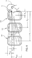
- This orientation takes advantage of the occupant's 70 experience with "real" windows, such as real windows 22A, 24A, 26A, 32A, 34A, 36A, 22D, 24D, 26D, 32D, 34D, and 36D, to provide an intuitive attitude reference. Replication of this experience is depicted in Fig. 6 .
- the video monitors, 22B, 24B, 26B, 22C, 24C, 26C, 32B, 34B, 36B, 32C, 34C, 36C, of the present invention 10 are intended to serve the single purpose of providing an external view (as shown in Fig. 6 ) and attitude reference and should not, therefore, also be used to provide informational or entertainment content.
- a preferred embodiment of the invention employs a separate camera located at camera position 50, 52, for each viewing angle. These cameras are positioned 50, 52 in unblocked windows 44, 46 respectively. (These windows are blocked in prior art - see Fig. 1 ). It is understood that distinct images with the desired viewing angles can be extracted electronically from a single image with a field of view wide enough to encompass the desired viewing angles. However, each of these distinct images would comprise such a small fraction of the original image that the resulting resolution would be poor.
- the orientation of a camera image for the present invention can be D° (downward) relative to a horizontal plane and F° (forward) relative to a transverse plane.
- the angle values D° and F° will be different for each monitor having a different relationship to the viewer, which can be represented as D 1 °, shown in Figs. 5 and 6 , and F 1 ° shown in Figs. 3 and 4 , for the forwardmost monitor in a cabin, D 2 ° and F 2 ° for the second forwardmost monitor in a cabin and so forth.
- D 1 ° shown in Figs. 5 and 6
- F 1 ° shown in Figs. 3 and 4
- the field of view V° in Figs. 5 and 6 when measured as the viewing angle presented on the video monitor, 32B, 34B, 36B, from the upper edge of the monitor, 32B, 34B, 36B, to the lower edge of the monitor, 32B, 34B, 36B, is calculated as the sum of the angle above eye 72 height to the upper edge of the monitor, 32B, 34B, 36B, and the angle below eye 72 height to the lower edge of the monitor, 32B, 34B, 36B, where:
- the preferred embodiment of the invention employs a different camera/lens combination for each desired field of view.
- the invention could employ for all cameras in the system a camera/lens combination optimized for the widest field of view required and reduce the field of view of the images electronically as required.
- the present invention is particularly well suited to a single viewer 70, it will retain some effectiveness for two viewers seated in close proximity with eye 72 positions close to one another as might be found when a couple is seated together on a double seat as shown in Fig. 4 .
- the view through a typical aircraft window changes in both angle and field of view with changes in the eye 72 position of the viewer. For example, as the observer 70 moves aft relative to a window, the view shifts to a more forward-looking view. Similarly, as the viewer moves closer to a window, the field of view through the window defines a larger angle.
- a monitor, 32B, 34B, 36B, emulating a window must display an image that approximates the view the observer would see if the monitor were actually a window. For this reason both the orientation and the field of view of the camera image for the video monitor, 32B, 34B, 36B, must be determined based on the eye position 72 of the viewer relative to the video monitor, 32B, 34B, 36B.
- each of the monitors must present a different image, with the orientation and field of view of each of the images being determined by the viewer's 70 eye position 72 relative to that respective monitor, 32B, 34B, 36B.
- the viewer's 70 eye position 72 is calculated using the headrest 62 position of the viewer's seat 38B when in the upright position used during taxi takeoff and landing (TTL).
- This eye position 72 can be calculated as the seated eye height above the compressed seat cushion and the head length forward of the head rest.
- the present preference for this method derives from the fact that the seated viewer 70 is obliged to have the seat in the TTL position during the periods of flight when the airplane is making the maneuvers likely to cause motion sickness or discomfort.
- seat position sensors including, but not limited to, a recline position sensor, can be employed to estimate the viewer's eye position 72 when the viewer's seat 38B is not in the TTL position.
- a visual system 64 that recognizes and calculates the position of facial features of the occupant 70 such as is commonly used in range-finding cameras can be used to determine the viewer's eye position 72.
- F°, D° and V° can be calculated as described above when using these or other methods of estimating or determining the viewer's 70 eye position 72 and images to be displayed on monitors modified by either mechanical, optical or electronic means to adjust F°, D° and V° as required.
Landscapes
- Engineering & Computer Science (AREA)
- Multimedia (AREA)
- Signal Processing (AREA)
- Aviation & Aerospace Engineering (AREA)
- Physics & Mathematics (AREA)
- General Physics & Mathematics (AREA)
- Theoretical Computer Science (AREA)
- Fittings On The Vehicle Exterior For Carrying Loads, And Devices For Holding Or Mounting Articles (AREA)
Abstract
Description
- The invention relates generally to the field of vehicular travel and more particularly to a video system and apparatus which informs one or more passengers seated in an enclosed windowless suite in a vehicle of the vehicle's attitude and changes in vehicle attitude (e.g. pitching nose up or nose down, or yawing or rolling to the right or left.) Such windowless suites are now found in luxury long haul aircraft cabin suites of commercial aircraft.
- It has long been known that airline passengers seated in window seats report experiencing higher comfort levels than passengers in other cabin areas. See
US Patent 5,611,503 , particularlyFig. 4 . While there may be several reasons for this higher reported comfort level, psychological studies have shown that enabling passengers to be correctly oriented in space is an important contributor to passenger comfort. While some passengers experience acute motion sickness when deprived of visual references informing them of changes in vehicle attitude, a majority of airline passengers experience only a somewhat diminished comfort, the origin of which is unknown to them, when experiencing properly-coordinated maneuvers of a commercial airplane without a visual reference informing them of changes in airplane attitude. - Forward looking and downward looking "landscape" cameras displaying images on a video screen generally forward of the passenger are well known. Static airplane mockups incorporating video screens in lieu of windows are also known. In this and similar known applications, a single image has been replicated on all screens on the same side of the mockup.
- Forward looking landscape cameras do not provide a reliable attitude reference during takeoff maneuvers because the nose of the aircraft is quickly pointed skyward, leaving no observable horizon. As a result, the disappearance of the horizon as the airplane rotates on takeoff can be disorienting to passengers. Downward looking cameras also do not provide an intuitive attitude reference to the passengers. Furthermore, the video screen displaying these images serves a variety of information and entertainment purposes and is rarely turned to the camera mode, rendering it unlikely to relieve motion-oriented discomfort resulting from a cause unrecognized by the passenger.
- While they have been used in static mockups in which motion oriented discomfort is not an issue, emulating a row of aircraft windows with video monitors has never been considered sufficiently attractive for use in an airplane to justify developing and flight testing such a system. For a typical airplane cabin with many occupants and many monitors emulating windows, no viable alternative has been found to repeating the same image on each monitor down the length of a side of the cabin. When an airplane is climbing, repeating the same image in each monitor along a row of windows presents the image of a level flight over a sawtooth landscape. Any such perceived attitude reference is ambiguous or confusing. When an airplane is rolling, monitors farther from the viewer subtend a smaller vertical field of view. Accordingly, to each individual viewer the rear of the airplane appears to be rolling more quickly than the front of the airplane, an appearance more likely to induce motion sickness than alleviate it. The present invention avoids these problems by restricting system use to a single point of view, and providing mathematical guidance on both the orientation and field of view for each image shown.
- To provide an intuitive reference which does not require passenger training to be effective, the present invention emulates the windows typically found in commercial aircraft in which passengers seated in enclosed cabins can be expected to have experienced on previous flights. There is no need for passengers to focus their attention on the video monitors of the present invention to be provided the desired attitude reference. It is sufficient that they are subconsciously informed of changing airplane attitude through their peripheral vision.
The present invention also includes a video reference system for a single viewer in a private cabin in an aircraft, ship or other vehicle, the motion of which might induce motion sickness or motion-related discomfort. - It is therefore an object of the present invention to provide an apparatus and method for providing attitude reference information to vehicle passengers.
- It is another object of the invention to provide an apparatus and method for providing attitude reference information to aircraft passengers without access to direct visual attitude reference, such as passengers in private suites.
- These and other objects and advantages of the invention are achieved by providing an apparatus adapted to provide visual attitude reference to occupants seated in an inboard area of a cabin of a vehicle, that includes at least one interior partition positioned in the cabin in proximity to the occupants and at least one video camera mounted on the vehicle for capturing an electronic image of an environment exterior to the vehicle. At least one video monitor is adapted to serve as a virtual window mounted on the at least one interior partition in a substantially vertical and substantially parallel direction relative to a direction of forward travel of the vehicle in viewing proximity to the occupant, and further adapted to receive the electronic image from the at least one video camera and provide to the occupant an image of the environment external to the vehicle to the occupant.
- According to one embodiment of the invention, the cabin is without transparent cabin windows that provide a view of the actual environment external to the vehicle.
- According to another embodiment of the invention, the cabin includes transparent cabin windows that provide a view of the actual environment external to the vehicle to occupants seated in proximity to the transparent cabin windows but not to occupants in proximity to the at least one interior partition.
- According to one embodiment of the invention, an apparatus provides attitude reference to one or more passengers in an enclosed windowless cabin of a vehicle. The apparatus includes one or more video monitors mounted substantially vertical and substantially parallel to a direction of forward travel of the vehicle. The apparatus includes one or more video cameras positioned in an outer wall of the vehicle and arranged to capture video of the view of the environment external to the vehicle that is generally perpendicular to the direction of forward travel of the vehicle. The apparatus may further include a computer connecting the one or more video cameras with the one or more video monitors. The apparatus may yet further include one or more sensors configured to provide occupant location data to the computer.
- According to such an embodiment, the video cameras and the video monitors are positioned at substantially the same lateral position along a longitudinal length of the vehicle. The computer utilizes occupant location data to determine the video displayed on the monitors. Further, each of the monitors, based on the occupant location data as determined by the computer, displays a different image oriented in a direction substantially perpendicular to an occupant's line of sight to the monitor displaying that image.
- According to another embodiment of the invention, the apparatus may include at least one video monitor mounted substantially vertical and substantially parallel to a direction of forward travel of the vehicle and in viewing proximity to the occupant and adapted to provide a lateral view of an environment external to the vehicle to the occupant.
- According to another embodiment of the invention, the video monitor or monitors may be positioned in lateral proximity to a forward-facing occupant.
- According to one embodiment of the invention, the sensors which provide the occupant location data are selected from the group consisting of: sensors monitoring the position of the seat supporting the occupant; an optical system designed to locate the occupant's head; and a head rest sensor monitoring the position of the occupant's head on a head rest of the seat.
- According to another embodiment of the invention, the different image displayed on each of the monitors provides a substantially same field of view to the occupant of the enclosed windowless cabin as would be experienced by a similarly situated occupant of an enclosed cabin having windows.
- According to one embodiment of the invention, multiple monitors are provided, and display a different image oriented in a direction substantially perpendicular to an occupant's line of sight to the monitor displaying that image.
- According to one embodiment of the invention, the number of monitors is equal to three.
- According to one embodiment of the invention, each image has a vertical angular field of view substantially equal to the vertical angle subtended by the corresponding monitor from an occupant's eye position.
- According to one embodiment of the invention, the line of sight originates at an occupant's eye position while seated in a position required for taxi, takeoff and landing.
- According to one embodiment of the invention, the line of sight originates at an occupant's eye position as estimated using sensors monitoring the position of the seat supporting the occupant.
- According to one embodiment of the invention, the line of sight originates at an occupant's eye position as estimated using an optical system designed to locate the occupant's head.
- According to one embodiment of the invention, an enclosed aircraft cabin adapted to seat a single individual or two individuals side-by-side is provided, and incorporates the claimed video system.
- The present invention is best understood when the following detailed description of the invention is read with reference to the accompanying drawings, in which:
-
Fig.1 is a plan view of a prior art aircraft interior with fully enclosed individual suites; -
Fig. 2 is a plan view of an embodiment of the present invention, providing attitude reference information to aircraft passengers without access to direct visual attitude reference; -
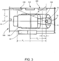
Fig. 3 is an enlarged plan view of a single one of the individual enclosed suites shown inFig. 2 ; and attitude reference information to aircraft passengers without access to direct visual attitude reference; -
Fig. 4 is an enlarged plan view of a single one of the individual enclosed suites shown inFig. 2 but including a second seat; and attitude reference information to aircraft passengers without access to direct visual attitude reference; -
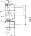
Fig. 5 is a side elevation view showing respective monitor and eye elevation positions for the individual enclosed suite ofFigs. 2 ,3 , and4 ; and -
Fig 6 is a side elevation view showing respective monitor and eye elevation positions for the individual enclosed suite ofFigs. 2 ,3 , and4 and highlighting the replication of windows via the respective monitors. - Referring now to the drawings,
Fig.1 illustrates a prior art aircraft cabin with enclosedindividual suites door 60 for each suite. Note the blockedwindows suites Fig.1 , the passengers insuites - In accordance with a preferred embodiment of the invention as shown in
Figs. 2 ,3 ,4 ,5 , and6 , video monitors 22B, 24B, 26B, 22C, 24C, 26C, 32B, 34B, 36B, 32C, 34C, and 36C are provided, as indicated, for passengers seated inenclosed suites Figs. 5 and6 , the orientation of the monitors emulates the orientation of standard aircraft passenger windows. This orientation takes advantage of the occupant's 70 experience with "real" windows, such asreal windows Fig. 6 . The video monitors, 22B, 24B, 26B, 22C, 24C, 26C, 32B, 34B, 36B, 32C, 34C, 36C, of thepresent invention 10 are intended to serve the single purpose of providing an external view (as shown inFig. 6 ) and attitude reference and should not, therefore, also be used to provide informational or entertainment content. - To provide high resolution images to each monitor, 22B, 24B, 26B, 22C, 24C, 26C, 32B, 34B, 36B, 32C, 34C, 36C, a preferred embodiment of the invention employs a separate camera located at
camera position windows Fig. 1 ). It is understood that distinct images with the desired viewing angles can be extracted electronically from a single image with a field of view wide enough to encompass the desired viewing angles. However, each of these distinct images would comprise such a small fraction of the original image that the resulting resolution would be poor. - As shown in
Figs. 3 ,4 ,5 and6 , the orientation of a camera image for the present invention can be D° (downward) relative to a horizontal plane and F° (forward) relative to a transverse plane. The angle values D° and F° will be different for each monitor having a different relationship to the viewer, which can be represented as D1°, shown inFigs. 5 and6 , and F1° shown inFigs. 3 and4 , for the forwardmost monitor in a cabin, D2° and F2° for the second forwardmost monitor in a cabin and so forth. InFig. 2 three individual monitors are shown in thesuites interior suites eye position 72 and monitor locations, as insuites Fig. 2 , D1°, D2°, D3°, F1°, F2° and F3° are the same for both suites and the correspondingmonitors - It is sufficient for the purpose of the present invention to consider the viewer as having a notional
single eye 72 positioned between his or her eyes,
where: - X is the forward distance from the viewer's 70
eye 72 to the center of therespective monitor Figs. 3-6 ; - Y is the transverse distance from the viewer's 70
eye 72 to the center of therespective monitor Fig 3 and4 ; - Z is the height of
eye 72 above the center of the respective monitor, 32B, 34B, 36B, as illustrated inFigs 5 and6 ; and R is the horizontal distance from the occupant's eye to the center of the monitor, according to the formula:
- D° in
Figure 5 can be calculated as D°= arctangent(Z/R); and - F° in
Figure 3 can be calculated as F°=arctangent(X/Y).
- D° in
- The field of view V° in
Figs. 5 and6 , when measured as the viewing angle presented on the video monitor, 32B, 34B, 36B, from the upper edge of the monitor, 32B, 34B, 36B, to the lower edge of the monitor, 32B, 34B, 36B, is calculated as the sum of the angle aboveeye 72 height to the upper edge of the monitor, 32B, 34B, 36B, and the angle beloweye 72 height to the lower edge of the monitor, 32B, 34B, 36B, where: - U is the height of the upper edge of the monitor, 32B, 34B, 36B, above the occupant's eye as illustrated in
Fig 5 , and - L is the height of the
eye 72 above the lower edge of the monitor, 32B, 34B, 36B; and - V° can be calculated as V°=arctangent(U/R)+arctangent(L/R).
- To use simple lens assemblies, the preferred embodiment of the invention employs a different camera/lens combination for each desired field of view. However, for reasons of maximizing parts commonality, the invention could employ for all cameras in the system a camera/lens combination optimized for the widest field of view required and reduce the field of view of the images electronically as required. While the present invention is particularly well suited to a
single viewer 70, it will retain some effectiveness for two viewers seated in close proximity witheye 72 positions close to one another as might be found when a couple is seated together on a double seat as shown inFig. 4 . - The view through a typical aircraft window changes in both angle and field of view with changes in the
eye 72 position of the viewer. For example, as theobserver 70 moves aft relative to a window, the view shifts to a more forward-looking view. Similarly, as the viewer moves closer to a window, the field of view through the window defines a larger angle. To provide a visual reference that is consistent with the vehicle's maneuvers, a monitor, 32B, 34B, 36B, emulating a window must display an image that approximates the view the observer would see if the monitor were actually a window. For this reason both the orientation and the field of view of the camera image for the video monitor, 32B, 34B, 36B, must be determined based on theeye position 72 of the viewer relative to the video monitor, 32B, 34B, 36B. - Accordingly, if multiple video monitors, 32B, 34B, 36B, emulating the row of windows (such as 32D, 34D, 36D) commonly found in an airplane are provided to a single viewer, each of the monitors must present a different image, with the orientation and field of view of each of the images being determined by the viewer's 70
eye position 72 relative to that respective monitor, 32B, 34B, 36B. - According to one embodiment of the invention, the viewer's 70
eye position 72 is calculated using theheadrest 62 position of the viewer'sseat 38B when in the upright position used during taxi takeoff and landing (TTL). Thiseye position 72 can be calculated as the seated eye height above the compressed seat cushion and the head length forward of the head rest. In addition to its simplicity of execution, the present preference for this method derives from the fact that the seatedviewer 70 is obliged to have the seat in the TTL position during the periods of flight when the airplane is making the maneuvers likely to cause motion sickness or discomfort. - In an additional embodiment of the present invention, seat position sensors including, but not limited to, a recline position sensor, can be employed to estimate the viewer's
eye position 72 when the viewer'sseat 38B is not in the TTL position. - As a yet further embodiment of the present invention, as shown in
Figs 3-4 , avisual system 64 that recognizes and calculates the position of facial features of theoccupant 70 such as is commonly used in range-finding cameras can be used to determine the viewer'seye position 72. - The foregoing explanations are not intended to limit the methods of estimating or determining the viewer's 70
eye position 72 for the present invention. F°, D° and V° can be calculated as described above when using these or other methods of estimating or determining the viewer's 70eye position 72 and images to be displayed on monitors modified by either mechanical, optical or electronic means to adjust F°, D° and V° as required. - Viewing a monitor at an acute angle distorts the perceived image. As used in the present invention, particularly as the angle F° increases, the image as viewed will appear compressed in the horizontal axis. This distortion can be adequately corrected by expanding the image in the horizontal axis by a factor equal to 1/cosine F°. The preferred embodiment of the present invention does not correct this distortion because, when V° is calculated as above, the horizontal distortion does not impair the viewer's 70 perception of pitch changes or roll rate from the TTL position and, therefore, leaves the system's contribution to
passenger 70 comfort unimpaired. The expansion of the image in the horizontal axis to correct the distortion when viewed from the TTL position would be objectionable in the cruise mode of flight, as theoccupant 70 moves forward in the suite to dine or for other activities. If a mechanism were employed in the system to actively estimate the occupant's 70 changingeye 72 position and adjust F°, D° and V° as required, such as those described above but not part of the presently preferred embodiment, a mathematical correction for the distortion such as expanding the image horizontally by 1/cosine F° can be employed. - An apparatus and method for providing attitude reference for vehicle passengers according to the invention have been described with reference to specific embodiments and examples. Various details of the invention may be changed without departing from the scope of the invention. Furthermore, the foregoing description of the preferred embodiments of the invention and best mode for practicing the invention are provided for the purpose of illustration only and not for the purpose of limitation, the invention being defined by the claims.
Further disclosed are the following items: - 1. An apparatus adapted to provide visual attitude reference to occupants seated in an inboard area of a cabin of a vehicle, comprising:
- (a) at least one interior partition positioned in the cabin in proximity to the occupants;
- (b) at least one video camera mounted on the vehicle for capturing an electronic image of an environment exterior to the vehicle; and
- (c) at least one video monitor adapted to serve as a virtual window mounted on the at least one interior partition in a substantially vertical and substantially parallel direction relative to a direction of forward travel of the vehicle in viewing proximity to the occupant, and further adapted to receive the electronic image from the at least one video camera and provide to the occupant an image of the environment external to the vehicle to the occupant.
- 2. An apparatus according to
item 1, wherein the cabin is without transparent cabin windows that provide a view of the actual environment external to the vehicle. - 3. An apparatus according to
item 1, wherein the cabin includes transparent cabin windows that provide a view of the actual environment external to the vehicle to occupants seated in proximity to the transparent cabin windows but not to occupants in proximity to the at least one interior partition. - 4. The apparatus of item 3, wherein the at least one monitor comprises a plurality of monitors, each displaying a different image oriented in a direction substantially perpendicular to an occupant's line of sight to the monitor displaying that image, and wherein the at least one video camera comprises a plurality of video cameras.
- 5. The apparatus of item 4, wherein each image has a vertical angular field of view substantially equal to the vertical angle subtended by the corresponding monitor from an occupants' eye position.
- 6. The apparatus of item 4, wherein the line of sight originates at an occupant's eye position while seated in a position required for taxi, takeoff and landing.
- 7. The apparatus of item 4, further comprising a computer connecting the plurality of video cameras with the plurality video monitors, wherein the computer is adapted to utilize occupant location data to determine the image displayed on each one of the plurality of video monitors.
- 8. The apparatus of item 7, wherein the line of sight originates at an occupant's eye position as estimated using sensors monitoring the position of the seat supporting the occupant, wherein the sensors are connected to the computer and provide the occupant location data to the computer.
- 9. The apparatus of item 7, wherein the line of sight originates at an occupant's eye position as estimated using an optical system designed to locate the occupant's head, wherein the optical system is connected to the computer and provides the occupant location data to the computer.
- 10. The apparatus of item 7, wherein the line of sight originates at an occupant's eye position as estimated using a head rest sensor monitoring the position of the occupant's head on a head rest of the seat, wherein the head rest sensor is connected to the computer and provides the occupant location data to the computer.
- 11. An apparatus adapted to provide attitude reference to occupants in a cabin of a vehicle comprising:
- (a) a plurality of interior partitions positioned in the cabin in proximity to the occupants;
- (b) a plurality of video cameras mounted on the vehicle for capturing electronic images of an environment exterior to the vehicle;
- (c) a plurality of video monitors adapted to serve as virtual windows mounted on the interior partitions in a substantially vertical and substantially parallel direction relative to a direction of forward travel of the vehicle in viewing proximity to the occupants, and further adapted to receive the electronic images from the plurality of video cameras and provide to respective occupants images of the environment external to the vehicle to the occupant.
- (d) a computer connecting the plurality of video cameras with the plurality of video monitors;
- (e) at least one sensor configured to provide occupant location data to the computer;
- (f) wherein the plurality of video monitors are positioned in spaced-apart relationship along a longitudinal length of the vehicle;
- (g) wherein the computer utilizes occupant location data to determine the video images to be displayed on each of the plurality of monitors; and
- (h) wherein each of the plurality of monitors, based on the occupant location data as determined by the computer, displays a different image oriented in a direction substantially perpendicular to an occupant's line of sight to the monitor displaying that image.
- 12. The apparatus of item 11, wherein the plurality of video monitors is positioned in lateral proximity to an occupant.
- 13. The apparatus of item 11, wherein each image has a vertical angular field of view substantially equal to the vertical angle subtended by the corresponding monitor from an occupants' eye position.
- 14. The apparatus of item 11, wherein the line of sight originates at an occupant's eye position while seated in a position required for taxi, takeoff and landing.
- 15. The apparatus of item 13, wherein the line of sight originates at an occupant's eye position as estimated using sensors monitoring the position of the seat supporting the occupant, wherein the sensors are connected to the computer and provide the occupant location data to the computer.
- 16. The apparatus of item 13, wherein the line of sight originates at an occupant's eye position as estimated using an optical system designed to locate the occupant's head, wherein the optical system is connected to the computer and provides the occupant location data to the computer.
- 17. The apparatus of item 13, wherein the line of sight originates at an occupant's eye position as estimated using a head rest sensor monitoring the position of the occupant's head on a head rest of the seat, wherein the head rest sensor is connected to the computer and provides the occupant location data to the computer.
- 18. The apparatus of item 11, wherein the different image displayed on each of the plurality of monitors provides a substantially same field of view to the occupant of cabin as would be experienced by a similarly situated occupant through a window positioned in a lateral spaced-apart relationship along a longitudinal length of the vehicle.
- 19. The apparatus of item 11, wherein the cabin is designed to seat a pair of occupants side-by-side.
Claims (13)
- An apparatus adapted to provide visual attitude reference emulating a window displaying an image that approximates the view of an occupant seated at a window of a cabin of an aircraft, the apparatus, comprising:at least one video camera (50, 52) to be mounted on the aircraft for capturing an electronic image of an environment exterior to the aircraft;a plurality of video monitors (22B, 22C, 24B, 24C, 26B, 26C, 32B, 32C, 34B, 34C, 36B, 36C) adapted to serve as virtual windows, which plurality of video monitors are positioned in a spaced-apart relationship along a longitudinal length of the aircraft, and further adapted to receive the electronic image from one camera of the at least one video camera and to provide to the occupant electronic images of the environment external to the aircraft of the occupant; anda computer connecting the at least one video camera with the plurality of video monitors, wherein the computer is adapted to utilize occupant location data representative of the occupant's eye position relative to the plurality of video monitors to determine the image displayed on each one of the plurality of video monitors, wherein each of the plurality of monitors displays a different image, wherein the different image displayed on each of the plurality of monitors provides a substantially same field of view to the occupant as would be experienced by a similarly situated occupant through the window, and wherein the plurality of video monitors emulates a row of windows provided to a single occupant, each monitor presenting a different image, with the orientation and field of view of each of the images being determined by the viewer's eye position relative to the respective monitor.
- An apparatus according to claim 1, further comprising the aircraft cabin wherein the cabin is without transparent cabin windows that provide a view of the actual environment external to the aircraft.
- The apparatus of claim 1, wherein each of the different images is oriented in a direction substantially perpendicular to the occupant's line of sight to the monitor displaying that image, and wherein the at least one video camera comprises a plurality of video cameras or a plurality of lenses.
- The apparatus of claim 3, wherein each image has a vertical angular field of view substantially equal to the vertical angle subtended by the corresponding monitor from the occupant's eye position.
- The apparatus of claim 3, wherein the line of sight originates at the occupant's eye position while seated in a position required for taxi, takeoff and landing.
- The apparatus of claim 3, wherein the line of sight originates at the occupant's eye position as estimated using (a) sensors adapted to monitor the position of the seat supporting the occupant, wherein the sensors are connected to the computer and provide the occupant location data to the computer, or (b) an optical system designed to locate the occupant's head, wherein the optical system is connected to the computer and provides the occupant location data to the computer, or (c) a head rest sensor adapted to monitor the position of the occupant's head on a head rest of the seat, wherein the head rest sensor is connected to the computer and provides the occupant location data to the computer, or (d) a recline position sensor adapted to estimate the occupant's eye position.
- The apparatus of claim 1, wherein the plurality of video monitors is to be positioned in lateral proximity to the occupant.
- The apparatus of claim 1, further comprising a passenger suite (20B, 20C, 30B, 30C) comprising at least one interior partition, wherein the passenger suite is positioned in the cabin in proximity to the occupant seated in a passenger seat, and when the plurality of monitors is mounted on the at least one interior partition.
- The apparatus of claim 8, wherein the passenger suite is designed to seat a pair of occupants side-by-side.
- The apparatus of claim 5, wherein the occupant's eye position is calculated based on the head length forward of the head rest, and optionally further based on the seated eye height above the compressed cushion seat.
- The apparatus of claim 4, wherein the vertical angular field of view of each image displayed on each of the plurality of monitors has a downward angle D° relative to a horizontal plane, and a forward angle F° relative to a transverse plane where angles D° and F° are different for each monitor having a different relationship to the occupant's eye position.
- The apparatus of claim 11, wherein D° is calculated as D°= arctangent(Z/R) and F° is calculated as F°=arctangent(X/Y), wherein Z is a height of the occupant's eye relative to the center of the respective monitor, R is a horizontal distance from the occupant's eye to the center of the monitor, X is a forward distance from the occupant's eye to the center of the respective monitor, and Y is a transverse distance from the occupant's eye to the center of the respective monitor.
- The apparatus of claim 8 or 9, wherein three monitors are mounted on the at least one partition of the passenger suite.
Applications Claiming Priority (3)
| Application Number | Priority Date | Filing Date | Title |
|---|---|---|---|
| US201462011886P | 2014-06-13 | 2014-06-13 | |
| EP15713355.4A EP3154858B1 (en) | 2014-06-13 | 2015-03-12 | Apparatus for providing attitude reference for vehicle passengers |
| PCT/US2015/020075 WO2015191129A1 (en) | 2014-06-13 | 2015-03-12 | Apparatus and method for providing attitude reference for vehicle passengers |
Related Parent Applications (2)
| Application Number | Title | Priority Date | Filing Date |
|---|---|---|---|
| EP15713355.4A Division EP3154858B1 (en) | 2014-06-13 | 2015-03-12 | Apparatus for providing attitude reference for vehicle passengers |
| EP15713355.4A Division-Into EP3154858B1 (en) | 2014-06-13 | 2015-03-12 | Apparatus for providing attitude reference for vehicle passengers |
Publications (2)
| Publication Number | Publication Date |
|---|---|
| EP3517433A1 true EP3517433A1 (en) | 2019-07-31 |
| EP3517433B1 EP3517433B1 (en) | 2020-05-13 |
Family
ID=52780581
Family Applications (2)
| Application Number | Title | Priority Date | Filing Date |
|---|---|---|---|
| EP19163941.8A Active EP3517433B1 (en) | 2014-06-13 | 2015-03-12 | Apparatus for providing attitude reference for aircraft passengers |
| EP15713355.4A Active EP3154858B1 (en) | 2014-06-13 | 2015-03-12 | Apparatus for providing attitude reference for vehicle passengers |
Family Applications After (1)
| Application Number | Title | Priority Date | Filing Date |
|---|---|---|---|
| EP15713355.4A Active EP3154858B1 (en) | 2014-06-13 | 2015-03-12 | Apparatus for providing attitude reference for vehicle passengers |
Country Status (4)
| Country | Link |
|---|---|
| US (1) | US9996754B2 (en) |
| EP (2) | EP3517433B1 (en) |
| CN (2) | CN110316381B (en) |
| WO (1) | WO2015191129A1 (en) |
Families Citing this family (27)
| Publication number | Priority date | Publication date | Assignee | Title |
|---|---|---|---|---|
| US8590838B2 (en) | 2010-04-20 | 2013-11-26 | Be Intellectual Property, Inc. | Aircraft interior lavatory |
| USD749709S1 (en) | 2011-04-18 | 2016-02-16 | B/E Aerospace, Inc. | Aircraft interior lavatory |
| US10558877B2 (en) | 2014-06-13 | 2020-02-11 | B/E Aerospace, Inc. | Apparatus and method for providing attitude reference for vehicle passengers |
| EP3517433B1 (en) * | 2014-06-13 | 2020-05-13 | B/E Aerospace, Inc. | Apparatus for providing attitude reference for aircraft passengers |
| US10452934B1 (en) | 2014-06-13 | 2019-10-22 | B/E Aerospace, Inc. | Apparatus and method for providing attitude reference for vehicle passengers |
| US10614329B2 (en) | 2014-06-13 | 2020-04-07 | B/E Aerospace, Inc. | Apparatus and method for providing attitude reference for vehicle passengers |
| US10949689B2 (en) | 2014-06-13 | 2021-03-16 | B/E Aerospace, Inc. | Apparatus and method for providing attitude reference for vehicle passengers |
| US10089544B2 (en) | 2014-06-13 | 2018-10-02 | B/E Aerospace, Inc. | Apparatus and method for providing attitude reference for vehicle passengers |
| US10173788B2 (en) * | 2015-08-26 | 2019-01-08 | The Boeing Company | Plindow mounted camera system |
| EP3148186A1 (en) * | 2015-09-24 | 2017-03-29 | Airbus Operations GmbH | Virtual windows for airborne vehicles |
| EP3148188A1 (en) * | 2015-09-24 | 2017-03-29 | Airbus Operations GmbH | Virtual windows for airborne verhicles |
| EP3426537A4 (en) * | 2016-03-11 | 2019-11-06 | Hyperloop Transportation Technologies, Inc. | INCREASED WINDOWS |
| JP7067471B2 (en) * | 2016-06-02 | 2022-05-16 | ソニーグループ株式会社 | Display control device and display control method, display device, and mobile device |
| DE102016210088B3 (en) * | 2016-06-08 | 2017-07-06 | Volkswagen Aktiengesellschaft | Method and device for representing an environment of a motor vehicle |
| EP3293703B1 (en) * | 2016-09-07 | 2023-03-22 | Airbus Operations GmbH | Virtual window device and method for operating a virtual window device |
| US10453150B2 (en) * | 2017-06-16 | 2019-10-22 | Nauto, Inc. | System and method for adverse vehicle event determination |
| US10556706B2 (en) | 2018-04-10 | 2020-02-11 | B/E Aerospace, Inc. | Integrated aircraft signage, lighting, and display system |
| US11447250B2 (en) | 2018-09-10 | 2022-09-20 | Rockwell Collins, Inc. | Optimized configuration for lower lobe passenger rest cabins |
| US11136137B2 (en) * | 2018-09-10 | 2021-10-05 | Rockwell Collins, Inc. | Non-intrusive passenger rest cabin monitoring system |
| CN111746796B (en) * | 2019-03-29 | 2024-04-26 | B/E航空公司 | Apparatus and method for providing a gesture reference for a vehicle occupant |
| EP3715251B1 (en) * | 2019-03-29 | 2022-07-27 | B/E Aerospace, Inc. | System and method for providing attitude reference for vehicle passengers |
| CA3064413A1 (en) * | 2019-03-29 | 2020-09-29 | B/E Aerospace, Inc. | Apparatus and method for providing attitude reference for vehicle passengers |
| DE102019128579A1 (en) * | 2019-10-23 | 2021-04-29 | Recaro Aircraft Seating Gmbh & Co. Kg | Aircraft seat assembly |
| DE102019128880B4 (en) | 2019-10-25 | 2025-11-13 | Bayerische Motoren Werke Aktiengesellschaft | Device for a vehicle seat, vehicle seat and vehicle with such a device, and method for playing back media content |
| WO2022016444A1 (en) * | 2020-07-23 | 2022-01-27 | 华为技术有限公司 | Picture display method, intelligent vehicle, storage medium, and picture display device |
| CN113596434A (en) * | 2021-06-24 | 2021-11-02 | 哈尔滨工程大学 | Immersive 5D projection inner cabin |
| US12236814B2 (en) | 2022-05-26 | 2025-02-25 | Industrial Technology Research Institute | Display method and display system for anti-dizziness reference image |
Citations (5)
| Publication number | Priority date | Publication date | Assignee | Title |
|---|---|---|---|---|
| US5611503A (en) | 1993-10-13 | 1997-03-18 | The Boeing Company | Optimal airplane passenger seating configurations and methods therefor |
| EP0913325A1 (en) * | 1997-10-30 | 1999-05-06 | Ioannis Vassilios Constantopoulos | Passenger aircraft |
| US20100157063A1 (en) * | 2008-12-23 | 2010-06-24 | At&T Intellectual Property I, L.P. | System and method for creating and manipulating synthetic environments |
| US20100188506A1 (en) * | 2009-01-28 | 2010-07-29 | Honeywell International Inc. | Synthetic window for limited visibility vehicles |
| US20120325962A1 (en) * | 2011-06-27 | 2012-12-27 | Barron Wesley I | Window-less transport aircraft |
Family Cites Families (19)
| Publication number | Priority date | Publication date | Assignee | Title |
|---|---|---|---|---|
| US6317127B1 (en) * | 1996-10-16 | 2001-11-13 | Hughes Electronics Corporation | Multi-user real-time augmented reality system and method |
| US20020093564A1 (en) * | 2001-01-12 | 2002-07-18 | Danny Israel | Digital camera network for commercial aircraft |
| FR2821252B1 (en) * | 2001-02-27 | 2003-12-12 | Labinal | SEAT WITH MOBILE PARTS |
| US7128705B2 (en) * | 2002-11-26 | 2006-10-31 | Artis Llc | Motion-coupled visual environment for prevention or reduction of motion sickness and simulator/virtual environment sickness |
| US6866225B2 (en) * | 2003-04-30 | 2005-03-15 | The Boeing Company | Method and system for presenting moving simulated images in a moving vehicle |
| US7046259B2 (en) * | 2003-04-30 | 2006-05-16 | The Boeing Company | Method and system for presenting different views to passengers in a moving vehicle |
| US7088310B2 (en) * | 2003-04-30 | 2006-08-08 | The Boeing Company | Method and system for presenting an image of an external view in a moving vehicle |
| US20050278753A1 (en) * | 2004-02-17 | 2005-12-15 | Thales Avionics, Inc. | Broadcast passenger flight information system and method for using the same |
| MY152604A (en) * | 2004-10-14 | 2014-10-31 | Singapore Airlines Ltd | Aircraft passenger seat with a display monitor including a reading light |
| JP2008108246A (en) * | 2006-10-23 | 2008-05-08 | Internatl Business Mach Corp <Ibm> | Method, system and computer program for generating virtual image according to position of browsing person |
| CN101945776B (en) * | 2008-01-23 | 2013-11-20 | 阿尤纳·因德拉斯瓦兰·拉贾辛加姆 | Vehicle occupant support |
| EP2161195B1 (en) * | 2008-09-08 | 2012-04-18 | Thales Avionics, Inc. | A system and method for providing a live mapping display in a vehicle |
| CN102156607A (en) * | 2010-02-12 | 2011-08-17 | 宇泰华科技股份有限公司 | Intuitive operating method and electronic device using same |
| US9787948B2 (en) * | 2011-12-23 | 2017-10-10 | Embraer S.A. | Virtual window for aircraft |
| FR2999148B1 (en) * | 2012-12-06 | 2014-12-26 | Airbus | AIRCRAFT FUSELAGE COMPRISING A DOOR HAVING A SYSTEM FOR DISPLAYING IMAGES OF THE OUTSIDE ENVIRONMENT |
| EP2744217A1 (en) * | 2012-12-14 | 2014-06-18 | Airbus Operations GmbH | A method to provide a virtual cockpit experience to the flying passenger |
| EP2851281B1 (en) * | 2013-09-19 | 2016-04-06 | Airbus Operations GmbH | System and method for interactive visualization of information in an aircraft cabin |
| US9084004B2 (en) * | 2013-11-19 | 2015-07-14 | Atieva, Inc. | Method of adjusting a display position based on user orientation |
| EP3517433B1 (en) * | 2014-06-13 | 2020-05-13 | B/E Aerospace, Inc. | Apparatus for providing attitude reference for aircraft passengers |
-
2015
- 2015-03-12 EP EP19163941.8A patent/EP3517433B1/en active Active
- 2015-03-12 US US14/645,526 patent/US9996754B2/en active Active
- 2015-03-12 WO PCT/US2015/020075 patent/WO2015191129A1/en not_active Ceased
- 2015-03-12 EP EP15713355.4A patent/EP3154858B1/en active Active
- 2015-03-12 CN CN201910593696.6A patent/CN110316381B/en active Active
- 2015-03-12 CN CN201580042425.1A patent/CN107000845B/en active Active
Patent Citations (5)
| Publication number | Priority date | Publication date | Assignee | Title |
|---|---|---|---|---|
| US5611503A (en) | 1993-10-13 | 1997-03-18 | The Boeing Company | Optimal airplane passenger seating configurations and methods therefor |
| EP0913325A1 (en) * | 1997-10-30 | 1999-05-06 | Ioannis Vassilios Constantopoulos | Passenger aircraft |
| US20100157063A1 (en) * | 2008-12-23 | 2010-06-24 | At&T Intellectual Property I, L.P. | System and method for creating and manipulating synthetic environments |
| US20100188506A1 (en) * | 2009-01-28 | 2010-07-29 | Honeywell International Inc. | Synthetic window for limited visibility vehicles |
| US20120325962A1 (en) * | 2011-06-27 | 2012-12-27 | Barron Wesley I | Window-less transport aircraft |
Also Published As
| Publication number | Publication date |
|---|---|
| EP3517433B1 (en) | 2020-05-13 |
| EP3154858A1 (en) | 2017-04-19 |
| EP3154858B1 (en) | 2019-06-19 |
| CN107000845A (en) | 2017-08-01 |
| CN107000845B (en) | 2019-07-30 |
| CN110316381A (en) | 2019-10-11 |
| US20150363656A1 (en) | 2015-12-17 |
| US9996754B2 (en) | 2018-06-12 |
| CN110316381B (en) | 2023-05-30 |
| WO2015191129A1 (en) | 2015-12-17 |
Similar Documents
| Publication | Publication Date | Title |
|---|---|---|
| EP3154858B1 (en) | Apparatus for providing attitude reference for vehicle passengers | |
| US9456184B2 (en) | Aircraft fuselage including a window equipped with a system for displaying images of the outside environment | |
| US6866225B2 (en) | Method and system for presenting moving simulated images in a moving vehicle | |
| US20060232497A1 (en) | Method and system for presenting an image of an external view in a moving vehicle | |
| US10089544B2 (en) | Apparatus and method for providing attitude reference for vehicle passengers | |
| US20190083739A1 (en) | System and method for inhibiting motion sickness | |
| US20110193725A1 (en) | Methods and systems for displaying a symbol representative of an aircraft in flight | |
| US10949689B2 (en) | Apparatus and method for providing attitude reference for vehicle passengers | |
| CN102887231B (en) | There is driving cabin and the method for operating thereof of dual view display | |
| US10650258B1 (en) | Apparatus and method for providing attitude reference for vehicle passengers | |
| US10614329B2 (en) | Apparatus and method for providing attitude reference for vehicle passengers | |
| US10558877B2 (en) | Apparatus and method for providing attitude reference for vehicle passengers | |
| EP0810459B1 (en) | Backscreen edge contouring for off-axis large field of view displays | |
| EP3715251B1 (en) | System and method for providing attitude reference for vehicle passengers | |
| CN111757050B (en) | Apparatus and method for providing a vehicle occupant with a gesture reference | |
| Guell | FLILO (FLying Infrared for Low-level Operations) an enhanced vision system | |
| EP3716616B1 (en) | Apparatus and method for providing attitude reference for vehicle passengers | |
| Mayfield | Visual dominance during low-level forward flight in degraded visual environments | |
| Johnson et al. | Perspective imagery in synthetic scenes used to control and guide aircraft during landing and taxi: Some issues and concerns |
Legal Events
| Date | Code | Title | Description |
|---|---|---|---|
| PUAI | Public reference made under article 153(3) epc to a published international application that has entered the european phase |
Free format text: ORIGINAL CODE: 0009012 |
|
| STAA | Information on the status of an ep patent application or granted ep patent |
Free format text: STATUS: THE APPLICATION HAS BEEN PUBLISHED |
|
| AC | Divisional application: reference to earlier application |
Ref document number: 3154858 Country of ref document: EP Kind code of ref document: P |
|
| AK | Designated contracting states |
Kind code of ref document: A1 Designated state(s): AL AT BE BG CH CY CZ DE DK EE ES FI FR GB GR HR HU IE IS IT LI LT LU LV MC MK MT NL NO PL PT RO RS SE SI SK SM TR |
|
| STAA | Information on the status of an ep patent application or granted ep patent |
Free format text: STATUS: REQUEST FOR EXAMINATION WAS MADE |
|
| 17P | Request for examination filed |
Effective date: 20190816 |
|
| RBV | Designated contracting states (corrected) |
Designated state(s): AL AT BE BG CH CY CZ DE DK EE ES FI FR GB GR HR HU IE IS IT LI LT LU LV MC MK MT NL NO PL PT RO RS SE SI SK SM TR |
|
| GRAP | Despatch of communication of intention to grant a patent |
Free format text: ORIGINAL CODE: EPIDOSNIGR1 |
|
| STAA | Information on the status of an ep patent application or granted ep patent |
Free format text: STATUS: GRANT OF PATENT IS INTENDED |
|
| INTG | Intention to grant announced |
Effective date: 20191007 |
|
| GRAS | Grant fee paid |
Free format text: ORIGINAL CODE: EPIDOSNIGR3 |
|
| GRAA | (expected) grant |
Free format text: ORIGINAL CODE: 0009210 |
|
| STAA | Information on the status of an ep patent application or granted ep patent |
Free format text: STATUS: THE PATENT HAS BEEN GRANTED |
|
| AC | Divisional application: reference to earlier application |
Ref document number: 3154858 Country of ref document: EP Kind code of ref document: P |
|
| AK | Designated contracting states |
Kind code of ref document: B1 Designated state(s): AL AT BE BG CH CY CZ DE DK EE ES FI FR GB GR HR HU IE IS IT LI LT LU LV MC MK MT NL NO PL PT RO RS SE SI SK SM TR |
|
| REG | Reference to a national code |
Ref country code: GB Ref legal event code: FG4D |
|
| REG | Reference to a national code |
Ref country code: CH Ref legal event code: EP |
|
| REG | Reference to a national code |
Ref country code: DE Ref legal event code: R096 Ref document number: 602015052963 Country of ref document: DE |
|
| REG | Reference to a national code |
Ref country code: AT Ref legal event code: REF Ref document number: 1269947 Country of ref document: AT Kind code of ref document: T Effective date: 20200615 |
|
| REG | Reference to a national code |
Ref country code: LT Ref legal event code: MG4D |
|
| REG | Reference to a national code |
Ref country code: NL Ref legal event code: MP Effective date: 20200513 |
|
| PG25 | Lapsed in a contracting state [announced via postgrant information from national office to epo] |
Ref country code: LT Free format text: LAPSE BECAUSE OF FAILURE TO SUBMIT A TRANSLATION OF THE DESCRIPTION OR TO PAY THE FEE WITHIN THE PRESCRIBED TIME-LIMIT Effective date: 20200513 Ref country code: GR Free format text: LAPSE BECAUSE OF FAILURE TO SUBMIT A TRANSLATION OF THE DESCRIPTION OR TO PAY THE FEE WITHIN THE PRESCRIBED TIME-LIMIT Effective date: 20200814 Ref country code: NO Free format text: LAPSE BECAUSE OF FAILURE TO SUBMIT A TRANSLATION OF THE DESCRIPTION OR TO PAY THE FEE WITHIN THE PRESCRIBED TIME-LIMIT Effective date: 20200813 Ref country code: SE Free format text: LAPSE BECAUSE OF FAILURE TO SUBMIT A TRANSLATION OF THE DESCRIPTION OR TO PAY THE FEE WITHIN THE PRESCRIBED TIME-LIMIT Effective date: 20200513 Ref country code: IS Free format text: LAPSE BECAUSE OF FAILURE TO SUBMIT A TRANSLATION OF THE DESCRIPTION OR TO PAY THE FEE WITHIN THE PRESCRIBED TIME-LIMIT Effective date: 20200913 Ref country code: FI Free format text: LAPSE BECAUSE OF FAILURE TO SUBMIT A TRANSLATION OF THE DESCRIPTION OR TO PAY THE FEE WITHIN THE PRESCRIBED TIME-LIMIT Effective date: 20200513 Ref country code: PT Free format text: LAPSE BECAUSE OF FAILURE TO SUBMIT A TRANSLATION OF THE DESCRIPTION OR TO PAY THE FEE WITHIN THE PRESCRIBED TIME-LIMIT Effective date: 20200914 |
|
| PG25 | Lapsed in a contracting state [announced via postgrant information from national office to epo] |
Ref country code: RS Free format text: LAPSE BECAUSE OF FAILURE TO SUBMIT A TRANSLATION OF THE DESCRIPTION OR TO PAY THE FEE WITHIN THE PRESCRIBED TIME-LIMIT Effective date: 20200513 Ref country code: LV Free format text: LAPSE BECAUSE OF FAILURE TO SUBMIT A TRANSLATION OF THE DESCRIPTION OR TO PAY THE FEE WITHIN THE PRESCRIBED TIME-LIMIT Effective date: 20200513 Ref country code: HR Free format text: LAPSE BECAUSE OF FAILURE TO SUBMIT A TRANSLATION OF THE DESCRIPTION OR TO PAY THE FEE WITHIN THE PRESCRIBED TIME-LIMIT Effective date: 20200513 Ref country code: BG Free format text: LAPSE BECAUSE OF FAILURE TO SUBMIT A TRANSLATION OF THE DESCRIPTION OR TO PAY THE FEE WITHIN THE PRESCRIBED TIME-LIMIT Effective date: 20200813 |
|
| REG | Reference to a national code |
Ref country code: AT Ref legal event code: MK05 Ref document number: 1269947 Country of ref document: AT Kind code of ref document: T Effective date: 20200513 |
|
| PG25 | Lapsed in a contracting state [announced via postgrant information from national office to epo] |
Ref country code: AL Free format text: LAPSE BECAUSE OF FAILURE TO SUBMIT A TRANSLATION OF THE DESCRIPTION OR TO PAY THE FEE WITHIN THE PRESCRIBED TIME-LIMIT Effective date: 20200513 Ref country code: NL Free format text: LAPSE BECAUSE OF FAILURE TO SUBMIT A TRANSLATION OF THE DESCRIPTION OR TO PAY THE FEE WITHIN THE PRESCRIBED TIME-LIMIT Effective date: 20200513 |
|
| PG25 | Lapsed in a contracting state [announced via postgrant information from national office to epo] |
Ref country code: CZ Free format text: LAPSE BECAUSE OF FAILURE TO SUBMIT A TRANSLATION OF THE DESCRIPTION OR TO PAY THE FEE WITHIN THE PRESCRIBED TIME-LIMIT Effective date: 20200513 Ref country code: IT Free format text: LAPSE BECAUSE OF FAILURE TO SUBMIT A TRANSLATION OF THE DESCRIPTION OR TO PAY THE FEE WITHIN THE PRESCRIBED TIME-LIMIT Effective date: 20200513 Ref country code: DK Free format text: LAPSE BECAUSE OF FAILURE TO SUBMIT A TRANSLATION OF THE DESCRIPTION OR TO PAY THE FEE WITHIN THE PRESCRIBED TIME-LIMIT Effective date: 20200513 Ref country code: EE Free format text: LAPSE BECAUSE OF FAILURE TO SUBMIT A TRANSLATION OF THE DESCRIPTION OR TO PAY THE FEE WITHIN THE PRESCRIBED TIME-LIMIT Effective date: 20200513 Ref country code: SM Free format text: LAPSE BECAUSE OF FAILURE TO SUBMIT A TRANSLATION OF THE DESCRIPTION OR TO PAY THE FEE WITHIN THE PRESCRIBED TIME-LIMIT Effective date: 20200513 Ref country code: AT Free format text: LAPSE BECAUSE OF FAILURE TO SUBMIT A TRANSLATION OF THE DESCRIPTION OR TO PAY THE FEE WITHIN THE PRESCRIBED TIME-LIMIT Effective date: 20200513 Ref country code: RO Free format text: LAPSE BECAUSE OF FAILURE TO SUBMIT A TRANSLATION OF THE DESCRIPTION OR TO PAY THE FEE WITHIN THE PRESCRIBED TIME-LIMIT Effective date: 20200513 Ref country code: ES Free format text: LAPSE BECAUSE OF FAILURE TO SUBMIT A TRANSLATION OF THE DESCRIPTION OR TO PAY THE FEE WITHIN THE PRESCRIBED TIME-LIMIT Effective date: 20200513 |
|
| REG | Reference to a national code |
Ref country code: DE Ref legal event code: R097 Ref document number: 602015052963 Country of ref document: DE |
|
| PG25 | Lapsed in a contracting state [announced via postgrant information from national office to epo] |
Ref country code: SK Free format text: LAPSE BECAUSE OF FAILURE TO SUBMIT A TRANSLATION OF THE DESCRIPTION OR TO PAY THE FEE WITHIN THE PRESCRIBED TIME-LIMIT Effective date: 20200513 Ref country code: PL Free format text: LAPSE BECAUSE OF FAILURE TO SUBMIT A TRANSLATION OF THE DESCRIPTION OR TO PAY THE FEE WITHIN THE PRESCRIBED TIME-LIMIT Effective date: 20200513 |
|
| PLBE | No opposition filed within time limit |
Free format text: ORIGINAL CODE: 0009261 |
|
| STAA | Information on the status of an ep patent application or granted ep patent |
Free format text: STATUS: NO OPPOSITION FILED WITHIN TIME LIMIT |
|
| 26N | No opposition filed |
Effective date: 20210216 |
|
| PG25 | Lapsed in a contracting state [announced via postgrant information from national office to epo] |
Ref country code: MC Free format text: LAPSE BECAUSE OF FAILURE TO SUBMIT A TRANSLATION OF THE DESCRIPTION OR TO PAY THE FEE WITHIN THE PRESCRIBED TIME-LIMIT Effective date: 20200513 |
|
| REG | Reference to a national code |
Ref country code: CH Ref legal event code: PL |
|
| REG | Reference to a national code |
Ref country code: BE Ref legal event code: MM Effective date: 20210331 |
|
| PG25 | Lapsed in a contracting state [announced via postgrant information from national office to epo] |
Ref country code: LU Free format text: LAPSE BECAUSE OF NON-PAYMENT OF DUE FEES Effective date: 20210312 Ref country code: LI Free format text: LAPSE BECAUSE OF NON-PAYMENT OF DUE FEES Effective date: 20210331 Ref country code: IE Free format text: LAPSE BECAUSE OF NON-PAYMENT OF DUE FEES Effective date: 20210312 Ref country code: CH Free format text: LAPSE BECAUSE OF NON-PAYMENT OF DUE FEES Effective date: 20210331 |
|
| PG25 | Lapsed in a contracting state [announced via postgrant information from national office to epo] |
Ref country code: BE Free format text: LAPSE BECAUSE OF NON-PAYMENT OF DUE FEES Effective date: 20210331 |
|
| PG25 | Lapsed in a contracting state [announced via postgrant information from national office to epo] |
Ref country code: CY Free format text: LAPSE BECAUSE OF FAILURE TO SUBMIT A TRANSLATION OF THE DESCRIPTION OR TO PAY THE FEE WITHIN THE PRESCRIBED TIME-LIMIT Effective date: 20200513 |
|
| PG25 | Lapsed in a contracting state [announced via postgrant information from national office to epo] |
Ref country code: HU Free format text: LAPSE BECAUSE OF FAILURE TO SUBMIT A TRANSLATION OF THE DESCRIPTION OR TO PAY THE FEE WITHIN THE PRESCRIBED TIME-LIMIT; INVALID AB INITIO Effective date: 20150312 |
|
| PG25 | Lapsed in a contracting state [announced via postgrant information from national office to epo] |
Ref country code: SI Free format text: LAPSE BECAUSE OF FAILURE TO SUBMIT A TRANSLATION OF THE DESCRIPTION OR TO PAY THE FEE WITHIN THE PRESCRIBED TIME-LIMIT Effective date: 20200513 |
|
| PG25 | Lapsed in a contracting state [announced via postgrant information from national office to epo] |
Ref country code: MK Free format text: LAPSE BECAUSE OF FAILURE TO SUBMIT A TRANSLATION OF THE DESCRIPTION OR TO PAY THE FEE WITHIN THE PRESCRIBED TIME-LIMIT Effective date: 20200513 |
|
| PG25 | Lapsed in a contracting state [announced via postgrant information from national office to epo] |
Ref country code: TR Free format text: LAPSE BECAUSE OF FAILURE TO SUBMIT A TRANSLATION OF THE DESCRIPTION OR TO PAY THE FEE WITHIN THE PRESCRIBED TIME-LIMIT Effective date: 20200513 |
|
| PG25 | Lapsed in a contracting state [announced via postgrant information from national office to epo] |
Ref country code: MT Free format text: LAPSE BECAUSE OF FAILURE TO SUBMIT A TRANSLATION OF THE DESCRIPTION OR TO PAY THE FEE WITHIN THE PRESCRIBED TIME-LIMIT Effective date: 20200513 |
|
| P01 | Opt-out of the competence of the unified patent court (upc) registered |
Free format text: CASE NUMBER: UPC_APP_0018003_3517433/2025 Effective date: 20251217 |
|
| PGFP | Annual fee paid to national office [announced via postgrant information from national office to epo] |
Ref country code: GB Payment date: 20260220 Year of fee payment: 12 |
|
| PGFP | Annual fee paid to national office [announced via postgrant information from national office to epo] |
Ref country code: DE Payment date: 20260219 Year of fee payment: 12 |
|
| PGFP | Annual fee paid to national office [announced via postgrant information from national office to epo] |
Ref country code: FR Payment date: 20260220 Year of fee payment: 12 |