EP3517432A1 - Aircraft hydraulic system - Google Patents
Aircraft hydraulic system Download PDFInfo
- Publication number
- EP3517432A1 EP3517432A1 EP19154061.6A EP19154061A EP3517432A1 EP 3517432 A1 EP3517432 A1 EP 3517432A1 EP 19154061 A EP19154061 A EP 19154061A EP 3517432 A1 EP3517432 A1 EP 3517432A1
- Authority
- EP
- European Patent Office
- Prior art keywords
- valve
- sub
- hydraulic
- fluid
- inlet
- Prior art date
- Legal status (The legal status is an assumption and is not a legal conclusion. Google has not performed a legal analysis and makes no representation as to the accuracy of the status listed.)
- Granted
Links
Images



Classifications
-
- B—PERFORMING OPERATIONS; TRANSPORTING
- B64—AIRCRAFT; AVIATION; COSMONAUTICS
- B64C—AEROPLANES; HELICOPTERS
- B64C13/00—Control systems or transmitting systems for actuating flying-control surfaces, lift-increasing flaps, air brakes, or spoilers
- B64C13/24—Transmitting means
- B64C13/38—Transmitting means with power amplification
- B64C13/40—Transmitting means with power amplification using fluid pressure
- B64C13/42—Transmitting means with power amplification using fluid pressure having duplication or stand-by provisions
-
- F—MECHANICAL ENGINEERING; LIGHTING; HEATING; WEAPONS; BLASTING
- F15—FLUID-PRESSURE ACTUATORS; HYDRAULICS OR PNEUMATICS IN GENERAL
- F15B—SYSTEMS ACTING BY MEANS OF FLUIDS IN GENERAL; FLUID-PRESSURE ACTUATORS, e.g. SERVOMOTORS; DETAILS OF FLUID-PRESSURE SYSTEMS, NOT OTHERWISE PROVIDED FOR
- F15B13/00—Details of servomotor systems ; Valves for servomotor systems
- F15B13/02—Fluid distribution or supply devices characterised by their adaptation to the control of servomotors
- F15B13/04—Fluid distribution or supply devices characterised by their adaptation to the control of servomotors for use with a single servomotor
- F15B13/042—Fluid distribution or supply devices characterised by their adaptation to the control of servomotors for use with a single servomotor operated by fluid pressure
-
- B—PERFORMING OPERATIONS; TRANSPORTING
- B64—AIRCRAFT; AVIATION; COSMONAUTICS
- B64C—AEROPLANES; HELICOPTERS
- B64C13/00—Control systems or transmitting systems for actuating flying-control surfaces, lift-increasing flaps, air brakes, or spoilers
- B64C13/24—Transmitting means
- B64C13/38—Transmitting means with power amplification
- B64C13/40—Transmitting means with power amplification using fluid pressure
-
- B—PERFORMING OPERATIONS; TRANSPORTING
- B64—AIRCRAFT; AVIATION; COSMONAUTICS
- B64C—AEROPLANES; HELICOPTERS
- B64C13/00—Control systems or transmitting systems for actuating flying-control surfaces, lift-increasing flaps, air brakes, or spoilers
-
- B—PERFORMING OPERATIONS; TRANSPORTING
- B64—AIRCRAFT; AVIATION; COSMONAUTICS
- B64C—AEROPLANES; HELICOPTERS
- B64C25/00—Alighting gear
- B64C25/32—Alighting gear characterised by elements which contact the ground or similar surface
- B64C25/42—Arrangement or adaptation of brakes
-
- F—MECHANICAL ENGINEERING; LIGHTING; HEATING; WEAPONS; BLASTING
- F15—FLUID-PRESSURE ACTUATORS; HYDRAULICS OR PNEUMATICS IN GENERAL
- F15B—SYSTEMS ACTING BY MEANS OF FLUIDS IN GENERAL; FLUID-PRESSURE ACTUATORS, e.g. SERVOMOTORS; DETAILS OF FLUID-PRESSURE SYSTEMS, NOT OTHERWISE PROVIDED FOR
- F15B11/00—Servomotor systems without provision for follow-up action; Circuits therefor
-
- F—MECHANICAL ENGINEERING; LIGHTING; HEATING; WEAPONS; BLASTING
- F15—FLUID-PRESSURE ACTUATORS; HYDRAULICS OR PNEUMATICS IN GENERAL
- F15B—SYSTEMS ACTING BY MEANS OF FLUIDS IN GENERAL; FLUID-PRESSURE ACTUATORS, e.g. SERVOMOTORS; DETAILS OF FLUID-PRESSURE SYSTEMS, NOT OTHERWISE PROVIDED FOR
- F15B13/00—Details of servomotor systems ; Valves for servomotor systems
- F15B13/02—Fluid distribution or supply devices characterised by their adaptation to the control of servomotors
-
- F—MECHANICAL ENGINEERING; LIGHTING; HEATING; WEAPONS; BLASTING
- F15—FLUID-PRESSURE ACTUATORS; HYDRAULICS OR PNEUMATICS IN GENERAL
- F15B—SYSTEMS ACTING BY MEANS OF FLUIDS IN GENERAL; FLUID-PRESSURE ACTUATORS, e.g. SERVOMOTORS; DETAILS OF FLUID-PRESSURE SYSTEMS, NOT OTHERWISE PROVIDED FOR
- F15B13/00—Details of servomotor systems ; Valves for servomotor systems
- F15B13/02—Fluid distribution or supply devices characterised by their adaptation to the control of servomotors
- F15B13/027—Check valves
-
- F—MECHANICAL ENGINEERING; LIGHTING; HEATING; WEAPONS; BLASTING
- F15—FLUID-PRESSURE ACTUATORS; HYDRAULICS OR PNEUMATICS IN GENERAL
- F15B—SYSTEMS ACTING BY MEANS OF FLUIDS IN GENERAL; FLUID-PRESSURE ACTUATORS, e.g. SERVOMOTORS; DETAILS OF FLUID-PRESSURE SYSTEMS, NOT OTHERWISE PROVIDED FOR
- F15B21/00—Common features of fluid actuator systems; Fluid-pressure actuator systems or details thereof, not covered by any other group of this subclass
- F15B21/04—Special measures taken in connection with the properties of the fluid
- F15B21/047—Preventing foaming, churning or cavitation
-
- B—PERFORMING OPERATIONS; TRANSPORTING
- B64—AIRCRAFT; AVIATION; COSMONAUTICS
- B64C—AEROPLANES; HELICOPTERS
- B64C25/00—Alighting gear
- B64C25/02—Undercarriages
- B64C25/08—Undercarriages non-fixed, e.g. jettisonable
- B64C25/10—Undercarriages non-fixed, e.g. jettisonable retractable, foldable, or the like
- B64C25/18—Operating mechanisms
- B64C25/22—Operating mechanisms fluid
-
- F—MECHANICAL ENGINEERING; LIGHTING; HEATING; WEAPONS; BLASTING
- F15—FLUID-PRESSURE ACTUATORS; HYDRAULICS OR PNEUMATICS IN GENERAL
- F15B—SYSTEMS ACTING BY MEANS OF FLUIDS IN GENERAL; FLUID-PRESSURE ACTUATORS, e.g. SERVOMOTORS; DETAILS OF FLUID-PRESSURE SYSTEMS, NOT OTHERWISE PROVIDED FOR
- F15B2211/00—Circuits for servomotor systems
- F15B2211/20—Fluid pressure source, e.g. accumulator or variable axial piston pump
- F15B2211/205—Systems with pumps
- F15B2211/20576—Systems with pumps with multiple pumps
-
- F—MECHANICAL ENGINEERING; LIGHTING; HEATING; WEAPONS; BLASTING
- F15—FLUID-PRESSURE ACTUATORS; HYDRAULICS OR PNEUMATICS IN GENERAL
- F15B—SYSTEMS ACTING BY MEANS OF FLUIDS IN GENERAL; FLUID-PRESSURE ACTUATORS, e.g. SERVOMOTORS; DETAILS OF FLUID-PRESSURE SYSTEMS, NOT OTHERWISE PROVIDED FOR
- F15B2211/00—Circuits for servomotor systems
- F15B2211/30—Directional control
- F15B2211/305—Directional control characterised by the type of valves
- F15B2211/3056—Assemblies of multiple valves
- F15B2211/30565—Assemblies of multiple valves having multiple valves for a single output member, e.g. for creating higher valve function by use of multiple valves like two 2/2-valves replacing a 5/3-valve
-
- F—MECHANICAL ENGINEERING; LIGHTING; HEATING; WEAPONS; BLASTING
- F15—FLUID-PRESSURE ACTUATORS; HYDRAULICS OR PNEUMATICS IN GENERAL
- F15B—SYSTEMS ACTING BY MEANS OF FLUIDS IN GENERAL; FLUID-PRESSURE ACTUATORS, e.g. SERVOMOTORS; DETAILS OF FLUID-PRESSURE SYSTEMS, NOT OTHERWISE PROVIDED FOR
- F15B2211/00—Circuits for servomotor systems
- F15B2211/40—Flow control
- F15B2211/405—Flow control characterised by the type of flow control means or valve
- F15B2211/40576—Assemblies of multiple valves
-
- F—MECHANICAL ENGINEERING; LIGHTING; HEATING; WEAPONS; BLASTING
- F15—FLUID-PRESSURE ACTUATORS; HYDRAULICS OR PNEUMATICS IN GENERAL
- F15B—SYSTEMS ACTING BY MEANS OF FLUIDS IN GENERAL; FLUID-PRESSURE ACTUATORS, e.g. SERVOMOTORS; DETAILS OF FLUID-PRESSURE SYSTEMS, NOT OTHERWISE PROVIDED FOR
- F15B2211/00—Circuits for servomotor systems
- F15B2211/50—Pressure control
- F15B2211/505—Pressure control characterised by the type of pressure control means
- F15B2211/50509—Pressure control characterised by the type of pressure control means the pressure control means controlling a pressure upstream of the pressure control means
- F15B2211/50545—Pressure control characterised by the type of pressure control means the pressure control means controlling a pressure upstream of the pressure control means using braking valves to maintain a back pressure
-
- F—MECHANICAL ENGINEERING; LIGHTING; HEATING; WEAPONS; BLASTING
- F15—FLUID-PRESSURE ACTUATORS; HYDRAULICS OR PNEUMATICS IN GENERAL
- F15B—SYSTEMS ACTING BY MEANS OF FLUIDS IN GENERAL; FLUID-PRESSURE ACTUATORS, e.g. SERVOMOTORS; DETAILS OF FLUID-PRESSURE SYSTEMS, NOT OTHERWISE PROVIDED FOR
- F15B2211/00—Circuits for servomotor systems
- F15B2211/50—Pressure control
- F15B2211/515—Pressure control characterised by the connections of the pressure control means in the circuit
- F15B2211/5156—Pressure control characterised by the connections of the pressure control means in the circuit being connected to a return line and a directional control valve
-
- F—MECHANICAL ENGINEERING; LIGHTING; HEATING; WEAPONS; BLASTING
- F15—FLUID-PRESSURE ACTUATORS; HYDRAULICS OR PNEUMATICS IN GENERAL
- F15B—SYSTEMS ACTING BY MEANS OF FLUIDS IN GENERAL; FLUID-PRESSURE ACTUATORS, e.g. SERVOMOTORS; DETAILS OF FLUID-PRESSURE SYSTEMS, NOT OTHERWISE PROVIDED FOR
- F15B2211/00—Circuits for servomotor systems
- F15B2211/50—Pressure control
- F15B2211/555—Pressure control for assuring a minimum pressure, e.g. by using a back pressure valve
-
- F—MECHANICAL ENGINEERING; LIGHTING; HEATING; WEAPONS; BLASTING
- F15—FLUID-PRESSURE ACTUATORS; HYDRAULICS OR PNEUMATICS IN GENERAL
- F15B—SYSTEMS ACTING BY MEANS OF FLUIDS IN GENERAL; FLUID-PRESSURE ACTUATORS, e.g. SERVOMOTORS; DETAILS OF FLUID-PRESSURE SYSTEMS, NOT OTHERWISE PROVIDED FOR
- F15B2211/00—Circuits for servomotor systems
- F15B2211/80—Other types of control related to particular problems or conditions
- F15B2211/86—Control during or prevention of abnormal conditions
- F15B2211/8609—Control during or prevention of abnormal conditions the abnormal condition being cavitation
Definitions
- the present invention relates to a sub-system for an aircraft hydraulic system, an aircraft hydraulic system, and a method to help maintain fluid pressure in a sub-system of an aircraft hydraulic system
- An aircraft hydraulic system may comprise one or more sub-systems for operating particular mechanisms of the aircraft, such as an aircraft landing gear, aircraft brakes and flight controls. Such sub-systems may be in use for only a portion of an operational time of the aircraft hydraulic system. In some instances, when a sub-system is not in use, it is isolated from the rest of the aircraft hydraulic system, for example by an isolation valve.
- Isolation of a sub-system can help to reduce or avoid leakage of hydraulic fluid, to protect the system from unrequired operation, for example in a safety critical scenario, and help to reduce the size of components required in the aircraft hydraulic system, thus helping to reduce the overall weight of the aircraft hydraulic system.
- Aircraft hydraulic systems make use of check valves to allow flow of hydraulic fluid over the check valve in a flow direction, and to inhibit or prevent flow of hydraulic fluid over the check valve in an opposite direction to the flow direction.
- check valves help to reduce or prevent excessive leakage of hydraulic fluid from the aircraft hydraulic system and to reduce or prevent back flows that could damage equipment that works only with flow in one direction.
- a first aspect of the present invention provides a sub-system for an aircraft hydraulic system, the sub-system comprising a first inlet for receiving fluid from a supply of hydraulic fluid a system valve for controlling fluid flow from the sub-system to a hydraulically-operable system of the aircraft hydraulic system, a check valve for permitting fluid flow from the sub-system and preventing or hindering fluid flow into the sub-system, a second inlet for receiving fluid from a second supply of hydraulic fluid, and a selector configured to place the system valve in fluid communication with the first inlet when the selector is in a first state, and to place the system valve in fluid communication with the check valve and the second inlet when the selector is in a second state different from the first state.
- the second inlet is between the selector and the check valve.
- the system valve is a servo valve.
- the selector is configured to isolate the system valve from the check valve and the second inlet when the selector is in the first state.
- the selector is configured to isolate the system valve from the first inlet when the selector is in the second state.
- a second aspect of the present invention provides an aircraft hydraulic system comprising a sub-system according to the first aspect of the present invention, a supply of hydraulic fluid to supply hydraulic fluid to the first inlet of the sub-system, a first hydraulically-operable system to receive hydraulic fluid from the sub-system via the system valve when the system valve is open, and a second supply of hydraulic fluid to supply hydraulic fluid to the second inlet of the sub-system.
- the second supply of hydraulic fluid comprises a return line of the aircraft hydraulic system.
- the second supply of hydraulic fluid comprises a return line of a pressure limiting valve of the aircraft hydraulic system.
- the second supply of hydraulic fluid comprises a return line of a second hydraulically-operable system of the aircraft hydraulic system, different from the first hydraulically-operable system.
- the second hydraulically-operable system is a hydraulic system for use in the event that the first hydraulically-operable system fails.
- the first hydraulically-operable system is an aircraft braking system.
- a third aspect of the present invention provides a sub-system for an aircraft hydraulic system, the sub-system comprising an outlet valve configured to selectively permit a flow of hydraulic fluid out of the sub-system, an isolation valve configured to permit a flow of hydraulic fluid to flow to the outlet valve from a supply line when the isolation valve is in a first position, and to isolate the outlet valve from the supply line when the isolation valve is in a second position different from the first position, a non-return valve configured to permit hydraulic fluid to flow from the sub-system and to prevent or hinder hydraulic fluid from flowing into the sub-system, and an inlet line configured to receive a flow of hydraulic fluid into the sub-system from a supply, wherein, when the isolation valve is in the first position, the outlet valve is isolated from the non-return valve and the inlet line, and, when the isolation valve is in the second position, the outlet valve is in fluid communication with the non-return valve and the inlet line.
- a fourth aspect of the present invention provides an aircraft comprising a sub-system according to the first aspect or the third aspect of the present invention, or an aircraft hydraulic system according to the second aspect of the present invention.
- a fifth aspect of the present invention provides a method to help maintain fluid pressure in a sub-system of an aircraft hydraulic system, the method comprising closing a system valve, the system valve for controlling fluid flow from the sub-system to a hydraulically-operable system of the aircraft hydraulic system, moving a selector from a first position to a second position, wherein, in the first position, the selector is configured to place the system valve in fluid communication with a first inlet for receiving fluid into the sub-system from a supply of hydraulic fluid, and, in the second position, the selector is configured to place the system valve in fluid communication with a check valve and a second inlet, the check valve for permitting fluid flow from the sub-system and preventing or hindering fluid flow into the sub-system, and receiving hydraulic fluid into the sub-system via the second inlet from a supply of hydraulic fluid, when the selector is in the second position.
- the receiving hydraulic fluid comprises receiving hydraulic fluid into the sub-system via the second inlet from a return line of the aircraft hydraulic system.
- a pressure of hydraulic fluid received at the first inlet is greater than a pressure of hydraulic fluid received at the second inlet.
- isolation valve is used to describe a valve configured to isolate a portion of a hydraulic system from another portion of the hydraulic system.
- isolation valve is used interchangeably with the term “selector”.
- check valve is used to describe a valve that permits a flow of fluid in one direction over the valve and prevents or inhibits flow in the opposite direction.
- non-return valve is used interchangeably with the term “non-return valve”.
- Sub-systems of aircraft hydraulic systems can be isolated from a supply of hydraulic fluid when the sub-system is not in use.
- hydraulic fluid In an open position of an isolation valve, hydraulic fluid is permitted to flow from the supply of hydraulic fluid of the aircraft hydraulic system into the sub-system.
- In a closed position of the isolation valve flow of hydraulic fluid from the supply of hydraulic fluid into the sub-system is prevented or significantly restricted.
- the isolation of a sub-system of the aircraft hydraulic system can lead to a pressure in the sub-system that is lower than a normal operating pressure of the sub-system.
- a pressure in the sub-system that is lower than a normal operating pressure of the sub-system.
- closure of an isolation valve causes a line downstream of the isolation valve having a sealed end (e.g. defined by a closed valve) to be connected to a return port via a check valve
- hydraulic fluid surges across the check valve causing a rapid decrease in the volume of hydraulic fluid in the line.
- the decrease in volume of hydraulic fluid in the line causes the pressure in the line to fall, which may result in the formation of gas vapour.
- Such a line will remain in a low pressure state until the isolation valve is opened again and hydraulic fluid is permitted to flow into the line from the hydraulic supply.
- the sudden increase in line pressure associated with opening of the isolation valve may cause implosion of vapour bubbles, which may damage components of the sub-system such as valves in close proximity to the vapour. Damage to such components may result in failure of the sub-system and/or may reduce the working life of components of the sub-system, thus potentially increasing maintenance and through-life costs of the sub-system.
- the formation of vapour due to rapid pressure decrease in a hydraulic system can be reduced by the installation of an appropriately sized hydraulic accumulator on the line, or by avoiding the hydraulic system having a sealed line when an isolation valve is closed.
- hydraulic accumulators may lead to an increase in system weight, cost and complexity. Hydraulic accumulators would also require additional maintenance activities, such as gas pre-charge check and refill (if required).
- gas pre-charge check and refill if required.
- the present invention therefore seeks to provide an alternative way to help prevent the formation of vapour in a hydraulic system.
- Figures 1 and 2 show a comparative sub-system 100 of an aircraft hydraulic system 10.
- the system comprises a first inlet 102 for receiving hydraulic fluid from a supply 12 of hydraulic fluid, a system valve 110 for controlling fluid flow from the sub-system 100 to a hydraulically-operable system 14 of the aircraft hydraulic system 10, a check valve 120 for permitting fluid flow from the sub-system 100 and preventing or hindering fluid flow into the sub-system 100, and an isolation valve 130 configured to place the system valve 110 in fluid communication with the first inlet 102 when the isolation valve 130 is in a first position, as shown in Figure 1 , and to place the system valve 110 in fluid communication with the check valve 120 when the isolation valve 130 is in a second position, as shown in Figure 2.
- Figures 1 and 2 show that the check valve 120 connects the sub-system 100 to a reservoir 16 for hydraulic fluid.
- the check valve 120 may be connected to other components of the aircraft hydraulic system 10.
- the pressure of the hydraulic fluid at the first inlet 102 is greater than the pressure of hydraulic fluid in the reservoir 16.
- the isolation valve 130 when the isolation valve 130 is in the second position, the hydraulic fluid from the supply 12 of hydraulic fluid is prevented from entering the sub-system 100 via the first inlet 102, as denoted by the dashed line 102.
- the system valve 110 When the isolation valve 130 is in the second position, the system valve 110 is placed in fluid communication with the check valve 120 so that hydraulic fluid may flow along the hydraulic lines 104 and 106 in a direction denoted by arrows B and C.
- the check valve 120 is configured to allow hydraulic fluid to flow along the hydraulic line 104 in a direction C from the isolation valve 130 towards the reservoir 16, and to prevent or hinder hydraulic fluid from flowing in the opposite direction.
- the volume of hydraulic fluid in the hydraulic lines 104, 106 may drop rapidly as hydraulic fluid flows across the check valve 120 without any hydraulic fluid entering the hydraulic lines 104, 106. Hydraulic fluid flows across the check valve 120 because the pressure in the lines 104, 106 is greater than the hydraulic pressure beyond the check valve 120 (i.e. in the reservoir 16 in the arrangement shown in Figures 1 and 2 ) when the isolation valve 130 is moved from the first position to the second position. In some arrangements, the pressure in the hydraulic lines 104, 106 may drop to a pressure that is lower than a pressure beyond the check valve 130.
- the drop in pressure can result in the formation of vapour in the hydraulic lines 104, 106, particularly in the hydraulic line 106 between the system valve 110 and the isolation valve 130, more particularly near the system valve 110.
- the speed at which the isolation valve 130 is moved from the first position to the second position may be proportional to the rate of pressure drop in the hydraulic lines 104, 106, and the rate of pressure drop may be proportional to the amount of vapour produced in the hydraulic lines 104, 106.
- Figure 3 is a graph showing in a simplified manner how the pressure in the hydraulic lines 104, 106 drops when the isolation valve 130 is moved from the first position to the second position.
- the solid line 180 denotes the fluid pressure at the system valve 110 on the side in fluid communication with the isolation valve 130, at point 112 in Figure 2
- the dashed line 190 denotes the fluid pressure at the check valve 120 on the side in fluid communication with the isolation valve 130, at point 122 in Figure 2 .
- the isolation valve 130 is in the first position.
- the fluid pressure at the system valve 110 is the pressure P1 of the hydraulic fluid supplied to the sub-system 100 via the first inlet 102.
- the fluid pressure at the check valve 120 is the return pressure P2 of the sub-system 100, that is, at or about the pressure P2 in the reservoir 16.
- the isolation valve 130 is moved from the first position to the second position.
- the fluid pressure at the check valve 120 drops to around zero.
- the fluid pressure P2 at the check valve 120 may drop from pressure P2 to a pressure that is greater than zero.
- the fluid pressure at the system valve 110 drops rapidly from pressure P1 to below zero as hydraulic fluid surges from the system valve 110, along the hydraulic lines 104, 106 connecting the system valve 110 to the check valve 120, and across the check valve 120.
- the pressure at the system valve 110 and the check valve 120 substantially equalises and remains constant until the isolation valve 130 is moved from the second position to the first position. This can cause the formation of gas vapour in the hydraulic lines 104, 106 between the system valve 110 and the check valve 120, typically at the highest point in the hydraulic lines 104, 106.
- FIGS. 4 and 5 show a sub-system 200 of an aircraft hydraulic system 20 according to an embodiment of the present invention.
- the sub-system 200 comprises a first inlet 202 for receiving fluid from a supply 22 of hydraulic fluid, a system valve 210 for controlling fluid flow from the sub-system 200 to a hydraulically-operable system 24 of the aircraft hydraulic system 20, a check valve 220 for permitting fluid flow from the sub-system 200 and preventing or hindering fluid flow into the sub-system 200, a second inlet 240 for receiving fluid from a second supply 28 of hydraulic fluid, and a selector 230 configured to place the system valve 210 in fluid communication with the first inlet 202 when the selector 230 is in a first state, and to place the system valve 210 in fluid communication with the check valve 220 and the second inlet 240 when the selector 230 is in a second state.
- Hydraulic fluid received at the first inlet 202 is at a higher pressure than hydraulic fluid received at the second inlet 240.
- Figures 4 and 5 show that the check valve 220 connects the sub-system 200 to a reservoir 26 for hydraulic fluid.
- the check valve 220 may be connected to other components of the aircraft hydraulic system 20.
- the second inlet 240 is between the selector 230 and the check valve 220, along the hydraulic line 204. In other embodiments, the second inlet 240 may be positioned elsewhere, for example at the selector 230.
- the system valve 210 is a servo valve, configured to move from an open position to a closed position to selectively control fluid flow from the sub-system 200 to the hydraulically-operable system 24 of the aircraft hydraulic system 20, when the selector 230 is in the first state.
- the system valve 210 could be other than a servo valve. Any component that acts as a dead end in the hydraulic line 206, for example a second selector, a shuttle valve and an actuator.
- the system valve 210 isolates parts of the aircraft hydraulic system 20 that are upstream of the system valve 210 from parts of the aircraft hydraulic system 20 that are downstream of the system valve 210.
- the selector 230 is configured to isolate the system valve 210 from the check valve 220 and the second inlet 240 when the selector 230 is in the first state. In some embodiments, the selector 230 is configured to isolate the system valve 210 from the first inlet 202 when the selector 230 is in the second state.
- Figure 4 shows the sub-system 200 when the selector 230 is in the first state. Hydraulic fluid is permitted to flow from the supply 22 of hydraulic fluid along the first inlet 202 and to the system valve 210 via the selector 230 in a direction denoted by arrow A. The hydraulic fluid is prevented by the selector 230 from flowing from the first inlet 202 to the check valve 220. Hydraulic fluid is supplied to the hydraulic line 204 extending between the selector 230 and the check valve 220 from the second inlet 240, and flows through the check valve 220 in a direction denoted by arrow C. Thus, the pressure in the hydraulic line 204 is substantially equal to the pressure in hydraulic line 208 connecting the second supply 28 of hydraulic fluid to the second inlet 240.
- the second supply 28 comprises a second hydraulically-operable system of the aircraft hydraulic system 20 and the sub-system 200 is configured to receive hydraulic fluid at the second inlet 240 from the second hydraulically-operable system.
- Figure 5 shows the sub-system 200 when the selector 230 is in the second state.
- the hydraulic fluid from the supply 22 of hydraulic fluid is prevented from entering the sub-system 200 via the first inlet 202, as denoted by the dashed line 202.
- the system valve 210 is placed in fluid communication with the check valve 220 and the second inlet 240 so that hydraulic fluid may flow along the hydraulic lines 204 and 206 in a direction denoted by arrows D and E.
- the check valve 220 is configured to allow hydraulic fluid to flow along the hydraulic line 204 in a direction C from the second inlet 240 and across the check valve 220, and to prevent or hinder hydraulic fluid from flowing in the opposite direction.
- the hydraulic fluid in the hydraulic lines 204, 206 may surge towards the check valve 220 because the pressure in the lines 204, 206 is greater than the hydraulic pressure beyond the check valve 220 (i.e. in the reservoir 26 in the examples shown in Figures 4 and 5 ) when the selector 230 is moved from the first state to the second state, which could result in the pressure at the second inlet 240 being momentarily less than that in the reservoir 26 after the check valve 220.
- the hydraulic lines 204, 206 are re-filled as a result of hydraulic fluid being received in the sub-system 200 via the second inlet 240, thus restoring the pressure in the hydraulic lines 204, 206 until the pressure is substantially equal to the pressure beyond the check valve 220.
- Providing hydraulic fluid to the hydraulic lines 204, 206 via the second inlet 240 when the selector 230 is in the second state helps to prevent the formation of vapour in the hydraulic lines 204, 206 and thus helps to prolong the life of components of the sub-system 200.
- the hydraulically-operable system 24 is a brake actuator, and the hydraulically-operable system 24 and the sub-system 200 are comprised in an aircraft braking system of the aircraft hydraulic system 20.
- the aircraft braking system is isolated from the aircraft hydraulic system 20 by the selector 230 of the sub-system 200 during flight until commencement of a landing procedure.
- the hydraulically-operable system 24 and the sub-system 200 may be comprised in any other hydraulic system of the aircraft hydraulic system.
- the second inlet 240 is configured to receive fluid from a return line 29 of the second supply 28. Fluid flows along the return line 29 in a direction denoted by arrow F.
- a suitable return line 29 has a substantially constant fluid flow and pressure during operation of the aircraft hydraulic system 20 and therefore can reliably provide hydraulic fluid to the second inlet 240.
- the return line 29 originates outside the sub-system 200, and in some embodiments may terminate at the reservoir 26. In embodiments in which the sub-system 200 is comprised in an aircraft braking system, the return line 29 may originate in the aircraft braking system, but outside the sub-system 200.
- the second inlet 240 is configured to receive fluid from a return line 29 of a pressure limiting valve (not shown) of the aircraft hydraulic system.
- the second supply 28 of hydraulic fluid may comprise a pressure limiting valve.
- the second inlet 240 is configured to receive fluid from a return line 29 of a second hydraulically-operable system (not shown) of the aircraft hydraulic system 20.
- the second supply 28 of hydraulic fluid may comprise an alternate hydraulically-operable system comprising the return line 29.
- the alternate hydraulically-operable system is an alternate hydraulic system for use in the event that the hydraulically-operable system 24 fails.
- the alternate hydraulically-operable system may comprise an accumulator configured to operate the brakes in the event that the aircraft braking system fails.
- a return line of the alternate hydraulically-operable system may be connected to the second inlet 240 to provide fluid to the sub-system 200.
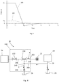
- Figure 6 is a graph showing in a simplified manner how the pressure in the hydraulic lines 204, 206 changes when the selector 230 is moved from the first state to the second state.
- the second supply 28 of hydraulic fluid comprises a pressure limiting valve.
- the line 280 denotes the fluid pressure at the system valve 210 on the side in fluid communication with the selector 230, at point 212 as shown in Figure 5
- the line 285 denotes the fluid pressure at the return line 29 on the side in fluid communication with the second inlet 240, at point 30 in Figure 5
- the line 290 denotes the fluid pressure at the check valve 220 on the side in fluid communication with the selector 230 at point 222, as shown in Figure 5 .
- the fluid pressure at the system valve 210 is the pressure P1 of the hydraulic fluid supplied to the sub-system 200 via the first inlet 202.
- the fluid pressure at the check valve 220 is the return pressure P2 of the sub-system 200, that is, at or about the pressure P2 in the reservoir 26.
- the fluid pressure at the return line 29 is the pressure limiting valve return pressure P3, which is greater than the return pressure P2.
- the selector 230 is moved from the first state or state to the second state or state.
- the fluid pressure at the check valve 220 drops from pressure P2, but does not drop as far as in the system shown in Figures 1-3 .
- the fluid pressure at the return line 29 also drops from pressure P3 as fluid is drawn across the check valve 220.
- the fluid pressure at the system valve 210 drops rapidly from pressure P1 to below zero as hydraulic fluid surges from the system valve 210, along the hydraulic lines 204, 206 connecting the system valve 210 to the check valve 220, and across the check valve 220.
- the pressure at the system valve 210 increases as fluid is drawn from the return line 29 via the second inlet 240 into the hydraulic lines 204, 206.
- the graph of Figure 6 depicts a system in which the second supply 28 of hydraulic fluid comprises a pressure limiting valve
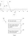
- the graph of Fig 7 depicts a system in which the second supply 28 of hydraulic fluid comprises a hydraulically-operable system of the aircraft hydraulic system 20.
- the pressure in the sub-system 20 is equalised at a faster rate in embodiments of the invention in which the second supply 28 of hydraulic fluid comprises a hydraulically-operable system of the aircraft hydraulic system 20, as compared to embodiments in which the second supply 28 of hydraulic fluid comprises a pressure limiting valve.
- This can be explained by the difference in volume of available pressurised hydraulic fluid in the return line 29, which may be at substantially the same pressure as the pressure in the reservoir 26.
- the second supply 28 of hydraulic fluid comprises a hydraulically-operable system of the aircraft hydraulic system 20
- a greater volume of fluid is available, meaning that fluid is received at the second inlet 240 at a faster rate compared to embodiments in which the second supply 28 of hydraulic fluid comprises a pressure limiting valve.
- Figure 7 is a graph showing a simplified example of how the pressure in the hydraulic lines 204, 206 changes when the isolation valve 230 is moved from the first state to the second position.
- the second supply 28 of hydraulic fluid comprises a hydraulically-operable system of the aircraft hydraulic system 20.
- the line 292 denotes the fluid pressure at the system valve 210, for example at point 212 as shown on Figure 5
- the line 294 denotes the fluid pressure at the return line 29, for example at point 30 as shown on Figure 5
- the line 296 denotes the fluid pressure at the check valve 220, for example at point 222 as shown on Figure 5 .
- the isolation valve 230 is in the first state.
- the fluid pressure at the system valve 210 is the pressure P1 of the hydraulic fluid supplied to the sub-system 200 via the first inlet 202.
- the fluid pressure at the check valve 220 is the return pressure P2 of the sub-system 200, that is, the pressure P2 in the reservoir 26.
- the fluid pressure at the return line 29 is the pressure limiting valve return pressure P3, which is greater than the return pressure P2.
- the isolation valve 230 is moved from the first state to the second position.
- the fluid pressure at the check valve 220 drops from pressure P2, but does not drop as far as in the system shown in Figures 1-3 or as far as in embodiments in which the second supply 28 of hydraulic fluid comprises a pressure limiting valve.
- the fluid pressure at the return line 29 also drops from pressure P3 as fluid is drawn across the check valve 220, does not drop as far as in embodiments in which the second supply 28 of hydraulic fluid comprises a pressure limiting valve.
- the fluid pressure at the system valve 210 drops rapidly from pressure P1 to below zero as hydraulic fluid surges from the system valve 210, along the hydraulic lines 204, 206 connecting the system valve 210 to the check valve 220, and across the check valve 220.
- the pressure at the system valve 210 increases as fluid is drawn from the return line 29 via the second inlet 240 into the hydraulic lines 204, 206.
- the pressure in the system has equalised so that the pressure at the system valve 210 and the check valve 230 has increased to pressure P2 and the pressure at the return line 29 has increased to pressure P3.
- Embodiments of the present invention provide a sub-system for an aircraft hydraulic system.
- the sub-system comprises: an outlet valve configured to selectively permit a flow of hydraulic fluid out of the sub-system, an isolation valve configured to permit a flow of hydraulic fluid to flow to the outlet valve from a supply line when the isolation valve is in a first position, and to isolate the outlet valve from the supply line when the isolation valve is in a second position different from the first position, a non-return valve configured to permit hydraulic fluid to flow from the sub-system and to prevent or hinder hydraulic fluid from flowing into the sub-system, and an inlet line configured to receive a flow of hydraulic fluid in to the sub-system from a supply.
- the isolation valve When the isolation valve is in the first position, the outlet valve is isolated from the non-return valve and the inlet line, and, when the isolation valve is in the second position, the outlet valve is in fluid communication with the non-return valve and the inlet line.
- Embodiments of the present invention comprise a method 300 to help maintain fluid pressure in a sub-system of an aircraft hydraulic system, as shown in Figure 8 .
- the method 300 comprises: closing 310 a system valve, the system valve for controlling fluid flow from the sub-system to a hydraulically-operable system of the aircraft hydraulic system, moving 320 a selector from a first position to a second position, wherein, in the first position, the selector is configured to place the system valve in fluid communication with a first inlet for receiving fluid into the sub-system from a supply of hydraulic fluid, and, in the second position, the selector is configured to place the system valve in fluid communication with a check valve and a second inlet, the check valve for permitting fluid flow from the sub-system and preventing or hindering fluid flow into the sub-system, and receiving 330 a flow of hydraulic fluid into the sub-system via the second inlet from a supply of hydraulic fluid, when the selector is in the second position.
- the sub-system is a sub-system 200 according to the invention
- the method comprises receiving a flow of hydraulic fluid into the sub-system via the second inlet from a return line of the aircraft hydraulic system.
- the return line may be a return line of a pressure limiting valve or a return line of an alternate hydraulically-operated system.
- a pressure of hydraulic fluid received at the first inlet is greater than a pressure of hydraulic fluid received at the second inlet.
- Some embodiments of the present invention comprise an aircraft hydraulic system 20 comprising: a sub-system according to the present invention; a supply 22 of hydraulic fluid to supply hydraulic fluid to the first inlet 202 of the sub-system, a first hydraulically-operable system 24 to receive hydraulic fluid from the sub-system via the system valve 210 when the system valve 210 is open, a second supply 28 of hydraulic fluid to supply hydraulic fluid to the second inlet 240 of the sub-system.
- the second supply 28 of hydraulic fluid comprises a return line of the aircraft hydraulic system 20.
- the second supply 28 of hydraulic fluid may comprise a return line of a pressure limiting valve of the aircraft hydraulic system 20.
- the second supply 28 of hydraulic fluid may comprise a return line of a second hydraulically-operable system of the aircraft hydraulic system 20, different from the first hydraulically-operable system 24.
- the second hydraulically-operable system is a hydraulic system for use in the event that the first hydraulically-operable system 24 fails.
- the first hydraulically-operable system 24 is an aircraft braking system.
- the aircraft comprises one or more main landing gears 510 and a nose landing gear 520, each comprising one or more wheels.
- the aircraft 500 comprises an aircraft hydraulic system comprising a sub-system according to any of the embodiments described herein, for example sub-system 200.
- Some embodiments of the invention provide an aircraft 400 configured to perform a method 300 according to any of the embodiments described herein.
Landscapes
- Engineering & Computer Science (AREA)
- Mechanical Engineering (AREA)
- Physics & Mathematics (AREA)
- Fluid Mechanics (AREA)
- Aviation & Aerospace Engineering (AREA)
- General Engineering & Computer Science (AREA)
- Automation & Control Theory (AREA)
- Chemical & Material Sciences (AREA)
- Analytical Chemistry (AREA)
- Fluid-Pressure Circuits (AREA)
Abstract
Description
- The present invention relates to a sub-system for an aircraft hydraulic system, an aircraft hydraulic system, and a method to help maintain fluid pressure in a sub-system of an aircraft hydraulic system
- An aircraft hydraulic system may comprise one or more sub-systems for operating particular mechanisms of the aircraft, such as an aircraft landing gear, aircraft brakes and flight controls. Such sub-systems may be in use for only a portion of an operational time of the aircraft hydraulic system. In some instances, when a sub-system is not in use, it is isolated from the rest of the aircraft hydraulic system, for example by an isolation valve.
- Isolation of a sub-system can help to reduce or avoid leakage of hydraulic fluid, to protect the system from unrequired operation, for example in a safety critical scenario, and help to reduce the size of components required in the aircraft hydraulic system, thus helping to reduce the overall weight of the aircraft hydraulic system.
- Aircraft hydraulic systems make use of check valves to allow flow of hydraulic fluid over the check valve in a flow direction, and to inhibit or prevent flow of hydraulic fluid over the check valve in an opposite direction to the flow direction. Such check valves help to reduce or prevent excessive leakage of hydraulic fluid from the aircraft hydraulic system and to reduce or prevent back flows that could damage equipment that works only with flow in one direction.
- A first aspect of the present invention provides a sub-system for an aircraft hydraulic system, the sub-system comprising a first inlet for receiving fluid from a supply of hydraulic fluid a system valve for controlling fluid flow from the sub-system to a hydraulically-operable system of the aircraft hydraulic system, a check valve for permitting fluid flow from the sub-system and preventing or hindering fluid flow into the sub-system, a second inlet for receiving fluid from a second supply of hydraulic fluid, and a selector configured to place the system valve in fluid communication with the first inlet when the selector is in a first state, and to place the system valve in fluid communication with the check valve and the second inlet when the selector is in a second state different from the first state.
- Optionally, the second inlet is between the selector and the check valve.
- Optionally, the system valve is a servo valve.
- Optionally, the selector is configured to isolate the system valve from the check valve and the second inlet when the selector is in the first state. Optionally, the selector is configured to isolate the system valve from the first inlet when the selector is in the second state.
- A second aspect of the present invention provides an aircraft hydraulic system comprising a sub-system according to the first aspect of the present invention, a supply of hydraulic fluid to supply hydraulic fluid to the first inlet of the sub-system, a first hydraulically-operable system to receive hydraulic fluid from the sub-system via the system valve when the system valve is open, and a second supply of hydraulic fluid to supply hydraulic fluid to the second inlet of the sub-system.
- Optionally, the second supply of hydraulic fluid comprises a return line of the aircraft hydraulic system.
- Optionally, the second supply of hydraulic fluid comprises a return line of a pressure limiting valve of the aircraft hydraulic system.
- Optionally, the second supply of hydraulic fluid comprises a return line of a second hydraulically-operable system of the aircraft hydraulic system, different from the first hydraulically-operable system. Optionally, the second hydraulically-operable system is a hydraulic system for use in the event that the first hydraulically-operable system fails.
- Optionally, the first hydraulically-operable system is an aircraft braking system.
- A third aspect of the present invention provides a sub-system for an aircraft hydraulic system, the sub-system comprising an outlet valve configured to selectively permit a flow of hydraulic fluid out of the sub-system, an isolation valve configured to permit a flow of hydraulic fluid to flow to the outlet valve from a supply line when the isolation valve is in a first position, and to isolate the outlet valve from the supply line when the isolation valve is in a second position different from the first position, a non-return valve configured to permit hydraulic fluid to flow from the sub-system and to prevent or hinder hydraulic fluid from flowing into the sub-system, and an inlet line configured to receive a flow of hydraulic fluid into the sub-system from a supply, wherein, when the isolation valve is in the first position, the outlet valve is isolated from the non-return valve and the inlet line, and, when the isolation valve is in the second position, the outlet valve is in fluid communication with the non-return valve and the inlet line.
- A fourth aspect of the present invention provides an aircraft comprising a sub-system according to the first aspect or the third aspect of the present invention, or an aircraft hydraulic system according to the second aspect of the present invention.
- A fifth aspect of the present invention provides a method to help maintain fluid pressure in a sub-system of an aircraft hydraulic system, the method comprising closing a system valve, the system valve for controlling fluid flow from the sub-system to a hydraulically-operable system of the aircraft hydraulic system, moving a selector from a first position to a second position, wherein, in the first position, the selector is configured to place the system valve in fluid communication with a first inlet for receiving fluid into the sub-system from a supply of hydraulic fluid, and, in the second position, the selector is configured to place the system valve in fluid communication with a check valve and a second inlet, the check valve for permitting fluid flow from the sub-system and preventing or hindering fluid flow into the sub-system, and receiving hydraulic fluid into the sub-system via the second inlet from a supply of hydraulic fluid, when the selector is in the second position.
- Optionally, the receiving hydraulic fluid comprises receiving hydraulic fluid into the sub-system via the second inlet from a return line of the aircraft hydraulic system.
- Optionally, a pressure of hydraulic fluid received at the first inlet is greater than a pressure of hydraulic fluid received at the second inlet.
- Embodiments of the invention will now be described, by way of example only, with reference to the accompanying drawings, in which:
-
Figure 1 shows a schematic view of a sub-system of an aircraft hydraulic system in an activated state; -
Figure 2 shows a schematic view of the sub-system ofFigure 1 in an isolated state; -
Figure 3 is a graph showing a drop in pressure in the sub-system ofFigure 1 when the sub-system goes from the activated state to the isolated state; -
Figure 4 shows a schematic view of a sub-system of an aircraft hydraulic system in an activated state according to an embodiment of the present invention; -
Figure 5 shows a schematic view of the sub-system ofFigure 4 in an isolated state; -
Figure 6 is a graph showing a drop in pressure in the sub-system ofFigure 4 when the sub-system goes from the activated state to the isolated state; -
Figure 7 is a graph showing a drop in pressure in the sub-system ofFigure 4 when the sub-system goes from the activated state to the isolated state; -
Figure 8 is a flow diagram showing an example of a method according to an embodiment of the present invention; and -
Figure 9 is a schematic front view of an example of an aircraft according to an embodiment of the present invention. - Throughout this application the term "isolation valve" is used to describe a valve configured to isolate a portion of a hydraulic system from another portion of the hydraulic system. The term "isolation valve" is used interchangeably with the term "selector". The term "check valve" is used to describe a valve that permits a flow of fluid in one direction over the valve and prevents or inhibits flow in the opposite direction. The term "check valve" is used interchangeably with the term "non-return valve".
- Sub-systems of aircraft hydraulic systems can be isolated from a supply of hydraulic fluid when the sub-system is not in use. In an open position of an isolation valve, hydraulic fluid is permitted to flow from the supply of hydraulic fluid of the aircraft hydraulic system into the sub-system. In a closed position of the isolation valve, flow of hydraulic fluid from the supply of hydraulic fluid into the sub-system is prevented or significantly restricted.
- In some aircraft hydraulic systems, the isolation of a sub-system of the aircraft hydraulic system can lead to a pressure in the sub-system that is lower than a normal operating pressure of the sub-system. For example, when closure of an isolation valve causes a line downstream of the isolation valve having a sealed end (e.g. defined by a closed valve) to be connected to a return port via a check valve, hydraulic fluid surges across the check valve causing a rapid decrease in the volume of hydraulic fluid in the line. The decrease in volume of hydraulic fluid in the line causes the pressure in the line to fall, which may result in the formation of gas vapour. Such a line will remain in a low pressure state until the isolation valve is opened again and hydraulic fluid is permitted to flow into the line from the hydraulic supply. The sudden increase in line pressure associated with opening of the isolation valve may cause implosion of vapour bubbles, which may damage components of the sub-system such as valves in close proximity to the vapour. Damage to such components may result in failure of the sub-system and/or may reduce the working life of components of the sub-system, thus potentially increasing maintenance and through-life costs of the sub-system.
- The formation of vapour due to rapid pressure decrease in a hydraulic system can be reduced by the installation of an appropriately sized hydraulic accumulator on the line, or by avoiding the hydraulic system having a sealed line when an isolation valve is closed. However, the use of hydraulic accumulators may lead to an increase in system weight, cost and complexity. Hydraulic accumulators would also require additional maintenance activities, such as gas pre-charge check and refill (if required). In some instances, it is not possible to avoid the use of check valves (which result in a sealed line) to avoid the detrimental effects of hydraulic fluid reverse flow from a return network, or to protect the system from pipe ruptures and subsequent hydraulic leakages. The present invention therefore seeks to provide an alternative way to help prevent the formation of vapour in a hydraulic system.
-
Figures 1 and 2 show acomparative sub-system 100 of an aircrafthydraulic system 10. The system comprises afirst inlet 102 for receiving hydraulic fluid from asupply 12 of hydraulic fluid, asystem valve 110 for controlling fluid flow from thesub-system 100 to a hydraulically-operable system 14 of the aircrafthydraulic system 10, acheck valve 120 for permitting fluid flow from thesub-system 100 and preventing or hindering fluid flow into thesub-system 100, and anisolation valve 130 configured to place thesystem valve 110 in fluid communication with thefirst inlet 102 when theisolation valve 130 is in a first position, as shown inFigure 1 , and to place thesystem valve 110 in fluid communication with thecheck valve 120 when theisolation valve 130 is in a second position, as shown inFigure 2. Figures 1 and 2 show that thecheck valve 120 connects thesub-system 100 to areservoir 16 for hydraulic fluid. In other systems, thecheck valve 120 may be connected to other components of the aircrafthydraulic system 10. The pressure of the hydraulic fluid at thefirst inlet 102 is greater than the pressure of hydraulic fluid in thereservoir 16. - As shown in
Figure 1 , when theisolation valve 130 is in the first position, hydraulic fluid is permitted to flow from thesupply 12 of hydraulic fluid to thesystem valve 110 via thefirst inlet 102 in a direction denoted by arrow A. The hydraulic fluid is prevented by theisolation valve 130 from flowing from theisolation valve 130 to thecheck valve 120 along thehydraulic line 104 extending between theisolation valve 130 and thecheck valve 120, as denoted by the dashedhydraulic line 104. - As shown in
Figure 2 , when theisolation valve 130 is in the second position, the hydraulic fluid from thesupply 12 of hydraulic fluid is prevented from entering thesub-system 100 via thefirst inlet 102, as denoted by thedashed line 102. When theisolation valve 130 is in the second position, thesystem valve 110 is placed in fluid communication with thecheck valve 120 so that hydraulic fluid may flow along thehydraulic lines check valve 120 is configured to allow hydraulic fluid to flow along thehydraulic line 104 in a direction C from theisolation valve 130 towards thereservoir 16, and to prevent or hinder hydraulic fluid from flowing in the opposite direction. - When the
isolation valve 130 is moved from the first position to the second position, the volume of hydraulic fluid in thehydraulic lines check valve 120 without any hydraulic fluid entering thehydraulic lines check valve 120 because the pressure in thelines reservoir 16 in the arrangement shown inFigures 1 and 2 ) when theisolation valve 130 is moved from the first position to the second position. In some arrangements, the pressure in thehydraulic lines check valve 130. The drop in pressure can result in the formation of vapour in thehydraulic lines hydraulic line 106 between thesystem valve 110 and theisolation valve 130, more particularly near thesystem valve 110. The speed at which theisolation valve 130 is moved from the first position to the second position may be proportional to the rate of pressure drop in thehydraulic lines hydraulic lines -
Figure 3 is a graph showing in a simplified manner how the pressure in thehydraulic lines isolation valve 130 is moved from the first position to the second position. Thesolid line 180 denotes the fluid pressure at thesystem valve 110 on the side in fluid communication with theisolation valve 130, atpoint 112 inFigure 2 , and the dashedline 190 denotes the fluid pressure at thecheck valve 120 on the side in fluid communication with theisolation valve 130, atpoint 122 inFigure 2 . At time T0, theisolation valve 130 is in the first position. The fluid pressure at thesystem valve 110 is the pressure P1 of the hydraulic fluid supplied to thesub-system 100 via thefirst inlet 102. The fluid pressure at thecheck valve 120 is the return pressure P2 of thesub-system 100, that is, at or about the pressure P2 in thereservoir 16. - At time T1, the
isolation valve 130 is moved from the first position to the second position. In the scenario shown inFigure 3 , the fluid pressure at thecheck valve 120 drops to around zero. In other examples, the fluid pressure P2 at thecheck valve 120 may drop from pressure P2 to a pressure that is greater than zero. In the scenario shown inFigure 3 , the fluid pressure at thesystem valve 110 drops rapidly from pressure P1 to below zero as hydraulic fluid surges from thesystem valve 110, along thehydraulic lines system valve 110 to thecheck valve 120, and across thecheck valve 120. After time T2, the pressure at thesystem valve 110 and thecheck valve 120 substantially equalises and remains constant until theisolation valve 130 is moved from the second position to the first position. This can cause the formation of gas vapour in thehydraulic lines system valve 110 and thecheck valve 120, typically at the highest point in thehydraulic lines -
Figures 4 and5 show asub-system 200 of an aircrafthydraulic system 20 according to an embodiment of the present invention. Thesub-system 200 comprises afirst inlet 202 for receiving fluid from asupply 22 of hydraulic fluid, asystem valve 210 for controlling fluid flow from thesub-system 200 to a hydraulically-operable system 24 of the aircrafthydraulic system 20, acheck valve 220 for permitting fluid flow from thesub-system 200 and preventing or hindering fluid flow into thesub-system 200, asecond inlet 240 for receiving fluid from asecond supply 28 of hydraulic fluid, and aselector 230 configured to place thesystem valve 210 in fluid communication with thefirst inlet 202 when theselector 230 is in a first state, and to place thesystem valve 210 in fluid communication with thecheck valve 220 and thesecond inlet 240 when theselector 230 is in a second state. - Hydraulic fluid received at the
first inlet 202 is at a higher pressure than hydraulic fluid received at thesecond inlet 240. -
Figures 4 and5 show that thecheck valve 220 connects thesub-system 200 to areservoir 26 for hydraulic fluid. In other systems, thecheck valve 220 may be connected to other components of the aircrafthydraulic system 20. In the embodiments shown inFigures 4 and5 , thesecond inlet 240 is between theselector 230 and thecheck valve 220, along thehydraulic line 204. In other embodiments, thesecond inlet 240 may be positioned elsewhere, for example at theselector 230. - In some embodiments, the
system valve 210 is a servo valve, configured to move from an open position to a closed position to selectively control fluid flow from thesub-system 200 to the hydraulically-operable system 24 of the aircrafthydraulic system 20, when theselector 230 is in the first state. In other embodiments, thesystem valve 210 could be other than a servo valve. Any component that acts as a dead end in thehydraulic line 206, for example a second selector, a shuttle valve and an actuator. In a closed position, thesystem valve 210 isolates parts of the aircrafthydraulic system 20 that are upstream of thesystem valve 210 from parts of the aircrafthydraulic system 20 that are downstream of thesystem valve 210. - In some embodiments, the
selector 230 is configured to isolate thesystem valve 210 from thecheck valve 220 and thesecond inlet 240 when theselector 230 is in the first state. In some embodiments, theselector 230 is configured to isolate thesystem valve 210 from thefirst inlet 202 when theselector 230 is in the second state. -
Figure 4 shows thesub-system 200 when theselector 230 is in the first state. Hydraulic fluid is permitted to flow from thesupply 22 of hydraulic fluid along thefirst inlet 202 and to thesystem valve 210 via theselector 230 in a direction denoted by arrow A. The hydraulic fluid is prevented by theselector 230 from flowing from thefirst inlet 202 to thecheck valve 220. Hydraulic fluid is supplied to thehydraulic line 204 extending between theselector 230 and thecheck valve 220 from thesecond inlet 240, and flows through thecheck valve 220 in a direction denoted by arrow C. Thus, the pressure in thehydraulic line 204 is substantially equal to the pressure inhydraulic line 208 connecting thesecond supply 28 of hydraulic fluid to thesecond inlet 240. In some embodiments, thesecond supply 28 comprises a second hydraulically-operable system of the aircrafthydraulic system 20 and thesub-system 200 is configured to receive hydraulic fluid at thesecond inlet 240 from the second hydraulically-operable system. -
Figure 5 shows thesub-system 200 when theselector 230 is in the second state. The hydraulic fluid from thesupply 22 of hydraulic fluid is prevented from entering thesub-system 200 via thefirst inlet 202, as denoted by the dashedline 202. When theselector 230 is in the second state, thesystem valve 210 is placed in fluid communication with thecheck valve 220 and thesecond inlet 240 so that hydraulic fluid may flow along thehydraulic lines check valve 220 is configured to allow hydraulic fluid to flow along thehydraulic line 204 in a direction C from thesecond inlet 240 and across thecheck valve 220, and to prevent or hinder hydraulic fluid from flowing in the opposite direction. - When the
selector 230 is moved from the first state to the second state, the hydraulic fluid in thehydraulic lines check valve 220 because the pressure in thelines reservoir 26 in the examples shown inFigures 4 and5 ) when theselector 230 is moved from the first state to the second state, which could result in the pressure at thesecond inlet 240 being momentarily less than that in thereservoir 26 after thecheck valve 220. However, thehydraulic lines sub-system 200 via thesecond inlet 240, thus restoring the pressure in thehydraulic lines check valve 220. Providing hydraulic fluid to thehydraulic lines second inlet 240 when theselector 230 is in the second state helps to prevent the formation of vapour in thehydraulic lines sub-system 200. - In some embodiments, the hydraulically-
operable system 24 is a brake actuator, and the hydraulically-operable system 24 and thesub-system 200 are comprised in an aircraft braking system of the aircrafthydraulic system 20. Typically, the aircraft braking system is isolated from the aircrafthydraulic system 20 by theselector 230 of thesub-system 200 during flight until commencement of a landing procedure. In other embodiments, the hydraulically-operable system 24 and thesub-system 200 may be comprised in any other hydraulic system of the aircraft hydraulic system. - In some embodiments, as shown in
Figures 4 and5 , thesecond inlet 240 is configured to receive fluid from areturn line 29 of thesecond supply 28. Fluid flows along thereturn line 29 in a direction denoted by arrow F. Asuitable return line 29 has a substantially constant fluid flow and pressure during operation of the aircrafthydraulic system 20 and therefore can reliably provide hydraulic fluid to thesecond inlet 240. Thereturn line 29 originates outside thesub-system 200, and in some embodiments may terminate at thereservoir 26. In embodiments in which thesub-system 200 is comprised in an aircraft braking system, thereturn line 29 may originate in the aircraft braking system, but outside thesub-system 200. - In some embodiments, the
second inlet 240 is configured to receive fluid from areturn line 29 of a pressure limiting valve (not shown) of the aircraft hydraulic system. For example, thesecond supply 28 of hydraulic fluid may comprise a pressure limiting valve. - In some embodiments, the
second inlet 240 is configured to receive fluid from areturn line 29 of a second hydraulically-operable system (not shown) of the aircrafthydraulic system 20. For example, thesecond supply 28 of hydraulic fluid may comprise an alternate hydraulically-operable system comprising thereturn line 29. In some embodiments, the alternate hydraulically-operable system is an alternate hydraulic system for use in the event that the hydraulically-operable system 24 fails. For example, in embodiments wherein the hydraulically-operable system 24 is an aircraft braking system, the alternate hydraulically-operable system may comprise an accumulator configured to operate the brakes in the event that the aircraft braking system fails. A return line of the alternate hydraulically-operable system may be connected to thesecond inlet 240 to provide fluid to thesub-system 200. -
Figure 6 is a graph showing in a simplified manner how the pressure in thehydraulic lines selector 230 is moved from the first state to the second state. In the graph shown inFigure 6 , thesecond supply 28 of hydraulic fluid comprises a pressure limiting valve. Theline 280 denotes the fluid pressure at thesystem valve 210 on the side in fluid communication with theselector 230, atpoint 212 as shown inFigure 5 , theline 285 denotes the fluid pressure at thereturn line 29 on the side in fluid communication with thesecond inlet 240, atpoint 30 inFigure 5 , and theline 290 denotes the fluid pressure at thecheck valve 220 on the side in fluid communication with theselector 230 atpoint 222, as shown inFigure 5 . - At time T0, the
selector 230 is in the first state. The fluid pressure at thesystem valve 210 is the pressure P1 of the hydraulic fluid supplied to thesub-system 200 via thefirst inlet 202. The fluid pressure at thecheck valve 220 is the return pressure P2 of thesub-system 200, that is, at or about the pressure P2 in thereservoir 26. The fluid pressure at thereturn line 29 is the pressure limiting valve return pressure P3, which is greater than the return pressure P2. - At time T1, the
selector 230 is moved from the first state or state to the second state or state. In the example shown inFigure 6 , the fluid pressure at thecheck valve 220 drops from pressure P2, but does not drop as far as in the system shown inFigures 1-3 . The fluid pressure at thereturn line 29 also drops from pressure P3 as fluid is drawn across thecheck valve 220. The fluid pressure at thesystem valve 210 drops rapidly from pressure P1 to below zero as hydraulic fluid surges from thesystem valve 210, along thehydraulic lines system valve 210 to thecheck valve 220, and across thecheck valve 220. After time T2, the pressure at thesystem valve 210 increases as fluid is drawn from thereturn line 29 via thesecond inlet 240 into thehydraulic lines system valve 210 and thecheck valve 230 increases to pressure P2 and the pressure at thereturn line 29 increases to pressure P3 as the pressure in the system equalises. The configuration shown inFigures 4 and5 helps to avoid or lessen the amount of vapour created in thehydraulic line 206 between thesystem valve 210 and theselector 230. - Whereas the graph of
Figure 6 depicts a system in which thesecond supply 28 of hydraulic fluid comprises a pressure limiting valve, the graph ofFig 7 depicts a system in which thesecond supply 28 of hydraulic fluid comprises a hydraulically-operable system of the aircrafthydraulic system 20. As can be seen by comparingFigures 6 and7 , the pressure in thesub-system 20 is equalised at a faster rate in embodiments of the invention in which thesecond supply 28 of hydraulic fluid comprises a hydraulically-operable system of the aircrafthydraulic system 20, as compared to embodiments in which thesecond supply 28 of hydraulic fluid comprises a pressure limiting valve. This can be explained by the difference in volume of available pressurised hydraulic fluid in thereturn line 29, which may be at substantially the same pressure as the pressure in thereservoir 26. In embodiments in which thesecond supply 28 of hydraulic fluid comprises a hydraulically-operable system of the aircrafthydraulic system 20, a greater volume of fluid is available, meaning that fluid is received at thesecond inlet 240 at a faster rate compared to embodiments in which thesecond supply 28 of hydraulic fluid comprises a pressure limiting valve. -
Figure 7 is a graph showing a simplified example of how the pressure in thehydraulic lines isolation valve 230 is moved from the first state to the second position. In the graph shown inFigure 7 , thesecond supply 28 of hydraulic fluid comprises a hydraulically-operable system of the aircrafthydraulic system 20. Theline 292 denotes the fluid pressure at thesystem valve 210, for example atpoint 212 as shown onFigure 5 , theline 294 denotes the fluid pressure at thereturn line 29, for example atpoint 30 as shown onFigure 5 , and theline 296 denotes the fluid pressure at thecheck valve 220, for example atpoint 222 as shown onFigure 5 . - At time T0, the
isolation valve 230 is in the first state. The fluid pressure at thesystem valve 210 is the pressure P1 of the hydraulic fluid supplied to thesub-system 200 via thefirst inlet 202. The fluid pressure at thecheck valve 220 is the return pressure P2 of thesub-system 200, that is, the pressure P2 in thereservoir 26. The fluid pressure at thereturn line 29 is the pressure limiting valve return pressure P3, which is greater than the return pressure P2. - At time T1, the
isolation valve 230 is moved from the first state to the second position. In the example shown inFigure 7 , the fluid pressure at thecheck valve 220 drops from pressure P2, but does not drop as far as in the system shown inFigures 1-3 or as far as in embodiments in which thesecond supply 28 of hydraulic fluid comprises a pressure limiting valve. The fluid pressure at thereturn line 29 also drops from pressure P3 as fluid is drawn across thecheck valve 220, does not drop as far as in embodiments in which thesecond supply 28 of hydraulic fluid comprises a pressure limiting valve. The fluid pressure at thesystem valve 210 drops rapidly from pressure P1 to below zero as hydraulic fluid surges from thesystem valve 210, along thehydraulic lines system valve 210 to thecheck valve 220, and across thecheck valve 220. After time T2, the pressure at thesystem valve 210 increases as fluid is drawn from thereturn line 29 via thesecond inlet 240 into thehydraulic lines system valve 210 and thecheck valve 230 has increased to pressure P2 and the pressure at thereturn line 29 has increased to pressure P3. - Embodiments of the present invention provide a sub-system for an aircraft hydraulic system. The sub-system comprises: an outlet valve configured to selectively permit a flow of hydraulic fluid out of the sub-system, an isolation valve configured to permit a flow of hydraulic fluid to flow to the outlet valve from a supply line when the isolation valve is in a first position, and to isolate the outlet valve from the supply line when the isolation valve is in a second position different from the first position, a non-return valve configured to permit hydraulic fluid to flow from the sub-system and to prevent or hinder hydraulic fluid from flowing into the sub-system, and an inlet line configured to receive a flow of hydraulic fluid in to the sub-system from a supply. When the isolation valve is in the first position, the outlet valve is isolated from the non-return valve and the inlet line, and, when the isolation valve is in the second position, the outlet valve is in fluid communication with the non-return valve and the inlet line.
- Embodiments of the present invention comprise a
method 300 to help maintain fluid pressure in a sub-system of an aircraft hydraulic system, as shown inFigure 8 . Themethod 300 comprises: closing 310 a system valve, the system valve for controlling fluid flow from the sub-system to a hydraulically-operable system of the aircraft hydraulic system, moving 320 a selector from a first position to a second position, wherein, in the first position, the selector is configured to place the system valve in fluid communication with a first inlet for receiving fluid into the sub-system from a supply of hydraulic fluid, and, in the second position, the selector is configured to place the system valve in fluid communication with a check valve and a second inlet, the check valve for permitting fluid flow from the sub-system and preventing or hindering fluid flow into the sub-system, and receiving 330 a flow of hydraulic fluid into the sub-system via the second inlet from a supply of hydraulic fluid, when the selector is in the second position. In some embodiments, the sub-system is a sub-system 200 according to the invention, as described herein. - In some embodiments, the method comprises receiving a flow of hydraulic fluid into the sub-system via the second inlet from a return line of the aircraft hydraulic system. For example, the return line may be a return line of a pressure limiting valve or a return line of an alternate hydraulically-operated system.
- In some embodiments, a pressure of hydraulic fluid received at the first inlet is greater than a pressure of hydraulic fluid received at the second inlet.
- Some embodiments of the present invention comprise an aircraft
hydraulic system 20 comprising: a sub-system according to the present invention; asupply 22 of hydraulic fluid to supply hydraulic fluid to thefirst inlet 202 of the sub-system, a first hydraulically-operable system 24 to receive hydraulic fluid from the sub-system via thesystem valve 210 when thesystem valve 210 is open, asecond supply 28 of hydraulic fluid to supply hydraulic fluid to thesecond inlet 240 of the sub-system. - In some embodiments, the
second supply 28 of hydraulic fluid comprises a return line of the aircrafthydraulic system 20. Thesecond supply 28 of hydraulic fluid may comprise a return line of a pressure limiting valve of the aircrafthydraulic system 20. Thesecond supply 28 of hydraulic fluid may comprise a return line of a second hydraulically-operable system of the aircrafthydraulic system 20, different from the first hydraulically-operable system 24. In some embodiments, the second hydraulically-operable system is a hydraulic system for use in the event that the first hydraulically-operable system 24 fails. - In some embodiments, the first hydraulically-
operable system 24 is an aircraft braking system. - Some embodiments of the present invention provide an
aircraft 400, as shown inFigure 9 . In some embodiments, the aircraft comprises one or moremain landing gears 510 and anose landing gear 520, each comprising one or more wheels. In some embodiments, the aircraft 500 comprises an aircraft hydraulic system comprising a sub-system according to any of the embodiments described herein, forexample sub-system 200. Some embodiments of the invention provide anaircraft 400 configured to perform amethod 300 according to any of the embodiments described herein. - It is to be noted that the term "or" as used herein is to be interpreted to mean "and/or", unless expressly stated otherwise.
- The above embodiments are to be understood as non-limiting illustrative examples of how the present invention, and aspects of the present invention, may be implemented. Further examples of the present invention are envisaged. It is to be understood that any feature described in relation to any one embodiment may be used alone, or in combination with other features described, and may also be used in combination with one or more features of any other of the embodiments, or any combination of any other of the embodiments. Furthermore, equivalents and modifications not described above may also be employed without departing from the scope of the present invention, which is defined in the accompanying claims.
Claims (15)
- A sub-system for an aircraft hydraulic system, the sub-system comprising:a first inlet for receiving fluid from a supply of hydraulic fluid;a system valve for controlling fluid flow from the sub-system to a hydraulically-operable system of the aircraft hydraulic system;a check valve for permitting fluid flow from the sub-system and preventing or hindering fluid flow into the sub-system;a second inlet for receiving fluid from a second supply of hydraulic fluid; anda selector configured to place the system valve in fluid communication with the first inlet when the selector is in a first state, and to place the system valve in fluid communication with the check valve and the second inlet when the selector is in a second state different from the first state.
- The sub-system according to claim 1, wherein the second inlet is between the selector and the check valve.
- The sub-system according claim 1 or claim 2, wherein the system valve is a servo valve.
- The sub-system according to any one of the preceding claims, wherein the selector is configured to isolate the system valve from the check valve and the second inlet when the selector is in the first state.
- The sub-system according to any one of the preceding claims, wherein the selector is configured to isolate the system valve from the first inlet when the selector is in the second state.
- An aircraft hydraulic system, comprising:the sub-system according to any one of claims 1 to 5;a supply of hydraulic fluid to supply hydraulic fluid to the first inlet of the sub-system;a first hydraulically-operable system to receive hydraulic fluid from the sub-system via the system valve when the system valve is open; anda second supply of hydraulic fluid to supply hydraulic fluid to the second inlet of the sub-system.
- The aircraft hydraulic system according to claim 6, wherein the second supply of hydraulic fluid comprises a return line of the aircraft hydraulic system.
- The aircraft hydraulic system according to claim 7, wherein the second supply of hydraulic fluid comprises a return line of a pressure limiting valve of the aircraft hydraulic system.
- The aircraft hydraulic system according to claim 7, wherein the second supply of hydraulic fluid comprises a return line of a second hydraulically-operable system of the aircraft hydraulic system, different from the first hydraulically-operable system,
optionally wherein the second hydraulically-operable system is a hydraulic system for use in the event that the first hydraulically-operable system fails. - The aircraft hydraulic system according to any one of claims 6 to 9, wherein the first hydraulically-operable system is an aircraft braking system.
- A sub-system for an aircraft hydraulic system, the sub-system comprising:an outlet valve configured to selectively permit a flow of hydraulic fluid out of the sub-system;an isolation valve configured to permit a flow of hydraulic fluid to flow to the outlet valve from a supply line when the isolation valve is in a first position, and to isolate the outlet valve from the supply line when the isolation valve is in a second position different from the first position;a non-return valve configured to permit hydraulic fluid to flow from the sub-system and to prevent or hinder hydraulic fluid from flowing into the sub-system; andan inlet line configured to receive a flow of hydraulic fluid into the sub-system from a supply,wherein, when the isolation valve is in the first position, the outlet valve is isolated from the non-return valve and the inlet line, and, when the isolation valve is in the second position, the outlet valve is in fluid communication with the non-return valve and the inlet line.
- An aircraft comprising a sub-system according to any one of claims 1 to 5 or 11 or an aircraft hydraulic system according to any one of claims 6 to 10.
- A method to help maintain fluid pressure in a sub-system of an aircraft hydraulic system, the method comprising:closing a system valve, the system valve for controlling fluid flow from the sub-system to a hydraulically-operable system of the aircraft hydraulic system;moving a selector from a first position to a second position, wherein, in the first position, the selector is configured to place the system valve in fluid communication with a first inlet for receiving fluid into the sub-system from a supply of hydraulic fluid, and, in the second position, the selector is configured to place the system valve in fluid communication with a check valve and a second inlet, the check valve for permitting fluid flow from the sub-system and preventing or hindering fluid flow into the sub-system; andreceiving hydraulic fluid into the sub-system via the second inlet from a supply of hydraulic fluid, when the selector is in the second position.
- The method according to claim 13, wherein the receiving hydraulic fluid comprises receiving hydraulic fluid into the sub-system via the second inlet from a return line of the aircraft hydraulic system.
- The method according to claim 13 or claim 14, wherein a pressure of hydraulic fluid received at the first inlet is greater than a pressure of hydraulic fluid received at the second inlet.
Applications Claiming Priority (1)
| Application Number | Priority Date | Filing Date | Title |
|---|---|---|---|
| GB1801429.0A GB2570500B (en) | 2018-01-29 | 2018-01-29 | Aircraft hydraulic system |
Publications (2)
| Publication Number | Publication Date |
|---|---|
| EP3517432A1 true EP3517432A1 (en) | 2019-07-31 |
| EP3517432B1 EP3517432B1 (en) | 2022-08-10 |
Family
ID=61558039
Family Applications (1)
| Application Number | Title | Priority Date | Filing Date |
|---|---|---|---|
| EP19154061.6A Active EP3517432B1 (en) | 2018-01-29 | 2019-01-28 | Aircraft hydraulic system |
Country Status (4)
| Country | Link |
|---|---|
| US (1) | US11021237B2 (en) |
| EP (1) | EP3517432B1 (en) |
| CN (1) | CN110094375A (en) |
| GB (1) | GB2570500B (en) |
Families Citing this family (3)
| Publication number | Priority date | Publication date | Assignee | Title |
|---|---|---|---|---|
| CN114616176B (en) * | 2019-10-15 | 2025-02-18 | 空中客车营运有限公司 | Method for removing hydraulic fluid from an aircraft hydraulic system, aircraft hydraulic system and aircraft |
| GB2623810A (en) * | 2022-10-28 | 2024-05-01 | Airbus Operations Ltd | Improvements in hydraulic systems |
| GB2625243A (en) * | 2022-10-28 | 2024-06-19 | Airbus Operations Ltd | Hydraulic systems |
Citations (3)
| Publication number | Priority date | Publication date | Assignee | Title |
|---|---|---|---|---|
| EP1218241A1 (en) * | 1999-10-07 | 2002-07-03 | Honeywell Normalair-Garrett (Holdings) Limited | Hydraulic system for aircraft landing gear |
| EP3165455A1 (en) * | 2015-11-09 | 2017-05-10 | Airbus Operations Limited | Cooling of a motor for driving an aircraft wheel |
| WO2017125108A1 (en) * | 2016-01-19 | 2017-07-27 | Schaeffler Technologies AG & Co. KG | Hydraulic switching assembly for a motor vehicle |
Family Cites Families (15)
| Publication number | Priority date | Publication date | Assignee | Title |
|---|---|---|---|---|
| GB8625604D0 (en) * | 1986-10-25 | 1986-11-26 | Dunlop Ltd | Hydraulic systems |
| FR2684066B1 (en) * | 1991-11-26 | 1994-01-07 | Messier Bugatti | ACTUATOR ACTUATION SYSTEM FOR AN AIRCRAFT LANDING GEAR. |
| US5351601A (en) * | 1992-05-04 | 1994-10-04 | Control Concepts, Inc. | Hydraulic control system |
| JP3382981B2 (en) * | 1992-11-12 | 2003-03-04 | 帝人製機株式会社 | Control device of control surface |
| JP2002039117A (en) * | 2000-07-19 | 2002-02-06 | Hitachi Constr Mach Co Ltd | Hydraulic circuit device |
| FR2827346B1 (en) * | 2001-07-12 | 2003-12-26 | Messier Bugatti | HYDRAULIC CIRCUIT ARCHITECTURE |
| CN202659634U (en) * | 2012-06-14 | 2013-01-09 | 武桥重工集团股份有限公司 | Return oil backpressure loop for lowly placed hydraulic system of oil tank |
| US9169001B2 (en) * | 2012-06-29 | 2015-10-27 | Eaton Corporation | Zonal hydraulic systems and methods |
| US10106248B2 (en) * | 2013-06-14 | 2018-10-23 | Bombardier Inc. | Apparatus and method for controlling landing gear |
| CN105745380B (en) * | 2013-11-12 | 2019-06-11 | 克拉克设备公司 | hydraulic brake |
| GB2528321A (en) * | 2014-07-18 | 2016-01-20 | Airbus Operations Ltd | Determining integrity of braking control system |
| CN104632746B (en) * | 2015-03-04 | 2017-11-24 | 徐州重型机械有限公司 | switching valve, switching hydraulic system and crane |
| CN205689746U (en) * | 2016-05-20 | 2016-11-16 | 卡特彼勒(青州)有限公司 | Hydraulic control system and the machine including this hydraulic control system for variator |
| US10273962B2 (en) * | 2016-09-26 | 2019-04-30 | Caterpillar Inc. | System for selectively bypassing fluid supply to one or more operational systems of a machine |
| GB2562781A (en) * | 2017-05-25 | 2018-11-28 | Airbus Operations Ltd | Landing gear bogie pitch trimmer |
-
2018
- 2018-01-29 GB GB1801429.0A patent/GB2570500B/en not_active Expired - Fee Related
-
2019
- 2019-01-25 CN CN201910073356.0A patent/CN110094375A/en active Pending
- 2019-01-28 EP EP19154061.6A patent/EP3517432B1/en active Active
- 2019-01-28 US US16/259,186 patent/US11021237B2/en active Active
Patent Citations (3)
| Publication number | Priority date | Publication date | Assignee | Title |
|---|---|---|---|---|
| EP1218241A1 (en) * | 1999-10-07 | 2002-07-03 | Honeywell Normalair-Garrett (Holdings) Limited | Hydraulic system for aircraft landing gear |
| EP3165455A1 (en) * | 2015-11-09 | 2017-05-10 | Airbus Operations Limited | Cooling of a motor for driving an aircraft wheel |
| WO2017125108A1 (en) * | 2016-01-19 | 2017-07-27 | Schaeffler Technologies AG & Co. KG | Hydraulic switching assembly for a motor vehicle |
Also Published As
| Publication number | Publication date |
|---|---|
| GB201801429D0 (en) | 2018-03-14 |
| GB2570500A (en) | 2019-07-31 |
| GB2570500B (en) | 2020-04-22 |
| US20190233086A1 (en) | 2019-08-01 |
| CN110094375A (en) | 2019-08-06 |
| US11021237B2 (en) | 2021-06-01 |
| EP3517432B1 (en) | 2022-08-10 |
Similar Documents
| Publication | Publication Date | Title |
|---|---|---|
| US11021237B2 (en) | Aircraft hydraulic system | |
| US9238975B2 (en) | Lubricating device having a bypass valve | |
| US8998348B2 (en) | Hydraulic brake architectures for aircrafts for braking at least one wheel of the aircraft | |
| US9709052B1 (en) | Subsea fluid pressure regulation systems and methods | |
| US7337761B2 (en) | Fuel system | |
| US20220341429A1 (en) | Mechanical barrier fluid pressure regulation for subsea systems | |
| US20080035215A1 (en) | Hydraulic System Safety Shut Off Valve | |
| US7565793B2 (en) | Gas turbine engine fuel control system having start / back up check valve (SBUC) providing a main fuel check valve function | |
| JP2013127317A (en) | Flow controlled actuator apparatus for use with self-closing stop valve | |
| US9915372B2 (en) | High integrity pressure protecting system (HIPPS) for a fluid line | |
| EP3505775A1 (en) | Hydraulic no-back device | |
| US9896223B2 (en) | Pump systems for controlling pressure loads | |
| CN108217376B (en) | A kind of proportional pressure control valve perseverance deceleration safety arrestment redundant hydraulic station and its control method | |
| CN108249339B (en) | A kind of perseverance deceleration safety arrestment redundant hydraulic station and its control method | |
| CN103201508B (en) | Brake unit for the hydraulic pressure of wind energy plant | |
| US9409652B2 (en) | Dual pressure regulation system for aerial refueling operations | |
| US12344205B2 (en) | Hydraulic systems | |
| CN216844159U (en) | Pressure regulating system | |
| US10001222B2 (en) | Pressure relief module | |
| CN114562489B (en) | Hydraulic control system for emergency power source and control method thereof | |
| CN112875456B (en) | Self-adaptive buffer hydraulic speed-limiting cutting device, system and method | |
| CN103038519B (en) | Sequence valve assembly and the method for sequence of operation valve assembly | |
| US20240002040A1 (en) | Pneumo-Mechanical Landing Gear Deployment System and Method | |
| CN204628140U (en) | Combination brake switch and proporting |
Legal Events
| Date | Code | Title | Description |
|---|---|---|---|
| PUAI | Public reference made under article 153(3) epc to a published international application that has entered the european phase |
Free format text: ORIGINAL CODE: 0009012 |
|
| STAA | Information on the status of an ep patent application or granted ep patent |
Free format text: STATUS: THE APPLICATION HAS BEEN PUBLISHED |
|
| AK | Designated contracting states |
Kind code of ref document: A1 Designated state(s): AL AT BE BG CH CY CZ DE DK EE ES FI FR GB GR HR HU IE IS IT LI LT LU LV MC MK MT NL NO PL PT RO RS SE SI SK SM TR |
|
| AX | Request for extension of the european patent |
Extension state: BA ME |
|
| STAA | Information on the status of an ep patent application or granted ep patent |
Free format text: STATUS: REQUEST FOR EXAMINATION WAS MADE |
|
| 17P | Request for examination filed |
Effective date: 20200131 |
|
| RBV | Designated contracting states (corrected) |
Designated state(s): AL AT BE BG CH CY CZ DE DK EE ES FI FR GB GR HR HU IE IS IT LI LT LU LV MC MK MT NL NO PL PT RO RS SE SI SK SM TR |
|
| STAA | Information on the status of an ep patent application or granted ep patent |
Free format text: STATUS: EXAMINATION IS IN PROGRESS |
|
| 17Q | First examination report despatched |
Effective date: 20201223 |
|
| GRAP | Despatch of communication of intention to grant a patent |
Free format text: ORIGINAL CODE: EPIDOSNIGR1 |
|
| STAA | Information on the status of an ep patent application or granted ep patent |
Free format text: STATUS: GRANT OF PATENT IS INTENDED |
|
| INTG | Intention to grant announced |
Effective date: 20220221 |
|
| GRAS | Grant fee paid |
Free format text: ORIGINAL CODE: EPIDOSNIGR3 |
|
| GRAA | (expected) grant |
Free format text: ORIGINAL CODE: 0009210 |
|
| STAA | Information on the status of an ep patent application or granted ep patent |
Free format text: STATUS: THE PATENT HAS BEEN GRANTED |
|
| AK | Designated contracting states |
Kind code of ref document: B1 Designated state(s): AL AT BE BG CH CY CZ DE DK EE ES FI FR GB GR HR HU IE IS IT LI LT LU LV MC MK MT NL NO PL PT RO RS SE SI SK SM TR |
|
| REG | Reference to a national code |
Ref country code: AT Ref legal event code: REF Ref document number: 1510371 Country of ref document: AT Kind code of ref document: T Effective date: 20220815 Ref country code: CH Ref legal event code: EP |
|
| REG | Reference to a national code |
Ref country code: IE Ref legal event code: FG4D |
|
| REG | Reference to a national code |
Ref country code: DE Ref legal event code: R096 Ref document number: 602019017942 Country of ref document: DE |
|
| RBV | Designated contracting states (corrected) |
Designated state(s): AL AT BE BG CH CY CZ DE DK EE ES FI FR GR HR HU IE IS IT LI LT LU LV MC MK MT NL NO PL PT RO RS SE SI SK SM TR |
|
| RBV | Designated contracting states (corrected) |
Designated state(s): AL AT BE BG CH CY CZ DE DK EE ES FI FR GB GR HR HU IE IS IT LI LT LU LV MC MK MT NL NO PL PT RO RS SE SI SK SM TR |
|
| REG | Reference to a national code |
Ref country code: NL Ref legal event code: MP Effective date: 20220810 |
|
| REG | Reference to a national code |
Ref country code: LT Ref legal event code: MG9D |
|
| PG25 | Lapsed in a contracting state [announced via postgrant information from national office to epo] |
Ref country code: SE Free format text: LAPSE BECAUSE OF FAILURE TO SUBMIT A TRANSLATION OF THE DESCRIPTION OR TO PAY THE FEE WITHIN THE PRESCRIBED TIME-LIMIT Effective date: 20220810 Ref country code: RS Free format text: LAPSE BECAUSE OF FAILURE TO SUBMIT A TRANSLATION OF THE DESCRIPTION OR TO PAY THE FEE WITHIN THE PRESCRIBED TIME-LIMIT Effective date: 20220810 Ref country code: PT Free format text: LAPSE BECAUSE OF FAILURE TO SUBMIT A TRANSLATION OF THE DESCRIPTION OR TO PAY THE FEE WITHIN THE PRESCRIBED TIME-LIMIT Effective date: 20221212 Ref country code: NO Free format text: LAPSE BECAUSE OF FAILURE TO SUBMIT A TRANSLATION OF THE DESCRIPTION OR TO PAY THE FEE WITHIN THE PRESCRIBED TIME-LIMIT Effective date: 20221110 Ref country code: NL Free format text: LAPSE BECAUSE OF FAILURE TO SUBMIT A TRANSLATION OF THE DESCRIPTION OR TO PAY THE FEE WITHIN THE PRESCRIBED TIME-LIMIT Effective date: 20220810 Ref country code: LV Free format text: LAPSE BECAUSE OF FAILURE TO SUBMIT A TRANSLATION OF THE DESCRIPTION OR TO PAY THE FEE WITHIN THE PRESCRIBED TIME-LIMIT Effective date: 20220810 Ref country code: LT Free format text: LAPSE BECAUSE OF FAILURE TO SUBMIT A TRANSLATION OF THE DESCRIPTION OR TO PAY THE FEE WITHIN THE PRESCRIBED TIME-LIMIT Effective date: 20220810 Ref country code: FI Free format text: LAPSE BECAUSE OF FAILURE TO SUBMIT A TRANSLATION OF THE DESCRIPTION OR TO PAY THE FEE WITHIN THE PRESCRIBED TIME-LIMIT Effective date: 20220810 |
|
| REG | Reference to a national code |
Ref country code: AT Ref legal event code: MK05 Ref document number: 1510371 Country of ref document: AT Kind code of ref document: T Effective date: 20220810 |
|
| PG25 | Lapsed in a contracting state [announced via postgrant information from national office to epo] |
Ref country code: PL Free format text: LAPSE BECAUSE OF FAILURE TO SUBMIT A TRANSLATION OF THE DESCRIPTION OR TO PAY THE FEE WITHIN THE PRESCRIBED TIME-LIMIT Effective date: 20220810 Ref country code: IS Free format text: LAPSE BECAUSE OF FAILURE TO SUBMIT A TRANSLATION OF THE DESCRIPTION OR TO PAY THE FEE WITHIN THE PRESCRIBED TIME-LIMIT Effective date: 20221210 Ref country code: HR Free format text: LAPSE BECAUSE OF FAILURE TO SUBMIT A TRANSLATION OF THE DESCRIPTION OR TO PAY THE FEE WITHIN THE PRESCRIBED TIME-LIMIT Effective date: 20220810 Ref country code: GR Free format text: LAPSE BECAUSE OF FAILURE TO SUBMIT A TRANSLATION OF THE DESCRIPTION OR TO PAY THE FEE WITHIN THE PRESCRIBED TIME-LIMIT Effective date: 20221111 |
|
| PG25 | Lapsed in a contracting state [announced via postgrant information from national office to epo] |
Ref country code: SM Free format text: LAPSE BECAUSE OF FAILURE TO SUBMIT A TRANSLATION OF THE DESCRIPTION OR TO PAY THE FEE WITHIN THE PRESCRIBED TIME-LIMIT Effective date: 20220810 Ref country code: RO Free format text: LAPSE BECAUSE OF FAILURE TO SUBMIT A TRANSLATION OF THE DESCRIPTION OR TO PAY THE FEE WITHIN THE PRESCRIBED TIME-LIMIT Effective date: 20220810 Ref country code: ES Free format text: LAPSE BECAUSE OF FAILURE TO SUBMIT A TRANSLATION OF THE DESCRIPTION OR TO PAY THE FEE WITHIN THE PRESCRIBED TIME-LIMIT Effective date: 20220810 Ref country code: DK Free format text: LAPSE BECAUSE OF FAILURE TO SUBMIT A TRANSLATION OF THE DESCRIPTION OR TO PAY THE FEE WITHIN THE PRESCRIBED TIME-LIMIT Effective date: 20220810 Ref country code: CZ Free format text: LAPSE BECAUSE OF FAILURE TO SUBMIT A TRANSLATION OF THE DESCRIPTION OR TO PAY THE FEE WITHIN THE PRESCRIBED TIME-LIMIT Effective date: 20220810 Ref country code: AT Free format text: LAPSE BECAUSE OF FAILURE TO SUBMIT A TRANSLATION OF THE DESCRIPTION OR TO PAY THE FEE WITHIN THE PRESCRIBED TIME-LIMIT Effective date: 20220810 |
|
| REG | Reference to a national code |
Ref country code: DE Ref legal event code: R097 Ref document number: 602019017942 Country of ref document: DE |
|
| PG25 | Lapsed in a contracting state [announced via postgrant information from national office to epo] |
Ref country code: SK Free format text: LAPSE BECAUSE OF FAILURE TO SUBMIT A TRANSLATION OF THE DESCRIPTION OR TO PAY THE FEE WITHIN THE PRESCRIBED TIME-LIMIT Effective date: 20220810 Ref country code: EE Free format text: LAPSE BECAUSE OF FAILURE TO SUBMIT A TRANSLATION OF THE DESCRIPTION OR TO PAY THE FEE WITHIN THE PRESCRIBED TIME-LIMIT Effective date: 20220810 |
|
| PGFP | Annual fee paid to national office [announced via postgrant information from national office to epo] |
Ref country code: GB Payment date: 20230119 Year of fee payment: 5 |
|
| PLBE | No opposition filed within time limit |
Free format text: ORIGINAL CODE: 0009261 |
|
| STAA | Information on the status of an ep patent application or granted ep patent |
Free format text: STATUS: NO OPPOSITION FILED WITHIN TIME LIMIT |
|
| PG25 | Lapsed in a contracting state [announced via postgrant information from national office to epo] |
Ref country code: AL Free format text: LAPSE BECAUSE OF FAILURE TO SUBMIT A TRANSLATION OF THE DESCRIPTION OR TO PAY THE FEE WITHIN THE PRESCRIBED TIME-LIMIT Effective date: 20220810 |
|
| 26N | No opposition filed |
Effective date: 20230511 |
|
| PG25 | Lapsed in a contracting state [announced via postgrant information from national office to epo] |
Ref country code: SI Free format text: LAPSE BECAUSE OF FAILURE TO SUBMIT A TRANSLATION OF THE DESCRIPTION OR TO PAY THE FEE WITHIN THE PRESCRIBED TIME-LIMIT Effective date: 20220810 |
|
| REG | Reference to a national code |
Ref country code: CH Ref legal event code: PL |
|
| PG25 | Lapsed in a contracting state [announced via postgrant information from national office to epo] |
Ref country code: LU Free format text: LAPSE BECAUSE OF NON-PAYMENT OF DUE FEES Effective date: 20230128 |
|
| REG | Reference to a national code |
Ref country code: BE Ref legal event code: MM Effective date: 20230131 |
|
| PG25 | Lapsed in a contracting state [announced via postgrant information from national office to epo] |
Ref country code: LI Free format text: LAPSE BECAUSE OF NON-PAYMENT OF DUE FEES Effective date: 20230131 Ref country code: CH Free format text: LAPSE BECAUSE OF NON-PAYMENT OF DUE FEES Effective date: 20230131 |
|
| PG25 | Lapsed in a contracting state [announced via postgrant information from national office to epo] |
Ref country code: BE Free format text: LAPSE BECAUSE OF NON-PAYMENT OF DUE FEES Effective date: 20230131 |
|
| PG25 | Lapsed in a contracting state [announced via postgrant information from national office to epo] |
Ref country code: IE Free format text: LAPSE BECAUSE OF NON-PAYMENT OF DUE FEES Effective date: 20230128 |
|
| PGFP | Annual fee paid to national office [announced via postgrant information from national office to epo] |
Ref country code: DE Payment date: 20240119 Year of fee payment: 6 |
|
| PG25 | Lapsed in a contracting state [announced via postgrant information from national office to epo] |
Ref country code: IT Free format text: LAPSE BECAUSE OF FAILURE TO SUBMIT A TRANSLATION OF THE DESCRIPTION OR TO PAY THE FEE WITHIN THE PRESCRIBED TIME-LIMIT Effective date: 20220810 |
|
| PGFP | Annual fee paid to national office [announced via postgrant information from national office to epo] |
Ref country code: FR Payment date: 20240122 Year of fee payment: 6 |
|
| PG25 | Lapsed in a contracting state [announced via postgrant information from national office to epo] |
Ref country code: MC Free format text: LAPSE BECAUSE OF FAILURE TO SUBMIT A TRANSLATION OF THE DESCRIPTION OR TO PAY THE FEE WITHIN THE PRESCRIBED TIME-LIMIT Effective date: 20220810 |
|
| PG25 | Lapsed in a contracting state [announced via postgrant information from national office to epo] |
Ref country code: MC Free format text: LAPSE BECAUSE OF FAILURE TO SUBMIT A TRANSLATION OF THE DESCRIPTION OR TO PAY THE FEE WITHIN THE PRESCRIBED TIME-LIMIT Effective date: 20220810 |
|
| GBPC | Gb: european patent ceased through non-payment of renewal fee |
Effective date: 20240128 |
|
| PG25 | Lapsed in a contracting state [announced via postgrant information from national office to epo] |
Ref country code: GB Free format text: LAPSE BECAUSE OF NON-PAYMENT OF DUE FEES Effective date: 20240128 |
|
| PG25 | Lapsed in a contracting state [announced via postgrant information from national office to epo] |
Ref country code: GB Free format text: LAPSE BECAUSE OF NON-PAYMENT OF DUE FEES Effective date: 20240128 |
|
| PG25 | Lapsed in a contracting state [announced via postgrant information from national office to epo] |
Ref country code: BG Free format text: LAPSE BECAUSE OF FAILURE TO SUBMIT A TRANSLATION OF THE DESCRIPTION OR TO PAY THE FEE WITHIN THE PRESCRIBED TIME-LIMIT Effective date: 20220810 |
|
| PG25 | Lapsed in a contracting state [announced via postgrant information from national office to epo] |
Ref country code: BG Free format text: LAPSE BECAUSE OF FAILURE TO SUBMIT A TRANSLATION OF THE DESCRIPTION OR TO PAY THE FEE WITHIN THE PRESCRIBED TIME-LIMIT Effective date: 20220810 |
|
| PG25 | Lapsed in a contracting state [announced via postgrant information from national office to epo] |
Ref country code: CY Free format text: LAPSE BECAUSE OF FAILURE TO SUBMIT A TRANSLATION OF THE DESCRIPTION OR TO PAY THE FEE WITHIN THE PRESCRIBED TIME-LIMIT; INVALID AB INITIO Effective date: 20190128 |
|
| REG | Reference to a national code |
Ref country code: DE Ref legal event code: R119 Ref document number: 602019017942 Country of ref document: DE |
|
| PG25 | Lapsed in a contracting state [announced via postgrant information from national office to epo] |
Ref country code: HU Free format text: LAPSE BECAUSE OF FAILURE TO SUBMIT A TRANSLATION OF THE DESCRIPTION OR TO PAY THE FEE WITHIN THE PRESCRIBED TIME-LIMIT; INVALID AB INITIO Effective date: 20190128 |
|
| PG25 | Lapsed in a contracting state [announced via postgrant information from national office to epo] |
Ref country code: DE Free format text: LAPSE BECAUSE OF NON-PAYMENT OF DUE FEES Effective date: 20250801 |
|
| PG25 | Lapsed in a contracting state [announced via postgrant information from national office to epo] |
Ref country code: FR Free format text: LAPSE BECAUSE OF NON-PAYMENT OF DUE FEES Effective date: 20250131 |
|
| PG25 | Lapsed in a contracting state [announced via postgrant information from national office to epo] |
Ref country code: TR Free format text: LAPSE BECAUSE OF FAILURE TO SUBMIT A TRANSLATION OF THE DESCRIPTION OR TO PAY THE FEE WITHIN THE PRESCRIBED TIME-LIMIT Effective date: 20220810 |