EP3517358B1 - Vehicle seat - Google Patents
Vehicle seat Download PDFInfo
- Publication number
- EP3517358B1 EP3517358B1 EP17853104.2A EP17853104A EP3517358B1 EP 3517358 B1 EP3517358 B1 EP 3517358B1 EP 17853104 A EP17853104 A EP 17853104A EP 3517358 B1 EP3517358 B1 EP 3517358B1
- Authority
- EP
- European Patent Office
- Prior art keywords
- frame
- edge frame
- seat
- vehicle seat
- cushion
- Prior art date
- Legal status (The legal status is an assumption and is not a legal conclusion. Google has not performed a legal analysis and makes no representation as to the accuracy of the status listed.)
- Not-in-force
Links
Images



Classifications
-
- B—PERFORMING OPERATIONS; TRANSPORTING
- B60—VEHICLES IN GENERAL
- B60N—SEATS SPECIALLY ADAPTED FOR VEHICLES; VEHICLE PASSENGER ACCOMMODATION NOT OTHERWISE PROVIDED FOR
- B60N2/00—Seats specially adapted for vehicles; Arrangement or mounting of seats in vehicles
- B60N2/70—Upholstery springs ; Upholstery
- B60N2/7094—Upholstery springs
-
- B—PERFORMING OPERATIONS; TRANSPORTING
- B60—VEHICLES IN GENERAL
- B60N—SEATS SPECIALLY ADAPTED FOR VEHICLES; VEHICLE PASSENGER ACCOMMODATION NOT OTHERWISE PROVIDED FOR
- B60N2/00—Seats specially adapted for vehicles; Arrangement or mounting of seats in vehicles
- B60N2/24—Seats specially adapted for vehicles; Arrangement or mounting of seats in vehicles for particular purposes or particular vehicles
- B60N2/32—Seats specially adapted for vehicles; Arrangement or mounting of seats in vehicles for particular purposes or particular vehicles convertible for other use
- B60N2/36—Seats specially adapted for vehicles; Arrangement or mounting of seats in vehicles for particular purposes or particular vehicles convertible for other use into a loading platform
-
- B—PERFORMING OPERATIONS; TRANSPORTING
- B60—VEHICLES IN GENERAL
- B60N—SEATS SPECIALLY ADAPTED FOR VEHICLES; VEHICLE PASSENGER ACCOMMODATION NOT OTHERWISE PROVIDED FOR
- B60N2/00—Seats specially adapted for vehicles; Arrangement or mounting of seats in vehicles
- B60N2/005—Arrangement or mounting of seats in vehicles, e.g. dismountable auxiliary seats
- B60N2/015—Attaching seats directly to vehicle chassis
-
- B—PERFORMING OPERATIONS; TRANSPORTING
- B60—VEHICLES IN GENERAL
- B60N—SEATS SPECIALLY ADAPTED FOR VEHICLES; VEHICLE PASSENGER ACCOMMODATION NOT OTHERWISE PROVIDED FOR
- B60N2/00—Seats specially adapted for vehicles; Arrangement or mounting of seats in vehicles
- B60N2/68—Seat frames
-
- B—PERFORMING OPERATIONS; TRANSPORTING
- B60—VEHICLES IN GENERAL
- B60N—SEATS SPECIALLY ADAPTED FOR VEHICLES; VEHICLE PASSENGER ACCOMMODATION NOT OTHERWISE PROVIDED FOR
- B60N2/00—Seats specially adapted for vehicles; Arrangement or mounting of seats in vehicles
- B60N2/68—Seat frames
- B60N2/688—Particular seat belt attachment and guiding
-
- B—PERFORMING OPERATIONS; TRANSPORTING
- B60—VEHICLES IN GENERAL
- B60N—SEATS SPECIALLY ADAPTED FOR VEHICLES; VEHICLE PASSENGER ACCOMMODATION NOT OTHERWISE PROVIDED FOR
- B60N2/00—Seats specially adapted for vehicles; Arrangement or mounting of seats in vehicles
- B60N2/70—Upholstery springs ; Upholstery
- B60N2/72—Attachment or adjustment thereof
-
- A—HUMAN NECESSITIES
- A47—FURNITURE; DOMESTIC ARTICLES OR APPLIANCES; COFFEE MILLS; SPICE MILLS; SUCTION CLEANERS IN GENERAL
- A47C—CHAIRS; SOFAS; BEDS
- A47C7/00—Parts, details, or accessories of chairs or stools
- A47C7/02—Seat parts
- A47C7/28—Seat parts with tensioned springs, e.g. of flat type
- A47C7/32—Seat parts with tensioned springs, e.g. of flat type with tensioned cords, e.g. of elastic type, in a flat plane
-
- B—PERFORMING OPERATIONS; TRANSPORTING
- B60—VEHICLES IN GENERAL
- B60N—SEATS SPECIALLY ADAPTED FOR VEHICLES; VEHICLE PASSENGER ACCOMMODATION NOT OTHERWISE PROVIDED FOR
- B60N2/00—Seats specially adapted for vehicles; Arrangement or mounting of seats in vehicles
- B60N2/24—Seats specially adapted for vehicles; Arrangement or mounting of seats in vehicles for particular purposes or particular vehicles
- B60N2/42—Seats specially adapted for vehicles; Arrangement or mounting of seats in vehicles for particular purposes or particular vehicles the seat constructed to protect the occupant from the effect of abnormal g-forces, e.g. crash or safety seats
-
- B—PERFORMING OPERATIONS; TRANSPORTING
- B60—VEHICLES IN GENERAL
- B60N—SEATS SPECIALLY ADAPTED FOR VEHICLES; VEHICLE PASSENGER ACCOMMODATION NOT OTHERWISE PROVIDED FOR
- B60N2205/00—General mechanical or structural details
- B60N2205/30—Seat or seat parts characterised by comprising plural parts or pieces
- B60N2205/35—Seat, bench or back-rests being split laterally in two or more parts
Definitions
- the present invention relates to a seat for vehicles such as automobiles, in particular, to a vehicle seat suitable as a rear seat.
- Patent Document 1 discloses a vehicle seat suitable as a rear seat.
- plate members made of hard synthetic resin are disposed on a front edge frame of a seat cushion part via leaf springs, and a seat cushion pad made of urethane is disposed on upper portions of the plate members. Since rear edge portions of the plate members are not fixed and only their front edge portions are supported by the aforesaid leaf springs, the rear edge portion sides are elastically biased so as to be displaced in an up-down direction around the front edge portions.
- Patent Document 1 Japanese Patent Application Laid-open No. 2014-108741 (corresponding to WO-2014087870 ).
- vibration absorbency is improved using elastic force by adopting the cantilever structure in which the plate members are supported only on the front edge frame via the leaf springs as described above. Further, since the plate members are made of the synthetic resin harder than the seat cushion pad, load concentration is prevented, resulting also in excellent body pressure dispersibility. However, giving importance to the use of an elastic action, this structure still has room for improvement in a damping characteristic.
- the present invention was made in consideration of the above, and has an object to provide a vehicle seat that can contribute to a further improvement in vibration absorbency and shock absorbency and so on represented by the vibration absorbency, by the balanced functioning of an elastic action and a damping characteristic function.
- the vehicle seat of the present invention is a vehicle seat which includes a seat cushion part and a seat back part, the seat cushion part including:
- the wire members are hard-drawn steel wires or spring steel wires.
- the spring members are coil springs.
- the vehicle seat includes a vehicle body attachment bracket projecting rearward from the rear edge frame of the cushion frame, and force acting on the front edge frame is transmitted to the vehicle body attachment bracket through the pair of side frames.
- the seat back part includes a back frame coupled by the vehicle body attachment bracket, the back frame includes: an outer frame in a substantially quadrangular shape; a trunk support plate extending in the up-down direction in the outer frame and supporting the back of a seated person; and an intersecting frame extending in a vehicle width direction so as to intersect with the trunk support plate and fixed to the trunk support plate at an intersection portion, and the trunk support plate and the intersecting frame are transmission paths of force toward the cushion frame.
- the vehicle seat of the present invention is suitable especially as a rear seat.
- the seat cushion part includes the base fabric extending between and looped around the front edge frame and the rear edge frame, and having the upper layer part and the lower layer part which are provided apart from each other in the up-down direction, the metal wire members are provided along the side edge portions of the lower layer part of the base fabric, and the spring members each extend between the end portion of the wire member and the front edge frame or the rear edge frame. Therefore, when given a load, the upper layer part of the base fabric which is only looped around the front edge frame and the rear edge frame is displaced downward to damp the force. When given a further load due to vibration, shock, and so on, the upper layer part comes into contact with the lower layer part to also displace the lower layer part in the up-down direction.
- the present invention enables the balanced functioning of the damping characteristic accompanying the displacement of the upper layer part of the base fabric and the elastic action of the spring members accompanying the displacement of the lower layer part.
- the spring constant of the spring members reduces, enabling an increase in a damping ratio of the base fabric. Therefore, the vehicle seat of the present invention can exhibit high damping force and can contribute to a further improvement in vibration absorbency and shock absorbency in spite of being thin.
- Adopting the hard-drawn steel wires as the wire members makes it possible to effectively bring out the elastic force of the front and rear spring members coupled to the wire members.
- Adopting the spring steel wires makes it possible to further increase the vibration absorbency and the shock absorbency because the elastic force of the spring steel wires themselves also functions.
- the metal wire members disposed along the side portions of the base fabric makes body pressure dispersibility excellent.
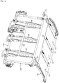
- FIG. 1 to FIGs. 8 illustrate an example where the configuration of the vehicle seat of the present invention is applied to a rear seat 1.
- the rear seat 1 includes a seat cushion part 10 and a seat back part 20.
- the seat cushion part 10 has two side seat parts 11, 12 which are a predetermined interval apart from each other in a vehicle width direction and a center seat part 13 therebetween.
- the seat cushion part 10 includes a cushion frame 100, a seat cushion pad 110, and a seat cushion cover member 120 (refer to FIGs. 8 ).
- the cushion frame 100 includes: a front edge frame 101 and a rear edge frame 102 which extend in the vehicle width direction and are disposed a predetermined interval apart from each other in a front-rear direction; and a pair of side frames 103, 104 which are each disposed between opposed end portions of the front edge frame 101 and the rear edge frame 102 (refer to FIG. 2 to FIG. 5 and so on).
- Three vehicle body attachment brackets 105 projecting rearward are provided on the rear edge frame 102 at appropriate intervals, and the vehicle body attachment brackets 105 are fixed at predetermined positions of the vehicle body with bolts.
- the cushion frame 100 of the seat cushion part 10 has the front edge frame 101, the rear edge frame 102, and the side frames 103, 104 extending between the front edge frame 101 and the rear edge frame 102, and is formed in a substantially quadrangular shape in a plane view. Accordingly, a large impact applied in the front-rear direction is transmitted from the front edge frame 101 to the rear edge frame 102 through the side frames 103, 104, and is further transmitted to the vehicle body through the vehicle body attachment brackets 105.
- This structure eliminates a need for the fixation on the front edge side at a plurality of places as is done in conventional rear seats, and only the fixation at one place near the middle of the front edge frame 101 is enough in order to obtain sufficient strength. Further, even if the seat cushion pad 110 is thinner than conventional ones, impact energy is efficiently dispersed.
- wires 106 which are arranged in the vehicle width direction extend substantially in parallel to the side frames 103, 104. Specifically, two of the wires 106, 106 are disposed right on inner sides of the side frames 103, 104 respectively, and between the two wires 106, 106, the other two wires 106, 106 are arranged in the vehicle width direction at substantially equal intervals, and positions between the adjacent wires 106, 106 correspond to the aforesaid side seat parts 11, 12 and center seat part 13. Incidentally, these wires 106 are used to support the seat cushion cover member 120 in a suspended manner.
- a base fabric 107 is disposed in each space between the adjacent wires 106, 106. That is, the three base fabrics 107 are provided at the aforesaid positions corresponding to the side seat parts 11, 12 and the center seat part 13.
- the base fabrics 107 each extend in the front-rear direction between and looped around the front edge frame 101 and the rear edge frame 102. Accordingly, the base fabrics 107 each have an upper layer part 1071 and a lower layer part 1072 whose vertical interval corresponds to the diameter of the front edge frame 101 and the rear edge frame 102 (refer to FIG. 8(a) ).
- the front edge frame 101 and the rear edge frame 102 themselves are not displaced, and the base fabrics 107 are only looped around the fixed front edge frame 101 and rear edge frame 102 and are not strongly tensed in the looped stated. Therefore, when a downward load is applied to the base fabrics 107, the upper layer parts 1071 act to damp force ascribable to the load by being displaced downward while receiving the force until coming into contact with the lower layer parts 1072.
- the base fabrics 107 preferably extend between the front edge frame 101 and the rear edge frame 102 with an elongation percentage of 5% or less, more preferably with an elongation percentage of 0%, in order to achieve such a function. More preferably, the base fabrics 107 extend with a slight slack.
- wire members 1073, 1073 made of metal extend in the front-rear direction.
- Their installation method may be any and can be, for example, to form the side edge portions 1072a, 1072a in a cylindrical shape and insert the wire members 1073, 1073 into the side edge portions 1072a, 1072a.
- the front-rear-direction length of the cylindrical side edge portions 1072a, 1072a is shorter than the front-rear-direction length of the widthwise center portions of the base fabrics 107, and the side edge portions 1072a, 1072a are in contact with neither the front edge frame 101 nor the rear edge frame 102.
- the wire members 1073, 1073 are coupled to spring members.
- coil springs 108, 109 are used as the spring members as in this embodiment.
- the front coil springs 108 are suspended by their hooks being engaged with engagement portions 101a welded to the front edge frame 101 and with the front end portions 1073a of the wire members 1073
- the rear coil springs 109 are suspended by their hooks being engaged with engagement portions 102a welded to the rear edge frame 102 and with the rear end portions 1073b of the wire members 1073.
- the engagement portions 101a on the front edge frame 101 and the engagement portions 102a on the rear edge frame 102 are all located near extensions of the side edge portions 1072a, 1072a of the base fabrics 107.
- each pair of the coil springs 108, 109 is in series connection through the wire member 1073, so that a spring constant reduces.
- the reduction in the spring constant results in a structure having a high damping ratio to the vibration input to the base fabrics 107 supported by the coil springs 108, 109 and the wire members 1073. Consequently, the base fabrics 107 can exhibit a high damping characteristic even though their up-down stroke is small.
- steel wires are preferably used.
- the use of hard-drawn steel wires or spring steel wires is more preferable.
- the hard-drawn steel wires are substantially linear even when the vibration is input while a person is seated as indicated by the imaginary line in FIG. 8(c) and act to bring out the elasticity of the front and rear coil springs 108, 109 sufficiently.
- the spring steel wires deflect according to the up-down displacement as indicated by the imaginary line in FIG. 8(c) and accordingly the elasticity of the spring steel wires themselves further act and they each constitute part of the series-connection spring element together with the front and rear coil springs 108, 109, making it possible to further increase the damping ratio.
- Whether to use the hard steel wires or the spring steel wires can be selected according to the required feeling of seating and performance.
- wire members 1073, 1073 are provided on the side edge portions 1072a, 1072a in the base fabrics 107, they can also function to reduce load concentration and increase body pressure dispersibility.
- the use of the hard-drawn steel wires leads to increased rigidity, which is more preferable in terms of the body pressure dispersibility.
- the base fabrics 107 two-dimensional fabrics (including any of types such as woven fabrics, nonwoven fabrics, knitted fabrics, and nets) are usable, but the use of three-dimensional fabrics (including any of types such as woven fabrics, nonwoven fabrics, knitted fabrics, and nets) is preferable because the thickness-direction friction between their yarns or fibers can produce higher damping force.
- the use of three-dimensional knitted fabrics in which connecting yarns are repeatedly knitted to/from a pair of ground knitted fabrics is more preferable because friction force between their adjacent connecting yarns easily acts.
- seat cushion pads 110 made of urethane or the like are disposed with their front and rear portions being supported by the front edge frame 101 and the rear edge frame 102 respectively. Their surfaces are covered with the seat cushion cover member 120 (refer to FIGs. 8 ).
- the seat back part 20 is structured such that seat back pads (not illustrated) are supported by the back frame 200 by integrated foam molding or the like and their surfaces are covered with the seat back cover member 220 (refer to FIG. 1 ).
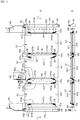
- the back frame 200 can have a structure in which, for example, it is divided in the vehicle width direction at a 6 : 4 ratio and has a first outer frame 201 and a second outer frame 202 which are both formed through the working of pipe materials into a substantially quadrangular shape, as illustrated in FIG. 2 and FIG. 3 .
- the first outer frame 201 has a width equal to the total width of the side seat part 11 and the center seat part 13 of the aforesaid seat cushion part 10, and the second outer frame 202 has a width equivalent to the width of the other side seat part 12.
- Lower portions of side frames 201a, 201b of the first outer frame 201 and lower portions of side frames 202a, 202b of the second outer frame 202 are bolt-connected to the middles of the three vehicle body attachment brackets 105 projecting rearward from the rear edge frame 102 of the cushion frame 100.
- trunk support plates 203, 204 are disposed respectively at a position corresponding to the back (in particular, near the center of the back) of a person seated in the side seat part 11 and at a position corresponding to the back (in particular near the center of the back) of a person seated in the center seat part 13, and extend in the up-down direction between an upper frame 201c and a lower frame 201d of the first outer frame 201.
- a trunk support plate 205 is disposed at a position corresponding to the back (in particular, near the center of the back) of a person seated in the other side seat part 12 and extends in the up-down direction between an upper frame 202c and a lower frame 202d of the second outer frame 202.
- the trunk support plates 203, 204, 205 have a shape whose lower portions bulge more forward than substantially middle portions in terms of the up-down direction, and their middle portions higher than the bulging portions 203a, 204a, 205a, that is, the substantially middle portions in terms of the up-down direction are relatively weak portions.
- the trunk support plates 203, 204, 205 support the backs of the persons during the normal time, and when a large load is applied in such a direction as to push the backs of the persons against the seat back part 20, the whole outer frames 201, 202 incline rearward with the upper sides of the outer frames 201, 202 being displaced rearward.
- the outer frame 201 and the outer frame 202 incline rearward for the purpose of impact absorption.
- This structure makes it possible to efficiently support a load and absorb an impact even without the whole surfaces of the first outer frame 201 and the second outer frame 202 having a panel form.
- the trunk support plates 203, 204, 205 each have a substantially C-shaped (hat-shaped) section. Accordingly, when a load is applied from the rear, in particular, when baggage in a baggage compartment moves forward due to sudden braking and gives a certain load or more, the trunk support plates 203, 204, 205 deform such that their side portions substantially in the C-shape buckle because open surfaces of the sections substantially in the C-shape face rearward. This deformation can absorb impact energy. In addition, if the impact energy has a certain magnitude or more, the trunk support plates 203, 204, 205 deform substantially in a dogleg shape to absorb the impact because the up-down-direction substantially middle portions thereof are relatively weak portions. Therefore, the back frame 200 of this embodiment can efficiently absorb the impact energy applied either from the front or from the rear.
- a reinforcing frame 206 extending in the vehicle width direction is weld-fixed to the trunk support plates 203, 204 of the first outer frame 201 at intersection portions on the substantially middle portions in terms of the up and down direction, specifically, on portions slightly higher than the bulging portions 203a, 204a. Consequently, when energy accompanying an impact is applied to the seat back part 20 even at positions deviated from the trunk support plates 203, 204, not to mention the positions corresponding to these trunk support plates 203, 204, the energy passes through the reinforcing frame 206 and can be transmitted and dispersed to the rear edge frame 102 and the vehicle body attachment brackets 105 of the seat cushion frame 100 via the trunk support plates 203, 204 and the first outer frame 201. This can improve strength and durability.
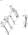
- the back frame 200 may have a structure using an outer frame 2100 formed of one quadrangular frame extending in the vehicle width direction as illustrated in FIG. 4 , instead of the divided type illustrated in FIG. 2 and FIG. 3 .
- the reinforcing frame 206 is preferably provided so as to intersect with all of these.
- energy applied to the seat back part 20 can be transmitted and dispersed to the outer frame 2100 and to the rear edge frame 102 and the vehicle body attachment brackets 105 of the cushion frame 100, through the reinforcing frame 206 and the three trunk support plates 203, 204, 205. This can also improve strength and durability.
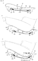
- the state illustrated in FIG. 8(a) changes to the state in FIG. 8(b) .
- the upper layer part 1071 of the base fabric 107 is displaced downward to damp the force.
- the upper layer part 1071 is displaced in the up-down direction as illustrated in FIG. 8(c) .
- the vibration is efficiently eliminated owing to the elastic action of the front and rear coil springs 108, 109 connected in series through the wire members 1073. Further, since the coil springs 108, 109 are connected in series through the wire members 1073, the damping ratio of the base fabric 107 supported by the coil springs 108, 109 is high, and even when large impact energy is applied, high damping force can be exhibited.
- the thickness of a range including these members can be about slightly larger than the diameter of the front edge frame 101 and the rear edge frame 102, and it is possible to exhibit high damping force in spite of the thin structure. Therefore, this structure is preferably used for a rear seat whose lower space is small. However, it is possible to use the structure of this embodiment for a front seat.
Landscapes
- Engineering & Computer Science (AREA)
- Aviation & Aerospace Engineering (AREA)
- Transportation (AREA)
- Mechanical Engineering (AREA)
- Seats For Vehicles (AREA)
Description
- The present invention relates to a seat for vehicles such as automobiles, in particular, to a vehicle seat suitable as a rear seat.
- Patent Document 1 discloses a vehicle seat suitable as a rear seat. In this vehicle seat, plate members made of hard synthetic resin are disposed on a front edge frame of a seat cushion part via leaf springs, and a seat cushion pad made of urethane is disposed on upper portions of the plate members. Since rear edge portions of the plate members are not fixed and only their front edge portions are supported by the aforesaid leaf springs, the rear edge portion sides are elastically biased so as to be displaced in an up-down direction around the front edge portions.
- Patent Document 1: Japanese Patent Application Laid-open No.
2014-108741 WO-2014087870 ). - In the vehicle seat described in Patent Document 1, vibration absorbency is improved using elastic force by adopting the cantilever structure in which the plate members are supported only on the front edge frame via the leaf springs as described above. Further, since the plate members are made of the synthetic resin harder than the seat cushion pad, load concentration is prevented, resulting also in excellent body pressure dispersibility. However, giving importance to the use of an elastic action, this structure still has room for improvement in a damping characteristic.
- The present invention was made in consideration of the above, and has an object to provide a vehicle seat that can contribute to a further improvement in vibration absorbency and shock absorbency and so on represented by the vibration absorbency, by the balanced functioning of an elastic action and a damping characteristic function.
- In order to solve the aforesaid problem, the vehicle seat of the present invention is a vehicle seat which includes a seat cushion part and a seat back part,
the seat cushion part including: - a cushion frame including a front edge frame and a rear edge frame which are arranged a predetermined interval apart from each other in a front-rear direction and a pair of side frames each disposed between opposed longitudinal-direction end portions of the front edge frame and the rear edge frame;
- a base fabric extending between and looped around the front edge frame and the rear edge frame, and having an upper layer part and a lower layer part which are provided apart from each other in an up-down direction;
- wire members of metal extending in the front-rear direction respectively on side edge portions of the lower layer part of the base fabric; and
- spring members extending between the front edge frame and front end portions of the wire members and between the rear edge frame and rear end portions of the wire members.
- Preferably, the wire members are hard-drawn steel wires or spring steel wires. Preferably, the spring members are coil springs.
- Preferably, the vehicle seat includes a vehicle body attachment bracket projecting rearward from the rear edge frame of the cushion frame, and force acting on the front edge frame is transmitted to the vehicle body attachment bracket through the pair of side frames.
- Preferably, the seat back part includes a back frame coupled by the vehicle body attachment bracket, the back frame includes: an outer frame in a substantially quadrangular shape; a trunk support plate extending in the up-down direction in the outer frame and supporting the back of a seated person; and an intersecting frame extending in a vehicle width direction so as to intersect with the trunk support plate and fixed to the trunk support plate at an intersection portion, and the trunk support plate and the intersecting frame are transmission paths of force toward the cushion frame.
- The vehicle seat of the present invention is suitable especially as a rear seat.
- According to the vehicle seat of the present invention, the seat cushion part includes the base fabric extending between and looped around the front edge frame and the rear edge frame, and having the upper layer part and the lower layer part which are provided apart from each other in the up-down direction, the metal wire members are provided along the side edge portions of the lower layer part of the base fabric, and the spring members each extend between the end portion of the wire member and the front edge frame or the rear edge frame. Therefore, when given a load, the upper layer part of the base fabric which is only looped around the front edge frame and the rear edge frame is displaced downward to damp the force. When given a further load due to vibration, shock, and so on, the upper layer part comes into contact with the lower layer part to also displace the lower layer part in the up-down direction. Consequently, the spring members connected through the wire members extend/contract and their elastic force acts. Therefore, the present invention enables the balanced functioning of the damping characteristic accompanying the displacement of the upper layer part of the base fabric and the elastic action of the spring members accompanying the displacement of the lower layer part. In addition, since each pair of the front and rear spring members engaged with the base fabric is in series connection through the metal wire member, the spring constant of the spring members reduces, enabling an increase in a damping ratio of the base fabric. Therefore, the vehicle seat of the present invention can exhibit high damping force and can contribute to a further improvement in vibration absorbency and shock absorbency in spite of being thin. Adopting the hard-drawn steel wires as the wire members makes it possible to effectively bring out the elastic force of the front and rear spring members coupled to the wire members. Adopting the spring steel wires makes it possible to further increase the vibration absorbency and the shock absorbency because the elastic force of the spring steel wires themselves also functions. Further, the metal wire members disposed along the side portions of the base fabric makes body pressure dispersibility excellent.
-
- [
FIG. 1] FIG. 1 is an external perspective view illustrating a rear seat according to one embodiment of the present invention. - [
FIG. 2] FIG. 2 is a perspective view illustrating a cushion frame and a back frame. - [
FIG. 3] FIG. 3 is a plane view ofFIG. 2 . - [
FIG. 4] FIG. 4 is an explanatory view of another mode of a back frame. - [
FIGs. 5] FIG. 5(a) is a plane view of the cushion frame, andFIG. 5(b) is a sectional view taken along the A-A line inFIG. 5(a) . - [
FIGs. 6] FIG. 6(a) is a perspective view of the cushion frame, andFIG. 6(b) is a sectional view taken along the B-B line inFIG. 6(a) . - [
FIG. 7] FIG. 7 is an exploded perspective view of the cushion frame. - [
FIGs. 8] FIGs. 8 are explanatory views of the operation of the above embodiment,FIG. 8(a) being a view illustrating a no-load state,FIG. 8(b) being a view illustrating a seated state, andFIG. 8(c) being a view illustrating a state when vibration is input. - The present invention will be hereinafter described in more detail based on an embodiment illustrated in the drawings.
FIG. 1 to FIGs. 8 illustrate an example where the configuration of the vehicle seat of the present invention is applied to a rear seat 1. As illustrated inFIG. 1 , the rear seat 1 includes aseat cushion part 10 and aseat back part 20. In this embodiment, theseat cushion part 10 has twoside seat parts center seat part 13 therebetween. - The
seat cushion part 10 includes acushion frame 100, aseat cushion pad 110, and a seat cushion cover member 120 (refer toFIGs. 8 ). Thecushion frame 100 includes: afront edge frame 101 and arear edge frame 102 which extend in the vehicle width direction and are disposed a predetermined interval apart from each other in a front-rear direction; and a pair ofside frames front edge frame 101 and the rear edge frame 102 (refer toFIG. 2 to FIG. 5 and so on). Three vehiclebody attachment brackets 105 projecting rearward are provided on therear edge frame 102 at appropriate intervals, and the vehiclebody attachment brackets 105 are fixed at predetermined positions of the vehicle body with bolts. - As described above, in this embodiment, the
cushion frame 100 of theseat cushion part 10 has thefront edge frame 101, therear edge frame 102, and theside frames front edge frame 101 and therear edge frame 102, and is formed in a substantially quadrangular shape in a plane view. Accordingly, a large impact applied in the front-rear direction is transmitted from thefront edge frame 101 to therear edge frame 102 through theside frames body attachment brackets 105. This structure eliminates a need for the fixation on the front edge side at a plurality of places as is done in conventional rear seats, and only the fixation at one place near the middle of thefront edge frame 101 is enough in order to obtain sufficient strength. Further, even if theseat cushion pad 110 is thinner than conventional ones, impact energy is efficiently dispersed. - Between the
front edge frame 101 and therear edge frame 102, fourwires 106 which are arranged in the vehicle width direction extend substantially in parallel to theside frames wires side frames wires wires adjacent wires side seat parts center seat part 13. Incidentally, thesewires 106 are used to support the seatcushion cover member 120 in a suspended manner. - In each space between the
adjacent wires base fabric 107 is disposed. That is, the threebase fabrics 107 are provided at the aforesaid positions corresponding to theside seat parts center seat part 13. Thebase fabrics 107 each extend in the front-rear direction between and looped around thefront edge frame 101 and therear edge frame 102. Accordingly, thebase fabrics 107 each have anupper layer part 1071 and alower layer part 1072 whose vertical interval corresponds to the diameter of thefront edge frame 101 and the rear edge frame 102 (refer toFIG. 8(a) ). Being fixed at predetermined positions, thefront edge frame 101 and therear edge frame 102 themselves are not displaced, and thebase fabrics 107 are only looped around the fixedfront edge frame 101 andrear edge frame 102 and are not strongly tensed in the looped stated. Therefore, when a downward load is applied to thebase fabrics 107, theupper layer parts 1071 act to damp force ascribable to the load by being displaced downward while receiving the force until coming into contact with thelower layer parts 1072. - The
base fabrics 107 preferably extend between thefront edge frame 101 and therear edge frame 102 with an elongation percentage of 5% or less, more preferably with an elongation percentage of 0%, in order to achieve such a function. More preferably, thebase fabrics 107 extend with a slight slack. - On
side edge portions lower layer part 1072 of each of thebase fabrics 107,wire members side edge portions wire members side edge portions side edge portions base fabrics 107, and theside edge portions front edge frame 101 nor therear edge frame 102. Therefore, when thewire members side edge portions front end portions 1073a andrear end portions 1073b project from front-rear-direction end portions of the cylindricalside edge portions FIG. 5(a) ). - The
wire members engagement portions 101a welded to thefront edge frame 101 and with thefront end portions 1073a of thewire members 1073, and the rear coil springs 109 are suspended by their hooks being engaged withengagement portions 102a welded to therear edge frame 102 and with therear end portions 1073b of thewire members 1073. Incidentally, theengagement portions 101a on thefront edge frame 101 and theengagement portions 102a on therear edge frame 102 are all located near extensions of theside edge portions base fabrics 107. Consequently, the correspondingfront coil spring 108,wire member 1073, andrear coil spring 109 are disposed substantially on a straight line, or even if the coil springs 108, 109 are postured slightly inclined with respect to the arrangement direction of thewire member 1073, they extend along the front-rear direction as a whole. Therefore, each pair of the coil springs 108, 109 is in series connection through thewire member 1073, so that a spring constant reduces. The reduction in the spring constant results in a structure having a high damping ratio to the vibration input to thebase fabrics 107 supported by the coil springs 108, 109 and thewire members 1073. Consequently, thebase fabrics 107 can exhibit a high damping characteristic even though their up-down stroke is small. - As the
wire members 1073, steel wires are preferably used. In particular, the use of hard-drawn steel wires or spring steel wires is more preferable. Being high in rigidity, the hard-drawn steel wires are substantially linear even when the vibration is input while a person is seated as indicated by the imaginary line inFIG. 8(c) and act to bring out the elasticity of the front and rear coil springs 108, 109 sufficiently. The spring steel wires deflect according to the up-down displacement as indicated by the imaginary line inFIG. 8(c) and accordingly the elasticity of the spring steel wires themselves further act and they each constitute part of the series-connection spring element together with the front and rear coil springs 108, 109, making it possible to further increase the damping ratio. Whether to use the hard steel wires or the spring steel wires can be selected according to the required feeling of seating and performance. - Further, since the
wire members side edge portions base fabrics 107, they can also function to reduce load concentration and increase body pressure dispersibility. In this case, the use of the hard-drawn steel wires leads to increased rigidity, which is more preferable in terms of the body pressure dispersibility. - Here, as the
base fabrics 107, two-dimensional fabrics (including any of types such as woven fabrics, nonwoven fabrics, knitted fabrics, and nets) are usable, but the use of three-dimensional fabrics (including any of types such as woven fabrics, nonwoven fabrics, knitted fabrics, and nets) is preferable because the thickness-direction friction between their yarns or fibers can produce higher damping force. In particular, the use of three-dimensional knitted fabrics in which connecting yarns are repeatedly knitted to/from a pair of ground knitted fabrics is more preferable because friction force between their adjacent connecting yarns easily acts. - On upper portions of the
base fabrics 107 provided in the above-described manner,seat cushion pads 110 made of urethane or the like are disposed with their front and rear portions being supported by thefront edge frame 101 and therear edge frame 102 respectively. Their surfaces are covered with the seat cushion cover member 120 (refer toFIGs. 8 ). - The seat back
part 20 is structured such that seat back pads (not illustrated) are supported by theback frame 200 by integrated foam molding or the like and their surfaces are covered with the seat back cover member 220 (refer toFIG. 1 ). Theback frame 200 can have a structure in which, for example, it is divided in the vehicle width direction at a 6 : 4 ratio and has a firstouter frame 201 and a secondouter frame 202 which are both formed through the working of pipe materials into a substantially quadrangular shape, as illustrated inFIG. 2 andFIG. 3 . The firstouter frame 201 has a width equal to the total width of theside seat part 11 and thecenter seat part 13 of the aforesaidseat cushion part 10, and the secondouter frame 202 has a width equivalent to the width of the otherside seat part 12. - Lower portions of
side frames outer frame 201 and lower portions ofside frames outer frame 202 are bolt-connected to the middles of the three vehiclebody attachment brackets 105 projecting rearward from therear edge frame 102 of thecushion frame 100. - In the first
outer frame 201,trunk support plates side seat part 11 and at a position corresponding to the back (in particular near the center of the back) of a person seated in thecenter seat part 13, and extend in the up-down direction between anupper frame 201c and alower frame 201d of the firstouter frame 201. In the secondouter frame 202, atrunk support plate 205 is disposed at a position corresponding to the back (in particular, near the center of the back) of a person seated in the otherside seat part 12 and extends in the up-down direction between anupper frame 202c and alower frame 202d of the secondouter frame 202. - The
trunk support plates portions outer frames trunk support plates part 20, the wholeouter frames outer frames outer frame 201 and theouter frame 202 incline rearward for the purpose of impact absorption. This structure makes it possible to efficiently support a load and absorb an impact even without the whole surfaces of the firstouter frame 201 and the secondouter frame 202 having a panel form. - The
trunk support plates trunk support plates trunk support plates back frame 200 of this embodiment can efficiently absorb the impact energy applied either from the front or from the rear. - A reinforcing
frame 206 extending in the vehicle width direction is weld-fixed to thetrunk support plates outer frame 201 at intersection portions on the substantially middle portions in terms of the up and down direction, specifically, on portions slightly higher than the bulgingportions 203a, 204a. Consequently, when energy accompanying an impact is applied to the seat backpart 20 even at positions deviated from thetrunk support plates trunk support plates frame 206 and can be transmitted and dispersed to therear edge frame 102 and the vehiclebody attachment brackets 105 of theseat cushion frame 100 via thetrunk support plates outer frame 201. This can improve strength and durability. - The
back frame 200 may have a structure using anouter frame 2100 formed of one quadrangular frame extending in the vehicle width direction as illustrated inFIG. 4 , instead of the divided type illustrated inFIG. 2 andFIG. 3 . In this case, since thetrunk support plates outer frame 2100, the reinforcingframe 206 is preferably provided so as to intersect with all of these. In this structure, energy applied to the seat backpart 20 can be transmitted and dispersed to theouter frame 2100 and to therear edge frame 102 and the vehiclebody attachment brackets 105 of thecushion frame 100, through the reinforcingframe 206 and the threetrunk support plates - According to this embodiment, when a person is seated, the state illustrated in
FIG. 8(a) changes to the state inFIG. 8(b) . At this time, theupper layer part 1071 of thebase fabric 107 is displaced downward to damp the force. When vibration is further input, theupper layer part 1071 is displaced in the up-down direction as illustrated inFIG. 8(c) . The vibration is efficiently eliminated owing to the elastic action of the front and rear coil springs 108, 109 connected in series through thewire members 1073. Further, since the coil springs 108, 109 are connected in series through thewire members 1073, the damping ratio of thebase fabric 107 supported by the coil springs 108, 109 is high, and even when large impact energy is applied, high damping force can be exhibited. In addition, owing to the simple structure in which thebase fabric 107 is looped and supported by the coil springs 108, 109 via thewire members 1073 provided on thelower layer part 1072, the thickness of a range including these members can be about slightly larger than the diameter of thefront edge frame 101 and therear edge frame 102, and it is possible to exhibit high damping force in spite of the thin structure. Therefore, this structure is preferably used for a rear seat whose lower space is small. However, it is possible to use the structure of this embodiment for a front seat. -
- 1
- rear seat
- 10
- seat cushion part
- 11, 12
- side seat part
- 13
- center seat part
- 100
- cushion frame
- 101
- front edge frame
- 102
- rear edge frame
- 103, 104
- side frame
- 106
- wire
- 107
- base fabric
- 110
- seat cushion pad
- 120
- seat cushion cover member
- 20
- seat back part
- 200
- back frame
- 201
- first outer frame
- 202
- second outer frame
- 203, 204, 205
- trunk support plate
- 220
- seat back cover member
- 2100
- outer frame
Claims (6)
- A vehicle seat which includes a seat cushion part and a seat back part, the seat cushion part (10) comprising:a cushion frame (100) including a front edge frame (101) and a rear edge frame (102) which are arranged a predetermined interval apart from each other in a front-rear direction and a pair of side frames (103,104) each disposed between opposed longitudinal-direction end portions of the front edge frame and the rear edge frame;a base fabric (107) extending between and looped around the front edge frame and the rear edge frame, and having an upper layer part (1071)and a lower layer part (1072) which are provided apart from each other in an up-down direction;wire members (1073) of metal extending in the front-rear direction respectively on side edge portions (1072a) of the lower layer part (1072) of the base fabric; andspring members (108,109) extending between the front edge frame and front end portions (1073a) of the wire members and between the rear edge frame and rear end portions (1073b) of the wire members.
- The vehicle seat according to claim 1, wherein the wire members (1073) are hard-drawn steel wires or spring steel wires.
- The vehicle seat according to claim 1 or 2, wherein the spring members (108,109) are coil springs.
- The vehicle seat according to any one of claims 1 to 3, comprising a vehicle body attachment bracket projecting rearward from the rear edge frame of the cushion frame,
wherein force acting on the front edge frame (101) is transmitted to the vehicle body attachment bracket through the pair of side frames. (103,104). - The vehicle seat according to claim 4,
wherein the seat back part (20) includes a back frame (200) coupled by the vehicle body attachment bracket,
wherein the back frame includes:an outer frame (201) in a substantially quadrangular shape;a trunk support plate (203,204,205) extending in the up-down direction in the outer frame and supporting the back of a seated person; andan intersecting frame (206) extending in a vehicle width direction so as to intersect with the trunk support plate and fixed to the trunk support plate at an intersection portion, andwherein the trunk support plate and the intersecting frame are transmission paths of force toward the cushion frame. - The vehicle seat according to any one of claims 1 to 5, the vehicle seat being used as a rear seat.
Applications Claiming Priority (2)
| Application Number | Priority Date | Filing Date | Title |
|---|---|---|---|
| JP2016187638A JP6719736B2 (en) | 2016-09-26 | 2016-09-26 | Vehicle seat |
| PCT/JP2017/033988 WO2018056334A1 (en) | 2016-09-26 | 2017-09-20 | Vehicle seat |
Publications (3)
| Publication Number | Publication Date |
|---|---|
| EP3517358A1 EP3517358A1 (en) | 2019-07-31 |
| EP3517358A4 EP3517358A4 (en) | 2019-11-13 |
| EP3517358B1 true EP3517358B1 (en) | 2020-12-09 |
Family
ID=61689859
Family Applications (1)
| Application Number | Title | Priority Date | Filing Date |
|---|---|---|---|
| EP17853104.2A Not-in-force EP3517358B1 (en) | 2016-09-26 | 2017-09-20 | Vehicle seat |
Country Status (5)
| Country | Link |
|---|---|
| US (1) | US10766389B2 (en) |
| EP (1) | EP3517358B1 (en) |
| JP (1) | JP6719736B2 (en) |
| CN (1) | CN109789822B (en) |
| WO (1) | WO2018056334A1 (en) |
Families Citing this family (1)
| Publication number | Priority date | Publication date | Assignee | Title |
|---|---|---|---|---|
| US11975639B2 (en) * | 2021-12-20 | 2024-05-07 | Lear Corporation | Seat back frame for impact deformation |
Family Cites Families (17)
| Publication number | Priority date | Publication date | Assignee | Title |
|---|---|---|---|---|
| US3860287A (en) * | 1972-08-28 | 1975-01-14 | Flex O Lators | Seating construction |
| JPS576210Y2 (en) * | 1978-03-28 | 1982-02-05 | ||
| US4157815A (en) | 1978-04-28 | 1979-06-12 | Inland Steel Company | Furnace bottom construction with seal |
| JPS5882162U (en) * | 1981-11-30 | 1983-06-03 | 立川スプリング株式会社 | Seat butt support |
| JPH054429Y2 (en) * | 1987-03-30 | 1993-02-03 | ||
| JP4380896B2 (en) * | 2000-08-02 | 2009-12-09 | 株式会社デルタツーリング | Sheet |
| JP2001341565A (en) * | 2000-06-02 | 2001-12-11 | Marubishi Kogyo Kk | Automobile seat |
| BR0015162A (en) * | 2000-08-31 | 2002-11-05 | Ts Tech Co Ltd | Vehicle seat |
| JP3975282B2 (en) * | 2001-11-29 | 2007-09-12 | テイ・エス テック株式会社 | Seat back tension structure |
| US6854805B2 (en) * | 2002-03-27 | 2005-02-15 | Delta Tooling Co., Ltd. | Seat structure |
| WO2004026080A1 (en) * | 2002-09-03 | 2004-04-01 | Kabushiki Kaisha Toyota Chuo Kenkyusho | Seat |
| JP4757553B2 (en) * | 2005-07-14 | 2011-08-24 | 株式会社デルタツーリング | Sheet |
| US7850247B2 (en) * | 2008-09-19 | 2010-12-14 | Lear Corporation | Vehicle seat assembly with polymeric cushion pan |
| JP2011046266A (en) * | 2009-08-26 | 2011-03-10 | Nhk Spring Co Ltd | Seating part seat and seat back for automobile seat, and automobile seat provided therewith |
| JP5733093B2 (en) * | 2011-08-04 | 2015-06-10 | トヨタ紡織株式会社 | Vehicle seat |
| JP6068114B2 (en) | 2012-12-03 | 2017-01-25 | 株式会社デルタツーリング | Vehicle seat and vehicle |
| JP2016084009A (en) * | 2014-10-24 | 2016-05-19 | トヨタ自動車株式会社 | Vehicle seat |
-
2016
- 2016-09-26 JP JP2016187638A patent/JP6719736B2/en not_active Expired - Fee Related
-
2017
- 2017-09-20 US US16/336,227 patent/US10766389B2/en not_active Expired - Fee Related
- 2017-09-20 CN CN201780059009.1A patent/CN109789822B/en not_active Expired - Fee Related
- 2017-09-20 EP EP17853104.2A patent/EP3517358B1/en not_active Not-in-force
- 2017-09-20 WO PCT/JP2017/033988 patent/WO2018056334A1/en not_active Ceased
Non-Patent Citations (1)
| Title |
|---|
| None * |
Also Published As
| Publication number | Publication date |
|---|---|
| WO2018056334A1 (en) | 2018-03-29 |
| JP6719736B2 (en) | 2020-07-08 |
| EP3517358A1 (en) | 2019-07-31 |
| EP3517358A4 (en) | 2019-11-13 |
| US20200023760A1 (en) | 2020-01-23 |
| CN109789822B (en) | 2021-08-27 |
| CN109789822A (en) | 2019-05-21 |
| JP2018052178A (en) | 2018-04-05 |
| US10766389B2 (en) | 2020-09-08 |
Similar Documents
| Publication | Publication Date | Title |
|---|---|---|
| JP4050511B2 (en) | Seat structure | |
| US8919876B2 (en) | Vehicle seat | |
| US6921132B2 (en) | Seat structure | |
| EP1193117B1 (en) | Vehicle seat | |
| EP2727765B1 (en) | Vehicle seat | |
| US9376044B2 (en) | Vehicle seat | |
| KR100468285B1 (en) | Vehicle seat | |
| JP5584503B2 (en) | Vehicle seat | |
| EP2949503A1 (en) | Vehicle seat | |
| CN104709185B (en) | Vehicle armrest with structural fabric substrate | |
| US7845733B2 (en) | Seat | |
| JP2022179711A (en) | vehicle seat | |
| EP3517358B1 (en) | Vehicle seat | |
| US7134718B2 (en) | Vehicle seat | |
| JP5570058B2 (en) | Seat structure | |
| JP6097573B2 (en) | Vehicle seat | |
| JP2014008843A (en) | Vehicle seat | |
| JP2018058569A (en) | Vehicle seat | |
| JP2014008842A (en) | Vehicle seat | |
| JP2018016095A (en) | Vehicle seat | |
| JP2002248981A (en) | Automobile seat |
Legal Events
| Date | Code | Title | Description |
|---|---|---|---|
| STAA | Information on the status of an ep patent application or granted ep patent |
Free format text: STATUS: THE INTERNATIONAL PUBLICATION HAS BEEN MADE |
|
| PUAI | Public reference made under article 153(3) epc to a published international application that has entered the european phase |
Free format text: ORIGINAL CODE: 0009012 |
|
| STAA | Information on the status of an ep patent application or granted ep patent |
Free format text: STATUS: REQUEST FOR EXAMINATION WAS MADE |
|
| 17P | Request for examination filed |
Effective date: 20190424 |
|
| AK | Designated contracting states |
Kind code of ref document: A1 Designated state(s): AL AT BE BG CH CY CZ DE DK EE ES FI FR GB GR HR HU IE IS IT LI LT LU LV MC MK MT NL NO PL PT RO RS SE SI SK SM TR |
|
| AX | Request for extension of the european patent |
Extension state: BA ME |
|
| A4 | Supplementary search report drawn up and despatched |
Effective date: 20191016 |
|
| RIC1 | Information provided on ipc code assigned before grant |
Ipc: B60N 2/68 20060101ALI20191010BHEP Ipc: B60N 2/42 20060101ALI20191010BHEP Ipc: B60N 2/72 20060101AFI20191010BHEP Ipc: A47C 7/32 20060101ALI20191010BHEP |
|
| DAV | Request for validation of the european patent (deleted) | ||
| DAX | Request for extension of the european patent (deleted) | ||
| GRAP | Despatch of communication of intention to grant a patent |
Free format text: ORIGINAL CODE: EPIDOSNIGR1 |
|
| STAA | Information on the status of an ep patent application or granted ep patent |
Free format text: STATUS: GRANT OF PATENT IS INTENDED |
|
| INTG | Intention to grant announced |
Effective date: 20200717 |
|
| GRAS | Grant fee paid |
Free format text: ORIGINAL CODE: EPIDOSNIGR3 |
|
| GRAA | (expected) grant |
Free format text: ORIGINAL CODE: 0009210 |
|
| STAA | Information on the status of an ep patent application or granted ep patent |
Free format text: STATUS: THE PATENT HAS BEEN GRANTED |
|
| AK | Designated contracting states |
Kind code of ref document: B1 Designated state(s): AL AT BE BG CH CY CZ DE DK EE ES FI FR GB GR HR HU IE IS IT LI LT LU LV MC MK MT NL NO PL PT RO RS SE SI SK SM TR |
|
| REG | Reference to a national code |
Ref country code: GB Ref legal event code: FG4D |
|
| REG | Reference to a national code |
Ref country code: AT Ref legal event code: REF Ref document number: 1343089 Country of ref document: AT Kind code of ref document: T Effective date: 20201215 Ref country code: CH Ref legal event code: EP |
|
| REG | Reference to a national code |
Ref country code: DE Ref legal event code: R096 Ref document number: 602017029436 Country of ref document: DE |
|
| REG | Reference to a national code |
Ref country code: IE Ref legal event code: FG4D |
|
| PG25 | Lapsed in a contracting state [announced via postgrant information from national office to epo] |
Ref country code: GR Free format text: LAPSE BECAUSE OF FAILURE TO SUBMIT A TRANSLATION OF THE DESCRIPTION OR TO PAY THE FEE WITHIN THE PRESCRIBED TIME-LIMIT Effective date: 20210310 Ref country code: NO Free format text: LAPSE BECAUSE OF FAILURE TO SUBMIT A TRANSLATION OF THE DESCRIPTION OR TO PAY THE FEE WITHIN THE PRESCRIBED TIME-LIMIT Effective date: 20210309 Ref country code: FI Free format text: LAPSE BECAUSE OF FAILURE TO SUBMIT A TRANSLATION OF THE DESCRIPTION OR TO PAY THE FEE WITHIN THE PRESCRIBED TIME-LIMIT Effective date: 20201209 Ref country code: RS Free format text: LAPSE BECAUSE OF FAILURE TO SUBMIT A TRANSLATION OF THE DESCRIPTION OR TO PAY THE FEE WITHIN THE PRESCRIBED TIME-LIMIT Effective date: 20201209 |
|
| REG | Reference to a national code |
Ref country code: AT Ref legal event code: MK05 Ref document number: 1343089 Country of ref document: AT Kind code of ref document: T Effective date: 20201209 |
|
| PG25 | Lapsed in a contracting state [announced via postgrant information from national office to epo] |
Ref country code: BG Free format text: LAPSE BECAUSE OF FAILURE TO SUBMIT A TRANSLATION OF THE DESCRIPTION OR TO PAY THE FEE WITHIN THE PRESCRIBED TIME-LIMIT Effective date: 20210309 Ref country code: SE Free format text: LAPSE BECAUSE OF FAILURE TO SUBMIT A TRANSLATION OF THE DESCRIPTION OR TO PAY THE FEE WITHIN THE PRESCRIBED TIME-LIMIT Effective date: 20201209 Ref country code: LV Free format text: LAPSE BECAUSE OF FAILURE TO SUBMIT A TRANSLATION OF THE DESCRIPTION OR TO PAY THE FEE WITHIN THE PRESCRIBED TIME-LIMIT Effective date: 20201209 |
|
| REG | Reference to a national code |
Ref country code: NL Ref legal event code: MP Effective date: 20201209 |
|
| PG25 | Lapsed in a contracting state [announced via postgrant information from national office to epo] |
Ref country code: HR Free format text: LAPSE BECAUSE OF FAILURE TO SUBMIT A TRANSLATION OF THE DESCRIPTION OR TO PAY THE FEE WITHIN THE PRESCRIBED TIME-LIMIT Effective date: 20201209 Ref country code: NL Free format text: LAPSE BECAUSE OF FAILURE TO SUBMIT A TRANSLATION OF THE DESCRIPTION OR TO PAY THE FEE WITHIN THE PRESCRIBED TIME-LIMIT Effective date: 20201209 |
|
| REG | Reference to a national code |
Ref country code: LT Ref legal event code: MG9D |
|
| PG25 | Lapsed in a contracting state [announced via postgrant information from national office to epo] |
Ref country code: PT Free format text: LAPSE BECAUSE OF FAILURE TO SUBMIT A TRANSLATION OF THE DESCRIPTION OR TO PAY THE FEE WITHIN THE PRESCRIBED TIME-LIMIT Effective date: 20210409 Ref country code: RO Free format text: LAPSE BECAUSE OF FAILURE TO SUBMIT A TRANSLATION OF THE DESCRIPTION OR TO PAY THE FEE WITHIN THE PRESCRIBED TIME-LIMIT Effective date: 20201209 Ref country code: SK Free format text: LAPSE BECAUSE OF FAILURE TO SUBMIT A TRANSLATION OF THE DESCRIPTION OR TO PAY THE FEE WITHIN THE PRESCRIBED TIME-LIMIT Effective date: 20201209 Ref country code: SM Free format text: LAPSE BECAUSE OF FAILURE TO SUBMIT A TRANSLATION OF THE DESCRIPTION OR TO PAY THE FEE WITHIN THE PRESCRIBED TIME-LIMIT Effective date: 20201209 Ref country code: CZ Free format text: LAPSE BECAUSE OF FAILURE TO SUBMIT A TRANSLATION OF THE DESCRIPTION OR TO PAY THE FEE WITHIN THE PRESCRIBED TIME-LIMIT Effective date: 20201209 Ref country code: EE Free format text: LAPSE BECAUSE OF FAILURE TO SUBMIT A TRANSLATION OF THE DESCRIPTION OR TO PAY THE FEE WITHIN THE PRESCRIBED TIME-LIMIT Effective date: 20201209 Ref country code: LT Free format text: LAPSE BECAUSE OF FAILURE TO SUBMIT A TRANSLATION OF THE DESCRIPTION OR TO PAY THE FEE WITHIN THE PRESCRIBED TIME-LIMIT Effective date: 20201209 |
|
| PG25 | Lapsed in a contracting state [announced via postgrant information from national office to epo] |
Ref country code: PL Free format text: LAPSE BECAUSE OF FAILURE TO SUBMIT A TRANSLATION OF THE DESCRIPTION OR TO PAY THE FEE WITHIN THE PRESCRIBED TIME-LIMIT Effective date: 20201209 Ref country code: AT Free format text: LAPSE BECAUSE OF FAILURE TO SUBMIT A TRANSLATION OF THE DESCRIPTION OR TO PAY THE FEE WITHIN THE PRESCRIBED TIME-LIMIT Effective date: 20201209 |
|
| REG | Reference to a national code |
Ref country code: DE Ref legal event code: R097 Ref document number: 602017029436 Country of ref document: DE |
|
| PG25 | Lapsed in a contracting state [announced via postgrant information from national office to epo] |
Ref country code: IS Free format text: LAPSE BECAUSE OF FAILURE TO SUBMIT A TRANSLATION OF THE DESCRIPTION OR TO PAY THE FEE WITHIN THE PRESCRIBED TIME-LIMIT Effective date: 20210409 |
|
| PLBE | No opposition filed within time limit |
Free format text: ORIGINAL CODE: 0009261 |
|
| STAA | Information on the status of an ep patent application or granted ep patent |
Free format text: STATUS: NO OPPOSITION FILED WITHIN TIME LIMIT |
|
| PG25 | Lapsed in a contracting state [announced via postgrant information from national office to epo] |
Ref country code: AL Free format text: LAPSE BECAUSE OF FAILURE TO SUBMIT A TRANSLATION OF THE DESCRIPTION OR TO PAY THE FEE WITHIN THE PRESCRIBED TIME-LIMIT Effective date: 20201209 |
|
| PGFP | Annual fee paid to national office [announced via postgrant information from national office to epo] |
Ref country code: FR Payment date: 20210924 Year of fee payment: 5 Ref country code: IT Payment date: 20210924 Year of fee payment: 5 |
|
| 26N | No opposition filed |
Effective date: 20210910 |
|
| PG25 | Lapsed in a contracting state [announced via postgrant information from national office to epo] |
Ref country code: SI Free format text: LAPSE BECAUSE OF FAILURE TO SUBMIT A TRANSLATION OF THE DESCRIPTION OR TO PAY THE FEE WITHIN THE PRESCRIBED TIME-LIMIT Effective date: 20201209 Ref country code: DK Free format text: LAPSE BECAUSE OF FAILURE TO SUBMIT A TRANSLATION OF THE DESCRIPTION OR TO PAY THE FEE WITHIN THE PRESCRIBED TIME-LIMIT Effective date: 20201209 |
|
| PGFP | Annual fee paid to national office [announced via postgrant information from national office to epo] |
Ref country code: DE Payment date: 20210929 Year of fee payment: 5 |
|
| PG25 | Lapsed in a contracting state [announced via postgrant information from national office to epo] |
Ref country code: ES Free format text: LAPSE BECAUSE OF FAILURE TO SUBMIT A TRANSLATION OF THE DESCRIPTION OR TO PAY THE FEE WITHIN THE PRESCRIBED TIME-LIMIT Effective date: 20201209 |
|
| REG | Reference to a national code |
Ref country code: CH Ref legal event code: PL |
|
| REG | Reference to a national code |
Ref country code: BE Ref legal event code: MM Effective date: 20210930 |
|
| GBPC | Gb: european patent ceased through non-payment of renewal fee |
Effective date: 20210920 |
|
| PG25 | Lapsed in a contracting state [announced via postgrant information from national office to epo] |
Ref country code: IS Free format text: LAPSE BECAUSE OF FAILURE TO SUBMIT A TRANSLATION OF THE DESCRIPTION OR TO PAY THE FEE WITHIN THE PRESCRIBED TIME-LIMIT Effective date: 20210409 Ref country code: MC Free format text: LAPSE BECAUSE OF FAILURE TO SUBMIT A TRANSLATION OF THE DESCRIPTION OR TO PAY THE FEE WITHIN THE PRESCRIBED TIME-LIMIT Effective date: 20201209 |
|
| PG25 | Lapsed in a contracting state [announced via postgrant information from national office to epo] |
Ref country code: LU Free format text: LAPSE BECAUSE OF NON-PAYMENT OF DUE FEES Effective date: 20210920 Ref country code: IE Free format text: LAPSE BECAUSE OF NON-PAYMENT OF DUE FEES Effective date: 20210920 Ref country code: GB Free format text: LAPSE BECAUSE OF NON-PAYMENT OF DUE FEES Effective date: 20210920 Ref country code: BE Free format text: LAPSE BECAUSE OF NON-PAYMENT OF DUE FEES Effective date: 20210930 |
|
| PG25 | Lapsed in a contracting state [announced via postgrant information from national office to epo] |
Ref country code: LI Free format text: LAPSE BECAUSE OF NON-PAYMENT OF DUE FEES Effective date: 20210930 Ref country code: CH Free format text: LAPSE BECAUSE OF NON-PAYMENT OF DUE FEES Effective date: 20210930 |
|
| REG | Reference to a national code |
Ref country code: DE Ref legal event code: R119 Ref document number: 602017029436 Country of ref document: DE |
|
| PG25 | Lapsed in a contracting state [announced via postgrant information from national office to epo] |
Ref country code: CY Free format text: LAPSE BECAUSE OF FAILURE TO SUBMIT A TRANSLATION OF THE DESCRIPTION OR TO PAY THE FEE WITHIN THE PRESCRIBED TIME-LIMIT Effective date: 20201209 |
|
| PG25 | Lapsed in a contracting state [announced via postgrant information from national office to epo] |
Ref country code: HU Free format text: LAPSE BECAUSE OF FAILURE TO SUBMIT A TRANSLATION OF THE DESCRIPTION OR TO PAY THE FEE WITHIN THE PRESCRIBED TIME-LIMIT; INVALID AB INITIO Effective date: 20170920 Ref country code: FR Free format text: LAPSE BECAUSE OF NON-PAYMENT OF DUE FEES Effective date: 20220930 Ref country code: DE Free format text: LAPSE BECAUSE OF NON-PAYMENT OF DUE FEES Effective date: 20230401 |
|
| PG25 | Lapsed in a contracting state [announced via postgrant information from national office to epo] |
Ref country code: IT Free format text: LAPSE BECAUSE OF NON-PAYMENT OF DUE FEES Effective date: 20220920 |
|
| PG25 | Lapsed in a contracting state [announced via postgrant information from national office to epo] |
Ref country code: MK Free format text: LAPSE BECAUSE OF FAILURE TO SUBMIT A TRANSLATION OF THE DESCRIPTION OR TO PAY THE FEE WITHIN THE PRESCRIBED TIME-LIMIT Effective date: 20201209 |
|
| PG25 | Lapsed in a contracting state [announced via postgrant information from national office to epo] |
Ref country code: MT Free format text: LAPSE BECAUSE OF FAILURE TO SUBMIT A TRANSLATION OF THE DESCRIPTION OR TO PAY THE FEE WITHIN THE PRESCRIBED TIME-LIMIT Effective date: 20201209 |
|
| PG25 | Lapsed in a contracting state [announced via postgrant information from national office to epo] |
Ref country code: TR Free format text: LAPSE BECAUSE OF FAILURE TO SUBMIT A TRANSLATION OF THE DESCRIPTION OR TO PAY THE FEE WITHIN THE PRESCRIBED TIME-LIMIT Effective date: 20201209 |