EP3517342A1 - Train brake recovery system and method and train - Google Patents
Train brake recovery system and method and train Download PDFInfo
- Publication number
- EP3517342A1 EP3517342A1 EP17852086.2A EP17852086A EP3517342A1 EP 3517342 A1 EP3517342 A1 EP 3517342A1 EP 17852086 A EP17852086 A EP 17852086A EP 3517342 A1 EP3517342 A1 EP 3517342A1
- Authority
- EP
- European Patent Office
- Prior art keywords
- train
- traction network
- battery
- voltage
- electric energy
- Prior art date
- Legal status (The legal status is an assumption and is not a legal conclusion. Google has not performed a legal analysis and makes no representation as to the accuracy of the status listed.)
- Withdrawn
Links
Images






Classifications
-
- H—ELECTRICITY
- H02—GENERATION; CONVERSION OR DISTRIBUTION OF ELECTRIC POWER
- H02J—ELECTRIC POWER NETWORKS; CIRCUIT ARRANGEMENTS OR SYSTEMS FOR SUPPLYING OR DISTRIBUTING ELECTRIC POWER; SYSTEMS FOR STORING ELECTRIC ENERGY
- H02J1/00—Circuit arrangements for DC mains or DC distribution networks
- H02J1/06—Two-wire DC power distribution systems
-
- B—PERFORMING OPERATIONS; TRANSPORTING
- B60—VEHICLES IN GENERAL
- B60L—PROPULSION OF ELECTRICALLY-PROPELLED VEHICLES; SUPPLYING ELECTRIC POWER FOR AUXILIARY EQUIPMENT OF ELECTRICALLY-PROPELLED VEHICLES; ELECTRODYNAMIC BRAKE SYSTEMS FOR VEHICLES IN GENERAL; MAGNETIC SUSPENSION OR LEVITATION FOR VEHICLES; MONITORING OPERATING VARIABLES OF ELECTRICALLY-PROPELLED VEHICLES; ELECTRIC SAFETY DEVICES FOR ELECTRICALLY-PROPELLED VEHICLES
- B60L7/00—Electrodynamic brake systems for vehicles in general
- B60L7/10—Dynamic electric regenerative braking
-
- B—PERFORMING OPERATIONS; TRANSPORTING
- B60—VEHICLES IN GENERAL
- B60L—PROPULSION OF ELECTRICALLY-PROPELLED VEHICLES; SUPPLYING ELECTRIC POWER FOR AUXILIARY EQUIPMENT OF ELECTRICALLY-PROPELLED VEHICLES; ELECTRODYNAMIC BRAKE SYSTEMS FOR VEHICLES IN GENERAL; MAGNETIC SUSPENSION OR LEVITATION FOR VEHICLES; MONITORING OPERATING VARIABLES OF ELECTRICALLY-PROPELLED VEHICLES; ELECTRIC SAFETY DEVICES FOR ELECTRICALLY-PROPELLED VEHICLES
- B60L50/00—Electric propulsion with power supplied within the vehicle
- B60L50/50—Electric propulsion with power supplied within the vehicle using propulsion power supplied by batteries or fuel cells
- B60L50/60—Electric propulsion with power supplied within the vehicle using propulsion power supplied by batteries or fuel cells using power supplied by batteries
-
- B—PERFORMING OPERATIONS; TRANSPORTING
- B60—VEHICLES IN GENERAL
- B60L—PROPULSION OF ELECTRICALLY-PROPELLED VEHICLES; SUPPLYING ELECTRIC POWER FOR AUXILIARY EQUIPMENT OF ELECTRICALLY-PROPELLED VEHICLES; ELECTRODYNAMIC BRAKE SYSTEMS FOR VEHICLES IN GENERAL; MAGNETIC SUSPENSION OR LEVITATION FOR VEHICLES; MONITORING OPERATING VARIABLES OF ELECTRICALLY-PROPELLED VEHICLES; ELECTRIC SAFETY DEVICES FOR ELECTRICALLY-PROPELLED VEHICLES
- B60L53/00—Methods of charging batteries, specially adapted for electric vehicles; Charging stations or on-board charging equipment therefor; Exchange of energy storage elements in electric vehicles
- B60L53/20—Methods of charging batteries, specially adapted for electric vehicles; Charging stations or on-board charging equipment therefor; Exchange of energy storage elements in electric vehicles characterised by converters located in the vehicle
- B60L53/24—Using the vehicle's propulsion converter for charging
-
- B—PERFORMING OPERATIONS; TRANSPORTING
- B60—VEHICLES IN GENERAL
- B60M—POWER SUPPLY LINES, AND DEVICES ALONG RAILS, FOR ELECTRICALLY- PROPELLED VEHICLES
- B60M1/00—Power supply lines for contact with collector on vehicle
- B60M1/12—Trolley lines; Accessories therefor
- B60M1/13—Trolley wires
-
- B—PERFORMING OPERATIONS; TRANSPORTING
- B60—VEHICLES IN GENERAL
- B60M—POWER SUPPLY LINES, AND DEVICES ALONG RAILS, FOR ELECTRICALLY- PROPELLED VEHICLES
- B60M3/00—Feeding power to supply lines in contact with collector on vehicles; Arrangements for consuming regenerative power
-
- B—PERFORMING OPERATIONS; TRANSPORTING
- B60—VEHICLES IN GENERAL
- B60M—POWER SUPPLY LINES, AND DEVICES ALONG RAILS, FOR ELECTRICALLY- PROPELLED VEHICLES
- B60M3/00—Feeding power to supply lines in contact with collector on vehicles; Arrangements for consuming regenerative power
- B60M3/06—Arrangements for consuming regenerative power
-
- B—PERFORMING OPERATIONS; TRANSPORTING
- B61—RAILWAYS
- B61B—RAILWAY SYSTEMS; EQUIPMENT THEREFOR NOT OTHERWISE PROVIDED FOR
- B61B13/00—Other railway systems
- B61B13/04—Monorail systems
-
- B—PERFORMING OPERATIONS; TRANSPORTING
- B61—RAILWAYS
- B61C—LOCOMOTIVES; MOTOR RAILCARS
- B61C17/00—Arrangement or disposition of parts; Details or accessories not otherwise provided for; Use of control gear and control systems
-
- B—PERFORMING OPERATIONS; TRANSPORTING
- B61—RAILWAYS
- B61C—LOCOMOTIVES; MOTOR RAILCARS
- B61C3/00—Electric locomotives or railcars
- B61C3/02—Electric locomotives or railcars with electric accumulators
-
- H—ELECTRICITY
- H02—GENERATION; CONVERSION OR DISTRIBUTION OF ELECTRIC POWER
- H02J—ELECTRIC POWER NETWORKS; CIRCUIT ARRANGEMENTS OR SYSTEMS FOR SUPPLYING OR DISTRIBUTING ELECTRIC POWER; SYSTEMS FOR STORING ELECTRIC ENERGY
- H02J1/00—Circuit arrangements for DC mains or DC distribution networks
- H02J1/10—Parallel operation of DC sources
- H02J1/102—Parallel operation of DC sources being switching converters
-
- H—ELECTRICITY
- H02—GENERATION; CONVERSION OR DISTRIBUTION OF ELECTRIC POWER
- H02J—ELECTRIC POWER NETWORKS; CIRCUIT ARRANGEMENTS OR SYSTEMS FOR SUPPLYING OR DISTRIBUTING ELECTRIC POWER; SYSTEMS FOR STORING ELECTRIC ENERGY
- H02J1/00—Circuit arrangements for DC mains or DC distribution networks
- H02J1/10—Parallel operation of DC sources
- H02J1/106—Parallel operation of DC sources for load balancing, symmetrisation, or sharing
-
- H—ELECTRICITY
- H02—GENERATION; CONVERSION OR DISTRIBUTION OF ELECTRIC POWER
- H02J—ELECTRIC POWER NETWORKS; CIRCUIT ARRANGEMENTS OR SYSTEMS FOR SUPPLYING OR DISTRIBUTING ELECTRIC POWER; SYSTEMS FOR STORING ELECTRIC ENERGY
- H02J3/00—Circuit arrangements for AC mains or AC distribution networks
- H02J3/18—Arrangements for adjusting, eliminating or compensating reactive power in networks
-
- H—ELECTRICITY
- H02—GENERATION; CONVERSION OR DISTRIBUTION OF ELECTRIC POWER
- H02J—ELECTRIC POWER NETWORKS; CIRCUIT ARRANGEMENTS OR SYSTEMS FOR SUPPLYING OR DISTRIBUTING ELECTRIC POWER; SYSTEMS FOR STORING ELECTRIC ENERGY
- H02J3/00—Circuit arrangements for AC mains or AC distribution networks
- H02J3/28—Arrangements for balancing of the load in networks by storage of energy
-
- H—ELECTRICITY
- H02—GENERATION; CONVERSION OR DISTRIBUTION OF ELECTRIC POWER
- H02J—ELECTRIC POWER NETWORKS; CIRCUIT ARRANGEMENTS OR SYSTEMS FOR SUPPLYING OR DISTRIBUTING ELECTRIC POWER; SYSTEMS FOR STORING ELECTRIC ENERGY
- H02J7/00—Circuit arrangements for charging or discharging batteries or for supplying loads from batteries
- H02J7/14—Circuit arrangements for charging or discharging batteries or for supplying loads from batteries for charging batteries from dynamo-electric generators driven at varying speed, e.g. on vehicle
- H02J7/1423—Circuit arrangements for charging or discharging batteries or for supplying loads from batteries for charging batteries from dynamo-electric generators driven at varying speed, e.g. on vehicle with multiple batteries
-
- B—PERFORMING OPERATIONS; TRANSPORTING
- B60—VEHICLES IN GENERAL
- B60L—PROPULSION OF ELECTRICALLY-PROPELLED VEHICLES; SUPPLYING ELECTRIC POWER FOR AUXILIARY EQUIPMENT OF ELECTRICALLY-PROPELLED VEHICLES; ELECTRODYNAMIC BRAKE SYSTEMS FOR VEHICLES IN GENERAL; MAGNETIC SUSPENSION OR LEVITATION FOR VEHICLES; MONITORING OPERATING VARIABLES OF ELECTRICALLY-PROPELLED VEHICLES; ELECTRIC SAFETY DEVICES FOR ELECTRICALLY-PROPELLED VEHICLES
- B60L2200/00—Type of vehicles
- B60L2200/26—Rail vehicles
-
- B—PERFORMING OPERATIONS; TRANSPORTING
- B60—VEHICLES IN GENERAL
- B60L—PROPULSION OF ELECTRICALLY-PROPELLED VEHICLES; SUPPLYING ELECTRIC POWER FOR AUXILIARY EQUIPMENT OF ELECTRICALLY-PROPELLED VEHICLES; ELECTRODYNAMIC BRAKE SYSTEMS FOR VEHICLES IN GENERAL; MAGNETIC SUSPENSION OR LEVITATION FOR VEHICLES; MONITORING OPERATING VARIABLES OF ELECTRICALLY-PROPELLED VEHICLES; ELECTRIC SAFETY DEVICES FOR ELECTRICALLY-PROPELLED VEHICLES
- B60L2210/00—Converter types
- B60L2210/10—DC to DC converters
-
- B—PERFORMING OPERATIONS; TRANSPORTING
- B60—VEHICLES IN GENERAL
- B60Y—INDEXING SCHEME RELATING TO ASPECTS CROSS-CUTTING VEHICLE TECHNOLOGY
- B60Y2200/00—Type of vehicle
- B60Y2200/30—Railway vehicles
-
- H—ELECTRICITY
- H02—GENERATION; CONVERSION OR DISTRIBUTION OF ELECTRIC POWER
- H02J—ELECTRIC POWER NETWORKS; CIRCUIT ARRANGEMENTS OR SYSTEMS FOR SUPPLYING OR DISTRIBUTING ELECTRIC POWER; SYSTEMS FOR STORING ELECTRIC ENERGY
- H02J7/00—Circuit arrangements for charging or discharging batteries or for supplying loads from batteries
- H02J7/14—Circuit arrangements for charging or discharging batteries or for supplying loads from batteries for charging batteries from dynamo-electric generators driven at varying speed, e.g. on vehicle
- H02J7/143—Circuit arrangements for charging or discharging batteries or for supplying loads from batteries for charging batteries from dynamo-electric generators driven at varying speed, e.g. on vehicle with multiple generators
-
- Y—GENERAL TAGGING OF NEW TECHNOLOGICAL DEVELOPMENTS; GENERAL TAGGING OF CROSS-SECTIONAL TECHNOLOGIES SPANNING OVER SEVERAL SECTIONS OF THE IPC; TECHNICAL SUBJECTS COVERED BY FORMER USPC CROSS-REFERENCE ART COLLECTIONS [XRACs] AND DIGESTS
- Y02—TECHNOLOGIES OR APPLICATIONS FOR MITIGATION OR ADAPTATION AGAINST CLIMATE CHANGE
- Y02T—CLIMATE CHANGE MITIGATION TECHNOLOGIES RELATED TO TRANSPORTATION
- Y02T10/00—Road transport of goods or passengers
- Y02T10/60—Other road transportation technologies with climate change mitigation effect
- Y02T10/70—Energy storage systems for electromobility, e.g. batteries
-
- Y—GENERAL TAGGING OF NEW TECHNOLOGICAL DEVELOPMENTS; GENERAL TAGGING OF CROSS-SECTIONAL TECHNOLOGIES SPANNING OVER SEVERAL SECTIONS OF THE IPC; TECHNICAL SUBJECTS COVERED BY FORMER USPC CROSS-REFERENCE ART COLLECTIONS [XRACs] AND DIGESTS
- Y02—TECHNOLOGIES OR APPLICATIONS FOR MITIGATION OR ADAPTATION AGAINST CLIMATE CHANGE
- Y02T—CLIMATE CHANGE MITIGATION TECHNOLOGIES RELATED TO TRANSPORTATION
- Y02T10/00—Road transport of goods or passengers
- Y02T10/60—Other road transportation technologies with climate change mitigation effect
- Y02T10/7072—Electromobility specific charging systems or methods for batteries, ultracapacitors, supercapacitors or double-layer capacitors
-
- Y—GENERAL TAGGING OF NEW TECHNOLOGICAL DEVELOPMENTS; GENERAL TAGGING OF CROSS-SECTIONAL TECHNOLOGIES SPANNING OVER SEVERAL SECTIONS OF THE IPC; TECHNICAL SUBJECTS COVERED BY FORMER USPC CROSS-REFERENCE ART COLLECTIONS [XRACs] AND DIGESTS
- Y02—TECHNOLOGIES OR APPLICATIONS FOR MITIGATION OR ADAPTATION AGAINST CLIMATE CHANGE
- Y02T—CLIMATE CHANGE MITIGATION TECHNOLOGIES RELATED TO TRANSPORTATION
- Y02T10/00—Road transport of goods or passengers
- Y02T10/60—Other road transportation technologies with climate change mitigation effect
- Y02T10/72—Electric energy management in electromobility
-
- Y—GENERAL TAGGING OF NEW TECHNOLOGICAL DEVELOPMENTS; GENERAL TAGGING OF CROSS-SECTIONAL TECHNOLOGIES SPANNING OVER SEVERAL SECTIONS OF THE IPC; TECHNICAL SUBJECTS COVERED BY FORMER USPC CROSS-REFERENCE ART COLLECTIONS [XRACs] AND DIGESTS
- Y02—TECHNOLOGIES OR APPLICATIONS FOR MITIGATION OR ADAPTATION AGAINST CLIMATE CHANGE
- Y02T—CLIMATE CHANGE MITIGATION TECHNOLOGIES RELATED TO TRANSPORTATION
- Y02T10/00—Road transport of goods or passengers
- Y02T10/80—Technologies aiming to reduce greenhouse gasses emissions common to all road transportation technologies
- Y02T10/92—Energy efficient charging or discharging systems for batteries, ultracapacitors, supercapacitors or double-layer capacitors specially adapted for vehicles
-
- Y—GENERAL TAGGING OF NEW TECHNOLOGICAL DEVELOPMENTS; GENERAL TAGGING OF CROSS-SECTIONAL TECHNOLOGIES SPANNING OVER SEVERAL SECTIONS OF THE IPC; TECHNICAL SUBJECTS COVERED BY FORMER USPC CROSS-REFERENCE ART COLLECTIONS [XRACs] AND DIGESTS
- Y02—TECHNOLOGIES OR APPLICATIONS FOR MITIGATION OR ADAPTATION AGAINST CLIMATE CHANGE
- Y02T—CLIMATE CHANGE MITIGATION TECHNOLOGIES RELATED TO TRANSPORTATION
- Y02T30/00—Transportation of goods or passengers via railways, e.g. energy recovery or reducing air resistance
-
- Y—GENERAL TAGGING OF NEW TECHNOLOGICAL DEVELOPMENTS; GENERAL TAGGING OF CROSS-SECTIONAL TECHNOLOGIES SPANNING OVER SEVERAL SECTIONS OF THE IPC; TECHNICAL SUBJECTS COVERED BY FORMER USPC CROSS-REFERENCE ART COLLECTIONS [XRACs] AND DIGESTS
- Y02—TECHNOLOGIES OR APPLICATIONS FOR MITIGATION OR ADAPTATION AGAINST CLIMATE CHANGE
- Y02T—CLIMATE CHANGE MITIGATION TECHNOLOGIES RELATED TO TRANSPORTATION
- Y02T90/00—Enabling technologies or technologies with a potential or indirect contribution to GHG emissions mitigation
- Y02T90/10—Technologies relating to charging of electric vehicles
- Y02T90/14—Plug-in electric vehicles
Definitions
- This application relates to the field of rail transport technologies, and in particular, to a braking recovery system for a train, a train having the system, and a braking recovery method for a train.
- a rail train such as a light rail or a subway has become a main transport manner in many cities currently.
- a large quantity of braking electric energy is generated.
- an issue of recovering and reusing the braking electric energy of the train has been quite urgent.
- a battery is disposed in a train to recover braking electric energy and supply power to the train.
- An objective of this application is to at least resolve one of the technical problems in the related art to some extent. To this end, an objective of this application is to propose a braking recovery system for a train, and the system can recover and reuse braking electric energy.
- Another objective of this application is to propose a train. Still another objective of this application is to propose a braking recovery method for a train.
- a braking recovery system for a train proposed in an embodiment of an aspect of this application includes: a traction network, a train, and an energy storage power station.
- the train includes: an electric brake; a battery; a distributor, where the distributor is connected to the electric brake, and there is a node between the distributor and the electric brake; a bidirectional DC/DC converter, where one end of the bidirectional DC/DC converter is connected to the battery, and another end of the bidirectional DC/DC converter is connected to the node; and a first controller, where the first controller is connected to the distributor and the bidirectional DC/DC converter, and the first controller is used to control, when the train is braked, the distributor and the bidirectional DC/DC converter to feed back braking electric energy of the train to the traction network, and control the bidirectional DC/DC converter according to a voltage of the traction network to absorb the braking electric energy of the train by using the battery.
- the energy storage power station is connected to the traction network, the energy storage power station includes a second controller
- the first controller controls the distributor and the bidirectional DC/DC converter to feed back the braking electric energy to the traction network, and controls the bidirectional DC/DC converter according to the voltage of the traction network to absorb the braking electric energy of the train by using the battery.
- the energy storage power station is reused to absorb the braking electric energy.
- the energy storage power station may further discharge to the traction network according to the voltage of the traction network, thereby preventing the voltage of the traction network from being excessively low, to maintain normal operating of the traction network.
- the braking electric energy is first fed back to the traction network.
- the fed-back braking electric energy is evened to other trains, and therefore the voltage of the traction network is not increased greatly.
- the voltage of the traction network is increased.
- the in-vehicle battery is preferentially used to absorb the braking electric energy, and if the voltage of the traction network continues to be increased after the in-vehicle battery absorbs the braking electric energy, the energy storage power station is then used to absorb the braking electric energy. Because the in-vehicle battery is mounted onto the train, the battery is preferentially used to absorb the braking electric energy, to avoid a problem that the braking electric energy is excessively large and cannot be rapidly absorbed or consumed and consequently an electric appliance of the traction network is burned.
- the battery on the train and the energy storage power station are used to absorb the braking electric energy, thereby recovering and reusing the braking electric energy, reducing energy waste, and reducing load on the traction network.
- this embodiment of this application may further effectively monitor the voltage of the traction network, protect system components, and improve system safety.
- the first controller is used to control, when the voltage of the traction network is greater than a first preset threshold, the bidirectional DC/DC converter to enter a charging mode to enable the battery to absorb the braking electric energy.
- the first controller is used to control, when the voltage of the traction network is less than a second preset threshold, the bidirectional DC/DC converter to be disabled to enable the battery to stop absorbing the braking electric energy, where the second preset threshold is less than the first preset threshold.
- the train further includes: a power level detector, where the power level detector is connected to the first controller, and the power level detector is used to detect a power level of the battery, where when the battery absorbs the braking electric energy, the first controller is further used to control, when the power level of the battery is greater than a first power level threshold, the bidirectional DC/DC converter to be disabled to enable the battery to stop absorbing the braking electric energy.
- the train further includes: a mechanical brake, used to mechanically brake the train.
- the first controller is further used to control, when the voltage of the traction network is greater than a third preset threshold, the mechanical brake to be started to brake the train in cooperation with the electric brake, where the third preset threshold is greater than the first preset threshold.
- the second controller is used to control, when the voltage of the traction network is greater than a fourth preset threshold, the energy storage power station to perform charging.
- the second controller is further used to control, when the voltage of the traction network is less than a fifth preset threshold, the energy storage power station to perform discharging, where the fifth preset threshold is less than the fourth preset threshold.
- the second controller is further used to control, when the voltage of the traction network is greater than a sixth preset threshold, the energy storage power station to stop discharging, where the sixth preset threshold is greater than the fifth preset threshold.
- the second controller controls the energy storage power station to discharge to the traction network, and at the same time, the first controller controls the bidirectional DC/DC converter to enter a discharging mode to enable the battery of the train to discharge to the traction network, where the seventh preset threshold is less than the fifth preset threshold.
- the first controller when the battery discharges to the traction network, the first controller is further used to control, when the power level of the battery is less than a second power level threshold, the bidirectional DC/DC converter to be disabled to enable the battery to stop discharging.
- the train further includes: a contactor detector, where the contactor detector is connected to the first controller, and the contactor detector is used to detect whether a contactor of the train is disconnected, where the first controller is further used to: after the contactor is disconnected, control the distributor to be disabled, control the bidirectional DC/DC converter to enter the discharging mode to enable the battery to supply power to the train, and control the train to run at limited power.
- two energy storage power stations are disposed within every 3 to 6 kilometers, and power of the energy storage power station may be 0.5 to 2 MW.
- a train proposed in an embodiment of another aspect of this application includes: an electric brake; a battery; a distributor, where the distributor is connected to the electric brake, and there is a node between the distributor and the electric brake; a bidirectional DC/DC converter, where one end of the bidirectional DC/DC converter is connected to the battery, and another end of the bidirectional DC/DC converter is connected to the node; and a first controller, where the first controller is connected to the distributor and the bidirectional DC/DC converter, and the first controller is used to control, when the train is braked, the distributor and the bidirectional DC/DC converter to feed back braking electric energy of the train to the traction network, and control the bidirectional DC/DC converter according to a voltage of the traction network to absorb the braking electric energy of the train by using the battery.
- the first controller is used to control the bidirectional DC/DC converter to feed back the braking electric energy to the traction network, and control the bidirectional DC/DC converter according to the voltage of the traction network to absorb the braking electric energy of the train by using the battery.
- the braking electric energy is first fed back to the traction network. In this case, if there are a relatively large quantity of trains on the traction network, the fed-back braking electric energy is evened to other trains, and therefore the voltage of the traction network is not increased greatly.
- the in-vehicle battery is preferentially used to absorb the braking electric energy, to avoid a problem that the braking electric energy is excessively large and cannot be rapidly absorbed or consumed and consequently an electric appliance of the traction network is burned.
- the battery on the train is used to absorb the braking electric energy, thereby recovering and reusing the braking electric energy, reducing energy waste, and reducing load on the traction network.
- this embodiment of this application may further effectively monitor the voltage of the traction network, protect system components, and improve system safety.
- the first controller is used to control, when the voltage of the traction network is greater than a first preset threshold, the bidirectional DC/DC converter to enter a charging mode to enable the battery to absorb the braking electric energy.
- the first controller is used to control, when the voltage of the traction network is less than a second preset threshold, the bidirectional DC/DC converter to be disabled to enable the battery to stop absorbing the braking electric energy, where the second preset threshold is less than the first preset threshold.
- the train further includes: a power level detector, where the power level detector is connected to the first controller, and the power level detector is used to detect a power level of the battery, where when the battery absorbs the braking electric energy, the first controller is further used to control, when the power level of the battery is greater than a first power level threshold, the bidirectional DC/DC converter to be disabled to enable the battery to stop absorbing the braking electric energy.
- the train further includes: a mechanical brake, used to mechanically brake the train.
- the first controller is further used to control, when the voltage of the traction network is greater than a third preset threshold, the mechanical brake to be started to brake the train in cooperation with the electric brake, where the third preset threshold is greater than the first preset threshold.
- the first controller when the battery discharges to the traction network, the first controller is further used to control, when the power level of the battery is less than a second power level threshold, the bidirectional DC/DC converter to be disabled to enable the battery to stop discharging.
- the train further includes: a contactor detector, where the contactor detector is connected to the first controller, and the contactor detector is used to detect whether a contactor of the train is disconnected, where the first controller is further used to: after the contactor is disconnected, control the bidirectional DC/DC converter to enter the discharging mode to enable the battery to supply power to the train, and control the train to run at limited power.
- the train may be a straddle-type monorail train.
- the train further includes: a bogie, where the bogie is suitable for straddling a rail beam; and a vehicle body, where the vehicle body is connected to the bogie and pulled by the bogie to travel along the rail beam.
- the bogie includes: a bogie frame, where the bogie frame is suitable for straddling the rail beam and connected to the vehicle body; a running wheel, where the running wheel is pivotably mounted onto the bogie frame and fits in on an upper surface of the rail beam; a power device, where the power device is mounted onto the bogie frame and is in transmission connection to the running wheel; and a horizontal wheel, where the horizontal wheel is pivotably mounted onto the bogie frame and fits in on a side surface of the rail beam.
- the bogie further includes: a traction device, where the traction device is mounted onto the bogie frame and connected to the vehicle body; and a support suspension device, where the support suspension device is mounted onto the bogie frame and connected to the vehicle body.
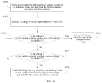
- a braking recovery method for a train proposed in an embodiment of still another aspect of this application includes: braking the train, generating braking electric energy according to a braking force, and feeding back the braking electric energy to a traction network; detecting a voltage of the traction network; controlling a battery according to the voltage of the traction network to absorb the braking electric energy of the train; and controlling an energy storage power station according to the voltage of the traction network to perform charging or discharging.
- the train is braked, the braking electric energy is generated according to the braking force, and the braking electric energy is fed back to the traction network; then the voltage of the traction network is monitored, and the battery is controlled according to the voltage of the traction network to absorb the braking electric energy of the train; the voltage of the traction network continues to be monitored, and whether the voltage of the traction network continues to be increased is judged; and if it is judged that the voltage of the traction network continues to be increased, the energy storage power station is controlled to absorb the braking electric energy.
- the energy storage power station may be further controlled according to the voltage of the traction network to perform discharging, thereby preventing the voltage of the traction network from being excessively low, to maintain normal operating of the traction network.
- the braking electric energy is first fed back to the traction network, and a quantity of trains on the traction network is judged. In this case, if there are a relatively large quantity of trains on the traction network, the fed-back braking electric energy is evened to other trains, and therefore the voltage of the traction network is not increased greatly.
- the in-vehicle battery is preferentially controlled to absorb the braking electric energy, and if the voltage of the traction network continues to be increased after the in-vehicle battery absorbs the braking electric energy, the energy storage power station is controlled to absorb the braking electric energy. Because the in-vehicle battery is mounted onto the train, the battery is preferentially controlled to absorb the braking electric energy, to avoid a problem that the braking electric energy is excessively large and cannot be rapidly absorbed or consumed and consequently an electric appliance of the traction network is burned.
- the battery on the train and the energy storage power station are controlled to absorb the braking electric energy, thereby recovering and reusing the braking electric energy, reducing energy waste, and reducing load on the traction network.
- this embodiment of this application may further effectively monitor the voltage of the traction network, protect system components, and improve system safety.
- the controlling a battery according to the voltage of the traction network to absorb the braking electric energy of the train specifically includes: judging whether the voltage of the traction network is greater than a first preset threshold; and controlling, if the voltage of the traction network is greater than the first preset threshold, the battery to absorb the braking electric energy.
- the braking recovery method for a train further includes: judging whether the voltage of the traction network is less than a second preset threshold; and controlling, if the voltage of the traction network is less than the second preset threshold, the battery to stop absorbing the braking electric energy, where the second preset threshold is less than the first preset threshold.
- the controlling the battery to absorb the braking electric energy further includes the following steps: detecting a power level of the battery, and judging whether the power level of the battery is greater than a first power level threshold; and controlling, if the power level of the battery is greater than the first power level threshold, the battery to stop absorbing the braking electric energy.
- the braking recovery method for a train further includes: judging whether the voltage of the traction network is greater than a third preset threshold; and controlling, when the voltage of the traction network is greater than the third preset threshold, the train to be mechanically braked in cooperation with electric braking to brake the train, where the third preset threshold is greater than the first preset threshold.
- the controlling an energy storage power station according to the voltage of the traction network to perform charging or discharging specifically includes the following steps: judging whether the voltage of the traction network is greater than a fourth preset threshold; and controlling, if the voltage of the traction network is greater than the fourth preset threshold, the energy storage power station to perform charging.
- the braking recovery method for a train further includes: judging whether the voltage of the traction network is less than a fifth preset threshold; and controlling, if the voltage of the traction network is less than the fifth preset threshold, the energy storage power station to perform discharging, where the fifth preset threshold is less than the fourth preset threshold.
- the braking recovery method for a train further includes: judging whether the voltage of the traction network is greater than a sixth preset threshold; and controlling, when the voltage of the traction network is greater than the sixth preset threshold, the energy storage power station to stop discharging, where the sixth preset threshold is greater than the fifth preset threshold.
- the braking recovery method for a train further includes: judging whether the voltage of the traction network is less than a seventh preset threshold; and controlling, if the voltage of the traction network is less than the seventh preset threshold, the energy storage power station to discharge to the traction network, and at the same time, controlling the battery to discharge to the traction network, where the seventh preset threshold is less than the fifth preset threshold.
- the controlling the battery to discharge to the traction network further includes the following steps: detecting a power level of the battery, and judging whether the power level of the battery is less than a second power level threshold; and controlling, if the power level of the battery is less than the second power level threshold, the battery to stop discharging.
- the braking recovery method for a train further includes: detecting whether a contactor of the train is disconnected; and controlling, if it is detected that the contactor is disconnected, the battery to supply power to the train, and controlling the train to run at limited power.
- FIG. 1 is a schematic block diagram of a braking recovery system for a train according to an embodiment of this application.
- the braking recovery system for a train includes: a traction network 1, a plurality of trains 2 connected to the traction network 1, and a plurality of energy storage power stations 3 disposed on the traction network 1.
- the traction network 1 provides a direct current to the plurality of trains 2, and the train 2 is powered from the traction network 1 by using a powering device.
- the train 2 is a straddle-type monorail train.
- braking electric energy generated by the train 2 may be recovered by using a battery of the train 2 and/or the energy storage power station 3.
- the train 2 not only may absorb the braking electric energy generated by the train 2, but also may absorb braking electric energy generated by another train 2. Because a voltage of the traction network 1 is increased when the train 2 feeds back the braking electric energy to the traction network 1, the train 2 and the energy storage power station 3 may monitor the voltage of the traction network 1. When the voltage of the traction network 1 is increased, the braking electric energy may be absorbed by using the battery of the train 2 or the energy storage power station 3, thereby preventing the voltage of the traction network 1 from exceeding a maximum rated voltage to cause a fault.
- a specific absorption process is to be introduced in detail in the following embodiments.
- the braking electric energy absorbed by the battery of the train 2 may be used for power consumption of illumination, air conditioners, and multimedia of the train 2.
- the braking electric energy absorbed by the battery of the train 2 may be further used for emergency driving of the train 2.
- the energy storage power station 3 may be disposed in a station, and absorbed braking electric energy is used to supply power to the station, for example, supply power to air conditioners, multimedia, lighting, and the like of the station.
- the energy storage power stations 3 are spaced apart according to a preset distance.
- two energy storage power stations 3 are disposed within every 3 to 6 kilometers, and power of each energy storage power station 3 is 0.5 to 2 MW.
- a person skilled in the art may select an appropriate quantity of energy storage power stations 3 and appropriate power according to a specific operating environment of the train 2.
- FIG. 2 is a schematic block diagram of a braking recovery system for a train according to an embodiment of this application. For convenience of description, only one energy storage power station is shown in this embodiment.
- the train 2 includes: an electric brake 201, a battery 202, a distributor 203, a bidirectional DC/DC converter 204, and a first controller 205.
- the distributor 203 is connected to a traction network 1 and the electric brake 201, and there is a node between the distributor 203 and the electric brake 201. Specifically, there are a positive node and a negative node between the distributor 203 and the electric brake 201; and a first end of the bidirectional DC/DC converter 204 is connected to the battery 202, a second end of the bidirectional DC/DC converter 204 is connected to the positive node between the distributor 203 and the electric brake 201, and a third end of the bidirectional DC/DC converter 204 is connected to the negative node between the distributor 203 and the electric brake 201.
- the first controller 205 is used to control, when the train is braked, the distributor 203 and the bidirectional DC/DC converter 204 to feed back the braking electric energy to the traction network 1.
- the distributor 203 is enabled, and the bidirectional DC/DC converter 204 is disabled, thereby directly feeding back the braking electric energy to the traction network 1.
- the first controller 205 is connected to the distributor 203 and the bidirectional DC/DC converter 204.
- the first controller 205 is connected to a fourth end of the bidirectional DC/DC converter 204, and the first controller 205 controls, according to the voltage U of the traction network 1, the bidirectional DC/DC converter 204 to be enabled, and controls the bidirectional DC/DC converter 204 to enter a charging mode, to enable the battery 202 to absorb the braking electric energy of the train 2.
- the energy storage power station 3 is connected to the traction network 1, the energy storage power station 3 includes a second controller 301, and the second controller 301 is used to control the energy storage power station 3 according to the voltage U of the traction network 1 to perform charging or discharging.
- the energy storage power station 3 may include at least one energy storage battery and a corresponding bidirectional DC/DC converter.
- the energy storage power station 3 may include a plurality of 160KW-80KWh modules, positive electrodes of the plurality of 160KW-80KWh modules are connected and are connected to a positive electrode of the traction network 1 by using a positive electrode cabinet, and negative electrodes of the plurality of 160KW-80KWh modules are connected and are connected to a negative electrode of the traction network 1 by using a negative electrode cabinet.
- a traction motor is transformed from a motor operating condition to a generator operating condition, and the electric brake 201 generates braking electric energy and feeds back the braking electric energy to the traction network 1.
- the braking electric energy fed back to the traction network 1 exceeds electric energy needed for running the trains on the traction network 1, thereby increasing the voltage U of the traction network 1.
- the first controller 205 monitors the voltage U of the traction network 1 in real time, and when the voltage U of the traction network 1 is increased, the first controller 205 is preferentially used to control the battery 202 of the train 2 to absorb the braking electric energy.
- the second controller 301 of the energy storage power station 3 monitors the voltage U of the traction network 1, and if the voltage U of the traction network 1 continues to be increased after the battery of the train 2 absorbs the braking electric energy, the second controller 301 controls the energy storage power station 3 to absorb electric energy from the traction network 1 to perform charging.
- the second controller 301 of the energy storage power station 3 monitors the voltage U of the traction network 1 in real time, and when the voltage U of the traction network 1 is reduced, the second controller 301 is preferentially used to control the energy storage power station 3 to perform discharging to increase the voltage of the traction network 1. If the voltage U of the traction network 1 continues to be reduced, the first controller 205 may also control the battery 202 to perform discharging to increase the voltage of the traction network 1.
- the battery 202 of the train 2 may supply power to illumination, air conditioners, and multimedia of the train.
- the energy storage power station 3 may be disposed in a station, so as to use recovered braking electric energy to supply power to illumination, air conditioners, multimedia, and the like of the station. In this way, the braking electric energy may be recovered and reused by using the battery 202 and the energy storage power station 3, and load on a substation may be reduced, thereby saving energy.
- the battery 202 is disposed on the train 2, and may rapidly absorb the braking electric energy generated the train, and because a distance between the energy storage power station 3 and the train 2 is relatively large, the energy storage power station 3 is delayed in absorbing the braking electric energy. Therefore, in this embodiment of this application, the battery 202 is preferentially selected to absorb braking electric energy, so as to rapidly absorb the braking electric energy, thereby preventing braking electric energy that is not absorbed or consumed from increasing the voltage U of the traction network 1, protecting system components, preventing an electric appliance on the traction network 1 from being damaged, and improving system safety.
- the braking electric energy is mainly absorbed by the energy storage power station 3.
- the first controller 205 controls the battery 202 to absorb 30% of the braking electric energy
- the second controller 301 controls the energy storage power station 3 to absorb 70% of the braking electric energy, so as to recover the braking electric energy.
- a battery 202 of a non-braked train may be charged by using the non-braked train on the traction network 1.
- braking electric energy not absorbed or consumed on the traction network 1 is Q' and there are N trains on the traction network 1
- an average value of braking electric energy absorbed by batteries 202 of all of the trains on the traction network 1 is Q'/N.
- the braking electric energy generated by braking the train is quite large.
- the battery on the train and the energy storage power station are controlled to absorb the braking electric energy, thereby recovering and reusing the braking electric energy, reducing energy waste, and reducing load on the traction network.
- this embodiment of this application may further effectively monitor the voltage of the traction network, protect system components, and improve system safety.
- a first controller 205 monitors a voltage U of a traction network 1, and when the voltage U of the traction network 1 is greater than a first preset threshold U1 such as 845 V, the first controller 205 controls a bidirectional DC/DC converter 204 to be enabled, and controls the bidirectional DC/DC converter 204 to enter a charging mode, to enable a battery 202 to absorb braking electric energy.
- a first preset threshold U1 such as 845 V
- the first controller 205 controls a bidirectional DC/DC converter 204 to be enabled, and controls the bidirectional DC/DC converter 204 to enter a charging mode, to enable a battery 202 to absorb braking electric energy.
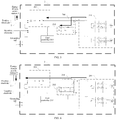
- electric energy in a circuit flows according to a direction indicated by an arrow shown in FIG. 3 , where braking electric energy generated by a train 2 is fed back to the traction network 1, and the battery 202 of the train 2 absorbs the braking electric energy.
- the bidirectional DC/DC converter when the first controller 205 controls the bidirectional DC/DC converter 204 to be enabled, and controls the bidirectional DC/DC converter 204 to enter the charging mode, the bidirectional DC/DC converter converts a direct current on a high-voltage side into a direct current matching a voltage of the battery 202, so as to charge the battery 202, that is, control the battery 202 to absorb the braking electric energy; and when the first controller 205 controls the bidirectional DC/DC converter 204 to be enabled, and controls the bidirectional DC/DC converter 204 to enter a discharging mode, the bidirectional DC/DC converter 204 is used to convert a direct current provided by the battery 202 into a direct current matching the voltage of the traction network 1, so as to control the battery 202 to perform discharging, that is, feed back the braking electric energy stored in the battery 202 to the traction network 1.
- the voltage of the traction network 1 is decreased, and the first controller 205 continues to monitor the voltage U of the traction network 1.
- the first controller 205 controls the bidirectional DC/DC converter 204 to be disabled to enable the battery 202 to stop absorbing the braking electric energy, where the second preset threshold U2 is less than the first preset threshold U1.
- electric energy in a circuit flows according to a direction indicated by an arrow shown in FIG. 4 .
- the braking electric energy generated by the train 2 is fed back to the traction network 1, and neither the battery 202 of the train 2 nor the energy storage power station 3 absorbs the braking electric energy.
- the first controller 205 monitors the voltage U of the traction network 1 in real time. If the voltage U of the traction network 1 is greater than the first preset threshold U1 such as 845 V, indicating that in this case, the braking electric energy fed back to the traction network 1 is surplus, the first controller 205 controls the bidirectional DC/DC converter 204 to operate in the charging mode, so as to charge the battery 202 by using the braking electric energy.
- the first preset threshold U1 such as 845 V
- the braking electric energy generated by the train 2 is fed back to the traction network 1 by using the distributor 203, and the battery 202 is charged by using the bidirectional DC/DC converter 204, that is, a part of the braking electric energy is absorbed by using the battery 202.
- the first controller 205 controls the bidirectional DC/DC converter 204 to be disabled.
- the battery 202 is controlled to stop absorbing the braking electric energy, and the braking electric energy generated by the train 2 is fed back to the traction network 1 by using the distributor 203.
- the battery 202 of the train 2 is preferentially selected to absorb the braking electric energy, so as to rapidly absorb the braking electric energy, thereby preventing the braking electric energy not consumed from increasing the voltage U of the traction network 1, and preventing a device on the traction network 1 from being damaged.
- a second controller 301 monitors a voltage U of a traction network 1, and when the voltage U of the traction network 1 is greater than a fourth preset threshold U4 such as 855 V, the second controller 301 controls an energy storage power station 3 to perform charging.
- a fourth preset threshold U4 such as 855 V
- the second controller 301 controls an energy storage power station 3 to perform charging.
- electric energy in a circuit flows according to a direction indicated by an arrow shown in FIG. 5 .
- the braking electric energy generated by the train 2 is fed back to the traction network 1, and both the battery 202 of the train 2 and the energy storage power station 3 absorb the braking electric energy.
- the voltage of the traction network 1 when the battery of the train 2 begins to absorb the braking electric energy, because a quantity of trains on the traction network 1 is relatively small in this case or a quantity of braked trains 2 is relatively large in this case, the voltage of the traction network 1 further continues to be increased.
- the voltage U of the traction network 1 is greater than the fourth preset threshold U4, the energy storage power station 3 is controlled to absorb electric energy from the traction network 1 to perform charging, thereby preventing the voltage of the traction network 1 from exceeding a maximum rated voltage.
- a second controller 301 monitors a voltage U of a traction network 1, and when the voltage U of the traction network 1 is less than a fifth preset threshold U5 such as 810 V, the second controller 301 controls an energy storage power station 3 to perform discharging, where the fifth preset threshold U5 is less than the fourth preset threshold U4.
- a fifth preset threshold U5 such as 810 V
- the second controller 301 controls an energy storage power station 3 to perform discharging, where the fifth preset threshold U5 is less than the fourth preset threshold U4.
- electric energy in a circuit flows according to a direction indicated by an arrow shown in FIG. 6 . Braking electric energy generated by a train 2 is fed back to the traction network 1, and the energy storage power station 3 discharges to the traction network 1.
- the energy storage power station 3 needs to be controlled to discharge to the traction network 1.
- the second controller 301 monitors the voltage U of the traction network 1. When the voltage U of the traction network 1 is greater than a sixth preset threshold U6, the second controller 301 controls the energy storage power station 3 to stop discharging, where the sixth preset threshold U6 is greater than the fifth preset threshold U5.
- a second controller 301 monitors a voltage U of a traction network 1.
- the second controller 301 controls an energy storage power station 3 to discharge to the traction network 1.
- a first controller 205 controls a bidirectional DC/DC converter 204 to be enabled, and controls the bidirectional DC/DC converter 204 to enter a discharging mode to enable a battery 202 of a train 2 to discharge to the traction network 1, where the seventh preset threshold U7 is less than the fifth preset threshold U5.
- electric energy in a circuit flows according to a direction indicated by an arrow shown in FIG. 7 .
- Braking electric energy generated by a train 2 is fed back to the traction network 1, and both the energy storage power station 3 and the battery 202 discharge to the traction network 1.
- both the energy storage power station 3 and the battery of the train 2 are controlled to perform discharging, thereby rapidly increasing the voltage of the traction network 1.
- the voltage of the traction network 1 continues to be increased after the battery 202 of the train 2 begins to absorb the braking electric energy.
- the second controller 301 controls the energy storage power station 3 to absorb the braking electric energy from the traction network 1 to perform charging, so as to alleviate a pressure of the battery 202 in absorbing the braking electric energy, thereby preventing the voltage U of the traction network 1 from exceeding a maximum rated voltage Un of the traction network 1. As shown in FIG.
- the second controller 301 controls the energy storage power station 3 to discharge to the traction network 1.
- the second controller 301 controls the energy storage power station 3 to stop discharging.
- the voltage U of the traction network 1 continues to be reduced after the energy storage power station 3 is controlled to perform discharging.
- the second controller 301 controls an energy storage power station 3 to discharge to the traction network 1.
- a first controller 205 controls a bidirectional DC/DC converter 204 to be enabled, and controls the bidirectional DC/DC converter 204 to enter a discharging mode to enable a battery 202 of a train 2 to discharge to the traction network 1, thereby rapidly increasing the voltage of the traction network 1.
- Discharging power of the battery 202 is a smaller one of maximum allowable discharging power of the battery 202 and maximum allowable discharging power of the bidirectional DC/DC converter 204.
- the energy storage power station 3 may be disposed in a station, and absorbed braking electric energy is used to supply power to the station, for example, supply power to air conditioners, multimedia, lighting, and the like of the station.
- two energy storage power stations 3 may be disposed within every 3 to 6 kilometers, and power of the energy storage power station 3 may be 0.5 to 2 MW.
- a person skilled in the art may select an appropriate quantity of energy storage power stations 3 and appropriate power according to a specific operating environment of the train 2.
- the train 2 further includes: a power level detector 206, where the power level detector 206 is connected to the first controller 205, and the power level detector 206 is used to detect a power level of the battery 202, where when the battery 202 absorbs the braking electric energy, if the power level Q of the battery 202 is greater than a first power level threshold Q1 such as 80%, the first controller 205 controls the bidirectional DC/DC converter 204 to be disabled to enable the battery 202 to stop absorbing the braking electric energy.
- charging power and discharging power of the battery 202 are limited, the power level of the battery 202 is increased after the battery 202 absorbs the braking electric energy.
- the bidirectional DC/DC converter 204 is controlled to be disabled, so as to control the battery 202 to stop absorbing the braking electric energy.
- the first controller 205 controls the bidirectional DC/DC converter 204 to be disabled to enable the battery 202 to stop discharging.
- the power level of the battery 202 is reduced after the battery 202 discharges, and when the power level Q is less than the second power level threshold Q2, the bidirectional DC/DC converter 204 is controlled to be disabled, so as to control the battery 202 to stop discharging.
- charging power and discharging power of the battery 202 are limited, and when the first controller 205 controls the battery 202 to perform charging/discharging, the power level (state of charge, SOC) of the battery 202 is detected in real time by using the power level detector 206, and whether the battery 202 is allowed to perform charging/discharging is judged according to the power level Q of the battery 202.
- SOC state of charge
- the first controller 205 judges whether the power level Q of the battery 202 is greater than the first power level threshold Q1 such as 80%. If the power level Q of the battery 202 is greater than 80%, maximum allowable charging power of the battery 202 is limited to 0. In this case, the bidirectional DC/DC converter 204 is controlled to be disabled, so as to control the battery 202 to stop absorbing the braking electric energy. If the power level of the battery 202 is less than or equal to 80%, the bidirectional DC/DC converter 204 keeps being enabled, and the bidirectional DC/DC converter 204 is controlled to operate in the charging mode, so as to control the battery 202 to continue to absorb the braking electric energy.
- the first power level threshold Q1 such as 80%. If the power level Q of the battery 202 is greater than 80%, maximum allowable charging power of the battery 202 is limited to 0. In this case, the bidirectional DC/DC converter 204 is controlled to be disabled, so as to control the battery 202 to stop absorbing the braking electric energy. If the power level of the battery
- the first controller 205 judges whether the power level Q of the battery 202 is less than the second power level threshold Q2 such as 50%. If the power level Q of the battery 202 is less than 50%, the maximum allowable discharging power of the battery 202 is limited to 0. In this case, the first controller 205 controls the bidirectional DC/DC converter 204 to be disabled to control the battery 202 to stop discharging.
- the train 2 further includes: a mechanical brake 207, where the mechanical brake 207 is used to mechanically brake the train 2.
- the first controller 205 controls the mechanical brake 207 to be started to brake the train 2 in cooperation with the electric brake 201, where the third preset threshold U3 is greater than the first preset threshold U1.
- the voltage U of the traction network 1 continues to be increased after the battery 202 and the energy storage power station 3 absorb the braking electric energy.
- the mechanical brake 207 is controlled to be started, so as to perform auxiliary braking on the train 2.
- the voltage U of the traction network 1 continues to be increased, and the first controller 205 monitors the voltage U of the traction network 1 in real time. If the voltage U of the traction network 1 is greater than the third preset threshold U3, the first controller 205 controls the mechanical brake 207 to be started. In this way, auxiliary braking is performed on the train 2 through mechanical braking while the train 2 is electrically braked, so as to reduce the braking electric energy generated by the train 2, thereby preventing the voltage U of the traction network 1 from exceeding the maximum rated voltage, and precise and rapid parking may be implemented.
- the mechanical brake 207 may be similarly controlled to be enabled to brake the train 2.
- the train 2 further includes: a contactor detector 208, where the contactor detector 208 is connected to the first controller 205, and the contactor detector 208 is used to detect whether a contactor of the train is disconnected, where after it is detected that the contactor is disconnected, the first controller 205 controls the bidirectional DC/DC converter 204 to be enabled, controls the bidirectional DC/DC converter 204 to enter the discharging mode, to enable the battery 202 to supply power to the train 2, and controls the train 2 to run at limited power.
- a contactor detector 208 is connected to the first controller 205, and the contactor detector 208 is used to detect whether a contactor of the train is disconnected, where after it is detected that the contactor is disconnected, the first controller 205 controls the bidirectional DC/DC converter 204 to be enabled, controls the bidirectional DC/DC converter 204 to enter the discharging mode, to enable the battery 202 to supply power to the train 2, and controls the train 2 to run at limited power.
- the first controller 205 judges that the train 2 enters an emergency driving mode, and sends an emergency traction signal, so as to control the bidirectional DC/DC converter 204 to be enabled, and control the bidirectional DC/DC converter 204 to enter the discharging mode.
- the battery 202 supplies power to the train 2.
- the first controller 205 controls the discharging power of the battery 202 to be less than or equal to a preset power threshold such as 70 KW, to enable the train 2 to run in a limited power state.
- emergency driving of the train is implemented by using the battery 202, to avoid a problem of difficult scheduling caused because the train is broken down midway, and also prevent the faulty train from occupying a running line.
- a voltage level of the traction network 1 is 750 VDC is used, and a policy for recovering and reusing braking electric energy in an embodiment of this application is specifically as follows:
- braking electric energy is allocated comprehensively according to a voltage of the traction network 1, a power level of an in-vehicle battery 202, and a quantity of trains 2 on the traction network 1.
- the first controller 205 preferentially controls the battery 202 to absorb surplus braking electric energy.
- the second controller 301 controls the energy storage power station 3 to absorb the surplus braking electric energy.
- the braking electric energy is fed back to the traction network 1, whether the power level Q of the battery 202 is less than or equal to the first power level threshold Q1 is first judged. If the power level Q is less than or equal to the first power level threshold Q1, the battery 202 may absorb the braking electric energy. In this case, the first controller 205 monitors the voltage U of the traction network 1 in real time. If a quantity of trains on the traction network 1 is relatively small, that is, load on the traction network 1 is relatively small, or a quantity of braked trains on the traction network 1 is relatively large, the voltage of the traction network 1 is increased.
- the battery 202 of the train 2 is controlled to absorb the braking electric energy. If the voltage U of the traction network 1 continues to be increased after the battery of the train 2 absorbs the braking electric energy, when the voltage U of the traction network 1 is greater than the fourth preset threshold U4 such as 855 V, the second controller 301 controls the energy storage power station 3 to absorb the braking electric energy. In this embodiment of this application, after the battery 202 and the energy storage power station 3 are controlled to absorb the braking electric energy, the voltage U of the traction network 1 is reduced. When the voltage U of the traction network 1 is less than or equal to the second preset threshold U2 such as 830 V, the battery 202 and the energy storage power station 3 are controlled to stop absorbing the braking electric energy.
- the second preset threshold U2 such as 830 V
- the energy storage power station 3 is controlled to begin to absorb the braking electric energy; when the voltage U of the traction network 1 is greater than the first preset threshold U1 and less than the fourth preset threshold U4, the battery 202 is controlled to absorb the braking electric energy; and when the voltage U of the traction network 1 is less than the second preset threshold U2, the braking electric energy is fed back to only the traction network 1.
- the voltage U of the traction network 1 is reduced.
- electric energy loss of the traction network 1 may be supplemented by releasing the braking electric energy recovered by the battery 202 and the energy storage power station 3 to the traction network 1.
- whether the power level Q of the battery 202 is greater than or equal to the second power level threshold Q2 is first judged. If the power level Q is greater than or equal to the second power level threshold Q2, the battery 202 may perform discharging. In this case, the second controller 301 monitors the voltage U of the traction network 1 in real time.
- the energy storage power station 3 is controlled to perform discharging. Further, the first controller 205 monitors the voltage U of the traction network 1, and whether the voltage U of the traction network 1 is less than the seventh preset threshold U7 is judged. If the first controller 205 judges that the voltage U of the traction network 1 is less than the seventh preset threshold U7, the second controller 301 controls the energy storage power station 3 to perform discharging. Moreover, the first controller 205 controls the bidirectional DC/DC converter 204 to be enabled, and controls the bidirectional DC/DC converter 204 to enter the discharging mode, to enable the battery 202 of the train 2 to discharge to the traction network 1.
- the fifth preset threshold U5 such as 810 V
- the battery 202 may be controlled to enter the discharging mode, so as to implement emergency driving of the train 2.
- the braking electric energy absorbed by the battery 202 and the energy storage power station 301 may be consumed, to enable the battery 202 and the energy storage power station 301 to continue to recover the braking electric energy, thereby saving the operating costs.
- the first controller controls the distributor and the bidirectional DC/DC converter to feed back the braking electric energy to the traction network, and controls the bidirectional DC/DC converter according to the voltage of the traction network to absorb the braking electric energy of the train by using the battery.
- the energy storage power station is reused to absorb the braking electric energy.
- the energy storage power station may further discharge to the traction network according to the voltage of the traction network, thereby preventing the voltage of the traction network from being excessively low, to maintain normal operating of the traction network.
- the braking electric energy is first fed back to the traction network.
- the fed-back braking electric energy is evened to other trains, and therefore the voltage of the traction network is not increased greatly.
- the voltage of the traction network is increased.
- the in-vehicle battery is preferentially used to absorb the braking electric energy, and if the voltage of the traction network continues to be increased after the in-vehicle battery absorbs the braking electric energy, the energy storage power station is then used to absorb the braking electric energy. Because the in-vehicle battery is mounted onto the train, the battery is preferentially used to absorb the braking electric energy, to avoid a problem that the braking electric energy is excessively large and cannot be rapidly absorbed or consumed and consequently an electric appliance of the traction network is burned.
- the battery on the train and the energy storage power station are used to absorb the braking electric energy, thereby recovering and reusing the braking electric energy, reducing energy waste, and reducing load on the traction network.
- this embodiment of this application may further effectively monitor the voltage of the traction network, protect system components, and improve system safety.
- FIG. 12 is a schematic block diagram of a train according to an embodiment of this application.
- the train 2 includes: an electric brake 201, a battery 202, a distributor 203, a bidirectional DC/DC converter 204, and a first controller 205.
- the distributor 203 is connected to a traction network 1 and the electric brake 201, and there is a node between the distributor 203 and the electric brake 201.
- One end of the bidirectional DC/DC converter 204 is connected to the battery 202, and another end of the bidirectional DC/DC converter 204 is connected to a node between the distributor 203 and the electric brake 201.
- the first controller 205 is connected to the distributor 203 and the bidirectional DC/DC converter 204. The first controller 205 is used to control, when the train 2 is braked, the distributor 203 and the bidirectional DC/DC converter 204 to feed back the braking electric energy to the traction network 1.
- the distributor 203 is enabled, and the bidirectional DC/DC converter 204 is disabled, thereby directly feeding back the braking electric energy to the traction network 1.
- the first controller 205 controls, according to the voltage of the traction network 1, the bidirectional DC/DC converter 204 to be enabled, and controls the bidirectional DC/DC converter 204 to enter a charging mode, to enable the battery 202 to absorb the braking electric energy of the train.
- a traction motor is transformed from a motor operating condition to a generator operating condition, and the electric brake 201 generates braking electric energy and feeds back the braking electric energy to the traction network 1.
- the braking electric energy fed back to the traction network 1 exceeds electric energy needed for running the trains on the traction network 1, thereby increasing the voltage U of the traction network 1.
- the first controller 205 monitors the voltage U of the traction network 1 in real time, and when the voltage U of the traction network 1 is increased, the battery 202 is controlled to absorb the braking electric energy. Similarly, when the quantity of trains on the traction network 1 is relatively large, that is, the load on the traction network 1 is relatively large, the voltage U of the traction network 1 is reduced. The first controller 205 controls the battery 202 to perform discharging to increase the voltage of the traction network 1.
- the battery 202 of the train 2 may supply power to illumination, air conditioners, and multimedia of the train. In this way, the braking electric energy may be recovered and reused by using the battery 202, and load on a substation may be reduced, thereby saving energy.
- the battery 202 is disposed on the train 2, and may rapidly absorb the braking electric energy generated the train. Therefore, in this embodiment of this application, the battery 202 is preferentially selected to absorb braking electric energy, so as to rapidly absorb the braking electric energy, thereby preventing braking electric energy that is not absorbed or consumed from increasing the voltage U of the traction network 1, protecting system components, preventing an electric appliance on the traction network 1 from being damaged, and improving system safety.
- a first controller 205 detects a voltage U of a traction network 1, and when the voltage U of the traction network 1 is greater than a first preset threshold U1 such as 845 V, the first controller 205 controls a bidirectional DC/DC converter 204 to enter a charging mode, to enable a battery 202 to absorb braking electric energy.
- the first controller 205 controls the bidirectional DC/DC converter to enter the charging mode, to convert a direct current on a high-voltage side into a direct current matching a voltage of the battery 202, so as to charge the battery 202, that is, absorb the braking electric energy by using the battery 202.
- the bidirectional DC/DC converter 204 when the first controller 205 controls the bidirectional DC/DC converter to enter the discharging mode, the bidirectional DC/DC converter 204 is used to convert a direct current provided by the battery 202 into a direct current matching the voltage of the traction network 1, so as to control the battery 202 to perform discharging, that is, feed back the braking electric energy stored in the battery 202 to the traction network 1.
- the voltage of the traction network 1 is decreased, and the first controller 205 detects the voltage U of the traction network 1.
- the first controller 205 controls the bidirectional DC/DC converter 204 to be disabled to enable the battery 202 to stop absorbing the braking electric energy, where the second preset threshold U2 is less than the first preset threshold U1.
- the first controller 205 monitors the voltage U of the traction network 1 in real time. If the voltage U of the traction network 1 is greater than the first preset threshold U1 such as 845 V, indicating that in this case, the braking electric energy fed back to the traction network 1 is surplus, the first controller 205 controls the bidirectional DC/DC converter 204 to operate in the charging mode, so as to charge the battery 202 by using the braking electric energy.
- the first preset threshold U1 such as 845 V
- the braking electric energy generated by the train 2 is fed back to the traction network 1 by using the distributor 203, and the battery 202 is charged by using the bidirectional DC/DC converter 204, that is, a part of the braking electric energy is absorbed by using the battery 202.
- the first controller 205 controls the bidirectional DC/DC converter 204 to be disabled.
- the battery 202 is controlled to stop absorbing the braking electric energy, and the braking electric energy generated by the train 2 is fed back to the traction network 1 by using the distributor 203.
- the battery 202 of the train 2 is preferentially selected to absorb the braking electric energy, so as to rapidly absorb the braking electric energy, thereby preventing the braking electric energy not consumed from increasing the voltage U of the traction network 1, and preventing a device on the traction network 1 from being damaged.
- the train 2 further includes: a power level detector 206, where the power level detector 206 is connected to the first controller 205, and the power level detector 206 is used to detect a power level of the battery 202, where when the battery 202 absorbs the braking electric energy, if the power level Q of the battery 202 is greater than the first power level threshold Q1 such as 80%, the first controller 205 controls the bidirectional DC/DC converter 204 to be disabled to enable the battery to stop absorbing the braking electric energy.
- charging power and discharging power of the battery 202 are limited, the power level of the battery 202 is increased after the battery 202 absorbs the braking electric energy.
- the bidirectional DC/DC converter 204 is controlled to be disabled, so as to control the battery 202 to stop absorbing the braking electric energy.
- the first controller 205 controls the bidirectional DC/DC converter 204 to be disabled to enable the battery 202 to stop discharging.
- charging power and discharging power of the battery 202 are limited, and when the first controller 205 controls the battery 202 to perform charging/discharging, the power level (state of charge, SOC) of the battery 202 is detected in real time by using the power level detector 206, and whether the battery 202 is allowed to perform charging/discharging is judged according to the power level Q of the battery 202.
- SOC state of charge
- the first controller 205 judges whether the power level Q of the battery 202 is greater than the first power level threshold Q1 such as 80%. If the power level Q of the battery 202 is greater than 80%, charging power of the battery 202 is limited to 0. In this case, the first controller 205 controls the bidirectional DC/DC converter 204 to be disabled, so as to control the battery 202 to stop absorbing the braking electric energy. If the power level of the battery 202 is less than or equal to 80%, the bidirectional DC/DC converter 204 keeps being enabled, and the bidirectional DC/DC converter 204 is controlled to operate in the charging mode, so as to control the battery 202 to continue to absorb the braking electric energy.
- the first power level threshold Q1 such as 80%. If the power level Q of the battery 202 is greater than 80%, charging power of the battery 202 is limited to 0. In this case, the first controller 205 controls the bidirectional DC/DC converter 204 to be disabled, so as to control the battery 202 to stop absorbing the braking electric energy. If the power level of
- the first controller 205 judges whether the power level Q of the battery 202 is less than the second power level threshold Q2 such as 50%. If the power level Q of the battery 202 is less than 50%, the discharging power of the battery 202 is limited to 0. In this case, the first controller 205 controls the bidirectional DC/DC converter 204 to be disabled to control the battery 202 to stop discharging.
- the train 2 further includes: a mechanical brake 207, where the mechanical brake 207 is used to mechanically brake the train 2.
- the first controller 205 controls the mechanical brake 207 to be started to brake the train 2 in cooperation with the electric brake 201, where the third preset threshold U3 is greater than the first preset threshold U1.
- the voltage U of the traction network 1 continues to be increased after the battery 202 absorbs the braking electric energy.
- the mechanical brake 207 is controlled to be started, so as to perform auxiliary braking on the train 2.
- the first controller 205 monitors the voltage U of the traction network 1 in real time. If the voltage U of the traction network 1 is greater than the third preset threshold U3, the first controller 205 controls the mechanical brake 207 to be started. In this way, auxiliary braking is performed on the train 2 through mechanical braking while the train 2 is electrically braked, so as to reduce the braking electric energy generated by the train 2, thereby preventing the voltage U of the traction network 1 from exceeding the maximum rated voltage, and precise and rapid parking may be implemented.
- the mechanical brake 207 may be similarly controlled to be enabled to brake the train 2.
- the train 2 further includes: a contactor detector 208, where the contactor detector 208 is connected to the first controller 205, and the contactor detector 208 is used to detect whether a contactor of the train 2 is disconnected, where after it is detected that the contactor is disconnected, the first controller 205 controls the bidirectional DC/DC converter 204 to enter the discharging mode, to enable the battery 202 to supply power to the train 2, and controls the train 2 to run at limited power.
- the first controller 205 judges that the train 2 enters an emergency driving mode, and sends an emergency traction signal, so as to control the bidirectional DC/DC converter 204 to be enabled, and control the bidirectional DC/DC converter 204 to enter the discharging mode.
- the battery 202 supplies power to the train 2.
- the first controller 205 controls the discharging power of the battery 202 to be less than or equal to a preset power threshold such as 70 KW, to enable the train 2 to run in a limited power state.
- emergency driving of the train is implemented by using the battery 202, to avoid a problem of difficult scheduling caused because the train is broken down midway, and also prevent the faulty train from occupying a running line.
- the train 2 may be a straddle-type monorail train.
- the train 2 further includes: a bogie 20 and a vehicle body 30, where the bogie 20 is suitable for straddling a rail beam; and the vehicle body 30 is connected to the bogie 20 and pulled by the bogie 20 to travel along the rail beam.
- the bogie 20 includes: a bogie frame 21, a running wheel 22, a power device 23, and a horizontal wheel 24, where the bogie frame 21 is suitable for straddling the rail beam and connected to the vehicle body 30; the running wheel 22 is pivotably mounted onto the bogie frame 21 and fits in on an upper surface of the rail beam; the power device 23 is mounted onto the bogie frame 21 and is in transmission connection to the running wheel 22; and the horizontal wheel 24 is pivotably mounted onto the bogie frame 21 and fits in on a side surface of the rail beam.
- the bogie 20 further includes: a traction device 25 and a support suspension device 26, where the traction device 25 is mounted onto the bogie frame 21 and connected to the vehicle body 30; and the support suspension device 26 is mounted onto the bogie frame 21 and connected to the vehicle body 30.
- the first controller is used to control the distributor and the bidirectional DC/DC converter to feed back the braking electric energy to the traction network, and control the bidirectional DC/DC converter according to the voltage of the traction network to absorb the braking electric energy of the train by using the battery.
- the battery may further discharge to the traction network according to the voltage of the traction network, thereby preventing the voltage of the traction network from being excessively low, to maintain normal operating of the traction network.
- the braking electric energy is first fed back to the traction network.
- the in-vehicle battery is preferentially used to absorb the braking electric energy, to avoid a problem that the braking electric energy is excessively large and cannot be rapidly absorbed or consumed and consequently an electric appliance of the traction network is burned.
- the battery on the train is used to absorb the braking electric energy, thereby recovering and reusing the braking electric energy, reducing energy waste, and reducing load on the traction network.
- this embodiment of this application may further effectively monitor the voltage of the traction network, protect system components, and improve system safety.
- FIG. 17 is a flowchart of a braking recovery method for a train according to an embodiment of this application. As shown in FIG. 17 , the braking recovery method includes:
- the train is braked, the braking electric energy is generated according to the braking force, and the braking electric energy is fed back to the traction network.
- the braking electric energy fed back to the traction network exceeds electric energy needed for running the trains on the traction network, thereby increasing the voltage U of the traction network.
- the voltage U of the traction network is monitored in real time. When the voltage U of the traction network is increased, the battery is first controlled to absorb the braking electric energy. Moreover, the voltage of the traction network continues to be monitored.
- the energy storage power station is controlled to absorb the braking electric energy to perform charging.
- the voltage U of the traction network is reduced.
- the voltage U of the traction network is monitored in real time.
- the energy storage power station is first controlled to perform discharging to increase the voltage of the traction network. If the voltage U of the traction network continues to be reduced, the battery is controlled to perform discharging to increase the voltage of the traction network.
- the battery is disposed on the train, and may rapidly absorb the braking electric energy, and because a distance between the energy storage power station and the train is relatively large, the energy storage power station is delayed in absorbing the braking electric energy. Therefore, in this embodiment of this application, the battery is preferentially selected to absorb braking electric energy, so as to rapidly absorb the braking electric energy, thereby preventing braking electric energy that is not absorbed or consumed from increasing the voltage U of the traction network, protecting system components, preventing an electric appliance on the traction network from being damaged, and improving system safety.
- the braking electric energy is mainly absorbed by the energy storage power station.
- the battery is controlled to absorb 30% of the braking electric energy, and then the energy storage power station is controlled to absorb 70% of the braking electric energy, so as to recover the braking electric energy.
- a battery of a non-braked train may be charged by using the non-braked train on the traction network.
- braking electric energy not absorbed or consumed on the traction network is Q' and there are N trains on the traction network
- an average value of braking electric energy absorbed by batteries of all of the trains on the traction network is Q'/N.
- the battery on the train is controlled to absorb the braking electric energy, thereby recovering and reusing the braking electric energy, reducing energy waste, and reducing load on the traction network.
- this embodiment of this application may further effectively monitor the voltage of the traction network, protect system components, and improve system safety.
- the controlling a battery according to the voltage of the traction network to absorb the braking electric energy of the train specifically includes: judging whether the voltage of the traction network is greater than a first preset threshold such as 845 V; and controlling, if the voltage of the traction network is greater than the first preset threshold, a bidirectional DC/DC converter of the train to be enabled, and controlling the bidirectional DC/DC converter to enter a charging mode, so as to control the battery to absorb the braking electric energy.
- the bidirectional DC/DC converter is controlled to convert a direct current on a high-voltage side into a direct current matching a voltage of the battery, so as to charge the battery, that is, control the battery to absorb the braking electric energy.
- a direct current provided by the battery is converted into a direct current matching the voltage of the traction network, so as to control the battery to perform discharging, that is, feed back the braking electric energy stored in the battery to the traction network.
- the controlling a battery according to the voltage of the traction network to absorb the braking electric energy of the train further includes: judging whether the voltage of the traction network is less than a second preset threshold such as 830 V; and controlling, if the voltage of the traction network is less than the second preset threshold, the battery to stop absorbing the braking electric energy, where the second preset threshold is less than the first preset threshold.
- the controlling a battery to absorb the braking electric energy of the train specifically includes:
- S104 is performed; or if not, indicating that the braking electric energy fed back to the traction network in this case and a load requirement on the traction network are basically balanced, S105 is performed.
- S104 Control a battery to absorb a part of the braking electric energy.
- S105 Judge whether the voltage U of the traction network is less than a second preset threshold U2 such as 830 V.
- S106 Control the battery to stop absorbing the braking electric energy, and feed back the braking electric energy generated by the train to the traction network.
- the battery of the train is preferentially selected to absorb the braking electric energy, so as to rapidly absorb the braking electric energy, thereby preventing the braking electric energy not consumed from increasing the voltage U of the traction network, and preventing a device on the traction network from being damaged.
- the controlling an energy storage power station according to the voltage of the traction network to perform charging or discharging specifically includes: judging whether the voltage of the traction network is greater than a fourth preset threshold such as 855 V; and controlling, if the voltage of the traction network is greater than the fourth preset threshold, the energy storage power station to perform charging.
- a fourth preset threshold such as 855 V
- the voltage of the traction network further continues to be increased.
- the energy storage power station is controlled to absorb electric energy from the traction network to perform charging, thereby preventing the voltage of the traction network from exceeding a maximum rated voltage.
- the controlling an energy storage power station according to the voltage of the traction network to perform charging or discharging further includes: judging whether the voltage of the traction network is less than a fifth preset threshold such as 810 V; and controlling, if the voltage of the traction network is less than the fifth preset threshold, the energy storage power station to perform discharging, where the fifth preset threshold is less than the fourth preset threshold.
- a fifth preset threshold such as 810 V
- the controlling an energy storage power station according to the voltage of the traction network to perform charging or discharging further includes: judging whether the voltage of the traction network is less than a fifth preset threshold such as 810 V; and controlling, if the voltage of the traction network is less than the fifth preset threshold, the energy storage power station to perform discharging, where the fifth preset threshold is less than the fourth preset threshold.
- an energy storage power station whose power level is high is preferentially selected to discharge to the traction network.
- discharging power of the energy storage power station whose power level is high is large, and discharging power of an energy storage power station whose power level is low is slightly small, thereby achieving a power level balance between the energy storage power stations.
- the braking recovery method for a train further includes: judging whether the voltage of the traction network is greater than a sixth preset threshold; and controlling, when the voltage of the traction network is greater than the sixth preset threshold, the energy storage power station to stop discharging, where the sixth preset threshold is greater than the fifth preset threshold.
- the braking recovery method for a train further includes: judging whether the voltage of the traction network is less than a seventh preset threshold; and controlling, if the voltage of the traction network is less than the seventh preset threshold, the energy storage power station to discharge to the traction network, and at the same time, controlling the battery to discharge to the traction network, where the seventh preset threshold is less than the fifth preset threshold.
- the voltage U of the traction network is excessively small, both the energy storage power station and the battery of the train are controlled to perform discharging, thereby rapidly increasing the voltage of the traction network.
- the controlling an energy storage power station to absorb the braking electric energy of the train specifically includes:
- S203 Control an energy storage power station to perform charging.
- absorption of the braking electric energy by using the energy storage power station may alleviate a pressure of the battery in absorbing the braking electric energy, thereby preventing the voltage U of the traction network from exceeding a maximum rated voltage Un of the traction network.
- S204 Judge whether the voltage U of the traction network is less than a fifth preset threshold U5 such as 810 V.
- S205 Control the energy storage power station to perform discharging.
- S208 Judge whether the voltage U of the traction network is greater than a sixth preset threshold U6 such as 830 V.
- S210 Judge whether the voltage U of the traction network is less than a seventh preset threshold U7.
- the braking recovery method for a train further includes: judging whether the voltage of the traction network is greater than a third preset threshold; and controlling, when the voltage of the traction network is greater than the third preset threshold, the train to be mechanically braked in cooperation with electric braking to brake the train, where the third preset threshold is greater than the first preset threshold.
- the voltage U of the traction network continues to be increased after the battery and the energy storage power station absorb the braking electric energy.
- the train is controlled to be mechanically braked, so as to perform auxiliary braking on the train.
- the voltage U of the traction network continues to be increased.
- the voltage U of the traction network is monitored in real time. If the voltage U of the traction network is greater than the third preset threshold U3, the train is controlled to be mechanically braked. In this way, auxiliary braking is performed on the train through mechanical braking while the train is electrically braked, so as to reduce the braking electric energy generated by the train, thereby preventing the voltage U of the traction network from exceeding the maximum rated voltage, and precise and rapid parking may be implemented.
- the braking recovery method for a train further includes: detecting whether a contactor of the train is disconnected; and controlling, if it is detected that the contactor is disconnected, the battery to supply power to the train, and controlling the train to run at limited power.
- the battery supplies power to the train.
- the discharging power of the battery is controlled to be less than or equal to a preset power threshold such as 70 KW, to enable the train to run in a limited power state.
- emergency driving of the train is implemented by using the battery, to avoid a problem of difficult scheduling caused because the train is broken down midway, and also prevent the faulty train from occupying a running line.
- the braking recovery method for a train further includes: detecting a power level of the battery, and judging whether the power level of the battery is greater than a first power level threshold such as 80%; and controlling, if the power level of the battery is greater than the first power level threshold, the battery to stop absorbing the braking electric energy.
- a first power level threshold such as 80%
- the battery to stop absorbing the braking electric energy.
- the braking recovery method for a train further includes: detecting a power level of the battery, and judging whether the power level of the battery is less than a second power level threshold such as 50%; and controlling, if the power level of the battery is less than the second power level threshold, the battery to stop discharging.
- the power level of the battery is reduced after the battery discharges, and when the power level Q is less than the second power level threshold Q2, the battery is controlled to stop discharging.
- charging power and discharging power of a battery are limited by using a method shown in FIG. 20 .
- S301 Judge whether a train is in an emergency driving mode.
- S302 Detect a power level Q of a battery in real time.
- S303 Judge whether the power level Q of the battery is greater than a first power level threshold Q1 such as 80%.
- S304 Control the battery to stop absorbing braking electric energy. In this case, maximum allowable charging power of the battery is limited to 0.
- S305 Judge whether the power level Q of the battery is less than a second power level threshold Q2 such as 50%.
- S306 Control the battery to stop discharging. In this case, maximum allowable discharging power of the battery is limited to 0.
- S303 and S304 are performed in a charging process of the battery, and S305 and S306 are performed in a discharging process of the battery.
- recovery and reuse of braking electric energy in an embodiment of this application is specifically as follows:
- S401 Brake a train, generate braking electric energy according to a braking force, and feed back the braking electric energy to a traction network.
- S402 Judge whether a power level Q of a battery is less than or equal to a first power level threshold Q1.
- S403 Monitor a voltage U of the traction network in real time.
- S404 Judge whether the voltage U of the traction network is greater than a first preset threshold U1 such as 845 V.
- S405 Control the battery to absorb the braking electric energy.
- S407 Judge whether the voltage U of the traction network is greater than a fourth preset threshold U4 such as 855 V.
- S408 Control an energy storage power station to absorb the braking electric energy, and return to S407.
- S501 Judge whether a power level Q of a battery is greater than or equal to a second power level threshold Q2.
- S502 Monitor a voltage U of a traction network.
- S503 Judge whether the voltage U of the traction network is less than a fifth preset threshold U5 such as 810 V.
- S504 Control an energy storage power station to perform discharging.
- S505 Control the energy storage power station not to perform discharging.
- S506 Judge whether the voltage U of the traction network is less than a seventh preset threshold U7.
- S507 Control the energy storage power station to discharge to the traction network, and at the same time, control the battery to discharge to the traction network; and return to S506.
- the battery may be controlled to enter the discharging mode, so as to implement emergency driving of the train.
- the braking electric energy absorbed by the battery and the energy storage power station may be consumed, to enable the battery and the energy storage power station to continue to recover the braking electric energy, thereby saving the operating costs.
- the train is braked, the braking electric energy is generated according to the braking force, and the braking electric energy is fed back to the traction network; then the voltage of the traction network is monitored, and the battery is controlled according to the voltage of the traction network to absorb the braking electric energy of the train; the voltage of the traction network continues to be monitored, and whether the voltage of the traction network continues to be increased is judged; and if it is judged that the voltage of the traction network continues to be increased, the energy storage power station is controlled to absorb the braking electric energy.
- the energy storage power station may be further controlled according to the voltage of the traction network to perform discharging, thereby preventing the voltage of the traction network from being excessively low, to maintain normal operating of the traction network.
- the braking electric energy is first fed back to the traction network, and a quantity of trains on the traction network is judged. In this case, if there are a relatively large quantity of trains on the traction network, the fed-back braking electric energy is evened to other trains, and therefore the voltage of the traction network is not increased greatly.
- the in-vehicle battery is preferentially controlled to absorb the braking electric energy, and if the voltage of the traction network continues to be increased after the in-vehicle battery absorbs the braking electric energy, the energy storage power station is controlled to absorb the braking electric energy. Because the in-vehicle battery is mounted onto the train, the battery is preferentially controlled to absorb the braking electric energy, to avoid a problem that the braking electric energy is excessively large and cannot be rapidly absorbed or consumed and consequently an electric appliance of the traction network is burned.
- the battery on the train and the energy storage power station are controlled to absorb the braking electric energy, thereby recovering and reusing the braking electric energy, reducing energy waste, and reducing load on the traction network.
- this embodiment of this application may further effectively monitor the voltage of the traction network, protect system components, and improve system safety.
- orientations or position relationships indicated by terms such as “center”, “longitudinal”, “transverse”, “length”, “width”, “thickness”, “up”, “down”, “front”, “back”, “left”, “right”, “vertical”, “horizontal”, “top”, “bottom”, “inner”, “outer”, “clockwise”, “counterclockwise”, “axial”, “radial”, and “circumferential” are orientations or position relationship shown based on the accompanying drawings, and are merely used for describing this application and simplifying the description, rather than indicating or implying that the apparatus or element should have a particular orientation or be constructed and operated in a particular orientation, and therefore, should not be construed as a limitation on this application.
- first and second are used only for description objectives, and shall not be construed as indicating or implying relative importance or implying a quantity of indicated technical features. Therefore, a feature restricted by “first” or “second” may explicitly indicate or implicitly include at least one such feature. In the description of this application, unless otherwise specifically limited, “multiple” means at least two, for example, two or three.
- the terms “mounted”, “connected”, “connection”, and “fixed” should be understood broadly, for example, which may be fixed connections, detachable connections or integral connections; may be mechanical connections or electrical connections; may be direct connections, indirectly connected with each other through an intermediate medium, or communications inside two elements or an interaction relationship of two elements, unless otherwise specifically limited. Those of ordinary skill in the art can understand specific meanings of the terms in this application according to specific situations.
- a first characteristic "on” or “under” a second characteristic may be the first characteristic in direct contact with the second characteristic, or the first characteristic in indirect contact with the second characteristic by using an intermediate medium.
- the first characteristic "on”, “above “ and “over” the second characteristic may be the first characteristic right above or obliquely above the second characteristic, or only indicates that a horizontal height of the first characteristic is greater than that of the second characteristic.
- the first characteristic "under”, “below “ and “beneath” the second characteristic may be the first characteristic right below or obliquely below the second characteristic, or only indicates that a horizontal height of the first characteristic is less than that of the second characteristic.
- references such as reference terms “an embodiment”, “some embodiments”, “example”, “specific example”, or “some examples” intend to indicate that specific features, structures, materials, or characteristics described with reference to embodiments or examples are included in at least one embodiment or example of this application.
- exemplary descriptions of the foregoing terms do not necessarily refer to a same embodiment or example.
- the described specific feature, structure, material, or characteristic may be combined in a proper manner in any one or more embodiments or examples.
- a person skilled in the art can integrate and combine different embodiments or examples and features of the different embodiments and examples described in this specification.
Landscapes
- Engineering & Computer Science (AREA)
- Mechanical Engineering (AREA)
- Transportation (AREA)
- Power Engineering (AREA)
- Automation & Control Theory (AREA)
- Life Sciences & Earth Sciences (AREA)
- Sustainable Development (AREA)
- Sustainable Energy (AREA)
- Electric Propulsion And Braking For Vehicles (AREA)
Abstract
Description
- This application is proposed based on Chinese Patent Application No.
201610839860.3, filed on September 21, 2016 - This application relates to the field of rail transport technologies, and in particular, to a braking recovery system for a train, a train having the system, and a braking recovery method for a train.
- With continuous expansion of city scales and increasing jam of transport, a rail train such as a light rail or a subway has become a main transport manner in many cities currently. When a train is being braked, a large quantity of braking electric energy is generated. With continuous deepening of a green environmental protection idea, an issue of recovering and reusing the braking electric energy of the train has been quite urgent. Currently, the related art has disclosed that, a battery is disposed in a train to recover braking electric energy and supply power to the train. However, braking electric energy generated when the train is braked is quite large, and if the braking electric energy is to be absorbed by using an in-vehicle battery, a large quantity of batteries need to be mounted onto the train, which severely increases the weight of the train, affects energy consumption of the train during running, and further increases unnecessary costs.
- An objective of this application is to at least resolve one of the technical problems in the related art to some extent. To this end, an objective of this application is to propose a braking recovery system for a train, and the system can recover and reuse braking electric energy.
- Another objective of this application is to propose a train. Still another objective of this application is to propose a braking recovery method for a train.
- To achieve the foregoing objectives, a braking recovery system for a train proposed in an embodiment of an aspect of this application includes: a traction network, a train, and an energy storage power station. The train includes: an electric brake; a battery; a distributor, where the distributor is connected to the electric brake, and there is a node between the distributor and the electric brake; a bidirectional DC/DC converter, where one end of the bidirectional DC/DC converter is connected to the battery, and another end of the bidirectional DC/DC converter is connected to the node; and a first controller, where the first controller is connected to the distributor and the bidirectional DC/DC converter, and the first controller is used to control, when the train is braked, the distributor and the bidirectional DC/DC converter to feed back braking electric energy of the train to the traction network, and control the bidirectional DC/DC converter according to a voltage of the traction network to absorb the braking electric energy of the train by using the battery. The energy storage power station is connected to the traction network, the energy storage power station includes a second controller, and the second controller is used to control the energy storage power station according to the voltage of the traction network to perform charging or discharging.
- According to the braking recovery system for a train proposed in this embodiment of this application, when the train is braked, the first controller controls the distributor and the bidirectional DC/DC converter to feed back the braking electric energy to the traction network, and controls the bidirectional DC/DC converter according to the voltage of the traction network to absorb the braking electric energy of the train by using the battery. When the voltage of the traction network continues to be increased, the energy storage power station is reused to absorb the braking electric energy. Moreover, the energy storage power station may further discharge to the traction network according to the voltage of the traction network, thereby preventing the voltage of the traction network from being excessively low, to maintain normal operating of the traction network. In this embodiment of this application, when the train is braked, the braking electric energy is first fed back to the traction network. In this case, if there are a relatively large quantity of trains on the traction network, the fed-back braking electric energy is evened to other trains, and therefore the voltage of the traction network is not increased greatly. On the contrary, if there are a relatively small quantity of trains on the traction network in this case, or a relatively large quantity of trains are braked in this case, the voltage of the traction network is increased. In this embodiment of this application, the in-vehicle battery is preferentially used to absorb the braking electric energy, and if the voltage of the traction network continues to be increased after the in-vehicle battery absorbs the braking electric energy, the energy storage power station is then used to absorb the braking electric energy. Because the in-vehicle battery is mounted onto the train, the battery is preferentially used to absorb the braking electric energy, to avoid a problem that the braking electric energy is excessively large and cannot be rapidly absorbed or consumed and consequently an electric appliance of the traction network is burned. In this embodiment of this application, the battery on the train and the energy storage power station are used to absorb the braking electric energy, thereby recovering and reusing the braking electric energy, reducing energy waste, and reducing load on the traction network. Moreover, this embodiment of this application may further effectively monitor the voltage of the traction network, protect system components, and improve system safety.
- According to an embodiment of this application, the first controller is used to control, when the voltage of the traction network is greater than a first preset threshold, the bidirectional DC/DC converter to enter a charging mode to enable the battery to absorb the braking electric energy.
- According to an embodiment of this application, the first controller is used to control, when the voltage of the traction network is less than a second preset threshold, the bidirectional DC/DC converter to be disabled to enable the battery to stop absorbing the braking electric energy, where the second preset threshold is less than the first preset threshold.
- According to an embodiment of this application, the train further includes: a power level detector, where the power level detector is connected to the first controller, and the power level detector is used to detect a power level of the battery, where when the battery absorbs the braking electric energy, the first controller is further used to control, when the power level of the battery is greater than a first power level threshold, the bidirectional DC/DC converter to be disabled to enable the battery to stop absorbing the braking electric energy.
- According to an embodiment of this application, the train further includes: a mechanical brake, used to mechanically brake the train.
- According to an embodiment of this application, after the battery absorbs the braking electric energy, the first controller is further used to control, when the voltage of the traction network is greater than a third preset threshold, the mechanical brake to be started to brake the train in cooperation with the electric brake, where the third preset threshold is greater than the first preset threshold.
- According to an embodiment of this application, the second controller is used to control, when the voltage of the traction network is greater than a fourth preset threshold, the energy storage power station to perform charging.
- According to an embodiment of this application, the second controller is further used to control, when the voltage of the traction network is less than a fifth preset threshold, the energy storage power station to perform discharging, where the fifth preset threshold is less than the fourth preset threshold.
- According to an embodiment of this application, after the energy storage power station discharges to the traction network, the second controller is further used to control, when the voltage of the traction network is greater than a sixth preset threshold, the energy storage power station to stop discharging, where the sixth preset threshold is greater than the fifth preset threshold.
- According to an embodiment of this application, when the voltage of the traction network is less than a seventh preset threshold, the second controller controls the energy storage power station to discharge to the traction network, and at the same time, the first controller controls the bidirectional DC/DC converter to enter a discharging mode to enable the battery of the train to discharge to the traction network, where the seventh preset threshold is less than the fifth preset threshold.
- According to an embodiment of this application, when the battery discharges to the traction network, the first controller is further used to control, when the power level of the battery is less than a second power level threshold, the bidirectional DC/DC converter to be disabled to enable the battery to stop discharging.
- According to an embodiment of this application, the train further includes: a contactor detector, where the contactor detector is connected to the first controller, and the contactor detector is used to detect whether a contactor of the train is disconnected, where the first controller is further used to: after the contactor is disconnected, control the distributor to be disabled, control the bidirectional DC/DC converter to enter the discharging mode to enable the battery to supply power to the train, and control the train to run at limited power.
- According to an embodiment of this application, there may be a plurality of energy storage power stations, and the plurality of energy storage power stations is spaced apart according to a preset distance.
- According to an embodiment of this application, two energy storage power stations are disposed within every 3 to 6 kilometers, and power of the energy storage power station may be 0.5 to 2 MW.
- To achieve the foregoing objectives, a train proposed in an embodiment of another aspect of this application includes: an electric brake; a battery; a distributor, where the distributor is connected to the electric brake, and there is a node between the distributor and the electric brake; a bidirectional DC/DC converter, where one end of the bidirectional DC/DC converter is connected to the battery, and another end of the bidirectional DC/DC converter is connected to the node; and a first controller, where the first controller is connected to the distributor and the bidirectional DC/DC converter, and the first controller is used to control, when the train is braked, the distributor and the bidirectional DC/DC converter to feed back braking electric energy of the train to the traction network, and control the bidirectional DC/DC converter according to a voltage of the traction network to absorb the braking electric energy of the train by using the battery.
- When the train proposed according to this embodiment of this application is braked, the first controller is used to control the bidirectional DC/DC converter to feed back the braking electric energy to the traction network, and control the bidirectional DC/DC converter according to the voltage of the traction network to absorb the braking electric energy of the train by using the battery. In this embodiment of this application, when the train is braked, the braking electric energy is first fed back to the traction network. In this case, if there are a relatively large quantity of trains on the traction network, the fed-back braking electric energy is evened to other trains, and therefore the voltage of the traction network is not increased greatly. On the contrary, if there are a relatively small quantity of trains on the traction network in this case, or a relatively large quantity of trains are braked in this case, the voltage of the traction network is increased. In this embodiment of this application, the in-vehicle battery is preferentially used to absorb the braking electric energy, to avoid a problem that the braking electric energy is excessively large and cannot be rapidly absorbed or consumed and consequently an electric appliance of the traction network is burned. In this embodiment of this application, the battery on the train is used to absorb the braking electric energy, thereby recovering and reusing the braking electric energy, reducing energy waste, and reducing load on the traction network. Moreover, this embodiment of this application may further effectively monitor the voltage of the traction network, protect system components, and improve system safety.
- According to an embodiment of this application, the first controller is used to control, when the voltage of the traction network is greater than a first preset threshold, the bidirectional DC/DC converter to enter a charging mode to enable the battery to absorb the braking electric energy.
- According to an embodiment of this application, the first controller is used to control, when the voltage of the traction network is less than a second preset threshold, the bidirectional DC/DC converter to be disabled to enable the battery to stop absorbing the braking electric energy, where the second preset threshold is less than the first preset threshold.
- According to an embodiment of this application, the train further includes: a power level detector, where the power level detector is connected to the first controller, and the power level detector is used to detect a power level of the battery, where when the battery absorbs the braking electric energy, the first controller is further used to control, when the power level of the battery is greater than a first power level threshold, the bidirectional DC/DC converter to be disabled to enable the battery to stop absorbing the braking electric energy.
- According to an embodiment of this application, the train further includes: a mechanical brake, used to mechanically brake the train.
- According to an embodiment of this application, after the battery absorbs the braking electric energy, the first controller is further used to control, when the voltage of the traction network is greater than a third preset threshold, the mechanical brake to be started to brake the train in cooperation with the electric brake, where the third preset threshold is greater than the first preset threshold.
- According to an embodiment of this application, when the battery discharges to the traction network, the first controller is further used to control, when the power level of the battery is less than a second power level threshold, the bidirectional DC/DC converter to be disabled to enable the battery to stop discharging.
- According to an embodiment of this application, the train further includes: a contactor detector, where the contactor detector is connected to the first controller, and the contactor detector is used to detect whether a contactor of the train is disconnected, where the first controller is further used to: after the contactor is disconnected, control the bidirectional DC/DC converter to enter the discharging mode to enable the battery to supply power to the train, and control the train to run at limited power.
- According to an embodiment of this application, the train may be a straddle-type monorail train.
- According to an embodiment of this application, the train further includes: a bogie, where the bogie is suitable for straddling a rail beam; and a vehicle body, where the vehicle body is connected to the bogie and pulled by the bogie to travel along the rail beam.
- According to an embodiment of this application, the bogie includes: a bogie frame, where the bogie frame is suitable for straddling the rail beam and connected to the vehicle body; a running wheel, where the running wheel is pivotably mounted onto the bogie frame and fits in on an upper surface of the rail beam; a power device, where the power device is mounted onto the bogie frame and is in transmission connection to the running wheel; and a horizontal wheel, where the horizontal wheel is pivotably mounted onto the bogie frame and fits in on a side surface of the rail beam.
- According to an embodiment of this application, the bogie further includes: a traction device, where the traction device is mounted onto the bogie frame and connected to the vehicle body; and a support suspension device, where the support suspension device is mounted onto the bogie frame and connected to the vehicle body.
- To achieve the foregoing objectives, a braking recovery method for a train proposed in an embodiment of still another aspect of this application includes: braking the train, generating braking electric energy according to a braking force, and feeding back the braking electric energy to a traction network; detecting a voltage of the traction network; controlling a battery according to the voltage of the traction network to absorb the braking electric energy of the train; and controlling an energy storage power station according to the voltage of the traction network to perform charging or discharging.
- According to the braking recovery method for a train proposed in this embodiment of this application, at first, the train is braked, the braking electric energy is generated according to the braking force, and the braking electric energy is fed back to the traction network; then the voltage of the traction network is monitored, and the battery is controlled according to the voltage of the traction network to absorb the braking electric energy of the train; the voltage of the traction network continues to be monitored, and whether the voltage of the traction network continues to be increased is judged; and if it is judged that the voltage of the traction network continues to be increased, the energy storage power station is controlled to absorb the braking electric energy. Moreover, the energy storage power station may be further controlled according to the voltage of the traction network to perform discharging, thereby preventing the voltage of the traction network from being excessively low, to maintain normal operating of the traction network. In this embodiment of this application, after the train is braked, the braking electric energy is first fed back to the traction network, and a quantity of trains on the traction network is judged. In this case, if there are a relatively large quantity of trains on the traction network, the fed-back braking electric energy is evened to other trains, and therefore the voltage of the traction network is not increased greatly. On the contrary, if there are a relatively small quantity of trains on the traction network or a relatively large quantity of trains are braked in this case, the voltage of the traction network is rapidly increased. In this embodiment of this application, the in-vehicle battery is preferentially controlled to absorb the braking electric energy, and if the voltage of the traction network continues to be increased after the in-vehicle battery absorbs the braking electric energy, the energy storage power station is controlled to absorb the braking electric energy. Because the in-vehicle battery is mounted onto the train, the battery is preferentially controlled to absorb the braking electric energy, to avoid a problem that the braking electric energy is excessively large and cannot be rapidly absorbed or consumed and consequently an electric appliance of the traction network is burned. In this embodiment of this application, the battery on the train and the energy storage power station are controlled to absorb the braking electric energy, thereby recovering and reusing the braking electric energy, reducing energy waste, and reducing load on the traction network. Moreover, this embodiment of this application may further effectively monitor the voltage of the traction network, protect system components, and improve system safety.
- According to an embodiment of this application, the controlling a battery according to the voltage of the traction network to absorb the braking electric energy of the train specifically includes: judging whether the voltage of the traction network is greater than a first preset threshold; and controlling, if the voltage of the traction network is greater than the first preset threshold, the battery to absorb the braking electric energy.
- According to an embodiment of this application, the braking recovery method for a train further includes: judging whether the voltage of the traction network is less than a second preset threshold; and controlling, if the voltage of the traction network is less than the second preset threshold, the battery to stop absorbing the braking electric energy, where the second preset threshold is less than the first preset threshold.
- According to an embodiment of this application, the controlling the battery to absorb the braking electric energy further includes the following steps: detecting a power level of the battery, and judging whether the power level of the battery is greater than a first power level threshold; and controlling, if the power level of the battery is greater than the first power level threshold, the battery to stop absorbing the braking electric energy.
- According to an embodiment of this application, the braking recovery method for a train further includes: judging whether the voltage of the traction network is greater than a third preset threshold; and controlling, when the voltage of the traction network is greater than the third preset threshold, the train to be mechanically braked in cooperation with electric braking to brake the train, where the third preset threshold is greater than the first preset threshold.
- According to an embodiment of this application, the controlling an energy storage power station according to the voltage of the traction network to perform charging or discharging specifically includes the following steps: judging whether the voltage of the traction network is greater than a fourth preset threshold; and controlling, if the voltage of the traction network is greater than the fourth preset threshold, the energy storage power station to perform charging.
- According to an embodiment of this application, the braking recovery method for a train further includes: judging whether the voltage of the traction network is less than a fifth preset threshold; and controlling, if the voltage of the traction network is less than the fifth preset threshold, the energy storage power station to perform discharging, where the fifth preset threshold is less than the fourth preset threshold.
- According to an embodiment of this application, the braking recovery method for a train further includes: judging whether the voltage of the traction network is greater than a sixth preset threshold; and controlling, when the voltage of the traction network is greater than the sixth preset threshold, the energy storage power station to stop discharging, where the sixth preset threshold is greater than the fifth preset threshold.
- According to an embodiment of this application, the braking recovery method for a train further includes: judging whether the voltage of the traction network is less than a seventh preset threshold; and controlling, if the voltage of the traction network is less than the seventh preset threshold, the energy storage power station to discharge to the traction network, and at the same time, controlling the battery to discharge to the traction network, where the seventh preset threshold is less than the fifth preset threshold.
- According to an embodiment of this application, the controlling the battery to discharge to the traction network further includes the following steps: detecting a power level of the battery, and judging whether the power level of the battery is less than a second power level threshold; and controlling, if the power level of the battery is less than the second power level threshold, the battery to stop discharging.
- According to an embodiment of this application, the braking recovery method for a train further includes: detecting whether a contactor of the train is disconnected; and controlling, if it is detected that the contactor is disconnected, the battery to supply power to the train, and controlling the train to run at limited power.
-
-
FIG. 1 is a schematic block diagram of a braking recovery system for a train according to an embodiment of this application; -
FIG. 2 is a schematic block diagram of a braking recovery system for a train according to an embodiment of this application; -
FIG. 3 is a circuit principle diagram of a braking recovery system for a train according to an embodiment of this application, where a voltage U of a traction network is greater than a first preset threshold U1; -
FIG. 4 is a circuit principle diagram of a braking recovery system for a train according to an embodiment of this application, where a voltage U of a traction network is less than a second preset threshold U2; -
FIG. 5 is a circuit principle diagram of a braking recovery system for a train according to an embodiment of this application, where a voltage U of a traction network is greater than a fourth preset threshold U4; -
FIG. 6 is a circuit principle diagram of a braking recovery system for a train according to an embodiment of this application, where a voltage U of a traction network is less than a fifth preset threshold U5; -
FIG. 7 is a circuit principle diagram of a braking recovery system for a train according to an embodiment of this application, where a voltage U of a traction network is less than a seventh preset threshold U7; -
FIG. 8 is a schematic block diagram of a braking recovery system for a train according to a specific embodiment of this application; -
FIG. 9 is a schematic block diagram of a braking recovery system for a train according to another specific embodiment of this application; -
FIG. 10 is a schematic block diagram of a braking recovery system for a train according to still another specific embodiment of this application; -
FIG. 11 is a schematic diagram of an operating principle of a braking recovery system for a train according to a specific embodiment of this application; -
FIG. 12 is a schematic block diagram of a train according to an embodiment of this application; -
FIG. 13 is a schematic block diagram of a train according to a specific embodiment of this application; -
FIG. 14 is a schematic block diagram of a train according to another specific embodiment of this application; -
FIG. 15 is a schematic block diagram of a train according to still another specific embodiment of this application; -
FIG. 16 is a schematic structural diagram of a train according to a specific embodiment of this application; -
FIG. 17 is a flowchart of a braking recovery method for a train according to an embodiment of this application; -
FIG. 18 is a flowchart of a braking recovery method for a train according to an embodiment of this application; -
FIG. 19 is a flowchart of a braking recovery method for a train according to another embodiment of this application; -
FIG. 20 is a flowchart of a method for limiting charging/discharging power of a battery of a train according to an embodiment of this application; -
FIG. 21 is a flowchart of a braking recovery method for a train according to a specific embodiment of this application; and -
FIG. 22 is a flowchart of a braking recovery method for a train according to another specific embodiment of this application. - Reference numerals of the accompanying drawing:
-
traction network 1,train 2, and energystorage power station 3; -
electric brake 201,battery 202,distributor 203, bidirectional DC/DC converter 204, andfirst controller 205; -
power level detector 206,mechanical brake 207, andcontactor detector 208; -
bogie 20 andvehicle body 30; -
bogie frame 21, runningwheel 22,power device 23, andhorizontal wheel 24; -
traction device 25 andsupport suspension device 26. - The following describes embodiments of this application in detail. Examples of the embodiments are shown in the accompanying drawings. The same or similar elements and the elements having same or similar functions are denoted by like reference numerals throughout the descriptions. The following embodiments described with reference to the accompanying drawings are exemplary, and are intended to describe this application and cannot be construed as a limitation to this application.
- A braking recovery system and method for a train, and a train proposed in the embodiments of this application are described below with reference to the accompanying drawings.
-
FIG. 1 is a schematic block diagram of a braking recovery system for a train according to an embodiment of this application. As shown inFIG. 1 , the braking recovery system for a train includes: atraction network 1, a plurality oftrains 2 connected to thetraction network 1, and a plurality of energystorage power stations 3 disposed on thetraction network 1. Thetraction network 1 provides a direct current to the plurality oftrains 2, and thetrain 2 is powered from thetraction network 1 by using a powering device. In an embodiment of this application, thetrain 2 is a straddle-type monorail train. In this embodiment of this application, braking electric energy generated by thetrain 2 may be recovered by using a battery of thetrain 2 and/or the energystorage power station 3. Thetrain 2 not only may absorb the braking electric energy generated by thetrain 2, but also may absorb braking electric energy generated by anothertrain 2. Because a voltage of thetraction network 1 is increased when thetrain 2 feeds back the braking electric energy to thetraction network 1, thetrain 2 and the energystorage power station 3 may monitor the voltage of thetraction network 1. When the voltage of thetraction network 1 is increased, the braking electric energy may be absorbed by using the battery of thetrain 2 or the energystorage power station 3, thereby preventing the voltage of thetraction network 1 from exceeding a maximum rated voltage to cause a fault. A specific absorption process is to be introduced in detail in the following embodiments. In this embodiment of this application, the braking electric energy absorbed by the battery of thetrain 2 may be used for power consumption of illumination, air conditioners, and multimedia of thetrain 2. In another embodiment of this application, the braking electric energy absorbed by the battery of thetrain 2 may be further used for emergency driving of thetrain 2. For example, when thetrain 2 cannot obtain electric energy from thetraction network 1, for example, thetraction network 1 has a fault or there is not thetraction network 1, thetrain 2 may switch to be driven by the battery. In this embodiment of this application, the energystorage power station 3 may be disposed in a station, and absorbed braking electric energy is used to supply power to the station, for example, supply power to air conditioners, multimedia, lighting, and the like of the station. In this embodiment of this application, the energystorage power stations 3 are spaced apart according to a preset distance. For example, two energystorage power stations 3 are disposed within every 3 to 6 kilometers, and power of each energystorage power station 3 is 0.5 to 2 MW. Certainly, a person skilled in the art may select an appropriate quantity of energystorage power stations 3 and appropriate power according to a specific operating environment of thetrain 2. -
FIG. 2 is a schematic block diagram of a braking recovery system for a train according to an embodiment of this application. For convenience of description, only one energy storage power station is shown in this embodiment. Thetrain 2 includes: anelectric brake 201, abattery 202, adistributor 203, a bidirectional DC/DC converter 204, and afirst controller 205. - As shown in
FIG. 2 , thedistributor 203 is connected to atraction network 1 and theelectric brake 201, and there is a node between thedistributor 203 and theelectric brake 201. Specifically, there are a positive node and a negative node between thedistributor 203 and theelectric brake 201; and a first end of the bidirectional DC/DC converter 204 is connected to thebattery 202, a second end of the bidirectional DC/DC converter 204 is connected to the positive node between thedistributor 203 and theelectric brake 201, and a third end of the bidirectional DC/DC converter 204 is connected to the negative node between thedistributor 203 and theelectric brake 201. Thefirst controller 205 is used to control, when the train is braked, thedistributor 203 and the bidirectional DC/DC converter 204 to feed back the braking electric energy to thetraction network 1. For example, thedistributor 203 is enabled, and the bidirectional DC/DC converter 204 is disabled, thereby directly feeding back the braking electric energy to thetraction network 1. Moreover, thefirst controller 205 is connected to thedistributor 203 and the bidirectional DC/DC converter 204. Specifically, thefirst controller 205 is connected to a fourth end of the bidirectional DC/DC converter 204, and thefirst controller 205 controls, according to the voltage U of thetraction network 1, the bidirectional DC/DC converter 204 to be enabled, and controls the bidirectional DC/DC converter 204 to enter a charging mode, to enable thebattery 202 to absorb the braking electric energy of thetrain 2. Moreover, in an embodiment of this application, the energystorage power station 3 is connected to thetraction network 1, the energystorage power station 3 includes asecond controller 301, and thesecond controller 301 is used to control the energystorage power station 3 according to the voltage U of thetraction network 1 to perform charging or discharging. The energystorage power station 3 may include at least one energy storage battery and a corresponding bidirectional DC/DC converter. In this embodiment of this application, as shown inFIG. 2 , the energystorage power station 3 may include a plurality of 160KW-80KWh modules, positive electrodes of the plurality of 160KW-80KWh modules are connected and are connected to a positive electrode of thetraction network 1 by using a positive electrode cabinet, and negative electrodes of the plurality of 160KW-80KWh modules are connected and are connected to a negative electrode of thetraction network 1 by using a negative electrode cabinet. - Specifically, when the
train 2 is braked, a traction motor is transformed from a motor operating condition to a generator operating condition, and theelectric brake 201 generates braking electric energy and feeds back the braking electric energy to thetraction network 1. When a quantity of trains on thetraction network 1 is relatively small, that is, load on thetraction network 1 is relatively small, or a quantity of trains braked on thetraction network 1 is relatively large, the braking electric energy fed back to thetraction network 1 exceeds electric energy needed for running the trains on thetraction network 1, thereby increasing the voltage U of thetraction network 1. In this case, thefirst controller 205 monitors the voltage U of thetraction network 1 in real time, and when the voltage U of thetraction network 1 is increased, thefirst controller 205 is preferentially used to control thebattery 202 of thetrain 2 to absorb the braking electric energy. At the same time, thesecond controller 301 of the energystorage power station 3 monitors the voltage U of thetraction network 1, and if the voltage U of thetraction network 1 continues to be increased after the battery of thetrain 2 absorbs the braking electric energy, thesecond controller 301 controls the energystorage power station 3 to absorb electric energy from thetraction network 1 to perform charging. Similarly, when the quantity of trains on thetraction network 1 is relatively large, that is, the load on thetraction network 1 is relatively large, the voltage U of thetraction network 1 is reduced. In this case, thesecond controller 301 of the energystorage power station 3 monitors the voltage U of thetraction network 1 in real time, and when the voltage U of thetraction network 1 is reduced, thesecond controller 301 is preferentially used to control the energystorage power station 3 to perform discharging to increase the voltage of thetraction network 1. If the voltage U of thetraction network 1 continues to be reduced, thefirst controller 205 may also control thebattery 202 to perform discharging to increase the voltage of thetraction network 1. - It should be noted that, the
battery 202 of thetrain 2 may supply power to illumination, air conditioners, and multimedia of the train. The energystorage power station 3 may be disposed in a station, so as to use recovered braking electric energy to supply power to illumination, air conditioners, multimedia, and the like of the station. In this way, the braking electric energy may be recovered and reused by using thebattery 202 and the energystorage power station 3, and load on a substation may be reduced, thereby saving energy. - It should be further noted that, the
battery 202 is disposed on thetrain 2, and may rapidly absorb the braking electric energy generated the train, and because a distance between the energystorage power station 3 and thetrain 2 is relatively large, the energystorage power station 3 is delayed in absorbing the braking electric energy. Therefore, in this embodiment of this application, thebattery 202 is preferentially selected to absorb braking electric energy, so as to rapidly absorb the braking electric energy, thereby preventing braking electric energy that is not absorbed or consumed from increasing the voltage U of thetraction network 1, protecting system components, preventing an electric appliance on thetraction network 1 from being damaged, and improving system safety. - According to another specific embodiment of this application, if only one
train 2 on thetraction network 1 is running, that is, no other train on thetraction network 1 absorbs the braking electric energy, and the braking electric energy generated by braking thetrain 2 is relatively large, the braking electric energy is mainly absorbed by the energystorage power station 3. For example, at first, thefirst controller 205 controls thebattery 202 to absorb 30% of the braking electric energy, and then thesecond controller 301 controls the energystorage power station 3 to absorb 70% of the braking electric energy, so as to recover the braking electric energy. - According to still another specific embodiment of this application, if a plurality of
trains 2 on thetraction network 1 is running, and the voltage U of thetraction network 1 still continues to be increased after the energystorage power station 3 absorbs the braking electric energy, abattery 202 of a non-braked train may be charged by using the non-braked train on thetraction network 1. Assuming that braking electric energy not absorbed or consumed on thetraction network 1 is Q' and there are N trains on thetraction network 1, an average value of braking electric energy absorbed bybatteries 202 of all of the trains on thetraction network 1 is Q'/N. In this embodiment of this application, the braking electric energy generated by braking the train is quite large. For example, as shown in Table 1, it may be seen that under operating conditions AW2 and AW3, braking electric energy greater than 220 KW is generated. In this case, if the in-vehicle battery of the train is used to absorb the braking electric energy, the in-vehicle battery of the train is quite large. Therefore, in this embodiment of this application, for such a case, the battery and the energy storage power station are combined to absorb the braking electric energy, thereby preventing a large quantity of batteries from being disposed on the train.Table 1 AW0 AW1 AW2 AW3 Initial speed (KM/H) 80 Braking time (s) 18.2 20.3 27.3 25.2 Braking distance (M) 245 273.1 364.6 326.4 Average deceleration (M/SS) 1 1 0.9 0.8 Power (KW) 170 180 >220 >220 - Therefore, in this embodiment of this application, the battery on the train and the energy storage power station are controlled to absorb the braking electric energy, thereby recovering and reusing the braking electric energy, reducing energy waste, and reducing load on the traction network. Moreover, this embodiment of this application may further effectively monitor the voltage of the traction network, protect system components, and improve system safety.
- A specific operating principle of a braking recovery system for a train according to this embodiment of this application is analyzed below with reference to
FIG. 3 to FIG. 7 . - According to an embodiment of this application, as shown in
FIG. 3 , afirst controller 205 monitors a voltage U of atraction network 1, and when the voltage U of thetraction network 1 is greater than a first preset threshold U1 such as 845 V, thefirst controller 205 controls a bidirectional DC/DC converter 204 to be enabled, and controls the bidirectional DC/DC converter 204 to enter a charging mode, to enable abattery 202 to absorb braking electric energy. In this case, electric energy in a circuit flows according to a direction indicated by an arrow shown inFIG. 3 , where braking electric energy generated by atrain 2 is fed back to thetraction network 1, and thebattery 202 of thetrain 2 absorbs the braking electric energy. In this embodiment of this application, when thefirst controller 205 controls the bidirectional DC/DC converter 204 to be enabled, and controls the bidirectional DC/DC converter 204 to enter the charging mode, the bidirectional DC/DC converter converts a direct current on a high-voltage side into a direct current matching a voltage of thebattery 202, so as to charge thebattery 202, that is, control thebattery 202 to absorb the braking electric energy; and when thefirst controller 205 controls the bidirectional DC/DC converter 204 to be enabled, and controls the bidirectional DC/DC converter 204 to enter a discharging mode, the bidirectional DC/DC converter 204 is used to convert a direct current provided by thebattery 202 into a direct current matching the voltage of thetraction network 1, so as to control thebattery 202 to perform discharging, that is, feed back the braking electric energy stored in thebattery 202 to thetraction network 1. - According to an embodiment of this application, as shown in
FIG. 4 , after thebattery 202 begins to absorb the braking electric energy, the voltage of thetraction network 1 is decreased, and thefirst controller 205 continues to monitor the voltage U of thetraction network 1. When the voltage U of thetraction network 1 is less than a second preset threshold U2 such as 830 V, thefirst controller 205 controls the bidirectional DC/DC converter 204 to be disabled to enable thebattery 202 to stop absorbing the braking electric energy, where the second preset threshold U2 is less than the first preset threshold U1. In this case, electric energy in a circuit flows according to a direction indicated by an arrow shown inFIG. 4 . The braking electric energy generated by thetrain 2 is fed back to thetraction network 1, and neither thebattery 202 of thetrain 2 nor the energystorage power station 3 absorbs the braking electric energy. - Specifically, as shown in
FIG. 3 and FIG. 4 , when thetrain 2 is braked, the braking electric energy is fed back to thetraction network 1, and thefirst controller 205 monitors the voltage U of thetraction network 1 in real time. If the voltage U of thetraction network 1 is greater than the first preset threshold U1 such as 845 V, indicating that in this case, the braking electric energy fed back to thetraction network 1 is surplus, thefirst controller 205 controls the bidirectional DC/DC converter 204 to operate in the charging mode, so as to charge thebattery 202 by using the braking electric energy. In this case, the braking electric energy generated by thetrain 2 is fed back to thetraction network 1 by using thedistributor 203, and thebattery 202 is charged by using the bidirectional DC/DC converter 204, that is, a part of the braking electric energy is absorbed by using thebattery 202. Then, if the voltage U of thetraction network 1 is less than the second preset threshold U2 such as 830 V, indicating that in this case, the braking electric energy fed back to thetraction network 1 and a load requirement on thetraction network 1 are basically balanced, thefirst controller 205 controls the bidirectional DC/DC converter 204 to be disabled. In this case, thebattery 202 is controlled to stop absorbing the braking electric energy, and the braking electric energy generated by thetrain 2 is fed back to thetraction network 1 by using thedistributor 203. - In this embodiment of this application, the
battery 202 of thetrain 2 is preferentially selected to absorb the braking electric energy, so as to rapidly absorb the braking electric energy, thereby preventing the braking electric energy not consumed from increasing the voltage U of thetraction network 1, and preventing a device on thetraction network 1 from being damaged. - According to an embodiment of this application, as shown in
FIG. 5 , asecond controller 301 monitors a voltage U of atraction network 1, and when the voltage U of thetraction network 1 is greater than a fourth preset threshold U4 such as 855 V, thesecond controller 301 controls an energystorage power station 3 to perform charging. In this case, electric energy in a circuit flows according to a direction indicated by an arrow shown inFIG. 5 . The braking electric energy generated by thetrain 2 is fed back to thetraction network 1, and both thebattery 202 of thetrain 2 and the energystorage power station 3 absorb the braking electric energy. In this embodiment of this application, when the battery of thetrain 2 begins to absorb the braking electric energy, because a quantity of trains on thetraction network 1 is relatively small in this case or a quantity of braked trains 2 is relatively large in this case, the voltage of thetraction network 1 further continues to be increased. When the voltage U of thetraction network 1 is greater than the fourth preset threshold U4, the energystorage power station 3 is controlled to absorb electric energy from thetraction network 1 to perform charging, thereby preventing the voltage of thetraction network 1 from exceeding a maximum rated voltage. - Similarly, according to an embodiment of this application, as shown in
FIG. 6 , asecond controller 301 monitors a voltage U of atraction network 1, and when the voltage U of thetraction network 1 is less than a fifth preset threshold U5 such as 810 V, thesecond controller 301 controls an energystorage power station 3 to perform discharging, where the fifth preset threshold U5 is less than the fourth preset threshold U4. In this case, electric energy in a circuit flows according to a direction indicated by an arrow shown inFIG. 6 . Braking electric energy generated by atrain 2 is fed back to thetraction network 1, and the energystorage power station 3 discharges to thetraction network 1. In this embodiment of this application, if a quantity of trains on thetraction network 1 is relatively large, the voltage of thetraction network 1 is decreased. In this case, to prevent the voltage of thetraction network 1 from being less than a lowest rated voltage, the energystorage power station 3 needs to be controlled to discharge to thetraction network 1. In a specific embodiment of this application, there is a plurality of energystorage power stations 3 on thetraction network 1, and an energystorage power station 3 whose power level is high is preferentially selected to discharge to thetraction network 1. For example, discharging power of the energystorage power station 3 whose power level is high is large, and discharging power of an energystorage power station 3 whose power level is low is slightly small, thereby achieving a power level balance between the energystorage power stations 3. - According to an embodiment of this application, after the energy
storage power station 3 discharges to thetraction network 1, thesecond controller 301 monitors the voltage U of thetraction network 1. When the voltage U of thetraction network 1 is greater than a sixth preset threshold U6, thesecond controller 301 controls the energystorage power station 3 to stop discharging, where the sixth preset threshold U6 is greater than the fifth preset threshold U5. - According to an embodiment of this application, as shown in
FIG. 7 , asecond controller 301 monitors a voltage U of atraction network 1. When the voltage U of thetraction network 1 is less than a seventh preset threshold U7, thesecond controller 301 controls an energystorage power station 3 to discharge to thetraction network 1. At the same time, afirst controller 205 controls a bidirectional DC/DC converter 204 to be enabled, and controls the bidirectional DC/DC converter 204 to enter a discharging mode to enable abattery 202 of atrain 2 to discharge to thetraction network 1, where the seventh preset threshold U7 is less than the fifth preset threshold U5. In this case, electric energy in a circuit flows according to a direction indicated by an arrow shown inFIG. 7 . Braking electric energy generated by atrain 2 is fed back to thetraction network 1, and both the energystorage power station 3 and thebattery 202 discharge to thetraction network 1. In this embodiment, if the voltage U of thetraction network 1 is excessively small, both the energystorage power station 3 and the battery of thetrain 2 are controlled to perform discharging, thereby rapidly increasing the voltage of thetraction network 1. - Specifically, as shown in
FIG. 5 , if a quantity of trains on thetraction network 1 is relatively small or a quantity of braked trains 2 is relatively large in this case, the voltage of thetraction network 1 continues to be increased after thebattery 202 of thetrain 2 begins to absorb the braking electric energy. When the voltage U of thetraction network 1 is greater than the fourth preset threshold U4 such as 855 V, thesecond controller 301 controls the energystorage power station 3 to absorb the braking electric energy from thetraction network 1 to perform charging, so as to alleviate a pressure of thebattery 202 in absorbing the braking electric energy, thereby preventing the voltage U of thetraction network 1 from exceeding a maximum rated voltage Un of thetraction network 1. As shown inFIG. 6 , if a quantity of trains on thetraction network 1 is relatively large, the voltage of thetraction network 1 is decreased. When the voltage U of thetraction network 1 is less than the fifth preset threshold U5 such as 810 V, thesecond controller 301 controls the energystorage power station 3 to discharge to thetraction network 1. - Further, after the energy
storage power station 3 discharges to thetraction network 1, the voltage U of thetraction network 1 is risen again, and thesecond controller 301 continues to monitor the voltage U of thetraction network 1. When the voltage U of thetraction network 1 is greater than the sixth preset threshold U6 such as 830 V, indicating that in this case, the braking electric energy fed back to thetraction network 1 and load on thetraction network 1 are basically balanced, thesecond controller 301 controls the energystorage power station 3 to stop discharging. - Furthermore, as shown in
FIG. 7 , if a quantity of trains on thetraction network 1 is relatively large, the voltage U of thetraction network 1 continues to be reduced after the energystorage power station 3 is controlled to perform discharging. When the voltage U of thetraction network 1 is less than a seventh preset threshold U7, thesecond controller 301 controls an energystorage power station 3 to discharge to thetraction network 1. At the same time, afirst controller 205 controls a bidirectional DC/DC converter 204 to be enabled, and controls the bidirectional DC/DC converter 204 to enter a discharging mode to enable abattery 202 of atrain 2 to discharge to thetraction network 1, thereby rapidly increasing the voltage of thetraction network 1. Discharging power of thebattery 202 is a smaller one of maximum allowable discharging power of thebattery 202 and maximum allowable discharging power of the bidirectional DC/DC converter 204. - According to an embodiment of this application, there may be a plurality of energy
storage power stations 3, and the plurality of energystorage power stations 3 is spaced apart according to a preset distance. In this embodiment of this application, the energystorage power station 3 may be disposed in a station, and absorbed braking electric energy is used to supply power to the station, for example, supply power to air conditioners, multimedia, lighting, and the like of the station. - According to an embodiment of this application, two energy
storage power stations 3 may be disposed within every 3 to 6 kilometers, and power of the energystorage power station 3 may be 0.5 to 2 MW. A person skilled in the art may select an appropriate quantity of energystorage power stations 3 and appropriate power according to a specific operating environment of thetrain 2. - According to an embodiment of this application, as shown in
FIG. 8 , thetrain 2 further includes: apower level detector 206, where thepower level detector 206 is connected to thefirst controller 205, and thepower level detector 206 is used to detect a power level of thebattery 202, where when thebattery 202 absorbs the braking electric energy, if the power level Q of thebattery 202 is greater than a first power level threshold Q1 such as 80%, thefirst controller 205 controls the bidirectional DC/DC converter 204 to be disabled to enable thebattery 202 to stop absorbing the braking electric energy. In this embodiment of this application, charging power and discharging power of thebattery 202 are limited, the power level of thebattery 202 is increased after thebattery 202 absorbs the braking electric energy. If the power level of thebattery 202 is excessively large, the service life of thebattery 202 is affected. Therefore, when the power level Q is greater than the first power level threshold Q1, the bidirectional DC/DC converter 204 is controlled to be disabled, so as to control thebattery 202 to stop absorbing the braking electric energy. - According to an embodiment of this application, when the
battery 202 discharges to thetraction network 1, if the power level Q of thebattery 202 is less than a second power level threshold Q2 such as 50%, thefirst controller 205 controls the bidirectional DC/DC converter 204 to be disabled to enable thebattery 202 to stop discharging. In this embodiment of this application, the power level of thebattery 202 is reduced after thebattery 202 discharges, and when the power level Q is less than the second power level threshold Q2, the bidirectional DC/DC converter 204 is controlled to be disabled, so as to control thebattery 202 to stop discharging. - Specifically, charging power and discharging power of the
battery 202 are limited, and when thefirst controller 205 controls thebattery 202 to perform charging/discharging, the power level (state of charge, SOC) of thebattery 202 is detected in real time by using thepower level detector 206, and whether thebattery 202 is allowed to perform charging/discharging is judged according to the power level Q of thebattery 202. - Specifically, when the
battery 202 absorbs the braking electric energy, thefirst controller 205 judges whether the power level Q of thebattery 202 is greater than the first power level threshold Q1 such as 80%. If the power level Q of thebattery 202 is greater than 80%, maximum allowable charging power of thebattery 202 is limited to 0. In this case, the bidirectional DC/DC converter 204 is controlled to be disabled, so as to control thebattery 202 to stop absorbing the braking electric energy. If the power level of thebattery 202 is less than or equal to 80%, the bidirectional DC/DC converter 204 keeps being enabled, and the bidirectional DC/DC converter 204 is controlled to operate in the charging mode, so as to control thebattery 202 to continue to absorb the braking electric energy. - Further, when the
battery 202 discharges to thetraction network 1, thefirst controller 205 judges whether the power level Q of thebattery 202 is less than the second power level threshold Q2 such as 50%. If the power level Q of thebattery 202 is less than 50%, the maximum allowable discharging power of thebattery 202 is limited to 0. In this case, thefirst controller 205 controls the bidirectional DC/DC converter 204 to be disabled to control thebattery 202 to stop discharging. - According to an embodiment of this application, as shown in
FIG. 9 , thetrain 2 further includes: amechanical brake 207, where themechanical brake 207 is used to mechanically brake thetrain 2. - According to an embodiment of this application, after the
battery 202 absorbs the braking electric energy, when the voltage U of thetraction network 1 is greater than the third preset threshold U3, thefirst controller 205 controls themechanical brake 207 to be started to brake thetrain 2 in cooperation with theelectric brake 201, where the third preset threshold U3 is greater than the first preset threshold U1. In this embodiment of this application, if a quantity of trains on thetraction network 1 is relatively small or a quantity of braked trains is relatively large in this case, the voltage U of thetraction network 1 continues to be increased after thebattery 202 and the energystorage power station 3 absorb the braking electric energy. When the voltage of thetraction network 1 is greater than the third preset threshold U3, themechanical brake 207 is controlled to be started, so as to perform auxiliary braking on thetrain 2. - Specifically, after the
battery 202 and the energystorage power station 3 absorb the braking electric energy, the voltage U of thetraction network 1 continues to be increased, and thefirst controller 205 monitors the voltage U of thetraction network 1 in real time. If the voltage U of thetraction network 1 is greater than the third preset threshold U3, thefirst controller 205 controls themechanical brake 207 to be started. In this way, auxiliary braking is performed on thetrain 2 through mechanical braking while thetrain 2 is electrically braked, so as to reduce the braking electric energy generated by thetrain 2, thereby preventing the voltage U of thetraction network 1 from exceeding the maximum rated voltage, and precise and rapid parking may be implemented. - It should be noted that, when the
train 2 is at a travelling speed less than 5 Km/h or needs to pull in and be parked, themechanical brake 207 may be similarly controlled to be enabled to brake thetrain 2. - According to an embodiment of this application, as shown in
FIG. 10 , thetrain 2 further includes: acontactor detector 208, where thecontactor detector 208 is connected to thefirst controller 205, and thecontactor detector 208 is used to detect whether a contactor of the train is disconnected, where after it is detected that the contactor is disconnected, thefirst controller 205 controls the bidirectional DC/DC converter 204 to be enabled, controls the bidirectional DC/DC converter 204 to enter the discharging mode, to enable thebattery 202 to supply power to thetrain 2, and controls thetrain 2 to run at limited power. - Specifically, when the
contactor detector 208 detects that the contactor is disconnected, indicating that thetrain 2 is in an abnormal power supply state, thefirst controller 205 judges that thetrain 2 enters an emergency driving mode, and sends an emergency traction signal, so as to control the bidirectional DC/DC converter 204 to be enabled, and control the bidirectional DC/DC converter 204 to enter the discharging mode. In this case, thebattery 202 supplies power to thetrain 2. Moreover, thefirst controller 205 controls the discharging power of thebattery 202 to be less than or equal to a preset power threshold such as 70 KW, to enable thetrain 2 to run in a limited power state. - Therefore, emergency driving of the train is implemented by using the
battery 202, to avoid a problem of difficult scheduling caused because the train is broken down midway, and also prevent the faulty train from occupying a running line. - As described above, as shown in
FIG. 11 , an example in which a voltage level of thetraction network 1 is 750 VDC is used, and a policy for recovering and reusing braking electric energy in an embodiment of this application is specifically as follows: - According to an embodiment of this application, when a train is braked, braking electric energy is allocated comprehensively according to a voltage of the
traction network 1, a power level of an in-vehicle battery 202, and a quantity oftrains 2 on thetraction network 1. After the braking electric energy is fed back to thetraction network 1, the braking electric energy is first consumed or absorbed by another train on the traction network, thefirst controller 205 preferentially controls thebattery 202 to absorb surplus braking electric energy. When the in-vehicle battery 202 cannot absorb the surplus braking electric energy or has a limited absorption capability, thesecond controller 301 controls the energystorage power station 3 to absorb the surplus braking electric energy. - Specifically, as shown in
FIG. 11 , when thetrain 2 is braked, the braking electric energy is fed back to thetraction network 1, whether the power level Q of thebattery 202 is less than or equal to the first power level threshold Q1 is first judged. If the power level Q is less than or equal to the first power level threshold Q1, thebattery 202 may absorb the braking electric energy. In this case, thefirst controller 205 monitors the voltage U of thetraction network 1 in real time. If a quantity of trains on thetraction network 1 is relatively small, that is, load on thetraction network 1 is relatively small, or a quantity of braked trains on thetraction network 1 is relatively large, the voltage of thetraction network 1 is increased. When the voltage U of thetraction network 1 is greater than the first preset threshold U1 such as 845 V, thebattery 202 of thetrain 2 is controlled to absorb the braking electric energy. If the voltage U of thetraction network 1 continues to be increased after the battery of thetrain 2 absorbs the braking electric energy, when the voltage U of thetraction network 1 is greater than the fourth preset threshold U4 such as 855 V, thesecond controller 301 controls the energystorage power station 3 to absorb the braking electric energy. In this embodiment of this application, after thebattery 202 and the energystorage power station 3 are controlled to absorb the braking electric energy, the voltage U of thetraction network 1 is reduced. When the voltage U of thetraction network 1 is less than or equal to the second preset threshold U2 such as 830 V, thebattery 202 and the energystorage power station 3 are controlled to stop absorbing the braking electric energy. - To be specific, as shown in
FIG. 11 , when the voltage U of thetraction network 1 reaches the fourth preset threshold U4, the energystorage power station 3 is controlled to begin to absorb the braking electric energy; when the voltage U of thetraction network 1 is greater than the first preset threshold U1 and less than the fourth preset threshold U4, thebattery 202 is controlled to absorb the braking electric energy; and when the voltage U of thetraction network 1 is less than the second preset threshold U2, the braking electric energy is fed back to only thetraction network 1. - When the
train 2 starts or a quantity of trains running on thetraction network 1 is relatively large, the voltage U of thetraction network 1 is reduced. In this case, electric energy loss of thetraction network 1 may be supplemented by releasing the braking electric energy recovered by thebattery 202 and the energystorage power station 3 to thetraction network 1. Specifically, whether the power level Q of thebattery 202 is greater than or equal to the second power level threshold Q2 is first judged. If the power level Q is greater than or equal to the second power level threshold Q2, thebattery 202 may perform discharging. In this case, thesecond controller 301 monitors the voltage U of thetraction network 1 in real time. When the voltage U of thetraction network 1 is less than the fifth preset threshold U5 such as 810 V, the energystorage power station 3 is controlled to perform discharging. Further, thefirst controller 205 monitors the voltage U of thetraction network 1, and whether the voltage U of thetraction network 1 is less than the seventh preset threshold U7 is judged. If thefirst controller 205 judges that the voltage U of thetraction network 1 is less than the seventh preset threshold U7, thesecond controller 301 controls the energystorage power station 3 to perform discharging. Moreover, thefirst controller 205 controls the bidirectional DC/DC converter 204 to be enabled, and controls the bidirectional DC/DC converter 204 to enter the discharging mode, to enable thebattery 202 of thetrain 2 to discharge to thetraction network 1. - In addition, when the
traction network 1 has a power supply fault, thebattery 202 may be controlled to enter the discharging mode, so as to implement emergency driving of thetrain 2. - In this way, the braking electric energy absorbed by the
battery 202 and the energystorage power station 301 may be consumed, to enable thebattery 202 and the energystorage power station 301 to continue to recover the braking electric energy, thereby saving the operating costs. - To sum up, according to the braking recovery system for a train proposed in this embodiment of this application, when the train is braked, the first controller controls the distributor and the bidirectional DC/DC converter to feed back the braking electric energy to the traction network, and controls the bidirectional DC/DC converter according to the voltage of the traction network to absorb the braking electric energy of the train by using the battery. When the voltage of the traction network continues to be increased, the energy storage power station is reused to absorb the braking electric energy. Moreover, the energy storage power station may further discharge to the traction network according to the voltage of the traction network, thereby preventing the voltage of the traction network from being excessively low, to maintain normal operating of the traction network. In this embodiment of this application, when the train is braked, the braking electric energy is first fed back to the traction network. In this case, if there are a relatively large quantity of trains on the traction network, the fed-back braking electric energy is evened to other trains, and therefore the voltage of the traction network is not increased greatly. On the contrary, if there are a relatively small quantity of trains on the traction network in this case, or a relatively large quantity of trains are braked in this case, the voltage of the traction network is increased. In this embodiment of this application, the in-vehicle battery is preferentially used to absorb the braking electric energy, and if the voltage of the traction network continues to be increased after the in-vehicle battery absorbs the braking electric energy, the energy storage power station is then used to absorb the braking electric energy. Because the in-vehicle battery is mounted onto the train, the battery is preferentially used to absorb the braking electric energy, to avoid a problem that the braking electric energy is excessively large and cannot be rapidly absorbed or consumed and consequently an electric appliance of the traction network is burned. In this embodiment of this application, the battery on the train and the energy storage power station are used to absorb the braking electric energy, thereby recovering and reusing the braking electric energy, reducing energy waste, and reducing load on the traction network. Moreover, this embodiment of this application may further effectively monitor the voltage of the traction network, protect system components, and improve system safety.
-
FIG. 12 is a schematic block diagram of a train according to an embodiment of this application. As shown inFIG. 12 , thetrain 2 includes: anelectric brake 201, abattery 202, adistributor 203, a bidirectional DC/DC converter 204, and afirst controller 205. - The
distributor 203 is connected to atraction network 1 and theelectric brake 201, and there is a node between thedistributor 203 and theelectric brake 201. One end of the bidirectional DC/DC converter 204 is connected to thebattery 202, and another end of the bidirectional DC/DC converter 204 is connected to a node between thedistributor 203 and theelectric brake 201. Thefirst controller 205 is connected to thedistributor 203 and the bidirectional DC/DC converter 204. Thefirst controller 205 is used to control, when thetrain 2 is braked, thedistributor 203 and the bidirectional DC/DC converter 204 to feed back the braking electric energy to thetraction network 1. For example, thedistributor 203 is enabled, and the bidirectional DC/DC converter 204 is disabled, thereby directly feeding back the braking electric energy to thetraction network 1. Moreover, thefirst controller 205 controls, according to the voltage of thetraction network 1, the bidirectional DC/DC converter 204 to be enabled, and controls the bidirectional DC/DC converter 204 to enter a charging mode, to enable thebattery 202 to absorb the braking electric energy of the train. - Specifically, when the
train 2 is braked, a traction motor is transformed from a motor operating condition to a generator operating condition, and theelectric brake 201 generates braking electric energy and feeds back the braking electric energy to thetraction network 1. When a quantity of trains on thetraction network 1 is relatively small, that is, load on thetraction network 1 is relatively small, or a quantity of trains braked on thetraction network 1 is relatively large, the braking electric energy fed back to thetraction network 1 exceeds electric energy needed for running the trains on thetraction network 1, thereby increasing the voltage U of thetraction network 1. In this case, thefirst controller 205 monitors the voltage U of thetraction network 1 in real time, and when the voltage U of thetraction network 1 is increased, thebattery 202 is controlled to absorb the braking electric energy. Similarly, when the quantity of trains on thetraction network 1 is relatively large, that is, the load on thetraction network 1 is relatively large, the voltage U of thetraction network 1 is reduced. Thefirst controller 205 controls thebattery 202 to perform discharging to increase the voltage of thetraction network 1. - It should be noted that, the
battery 202 of thetrain 2 may supply power to illumination, air conditioners, and multimedia of the train. In this way, the braking electric energy may be recovered and reused by using thebattery 202, and load on a substation may be reduced, thereby saving energy. - It should be further noted that, the
battery 202 is disposed on thetrain 2, and may rapidly absorb the braking electric energy generated the train. Therefore, in this embodiment of this application, thebattery 202 is preferentially selected to absorb braking electric energy, so as to rapidly absorb the braking electric energy, thereby preventing braking electric energy that is not absorbed or consumed from increasing the voltage U of thetraction network 1, protecting system components, preventing an electric appliance on thetraction network 1 from being damaged, and improving system safety. - According to an embodiment of this application, a
first controller 205 detects a voltage U of atraction network 1, and when the voltage U of thetraction network 1 is greater than a first preset threshold U1 such as 845 V, thefirst controller 205 controls a bidirectional DC/DC converter 204 to enter a charging mode, to enable abattery 202 to absorb braking electric energy. In this case, thefirst controller 205 controls the bidirectional DC/DC converter to enter the charging mode, to convert a direct current on a high-voltage side into a direct current matching a voltage of thebattery 202, so as to charge thebattery 202, that is, absorb the braking electric energy by using thebattery 202. In this embodiment of this application, when thefirst controller 205 controls the bidirectional DC/DC converter to enter the discharging mode, the bidirectional DC/DC converter 204 is used to convert a direct current provided by thebattery 202 into a direct current matching the voltage of thetraction network 1, so as to control thebattery 202 to perform discharging, that is, feed back the braking electric energy stored in thebattery 202 to thetraction network 1. - According to an embodiment of this application, after the
battery 202 begins to absorb the braking electric energy, the voltage of thetraction network 1 is decreased, and thefirst controller 205 detects the voltage U of thetraction network 1. When the voltage U of thetraction network 1 is less than a second preset threshold U2 such as 830 V, thefirst controller 205 controls the bidirectional DC/DC converter 204 to be disabled to enable thebattery 202 to stop absorbing the braking electric energy, where the second preset threshold U2 is less than the first preset threshold U1. - Specifically, when the
train 2 is braked, the braking electric energy is fed back to thetraction network 1, and thefirst controller 205 monitors the voltage U of thetraction network 1 in real time. If the voltage U of thetraction network 1 is greater than the first preset threshold U1 such as 845 V, indicating that in this case, the braking electric energy fed back to thetraction network 1 is surplus, thefirst controller 205 controls the bidirectional DC/DC converter 204 to operate in the charging mode, so as to charge thebattery 202 by using the braking electric energy. In this case, the braking electric energy generated by thetrain 2 is fed back to thetraction network 1 by using thedistributor 203, and thebattery 202 is charged by using the bidirectional DC/DC converter 204, that is, a part of the braking electric energy is absorbed by using thebattery 202. Then, if the voltage U of thetraction network 1 is less than the second preset threshold U2 such as 830 V, indicating that in this case, the braking electric energy fed back to thetraction network 1 and a load requirement on thetraction network 1 are basically balanced, thefirst controller 205 controls the bidirectional DC/DC converter 204 to be disabled. In this case, thebattery 202 is controlled to stop absorbing the braking electric energy, and the braking electric energy generated by thetrain 2 is fed back to thetraction network 1 by using thedistributor 203. - In this embodiment of this application, the
battery 202 of thetrain 2 is preferentially selected to absorb the braking electric energy, so as to rapidly absorb the braking electric energy, thereby preventing the braking electric energy not consumed from increasing the voltage U of thetraction network 1, and preventing a device on thetraction network 1 from being damaged. - According to an embodiment of this application, as shown in
FIG. 13 , thetrain 2 further includes: apower level detector 206, where thepower level detector 206 is connected to thefirst controller 205, and thepower level detector 206 is used to detect a power level of thebattery 202, where when thebattery 202 absorbs the braking electric energy, if the power level Q of thebattery 202 is greater than the first power level threshold Q1 such as 80%, thefirst controller 205 controls the bidirectional DC/DC converter 204 to be disabled to enable the battery to stop absorbing the braking electric energy. In this embodiment of this application, charging power and discharging power of thebattery 202 are limited, the power level of thebattery 202 is increased after thebattery 202 absorbs the braking electric energy. If the power level of thebattery 202 is excessively large, the service life of thebattery 202 is affected. Therefore, when the power level Q is greater than the first power level threshold Q1, the bidirectional DC/DC converter 204 is controlled to be disabled, so as to control thebattery 202 to stop absorbing the braking electric energy. - According to an embodiment of this application, when the
battery 202 discharges to thetraction network 1, if the power level Q of thebattery 202 is less than a second power level threshold Q2 such as 50%, thefirst controller 205 controls the bidirectional DC/DC converter 204 to be disabled to enable thebattery 202 to stop discharging. - Specifically, charging power and discharging power of the
battery 202 are limited, and when thefirst controller 205 controls thebattery 202 to perform charging/discharging, the power level (state of charge, SOC) of thebattery 202 is detected in real time by using thepower level detector 206, and whether thebattery 202 is allowed to perform charging/discharging is judged according to the power level Q of thebattery 202. - Specifically, when the
battery 202 absorbs the braking electric energy, thefirst controller 205 judges whether the power level Q of thebattery 202 is greater than the first power level threshold Q1 such as 80%. If the power level Q of thebattery 202 is greater than 80%, charging power of thebattery 202 is limited to 0. In this case, thefirst controller 205 controls the bidirectional DC/DC converter 204 to be disabled, so as to control thebattery 202 to stop absorbing the braking electric energy. If the power level of thebattery 202 is less than or equal to 80%, the bidirectional DC/DC converter 204 keeps being enabled, and the bidirectional DC/DC converter 204 is controlled to operate in the charging mode, so as to control thebattery 202 to continue to absorb the braking electric energy. - Further, when the
battery 202 discharges to thetraction network 1, thefirst controller 205 judges whether the power level Q of thebattery 202 is less than the second power level threshold Q2 such as 50%. If the power level Q of thebattery 202 is less than 50%, the discharging power of thebattery 202 is limited to 0. In this case, thefirst controller 205 controls the bidirectional DC/DC converter 204 to be disabled to control thebattery 202 to stop discharging. - According to an embodiment of this application, as shown in
FIG. 14 , thetrain 2 further includes: amechanical brake 207, where themechanical brake 207 is used to mechanically brake thetrain 2. - According to an embodiment of this application, after the
battery 202 absorbs the braking electric energy, when the voltage U of thetraction network 1 is greater than the third preset threshold U3, thefirst controller 205 controls themechanical brake 207 to be started to brake thetrain 2 in cooperation with theelectric brake 201, where the third preset threshold U3 is greater than the first preset threshold U1. In this embodiment of this application, if a quantity of trains on thetraction network 1 is relatively small or a quantity of braked trains is relatively large in this case, the voltage U of thetraction network 1 continues to be increased after thebattery 202 absorbs the braking electric energy. When the voltage of thetraction network 1 is greater than the third preset threshold U3, themechanical brake 207 is controlled to be started, so as to perform auxiliary braking on thetrain 2. - Specifically, after the
battery 202 absorbs the braking electric energy, thefirst controller 205 monitors the voltage U of thetraction network 1 in real time. If the voltage U of thetraction network 1 is greater than the third preset threshold U3, thefirst controller 205 controls themechanical brake 207 to be started. In this way, auxiliary braking is performed on thetrain 2 through mechanical braking while thetrain 2 is electrically braked, so as to reduce the braking electric energy generated by thetrain 2, thereby preventing the voltage U of thetraction network 1 from exceeding the maximum rated voltage, and precise and rapid parking may be implemented. - It should be noted that, when the
train 2 is at a travelling speed less than 5 Km/h or needs to pull in and be parked, themechanical brake 207 may be similarly controlled to be enabled to brake thetrain 2. - According to an embodiment of this application, as shown in
FIG. 15 , thetrain 2 further includes: acontactor detector 208, where thecontactor detector 208 is connected to thefirst controller 205, and thecontactor detector 208 is used to detect whether a contactor of thetrain 2 is disconnected, where after it is detected that the contactor is disconnected, thefirst controller 205 controls the bidirectional DC/DC converter 204 to enter the discharging mode, to enable thebattery 202 to supply power to thetrain 2, and controls thetrain 2 to run at limited power. - Specifically, when the
contactor detector 208 detects that the contactor is disconnected, indicating that thetrain 2 is in an abnormal power supply state, for example, thetraction network 1 is faulty and powered off, thefirst controller 205 judges that thetrain 2 enters an emergency driving mode, and sends an emergency traction signal, so as to control the bidirectional DC/DC converter 204 to be enabled, and control the bidirectional DC/DC converter 204 to enter the discharging mode. In this case, thebattery 202 supplies power to thetrain 2. Moreover, thefirst controller 205 controls the discharging power of thebattery 202 to be less than or equal to a preset power threshold such as 70 KW, to enable thetrain 2 to run in a limited power state. - Therefore, emergency driving of the train is implemented by using the
battery 202, to avoid a problem of difficult scheduling caused because the train is broken down midway, and also prevent the faulty train from occupying a running line. - According to a specific embodiment of this application, the
train 2 may be a straddle-type monorail train. - According to an embodiment of this application, as shown in
FIG. 16 , thetrain 2 further includes: abogie 20 and avehicle body 30, where thebogie 20 is suitable for straddling a rail beam; and thevehicle body 30 is connected to thebogie 20 and pulled by thebogie 20 to travel along the rail beam. - According to an embodiment of this application, as shown in
FIG. 16 , thebogie 20 includes: abogie frame 21, a runningwheel 22, apower device 23, and ahorizontal wheel 24, where thebogie frame 21 is suitable for straddling the rail beam and connected to thevehicle body 30; the runningwheel 22 is pivotably mounted onto thebogie frame 21 and fits in on an upper surface of the rail beam; thepower device 23 is mounted onto thebogie frame 21 and is in transmission connection to the runningwheel 22; and thehorizontal wheel 24 is pivotably mounted onto thebogie frame 21 and fits in on a side surface of the rail beam. - According to an embodiment of this application, as shown in
FIG. 16 , thebogie 20 further includes: atraction device 25 and asupport suspension device 26, where thetraction device 25 is mounted onto thebogie frame 21 and connected to thevehicle body 30; and thesupport suspension device 26 is mounted onto thebogie frame 21 and connected to thevehicle body 30. - To sum up, when the train proposed according to this embodiment of this application is braked, the first controller is used to control the distributor and the bidirectional DC/DC converter to feed back the braking electric energy to the traction network, and control the bidirectional DC/DC converter according to the voltage of the traction network to absorb the braking electric energy of the train by using the battery. Moreover, the battery may further discharge to the traction network according to the voltage of the traction network, thereby preventing the voltage of the traction network from being excessively low, to maintain normal operating of the traction network. In this embodiment of this application, when the train is braked, the braking electric energy is first fed back to the traction network. In this case, if there are a relatively large quantity of trains on the traction network, the fed-back braking electric energy is evened to other trains, and therefore the voltage of the traction network is not increased greatly. On the contrary, if there are a relatively small quantity of trains on the traction network in this case, or a relatively large quantity of trains are braked in this case, the voltage of the traction network is increased. In this embodiment of this application, the in-vehicle battery is preferentially used to absorb the braking electric energy, to avoid a problem that the braking electric energy is excessively large and cannot be rapidly absorbed or consumed and consequently an electric appliance of the traction network is burned. In this embodiment of this application, the battery on the train is used to absorb the braking electric energy, thereby recovering and reusing the braking electric energy, reducing energy waste, and reducing load on the traction network. Moreover, this embodiment of this application may further effectively monitor the voltage of the traction network, protect system components, and improve system safety.
-
FIG. 17 is a flowchart of a braking recovery method for a train according to an embodiment of this application. As shown inFIG. 17 , the braking recovery method includes: - S10: Brake a train, generate braking electric energy according to a braking force, and feed back the braking electric energy to a traction network.
- S20: Monitor a voltage of the traction network.
- S30: Control a battery according to the voltage of the traction network to absorb the braking electric energy of the train.
- S40: Control an energy storage power station according to the voltage of the traction network to perform charging or discharging.
- Specifically, the train is braked, the braking electric energy is generated according to the braking force, and the braking electric energy is fed back to the traction network. When a quantity of trains on the traction network is relatively small, that is, load on the traction network is relatively small, or a quantity of trains braked on the traction network is relatively large, the braking electric energy fed back to the traction network exceeds electric energy needed for running the trains on the traction network, thereby increasing the voltage U of the traction network. The voltage U of the traction network is monitored in real time. When the voltage U of the traction network is increased, the battery is first controlled to absorb the braking electric energy. Moreover, the voltage of the traction network continues to be monitored. If the voltage U of the traction network continues to be increased after the battery of the train is controlled to absorb the braking electric energy, the energy storage power station is controlled to absorb the braking electric energy to perform charging. Similarly, when the quantity of trains on the traction network is relatively large, that is, the load on the traction network is relatively large, the voltage U of the traction network is reduced. The voltage U of the traction network is monitored in real time. When the voltage U of the traction network is reduced, the energy storage power station is first controlled to perform discharging to increase the voltage of the traction network. If the voltage U of the traction network continues to be reduced, the battery is controlled to perform discharging to increase the voltage of the traction network.
- It should be noted that, the battery is disposed on the train, and may rapidly absorb the braking electric energy, and because a distance between the energy storage power station and the train is relatively large, the energy storage power station is delayed in absorbing the braking electric energy. Therefore, in this embodiment of this application, the battery is preferentially selected to absorb braking electric energy, so as to rapidly absorb the braking electric energy, thereby preventing braking electric energy that is not absorbed or consumed from increasing the voltage U of the traction network, protecting system components, preventing an electric appliance on the traction network from being damaged, and improving system safety.
- According to another specific embodiment of this application, if only one train on the traction network is running, that is, no other train on the traction network absorbs the braking electric energy, and the braking electric energy generated by braking the train is relatively large, the braking electric energy is mainly absorbed by the energy storage power station. For example, at first, the battery is controlled to absorb 30% of the braking electric energy, and then the energy storage power station is controlled to absorb 70% of the braking electric energy, so as to recover the braking electric energy.
- According to still another specific embodiment of this application, if a plurality of trains on the traction network is running, and the voltage U of the traction network still continues to be increased after the energy storage power station absorbs the braking electric energy, a battery of a non-braked train may be charged by using the non-braked train on the traction network. Assuming that braking electric energy not absorbed or consumed on the traction network is Q' and there are N trains on the traction network, an average value of braking electric energy absorbed by batteries of all of the trains on the traction network is Q'/N.
- Therefore, in this embodiment of this application, the battery on the train is controlled to absorb the braking electric energy, thereby recovering and reusing the braking electric energy, reducing energy waste, and reducing load on the traction network. Moreover, this embodiment of this application may further effectively monitor the voltage of the traction network, protect system components, and improve system safety.
- According to an embodiment of this application, the controlling a battery according to the voltage of the traction network to absorb the braking electric energy of the train specifically includes: judging whether the voltage of the traction network is greater than a first preset threshold such as 845 V; and controlling, if the voltage of the traction network is greater than the first preset threshold, a bidirectional DC/DC converter of the train to be enabled, and controlling the bidirectional DC/DC converter to enter a charging mode, so as to control the battery to absorb the braking electric energy. In this case, the bidirectional DC/DC converter is controlled to convert a direct current on a high-voltage side into a direct current matching a voltage of the battery, so as to charge the battery, that is, control the battery to absorb the braking electric energy. In this embodiment of this application, If the bidirectional DC/DC converter is controlled to enter a discharging mode, a direct current provided by the battery is converted into a direct current matching the voltage of the traction network, so as to control the battery to perform discharging, that is, feed back the braking electric energy stored in the battery to the traction network.
- According to an embodiment of this application, after the battery is controlled to absorb the braking electric energy, the voltage of the traction network is decreased. The controlling a battery according to the voltage of the traction network to absorb the braking electric energy of the train further includes: judging whether the voltage of the traction network is less than a second preset threshold such as 830 V; and controlling, if the voltage of the traction network is less than the second preset threshold, the battery to stop absorbing the braking electric energy, where the second preset threshold is less than the first preset threshold.
- Specifically, as shown in
FIG. 18 , the controlling a battery to absorb the braking electric energy of the train specifically includes: - S101: Brake a train, generate braking electric energy according to a braking force, and feed back the braking electric energy to a traction network.
- S102: Monitor a voltage U of the traction network in real time.
- S103: Judge whether the voltage U of the traction network is greater than a first preset threshold U1 such as 845 V.
- If yes, indicating that the braking electric energy fed back to the traction network in this case is surplus, S104 is performed; or if not, indicating that the braking electric energy fed back to the traction network in this case and a load requirement on the traction network are basically balanced, S105 is performed.
- S104: Control a battery to absorb a part of the braking electric energy.
- S105: Judge whether the voltage U of the traction network is less than a second preset threshold U2 such as 830 V.
- If yes, S106 is performed; or if not, S103 is performed.
- S106: Control the battery to stop absorbing the braking electric energy, and feed back the braking electric energy generated by the train to the traction network.
- In this embodiment of this application, the battery of the train is preferentially selected to absorb the braking electric energy, so as to rapidly absorb the braking electric energy, thereby preventing the braking electric energy not consumed from increasing the voltage U of the traction network, and preventing a device on the traction network from being damaged.
- According to an embodiment of this application, the controlling an energy storage power station according to the voltage of the traction network to perform charging or discharging specifically includes: judging whether the voltage of the traction network is greater than a fourth preset threshold such as 855 V; and controlling, if the voltage of the traction network is greater than the fourth preset threshold, the energy storage power station to perform charging. In this embodiment of this application, after the battery of the train is controlled to absorb the braking electric energy, because a quantity of trains on the traction network is relatively small in this case or a quantity of braked trains is relatively large in this case, the voltage of the traction network further continues to be increased. When the voltage U of the traction network is greater than the fourth preset threshold U4, the energy storage power station is controlled to absorb electric energy from the traction network to perform charging, thereby preventing the voltage of the traction network from exceeding a maximum rated voltage.
- According to an embodiment of this application, the controlling an energy storage power station according to the voltage of the traction network to perform charging or discharging further includes: judging whether the voltage of the traction network is less than a fifth preset threshold such as 810 V; and controlling, if the voltage of the traction network is less than the fifth preset threshold, the energy storage power station to perform discharging, where the fifth preset threshold is less than the fourth preset threshold. In this embodiment of this application, if a quantity of trains on the traction network is relatively large, the voltage of the traction network is decreased. In this case, to prevent the voltage of the traction network from being less than a lowest rated voltage, the energy storage power station needs to be controlled to discharge to the traction network. In a specific embodiment of this application, there is a plurality of energy storage power stations on the traction network, and an energy storage power station whose power level is high is preferentially selected to discharge to the traction network. For example, discharging power of the energy storage power station whose power level is high is large, and discharging power of an energy storage power station whose power level is low is slightly small, thereby achieving a power level balance between the energy storage power stations.
- According to an embodiment of this application, the braking recovery method for a train further includes: judging whether the voltage of the traction network is greater than a sixth preset threshold; and controlling, when the voltage of the traction network is greater than the sixth preset threshold, the energy storage power station to stop discharging, where the sixth preset threshold is greater than the fifth preset threshold.
- According to an embodiment of this application, the braking recovery method for a train further includes: judging whether the voltage of the traction network is less than a seventh preset threshold; and controlling, if the voltage of the traction network is less than the seventh preset threshold, the energy storage power station to discharge to the traction network, and at the same time, controlling the battery to discharge to the traction network, where the seventh preset threshold is less than the fifth preset threshold. In this embodiment, if the voltage U of the traction network is excessively small, both the energy storage power station and the battery of the train are controlled to perform discharging, thereby rapidly increasing the voltage of the traction network.
- Specifically, as shown in
FIG. 19 , in this embodiment of this application, the controlling an energy storage power station to absorb the braking electric energy of the train specifically includes: - S201: Monitor a voltage U of a traction network.
- S202: Judge whether the voltage U of the traction network is greater than a fourth preset threshold U4 such as 855 V.
- If yes, indicating that a large quantity of braking electric energy fed back to the traction network in this case is surplus, S203 is performed; or if not, S204 is performed.
- S203: Control an energy storage power station to perform charging.
- Specifically, absorption of the braking electric energy by using the energy storage power station may alleviate a pressure of the battery in absorbing the braking electric energy, thereby preventing the voltage U of the traction network from exceeding a maximum rated voltage Un of the traction network.
- S204: Judge whether the voltage U of the traction network is less than a fifth preset threshold U5 such as 810 V.
- If yes, S205 is performed; or if not, S204 is repeated.
- S205: Control the energy storage power station to perform discharging.
- S206: Monitor the voltage U of the traction network.
- S207: Judge whether the voltage U of the traction network is risen again.
- If yes, S208 is performed; or if not, S210 is performed.
- S208: Judge whether the voltage U of the traction network is greater than a sixth preset threshold U6 such as 830 V.
- If yes, indicating that the braking electric energy fed back to the traction network in this case and load on the traction network are basically balanced, S209 is performed; or if not, 208 is repeated.
- S209: Control the energy storage power station to stop discharging.
- S210: Judge whether the voltage U of the traction network is less than a seventh preset threshold U7.
- If yes, S211 is performed; or if not, S210 is repeated.
- S211: Control the energy storage power station to discharge to the traction network, and at the same time, control the battery to discharge to the traction network.
- According to an embodiment of this application, the braking recovery method for a train further includes: judging whether the voltage of the traction network is greater than a third preset threshold; and controlling, when the voltage of the traction network is greater than the third preset threshold, the train to be mechanically braked in cooperation with electric braking to brake the train, where the third preset threshold is greater than the first preset threshold. In this embodiment of this application, if a quantity of trains on the traction network is relatively small or a quantity of braked trains is relatively large in this case, the voltage U of the traction network continues to be increased after the battery and the energy storage power station absorb the braking electric energy. When the voltage of the traction network is greater than the third preset threshold U3, the train is controlled to be mechanically braked, so as to perform auxiliary braking on the train.
- Specifically, after the battery and the energy storage power station absorb the braking electric energy, the voltage U of the traction network continues to be increased. The voltage U of the traction network is monitored in real time. If the voltage U of the traction network is greater than the third preset threshold U3, the train is controlled to be mechanically braked. In this way, auxiliary braking is performed on the train through mechanical braking while the train is electrically braked, so as to reduce the braking electric energy generated by the train, thereby preventing the voltage U of the traction network from exceeding the maximum rated voltage, and precise and rapid parking may be implemented.
- According to an embodiment of this application, the braking recovery method for a train further includes: detecting whether a contactor of the train is disconnected; and controlling, if it is detected that the contactor is disconnected, the battery to supply power to the train, and controlling the train to run at limited power.
- Specifically, when it is detected that the contactor is disconnected, indicating that the train is in an abnormal power supply state, it is judged that the train enters an emergency driving mode, and an emergency traction signal is sent, so as to control the battery to perform discharging. In this case, the battery supplies power to the train. Moreover, the discharging power of the battery is controlled to be less than or equal to a preset power threshold such as 70 KW, to enable the train to run in a limited power state.
- Therefore, emergency driving of the train is implemented by using the battery, to avoid a problem of difficult scheduling caused because the train is broken down midway, and also prevent the faulty train from occupying a running line.
- According to an embodiment of this application, the braking recovery method for a train further includes: detecting a power level of the battery, and judging whether the power level of the battery is greater than a first power level threshold such as 80%; and controlling, if the power level of the battery is greater than the first power level threshold, the battery to stop absorbing the braking electric energy. In this embodiment of this application, charging power and discharging power of the battery are limited, the power level of the battery is increased after the battery absorbs the braking electric energy. If the power level of the battery is excessively large, the service life of the battery is affected. When the power level Q is greater than the first power level threshold Q1, the battery is controlled to stop absorbing the braking electric energy.
- According to an embodiment of this application, the braking recovery method for a train further includes: detecting a power level of the battery, and judging whether the power level of the battery is less than a second power level threshold such as 50%; and controlling, if the power level of the battery is less than the second power level threshold, the battery to stop discharging. In this embodiment of this application, the power level of the battery is reduced after the battery discharges, and when the power level Q is less than the second power level threshold Q2, the battery is controlled to stop discharging.
- Specifically, charging power and discharging power of a battery are limited by using a method shown in
FIG. 20 . - S301: Judge whether a train is in an emergency driving mode.
- If yes, S301 is repeated; or if not, S302 is performed.
- S302: Detect a power level Q of a battery in real time.
- S303: Judge whether the power level Q of the battery is greater than a first power level threshold Q1 such as 80%.
- If yes, S304 is performed; or if not, S305 is performed.
- S304: Control the battery to stop absorbing braking electric energy. In this case, maximum allowable charging power of the battery is limited to 0.
- S305: Judge whether the power level Q of the battery is less than a second power level threshold Q2 such as 50%.
- If yes, S306 is performed; or if not, S307 is performed.
- S306: Control the battery to stop discharging. In this case, maximum allowable discharging power of the battery is limited to 0.
- S307: End.
- It should be noted that, S303 and S304 are performed in a charging process of the battery, and S305 and S306 are performed in a discharging process of the battery.
- As described above, as shown in
FIG. 21 andFIG. 22 , recovery and reuse of braking electric energy in an embodiment of this application is specifically as follows: - S401: Brake a train, generate braking electric energy according to a braking force, and feed back the braking electric energy to a traction network.
- S402: Judge whether a power level Q of a battery is less than or equal to a first power level threshold Q1.
- If yes, S403 is performed; or if not, S402 is repeated.
- S403: Monitor a voltage U of the traction network in real time.
- S404: Judge whether the voltage U of the traction network is greater than a first preset threshold U1 such as 845 V.
- If yes, S405 is performed; or if not, S406 is performed.
- S405: Control the battery to absorb the braking electric energy.
- S406: Control the battery not to absorb the braking electric energy.
- S407: Judge whether the voltage U of the traction network is greater than a fourth preset threshold U4 such as 855 V.
- If yes, S408 is performed; or if not, S404 is performed.
- S408: Control an energy storage power station to absorb the braking electric energy, and return to S407.
- S501: Judge whether a power level Q of a battery is greater than or equal to a second power level threshold Q2.
- If yes, S502 is performed; or if not, S501 is repeated.
- S502: Monitor a voltage U of a traction network.
- S503: Judge whether the voltage U of the traction network is less than a fifth preset threshold U5 such as 810 V.
- If yes, S504 is performed; or if not, S505 is performed.
- S504: Control an energy storage power station to perform discharging.
- S505: Control the energy storage power station not to perform discharging.
- S506: Judge whether the voltage U of the traction network is less than a seventh preset threshold U7.
- If yes, S507 is performed; or if not, S503 is repeated.
- S507: Control the energy storage power station to discharge to the traction network, and at the same time, control the battery to discharge to the traction network; and return to S506.
- In addition, when the traction network has a power supply fault, the battery may be controlled to enter the discharging mode, so as to implement emergency driving of the train.
- In this way, the braking electric energy absorbed by the battery and the energy storage power station may be consumed, to enable the battery and the energy storage power station to continue to recover the braking electric energy, thereby saving the operating costs.
- To sum up, according to the braking recovery method for a train proposed in this embodiment of this application, at first, the train is braked, the braking electric energy is generated according to the braking force, and the braking electric energy is fed back to the traction network; then the voltage of the traction network is monitored, and the battery is controlled according to the voltage of the traction network to absorb the braking electric energy of the train; the voltage of the traction network continues to be monitored, and whether the voltage of the traction network continues to be increased is judged; and if it is judged that the voltage of the traction network continues to be increased, the energy storage power station is controlled to absorb the braking electric energy. Moreover, the energy storage power station may be further controlled according to the voltage of the traction network to perform discharging, thereby preventing the voltage of the traction network from being excessively low, to maintain normal operating of the traction network. In this embodiment of this application, after the train is braked, the braking electric energy is first fed back to the traction network, and a quantity of trains on the traction network is judged. In this case, if there are a relatively large quantity of trains on the traction network, the fed-back braking electric energy is evened to other trains, and therefore the voltage of the traction network is not increased greatly. On the contrary, if there are a relatively small quantity of trains on the traction network or a relatively large quantity of trains are braked in this case, the voltage of the traction network is rapidly increased. In this embodiment of this application, the in-vehicle battery is preferentially controlled to absorb the braking electric energy, and if the voltage of the traction network continues to be increased after the in-vehicle battery absorbs the braking electric energy, the energy storage power station is controlled to absorb the braking electric energy. Because the in-vehicle battery is mounted onto the train, the battery is preferentially controlled to absorb the braking electric energy, to avoid a problem that the braking electric energy is excessively large and cannot be rapidly absorbed or consumed and consequently an electric appliance of the traction network is burned. In this embodiment of this application, the battery on the train and the energy storage power station are controlled to absorb the braking electric energy, thereby recovering and reusing the braking electric energy, reducing energy waste, and reducing load on the traction network. Moreover, this embodiment of this application may further effectively monitor the voltage of the traction network, protect system components, and improve system safety.
- In the description of this application, it should be understood that, orientations or position relationships indicated by terms such as "center", "longitudinal", "transverse", "length", "width", "thickness", "up", "down", "front", "back", "left", "right", "vertical", "horizontal", "top", "bottom", "inner", "outer", "clockwise", "counterclockwise", "axial", "radial", and "circumferential" are orientations or position relationship shown based on the accompanying drawings, and are merely used for describing this application and simplifying the description, rather than indicating or implying that the apparatus or element should have a particular orientation or be constructed and operated in a particular orientation, and therefore, should not be construed as a limitation on this application.
- In addition, terms "first" and "second" are used only for description objectives, and shall not be construed as indicating or implying relative importance or implying a quantity of indicated technical features. Therefore, a feature restricted by "first" or "second" may explicitly indicate or implicitly include at least one such feature. In the description of this application, unless otherwise specifically limited, "multiple" means at least two, for example, two or three.
- In this application, unless explicitly specified or limited otherwise, the terms "mounted", "connected", "connection", and "fixed" should be understood broadly, for example, which may be fixed connections, detachable connections or integral connections; may be mechanical connections or electrical connections; may be direct connections, indirectly connected with each other through an intermediate medium, or communications inside two elements or an interaction relationship of two elements, unless otherwise specifically limited. Those of ordinary skill in the art can understand specific meanings of the terms in this application according to specific situations.
- In this application, unless explicitly specified or limited otherwise, a first characteristic "on" or "under" a second characteristic may be the first characteristic in direct contact with the second characteristic, or the first characteristic in indirect contact with the second characteristic by using an intermediate medium. Moreover, the first characteristic "on", "above " and "over" the second characteristic may be the first characteristic right above or obliquely above the second characteristic, or only indicates that a horizontal height of the first characteristic is greater than that of the second characteristic. The first characteristic "under", "below " and "beneath" the second characteristic may be the first characteristic right below or obliquely below the second characteristic, or only indicates that a horizontal height of the first characteristic is less than that of the second characteristic.
- In the descriptions of this specification, descriptions such as reference terms "an embodiment", "some embodiments", "example", "specific example", or "some examples" intend to indicate that specific features, structures, materials, or characteristics described with reference to embodiments or examples are included in at least one embodiment or example of this application. In this specification, exemplary descriptions of the foregoing terms do not necessarily refer to a same embodiment or example. In addition, the described specific feature, structure, material, or characteristic may be combined in a proper manner in any one or more embodiments or examples. In addition, with no conflict, a person skilled in the art can integrate and combine different embodiments or examples and features of the different embodiments and examples described in this specification.
- Although the embodiments of this application are shown and described above, it can be understood that the foregoing embodiments are exemplary, and should not be construed as limitations to this application. A person of ordinary skill in the art can make changes, modifications, replacements, and variations to the foregoing embodiments within the scope of this application.
Claims (20)
- A braking recovery system for a train, comprising:a traction network;a train, wherein the train comprises:an electric brake;a battery;a distributor, wherein the distributor is connected to the electric brake, and there is a node between the distributor and the electric brake;a bidirectional DC/DC converter, wherein one end of the bidirectional DC/DC converter is connected to the battery, and another end of the bidirectional DC/DC converter is connected to the node; anda first controller, wherein the first controller is connected to the distributor and the bidirectional DC/DC converter, and the first controller is used to control, when the train is braked, the distributor and the bidirectional DC/DC converter to feed back braking electric energy of the train to the traction network, and control the bidirectional DC/DC converter according to a voltage of the traction network to absorb the braking electric energy of the train by using the battery; andan energy storage power station, wherein the energy storage power station is connected to the traction network, the energy storage power station comprises a second controller, and the second controller is used to control the energy storage power station according to the voltage of the traction network to perform charging or discharging.
- The braking recovery system for a train according to claim 1, wherein the first controller is used to control, when the voltage of the traction network is greater than a first preset threshold, the bidirectional DC/DC converter to enter a charging mode to enable the battery to absorb the braking electric energy.
- The braking recovery system for a train according to claim 1 or 2, wherein
the first controller is used to control, when the voltage of the traction network is less than a second preset threshold, the bidirectional DC/DC converter to be disabled to enable the battery to stop absorbing the braking electric energy, wherein the second preset threshold is less than the first preset threshold. - The braking recovery system for a train according to any one of claims 1 to 3, wherein the train further comprises:
a power level detector, wherein the power level detector is connected to the first controller, and the power level detector is used to detect a power level of the battery, wherein when the battery absorbs the braking electric energy, the first controller is further used to control, when the power level of the battery is greater than a first power level threshold, the bidirectional DC/DC converter to be disabled to enable the battery to stop absorbing the braking electric energy. - The braking recovery system for a train according to any one of claims 1 to 4, wherein the train further comprises:
a mechanical brake, used to mechanically brake the train. - The braking recovery system for a train according to claim 5, wherein
after the battery absorbs the braking electric energy, the first controller is further used to control, when the voltage of the traction network is greater than a third preset threshold, the mechanical brake to be started to brake the train in cooperation with the electric brake, wherein the third preset threshold is greater than the first preset threshold. - The braking recovery system for a train according to any one of claims 1 to 6, wherein
the second controller is used to control, when the voltage of the traction network is greater than a fourth preset threshold, the energy storage power station to perform charging. - The braking recovery system for a train according to claim 7, wherein
the second controller is used to control, when the voltage of the traction network is less than a fifth preset threshold, the energy storage power station to perform discharging, wherein the fifth preset threshold is less than the fourth preset threshold. - The braking recovery system for a train according to claim 8, wherein after the energy storage power station discharges to the traction network, the second controller is further used to control, when the voltage of the traction network is greater than a sixth preset threshold, the energy storage power station to stop discharging, wherein the sixth preset threshold is greater than the fifth preset threshold.
- The braking recovery system for a train according to claim 8, wherein
when the voltage of the traction network is less than a seventh preset threshold, the second controller controls the energy storage power station to discharge to the traction network, and at the same time, the first controller controls the bidirectional DC/DC converter to enter a discharging mode to enable the battery of the train to discharge to the traction network, wherein the seventh preset threshold is less than the fifth preset threshold. - The braking recovery system for a train according to claim 10, wherein when the battery discharges to the traction network, the first controller is further used to control, when the power level of the battery is less than a second power level threshold, the bidirectional DC/DC converter to be disabled to enable the battery to stop discharging.
- The braking recovery system for a train according to any one of claims 1 to 11, wherein the train further comprises:
a contactor detector, wherein the contactor detector is connected to the first controller, and the contactor detector is used to detect whether a contactor of the train is disconnected, wherein the first controller is further used to: after the contactor is disconnected, control the distributor to be disabled, control the bidirectional DC/DC converter to enter the discharging mode to enable the battery to supply power to the train, and control the train to run at limited power. - The braking recovery system for a train according to any one of claims 1 to 12, wherein there is a plurality of energy storage power stations, and the plurality of energy storage power stations is spaced apart according to a preset distance.
- A train, comprising:an electric brake;a battery;a distributor, wherein the distributor is connected to the electric brake, and there is a node between the distributor and the electric brake;a bidirectional DC/DC converter, wherein one end of the bidirectional DC/DC converter is connected to the battery, and another end of the bidirectional DC/DC converter is connected to the node; anda first controller, wherein the first controller is connected to the distributor and the bidirectional DC/DC converter, and the first controller is used to control, when the train is braked, the distributor and the bidirectional DC/DC converter to feed back braking electric energy of the train to the traction network, and control the bidirectional DC/DC converter according to a voltage of the traction network to absorb the braking electric energy of the train by using the battery.
- The train according to claim 14, wherein
the first controller is used to control, when the voltage of the traction network is greater than a first preset threshold, the bidirectional DC/DC converter to enter a charging mode to enable the battery to absorb the braking electric energy. - The train according to claim 14 or 15, wherein the first controller is used to:
control, when the voltage of the traction network is less than a second preset threshold, the bidirectional DC/DC converter to be disabled to enable the battery to stop absorbing the braking electric energy, wherein the second preset threshold is less than the first preset threshold. - The train according to claim 16, further comprising:
a power level detector, wherein the power level detector is connected to the first controller, and the power level detector is used to detect a power level of the battery, wherein when the battery absorbs the braking electric energy, the first controller is further used to control, when the power level of the battery is greater than a first power level threshold, the bidirectional DC/DC converter to be disabled to enable the battery to stop absorbing the braking electric energy. - The train according to any one of claims 14 to 17, wherein the first controller is further used to:
when the battery discharges to the traction network, control, when the power level of the battery is less than a second power level threshold, the bidirectional DC/DC converter to be disabled to enable the battery to stop discharging. - A braking recovery method for a train, comprising:braking the train, generating braking electric energy according to a braking force, and feeding back the braking electric energy to a traction network;monitoring a voltage of the traction network;controlling a battery according to the voltage of the traction network to absorb the braking electric energy of the train; andcontrolling an energy storage power station according to the voltage of the traction network to perform charging or discharging.
- The braking recovery method for a train according to claim 19, wherein the controlling a battery according to the voltage of the traction network to absorb the braking electric energy of the train specifically comprises:judging whether the voltage of the traction network is greater than a first preset threshold; andcontrolling, if the voltage of the traction network is greater than the first preset threshold, the battery to absorb the braking electric energy.
Applications Claiming Priority (2)
| Application Number | Priority Date | Filing Date | Title |
|---|---|---|---|
| CN201610839860.3A CN106809023B (en) | 2016-09-21 | 2016-09-21 | The braking recovery system and method and train of train |
| PCT/CN2017/075175 WO2018054007A1 (en) | 2016-09-21 | 2017-02-28 | Train brake recovery system and method and train |
Publications (1)
| Publication Number | Publication Date |
|---|---|
| EP3517342A1 true EP3517342A1 (en) | 2019-07-31 |
Family
ID=59106683
Family Applications (1)
| Application Number | Title | Priority Date | Filing Date |
|---|---|---|---|
| EP17852086.2A Withdrawn EP3517342A1 (en) | 2016-09-21 | 2017-02-28 | Train brake recovery system and method and train |
Country Status (5)
| Country | Link |
|---|---|
| US (1) | US11465508B2 (en) |
| EP (1) | EP3517342A1 (en) |
| KR (1) | KR20190039435A (en) |
| CN (1) | CN106809023B (en) |
| WO (1) | WO2018054007A1 (en) |
Families Citing this family (16)
| Publication number | Priority date | Publication date | Assignee | Title |
|---|---|---|---|---|
| CN109428331A (en) * | 2017-08-24 | 2019-03-05 | 株洲中车时代电气股份有限公司 | A kind of traction substation comprehensive energy device and its control method |
| CN107696873B (en) * | 2017-10-23 | 2023-12-22 | 西南交通大学 | Motor train unit traction transmission power supply system |
| CN111064177B (en) * | 2018-10-16 | 2022-06-10 | 比亚迪股份有限公司 | Direct current conflux device, direct current conflux cabinet and energy feedback system of track traffic |
| FR3102019B1 (en) * | 2019-10-11 | 2021-10-22 | Nw Joules | AUTOMOTIVE VEHICLE QUICK CHARGE DEVICE |
| CN111532146B (en) * | 2020-04-24 | 2024-05-31 | 北京北交新能科技有限公司 | Non-net self-walking energy storage and unidirectional AC/DC converter system for rail transit |
| CN111806235B (en) * | 2020-07-22 | 2022-06-07 | 西南交通大学 | Vehicle-ground integrated multifunctional emergency energy storage power supply system and control method thereof |
| CN112339620B (en) * | 2020-10-28 | 2022-04-19 | 株洲中车时代电气股份有限公司 | Switching method and system for power supply modes of multi-system train and related components |
| CN113442731B (en) * | 2021-08-31 | 2021-12-07 | 通号城市轨道交通技术有限公司 | Intelligent train control method and device based on regenerative braking energy and electronic equipment |
| CN116135592B (en) * | 2021-11-16 | 2026-03-20 | 株洲中车时代电气股份有限公司 | A traction power supply system and control method for rail transit |
| CN114132368B (en) * | 2021-11-23 | 2022-12-20 | 交控科技股份有限公司 | Vehicle control method, device and equipment and readable storage medium |
| CN116331270B (en) * | 2021-12-24 | 2025-11-04 | 比亚迪股份有限公司 | Control methods for trains entering emergency traction mode and train |
| DE102022202154B3 (en) * | 2022-03-03 | 2023-02-23 | Volkswagen Aktiengesellschaft | Traction network for a motor vehicle |
| CN116080410A (en) * | 2022-12-09 | 2023-05-09 | 华能伊敏煤电有限责任公司 | Ore card braking energy recovery system and method |
| CN115675191B (en) * | 2023-01-04 | 2023-03-21 | 新誉轨道交通科技有限公司 | A vehicle-ground joint control energy management method, system, device and storage medium |
| CN115833189B (en) * | 2023-02-14 | 2023-04-28 | 盾石磁能科技有限责任公司 | Charging and discharging control method, device and equipment of flywheel energy storage system and storage medium |
| CN117087502A (en) * | 2023-09-01 | 2023-11-21 | 重庆中车时代电气技术有限公司 | A ground electrified automatic phase separation system and its control method |
Family Cites Families (17)
| Publication number | Priority date | Publication date | Assignee | Title |
|---|---|---|---|---|
| JP2003134604A (en) * | 2001-10-19 | 2003-05-09 | Hitachi Ltd | Rolling stock |
| CN102133894A (en) * | 2010-01-25 | 2011-07-27 | 北京理工大学 | Control method of feeding and braking of electric vehicle driving motor system |
| CN102487220A (en) | 2010-12-03 | 2012-06-06 | 上海同沪电气科技股份有限公司 | Vehicle-mounted hybrid energy storage device applied to urban rail transit |
| CN102358191A (en) * | 2011-08-05 | 2012-02-22 | 惠州市标顶空压技术有限公司 | Novel regenerated electric energy recycling system for urban rail transit |
| ITMI20120380A1 (en) * | 2012-03-12 | 2013-09-13 | Antonio Sambusseti | HEAVY-DUTY HEADSET IMPROVED FOR VESCICALE ENLARGEMENT IN PATIENTS WITH LOW COMPLIANCE OR FOR THE REPLACEMENT OF A WIDER PORTION OF BLIND FOLLOWING BILARZIA |
| CN103879433B (en) * | 2013-03-01 | 2016-05-04 | 上海富欣智能交通控制有限公司 | The Energy Analysis for High of track traffic |
| CN103427430B (en) * | 2013-04-08 | 2017-07-11 | 深圳市天智系统技术有限公司 | A kind of energy management method of mixed energy storage system in microgrid |
| CN103311950B (en) | 2013-05-15 | 2016-04-20 | 华中科技大学 | City railway train regenerating braking energy absorbs system and method |
| CN103434420B (en) * | 2013-07-29 | 2016-02-17 | 华北电力大学(保定) | Based on the Brake energy recovery formula DC traction power-supply system of charging electric vehicle |
| CN103840477B (en) * | 2014-01-03 | 2015-09-23 | 南车株洲电力机车研究所有限公司 | Electric railway traction is powered energy storage device and method thereof |
| CN204687864U (en) * | 2015-06-17 | 2015-10-07 | 湖北理工学院 | A kind of new city Rail Transit System |
| CN105398353B (en) * | 2015-10-23 | 2019-01-08 | 惠州市亿能电子有限公司 | A kind of rail transit locomotive power-supply system and its control method |
| CN105216638A (en) * | 2015-10-24 | 2016-01-06 | 夏一燕 | A kind of method of City Rail Transit System synthesis energy saving and device |
| CN105365585A (en) * | 2015-11-19 | 2016-03-02 | 深圳市华力特电气股份有限公司 | Urban rail transit train braking method and system based on super-capacitor |
| CN206141340U (en) * | 2016-09-21 | 2017-05-03 | 比亚迪股份有限公司 | Braking recovery unit and train of train |
| CN206202001U (en) * | 2016-09-21 | 2017-05-31 | 比亚迪股份有限公司 | The braking recovery system of energy-accumulating power station, train and train |
| CN107128211A (en) * | 2017-06-05 | 2017-09-05 | 中车工业研究院有限公司 | Train traction and braking control system, train traction and brake control method |
-
2016
- 2016-09-21 CN CN201610839860.3A patent/CN106809023B/en active Active
-
2017
- 2017-02-28 WO PCT/CN2017/075175 patent/WO2018054007A1/en not_active Ceased
- 2017-02-28 KR KR1020197007837A patent/KR20190039435A/en not_active Withdrawn
- 2017-02-28 US US16/335,400 patent/US11465508B2/en active Active
- 2017-02-28 EP EP17852086.2A patent/EP3517342A1/en not_active Withdrawn
Also Published As
| Publication number | Publication date |
|---|---|
| BR112019005492A2 (en) | 2019-06-11 |
| CN106809023A (en) | 2017-06-09 |
| US11465508B2 (en) | 2022-10-11 |
| CN106809023B (en) | 2018-01-23 |
| US20190291584A1 (en) | 2019-09-26 |
| WO2018054007A1 (en) | 2018-03-29 |
| KR20190039435A (en) | 2019-04-11 |
Similar Documents
| Publication | Publication Date | Title |
|---|---|---|
| EP3517342A1 (en) | Train brake recovery system and method and train | |
| JP5735061B2 (en) | Train power supply system | |
| CN105398353A (en) | Electric source system of track traffic locomotive and control method of electric source system | |
| CN106809021B (en) | Braking recovery system, the control centre for train scheduling and the method for train | |
| JP2014075864A (en) | Railway vehicle | |
| CN106809030B (en) | Braking recovery system, the control centre for train scheduling and the method for train | |
| JP4415874B2 (en) | Charge and discharge method for transportation system | |
| CN106809029B (en) | Braking recovery system, the control centre for train scheduling and the method for train | |
| JP2013095265A (en) | Control system of power storage device for direct current electric railway | |
| CN106809031B (en) | Braking recovery system, the control centre for train scheduling and the method for train | |
| JP4238190B2 (en) | Power storage type regenerative power absorber and control method thereof | |
| CN206202001U (en) | The braking recovery system of energy-accumulating power station, train and train | |
| KR20180092203A (en) | Energy storage apparatus to stabilize power based on wireless power supply for railway vehicles | |
| CN106809028B (en) | The braking recovery device and method and train of train | |
| CN106809025B (en) | Brake recovery system for train, control center for train dispatch and method | |
| CN106809026B (en) | The braking recovery system and method for train, energy-accumulating power station and control centre | |
| JP2008154355A (en) | Power storage equipment | |
| CN106809032B (en) | Brake recovery system and method for train | |
| JP2001320831A (en) | Electric rolling stock for railway | |
| CN106809024A (en) | The braking recovery system and method and train of train | |
| CN106809034B (en) | The braking recovery system and method for train | |
| CN106809033B (en) | The braking recovery system and method and train of train | |
| CN106809022B (en) | The braking recovery system and method for train and the control centre for controlling train operation | |
| JP6570868B2 (en) | Railway vehicle interior lighting system and interior light unit | |
| JP7120853B2 (en) | Power supply system and power supply method |
Legal Events
| Date | Code | Title | Description |
|---|---|---|---|
| STAA | Information on the status of an ep patent application or granted ep patent |
Free format text: STATUS: THE INTERNATIONAL PUBLICATION HAS BEEN MADE |
|
| PUAI | Public reference made under article 153(3) epc to a published international application that has entered the european phase |
Free format text: ORIGINAL CODE: 0009012 |
|
| STAA | Information on the status of an ep patent application or granted ep patent |
Free format text: STATUS: REQUEST FOR EXAMINATION WAS MADE |
|
| 17P | Request for examination filed |
Effective date: 20190423 |
|
| AK | Designated contracting states |
Kind code of ref document: A1 Designated state(s): AL AT BE BG CH CY CZ DE DK EE ES FI FR GB GR HR HU IE IS IT LI LT LU LV MC MK MT NL NO PL PT RO RS SE SI SK SM TR |
|
| AX | Request for extension of the european patent |
Extension state: BA ME |
|
| STAA | Information on the status of an ep patent application or granted ep patent |
Free format text: STATUS: THE APPLICATION HAS BEEN WITHDRAWN |
|
| 18W | Application withdrawn |
Effective date: 20190903 |