EP3517280B1 - Roller device with tailorable compliance for automated fiber placement - Google Patents
Roller device with tailorable compliance for automated fiber placement Download PDFInfo
- Publication number
- EP3517280B1 EP3517280B1 EP19152492.5A EP19152492A EP3517280B1 EP 3517280 B1 EP3517280 B1 EP 3517280B1 EP 19152492 A EP19152492 A EP 19152492A EP 3517280 B1 EP3517280 B1 EP 3517280B1
- Authority
- EP
- European Patent Office
- Prior art keywords
- roller device
- helical spring
- length
- roller
- tension mechanism
- Prior art date
- Legal status (The legal status is an assumption and is not a legal conclusion. Google has not performed a legal analysis and makes no representation as to the accuracy of the status listed.)
- Active
Links
Images


Classifications
-
- B—PERFORMING OPERATIONS; TRANSPORTING
- B29—WORKING OF PLASTICS; WORKING OF SUBSTANCES IN A PLASTIC STATE IN GENERAL
- B29C—SHAPING OR JOINING OF PLASTICS; SHAPING OF MATERIAL IN A PLASTIC STATE, NOT OTHERWISE PROVIDED FOR; AFTER-TREATMENT OF THE SHAPED PRODUCTS, e.g. REPAIRING
- B29C70/00—Shaping composites, i.e. plastics material comprising reinforcements, fillers or preformed parts, e.g. inserts
- B29C70/04—Shaping composites, i.e. plastics material comprising reinforcements, fillers or preformed parts, e.g. inserts comprising reinforcements only, e.g. self-reinforcing plastics
- B29C70/28—Shaping operations therefor
- B29C70/30—Shaping by lay-up, i.e. applying fibres, tape or broadsheet on a mould, former or core; Shaping by spray-up, i.e. spraying of fibres on a mould, former or core
- B29C70/38—Automated lay-up, e.g. using robots, laying filaments according to predetermined patterns
- B29C70/382—Automated fiber placement [AFP]
-
- B—PERFORMING OPERATIONS; TRANSPORTING
- B29—WORKING OF PLASTICS; WORKING OF SUBSTANCES IN A PLASTIC STATE IN GENERAL
- B29C—SHAPING OR JOINING OF PLASTICS; SHAPING OF MATERIAL IN A PLASTIC STATE, NOT OTHERWISE PROVIDED FOR; AFTER-TREATMENT OF THE SHAPED PRODUCTS, e.g. REPAIRING
- B29C70/00—Shaping composites, i.e. plastics material comprising reinforcements, fillers or preformed parts, e.g. inserts
- B29C70/04—Shaping composites, i.e. plastics material comprising reinforcements, fillers or preformed parts, e.g. inserts comprising reinforcements only, e.g. self-reinforcing plastics
- B29C70/28—Shaping operations therefor
- B29C70/30—Shaping by lay-up, i.e. applying fibres, tape or broadsheet on a mould, former or core; Shaping by spray-up, i.e. spraying of fibres on a mould, former or core
- B29C70/38—Automated lay-up, e.g. using robots, laying filaments according to predetermined patterns
- B29C70/382—Automated fiber placement [AFP]
- B29C70/384—Fiber placement heads, e.g. component parts, details or accessories
-
- B—PERFORMING OPERATIONS; TRANSPORTING
- B29—WORKING OF PLASTICS; WORKING OF SUBSTANCES IN A PLASTIC STATE IN GENERAL
- B29C—SHAPING OR JOINING OF PLASTICS; SHAPING OF MATERIAL IN A PLASTIC STATE, NOT OTHERWISE PROVIDED FOR; AFTER-TREATMENT OF THE SHAPED PRODUCTS, e.g. REPAIRING
- B29C70/00—Shaping composites, i.e. plastics material comprising reinforcements, fillers or preformed parts, e.g. inserts
- B29C70/04—Shaping composites, i.e. plastics material comprising reinforcements, fillers or preformed parts, e.g. inserts comprising reinforcements only, e.g. self-reinforcing plastics
- B29C70/28—Shaping operations therefor
- B29C70/30—Shaping by lay-up, i.e. applying fibres, tape or broadsheet on a mould, former or core; Shaping by spray-up, i.e. spraying of fibres on a mould, former or core
- B29C70/38—Automated lay-up, e.g. using robots, laying filaments according to predetermined patterns
- B29C70/386—Automated tape laying [ATL]
- B29C70/388—Tape placement heads, e.g. component parts, details or accessories
Definitions
- the present invention relates to roller devices for use in automated fiber placement processes for creating composite parts, and more particularly, embodiments concern a compliable roller device employing a helical spring as an axle to provide more uniform application pressure over a range of tool contours and force levels.
- the strips are applied to the tool using a roller.
- the typical AFP application roller has a rigid core and is covered by a surface layer of rubber.
- the rubber allows the roller to somewhat conform to the contours of the tool, but conformance is limited due to the rigid inner core.
- the application pressure will not be uniform. The pressure will be highest where the rubber has been most deformed by the contour, and lowest where it has been least deformed. This is problematic because only one application pressure is ideal, and yet only one point on the roller may provide the ideal application pressure. All other points on the roller may have an application pressure that is necessarily too high or too low for optimal transfer and compaction of the strip onto the tool.
- Another prior art approach is to use multiple, separate, closely-spaced rollers. With this approach, there may be a separate roller for each strip of composite material being applied. Thus, there may be eight or sixteen individual rollers, each with its own mechanism for adjusting force. While in theory this would allow uniform pressure and a greater ability to conform to varying contours, in practice these designs are complex, prone to the accumulation of resin between the rollers, and difficult to maintain in alignment with the composite strips.
- Another prior art approach is to use a single wide roller with a flexible axle. This requires less conformance from the surface rubber layer because the entire roller is able to bend in order to accommodate the contours it encounters. However, it is not possible to achieve uniform pressure across the roller width with this design except, potentially, for a certain contour and force for which the roller design is optimized.
- US4460433 describes a pressure roller for roofing machines having a roller mounted around a leaf spring.
- the roller includes a helical spring.
- US1271194 describes a flexible roller for use in hide splitting.
- the roller includes a series of closely wound wires, wherein the inner convolutions are wound in the opposite direction to the outer convolutions.
- US4997510 A discloses a roller device for use in an automated fiber placement process.
- Embodiments address the above-described and other problems by providing a compliable roller device for use in an automated fiber placement process for creating composite parts on a contoured tool, with the roller device employing a helical spring as an axle to provide more uniform application pressure over a range of tool contours and force levels.
- a roller device according to claim 1 is provided.
- the roller cover may have a length and a thickness, and the thickness may vary over the length, and the thickness may be greater at a center of the length than at an end of the length.
- the tension mechanism may be adjustable to a particular length to prevent the helical spring axle from lengthening beyond a particular length value that corresponds to a particular bend radius for conforming to the contour of the tool.
- the tension mechanism may include a cable extending through the helical spring axle, a threaded portion at an end of the cable, and a screw received within the threaded portion and turnable to adjust a length of the cable and thereby adjust the bendability of the bendable axle.
- the roller device may further include first and second end caps configured to maintain the cable centrally within the helical spring axle, and may further include one or more additional spacers configured to maintain one or more intermediate portions of the cable centrally within the helical spring axle.
- the tension mechanism may be manually adjustable as the roller device moves over the tool.
- the tension mechanism may include a motor, and the tension mechanism may be semi-manually adjustable using the motor.
- the tension mechanism may be automatically adjustable as the roller device moves over the tool.
- the roller device may further include an actuator, a servo motor configured to actuate the actuator, and an electronic controller configured to control the servo motor and actuation of the actuator and thereby automatically adjust the tension mechanism as the roller device moves over the tool.
- references to “one embodiment,” “an embodiment,” or “embodiments” mean that the feature or features referred to are included in at least one embodiment of the invention.
- references to “one embodiment,” “an embodiment,” or “embodiments” in this description do not necessarily refer to the same embodiment and are not mutually exclusive unless so stated.
- a feature, component, action, step, etc. described in one embodiment may also be included in other embodiments, but is not necessarily included.
- particular implementations of the present invention can include a variety of combinations and/or integrations of the embodiments described herein.
- embodiments concern a compliable roller device for use in an automated fiber placement process for creating composite parts on a contoured tool, with the roller device employing a helical spring as an axle to provide more uniform application pressure over a range of tool contours and force levels.
- Embodiments advantageously avoid the complexity and other limitations of multiple or segmented roller approaches while providing a greater ability to conform to varying contours with more uniform pressure.
- an exemplary contoured surface of a tool 10 is shown for creating composite parts.
- the composite parts may be, for example, panels or other parts used in the construction of aircraft or other vehicles, and the tool 10 may be of generally conventional design and construction for such purposes.
- FIG. 2 a portion of an exemplary automated fiber placement machine is shown for laying down fibers 12 on the surface of the tool 10.
- the automated fiber placement machine may include a roller device 14.
- an embodiment of the roller device 14 includes a helical spring axle 16, a roller cover 18, a tension mechanism 20, and first and second end caps 22,24.
- the helical spring 16 includes multiple turns of a spring material arranged substantially cylindrically along a centerline axis A, and is configured to function as a bendable axle. In a free state, adjacent turns of the helical spring axle 16 may be in contact with or at least relatively close to one another. Employing the helical spring 16 as an axle allows the overall roller device 14 to more easily flex and follow, or comply with, the contours of the tool 10.
- the roller cover 18 is a hollow cylinder of rubber or a similarly relatively soft or conformable natural or synthetic material, and is configured to fit over and receive the helical spring axle 16 within its hollow interior.
- the thickness of the roller cover 18 may vary over its length, and in one implementation, the roller cover 18 may be relatively thicker at its center than at its ends.
- the tension mechanism 20 is adjustable to a particular length to prevent the helical spring axle 16 from lengthening beyond a pre-determined length value that corresponds to a desired bend radius of the roller device 10 in order to conform to the contours of the tool 10.
- the first and second end caps 22,24 may maintain the tension mechanism 20 or at least a portion thereof centered in or at least generally centrally within the helical spring axle 16.
- additional end or intermediate bushings or spacers 26 may be used to further maintain the tension mechanism 20 or at least a portion thereof centered in or at least generally centrally within the helical spring axle 16.
- the tension mechanism 20 may take the form of a cable 28 having a threaded portion 30 at one or both ends.
- a screw 32 may be screwed into each threaded portion 30 of the cable 28, and turning the screw 32 may vary the effective length of the cable 28, and thereby vary the degree of bending of the helical spring axle 16 that is possible without landing on the screw 32 and preventing further bending.
- the tension mechanism 20 may take substantially any suitable form for accomplishing the intended function.
- the tension mechanism 20 may be manually adjustable by manually turning the screws 32 to accommodate different contours. However, repeatedly manually adjusting the tension mechanism 20 may require repeatedly stopping the process to perform the adjustments, so in an additional or alternative implementation, shown in FIG. 7 , the tension mechanism 20 may be automatically adjustable.
- the roller device 14 may further include an actuator 34 driven by a servo motor 36 for performing the adjustment, and may further include an electronic controller 38 for controlling the servo motor 36.
- the electronic controller may be programmed to automatically adjust based on known contours of the tool, or the electronic controller may be programmed to sense contours and automatically adjust in response to the sensed contours of the tool.
- the tension mechanism 20 may be quickly and/or continuously adjusted as needed to accommodate changing contours during the AFP process, thereby avoiding periodic interruptions of the process for manual adjustments.
- the tension mechanism 20 may be adjustable manually, semi-manually with the motor 36 controlled by a user, or automatically with the motor 36 controlled by the electronic controller 38.
Landscapes
- Engineering & Computer Science (AREA)
- Robotics (AREA)
- Chemical & Material Sciences (AREA)
- Composite Materials (AREA)
- Mechanical Engineering (AREA)
- Moulding By Coating Moulds (AREA)
- Wire Processing (AREA)
Description
- The present invention relates to roller devices for use in automated fiber placement processes for creating composite parts, and more particularly, embodiments concern a compliable roller device employing a helical spring as an axle to provide more uniform application pressure over a range of tool contours and force levels.
- Automated Fiber Placement (AFP) machines are used to automate the fabrication of composite parts by simultaneously applying multiple narrow, parallel strips of unidirectional composite fiber, or tape, to tools that define the geometries of parts to be fabricated. A typical AFP machine may lay down eight or sixteen individual strips at once, with the width of each strip being 6.35 mm or 12.7 mm (one-quarter inch or one-half inch), such that the combined width of material applied at once may be between 50.8 mm and 203.2 mm (two inches and eight inches). However, other strip widths or overall widths may be encountered.
- The strips are applied to the tool using a roller. The typical AFP application roller has a rigid core and is covered by a surface layer of rubber. The rubber allows the roller to somewhat conform to the contours of the tool, but conformance is limited due to the rigid inner core. Furthermore, even when the flexibility of the rubber is sufficient to maintain contact across the width of the roller, the application pressure will not be uniform. The pressure will be highest where the rubber has been most deformed by the contour, and lowest where it has been least deformed. This is problematic because only one application pressure is ideal, and yet only one point on the roller may provide the ideal application pressure. All other points on the roller may have an application pressure that is necessarily too high or too low for optimal transfer and compaction of the strip onto the tool.
- Another prior art approach is to use multiple, separate, closely-spaced rollers. With this approach, there may be a separate roller for each strip of composite material being applied. Thus, there may be eight or sixteen individual rollers, each with its own mechanism for adjusting force. While in theory this would allow uniform pressure and a greater ability to conform to varying contours, in practice these designs are complex, prone to the accumulation of resin between the rollers, and difficult to maintain in alignment with the composite strips.
- Another prior art approach is to use a single wide roller with a flexible axle. This requires less conformance from the surface rubber layer because the entire roller is able to bend in order to accommodate the contours it encounters. However, it is not possible to achieve uniform pressure across the roller width with this design except, potentially, for a certain contour and force for which the roller design is optimized.
-
US4460433 describes a pressure roller for roofing machines having a roller mounted around a leaf spring. The roller includes a helical spring.US1271194 describes a flexible roller for use in hide splitting. The roller includes a series of closely wound wires, wherein the inner convolutions are wound in the opposite direction to the outer convolutions.US4997510 A discloses a roller device for use in an automated fiber placement process. - This background discussion is intended to provide information related to the present invention which is not necessarily prior art.
- Embodiments address the above-described and other problems by providing a compliable roller device for use in an automated fiber placement process for creating composite parts on a contoured tool, with the roller device employing a helical spring as an axle to provide more uniform application pressure over a range of tool contours and force levels.
- In a first embodiment, a roller device according to claim 1 is provided.
- Various implementations of the first embodiment may include any one or more of the following features. The roller cover may have a length and a thickness, and the thickness may vary over the length, and the thickness may be greater at a center of the length than at an end of the length. The tension mechanism may be adjustable to a particular length to prevent the helical spring axle from lengthening beyond a particular length value that corresponds to a particular bend radius for conforming to the contour of the tool. The tension mechanism may include a cable extending through the helical spring axle, a threaded portion at an end of the cable, and a screw received within the threaded portion and turnable to adjust a length of the cable and thereby adjust the bendability of the bendable axle. The roller device may further include first and second end caps configured to maintain the cable centrally within the helical spring axle, and may further include one or more additional spacers configured to maintain one or more intermediate portions of the cable centrally within the helical spring axle.
- The tension mechanism may be manually adjustable as the roller device moves over the tool. The tension mechanism may include a motor, and the tension mechanism may be semi-manually adjustable using the motor. The tension mechanism may be automatically adjustable as the roller device moves over the tool. The roller device may further include an actuator, a servo motor configured to actuate the actuator, and an electronic controller configured to control the servo motor and actuation of the actuator and thereby automatically adjust the tension mechanism as the roller device moves over the tool.
- This summary is not intended to identify essential features of the present invention, and is not intended to be used to limit the scope of the claims. These and other aspects of the present invention are described below in greater detail.
- Embodiments of the present invention are described in detail below with reference to the attached drawing figures, wherein:
-
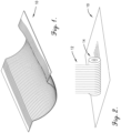
FIG. 1 is a fragmentary perspective view of an exemplary contoured surface of a tool for creating a composite part; -
FIG. 2 is a fragmentary perspective view of a portion of an exemplary automated fiber placement machine laying down fibers on the exemplary surface of the tool ofFIG. 1 , wherein the automated fiber placement machine includes a roller; -
FIG. 3 is an isometric view of an embodiment of a roller device which may be used with the machine ofFIG. 2 ; -
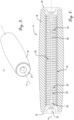
FIG. 4 is a cross-sectional elevation view of the roller device ofFIG. 3 ; -
FIG. 5 is a cross-sectional elevation view of the roller device ofFIG. 3 , wherein the roller device is shown bending to conform to a contour; -
FIG. 6 is an exploded isometric view of certain components of the roller device ofFIG. 3 ; and -
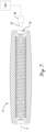
FIG. 7 is a cross-sectional elevation view of an implementation of the roller device which is automatically adjustable. - The figures are not intended to limit the present invention to the specific embodiments they depict. The drawings are not necessarily to scale.
- The following detailed description of embodiments of the invention references the accompanying figures. The embodiments are intended to describe aspects of the invention in sufficient detail to enable those with ordinary skill in the art to practice the invention. The embodiments of the invention are illustrated by way of example and not by way of limitation. Other embodiments may be utilized and changes may be made without departing from the scope of the claims. The following description is, therefore, not limiting. The scope of the present invention is defined only by the appended claims.
- In this description, references to "one embodiment," "an embodiment," or "embodiments" mean that the feature or features referred to are included in at least one embodiment of the invention. Separate references to "one embodiment," "an embodiment," or "embodiments" in this description do not necessarily refer to the same embodiment and are not mutually exclusive unless so stated. Specifically, a feature, component, action, step, etc. described in one embodiment may also be included in other embodiments, but is not necessarily included. Thus, particular implementations of the present invention can include a variety of combinations and/or integrations of the embodiments described herein.
- Broadly characterized, embodiments concern a compliable roller device for use in an automated fiber placement process for creating composite parts on a contoured tool, with the roller device employing a helical spring as an axle to provide more uniform application pressure over a range of tool contours and force levels. Embodiments advantageously avoid the complexity and other limitations of multiple or segmented roller approaches while providing a greater ability to conform to varying contours with more uniform pressure.
- Referring to
FIG. 1 , an exemplary contoured surface of atool 10 is shown for creating composite parts. The composite parts may be, for example, panels or other parts used in the construction of aircraft or other vehicles, and thetool 10 may be of generally conventional design and construction for such purposes. Referring also toFIG. 2 , a portion of an exemplary automated fiber placement machine is shown for laying downfibers 12 on the surface of thetool 10. The automated fiber placement machine may include aroller device 14. - Referring to
FIGs. 3-6 , an embodiment of theroller device 14 includes ahelical spring axle 16, aroller cover 18, atension mechanism 20, and first and second end caps 22,24. Thehelical spring 16 includes multiple turns of a spring material arranged substantially cylindrically along a centerline axis A, and is configured to function as a bendable axle. In a free state, adjacent turns of thehelical spring axle 16 may be in contact with or at least relatively close to one another. Employing thehelical spring 16 as an axle allows theoverall roller device 14 to more easily flex and follow, or comply with, the contours of thetool 10. Theroller cover 18 is a hollow cylinder of rubber or a similarly relatively soft or conformable natural or synthetic material, and is configured to fit over and receive thehelical spring axle 16 within its hollow interior. The thickness of theroller cover 18 may vary over its length, and in one implementation, theroller cover 18 may be relatively thicker at its center than at its ends. - The
tension mechanism 20 may be arranged through the center of or at least generally centrally through thehelical spring axle 16 along the centerline axis A, and may be adjustable to increase or decrease the bendability of thehelical spring axle 16 as desired or needed. As thehelical spring axle 16 bends, portions of the turns on the inner radius or compression side of the bend are unable to move any closer to each other because they are already in or quickly come into contact. However, portions of the turns on the outer radius or tension side of the bend are able to separate from each other. Thus, as thehelical spring axle 16 bends to match a particular contour of thetool 10, the distance along the centerline axis A from one end of thehelical spring axle 16 to the other end must increase. Thetension mechanism 20 is adjustable to a particular length to prevent thehelical spring axle 16 from lengthening beyond a pre-determined length value that corresponds to a desired bend radius of theroller device 10 in order to conform to the contours of thetool 10. The first and second end caps 22,24 may maintain thetension mechanism 20 or at least a portion thereof centered in or at least generally centrally within thehelical spring axle 16. Further, additional end or intermediate bushings orspacers 26 may be used to further maintain thetension mechanism 20 or at least a portion thereof centered in or at least generally centrally within thehelical spring axle 16. - In one implementation, the
tension mechanism 20 may take the form of acable 28 having a threadedportion 30 at one or both ends. Ascrew 32 may be screwed into each threadedportion 30 of thecable 28, and turning thescrew 32 may vary the effective length of thecable 28, and thereby vary the degree of bending of thehelical spring axle 16 that is possible without landing on thescrew 32 and preventing further bending. However, it will be understood that thetension mechanism 20 may take substantially any suitable form for accomplishing the intended function. - In one implementation, the
tension mechanism 20 may be manually adjustable by manually turning thescrews 32 to accommodate different contours. However, repeatedly manually adjusting thetension mechanism 20 may require repeatedly stopping the process to perform the adjustments, so in an additional or alternative implementation, shown inFIG. 7 , thetension mechanism 20 may be automatically adjustable. In this implementation, theroller device 14 may further include anactuator 34 driven by aservo motor 36 for performing the adjustment, and may further include anelectronic controller 38 for controlling theservo motor 36. The electronic controller may be programmed to automatically adjust based on known contours of the tool, or the electronic controller may be programmed to sense contours and automatically adjust in response to the sensed contours of the tool. In this manner, thetension mechanism 20 may be quickly and/or continuously adjusted as needed to accommodate changing contours during the AFP process, thereby avoiding periodic interruptions of the process for manual adjustments. Thus, thetension mechanism 20 may be adjustable manually, semi-manually with themotor 36 controlled by a user, or automatically with themotor 36 controlled by theelectronic controller 38. - Although the invention has been described with reference to the one or more embodiments illustrated in the figures, it is understood that equivalents may be employed and substitutions made herein without departing from the scope of the invention as recited in the claims.
- Having thus described one or more embodiments of the invention, what is claimed as new and desired to be protected by Letters Patent includes the following:
Claims (13)
- A roller device (14) for use in an automated fiber placement process involving a tool (10) having a contour, the roller device comprising:- a helical spring axle (16) having a plurality of turns of a spring material arranged substantially cylindrically along a centerline axis (A), and configured to function as a bendable axle;- a roller cover (18) of a conformable natural or synthetic material, having a hollow interior, and configured to receive the helical spring axle within the hollow interior; and- a tension mechanism (20) arranged through the helical spring axle along the centerline axis, and wherein the tension mechanism is adjustable to a particular length to prevent the helical spring axle from lengthening beyond a particular length value that corresponds to a particular bend radius for conforming to the contour of the tool, to control a bendability of the bendable axle.
- The roller device (14) of claim 1, wherein the roller cover (18) has a length and a thickness, and the thickness varies over the length.
- The roller device (14) of claim 2, wherein the thickness is greater at a center of the length than at an end of the length.
- The roller device (14) of any preceding claim, wherein the tension mechanism (20) includes:- a cable (28) extending through the helical spring axle (16);- a threaded portion (30) at an end of the cable; and- a screw (32) received within the threaded portion and turnable to adjust a length of the cable and thereby adjust the bendability of the bendable axle.
- The roller device (14) of claim 4, further including first and second end caps (22, 24) configured to maintain the cable (28) centrally within the helical spring axle (16).
- The roller device (14) of claim 5, further including one or more additional spacers (26) configured to maintain one or more intermediate portions of the cable (28) centrally within the helical spring axle (16).
- The roller device (14) of claim 1, further including:- an actuator (34);- a servo motor (36) configured to actuate the actuator; and- an electronic controller (38) configured to control the servo motor and actuation of the actuator and thereby automatically adjust the tension mechanism as the roller device moves over the tool (10).
- The roller device (14) of claim 1, wherein the roller cover (18) has a length and a thickness, and the thickness varies over the length, and the thickness of the roller cover is greater at a center of the length than at an end of the length; and the roller device further including:- an actuator (34) coupled with the screw (32);- a servo motor (36) configured to actuate the actuator; and- an electronic controller (38) configured to control the servo motor and actuation of the actuator and thereby automatically turn the screw as the roller device moves over the tool (10).
- The roller device (14) of claim 8, wherein the tension mechanism (20) includes the actuator (34), servo motor (36) and electronic controller (38); and first and second end caps (22, 24) configured to maintain the cable (32) centrally within the helical spring axle (16), and one or more additional spacers (26) configured to maintain one or more intermediate portions of the cable centrally within the helical spring axle.
- The roller device (14) of any one of claims 1 to 6, wherein the tension mechanism (20) is manually adjustable as the roller device moves over the tool (10).
- The roller device (14) of any one of claims 1 to 6, wherein the tension mechanism (20) includes a motor (36), and the tension mechanism is semi-manually adjustable using the motor.
- The roller device (14) of claim 4, wherein the screw (32) is manually turnable.
- The roller device (14) of claim 1, wherein the tension mechanism (20) is automatically adjustable as the roller device moves over the tool (10).
Applications Claiming Priority (1)
| Application Number | Priority Date | Filing Date | Title |
|---|---|---|---|
| US15/878,736 US10926491B2 (en) | 2018-01-24 | 2018-01-24 | Roller device with tailorable compliance for automated fiber placement |
Publications (3)
| Publication Number | Publication Date |
|---|---|
| EP3517280A1 EP3517280A1 (en) | 2019-07-31 |
| EP3517280B1 true EP3517280B1 (en) | 2024-07-17 |
| EP3517280C0 EP3517280C0 (en) | 2024-07-17 |
Family
ID=65138816
Family Applications (1)
| Application Number | Title | Priority Date | Filing Date |
|---|---|---|---|
| EP19152492.5A Active EP3517280B1 (en) | 2018-01-24 | 2019-01-18 | Roller device with tailorable compliance for automated fiber placement |
Country Status (4)
| Country | Link |
|---|---|
| US (1) | US10926491B2 (en) |
| EP (1) | EP3517280B1 (en) |
| CN (1) | CN110065244B (en) |
| ES (1) | ES2984184T3 (en) |
Families Citing this family (9)
| Publication number | Priority date | Publication date | Assignee | Title |
|---|---|---|---|---|
| CN114179397B (en) * | 2021-11-26 | 2022-09-27 | 公元管道(安徽)有限公司 | Continuous fiber plastic-coated mould |
| CN115782227B (en) * | 2022-12-28 | 2026-01-30 | 江西水利电力大学 | A deformable automatic yarn-laying pressure roller mechanism |
| CN116161472B (en) * | 2022-12-30 | 2025-10-21 | 南京航空航天大学无锡研究院 | Large-width braided belt spreading device and method |
| CN116039125B (en) * | 2022-12-30 | 2025-07-08 | 南京航空航天大学无锡研究院 | Large-width high-flexibility compression roller device |
| CN116551889A (en) * | 2023-07-11 | 2023-08-08 | 山东中恒景新碳纤维科技发展有限公司 | Fiber prepreg paving method |
| US12491689B2 (en) * | 2023-08-28 | 2025-12-09 | Northrop Grumman Systems Corporation | Lay-up forming device and associated components and methods |
| CN117400562B (en) * | 2023-10-09 | 2026-03-24 | 航天特种材料及工艺技术研究所 | A variable width automatic yarn-laying roller suitable for yarn-laying |
| US12365149B1 (en) | 2024-03-18 | 2025-07-22 | General Electric Company | Automated fiber placement assembly with pressure roller |
| CN121403741B (en) * | 2025-12-26 | 2026-04-07 | 浙江博高机电科技有限公司 | Winding device for fiber tow reinforcing layer of composite pipeline |
Citations (1)
| Publication number | Priority date | Publication date | Assignee | Title |
|---|---|---|---|---|
| US4997510A (en) * | 1988-03-28 | 1991-03-05 | Shinnippon Koki Kabushiki Kaisha (Shinnippon Koki Co., Ltd.) | Automatic tape affixing apparatus |
Family Cites Families (30)
| Publication number | Priority date | Publication date | Assignee | Title |
|---|---|---|---|---|
| US1271194A (en) | 1917-11-26 | 1918-07-02 | Peter Meyer | Spring-roll. |
| US1768044A (en) * | 1926-03-12 | 1930-06-24 | Blaw Knox Co | Flexible roller |
| US2367088A (en) * | 1942-03-21 | 1945-01-09 | S K F Ind Inc | Top roll assembly |
| US3091990A (en) * | 1960-03-24 | 1963-06-04 | Harland E Mcvittie | Hollow tubular spirally wound covered metallic anchor |
| US3467450A (en) * | 1967-12-14 | 1969-09-16 | Roller Bearing Co Of America | Eccentrically adjustable roller |
| US3603416A (en) * | 1970-05-18 | 1971-09-07 | Fmc Corp | Weighing apparatus for belt conveyor |
| US3853170A (en) * | 1971-10-13 | 1974-12-10 | B Barettella | Shade roller apparatus |
| US3832749A (en) * | 1973-01-05 | 1974-09-03 | Harding Dev Co | Self-standing paint roller |
| JPS5832707B2 (en) * | 1977-06-10 | 1983-07-14 | キヤノン株式会社 | elastic roller |
| US4571832A (en) * | 1982-09-24 | 1986-02-25 | John Hendy | Melon-slicing apparatus with adjustable guide roller |
| US4460433A (en) | 1982-11-04 | 1984-07-17 | Boyd Walter K | Pressure roller for roofing machines |
| FR2650529B1 (en) * | 1989-08-03 | 1991-11-08 | Aerospatiale | APPLICATOR DEVICE FOR TAPERING MACHINE USING COMPOSITE MATERIAL TAPE |
| US5251986A (en) * | 1992-08-10 | 1993-10-12 | Grumman Aerospace Corporation | Bushing assembly |
| US5395447A (en) * | 1993-11-03 | 1995-03-07 | Wu; Ching C. | Adjustable double-roller oil feeder |
| US6637827B2 (en) * | 2000-02-28 | 2003-10-28 | Myron Stuart Hurwitz | Generation of in-line skates and skate-boards wtih safety “edging friction control™” |
| US20030136643A1 (en) * | 2002-01-18 | 2003-07-24 | Lockheed Martin Corporation | Dynamically variable diameter, drive roller mounting system for companioned-belt speed synchronization, and a method of operating the same |
| US7100238B2 (en) * | 2003-11-14 | 2006-09-05 | Mccauley Patrick | Bendable extension arm |
| DE102005044956A1 (en) * | 2005-09-20 | 2007-03-22 | Voith Patent Gmbh | Spreader roll |
| US8042594B2 (en) * | 2006-06-28 | 2011-10-25 | Alliant Techsystems Inc. | Compaction device for fiber placement using interdependent segment travel |
| DE202006019824U1 (en) * | 2006-09-25 | 2007-05-10 | Bos Gmbh & Co. Kg | Roller arrangement for use in vehicle, has damping profile designed in such a manner that it lies at inner side of winding spring with outer contact sections and at outer side of spring rod with inner contact sections |
| DK2337670T3 (en) | 2008-09-18 | 2019-07-22 | Fraunhofer Ges Forschung | Method and apparatus for manufacturing composite material components and printing unit |
| FR2948058B1 (en) * | 2009-07-17 | 2011-07-22 | Coriolis Composites | FIBER APPLICATION MACHINE COMPRISING A FLEXIBLE COMPACTION ROLL WITH THERMAL CONTROL SYSTEM |
| DE102010013711A1 (en) * | 2010-04-02 | 2011-10-06 | Airbus Operations Gmbh | Pressure roller unit for depositing pre-impregnated slivers on a surface and depositing device |
| WO2012015386A1 (en) * | 2010-07-26 | 2012-02-02 | Planetair Turf Products, Llc | Systems and methods for treating a ground surface |
| US8449683B2 (en) * | 2010-12-10 | 2013-05-28 | Marilyn S. Vice | Apparatus and method for picking up stickers in grassy and other areas |
| FR2975334B1 (en) * | 2011-05-20 | 2016-04-15 | Coriolis Composites Attn Olivier Bouroullec | FIBER APPLICATION HEAD WITH SEGMENTED COMPACTION ROLL |
| JP6238678B2 (en) * | 2013-10-18 | 2017-11-29 | 株式会社市川鉄工 | Yarn supply device for torsion lace machine |
| US9889610B2 (en) * | 2014-07-29 | 2018-02-13 | The Boeing Company | Automated ply forming and compaction using flexible roller contact |
| US9073198B1 (en) * | 2014-09-23 | 2015-07-07 | Marvin L. Menius | Flexible utility handle |
| US10393206B2 (en) * | 2017-05-16 | 2019-08-27 | Chih-Yung Wang | Buffer device for small-sized roller shade |
-
2018
- 2018-01-24 US US15/878,736 patent/US10926491B2/en not_active Expired - Fee Related
-
2019
- 2019-01-18 EP EP19152492.5A patent/EP3517280B1/en active Active
- 2019-01-18 ES ES19152492T patent/ES2984184T3/en active Active
- 2019-01-22 CN CN201910060782.0A patent/CN110065244B/en not_active Expired - Fee Related
Patent Citations (1)
| Publication number | Priority date | Publication date | Assignee | Title |
|---|---|---|---|---|
| US4997510A (en) * | 1988-03-28 | 1991-03-05 | Shinnippon Koki Kabushiki Kaisha (Shinnippon Koki Co., Ltd.) | Automatic tape affixing apparatus |
Also Published As
| Publication number | Publication date |
|---|---|
| CN110065244B (en) | 2022-09-20 |
| US10926491B2 (en) | 2021-02-23 |
| CN110065244A (en) | 2019-07-30 |
| US20190224927A1 (en) | 2019-07-25 |
| ES2984184T3 (en) | 2024-10-29 |
| EP3517280A1 (en) | 2019-07-31 |
| EP3517280C0 (en) | 2024-07-17 |
Similar Documents
| Publication | Publication Date | Title |
|---|---|---|
| US10926491B2 (en) | Roller device with tailorable compliance for automated fiber placement | |
| US8839837B2 (en) | Device and method for optical cable installation | |
| DE102007013902A1 (en) | Device for profile bending | |
| US5176785A (en) | Applicator device for a laying machine using a composite material tape | |
| US5122006A (en) | Trowelling bar arching adjustment apparatus | |
| JPH02243452A (en) | Width extension roll | |
| US7338270B2 (en) | Guide device for use with flat box device in applying drywall mastic | |
| EP1695774B1 (en) | Manufacturing apparatus adapted to stretch a shape memory alloy and manufacturing method | |
| US20210402728A1 (en) | System for producing lengths of tube comprising helically wound strips | |
| US20160141855A1 (en) | Strain Relief Device for a Harness or Cable | |
| JPS6218434Y2 (en) | ||
| WO2012112875A2 (en) | Optical fiber cable assembly | |
| DE102018103347B4 (en) | Apparatus and method for wrapping a pipe | |
| KR200372927Y1 (en) | Do spiral spring manufactory | |
| CN104743405A (en) | Optical fiber winding device | |
| US2956754A (en) | Comb winding guide | |
| JP6267891B2 (en) | Long object gripping apparatus and long object gripping method | |
| JP5211709B2 (en) | Wire tensioning device | |
| EP1279635B1 (en) | Apparatus for winding a profiled strip on a bobbin | |
| EP3711937B1 (en) | Tyre assembly system and method for winding tyre components | |
| US6959849B2 (en) | Drive roller assembly | |
| JP2001086616A (en) | Cable core cutting equipment | |
| ITMI991268A1 (en) | PULL AND PUSH COMMAND DEVICE TO ARTICULATED ELEMENTS | |
| KR101256515B1 (en) | Roll having function for anti-snaking | |
| CN217798669U (en) | Wire forming jig |
Legal Events
| Date | Code | Title | Description |
|---|---|---|---|
| PUAI | Public reference made under article 153(3) epc to a published international application that has entered the european phase |
Free format text: ORIGINAL CODE: 0009012 |
|
| STAA | Information on the status of an ep patent application or granted ep patent |
Free format text: STATUS: THE APPLICATION HAS BEEN PUBLISHED |
|
| AK | Designated contracting states |
Kind code of ref document: A1 Designated state(s): AL AT BE BG CH CY CZ DE DK EE ES FI FR GB GR HR HU IE IS IT LI LT LU LV MC MK MT NL NO PL PT RO RS SE SI SK SM TR |
|
| AX | Request for extension of the european patent |
Extension state: BA ME |
|
| STAA | Information on the status of an ep patent application or granted ep patent |
Free format text: STATUS: REQUEST FOR EXAMINATION WAS MADE |
|
| 17P | Request for examination filed |
Effective date: 20200123 |
|
| RBV | Designated contracting states (corrected) |
Designated state(s): AL AT BE BG CH CY CZ DE DK EE ES FI FR GB GR HR HU IE IS IT LI LT LU LV MC MK MT NL NO PL PT RO RS SE SI SK SM TR |
|
| STAA | Information on the status of an ep patent application or granted ep patent |
Free format text: STATUS: EXAMINATION IS IN PROGRESS |
|
| 17Q | First examination report despatched |
Effective date: 20220322 |
|
| GRAP | Despatch of communication of intention to grant a patent |
Free format text: ORIGINAL CODE: EPIDOSNIGR1 |
|
| STAA | Information on the status of an ep patent application or granted ep patent |
Free format text: STATUS: GRANT OF PATENT IS INTENDED |
|
| INTG | Intention to grant announced |
Effective date: 20240229 |
|
| GRAS | Grant fee paid |
Free format text: ORIGINAL CODE: EPIDOSNIGR3 |
|
| GRAA | (expected) grant |
Free format text: ORIGINAL CODE: 0009210 |
|
| STAA | Information on the status of an ep patent application or granted ep patent |
Free format text: STATUS: THE PATENT HAS BEEN GRANTED |
|
| AK | Designated contracting states |
Kind code of ref document: B1 Designated state(s): AL AT BE BG CH CY CZ DE DK EE ES FI FR GB GR HR HU IE IS IT LI LT LU LV MC MK MT NL NO PL PT RO RS SE SI SK SM TR |
|
| REG | Reference to a national code |
Ref country code: CH Ref legal event code: EP |
|
| REG | Reference to a national code |
Ref country code: DE Ref legal event code: R096 Ref document number: 602019055241 Country of ref document: DE |
|
| REG | Reference to a national code |
Ref country code: IE Ref legal event code: FG4D |
|
| U01 | Request for unitary effect filed |
Effective date: 20240805 |
|
| U07 | Unitary effect registered |
Designated state(s): AT BE BG DE DK EE FI FR IT LT LU LV MT NL PT SE SI Effective date: 20240820 |
|
| REG | Reference to a national code |
Ref country code: ES Ref legal event code: FG2A Ref document number: 2984184 Country of ref document: ES Kind code of ref document: T3 Effective date: 20241029 |
|
| U20 | Renewal fee for the european patent with unitary effect paid |
Year of fee payment: 7 Effective date: 20241118 |
|
| PG25 | Lapsed in a contracting state [announced via postgrant information from national office to epo] |
Ref country code: NO Free format text: LAPSE BECAUSE OF FAILURE TO SUBMIT A TRANSLATION OF THE DESCRIPTION OR TO PAY THE FEE WITHIN THE PRESCRIBED TIME-LIMIT Effective date: 20241017 |
|
| PG25 | Lapsed in a contracting state [announced via postgrant information from national office to epo] |
Ref country code: GR Free format text: LAPSE BECAUSE OF FAILURE TO SUBMIT A TRANSLATION OF THE DESCRIPTION OR TO PAY THE FEE WITHIN THE PRESCRIBED TIME-LIMIT Effective date: 20241018 Ref country code: PL Free format text: LAPSE BECAUSE OF FAILURE TO SUBMIT A TRANSLATION OF THE DESCRIPTION OR TO PAY THE FEE WITHIN THE PRESCRIBED TIME-LIMIT Effective date: 20240717 |
|
| PGFP | Annual fee paid to national office [announced via postgrant information from national office to epo] |
Ref country code: GB Payment date: 20241119 Year of fee payment: 7 |
|
| PG25 | Lapsed in a contracting state [announced via postgrant information from national office to epo] |
Ref country code: IS Free format text: LAPSE BECAUSE OF FAILURE TO SUBMIT A TRANSLATION OF THE DESCRIPTION OR TO PAY THE FEE WITHIN THE PRESCRIBED TIME-LIMIT Effective date: 20241117 |
|
| PG25 | Lapsed in a contracting state [announced via postgrant information from national office to epo] |
Ref country code: HR Free format text: LAPSE BECAUSE OF FAILURE TO SUBMIT A TRANSLATION OF THE DESCRIPTION OR TO PAY THE FEE WITHIN THE PRESCRIBED TIME-LIMIT Effective date: 20240717 |
|
| PG25 | Lapsed in a contracting state [announced via postgrant information from national office to epo] |
Ref country code: RS Free format text: LAPSE BECAUSE OF FAILURE TO SUBMIT A TRANSLATION OF THE DESCRIPTION OR TO PAY THE FEE WITHIN THE PRESCRIBED TIME-LIMIT Effective date: 20241017 |
|
| PG25 | Lapsed in a contracting state [announced via postgrant information from national office to epo] |
Ref country code: RS Free format text: LAPSE BECAUSE OF FAILURE TO SUBMIT A TRANSLATION OF THE DESCRIPTION OR TO PAY THE FEE WITHIN THE PRESCRIBED TIME-LIMIT Effective date: 20241017 Ref country code: PL Free format text: LAPSE BECAUSE OF FAILURE TO SUBMIT A TRANSLATION OF THE DESCRIPTION OR TO PAY THE FEE WITHIN THE PRESCRIBED TIME-LIMIT Effective date: 20240717 Ref country code: NO Free format text: LAPSE BECAUSE OF FAILURE TO SUBMIT A TRANSLATION OF THE DESCRIPTION OR TO PAY THE FEE WITHIN THE PRESCRIBED TIME-LIMIT Effective date: 20241017 Ref country code: IS Free format text: LAPSE BECAUSE OF FAILURE TO SUBMIT A TRANSLATION OF THE DESCRIPTION OR TO PAY THE FEE WITHIN THE PRESCRIBED TIME-LIMIT Effective date: 20241117 Ref country code: HR Free format text: LAPSE BECAUSE OF FAILURE TO SUBMIT A TRANSLATION OF THE DESCRIPTION OR TO PAY THE FEE WITHIN THE PRESCRIBED TIME-LIMIT Effective date: 20240717 Ref country code: GR Free format text: LAPSE BECAUSE OF FAILURE TO SUBMIT A TRANSLATION OF THE DESCRIPTION OR TO PAY THE FEE WITHIN THE PRESCRIBED TIME-LIMIT Effective date: 20241018 |
|
| PG25 | Lapsed in a contracting state [announced via postgrant information from national office to epo] |
Ref country code: SM Free format text: LAPSE BECAUSE OF FAILURE TO SUBMIT A TRANSLATION OF THE DESCRIPTION OR TO PAY THE FEE WITHIN THE PRESCRIBED TIME-LIMIT Effective date: 20240717 |
|
| PG25 | Lapsed in a contracting state [announced via postgrant information from national office to epo] |
Ref country code: CZ Free format text: LAPSE BECAUSE OF FAILURE TO SUBMIT A TRANSLATION OF THE DESCRIPTION OR TO PAY THE FEE WITHIN THE PRESCRIBED TIME-LIMIT Effective date: 20240717 |
|
| PG25 | Lapsed in a contracting state [announced via postgrant information from national office to epo] |
Ref country code: SK Free format text: LAPSE BECAUSE OF FAILURE TO SUBMIT A TRANSLATION OF THE DESCRIPTION OR TO PAY THE FEE WITHIN THE PRESCRIBED TIME-LIMIT Effective date: 20240717 |
|
| PLBE | No opposition filed within time limit |
Free format text: ORIGINAL CODE: 0009261 |
|
| STAA | Information on the status of an ep patent application or granted ep patent |
Free format text: STATUS: NO OPPOSITION FILED WITHIN TIME LIMIT |
|
| 26N | No opposition filed |
Effective date: 20250422 |
|
| REG | Reference to a national code |
Ref country code: CH Ref legal event code: PL |
|
| PG25 | Lapsed in a contracting state [announced via postgrant information from national office to epo] |
Ref country code: MC Free format text: LAPSE BECAUSE OF FAILURE TO SUBMIT A TRANSLATION OF THE DESCRIPTION OR TO PAY THE FEE WITHIN THE PRESCRIBED TIME-LIMIT Effective date: 20240717 |
|
| PG25 | Lapsed in a contracting state [announced via postgrant information from national office to epo] |
Ref country code: CH Free format text: LAPSE BECAUSE OF NON-PAYMENT OF DUE FEES Effective date: 20250131 |
|
| PG25 | Lapsed in a contracting state [announced via postgrant information from national office to epo] |
Ref country code: IE Free format text: LAPSE BECAUSE OF NON-PAYMENT OF DUE FEES Effective date: 20250118 |
|
| REG | Reference to a national code |
Ref country code: ES Ref legal event code: FD2A Effective date: 20260227 |
|
| PG25 | Lapsed in a contracting state [announced via postgrant information from national office to epo] |
Ref country code: ES Free format text: LAPSE BECAUSE OF NON-PAYMENT OF DUE FEES Effective date: 20250119 |
|
| PG25 | Lapsed in a contracting state [announced via postgrant information from national office to epo] |
Ref country code: RO Free format text: LAPSE BECAUSE OF FAILURE TO SUBMIT A TRANSLATION OF THE DESCRIPTION OR TO PAY THE FEE WITHIN THE PRESCRIBED TIME-LIMIT Effective date: 20240717 |