EP3517221A1 - Mixing device and applicator for sealants - Google Patents
Mixing device and applicator for sealants Download PDFInfo
- Publication number
- EP3517221A1 EP3517221A1 EP17852467.4A EP17852467A EP3517221A1 EP 3517221 A1 EP3517221 A1 EP 3517221A1 EP 17852467 A EP17852467 A EP 17852467A EP 3517221 A1 EP3517221 A1 EP 3517221A1
- Authority
- EP
- European Patent Office
- Prior art keywords
- applicator
- mixing device
- cylinder
- sealants according
- sealants
- Prior art date
- Legal status (The legal status is an assumption and is not a legal conclusion. Google has not performed a legal analysis and makes no representation as to the accuracy of the status listed.)
- Granted
Links
- 239000000565 sealant Substances 0.000 title claims abstract description 19
- 239000012812 sealant material Substances 0.000 claims abstract description 10
- 230000008878 coupling Effects 0.000 claims description 2
- 238000010168 coupling process Methods 0.000 claims description 2
- 238000005859 coupling reaction Methods 0.000 claims description 2
- 230000007704 transition Effects 0.000 claims description 2
- 230000009471 action Effects 0.000 abstract description 15
- 239000000463 material Substances 0.000 abstract description 11
- 230000007246 mechanism Effects 0.000 abstract description 3
- 150000001875 compounds Chemical class 0.000 description 4
- 238000004873 anchoring Methods 0.000 description 3
- 230000014759 maintenance of location Effects 0.000 description 3
- 239000000203 mixture Substances 0.000 description 3
- 238000007789 sealing Methods 0.000 description 3
- 230000001105 regulatory effect Effects 0.000 description 2
- 230000000284 resting effect Effects 0.000 description 2
- 239000000126 substance Substances 0.000 description 2
- 238000007792 addition Methods 0.000 description 1
- 230000033228 biological regulation Effects 0.000 description 1
- 230000005540 biological transmission Effects 0.000 description 1
- 230000001419 dependent effect Effects 0.000 description 1
- 239000003566 sealing material Substances 0.000 description 1
Images
Classifications
-
- B—PERFORMING OPERATIONS; TRANSPORTING
- B05—SPRAYING OR ATOMISING IN GENERAL; APPLYING FLUENT MATERIALS TO SURFACES, IN GENERAL
- B05C—APPARATUS FOR APPLYING FLUENT MATERIALS TO SURFACES, IN GENERAL
- B05C17/00—Hand tools or apparatus using hand held tools, for applying liquids or other fluent materials to, for spreading applied liquids or other fluent materials on, or for partially removing applied liquids or other fluent materials from, surfaces
- B05C17/005—Hand tools or apparatus using hand held tools, for applying liquids or other fluent materials to, for spreading applied liquids or other fluent materials on, or for partially removing applied liquids or other fluent materials from, surfaces for discharging material from a reservoir or container located in or on the hand tool through an outlet orifice by pressure without using surface contacting members like pads or brushes
- B05C17/01—Hand tools or apparatus using hand held tools, for applying liquids or other fluent materials to, for spreading applied liquids or other fluent materials on, or for partially removing applied liquids or other fluent materials from, surfaces for discharging material from a reservoir or container located in or on the hand tool through an outlet orifice by pressure without using surface contacting members like pads or brushes with manually mechanically or electrically actuated piston or the like
-
- B—PERFORMING OPERATIONS; TRANSPORTING
- B05—SPRAYING OR ATOMISING IN GENERAL; APPLYING FLUENT MATERIALS TO SURFACES, IN GENERAL
- B05C—APPARATUS FOR APPLYING FLUENT MATERIALS TO SURFACES, IN GENERAL
- B05C17/00—Hand tools or apparatus using hand held tools, for applying liquids or other fluent materials to, for spreading applied liquids or other fluent materials on, or for partially removing applied liquids or other fluent materials from, surfaces
- B05C17/005—Hand tools or apparatus using hand held tools, for applying liquids or other fluent materials to, for spreading applied liquids or other fluent materials on, or for partially removing applied liquids or other fluent materials from, surfaces for discharging material from a reservoir or container located in or on the hand tool through an outlet orifice by pressure without using surface contacting members like pads or brushes
- B05C17/01—Hand tools or apparatus using hand held tools, for applying liquids or other fluent materials to, for spreading applied liquids or other fluent materials on, or for partially removing applied liquids or other fluent materials from, surfaces for discharging material from a reservoir or container located in or on the hand tool through an outlet orifice by pressure without using surface contacting members like pads or brushes with manually mechanically or electrically actuated piston or the like
- B05C17/0103—Hand tools or apparatus using hand held tools, for applying liquids or other fluent materials to, for spreading applied liquids or other fluent materials on, or for partially removing applied liquids or other fluent materials from, surfaces for discharging material from a reservoir or container located in or on the hand tool through an outlet orifice by pressure without using surface contacting members like pads or brushes with manually mechanically or electrically actuated piston or the like with electrically actuated piston or the like
-
- B—PERFORMING OPERATIONS; TRANSPORTING
- B01—PHYSICAL OR CHEMICAL PROCESSES OR APPARATUS IN GENERAL
- B01F—MIXING, e.g. DISSOLVING, EMULSIFYING OR DISPERSING
- B01F29/00—Mixers with rotating receptacles
- B01F29/60—Mixers with rotating receptacles rotating about a horizontal or inclined axis, e.g. drum mixers
-
- B—PERFORMING OPERATIONS; TRANSPORTING
- B01—PHYSICAL OR CHEMICAL PROCESSES OR APPARATUS IN GENERAL
- B01F—MIXING, e.g. DISSOLVING, EMULSIFYING OR DISPERSING
- B01F35/00—Accessories for mixers; Auxiliary operations or auxiliary devices; Parts or details of general application
- B01F35/71—Feed mechanisms
- B01F35/717—Feed mechanisms characterised by the means for feeding the components to the mixer
-
- B—PERFORMING OPERATIONS; TRANSPORTING
- B01—PHYSICAL OR CHEMICAL PROCESSES OR APPARATUS IN GENERAL
- B01F—MIXING, e.g. DISSOLVING, EMULSIFYING OR DISPERSING
- B01F35/00—Accessories for mixers; Auxiliary operations or auxiliary devices; Parts or details of general application
- B01F35/75—Discharge mechanisms
- B01F35/754—Discharge mechanisms characterised by the means for discharging the components from the mixer
- B01F35/75425—Discharge mechanisms characterised by the means for discharging the components from the mixer using pistons or plungers
-
- B—PERFORMING OPERATIONS; TRANSPORTING
- B05—SPRAYING OR ATOMISING IN GENERAL; APPLYING FLUENT MATERIALS TO SURFACES, IN GENERAL
- B05C—APPARATUS FOR APPLYING FLUENT MATERIALS TO SURFACES, IN GENERAL
- B05C17/00—Hand tools or apparatus using hand held tools, for applying liquids or other fluent materials to, for spreading applied liquids or other fluent materials on, or for partially removing applied liquids or other fluent materials from, surfaces
- B05C17/005—Hand tools or apparatus using hand held tools, for applying liquids or other fluent materials to, for spreading applied liquids or other fluent materials on, or for partially removing applied liquids or other fluent materials from, surfaces for discharging material from a reservoir or container located in or on the hand tool through an outlet orifice by pressure without using surface contacting members like pads or brushes
-
- B—PERFORMING OPERATIONS; TRANSPORTING
- B05—SPRAYING OR ATOMISING IN GENERAL; APPLYING FLUENT MATERIALS TO SURFACES, IN GENERAL
- B05C—APPARATUS FOR APPLYING FLUENT MATERIALS TO SURFACES, IN GENERAL
- B05C17/00—Hand tools or apparatus using hand held tools, for applying liquids or other fluent materials to, for spreading applied liquids or other fluent materials on, or for partially removing applied liquids or other fluent materials from, surfaces
- B05C17/005—Hand tools or apparatus using hand held tools, for applying liquids or other fluent materials to, for spreading applied liquids or other fluent materials on, or for partially removing applied liquids or other fluent materials from, surfaces for discharging material from a reservoir or container located in or on the hand tool through an outlet orifice by pressure without using surface contacting members like pads or brushes
- B05C17/01—Hand tools or apparatus using hand held tools, for applying liquids or other fluent materials to, for spreading applied liquids or other fluent materials on, or for partially removing applied liquids or other fluent materials from, surfaces for discharging material from a reservoir or container located in or on the hand tool through an outlet orifice by pressure without using surface contacting members like pads or brushes with manually mechanically or electrically actuated piston or the like
- B05C17/0116—Hand tools or apparatus using hand held tools, for applying liquids or other fluent materials to, for spreading applied liquids or other fluent materials on, or for partially removing applied liquids or other fluent materials from, surfaces for discharging material from a reservoir or container located in or on the hand tool through an outlet orifice by pressure without using surface contacting members like pads or brushes with manually mechanically or electrically actuated piston or the like characterised by the piston driving means
- B05C17/0133—Nut and bolt advancing mechanism, e.g. threaded piston rods
-
- B—PERFORMING OPERATIONS; TRANSPORTING
- B01—PHYSICAL OR CHEMICAL PROCESSES OR APPARATUS IN GENERAL
- B01F—MIXING, e.g. DISSOLVING, EMULSIFYING OR DISPERSING
- B01F2101/00—Mixing characterised by the nature of the mixed materials or by the application field
- B01F2101/36—Mixing of ingredients for adhesives or glues; Mixing adhesives and gas
-
- B—PERFORMING OPERATIONS; TRANSPORTING
- B05—SPRAYING OR ATOMISING IN GENERAL; APPLYING FLUENT MATERIALS TO SURFACES, IN GENERAL
- B05C—APPARATUS FOR APPLYING FLUENT MATERIALS TO SURFACES, IN GENERAL
- B05C17/00—Hand tools or apparatus using hand held tools, for applying liquids or other fluent materials to, for spreading applied liquids or other fluent materials on, or for partially removing applied liquids or other fluent materials from, surfaces
- B05C17/005—Hand tools or apparatus using hand held tools, for applying liquids or other fluent materials to, for spreading applied liquids or other fluent materials on, or for partially removing applied liquids or other fluent materials from, surfaces for discharging material from a reservoir or container located in or on the hand tool through an outlet orifice by pressure without using surface contacting members like pads or brushes
- B05C17/00553—Hand tools or apparatus using hand held tools, for applying liquids or other fluent materials to, for spreading applied liquids or other fluent materials on, or for partially removing applied liquids or other fluent materials from, surfaces for discharging material from a reservoir or container located in or on the hand tool through an outlet orifice by pressure without using surface contacting members like pads or brushes with means allowing the stock of material to consist of at least two different components
-
- B—PERFORMING OPERATIONS; TRANSPORTING
- B05—SPRAYING OR ATOMISING IN GENERAL; APPLYING FLUENT MATERIALS TO SURFACES, IN GENERAL
- B05C—APPARATUS FOR APPLYING FLUENT MATERIALS TO SURFACES, IN GENERAL
- B05C17/00—Hand tools or apparatus using hand held tools, for applying liquids or other fluent materials to, for spreading applied liquids or other fluent materials on, or for partially removing applied liquids or other fluent materials from, surfaces
- B05C17/005—Hand tools or apparatus using hand held tools, for applying liquids or other fluent materials to, for spreading applied liquids or other fluent materials on, or for partially removing applied liquids or other fluent materials from, surfaces for discharging material from a reservoir or container located in or on the hand tool through an outlet orifice by pressure without using surface contacting members like pads or brushes
- B05C17/01—Hand tools or apparatus using hand held tools, for applying liquids or other fluent materials to, for spreading applied liquids or other fluent materials on, or for partially removing applied liquids or other fluent materials from, surfaces for discharging material from a reservoir or container located in or on the hand tool through an outlet orifice by pressure without using surface contacting members like pads or brushes with manually mechanically or electrically actuated piston or the like
- B05C17/0113—Hand tools or apparatus using hand held tools, for applying liquids or other fluent materials to, for spreading applied liquids or other fluent materials on, or for partially removing applied liquids or other fluent materials from, surfaces for discharging material from a reservoir or container located in or on the hand tool through an outlet orifice by pressure without using surface contacting members like pads or brushes with manually mechanically or electrically actuated piston or the like the piston rod being flexible or articulated
Definitions
- the disclosed invention falls within the sector of accessories or devices used in the mixing or application of materials which are intended for sealing joints.
- the disclosed invention falls within the sector of devices used with the aforementioned aim, the form of mixing or application of which requires a mechanical action produced in a non-manual way.
- a series of devices which use a mechanical action for the mixing or application thereof.
- the majority of said devices consist of a housing whereon the container rests wherein the material to be applied is housed and the form of application of which is carried out by means of the pressure exerted by a plunger coupled to a guide which is actuated manually by a trigger.
- Both inventions are devices which require actuating means external to them such as a drill or a device comprising a rotor.
- the devices currently existing depend on auxiliary forces for the operation thereof, or rather the force of a person or even the force generated through a drill or device with a rotor that can be coupled to the devices.
- the disclosed invention intends to provide a device which apart from ensuring a correct mixing and application of the compound by means of an ideal regulation pursuant to the conditions recommended by the manufacturers thereof in order to ensure the reliability thereof, performs the mentioned actions in a single device without additions from or dependence on other devices.
- the mixing device and applicator for sealants which, according to the title and in a selectable manner in one action mixes and in another action applies a sealant material, is configured starting from a drill-like or similar appearance comprising a handle wherein a trigger, a speed selector and a rotation changer are arranged.
- a removable sheath is arranged whereon the container of the material to be mixed is introduced, said container acts as a stop on the same, fitting to the sheath by means of the rotation of a head with a retention ring present therein and is coupled to the device by means of an anchoring system with rotation.
- Said coupling is carried out inside a rotating cylinder present in the device and which by means of the actuation of the rotation selector and the trigger present in the handle is rotated in the sense selected for the mixing by means of the action of a rotor present in the rear portion of the device.
- the rotational movement of the cylinder is transferred from the rotor to the same through an adapter formed on one end in a geometric shape with edges and introduced into a cavity with the same geometric shape arranged inside the cylinder.
- the longitudinal retention of the rotating cylinder towards the outside of the device is a consequence of the stop action of a circular protrusion in the outline of the cylinder with an intermediate bearing and this in turn with a closing bushing present in the front portion of the device.
- the name closing bushing comes from it performing the functions of closing the enclosure or casing which covers the mechanisms present in the device.
- the rotation of the cylinder is then locked by means of a manual braking system present in the upper portion of the closing bushing and resting on the anchoring area of the sheath with the cylinder.
- a plunger coupled to a longitudinal telescopic shaft gathered inside the adapter is ejected longitudinally forwards thus proceeding to the ejection of the material to be applied by means of the contact made by the plunger on the piston present inside the container.
- a group of gears with a clutch comprised inside the device is responsible for reducing and adapting the speeds of the rotation and the torque generated by the rotor and transmitted to the cylinder both in the mixing action and in the application action of the sealant material.
- the movement of the rotor presents the possibility of being generated either by means of an electric motor regulated by electronic components housed inside the device or by means of an integrated pneumatic system.
- the use of the device is not discarded for use in the application of other commonly used sealants, the use thereof is intended for the mixing and application of a material, which in particular requires the involvement of the user accompanying the rotations performed by the container in the device during the mixing with longitudinal movements of a piston located in the ejection mouth of the sealant and coupled to a helix present inside the container.
- the mixing device and applicator for sealants comprises a handle (1) which houses a trigger (2), a rotation speed regulator (3) and a rotation sense selector (4).
- a modular casing or enclosure (5) rests on said handle (1) which is closed in the rear portion by means of one of said modules and in the front portion by means of a closing bushing (6) fastened thereto preferably by means of screws.
- a sheath (7) is arranged with a tightening head (8) which is coupled to the device preferably by means of an anchoring system made up of a series of protuberances (9) present therein and introduced through secured tracks (10) existing in the front portion of the device.
- the modular casing or enclosure (5) houses on the inside thereof the mechanisms, transmissions and gears described below;
- Said closing bushing (6) incorporates a system for locking or releasing the rotation of the cylinder preferably made up of a retention rod (19) with a lever head and guiding and closing means (20) thereof.
Landscapes
- Chemical & Material Sciences (AREA)
- Chemical Kinetics & Catalysis (AREA)
- Engineering & Computer Science (AREA)
- Mechanical Engineering (AREA)
- Coating Apparatus (AREA)
Abstract
Description
- The disclosed invention falls within the sector of accessories or devices used in the mixing or application of materials which are intended for sealing joints.
- Further specifying the sector for which it is intended, the disclosed invention falls within the sector of devices used with the aforementioned aim, the form of mixing or application of which requires a mechanical action produced in a non-manual way.
- At the date of completion of the present specification, a variety of systems or devices are known which have the aforementioned aim in the sector of the art carried out in independent devices.
- A series of devices are known which use a mechanical action for the mixing or application thereof. The majority of said devices, independent for each action, consist of a housing whereon the container rests wherein the material to be applied is housed and the form of application of which is carried out by means of the pressure exerted by a plunger coupled to a guide which is actuated manually by a trigger.
- Devices are also known which are solely intended for the mixing of two or more components.
- The same holder of the present invention is in turn the holder of two inventions which are similar in principle and which are explained below;
-
WO2014198966 titled Device for mixing and applying a compound produced by mixing two products. It describes a device made up of a rotating casing with locking means wherein it houses the container with the material to be applied, a mobile plunger with the actuating means thereof and means for fixing the entire assembly to a drill or similar. -
ES2578808 - Both inventions are devices which require actuating means external to them such as a drill or a device comprising a rotor.
- Although it is true that said devices are related in principle and are similar to a certain degree to the one disclosed herein, the similarity of these as far as the form of embodiment relates, they differ in a relevant manner from the proposed invention.
- As mentioned in the state of the art, the devices currently existing, including those of the holder, depend on auxiliary forces for the operation thereof, or rather the force of a person or even the force generated through a drill or device with a rotor that can be coupled to the devices.
- Due to the nature of the conditions to which the joint of certain materials or parts are exposed, these require a sealing or leak-tightness made with a specific material. Said material tends to be the result of a mixture of two or more components and which in turn must be performed in the moment of application thereof due to the chemical compositions which make it up. Precisely the chemical characteristics of these compounds are what forces the mixture to be performed in a specific manner and condition imposed by the manufacturer in order to ensure the reliability thereof.
- The existing devices, including those of the holder of the disclosed invention, do not completely meet, in all the context thereof, the mixing and application conditions required in the circumstances explained previously due to the fact that the actuating means of said devices do not envisage certain regulating characteristics necessary when mixing and applying certain compounds. This leads to the performance of a sealing or leak-tightness in the majority of cases with questionable reliability which can translate into terrible consequences.
- Another drawback that said devices have is that of performing the mixing and application actions independently since some are only for performing the mixing and others for the subsequent application thereof. Even the aforementioned inventions of the holder are dependent on other external devices.
- In the field of aeronautics it is common to use sealant materials originally coming from biocomponent containers which require the aforementioned actions of mixing and applying.
- The disclosed invention intends to provide a device which apart from ensuring a correct mixing and application of the compound by means of an ideal regulation pursuant to the conditions recommended by the manufacturers thereof in order to ensure the reliability thereof, performs the mentioned actions in a single device without additions from or dependence on other devices.
- The mixing device and applicator for sealants which, according to the title and in a selectable manner in one action mixes and in another action applies a sealant material, is configured starting from a drill-like or similar appearance comprising a handle wherein a trigger, a speed selector and a rotation changer are arranged.
- It is characterised in that the mechanical components responsible for performing the aforementioned actions are on the handle as described below;
- In the front upper portion of said handle a removable sheath is arranged whereon the container of the material to be mixed is introduced, said container acts as a stop on the same, fitting to the sheath by means of the rotation of a head with a retention ring present therein and is coupled to the device by means of an anchoring system with rotation.
- Said coupling is carried out inside a rotating cylinder present in the device and which by means of the actuation of the rotation selector and the trigger present in the handle is rotated in the sense selected for the mixing by means of the action of a rotor present in the rear portion of the device. The rotational movement of the cylinder is transferred from the rotor to the same through an adapter formed on one end in a geometric shape with edges and introduced into a cavity with the same geometric shape arranged inside the cylinder.
- The longitudinal retention of the rotating cylinder towards the outside of the device is a consequence of the stop action of a circular protrusion in the outline of the cylinder with an intermediate bearing and this in turn with a closing bushing present in the front portion of the device. The name closing bushing comes from it performing the functions of closing the enclosure or casing which covers the mechanisms present in the device.
- Once the mixing is performed in a homogeneous manner specified by the manufacturer in time and rotation speed, and already in the stop position, the rotation of the cylinder is then locked by means of a manual braking system present in the upper portion of the closing bushing and resting on the anchoring area of the sheath with the cylinder. By means of changing the rotation of the cylinder performed through the actuator present in the handle and the subsequent actuation of the trigger, a plunger coupled to a longitudinal telescopic shaft gathered inside the adapter is ejected longitudinally forwards thus proceeding to the ejection of the material to be applied by means of the contact made by the plunger on the piston present inside the container.
- A group of gears with a clutch comprised inside the device is responsible for reducing and adapting the speeds of the rotation and the torque generated by the rotor and transmitted to the cylinder both in the mixing action and in the application action of the sealant material.
- The movement of the rotor presents the possibility of being generated either by means of an electric motor regulated by electronic components housed inside the device or by means of an integrated pneumatic system.
- Although the use of the device is not discarded for use in the application of other commonly used sealants, the use thereof is intended for the mixing and application of a material, which in particular requires the involvement of the user accompanying the rotations performed by the container in the device during the mixing with longitudinal movements of a piston located in the ejection mouth of the sealant and coupled to a helix present inside the container.
- With the aim of not limiting said invention in the variety of embodiments thereof and always respecting the unity of invention, an optional embodiment of the device is illustrated below.
-
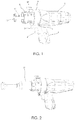
Figure 1 . Shows a perspective view of the device. -
Figure 2 . Shows a perspective view of the device with the container of the sealing material incorporated. -
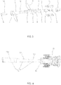
Figure 3 . Shows a linearly exploded view of the mechanical components. -
Figure 4 . Shows a perspective view of the gear module with the extendable shaft. - According to the disclosed illustrations and always respecting the numbering present therein, a preferred, but not limiting, embodiment of the invention is explained below wherein the mixing device and applicator for sealants comprises a handle (1) which houses a trigger (2), a rotation speed regulator (3) and a rotation sense selector (4).
- A modular casing or enclosure (5) rests on said handle (1) which is closed in the rear portion by means of one of said modules and in the front portion by means of a closing bushing (6) fastened thereto preferably by means of screws.
- In the front portion of the device a sheath (7) is arranged with a tightening head (8) which is coupled to the device preferably by means of an anchoring system made up of a series of protuberances (9) present therein and introduced through secured tracks (10) existing in the front portion of the device.
- The modular casing or enclosure (5) houses on the inside thereof the mechanisms, transmissions and gears described below;
- A rotor (23).
- A gear module (11) with a clutch coupled to a rotor (23) powered by an electrical current or by means of a pneumatic system.
- An extendable shaft (12), projected from the gear module (11) and resting on an axial bearing (22), which is made up of a first fixed section (12.1), a second movable section (12.2), a third also movable section (12.3) both with longitudinal movement and a plunger element (13) of the pistons present in the containers (21) of sealant material.
- A cylinder (14), projects from the closing bushing (6), coupled to said gear module (11) and which rests on a radial bearing (18) arranged thereon. The arrangement of the mentioned bearing on the cylinder is made between a contoured projection (15) present in the middle portion thereof and the closing bushing (6) present therein. The mentioned cylinder (14) has tracks (10) with housing in the front portion thereof.
- A telescopic guiding system of the extendable shaft is located inside the cylinder (14) and is made up of an adapter (17) with a geometric transition from circular to hexagonal shapes in a preferred embodiment located between the gear module (11) and a telescopic guide made up of two movable sections (16.1 and 16.2) with an identical hexagonal geometric shape and different sizes which is dragged by the extendable shaft (12) itself. The circular portion of the adapter (17) is extended in a linear sense at a distance long enough for the container of the sealant material to fit proportionally.
- Said closing bushing (6) incorporates a system for locking or releasing the rotation of the cylinder preferably made up of a retention rod (19) with a lever head and guiding and closing means (20) thereof.
Claims (13)
- A mixing device and applicator for sealants having a main body and a handle (1), characterised in that the main body comprises:- A removable sheath (7) for carrying containers of sealant material- A rotating cylinder (14) whereon the sheath (7) is coupled- A gear module (11) for varying rotation- An extendable shaft (12) with a telescopic guiding system- A plunger element for sealant material (13)- A rotor (23)- A modular enclosing casing (5).
- The mixing device and applicator for sealants according to claim 1, characterised in that the sheath (7) has a head (8) for fixing the container (21) and for helping in the coupling thereof to the device.
- The mixing device and applicator for sealants according to claims 1 and 2, characterised in that the sheath (7) is coupled to the device in the rotating cylinder (14) preferably by means of the guiding and subsequent seating of a series of protuberances (9) present in the sheath (7) along rails (10) present in the cylinder (14).
- The mixing device and applicator for sealants according to claims 1 and 3, characterised in that the device comprises a locking or release system (19 and 20) for the rotation of the cylinder (14).
- The mixing device and applicator for sealants according to claim 1, characterised in that the modular casing (5) has a closing bushing (6) in the front portion thereof.
- The mixing device and applicator for sealants according to claims 1, 2, 3, 4 and 5, characterised in that the rotating cylinder (14) projects from the closing bushing (6).
- The mixing device and applicator for sealants according to claims 1, 2, 3, 4, 5, and 6, characterised in that the front portion of the cylinder (14) rests on the closing bushing (6) through a radial bearing (18) placed on the cylinder and braked by a contoured projection (15) present in the middle portion of said cylinder.
- The mixing device and applicator for sealants according to claim 1, characterised in that an extendable shaft (12) projects from the gear module (11).
- The mixing device and applicator for sealants according to claims 1 and 8, characterised in that the same extendable shaft (12) drags a telescopic guide made up of two movable sections (16.1 and 16.2) with edges.
- The mixing device and applicator for sealants according to claims 1, 2, 3, 4, 5, 6, 7, 8, and 9, characterised in that between the gear module (11) and the telescopic guide (16.1 and 16.2) it has an adapter (17) with a transition from circular to edged geometric shapes.
- The mixing device and applicator for sealants according to claim 10, characterised in that the circular portion of the adapter (17) is extended in a linear sense at a distance long enough for the container of the sealant material to fit proportionally.
- The mixing device and applicator for sealants according to claim 1, characterised in that the gear module (11) is coupled to a rotor (23) powered by an electrical current or by means of a pneumatic system.
- The mixing device and applicator for sealants according to claim 1, characterised in that the handle houses an actuator of the rotor (2), a rotation speed selector (3) and a selector (4) of the sense thereof.
Applications Claiming Priority (2)
| Application Number | Priority Date | Filing Date | Title |
|---|---|---|---|
| ES201600784A ES2664581B1 (en) | 2016-09-20 | 2016-09-20 | Sealant mixer and applicator device |
| PCT/ES2017/070598 WO2018055221A1 (en) | 2016-09-20 | 2017-09-06 | Mixing device and applicator for sealants |
Publications (3)
| Publication Number | Publication Date |
|---|---|
| EP3517221A1 true EP3517221A1 (en) | 2019-07-31 |
| EP3517221A4 EP3517221A4 (en) | 2020-06-17 |
| EP3517221B1 EP3517221B1 (en) | 2022-02-09 |
Family
ID=61690801
Family Applications (1)
| Application Number | Title | Priority Date | Filing Date |
|---|---|---|---|
| EP17852467.4A Not-in-force EP3517221B1 (en) | 2016-09-20 | 2017-09-06 | Mixing device and applicator for sealants |
Country Status (4)
| Country | Link |
|---|---|
| US (1) | US20200030843A1 (en) |
| EP (1) | EP3517221B1 (en) |
| ES (1) | ES2664581B1 (en) |
| WO (1) | WO2018055221A1 (en) |
Families Citing this family (1)
| Publication number | Priority date | Publication date | Assignee | Title |
|---|---|---|---|---|
| WO2023091134A1 (en) * | 2021-11-17 | 2023-05-25 | Cft Llc | Applicator |
Family Cites Families (11)
| Publication number | Priority date | Publication date | Assignee | Title |
|---|---|---|---|---|
| JPS59222250A (en) * | 1983-05-31 | 1984-12-13 | Matsushita Electric Works Ltd | Extruder for viscous material |
| JPS61238358A (en) * | 1985-04-13 | 1986-10-23 | Matsushita Electric Works Ltd | Viscous agent extruder |
| IT1266695B1 (en) * | 1994-02-16 | 1997-01-14 | Stefania Ceron | GUN EXTRUDER |
| DE29819661U1 (en) * | 1998-11-04 | 1999-02-25 | Kress-Elektrik GmbH & Co Elektromotorenfabrik, 72406 Bisingen | Device for squeezing and dispensing flowable multi-components |
| US6926177B1 (en) * | 2000-03-31 | 2005-08-09 | William M. Scott | Device for dispensing substance from a cartridge |
| DE102005009247A1 (en) * | 2005-02-25 | 2006-08-31 | Bruno Castellucci | Electric hand tool, for the application of a jointing material, has a leading housing section with a jet and cartridge holder and a trailing section enclosing the drive for a plunger and the operating system |
| CN101557996A (en) * | 2006-12-15 | 2009-10-14 | 3M创新有限公司 | Mixing and dispensing curable multi-component materials |
| AU2010242894A1 (en) * | 2009-04-30 | 2011-11-17 | Hyperbranch Medical Technology, Inc. | Self-contained medical applicators for surgical sealants, and methods of use thereof |
| EP2606986A1 (en) * | 2011-12-21 | 2013-06-26 | Sika Technology AG | Driving equipment for dosing and mixing apparatus |
| DE102014106873B4 (en) * | 2014-05-15 | 2016-12-08 | Heraeus Medical Gmbh | Apparatus and method for mixing a multi-component cement |
| DE102015101126A1 (en) * | 2015-01-27 | 2016-07-28 | Heraeus Medical Gmbh | Paste application device for mixing a paste of two components |
-
2016
- 2016-09-20 ES ES201600784A patent/ES2664581B1/en not_active Expired - Fee Related
-
2017
- 2017-09-06 WO PCT/ES2017/070598 patent/WO2018055221A1/en not_active Ceased
- 2017-09-06 US US16/332,423 patent/US20200030843A1/en not_active Abandoned
- 2017-09-06 EP EP17852467.4A patent/EP3517221B1/en not_active Not-in-force
Also Published As
| Publication number | Publication date |
|---|---|
| WO2018055221A1 (en) | 2018-03-29 |
| EP3517221A4 (en) | 2020-06-17 |
| ES2664581A1 (en) | 2018-04-20 |
| EP3517221B1 (en) | 2022-02-09 |
| US20200030843A1 (en) | 2020-01-30 |
| ES2664581B1 (en) | 2019-01-30 |
Similar Documents
| Publication | Publication Date | Title |
|---|---|---|
| CN102089084B (en) | Dispensing assembly comprising a cartridge with bag | |
| US7420341B2 (en) | Power tool and motor controller | |
| EP2564942B1 (en) | Powered dispensing tool | |
| US10864540B2 (en) | Material dispenser control assembly | |
| RU2614685C2 (en) | Drive device of dosing mixing machine | |
| US9278437B2 (en) | Handheld power tool, in particular a power drill or screwdriver | |
| CN203578058U (en) | power distribution tool | |
| CN204366915U (en) | Additional grip and possessed the power tool of additional grip | |
| US4024994A (en) | Power operated caulking gun | |
| CA3038348C (en) | Device for applying a transferable substance | |
| KR101132130B1 (en) | Linear electric actuator | |
| CN104010737A (en) | Driving Device for Metering and Mixing Apparatus for Multi-component Substances | |
| US20120116301A1 (en) | Supply unit for a mixer of two-phase compounds | |
| EP3517221B1 (en) | Mixing device and applicator for sealants | |
| JP2007090345A (en) | Pneumatic discharge system and method utilizing linear actuation | |
| US20120285299A1 (en) | Screwdriver having a removable rod member | |
| EP1882525A2 (en) | Caulking gun | |
| US11478332B2 (en) | Dental material delivery system | |
| US20160016195A1 (en) | Multicomponent dispenser | |
| EP2033734A1 (en) | Safety device for a peck drill | |
| JP2013198658A (en) | Medicine injector and medicine mixing device | |
| TWI448361B (en) | Screw driver | |
| EP3167956A1 (en) | Dispenser and mixer for disposable cartridges | |
| JP2012081418A (en) | Mixing and discharging device | |
| JP4959202B2 (en) | Grip for absorbing the reaction force of rotary drive tools |
Legal Events
| Date | Code | Title | Description |
|---|---|---|---|
| STAA | Information on the status of an ep patent application or granted ep patent |
Free format text: STATUS: THE INTERNATIONAL PUBLICATION HAS BEEN MADE |
|
| PUAI | Public reference made under article 153(3) epc to a published international application that has entered the european phase |
Free format text: ORIGINAL CODE: 0009012 |
|
| STAA | Information on the status of an ep patent application or granted ep patent |
Free format text: STATUS: REQUEST FOR EXAMINATION WAS MADE |
|
| 17P | Request for examination filed |
Effective date: 20190415 |
|
| AK | Designated contracting states |
Kind code of ref document: A1 Designated state(s): AL AT BE BG CH CY CZ DE DK EE ES FI FR GB GR HR HU IE IS IT LI LT LU LV MC MK MT NL NO PL PT RO RS SE SI SK SM TR |
|
| AX | Request for extension of the european patent |
Extension state: BA ME |
|
| DAV | Request for validation of the european patent (deleted) | ||
| DAX | Request for extension of the european patent (deleted) | ||
| A4 | Supplementary search report drawn up and despatched |
Effective date: 20200520 |
|
| RIC1 | Information provided on ipc code assigned before grant |
Ipc: B01F 15/02 20060101ALI20200514BHEP Ipc: B05C 17/005 20060101AFI20200514BHEP Ipc: B05C 17/01 20060101ALI20200514BHEP Ipc: B01F 9/02 20060101ALI20200514BHEP |
|
| PUAJ | Public notification under rule 129 epc |
Free format text: ORIGINAL CODE: 0009425 |
|
| 32PN | Public notification |
Free format text: INVITATION TO GIVE NOTICE OF APPOINTMENT OF A PROFESSIONAL REPRESENTATIVE (EPO FORM 2572 DATED 07/12/20 AND 15/01/21) |
|
| GRAP | Despatch of communication of intention to grant a patent |
Free format text: ORIGINAL CODE: EPIDOSNIGR1 |
|
| STAA | Information on the status of an ep patent application or granted ep patent |
Free format text: STATUS: GRANT OF PATENT IS INTENDED |
|
| INTG | Intention to grant announced |
Effective date: 20210930 |
|
| GRAS | Grant fee paid |
Free format text: ORIGINAL CODE: EPIDOSNIGR3 |
|
| GRAA | (expected) grant |
Free format text: ORIGINAL CODE: 0009210 |
|
| STAA | Information on the status of an ep patent application or granted ep patent |
Free format text: STATUS: THE PATENT HAS BEEN GRANTED |
|
| AK | Designated contracting states |
Kind code of ref document: B1 Designated state(s): AL AT BE BG CH CY CZ DE DK EE ES FI FR GB GR HR HU IE IS IT LI LT LU LV MC MK MT NL NO PL PT RO RS SE SI SK SM TR |
|
| REG | Reference to a national code |
Ref country code: GB Ref legal event code: FG4D |
|
| REG | Reference to a national code |
Ref country code: CH Ref legal event code: EP Ref country code: AT Ref legal event code: REF Ref document number: 1467179 Country of ref document: AT Kind code of ref document: T Effective date: 20220215 |
|
| REG | Reference to a national code |
Ref country code: IE Ref legal event code: FG4D |
|
| REG | Reference to a national code |
Ref country code: DE Ref legal event code: R096 Ref document number: 602017053264 Country of ref document: DE |
|
| REG | Reference to a national code |
Ref country code: LT Ref legal event code: MG9D |
|
| REG | Reference to a national code |
Ref country code: NL Ref legal event code: MP Effective date: 20220209 |
|
| REG | Reference to a national code |
Ref country code: AT Ref legal event code: MK05 Ref document number: 1467179 Country of ref document: AT Kind code of ref document: T Effective date: 20220209 |
|
| PG25 | Lapsed in a contracting state [announced via postgrant information from national office to epo] |
Ref country code: SE Free format text: LAPSE BECAUSE OF FAILURE TO SUBMIT A TRANSLATION OF THE DESCRIPTION OR TO PAY THE FEE WITHIN THE PRESCRIBED TIME-LIMIT Effective date: 20220209 Ref country code: RS Free format text: LAPSE BECAUSE OF FAILURE TO SUBMIT A TRANSLATION OF THE DESCRIPTION OR TO PAY THE FEE WITHIN THE PRESCRIBED TIME-LIMIT Effective date: 20220209 Ref country code: PT Free format text: LAPSE BECAUSE OF FAILURE TO SUBMIT A TRANSLATION OF THE DESCRIPTION OR TO PAY THE FEE WITHIN THE PRESCRIBED TIME-LIMIT Effective date: 20220609 Ref country code: NO Free format text: LAPSE BECAUSE OF FAILURE TO SUBMIT A TRANSLATION OF THE DESCRIPTION OR TO PAY THE FEE WITHIN THE PRESCRIBED TIME-LIMIT Effective date: 20220509 Ref country code: NL Free format text: LAPSE BECAUSE OF FAILURE TO SUBMIT A TRANSLATION OF THE DESCRIPTION OR TO PAY THE FEE WITHIN THE PRESCRIBED TIME-LIMIT Effective date: 20220209 Ref country code: LT Free format text: LAPSE BECAUSE OF FAILURE TO SUBMIT A TRANSLATION OF THE DESCRIPTION OR TO PAY THE FEE WITHIN THE PRESCRIBED TIME-LIMIT Effective date: 20220209 Ref country code: HR Free format text: LAPSE BECAUSE OF FAILURE TO SUBMIT A TRANSLATION OF THE DESCRIPTION OR TO PAY THE FEE WITHIN THE PRESCRIBED TIME-LIMIT Effective date: 20220209 Ref country code: ES Free format text: LAPSE BECAUSE OF FAILURE TO SUBMIT A TRANSLATION OF THE DESCRIPTION OR TO PAY THE FEE WITHIN THE PRESCRIBED TIME-LIMIT Effective date: 20220209 Ref country code: BG Free format text: LAPSE BECAUSE OF FAILURE TO SUBMIT A TRANSLATION OF THE DESCRIPTION OR TO PAY THE FEE WITHIN THE PRESCRIBED TIME-LIMIT Effective date: 20220509 |
|
| PG25 | Lapsed in a contracting state [announced via postgrant information from national office to epo] |
Ref country code: PL Free format text: LAPSE BECAUSE OF FAILURE TO SUBMIT A TRANSLATION OF THE DESCRIPTION OR TO PAY THE FEE WITHIN THE PRESCRIBED TIME-LIMIT Effective date: 20220209 Ref country code: LV Free format text: LAPSE BECAUSE OF FAILURE TO SUBMIT A TRANSLATION OF THE DESCRIPTION OR TO PAY THE FEE WITHIN THE PRESCRIBED TIME-LIMIT Effective date: 20220209 Ref country code: GR Free format text: LAPSE BECAUSE OF FAILURE TO SUBMIT A TRANSLATION OF THE DESCRIPTION OR TO PAY THE FEE WITHIN THE PRESCRIBED TIME-LIMIT Effective date: 20220510 Ref country code: FI Free format text: LAPSE BECAUSE OF FAILURE TO SUBMIT A TRANSLATION OF THE DESCRIPTION OR TO PAY THE FEE WITHIN THE PRESCRIBED TIME-LIMIT Effective date: 20220209 Ref country code: AT Free format text: LAPSE BECAUSE OF FAILURE TO SUBMIT A TRANSLATION OF THE DESCRIPTION OR TO PAY THE FEE WITHIN THE PRESCRIBED TIME-LIMIT Effective date: 20220209 |
|
| PG25 | Lapsed in a contracting state [announced via postgrant information from national office to epo] |
Ref country code: IS Free format text: LAPSE BECAUSE OF FAILURE TO SUBMIT A TRANSLATION OF THE DESCRIPTION OR TO PAY THE FEE WITHIN THE PRESCRIBED TIME-LIMIT Effective date: 20220609 |
|
| PG25 | Lapsed in a contracting state [announced via postgrant information from national office to epo] |
Ref country code: SM Free format text: LAPSE BECAUSE OF FAILURE TO SUBMIT A TRANSLATION OF THE DESCRIPTION OR TO PAY THE FEE WITHIN THE PRESCRIBED TIME-LIMIT Effective date: 20220209 Ref country code: SK Free format text: LAPSE BECAUSE OF FAILURE TO SUBMIT A TRANSLATION OF THE DESCRIPTION OR TO PAY THE FEE WITHIN THE PRESCRIBED TIME-LIMIT Effective date: 20220209 Ref country code: RO Free format text: LAPSE BECAUSE OF FAILURE TO SUBMIT A TRANSLATION OF THE DESCRIPTION OR TO PAY THE FEE WITHIN THE PRESCRIBED TIME-LIMIT Effective date: 20220209 Ref country code: EE Free format text: LAPSE BECAUSE OF FAILURE TO SUBMIT A TRANSLATION OF THE DESCRIPTION OR TO PAY THE FEE WITHIN THE PRESCRIBED TIME-LIMIT Effective date: 20220209 Ref country code: DK Free format text: LAPSE BECAUSE OF FAILURE TO SUBMIT A TRANSLATION OF THE DESCRIPTION OR TO PAY THE FEE WITHIN THE PRESCRIBED TIME-LIMIT Effective date: 20220209 Ref country code: CZ Free format text: LAPSE BECAUSE OF FAILURE TO SUBMIT A TRANSLATION OF THE DESCRIPTION OR TO PAY THE FEE WITHIN THE PRESCRIBED TIME-LIMIT Effective date: 20220209 |
|
| REG | Reference to a national code |
Ref country code: DE Ref legal event code: R097 Ref document number: 602017053264 Country of ref document: DE |
|
| PG25 | Lapsed in a contracting state [announced via postgrant information from national office to epo] |
Ref country code: AL Free format text: LAPSE BECAUSE OF FAILURE TO SUBMIT A TRANSLATION OF THE DESCRIPTION OR TO PAY THE FEE WITHIN THE PRESCRIBED TIME-LIMIT Effective date: 20220209 |
|
| PLBE | No opposition filed within time limit |
Free format text: ORIGINAL CODE: 0009261 |
|
| STAA | Information on the status of an ep patent application or granted ep patent |
Free format text: STATUS: NO OPPOSITION FILED WITHIN TIME LIMIT |
|
| 26N | No opposition filed |
Effective date: 20221110 |
|
| PG25 | Lapsed in a contracting state [announced via postgrant information from national office to epo] |
Ref country code: SI Free format text: LAPSE BECAUSE OF FAILURE TO SUBMIT A TRANSLATION OF THE DESCRIPTION OR TO PAY THE FEE WITHIN THE PRESCRIBED TIME-LIMIT Effective date: 20220209 |
|
| REG | Reference to a national code |
Ref country code: DE Ref legal event code: R119 Ref document number: 602017053264 Country of ref document: DE |
|
| PG25 | Lapsed in a contracting state [announced via postgrant information from national office to epo] |
Ref country code: MC Free format text: LAPSE BECAUSE OF FAILURE TO SUBMIT A TRANSLATION OF THE DESCRIPTION OR TO PAY THE FEE WITHIN THE PRESCRIBED TIME-LIMIT Effective date: 20220209 |
|
| REG | Reference to a national code |
Ref country code: CH Ref legal event code: PL |
|
| GBPC | Gb: european patent ceased through non-payment of renewal fee |
Effective date: 20220906 |
|
| REG | Reference to a national code |
Ref country code: BE Ref legal event code: MM Effective date: 20220930 |
|
| PG25 | Lapsed in a contracting state [announced via postgrant information from national office to epo] |
Ref country code: LU Free format text: LAPSE BECAUSE OF NON-PAYMENT OF DUE FEES Effective date: 20220906 |
|
| PG25 | Lapsed in a contracting state [announced via postgrant information from national office to epo] |
Ref country code: LI Free format text: LAPSE BECAUSE OF NON-PAYMENT OF DUE FEES Effective date: 20220930 Ref country code: IT Free format text: LAPSE BECAUSE OF FAILURE TO SUBMIT A TRANSLATION OF THE DESCRIPTION OR TO PAY THE FEE WITHIN THE PRESCRIBED TIME-LIMIT Effective date: 20220209 Ref country code: IE Free format text: LAPSE BECAUSE OF NON-PAYMENT OF DUE FEES Effective date: 20220906 Ref country code: FR Free format text: LAPSE BECAUSE OF NON-PAYMENT OF DUE FEES Effective date: 20220930 Ref country code: DE Free format text: LAPSE BECAUSE OF NON-PAYMENT OF DUE FEES Effective date: 20230401 Ref country code: CH Free format text: LAPSE BECAUSE OF NON-PAYMENT OF DUE FEES Effective date: 20220930 |
|
| PG25 | Lapsed in a contracting state [announced via postgrant information from national office to epo] |
Ref country code: BE Free format text: LAPSE BECAUSE OF NON-PAYMENT OF DUE FEES Effective date: 20220930 |
|
| PG25 | Lapsed in a contracting state [announced via postgrant information from national office to epo] |
Ref country code: GB Free format text: LAPSE BECAUSE OF NON-PAYMENT OF DUE FEES Effective date: 20220906 |
|
| PG25 | Lapsed in a contracting state [announced via postgrant information from national office to epo] |
Ref country code: HU Free format text: LAPSE BECAUSE OF FAILURE TO SUBMIT A TRANSLATION OF THE DESCRIPTION OR TO PAY THE FEE WITHIN THE PRESCRIBED TIME-LIMIT; INVALID AB INITIO Effective date: 20170906 |
|
| PG25 | Lapsed in a contracting state [announced via postgrant information from national office to epo] |
Ref country code: CY Free format text: LAPSE BECAUSE OF FAILURE TO SUBMIT A TRANSLATION OF THE DESCRIPTION OR TO PAY THE FEE WITHIN THE PRESCRIBED TIME-LIMIT Effective date: 20220209 |
|
| PG25 | Lapsed in a contracting state [announced via postgrant information from national office to epo] |
Ref country code: MK Free format text: LAPSE BECAUSE OF FAILURE TO SUBMIT A TRANSLATION OF THE DESCRIPTION OR TO PAY THE FEE WITHIN THE PRESCRIBED TIME-LIMIT Effective date: 20220209 |
|
| PG25 | Lapsed in a contracting state [announced via postgrant information from national office to epo] |
Ref country code: TR Free format text: LAPSE BECAUSE OF FAILURE TO SUBMIT A TRANSLATION OF THE DESCRIPTION OR TO PAY THE FEE WITHIN THE PRESCRIBED TIME-LIMIT Effective date: 20220209 |
|
| PG25 | Lapsed in a contracting state [announced via postgrant information from national office to epo] |
Ref country code: MT Free format text: LAPSE BECAUSE OF FAILURE TO SUBMIT A TRANSLATION OF THE DESCRIPTION OR TO PAY THE FEE WITHIN THE PRESCRIBED TIME-LIMIT Effective date: 20220209 |