EP3517170A1 - Method of processing fluoroscopy images - Google Patents
Method of processing fluoroscopy images Download PDFInfo
- Publication number
- EP3517170A1 EP3517170A1 EP18185243.5A EP18185243A EP3517170A1 EP 3517170 A1 EP3517170 A1 EP 3517170A1 EP 18185243 A EP18185243 A EP 18185243A EP 3517170 A1 EP3517170 A1 EP 3517170A1
- Authority
- EP
- European Patent Office
- Prior art keywords
- motion
- annotations
- image
- sequence
- late
- Prior art date
- Legal status (The legal status is an assumption and is not a legal conclusion. Google has not performed a legal analysis and makes no representation as to the accuracy of the status listed.)
- Granted
Links
Images




Classifications
-
- A—HUMAN NECESSITIES
- A61—MEDICAL OR VETERINARY SCIENCE; HYGIENE
- A61B—DIAGNOSIS; SURGERY; IDENTIFICATION
- A61B6/00—Apparatus or devices for radiation diagnosis; Apparatus or devices for radiation diagnosis combined with radiation therapy equipment
- A61B6/48—Diagnostic techniques
- A61B6/486—Diagnostic techniques involving generating temporal series of image data
- A61B6/487—Diagnostic techniques involving generating temporal series of image data involving fluoroscopy
-
- G—PHYSICS
- G06—COMPUTING OR CALCULATING; COUNTING
- G06T—IMAGE DATA PROCESSING OR GENERATION, IN GENERAL
- G06T7/00—Image analysis
- G06T7/0002—Inspection of images, e.g. flaw detection
- G06T7/0012—Biomedical image inspection
-
- A—HUMAN NECESSITIES
- A61—MEDICAL OR VETERINARY SCIENCE; HYGIENE
- A61B—DIAGNOSIS; SURGERY; IDENTIFICATION
- A61B6/00—Apparatus or devices for radiation diagnosis; Apparatus or devices for radiation diagnosis combined with radiation therapy equipment
- A61B6/12—Arrangements for detecting or locating foreign bodies
-
- A—HUMAN NECESSITIES
- A61—MEDICAL OR VETERINARY SCIENCE; HYGIENE
- A61B—DIAGNOSIS; SURGERY; IDENTIFICATION
- A61B6/00—Apparatus or devices for radiation diagnosis; Apparatus or devices for radiation diagnosis combined with radiation therapy equipment
- A61B6/48—Diagnostic techniques
- A61B6/484—Diagnostic techniques involving phase contrast X-ray imaging
-
- A—HUMAN NECESSITIES
- A61—MEDICAL OR VETERINARY SCIENCE; HYGIENE
- A61B—DIAGNOSIS; SURGERY; IDENTIFICATION
- A61B6/00—Apparatus or devices for radiation diagnosis; Apparatus or devices for radiation diagnosis combined with radiation therapy equipment
- A61B6/48—Diagnostic techniques
- A61B6/485—Diagnostic techniques involving fluorescence X-ray imaging
-
- A—HUMAN NECESSITIES
- A61—MEDICAL OR VETERINARY SCIENCE; HYGIENE
- A61B—DIAGNOSIS; SURGERY; IDENTIFICATION
- A61B6/00—Apparatus or devices for radiation diagnosis; Apparatus or devices for radiation diagnosis combined with radiation therapy equipment
- A61B6/50—Apparatus or devices for radiation diagnosis; Apparatus or devices for radiation diagnosis combined with radiation therapy equipment specially adapted for specific body parts; specially adapted for specific clinical applications
- A61B6/504—Apparatus or devices for radiation diagnosis; Apparatus or devices for radiation diagnosis combined with radiation therapy equipment specially adapted for specific body parts; specially adapted for specific clinical applications for diagnosis of blood vessels, e.g. by angiography
-
- A—HUMAN NECESSITIES
- A61—MEDICAL OR VETERINARY SCIENCE; HYGIENE
- A61B—DIAGNOSIS; SURGERY; IDENTIFICATION
- A61B6/00—Apparatus or devices for radiation diagnosis; Apparatus or devices for radiation diagnosis combined with radiation therapy equipment
- A61B6/54—Control of apparatus or devices for radiation diagnosis
- A61B6/547—Control of apparatus or devices for radiation diagnosis involving tracking of position of the device or parts of the device
-
- G—PHYSICS
- G06—COMPUTING OR CALCULATING; COUNTING
- G06T—IMAGE DATA PROCESSING OR GENERATION, IN GENERAL
- G06T7/00—Image analysis
- G06T7/20—Analysis of motion
- G06T7/246—Analysis of motion using feature-based methods, e.g. the tracking of corners or segments
-
- A—HUMAN NECESSITIES
- A61—MEDICAL OR VETERINARY SCIENCE; HYGIENE
- A61B—DIAGNOSIS; SURGERY; IDENTIFICATION
- A61B90/00—Instruments, implements or accessories specially adapted for surgery or diagnosis and not covered by any of the groups A61B1/00 - A61B50/00, e.g. for luxation treatment or for protecting wound edges
- A61B90/36—Image-producing devices or illumination devices not otherwise provided for
- A61B90/37—Surgical systems with images on a monitor during operation
- A61B2090/376—Surgical systems with images on a monitor during operation using X-rays, e.g. fluoroscopy
-
- A—HUMAN NECESSITIES
- A61—MEDICAL OR VETERINARY SCIENCE; HYGIENE
- A61B—DIAGNOSIS; SURGERY; IDENTIFICATION
- A61B6/00—Apparatus or devices for radiation diagnosis; Apparatus or devices for radiation diagnosis combined with radiation therapy equipment
- A61B6/02—Arrangements for diagnosis sequentially in different planes; Stereoscopic radiation diagnosis
- A61B6/03—Computed tomography [CT]
- A61B6/032—Transmission computed tomography [CT]
-
- A—HUMAN NECESSITIES
- A61—MEDICAL OR VETERINARY SCIENCE; HYGIENE
- A61B—DIAGNOSIS; SURGERY; IDENTIFICATION
- A61B6/00—Apparatus or devices for radiation diagnosis; Apparatus or devices for radiation diagnosis combined with radiation therapy equipment
- A61B6/46—Arrangements for interfacing with the operator or the patient
- A61B6/461—Displaying means of special interest
- A61B6/463—Displaying means of special interest characterised by displaying multiple images or images and diagnostic data on one display
-
- A—HUMAN NECESSITIES
- A61—MEDICAL OR VETERINARY SCIENCE; HYGIENE
- A61B—DIAGNOSIS; SURGERY; IDENTIFICATION
- A61B6/00—Apparatus or devices for radiation diagnosis; Apparatus or devices for radiation diagnosis combined with radiation therapy equipment
- A61B6/48—Diagnostic techniques
- A61B6/481—Diagnostic techniques involving the use of contrast agents
-
- A—HUMAN NECESSITIES
- A61—MEDICAL OR VETERINARY SCIENCE; HYGIENE
- A61N—ELECTROTHERAPY; MAGNETOTHERAPY; RADIATION THERAPY; ULTRASOUND THERAPY
- A61N1/00—Electrotherapy; Circuits therefor
- A61N1/18—Applying electric currents by contact electrodes
- A61N1/32—Applying electric currents by contact electrodes alternating or intermittent currents
- A61N1/36—Applying electric currents by contact electrodes alternating or intermittent currents for stimulation
- A61N1/362—Heart stimulators
- A61N1/3627—Heart stimulators for treating a mechanical deficiency of the heart, e.g. congestive heart failure or cardiomyopathy
-
- G—PHYSICS
- G06—COMPUTING OR CALCULATING; COUNTING
- G06T—IMAGE DATA PROCESSING OR GENERATION, IN GENERAL
- G06T2207/00—Indexing scheme for image analysis or image enhancement
- G06T2207/10—Image acquisition modality
- G06T2207/10016—Video; Image sequence
-
- G—PHYSICS
- G06—COMPUTING OR CALCULATING; COUNTING
- G06T—IMAGE DATA PROCESSING OR GENERATION, IN GENERAL
- G06T2207/00—Indexing scheme for image analysis or image enhancement
- G06T2207/10—Image acquisition modality
- G06T2207/10116—X-ray image
- G06T2207/10121—Fluoroscopy
-
- G—PHYSICS
- G06—COMPUTING OR CALCULATING; COUNTING
- G06T—IMAGE DATA PROCESSING OR GENERATION, IN GENERAL
- G06T2207/00—Indexing scheme for image analysis or image enhancement
- G06T2207/30—Subject of image; Context of image processing
- G06T2207/30004—Biomedical image processing
- G06T2207/30048—Heart; Cardiac
-
- G—PHYSICS
- G06—COMPUTING OR CALCULATING; COUNTING
- G06V—IMAGE OR VIDEO RECOGNITION OR UNDERSTANDING
- G06V2201/00—Indexing scheme relating to image or video recognition or understanding
- G06V2201/03—Recognition of patterns in medical or anatomical images
- G06V2201/031—Recognition of patterns in medical or anatomical images of internal organs
Definitions
- the invention describes a method of extracting mechanical activation of the left ventricle from a sequence of contrasted X-ray fluoroscopy images.
- the invention further describes an image processing arrangement, and a computer program product.
- CVD Cardiovascular disease
- CRT Cardiac resynchronization therapy
- LV sub-optimal left ventricle
- the coordinated contraction and expansion of the chambers of the heart are controlled by electrical systole and mechanical systole of the cardiac electrical conduction system.
- electrical systole electrical pulses travel through bundle branches of the myocardium. These signals trigger a response in the myocardial cells, resulting in muscular contraction or mechanical systole, with a certain timing between atrial and ventricular contractions.
- This biomechanical contraction of the myocardium is referred to as "mechanical activation”.
- the myocardium may contract unevenly, e.g. the right ventricle may contract before the left ventricle because of left bundle branch block (LBBB).
- LBBB left bundle branch block
- Scar tissue from an earlier infarct may also negatively affect the mechanical systole timing. It has been shown in several studies that positioning the LV lead in the latest-activating region of the myocardium can increase the likelihood of a positive response for CRT implants. However, the currently available procedures and equipment for identifying the latest-activating region of the myocardium are expensive. Cardiac magnetic resonance (CMR) imaging can detect scar tissue and interventricular dyssynchrony, thereby improving the outcome of CRT. However, this technique is expensive and not available in many clinical settings. Ultrasound speckle-tracking 2D radial strain imaging can be used to detect dyssynchrony in addition to identifying the latest activating segment, but requires a skilled operator.
- CMR Cardiac magnetic resonance
- Computed tomography despite the radiation risks associated with patient exposure, can be utilized to calculate the latest mechanically activating segment for optimal lead position. These methods all require additional pre-operative imaging. For these reasons, it is not standard clinical practice to identify the latest-activating myocardial region in advance of a CRT procedure.
- the method of extracting mechanical activation of the left ventricle from a sequence of contrasted X-ray fluoroscopy images comprises the steps of:
- venograms which may be acquired during the CRT procedure may be used to derive mechanical activation and identify the latest activating region of the LV.
- Each patient's coronary anatomy may be segmented from the venograms. These segmentations were then skeletonized and the branches of the coronary sinus (CS) were identified and tracked.
- CS coronary sinus
- the present invention provides a method of extracting mechanical activation of the left ventricle from contrasted X-ray fluoroscopy, i.e. to deduce information about mechanical systole of the left ventricle using a sequence of contrasted X-ray fluoroscopy images.
- the method consists of segmentation of the coronary veins, annotating the branches of the veins, tracking the 2D positions of the annotated branches throughout the fluoroscopy sequence, computing the principle components of the motion of the labels, projecting the motion to the axis corresponding to the first principle component and analysing the resulting motion curves.
- the motion is associated with the motion of the cardiac wall.
- mechanical activation is a term used to refer to mechanical systole, i.e. the contraction of the myocardium (with the left ventricle) in response to electrical systole.
- the inventive method allows the mechanical activation to be identified or "extracted” from a sequence of contrasted X-ray fluoroscopy images.
- the X-ray opaque contrast agent serves to make the blood vessels of the coronary sinus appear clearly in the X-ray images.
- a contrasted X-ray fluoroscopy is generally performed prior to or during a CRT procedure to allow the operator to observe placement of the CRT leads, for example leads of a bi-ventricular pacemaker.
- the invention is based on the insight that the coronary sinus essentially lies on the epicardium, so that contraction/dilation of the underlying myocardium results in corresponding movement of the CS, resulting in slight displacements of the CS blood vessels in successive images of a contrasted X-ray fluoroscopy procedure.
- the inventors have realised that mechanical systole timing can be extracted from such a sequence of images by tracking the movements of CS nodes or branches throughout the image sequence and applying a technique of principle component analysis (PCA) to the tracked motion data.
- PCA principle component analysis
- the inventive method presents a novel way of estimating mechanical activation information by tracking the motion of CS vessels in venograms.
- the approach does not require additional pre-operative imaging and enables guided CRT lead placement using only intra-operative X-ray fluoroscopy imaging. It is significantly easier and more economical to perform X-ray fluoroscopy during the CRT intervention and to apply the inventive PCA-based motion analysis of the annotated venous branches of the CS, instead of tracking the cardiac wall during an expensive MRI procedure.
- the image processing arrangement for extracting left ventricle mechanical activation information from a sequence of cardiac contrasted X-ray fluoroscopy images comprises:
- the inventive image processing arrangement is useful for a CRT suite in a clinic environment.
- the extracted information relating to mechanical activation of the left ventricle can guide CRT interventions so that these can be performed without preoperative imaging such as MRI.
- the inventive image processing arrangement can therefore be deployed at any site that is equipped with a catheterization laboratory.
- the computer program product comprises a computer program that is directly loadable into a memory of a control unit of an embodiment of the inventive image processing arrangement and comprises program elements for performing steps of the inventive method when the computer program is executed by the control unit of the image processing arrangement.
- the invention describes a method to extract mechanical activation of the left ventricle from contrasted X-ray fluoroscopy, said method comprising the steps of: segmentation of the coronary veins; annotating branches of the veins; tracking 2D positions of the annotated branches throughout the fluoroscopy sequence; computing the principle components of the motion of the labels; projecting the motion to the axis corresponding to the first principle component; and analyzing the resulting motion curves.
- the sequence of fluoroscopy images comprises images obtained over at least one complete cardiac cycle.
- the sequence of fluoroscopy images is obtained at a frame rate of at least 7.5 frames per second and/or at a resolution of at least 130 ms.
- a patient is subject to a contrast-enhanced fluoroscopy.
- the coronary veins are segmented in the images, i.e. the network of veins is identified and highlighted in the images.
- the resulting segmentation mask is then skeletonized (again, using known image processing techniques) to clearly show the "skeleton" of the branches of the coronary sinus.
- the results of such image processing steps i.e. a segmentation mask, a skeletonization layer, etc., can be presented to a user in a transparent layer overlaid on the original image.
- annotations or labels may be placed in a similar transparent layer, for example a layer that is overlaid on a skeletonization, or a layer that is overlaid on a fluoroscopy image, etc.
- the annotation module is realised to automatically identify a branch of the coronary veins and to place an annotation accordingly.
- the venous anatomy can vary from patient to patient, so that some of the great vessels of the left ventricle may not be completely visible in the images. However, it is sufficient to be able to identify one point on each potential target vein to place an LV lead.
- the step of annotating a branch of the CS comprises placing a label on that branch in an image of the image sequence. A label can be placed at any position along a branch of the CS.
- a label is placed at a vein bifurcation or node, since a bifurcation can be tracked more easily throughout the image sequence.
- an image showing the set of labels and the CS can be displayed to a user for approval or adjustment of the proposed set of labels.
- the annotation module can be realised to permit manual placement of annotations. Of course, with suitable software, it would be possible to carry out the annotation in a completely automated manner.
- the labels are placed in all images of the image sequence. The motion of the labels is compared and a decision is made between the vessels.
- multiple CS branches are labelled accurately and numbered that each branch can be tracked throughout the frames of the cardiac cycle captured during the contrasted X-ray fluoroscopy procedure.
- at least two annotations or labels are placed and tracked in the image sequence, whereby one label is placed at a suitable node in the target vein into which the operator wishes to place an LV lead.
- any number of annotations is possible, for example five, seven labels, etc.
- PCA Principle component analysis
- the question of relevance to the operator is which myocardial region is last to activate, i.e. myocardial region is delayed the most.
- This question can be answered by applying PCA to analyse the tracked label positions as follows.
- the main principle component is associated with cardiac motion.
- the motion of the labelled branches - i.e. the pixel displacements of the labels - is projected onto the axis corresponding to the main principle component, i.e. the Y-axis, and the displacement of each label is tracked over time, i.e. in each of the sequence of images.
- the displacement of each label is tracked over time, i.e. in each of the sequence of images.
- each label (a point on the CS) is expected to move "outwards” during dilation of the myocardium, and to move "inwards” during contraction.
- the ventricles may contract with significant delay.
- the points of contraction can be located by assessing the timing of the minima of the motion curves for the annotated CS branches.
- the minima - which define the points of myocardial contraction - are identified and their relative delay is measured.
- the "latest" minimum i.e. the most delayed minimum) identifies the vessel to be targeted during CRT delivery.
- a strain measure could be computed by investigating the relative motion of branches.
- any relative movement between two branches can be observed and interpreted, for example to identify akinetic vessel segments, and any underlying akinetic myocardium.
- Fig 1 illustrates a workflow to compute mechanical activation from X-ray fluoroscopy images
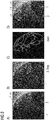
- Fig 2 shows image processing steps carried out on an exemplary venogram image obtained during the cardiac cycle.
- fluoroscopy images 2 or venograms are obtained during an angiography.
- Part of an exemplary image 2 of such a sequence is shown on the left in Fig 2 , and clearly indicates the network of vessels collectively referred to as the coronary sinus 1_CS.
- fluoroscopic sequences are acquired with the whole heart and its movement for at least one cardiac cycle so that a successful segmentation and annotation of the scan can be achieved.
- a fluoroscopic sequence 20 as shown in Fig 3 can be acquired at a suitable frame rate and temporal resolution, e.g. a frame rate of 7.5 frames per second at a temporal resolution of 133 ms; a frame rate of 15 frames per second at a temporal resolution of 67 ms, etc.
- a suitable frame rate and temporal resolution e.g. a frame rate of 7.5 frames per second at a temporal resolution of 133 ms; a frame rate of 15 frames per second at a temporal resolution of 67 ms, etc.
- the patient's coronary anatomy was segmented from the venograms in step 1.2.
- the coronary veins 1_CS are identified and extracted from the X-ray images, as indicated in part B of Fig 2 , which shows a segmentation layer 2seg overlaid on the image 2.
- These segmentations were then skeletonized in step 1.3 of Fig 1 .
- Segmentation and skeletonization are performed for multiple images in the sequence, and exemplary results are shown in part C of Fig 2 , which shows a skeletonization layer 2skel.
- the skeletonization layer 2skel is used to identify the locations of suitable labels L1, ..., L6 shown in part D of Fig 2 .
- the labels L1, ..., L6 are placed at suitable points along the branches of the blood vessels, for example at bifurcations of the coronary sinus 1_CS.
- the labels L1, ..., L6 are used in the subsequent tracking step given as step 1.4 in Fig 1 .
- Principle Component Analysis is used to track the movement of the labelled branches throughout the cardiac cycle, i.e. the movements of the branches are tracked throughout the image sequence.
- Fig. 3 shows a sequence 20 of venogram images 2 generated during a cardiac cycle, illustrating the tracking of bifurcations through the cardiac cycle. The lines connecting the images represent the movement of the labels over time. The foremost image 2 on the left indicates ten labels.
- Mechanical activation is derived from the tracked points by analysing their motion using PCA.
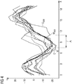
- Fig 4 shows an exemplary set of curves obtained by tracking the positions of ten labels over a complete cardiac cycle.
- the graph shows pixel displacement (Y-axis) against frame count (X-axis).
- curve C is identified as the primary motion curve, i.e. the motion curve corresponding to a label placed on a major vessel of the CS.
- the curve C late exhibits a distinct lag or delay ⁇ relative to the other curves, indicating that the corresponding branch of the CS is closest to the latest-activating myocardium region and would be the most suitable position for the LV lead that will be placed during the CRT procedure.
- An alternative method to compute mechanical activation from X-ray fluoroscopy is to measure the relative position of two labelled branches throughout the cardiac cycle.
- strain measurements can mistake normal or synchronous contraction of the myocardium as akinetic when two labels are close together.
- Temporal resolution cannot distinguish between the two different events.
- Fig 5 shows an exemplary image processing arrangement 3 for extracting left ventricle mechanical activation information from a sequence 20 of contrasted X-ray fluoroscopy images 2, which can be obtained during a guided or unguided CRT procedure, for example.
- the image processing arrangement 3 comprises a segmentation module 30 for performing segmentation of the coronary veins 1_CS in the images 2.
- the segmented CS can then be skeletonized in a suitable skeletonization unit 31.
- suitable bifurcations, branches or nodes of the CS can be automatically and/or manually identified as candidate points to track throughout the image sequence 20, and these points can be assigned labels or annotations by an annotation module 32.
- Manual input 320 is indicated, for example to approve and/or edit a set of annotations.
- a tracker module 33 identifies the position of each label in each image, and computes any deviation (in pixels) relative to the position of that label in the preceding image. This information is passed to a principle component analysis unit 33 that computes the principle components of the motion of the annotations. The results of the PCA are plotted as motion curves for each label, and the motion curves are presented to a user, for example on a display 35. The user or operator can then identify the most suitable region of the CS into which to place the LV lead in the CRT procedure.
- Fig 6 illustrates the underlying principle of the inventive method.
- a part of the annotated CS is shown relative to X and Y axes of an image plane.
- the diagram shows six labels L1, ..., L6 placed at suitable points, for example at points identified with the help of a skeletonized layer following a segmentation step.
- L3/L6 and label L3/L4 are labels that are placed into one or both of these branches of the CS.
- Each label L1, ..., L6 is essentially a point or pixel in the image, and can be defined by a coordinate pair as indicated by the X-coordinates x1, ..., x4 and Y-coordinates y1, ..., y6.
- the movement of the myocardial regions can be deduced by tracking the coordinates of the labels, i.e. by measuring any pixel offsets from one image to the next.
- the myocardium is undergoing expansion from the upper diagram to the lower diagram, and the coordinates of each label L1, ..., L6 alter accordingly.
- the X-offsets and Y-offsets of the labels in the images of the image sequence can be counted in pixels or any other appropriate unit, and fed to the PCA module which performs principle component analysis to estimate motion curves for each label.
Landscapes
- Engineering & Computer Science (AREA)
- Health & Medical Sciences (AREA)
- Life Sciences & Earth Sciences (AREA)
- Medical Informatics (AREA)
- Physics & Mathematics (AREA)
- Radiology & Medical Imaging (AREA)
- General Health & Medical Sciences (AREA)
- Nuclear Medicine, Radiotherapy & Molecular Imaging (AREA)
- Surgery (AREA)
- Public Health (AREA)
- Optics & Photonics (AREA)
- Biomedical Technology (AREA)
- Heart & Thoracic Surgery (AREA)
- Molecular Biology (AREA)
- High Energy & Nuclear Physics (AREA)
- Animal Behavior & Ethology (AREA)
- Biophysics (AREA)
- Pathology (AREA)
- Veterinary Medicine (AREA)
- Computer Vision & Pattern Recognition (AREA)
- General Physics & Mathematics (AREA)
- Theoretical Computer Science (AREA)
- Quality & Reliability (AREA)
- Multimedia (AREA)
- Vascular Medicine (AREA)
- Dentistry (AREA)
- Oral & Maxillofacial Surgery (AREA)
- Apparatus For Radiation Diagnosis (AREA)
Abstract
Description
- The invention describes a method of extracting mechanical activation of the left ventricle from a sequence of contrasted X-ray fluoroscopy images. The invention further describes an image processing arrangement, and a computer program product.
- Cardiovascular disease (CVD) is the leading global cause of death and accounts for over 30% of deaths per year. CVD contributes to 42% of deaths in the EU. CVD is associated with significant morbidity and mortality as first line treatments are not always effective in improving symptoms and quality of life.
- Congestive heart failure with dyssynchrony results in reduced function of the left ventricle as electrical impulses are delayed in transmission to the ventricles. In some patients, first-line pharmacological interventions are not always effective in improving symptoms and quality of life. Cardiac resynchronization therapy (CRT) has been shown to reduce mortality in patients with advanced drug-refractory heart failure, systolic dysfunction, chronic systolic heart failure and ventricular dyssynchrony. This minimally invasive intervention can alleviate symptoms, increase ejection fraction and shorten the electrocardiogram QRS duration. In spite of its advantages, CRT has a high non-response rate associated with sub-optimal left ventricle (LV) lead placement. This is because the presence of myocardium scar tissue in the position of the lead hinders the activation of the myocardium. Knowing where to place the LV lead is very challenging for operators performing the procedure as very little information is available to them during the procedure.
- The coordinated contraction and expansion of the chambers of the heart are controlled by electrical systole and mechanical systole of the cardiac electrical conduction system. During electrical systole, electrical pulses travel through bundle branches of the myocardium. These signals trigger a response in the myocardial cells, resulting in muscular contraction or mechanical systole, with a certain timing between atrial and ventricular contractions. This biomechanical contraction of the myocardium is referred to as "mechanical activation". In a patient with heart disease, the myocardium may contract unevenly, e.g. the right ventricle may contract before the left ventricle because of left bundle branch block (LBBB). Scar tissue from an earlier infarct may also negatively affect the mechanical systole timing. It has been shown in several studies that positioning the LV lead in the latest-activating region of the myocardium can increase the likelihood of a positive response for CRT implants. However, the currently available procedures and equipment for identifying the latest-activating region of the myocardium are expensive. Cardiac magnetic resonance (CMR) imaging can detect scar tissue and interventricular dyssynchrony, thereby improving the outcome of CRT. However, this technique is expensive and not available in many clinical settings. Ultrasound speckle-tracking 2D radial strain imaging can be used to detect dyssynchrony in addition to identifying the latest activating segment, but requires a skilled operator. Computed tomography (CT), despite the radiation risks associated with patient exposure, can be utilized to calculate the latest mechanically activating segment for optimal lead position. These methods all require additional pre-operative imaging. For these reasons, it is not standard clinical practice to identify the latest-activating myocardial region in advance of a CRT procedure.
- It is therefore an object of the invention to provide an improved method of identifying the latest-activating region of the myocardium.
- According to the invention, the method of extracting mechanical activation of the left ventricle from a sequence of contrasted X-ray fluoroscopy images comprises the steps of:
- processing the image sequence to perform segmentation of the coronary veins;
- annotating branches of the segmented coronary veins;
- tracking the positions of the annotations throughout the fluoroscopy image sequence;
- computing the principle components of the motion of the annotations from the tracked positions;
- projecting the motion of the annotations to the axis corresponding to a first principle component; and
- analyzing the resulting motion curves to identify a latest activating region of the left ventricle.
- In the method of the present invention, venograms which may be acquired during the CRT procedure may be used to derive mechanical activation and identify the latest activating region of the LV. Each patient's coronary anatomy may be segmented from the venograms. These segmentations were then skeletonized and the branches of the coronary sinus (CS) were identified and tracked.
- The present invention provides a method of extracting mechanical activation of the left ventricle from contrasted X-ray fluoroscopy, i.e. to deduce information about mechanical systole of the left ventricle using a sequence of contrasted X-ray fluoroscopy images. The method consists of segmentation of the coronary veins, annotating the branches of the veins, tracking the 2D positions of the annotated branches throughout the fluoroscopy sequence, computing the principle components of the motion of the labels, projecting the motion to the axis corresponding to the first principle component and analysing the resulting motion curves. The motion is associated with the motion of the cardiac wall.
- As explained above, mechanical activation is a term used to refer to mechanical systole, i.e. the contraction of the myocardium (with the left ventricle) in response to electrical systole. The inventive method allows the mechanical activation to be identified or "extracted" from a sequence of contrasted X-ray fluoroscopy images. In such a sequence of images, the X-ray opaque contrast agent serves to make the blood vessels of the coronary sinus appear clearly in the X-ray images. A contrasted X-ray fluoroscopy is generally performed prior to or during a CRT procedure to allow the operator to observe placement of the CRT leads, for example leads of a bi-ventricular pacemaker. The invention is based on the insight that the coronary sinus essentially lies on the epicardium, so that contraction/dilation of the underlying myocardium results in corresponding movement of the CS, resulting in slight displacements of the CS blood vessels in successive images of a contrasted X-ray fluoroscopy procedure. The inventors have realised that mechanical systole timing can be extracted from such a sequence of images by tracking the movements of CS nodes or branches throughout the image sequence and applying a technique of principle component analysis (PCA) to the tracked motion data. With the method of the present invention, no costly preoperative acquisition such as MRI or computed tomography is required, and there is no need for an ultrasound scan performed by a skilled operator. Furthermore, the success rate of unguided CRT interventions can be increased.
- The inventive method presents a novel way of estimating mechanical activation information by tracking the motion of CS vessels in venograms. The approach does not require additional pre-operative imaging and enables guided CRT lead placement using only intra-operative X-ray fluoroscopy imaging. It is significantly easier and more economical to perform X-ray fluoroscopy during the CRT intervention and to apply the inventive PCA-based motion analysis of the annotated venous branches of the CS, instead of tracking the cardiac wall during an expensive MRI procedure.
- According to the invention, the image processing arrangement for extracting left ventricle mechanical activation information from a sequence of cardiac contrasted X-ray fluoroscopy images comprises:
- a segmentation module realised to perform segmentation of the coronary veins;
- an annotation module for annotating branches of the segmented coronary veins;
- a tracker module adapted to track the positions of the annotations in the fluoroscopy image sequence; and
- a principle component analysis module for computing the principle components of the motion of the annotated branches and to present this information in the form of motion curves of the annotations.
- The inventive image processing arrangement is useful for a CRT suite in a clinic environment. The extracted information relating to mechanical activation of the left ventricle can guide CRT interventions so that these can be performed without preoperative imaging such as MRI. The inventive image processing arrangement can therefore be deployed at any site that is equipped with a catheterization laboratory.
- According to the invention, the computer program product comprises a computer program that is directly loadable into a memory of a control unit of an embodiment of the inventive image processing arrangement and comprises program elements for performing steps of the inventive method when the computer program is executed by the control unit of the image processing arrangement.
- The invention describes a method to extract mechanical activation of the left ventricle from contrasted X-ray fluoroscopy, said method comprising the steps of: segmentation of the coronary veins; annotating branches of the veins; tracking 2D positions of the annotated branches throughout the fluoroscopy sequence; computing the principle components of the motion of the labels; projecting the motion to the axis corresponding to the first principle component; and analyzing the resulting motion curves.
- Particularly advantageous embodiments and features of the invention are given by the dependent claims, as revealed in the following description. Features of different claim categories may be combined as appropriate to give further embodiments not described herein.
- In the following, without restricting the invention in any way, it may be assumed that the sequence of fluoroscopy images comprises images obtained over at least one complete cardiac cycle. Preferably, the sequence of fluoroscopy images is obtained at a frame rate of at least 7.5 frames per second and/or at a resolution of at least 130 ms.
- As indicated above, to compute the mechanical activation curves from X-ray images, a patient is subject to a contrast-enhanced fluoroscopy. Using known image processing techniques, the coronary veins are segmented in the images, i.e. the network of veins is identified and highlighted in the images. The resulting segmentation mask is then skeletonized (again, using known image processing techniques) to clearly show the "skeleton" of the branches of the coronary sinus. The results of such image processing steps, i.e. a segmentation mask, a skeletonization layer, etc., can be presented to a user in a transparent layer overlaid on the original image. Any annotations or labels may be placed in a similar transparent layer, for example a layer that is overlaid on a skeletonization, or a layer that is overlaid on a fluoroscopy image, etc. The terms "annotation" and "label" may be regarded as synonyms and may be used interchangeably in the following.
- As the coronary veins overlie the epicardium, the latest moving blood vessel of the CS will correlate to the latest activating segment of the myocardium. In a particularly preferred embodiment of the invention, the annotation module is realised to automatically identify a branch of the coronary veins and to place an annotation accordingly. The venous anatomy can vary from patient to patient, so that some of the great vessels of the left ventricle may not be completely visible in the images. However, it is sufficient to be able to identify one point on each potential target vein to place an LV lead. The step of annotating a branch of the CS comprises placing a label on that branch in an image of the image sequence. A label can be placed at any position along a branch of the CS. However, in a preferred embodiment of the invention, a label is placed at a vein bifurcation or node, since a bifurcation can be tracked more easily throughout the image sequence. In an initial annotation step, an image showing the set of labels and the CS can be displayed to a user for approval or adjustment of the proposed set of labels. The annotation module can be realised to permit manual placement of annotations. Of course, with suitable software, it would be possible to carry out the annotation in a completely automated manner. The labels are placed in all images of the image sequence. The motion of the labels is compared and a decision is made between the vessels.
- In a preferred embodiment of the invention, multiple CS branches are labelled accurately and numbered that each branch can be tracked throughout the frames of the cardiac cycle captured during the contrasted X-ray fluoroscopy procedure. Preferably, at least two annotations or labels are placed and tracked in the image sequence, whereby one label is placed at a suitable node in the target vein into which the operator wishes to place an LV lead. Of course, any number of annotations is possible, for example five, seven labels, etc.
- Principle component analysis (PCA) is performed to calculate the characteristic axes of motion of the labelled branches in two dimensions, i.e. in the image plane. The three-dimensional movement resulting from mechanical activation of the myocardium will result in slight displacements of the labels in the two-dimensional image plane. Therefore, between any two images in the image sequence (assuming a suitably fine image resolution and a suitable frame rate), some slight displacement will be observed in several or all. The 3D movement of the myocardium will therefore "translate" into 2D pixel displacements of the labels in the image sequence.
- The question of relevance to the operator is which myocardial region is last to activate, i.e. myocardial region is delayed the most. This question can be answered by applying PCA to analyse the tracked label positions as follows. The main principle component is associated with cardiac motion. The motion of the labelled branches - i.e. the pixel displacements of the labels - is projected onto the axis corresponding to the main principle component, i.e. the Y-axis, and the displacement of each label is tracked over time, i.e. in each of the sequence of images. By plotting the pixel displacements of each label over time, this motion is visualized throughout the cardiac cycle.
- The myocardium contracts and dilates during a complete cardiac cycle, so that each label (a point on the CS) is expected to move "outwards" during dilation of the myocardium, and to move "inwards" during contraction. In a patient with cardiac disease such as dyssnychrony, the ventricles may contract with significant delay. With this insight, the points of contraction can be located by assessing the timing of the minima of the motion curves for the annotated CS branches. The minima - which define the points of myocardial contraction - are identified and their relative delay is measured. The "latest" minimum (i.e. the most delayed minimum) identifies the vessel to be targeted during CRT delivery. By analysis of these features, it is possible to estimate the mechanism of contraction for each region of the myocardium under a labelled CS branch, and any delay between labels can provide valuable information regarding any myocardial dyssynchrony.
- As an alternative approach, a strain measure could be computed by investigating the relative motion of branches. In other words, any relative movement between two branches can be observed and interpreted, for example to identify akinetic vessel segments, and any underlying akinetic myocardium. Other objects and features of the present invention will become apparent from the following detailed descriptions considered in conjunction with the accompanying drawings. It is to be understood, however, that the drawings are designed solely for the purposes of illustration and not as a definition of the limits of the invention.
-
Fig 1 shows steps in a workflow in an embodiment of the inventive method; -
Fig 2 shows image processing stages in the workflow ofFig 1 ; -
Fig 3 illustrates the tracking of annotations in a sequence of images; -
Fig 4 shows a number of motion curves obtained using an embodiment of the inventive method; -
Fig 5 shows an embodiment of the inventive image processing arrangement; -
Fig 6 illustrates position tracking as implemented in an embodiment of the inventive method. - In the diagrams, like numbers refer to like objects throughout. Objects in the diagrams are not necessarily drawn to scale.
- An example of the method of the present invention will now be described.
Fig 1 illustrates a workflow to compute mechanical activation from X-ray fluoroscopy images, whileFig 2 shows image processing steps carried out on an exemplary venogram image obtained during the cardiac cycle. In step 1.1 ofFig 1 ,fluoroscopy images 2 or venograms are obtained during an angiography. Part of anexemplary image 2 of such a sequence is shown on the left inFig 2 , and clearly indicates the network of vessels collectively referred to as the coronary sinus 1_CS. Preferably, fluoroscopic sequences are acquired with the whole heart and its movement for at least one cardiac cycle so that a successful segmentation and annotation of the scan can be achieved. Afluoroscopic sequence 20 as shown inFig 3 can be acquired at a suitable frame rate and temporal resolution, e.g. a frame rate of 7.5 frames per second at a temporal resolution of 133 ms; a frame rate of 15 frames per second at a temporal resolution of 67 ms, etc. - The patient's coronary anatomy was segmented from the venograms in step 1.2. In the segmentation, the coronary veins 1_CS are identified and extracted from the X-ray images, as indicated in part B of
Fig 2 , which shows a segmentation layer 2seg overlaid on theimage 2. These segmentations were then skeletonized in step 1.3 ofFig 1 . Segmentation and skeletonization are performed for multiple images in the sequence, and exemplary results are shown in part C ofFig 2 , which shows a skeletonization layer 2skel. The skeletonization layer 2skel is used to identify the locations of suitable labels L1, ..., L6 shown in part D ofFig 2 . - As shown in part D of
Fig 2 , the labels L1, ..., L6 are placed at suitable points along the branches of the blood vessels, for example at bifurcations of the coronary sinus 1_CS. The labels L1, ..., L6 are used in the subsequent tracking step given as step 1.4 inFig 1 . Principle Component Analysis (PCA) is used to track the movement of the labelled branches throughout the cardiac cycle, i.e. the movements of the branches are tracked throughout the image sequence.Fig. 3 shows asequence 20 ofvenogram images 2 generated during a cardiac cycle, illustrating the tracking of bifurcations through the cardiac cycle. The lines connecting the images represent the movement of the labels over time. Theforemost image 2 on the left indicates ten labels. Mechanical activation is derived from the tracked points by analysing their motion using PCA. - Mechanical activation curves can then be computed for each branch of the skeletonized CS.
Fig 4 shows an exemplary set of curves obtained by tracking the positions of ten labels over a complete cardiac cycle. The graph shows pixel displacement (Y-axis) against frame count (X-axis). In this example, curve C is identified as the primary motion curve, i.e. the motion curve corresponding to a label placed on a major vessel of the CS. The curve Clate exhibits a distinct lag or delay Δ relative to the other curves, indicating that the corresponding branch of the CS is closest to the latest-activating myocardium region and would be the most suitable position for the LV lead that will be placed during the CRT procedure. - An alternative method to compute mechanical activation from X-ray fluoroscopy is to measure the relative position of two labelled branches throughout the cardiac cycle. However, strain measurements can mistake normal or synchronous contraction of the myocardium as akinetic when two labels are close together. Temporal resolution cannot distinguish between the two different events.
-
Fig 5 shows an exemplaryimage processing arrangement 3 for extracting left ventricle mechanical activation information from asequence 20 of contrastedX-ray fluoroscopy images 2, which can be obtained during a guided or unguided CRT procedure, for example. Theimage processing arrangement 3 comprises asegmentation module 30 for performing segmentation of the coronary veins 1_CS in theimages 2. The segmented CS can then be skeletonized in asuitable skeletonization unit 31. Subsequently, suitable bifurcations, branches or nodes of the CS can be automatically and/or manually identified as candidate points to track throughout theimage sequence 20, and these points can be assigned labels or annotations by anannotation module 32.Manual input 320 is indicated, for example to approve and/or edit a set of annotations. Atracker module 33 identifies the position of each label in each image, and computes any deviation (in pixels) relative to the position of that label in the preceding image. This information is passed to a principlecomponent analysis unit 33 that computes the principle components of the motion of the annotations. The results of the PCA are plotted as motion curves for each label, and the motion curves are presented to a user, for example on adisplay 35. The user or operator can then identify the most suitable region of the CS into which to place the LV lead in the CRT procedure. -
Fig 6 illustrates the underlying principle of the inventive method. A part of the annotated CS is shown relative to X and Y axes of an image plane. The diagram shows six labels L1, ..., L6 placed at suitable points, for example at points identified with the help of a skeletonized layer following a segmentation step. Of course, it may suffice to place two labels, e.g. label L3/L6 and label L3/L4, if an LV lead is to be placed into one or both of these branches of the CS. Each label L1, ..., L6 is essentially a point or pixel in the image, and can be defined by a coordinate pair as indicated by the X-coordinates x1, ..., x4 and Y-coordinates y1, ..., y6. During a cardiac cycle, the myocardium contracts and expands. The movement of the myocardial regions can be deduced by tracking the coordinates of the labels, i.e. by measuring any pixel offsets from one image to the next. In this example, the myocardium is undergoing expansion from the upper diagram to the lower diagram, and the coordinates of each label L1, ..., L6 alter accordingly. The X-offsets and Y-offsets of the labels in the images of the image sequence can be counted in pixels or any other appropriate unit, and fed to the PCA module which performs principle component analysis to estimate motion curves for each label.
Claims (15)
- A method of extracting mechanical activation of the left ventricle (1_LV) from a sequence (20) of contrasted X-ray fluoroscopy images (2), said method comprising the steps of:- processing the image sequence (20) to perform segmentation of the coronary veins (1_CS);- annotating branches (10) of the segmented coronary veins;- tracking the positions of the annotations (L1, ..., L6) throughout the fluoroscopy image sequence (20);- computing the principle components of the motion of the annotations (L1, ..., L6) from the tracked positions;- projecting the motion of the annotations (L1, ..., L6) to the axis corresponding to a first principle component; and- analyzing the resulting motion curves (C, Clate) to identify a latest activating region of the left ventricle (1_LV).
- A method according to claim 1, wherein the position of an annotation (L1, ..., L6) is noted in an initial image (2), and wherein the motion of an annotation (L1, ..., L6) is tracked by determining its position in remaining images of the image sequence (20).
- A method according to claim 1 or claim 2, comprising a step of identifying a primary motion curve (C) associated with a main vein of the coronary sinus.
- A method according to any of the preceding claims, further comprising a step of identifying minima (M, Mlate) in the motion curves (C, Clate) and measuring the relative delay (Δ) between minima (M, Mlate), wherein the delay (Δ) of a motion curve minimum (Mlate) is measured relative to the corresponding minimum (M) of the primary motion curve (C).
- A method according to claim 4, comprising a step of identifying the motion curve (Mlate) with the largest relative delay (Δ) and identifying the corresponding annotated branch of the coronary veins (1_CS) to identify a late-activating region of the left ventricle (1_LV).
- A method according to any of the preceding claims, wherein the step of annotating a branch (10) of a coronary vein comprises placing a label (L1, ..., L6) on that branch (10) in a segmented and/or skeletonized layer superposed on an image (2) of the image sequence (20).
- A method according to claim 6, wherein a label (L1, ..., L6) is placed at a vein bifurcation .
- A method according to any of the preceding claims, wherein at least two annotations (L1, ..., L6) are tracked in the image sequence (20).
- A method according to any of the preceding claims, wherein the fluoroscopy image sequence (20) is obtained at a frame rate of at least 7.5 frames per second and/or at a resolution of at least 130 ms.
- A method according to any of the preceding claims, wherein the fluoroscopy image sequence (20) comprises images (2) obtained over at least one complete cardiac cycle.
- An image processing arrangement (3) for extracting left ventricle mechanical activation information from a sequence of contrasted X-ray fluoroscopy images (2), comprising:- a segmentation module (30) realised to perform segmentation of the coronary veins (1_CS);- an annotation module (32) for annotating branches (10) of the segmented coronary veins (1_CS);- a tracker module (33) adapted to track the positions of the annotations (L1, ..., L6) in the fluoroscopy image sequence (20) ;- a principle component analysis module (33) for computing the principle components of the motion of the annotated branches (10) and to present this information in the form of motion curves (C, Clate) of the annotations (L1, ..., L6).
- An image processing arrangement according to claim 11, wherein the annotation module (32) is realised to automatically identify a branch (10) of the coronary veins (1_CS) and to place an annotation (L1, ..., L6) accordingly.
- An image processing arrangement according to claim 11 or claim 12, wherein the annotation module (32) is realised to replicate the annotations (L1, ..., L6) in a plurality of images of the image sequence (20).
- An image processing arrangement according to any of claims 11 to 13, configured to allow manual image annotation.
- A computer program product comprising a computer program that is directly loadable into a memory of a control unit of an image processing arrangement (3) according to any of claims 11 to 14 and which comprises program elements for performing steps of the method according to any of claims 1 to 10 when the computer program is executed by the control unit of the image processing arrangement (3).
Priority Applications (1)
| Application Number | Priority Date | Filing Date | Title |
|---|---|---|---|
| US16/259,127 US10813611B2 (en) | 2018-01-30 | 2019-01-28 | Method of processing fluoroscopy images |
Applications Claiming Priority (1)
| Application Number | Priority Date | Filing Date | Title |
|---|---|---|---|
| GBGB1801501.6A GB201801501D0 (en) | 2018-01-30 | 2018-01-30 | Mechanical activation computation from fluoroscopy for guided cardiac resynchronization therapy |
Publications (2)
| Publication Number | Publication Date |
|---|---|
| EP3517170A1 true EP3517170A1 (en) | 2019-07-31 |
| EP3517170B1 EP3517170B1 (en) | 2021-03-17 |
Family
ID=61558160
Family Applications (1)
| Application Number | Title | Priority Date | Filing Date |
|---|---|---|---|
| EP18185243.5A Active EP3517170B1 (en) | 2018-01-30 | 2018-07-24 | Method of processing fluoroscopy images |
Country Status (3)
| Country | Link |
|---|---|
| US (1) | US10813611B2 (en) |
| EP (1) | EP3517170B1 (en) |
| GB (1) | GB201801501D0 (en) |
Citations (3)
| Publication number | Priority date | Publication date | Assignee | Title |
|---|---|---|---|---|
| US20100268059A1 (en) * | 2009-04-07 | 2010-10-21 | Pacesetter, Inc. | Therapy optimization via multi-dimensional mapping |
| US20130116739A1 (en) * | 2011-11-07 | 2013-05-09 | Paieon Inc. | Method and system for detecting and analyzing heart mecahnics |
| US20170071675A1 (en) * | 2014-05-12 | 2017-03-16 | The Johns Hopkins University | An imaging toolbox for guiding cardiac resynchronization therapy implantation from patient-specific imaging and body surface potential mapping data |
Family Cites Families (4)
| Publication number | Priority date | Publication date | Assignee | Title |
|---|---|---|---|---|
| US8659603B2 (en) * | 2009-03-31 | 2014-02-25 | General Electric Company | System and method for center point trajectory mapping |
| US10489673B2 (en) * | 2009-04-03 | 2019-11-26 | Siemens Healthcare Gmbh | System and method for detecting landmarks in a three-dimensional image volume |
| US9965592B2 (en) * | 2010-07-16 | 2018-05-08 | The University Of Houston System | Methods of computing pericardial and abdominal fat and methods for motion compensation |
| NL2022109B1 (en) * | 2018-11-30 | 2020-06-26 | Medis Ass B V | Heartbeat based selection of images for cardiovascular model |
-
2018
- 2018-01-30 GB GBGB1801501.6A patent/GB201801501D0/en not_active Ceased
- 2018-07-24 EP EP18185243.5A patent/EP3517170B1/en active Active
-
2019
- 2019-01-28 US US16/259,127 patent/US10813611B2/en active Active
Patent Citations (3)
| Publication number | Priority date | Publication date | Assignee | Title |
|---|---|---|---|---|
| US20100268059A1 (en) * | 2009-04-07 | 2010-10-21 | Pacesetter, Inc. | Therapy optimization via multi-dimensional mapping |
| US20130116739A1 (en) * | 2011-11-07 | 2013-05-09 | Paieon Inc. | Method and system for detecting and analyzing heart mecahnics |
| US20170071675A1 (en) * | 2014-05-12 | 2017-03-16 | The Johns Hopkins University | An imaging toolbox for guiding cardiac resynchronization therapy implantation from patient-specific imaging and body surface potential mapping data |
Non-Patent Citations (1)
| Title |
|---|
| BEHAR JONATHAN M ET AL: "Comprehensive use of cardiac computed tomography to guide left ventricular lead placement in cardiac resynchronization therapy", HEART RHYTHM, ELSEVIER, US, vol. 14, no. 9, 4 May 2017 (2017-05-04), pages 1364 - 1372, XP085186751, ISSN: 1547-5271, DOI: 10.1016/J.HRTHM.2017.04.041 * |
Also Published As
| Publication number | Publication date |
|---|---|
| US10813611B2 (en) | 2020-10-27 |
| GB201801501D0 (en) | 2018-03-14 |
| US20190231289A1 (en) | 2019-08-01 |
| EP3517170B1 (en) | 2021-03-17 |
Similar Documents
| Publication | Publication Date | Title |
|---|---|---|
| EP3652747B1 (en) | Methods and systems for guidance in cardiac resynchronization therapy | |
| JP6112735B2 (en) | Method and system for sensing and analyzing cardiac mechanisms | |
| US7308297B2 (en) | Cardiac imaging system and method for quantification of desynchrony of ventricles for biventricular pacing | |
| US7343196B2 (en) | Cardiac CT system and method for planning and treatment of biventricular pacing using epicardial lead | |
| EP2681711B1 (en) | Visualization for navigation guidance | |
| US8515527B2 (en) | Method and apparatus for registering 3D models of anatomical regions of a heart and a tracking system with projection images of an interventional fluoroscopic system | |
| US7499743B2 (en) | Method and system for registration of 3D images within an interventional system | |
| US10485510B2 (en) | Planning and guidance of electrophysiology therapies | |
| US20060078195A1 (en) | Method and system for registering 3D models of anatomical regions with projection images of the same | |
| US20150042646A1 (en) | System and Method for Patient Specific Planning and Guidance of Electrophysiology Interventions | |
| US20170065242A1 (en) | Method and System for Analysis of Myocardial Wall Dynamics | |
| US20110075902A1 (en) | System and method for multi-segment center point trajectory mapping | |
| JP5122743B2 (en) | System for aligning 3D images within an interventional system | |
| EP3517170B1 (en) | Method of processing fluoroscopy images | |
| Panayiotou et al. | Extraction of cardiac and respiratory motion information from cardiac x-ray fluoroscopy images using hierarchical manifold learning | |
| Thomas et al. | Mechanical Activation Computation from Fluoroscopy for Guided Cardiac Resynchronization Therapy | |
| Kirstein et al. | Cardiac Mapping and Imaging in Patient Selection for Cardiac Resynchronization Therapy: How to Identify Super‐responders, Responders, and Non‐responders | |
| EP4739214A1 (en) | Method and system for annotating x-ray fluoroscopy images | |
| US20160012587A1 (en) | System and method for non-invasive determination of cardiac activation patterns | |
| Soto-Iglesias et al. | Quantitative analysis of electro-anatomical maps: application to an experimental model of LBBB/CRT. |
Legal Events
| Date | Code | Title | Description |
|---|---|---|---|
| PUAI | Public reference made under article 153(3) epc to a published international application that has entered the european phase |
Free format text: ORIGINAL CODE: 0009012 |
|
| STAA | Information on the status of an ep patent application or granted ep patent |
Free format text: STATUS: THE APPLICATION HAS BEEN PUBLISHED |
|
| AK | Designated contracting states |
Kind code of ref document: A1 Designated state(s): AL AT BE BG CH CY CZ DE DK EE ES FI FR GB GR HR HU IE IS IT LI LT LU LV MC MK MT NL NO PL PT RO RS SE SI SK SM TR |
|
| AX | Request for extension of the european patent |
Extension state: BA ME |
|
| STAA | Information on the status of an ep patent application or granted ep patent |
Free format text: STATUS: REQUEST FOR EXAMINATION WAS MADE |
|
| 17P | Request for examination filed |
Effective date: 20200128 |
|
| RBV | Designated contracting states (corrected) |
Designated state(s): AL AT BE BG CH CY CZ DE DK EE ES FI FR GB GR HR HU IE IS IT LI LT LU LV MC MK MT NL NO PL PT RO RS SE SI SK SM TR |
|
| GRAP | Despatch of communication of intention to grant a patent |
Free format text: ORIGINAL CODE: EPIDOSNIGR1 |
|
| STAA | Information on the status of an ep patent application or granted ep patent |
Free format text: STATUS: GRANT OF PATENT IS INTENDED |
|
| INTG | Intention to grant announced |
Effective date: 20201113 |
|
| GRAS | Grant fee paid |
Free format text: ORIGINAL CODE: EPIDOSNIGR3 |
|
| GRAA | (expected) grant |
Free format text: ORIGINAL CODE: 0009210 |
|
| STAA | Information on the status of an ep patent application or granted ep patent |
Free format text: STATUS: THE PATENT HAS BEEN GRANTED |
|
| AK | Designated contracting states |
Kind code of ref document: B1 Designated state(s): AL AT BE BG CH CY CZ DE DK EE ES FI FR GB GR HR HU IE IS IT LI LT LU LV MC MK MT NL NO PL PT RO RS SE SI SK SM TR |
|
| REG | Reference to a national code |
Ref country code: GB Ref legal event code: FG4D |
|
| RIN1 | Information on inventor provided before grant (corrected) |
Inventor name: MOUNTNEY, PETER Inventor name: TOTH, DANIEL Inventor name: RHODE, KAWAL Inventor name: RINALDI, CHRISTOPHER A. Inventor name: KURZENDORFER, TANJA |
|
| REG | Reference to a national code |
Ref country code: CH Ref legal event code: EP |
|
| REG | Reference to a national code |
Ref country code: DE Ref legal event code: R096 Ref document number: 602018013959 Country of ref document: DE |
|
| REG | Reference to a national code |
Ref country code: IE Ref legal event code: FG4D |
|
| REG | Reference to a national code |
Ref country code: AT Ref legal event code: REF Ref document number: 1371678 Country of ref document: AT Kind code of ref document: T Effective date: 20210415 |
|
| REG | Reference to a national code |
Ref country code: LT Ref legal event code: MG9D |
|
| PG25 | Lapsed in a contracting state [announced via postgrant information from national office to epo] |
Ref country code: NO Free format text: LAPSE BECAUSE OF FAILURE TO SUBMIT A TRANSLATION OF THE DESCRIPTION OR TO PAY THE FEE WITHIN THE PRESCRIBED TIME-LIMIT Effective date: 20210617 Ref country code: GR Free format text: LAPSE BECAUSE OF FAILURE TO SUBMIT A TRANSLATION OF THE DESCRIPTION OR TO PAY THE FEE WITHIN THE PRESCRIBED TIME-LIMIT Effective date: 20210618 Ref country code: FI Free format text: LAPSE BECAUSE OF FAILURE TO SUBMIT A TRANSLATION OF THE DESCRIPTION OR TO PAY THE FEE WITHIN THE PRESCRIBED TIME-LIMIT Effective date: 20210317 Ref country code: HR Free format text: LAPSE BECAUSE OF FAILURE TO SUBMIT A TRANSLATION OF THE DESCRIPTION OR TO PAY THE FEE WITHIN THE PRESCRIBED TIME-LIMIT Effective date: 20210317 Ref country code: BG Free format text: LAPSE BECAUSE OF FAILURE TO SUBMIT A TRANSLATION OF THE DESCRIPTION OR TO PAY THE FEE WITHIN THE PRESCRIBED TIME-LIMIT Effective date: 20210617 |
|
| REG | Reference to a national code |
Ref country code: AT Ref legal event code: MK05 Ref document number: 1371678 Country of ref document: AT Kind code of ref document: T Effective date: 20210317 |
|
| REG | Reference to a national code |
Ref country code: NL Ref legal event code: MP Effective date: 20210317 |
|
| PG25 | Lapsed in a contracting state [announced via postgrant information from national office to epo] |
Ref country code: SE Free format text: LAPSE BECAUSE OF FAILURE TO SUBMIT A TRANSLATION OF THE DESCRIPTION OR TO PAY THE FEE WITHIN THE PRESCRIBED TIME-LIMIT Effective date: 20210317 Ref country code: LV Free format text: LAPSE BECAUSE OF FAILURE TO SUBMIT A TRANSLATION OF THE DESCRIPTION OR TO PAY THE FEE WITHIN THE PRESCRIBED TIME-LIMIT Effective date: 20210317 Ref country code: RS Free format text: LAPSE BECAUSE OF FAILURE TO SUBMIT A TRANSLATION OF THE DESCRIPTION OR TO PAY THE FEE WITHIN THE PRESCRIBED TIME-LIMIT Effective date: 20210317 |
|
| PG25 | Lapsed in a contracting state [announced via postgrant information from national office to epo] |
Ref country code: NL Free format text: LAPSE BECAUSE OF FAILURE TO SUBMIT A TRANSLATION OF THE DESCRIPTION OR TO PAY THE FEE WITHIN THE PRESCRIBED TIME-LIMIT Effective date: 20210317 |
|
| PG25 | Lapsed in a contracting state [announced via postgrant information from national office to epo] |
Ref country code: CZ Free format text: LAPSE BECAUSE OF FAILURE TO SUBMIT A TRANSLATION OF THE DESCRIPTION OR TO PAY THE FEE WITHIN THE PRESCRIBED TIME-LIMIT Effective date: 20210317 Ref country code: EE Free format text: LAPSE BECAUSE OF FAILURE TO SUBMIT A TRANSLATION OF THE DESCRIPTION OR TO PAY THE FEE WITHIN THE PRESCRIBED TIME-LIMIT Effective date: 20210317 Ref country code: LT Free format text: LAPSE BECAUSE OF FAILURE TO SUBMIT A TRANSLATION OF THE DESCRIPTION OR TO PAY THE FEE WITHIN THE PRESCRIBED TIME-LIMIT Effective date: 20210317 Ref country code: SM Free format text: LAPSE BECAUSE OF FAILURE TO SUBMIT A TRANSLATION OF THE DESCRIPTION OR TO PAY THE FEE WITHIN THE PRESCRIBED TIME-LIMIT Effective date: 20210317 Ref country code: AT Free format text: LAPSE BECAUSE OF FAILURE TO SUBMIT A TRANSLATION OF THE DESCRIPTION OR TO PAY THE FEE WITHIN THE PRESCRIBED TIME-LIMIT Effective date: 20210317 |
|
| PG25 | Lapsed in a contracting state [announced via postgrant information from national office to epo] |
Ref country code: PL Free format text: LAPSE BECAUSE OF FAILURE TO SUBMIT A TRANSLATION OF THE DESCRIPTION OR TO PAY THE FEE WITHIN THE PRESCRIBED TIME-LIMIT Effective date: 20210317 Ref country code: PT Free format text: LAPSE BECAUSE OF FAILURE TO SUBMIT A TRANSLATION OF THE DESCRIPTION OR TO PAY THE FEE WITHIN THE PRESCRIBED TIME-LIMIT Effective date: 20210719 Ref country code: RO Free format text: LAPSE BECAUSE OF FAILURE TO SUBMIT A TRANSLATION OF THE DESCRIPTION OR TO PAY THE FEE WITHIN THE PRESCRIBED TIME-LIMIT Effective date: 20210317 Ref country code: SK Free format text: LAPSE BECAUSE OF FAILURE TO SUBMIT A TRANSLATION OF THE DESCRIPTION OR TO PAY THE FEE WITHIN THE PRESCRIBED TIME-LIMIT Effective date: 20210317 Ref country code: IS Free format text: LAPSE BECAUSE OF FAILURE TO SUBMIT A TRANSLATION OF THE DESCRIPTION OR TO PAY THE FEE WITHIN THE PRESCRIBED TIME-LIMIT Effective date: 20210717 |
|
| REG | Reference to a national code |
Ref country code: DE Ref legal event code: R097 Ref document number: 602018013959 Country of ref document: DE |
|
| PLBE | No opposition filed within time limit |
Free format text: ORIGINAL CODE: 0009261 |
|
| STAA | Information on the status of an ep patent application or granted ep patent |
Free format text: STATUS: NO OPPOSITION FILED WITHIN TIME LIMIT |
|
| PG25 | Lapsed in a contracting state [announced via postgrant information from national office to epo] |
Ref country code: ES Free format text: LAPSE BECAUSE OF FAILURE TO SUBMIT A TRANSLATION OF THE DESCRIPTION OR TO PAY THE FEE WITHIN THE PRESCRIBED TIME-LIMIT Effective date: 20210317 Ref country code: AL Free format text: LAPSE BECAUSE OF FAILURE TO SUBMIT A TRANSLATION OF THE DESCRIPTION OR TO PAY THE FEE WITHIN THE PRESCRIBED TIME-LIMIT Effective date: 20210317 Ref country code: DK Free format text: LAPSE BECAUSE OF FAILURE TO SUBMIT A TRANSLATION OF THE DESCRIPTION OR TO PAY THE FEE WITHIN THE PRESCRIBED TIME-LIMIT Effective date: 20210317 |
|
| 26N | No opposition filed |
Effective date: 20211220 |
|
| PG25 | Lapsed in a contracting state [announced via postgrant information from national office to epo] |
Ref country code: SI Free format text: LAPSE BECAUSE OF FAILURE TO SUBMIT A TRANSLATION OF THE DESCRIPTION OR TO PAY THE FEE WITHIN THE PRESCRIBED TIME-LIMIT Effective date: 20210317 |
|
| REG | Reference to a national code |
Ref country code: CH Ref legal event code: PL |
|
| PG25 | Lapsed in a contracting state [announced via postgrant information from national office to epo] |
Ref country code: MC Free format text: LAPSE BECAUSE OF FAILURE TO SUBMIT A TRANSLATION OF THE DESCRIPTION OR TO PAY THE FEE WITHIN THE PRESCRIBED TIME-LIMIT Effective date: 20210317 |
|
| REG | Reference to a national code |
Ref country code: BE Ref legal event code: MM Effective date: 20210731 |
|
| PG25 | Lapsed in a contracting state [announced via postgrant information from national office to epo] |
Ref country code: LI Free format text: LAPSE BECAUSE OF NON-PAYMENT OF DUE FEES Effective date: 20210731 Ref country code: IT Free format text: LAPSE BECAUSE OF FAILURE TO SUBMIT A TRANSLATION OF THE DESCRIPTION OR TO PAY THE FEE WITHIN THE PRESCRIBED TIME-LIMIT Effective date: 20210317 Ref country code: CH Free format text: LAPSE BECAUSE OF NON-PAYMENT OF DUE FEES Effective date: 20210731 |
|
| PG25 | Lapsed in a contracting state [announced via postgrant information from national office to epo] |
Ref country code: IS Free format text: LAPSE BECAUSE OF FAILURE TO SUBMIT A TRANSLATION OF THE DESCRIPTION OR TO PAY THE FEE WITHIN THE PRESCRIBED TIME-LIMIT Effective date: 20210717 Ref country code: LU Free format text: LAPSE BECAUSE OF NON-PAYMENT OF DUE FEES Effective date: 20210724 |
|
| PG25 | Lapsed in a contracting state [announced via postgrant information from national office to epo] |
Ref country code: IE Free format text: LAPSE BECAUSE OF NON-PAYMENT OF DUE FEES Effective date: 20210724 Ref country code: BE Free format text: LAPSE BECAUSE OF NON-PAYMENT OF DUE FEES Effective date: 20210731 |
|
| PG25 | Lapsed in a contracting state [announced via postgrant information from national office to epo] |
Ref country code: CY Free format text: LAPSE BECAUSE OF FAILURE TO SUBMIT A TRANSLATION OF THE DESCRIPTION OR TO PAY THE FEE WITHIN THE PRESCRIBED TIME-LIMIT Effective date: 20210317 |
|
| PG25 | Lapsed in a contracting state [announced via postgrant information from national office to epo] |
Ref country code: HU Free format text: LAPSE BECAUSE OF FAILURE TO SUBMIT A TRANSLATION OF THE DESCRIPTION OR TO PAY THE FEE WITHIN THE PRESCRIBED TIME-LIMIT; INVALID AB INITIO Effective date: 20180724 |
|
| REG | Reference to a national code |
Ref country code: DE Ref legal event code: R081 Ref document number: 602018013959 Country of ref document: DE Owner name: SIEMENS HEALTHINEERS AG, DE Free format text: FORMER OWNER: SIEMENS HEALTHCARE GMBH, MUENCHEN, DE |
|
| PG25 | Lapsed in a contracting state [announced via postgrant information from national office to epo] |
Ref country code: MK Free format text: LAPSE BECAUSE OF FAILURE TO SUBMIT A TRANSLATION OF THE DESCRIPTION OR TO PAY THE FEE WITHIN THE PRESCRIBED TIME-LIMIT Effective date: 20210317 |
|
| PG25 | Lapsed in a contracting state [announced via postgrant information from national office to epo] |
Ref country code: MT Free format text: LAPSE BECAUSE OF FAILURE TO SUBMIT A TRANSLATION OF THE DESCRIPTION OR TO PAY THE FEE WITHIN THE PRESCRIBED TIME-LIMIT Effective date: 20210317 |
|
| PGFP | Annual fee paid to national office [announced via postgrant information from national office to epo] |
Ref country code: DE Payment date: 20250919 Year of fee payment: 8 |
|
| PGFP | Annual fee paid to national office [announced via postgrant information from national office to epo] |
Ref country code: GB Payment date: 20250811 Year of fee payment: 8 |
|
| PGFP | Annual fee paid to national office [announced via postgrant information from national office to epo] |
Ref country code: FR Payment date: 20250716 Year of fee payment: 8 |
|
| PG25 | Lapsed in a contracting state [announced via postgrant information from national office to epo] |
Ref country code: TR Free format text: LAPSE BECAUSE OF FAILURE TO SUBMIT A TRANSLATION OF THE DESCRIPTION OR TO PAY THE FEE WITHIN THE PRESCRIBED TIME-LIMIT Effective date: 20210317 |