EP3516942A1 - Predictive header height control system - Google Patents
Predictive header height control system Download PDFInfo
- Publication number
- EP3516942A1 EP3516942A1 EP19154137.4A EP19154137A EP3516942A1 EP 3516942 A1 EP3516942 A1 EP 3516942A1 EP 19154137 A EP19154137 A EP 19154137A EP 3516942 A1 EP3516942 A1 EP 3516942A1
- Authority
- EP
- European Patent Office
- Prior art keywords
- header
- controller
- orientation
- sensors
- gps position
- Prior art date
- Legal status (The legal status is an assumption and is not a legal conclusion. Google has not performed a legal analysis and makes no representation as to the accuracy of the status listed.)
- Granted
Links
Images

Classifications
-
- A—HUMAN NECESSITIES
- A01—AGRICULTURE; FORESTRY; ANIMAL HUSBANDRY; HUNTING; TRAPPING; FISHING
- A01D—HARVESTING; MOWING
- A01D41/00—Combines, i.e. harvesters or mowers combined with threshing devices
- A01D41/12—Details of combines
- A01D41/14—Mowing tables
- A01D41/141—Automatic header control
-
- A—HUMAN NECESSITIES
- A01—AGRICULTURE; FORESTRY; ANIMAL HUSBANDRY; HUNTING; TRAPPING; FISHING
- A01B—SOIL WORKING IN AGRICULTURE OR FORESTRY; PARTS, DETAILS, OR ACCESSORIES OF AGRICULTURAL MACHINES OR IMPLEMENTS, IN GENERAL
- A01B69/00—Steering of agricultural machines or implements; Guiding agricultural machines or implements on a desired track
- A01B69/003—Steering or guiding of machines or implements pushed or pulled by or mounted on agricultural vehicles such as tractors, e.g. by lateral shifting of the towing connection
- A01B69/004—Steering or guiding of machines or implements pushed or pulled by or mounted on agricultural vehicles such as tractors, e.g. by lateral shifting of the towing connection automatic
-
- A—HUMAN NECESSITIES
- A01—AGRICULTURE; FORESTRY; ANIMAL HUSBANDRY; HUNTING; TRAPPING; FISHING
- A01D—HARVESTING; MOWING
- A01D41/00—Combines, i.e. harvesters or mowers combined with threshing devices
- A01D41/12—Details of combines
- A01D41/127—Control or measuring arrangements specially adapted for combines
-
- G—PHYSICS
- G05—CONTROLLING; REGULATING
- G05D—SYSTEMS FOR CONTROLLING OR REGULATING NON-ELECTRIC VARIABLES
- G05D1/00—Control of position, course, altitude or attitude of land, water, air or space vehicles, e.g. using automatic pilots
- G05D1/02—Control of position or course in two dimensions
- G05D1/021—Control of position or course in two dimensions specially adapted to land vehicles
- G05D1/0276—Control of position or course in two dimensions specially adapted to land vehicles using signals provided by a source external to the vehicle
- G05D1/0278—Control of position or course in two dimensions specially adapted to land vehicles using signals provided by a source external to the vehicle using satellite positioning signals, e.g. GPS
Definitions
- the present invention relates to agricultural vehicles and, more particularly, to agricultural harvesters equipped with a header.
- a combine An agricultural harvester known as a "combine” is historically termed such because it combines multiple harvesting functions with a single harvesting unit, such as picking, threshing, separating and cleaning.
- a combine includes a header which removes the crop from a field, and a feeder housing which transports the crop matter into a threshing rotor.
- the threshing rotor rotates within a perforated housing, which may be in the form of adjustable concaves, and performs a threshing operation on the crop to remove the grain.
- Once the grain is threshed it falls through perforations in the concaves and is transported to a grain pan. From the grain pan the grain is cleaned using a cleaning system, and is then transported to a grain tank onboard the combine.
- the cleaning system includes a cleaning fan which blows air through oscillating sieves to discharge chaff and other debris toward the rear of the combine.
- Non-grain crop material such as straw from the threshing section proceeds through a straw chopper and out the rear of the combine.
- the combine When the grain tank becomes full, the combine is positioned adjacent a vehicle into which the grain is to be unloaded, such as a semi-trailer, gravity box, straight truck, or the like; and an unloading system on the combine is actuated to transfer the grain into the vehicle.
- the header When a harvester is moving through the field, the header must be maintained at a certain height above the ground to harvest all the crop without damaging the header. Thus, when the terrain changes, the header must be re-positioned. In a conventional harvester, the header is re-positioned using data collected, by height and/or tilt sensors, on the current pass of the harvester through the field.
- the combine is typically equipped with a header height control (HHC) system which adjusts the height and tilt angle of the header relative to the ground.
- HHC header height control
- the HHC system is particularly important to prevent the header from contacting objects in the field as the combine harvests crop material and furthermore helps to keep the cutting apparatus of the header at a desired height relative to the ground in order to obtain the desired crop collection.
- Known HHC systems include an actuator linked to a frame of the header, sensors which detect the height and/or tilt of the cutting apparatus relative to the ground, and a controller which controls the actuator based on the sensed height and/or tilt of the cutting apparatus.
- One problem with conventional header control is that the system is completely reactive, relying only on data obtained from height and/or tilt sensors on the current harvesting path of the combine. Thus, when the terrain changes too quickly, the header is often not in the correct position. This may result in lost crop (e.g., header too high) or damage to the header (e.g., header too low). Additionally, because the height control system is completely reactive, ground speed of the combine is often limited by the header position and/or relief of the terrain, and thus the operator must decide upon the speed to drive the combine so as to not miss any crop and not damage the header. The conventional system thus relies to some extent upon operator judgement in selecting the correct driving speed, thereby introducing potential operator error which can decrease the efficiency of crop collection.
- an agricultural vehicle comprising a chassis, a header carried by the chassis, an actuator system including a plurality of actuators linked to a frame of the header and configured to adjust an orientation of the header, a GPS device configured to output a GPS position of the vehicle, and a controller.
- the header includes a frame and one or more sensors carried by the frame. The sensors are configured to output one or more sensor signals associated with an orientation of the header.
- the controller is electrically coupled to the one or more sensors, the actuator system, and the GPS device.
- the controller is configured to receive one or more sensor signals, determine a final orientation of the header based upon the received one or more sensor signals, receive a GPS position, store the final orientation and the associated GPS position in a memory, receive from the memory a final orientation of the header associated with a GPS position at a second location on a last pass that is closest in distance to a GPS position at an upcoming location on the current pass, and activate at least one actuator of the plurality of actuators to re-orient the header based upon the received final orientation of the header associated with the GPS position at the second location before the vehicle arrives at the upcoming location.
- the controller is further configured to activate at least one actuator of the plurality of actuators to re-orient the header to within a percentage of the received final orientation of the header associated with the GPS position at the second location before the vehicle arrives at the upcoming location, wherein the percentage is based upon a current speed of the agricultural vehicle.
- the controller when the vehicle arrives at the upcoming location on the current pass, the controller is further configured to receive one or more second sensor signals, determine a second final orientation of the header based upon the received one or more second sensor signals, receive a second GPS position, store the second final orientation and the associated second GPS position in the memory, and activate at least one actuator of the plurality of actuators to further re-orient the header based upon the second final orientation of the header.
- An advantage of the agricultural vehicle described herein is to provide a predictive header height control system for an agricultural vehicle that more accurately positions the header into a desired position and orientation with respect to the surface of the ground.
- the predictive HHC system of the present invention reduces the amount of reactive sensor travel by first predictively moving the sensors, based upon retrieving stored header orientation values obtained by the sensors on a last pass, before the sensors have arrived at an upcoming location in the current pass, thereby positioning the header close to its optimal settings before the header is reactively fine-tuned by utilizing newly obtained sensor data on the current path.
- the predictive HHC system more accurately positions the header such that the vehicle may be operated at a faster speed with less risk for header damage and with no loss in, or even higher, crop collection yields.
- a predictive header height control (HHC) system 110 operable for predictively controlling height and tilting adjustment of a header 120 carried on a front end 131 of a chassis 130 of machine 100, as machine 100 moves over a ground surface 132, as denoted by arrow F.
- HHC header height control
- Agricultural machine 100 also referred to as an agricultural vehicle, is a typical, self-propelled combine harvester having the chassis 130 carrying a conventionally configured and operable engine and power train that drives tracks or wheels 133.
- the engine can power a cutter 121 of header 120, which can include a conventionally configured and operable sickle cutter, disk cutters, or the like, as well as a reel 122, and gathering apparatus 123, which here is a draper belt system but could be an auger device, all of which are conventionally configured and operable.
- a cutter 121 of header 120 which can include a conventionally configured and operable sickle cutter, disk cutters, or the like, as well as a reel 122, and gathering apparatus 123, which here is a draper belt system but could be an auger device, all of which are conventionally configured and operable.
- a center region of header 120 is supported on machine 10 by a feeder 140, the front end of which is movable upwardly and downwardly relative to machine 100 for setting a height, denoted by height H in Fig. 1 , of the cutter 121.
- the cut plants will then fall onto a floor or pan of header 120, aided by reel 122, and pass onto gathering apparatus 123.
- the cut plants are then carried by apparatus 123 to an inlet opening of feeder 140, which will induct the cut plants and carry them internally therethrough into machine 100 for processing, all in the conventional, well known manner.
- the chassis 130 carries an actuator system 150 with actuators 150A, 150B, and 150C which can be linked to a frame 124 of the header 120 and/or the feeder 140.
- actuators 150A, 150B, 150C can also be mounted to the chassis 130, if desired.
- the actuators 150A, 150B, 150C can be pneumatic or hydraulic cylinders or other types of actuators that exert forces on the frame 124, or a component connected to the frame 124 such as the feeder 140, in order to lift, lower and/or tilt the header 120 (i.e., re-orient the header).
- the actuator system 150 can include, for example, a height actuator 150A which is configured to vertically raise and lower the frame 124 to adjust the height of the header 120; a lateral tilt actuator 150B which is configured to adjust the lateral tilt of the frame 124, i.e., side-to-side tilting of the header 120 relative to the forward direction F; and a fore-aft actuator 150C which is configured to adjust the fore-aft tilt of the frame 124, i.e., tilting of the header 120 front-to-back relative to the forward direction F.
- a height actuator 150A which is configured to vertically raise and lower the frame 124 to adjust the height of the header 120
- a lateral tilt actuator 150B which is configured to adjust the lateral tilt of the frame 124, i.e., side-to-side tilting of the header 120 relative to the forward direction F
- a fore-aft actuator 150C which is configured to adjust the fore-aft tilt of the frame 124, i.e.
- the actuator system 150 is electrically coupled to a controller 160 which sends signals to the actuators 150A, 150B, 150C in order to control the operation of the actuators 150A, 150B, 150C.
- the controller 160 may be mounted to a surface located within a cab 190 of the machine 100, such as a back wall 192 of the cab 190, for example.
- the controller 160 is "electrically coupled" to the actuator system 150 in the sense that the controller 160 is electrically coupled to each actuator 150A, 150B, 150C of the actuator system 150 so the controller 160 can activate each actuator 150A, 150B, 3150C.
- the actuator system 150 and controller 160 can be configured so the controller 160 can activate each actuator 150A, 150B, 150C of the actuator system 150 independently of the other actuators.
- the controller 160 can include, for example, an electrical processing circuit or central processing unit and memory that allow the controller 160 to send and receive electrical signals to control various components of the vehicle 100, which will be described further herein.
- the controller 160 can control one or more valves (not shown) of the cylinder to fill or drain fluid from within the cylinder, as is known.
- actuators 150A, 150B, 150C can be used other than cylinders, such as electrically powered actuators, in which case the controller 160 will control the mechanism that causes extension and retraction of the actuators 150A, 150B, 150C.
- the actuator system 150 is shown and described as including three actuators 150A, 150B, and 150C, the actuator system 150 can have two actuators or may have more than three actuators to control positioning of the header 120 via positioning of the frame 124.
- the header 120 may also include one or more sensors 170 electrically coupled to the controller 160, that indicate, either individually or in some combination, height of the header 120 (e.g., height H of the cutter 121) above the ground surface 132, lateral (i.e., side-to-side) tilting of the header 120 with respect to the forward direction F, and fore-aft (front-to-back) tilting of the header 120 with respect to the forward direction F, or in other words, orientation of the header 120 with respect to the ground surface 132 or with respect to the forward direction F.
- height of the header 120 e.g., height H of the cutter 121
- lateral tilting of the header 120 with respect to the forward direction F i.e., side-to-side tilting of the header 120 with respect to the forward direction F
- fore-aft front-to-back tilting of the header 120 with respect to the forward direction F
- the controller 160 is electrically coupled to a cutter sensor 171 associated with the cutter 121 of the header 120.
- the cutter sensor 171 detects the height H of the cutter 121 relative to the ground surface 132 by contacting the ground surface 132 and flexing.
- the cutter sensor 171 sends a cutter height signal, also referred to as a cutter sensor signal, to the controller 160 which has a magnitude indicating the height H of the cutter 121 relative to the ground surface 132.
- the controller 160 can maintain the cutter 121 at a desired height H relative to the ground surface 132 by comparing a difference between the magnitude of the cutter height signal and a stored pre-determined height threshold value, and activating one or more of the actuators 150A, 150B, 150C to raise, lower, and/or tilt the frame 124, based on the difference, so that the cutter 121 assumes the desired height (i.e., orientation) relative to the ground surface 132.
- the cutter sensor 171 is typically sufficient to accurately control the height H of the cutter 121.
- the header 120 may optionally include a wheel sensor 172 which is associated with a gauge wheel 173 which is carried by the frame 124 of the header 120 behind the cutter 121.
- the wheel sensor 172 can include a mount 174 connected to the frame 124 of the header 120 and an arm 175 connecting the gauge wheel 173 to the mount 174.
- the arm 175 can be pivotally connected to the mount 174 so the gauge wheel 173 can pivot relative to the mount 174 during travel.
- a spring 176 can be connected to the arm 175 that biases the gauge wheel 173 toward the ground surface 132.
- the wheel sensor 172 is configured to output a wheel position signal, also referred to as a wheel sensor signal, to the controller 160 which corresponds to a position of the gauge wheel 173, either linear or angular, relative to the mount 174.
- the cutter 121 which is carried at a front (relative to the forward direction F) of the frame 124, and the gauge wheel 173, carried behind the cutter 121, have a separation distance relative to the forward direction F. Due to this separation distance, the cutter 121 and gauge wheel 173 can be traveling on two different grades (not shown) of the ground surface, or in other words, can be traveling over a terrain irregularity (i.e., a non-flat ground surface).
- the controller 160 may compare, for example, a difference between a received cutter height signal to a received wheel angle signal, wherein a magnitude of such a difference indicates the strength of the terrain irregularity.
- the controller 160 determines the proper corrective action that should be taken by the one or more actuators to prevent a front portion of the header 120 from digging into the steep incline of the terrain. For example, the controller 160 may determine which of said actuators 150A, 150B, 150C to activate and in what manner so the header 120 follows the contour of the ground surface 132. In one embodiment, the controller 160 may activate one or more of actuators 150A, 150B, 150C to adjust the fore-aft tilt of the header 120.
- controller 160 can be configured to take other factors into account, such as a speed of the vehicle 100 and a rate of change in the gauge wheel angle, to determine which of the actuators 150A, 150B, 150C to activate in order to avoid damage to the header 120.
- the header 120 includes two gauge wheels 173 with two associated wheel sensors 172.
- the wheel sensors 172 may be mounted on opposite sides of the frame 124 along a direction transverse to the forward direction F, and they may be referred to as left and right wheel sensors and left and right gauge wheels with respect to the forward direction F.
- the two wheel sensors 172 are configured to independently output corresponding wheel position signals to the controller 160 which corresponds to positions of the two associated gauge wheels 173, either linear or angular, relative to their respective mounts 174.
- the controller 160 may determine the lateral tilt of the header 120 by comparing the difference between the two wheel position signals, and based at least upon this difference, may activate one or more of the actuators 150A, 150B, 150C to tilt (and optionally in addition, may lower or raise) the frame 124 so that the header 120 and cutter 121 assume a desired orientation relative to the ground surface 132.
- the controller 160 is electrically coupled to one or more sensors (e.g., cutter sensor(s) 171 and optional wheel sensor(s) 172) and the actuator system 150.
- the controller 160 is electrically coupled to a global positioning system (GPS) device 180 carried by the chassis 130, preferable on an outside surface of the chassis 130, such as a top surface 194 of the cab 190.
- GPS global positioning system
- the GPS device 180 is any conventional global positioning system device configured to use satellite signals for determining a current global position of the device 180, and thus, the position of the machine 100.
- the controller 160 is configured to receive, from the GPS device 180, a current position of the machine 100 as it harvests the crops, as well as associated sensor data comprising the sensor signals obtained by the one or more sensors at the current position of the machine 100.
- the controller 160 is configured to determine a preferred orientation of the header 120 (e.g., the height, fore-aft tilt and/or lateral tilt) based upon the received sensor data, and actuate the actuators accordingly to position the header 120 in the determined preferred orientation.
- the controller 160 is configured to store, in controller memory, for example, each current position of the machine 100 and the associated preferred orientation of the header 120, also referred to simply as the orientation of the header 120.
- the controller 160 may also either determine, from subsequently received GPS signals, a current ground speed of the machine 100, or receive from the GPS device 180 the current ground speed of the machine 100, and store the ground speed associated with the current position and the associated orientation of the header 120.
- the controller 160 is configured to, on any given pass of the machine 100 through the field, receive from controller memory (not shown) past orientation values of the header 120 associated with a GPS position from a neighboring last pass to be used to initiate adjusting the header 120 (via the actuators) on a given current pass before the machine 100 reaches a GPS position on the current pass that is closest to the GPS position of the machine 100 on the neighboring last pass.
- the controller 160 of the predictive HHC system 110 of the present invention enables the header 120 to move towards an orientation (defined by height and tilt values) recorded in a last (i.e., previous) pass having a GPS position that is closest in distance to an upcoming GPS position in the current pass before the machine 100 (e.g., the header 120) reaches that position in the current pass. That is, the controller 160, using header orientation values recorded at a location in a last pass, predicts the orientation of the header at a future location in a current pass, where the spatial difference between the two locations, defined by the GPS coordinates of the two locations, is at a minimum, or at least close to a minimum.
- the controller 160 upon receiving the stored orientation of the header 120 from the last pass, predictively begins to move the header 120 such that the header 120 is within a certain percentage of the stored orientation when the machine 100 arrives (or slightly before when the machine 100 arrives) at the upcoming location in the current pass. Furthermore, when the machine 100 arrives (or slightly before when the machine 100 arrives) at the upcoming location in the current pass, the controller 160 uses newly received sensor data to further orientate the header 120 (i.e., to fine-tune the orientation of the header 120) in a reactive manner.
- the predictive HHC system 110 uses a predictive/reactive algorithm to adjust (i.e., re-position or re-orientate) the header 120 as the machine 100 approaches an upcoming location in a current pass, in which the predictive component is based upon stored orientation values of the header 120 recorded in a last neighboring pass that are used to begin moving the header 120 to within some given percentage of the stored orientation values of the header 120, and in which the reactive component is based upon current sensor data (i.e., sensor data obtained (and subsequently stored) on the current pass at or near the upcoming location) to fine-tune the orientation of the header 120, such that the header 120 is correctly positioned when the machine 100 arrives at the upcoming location.
- a predictive/reactive algorithm to adjust (i.e., re-position or re-orientate) the header 120 as the machine 100 approaches an upcoming location in a current pass, in which the predictive component is based upon stored orientation values of the header 120 recorded in a last neighboring pass that are used to begin moving the header 120 to within some given
- the controller 160 upon receiving the stored orientation values of the header 120 (also referred to as the stored orientation of the header 120) from the last pass, predictively moves the header 120 to within a certain percentage of the stored orientation values, where the certain percentage is based upon current ground speed of the machine 100.
- the predictive HHC system 110 comprises a larger predictive component/reactive component ratio when compared to the predictive component/reactive component ratio employed at faster ground speeds.
- the predictive HHC system 110 may be mostly predictive, predictively moving the header 120 to within, for example, 10% of the tilt and height orientation values associated with a GPS position of a last pass that is nearest to an upcoming GPS position of the current pass, with any remaining adjustment (i.e., fine-tune adjustment) to the orientation of the header 120 being based upon currently (i.e., newly) obtained sensor data at (or nearly at) the upcoming position.
- the predictive HHC system 110 may be less predictive, predictively moving the header 120 to within, for example, 20% of the tilt and height orientation values associated with a GPS position of a last pass that is nearest to an upcoming GPS position of the current pass, with any remaining adjustment to the orientation of the header 120 being based upon currently (i.e., newly) obtained sensor data at (or nearly at) the upcoming position.
- an operator of the machine 100 may adjust the settings of the controller 160 (via, for example, a controller user interface (not shown)) to set a correlation between ground speed and the percentage of predictivity employed by the predictive HHC system 110. For example, as discussed above, at higher ground speeds the controller 160 may be set to employ a smaller percentage of predictivity (e.g., operator sets controller 160 to re-positioning the header 120 to within 30% of stored last pass orientation values) and at lower ground speeds the controller 160 may be set to employ a larger percentage of predictivity (e.g., operator sets controller 160 to re-positioning the header 120 to within 5% of stored last pass orientation values). In this manner, an operator may tailor height control of the header 120, also referred to as orientation control of the header 120, to field conditions, header characteristics and acceptable crop loss, for example.
- a controller user interface not shown
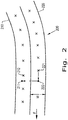
- Fig. 2 is an overhead schematic of two passes 200 traversed by the machine 100, as illustrated in Fig. 1 , according to an embodiment of the present invention.
- the two passes 200 comprise a last pass 210, a current pass 220, a current position 221, an upcoming position 222, a point on the last path 211 closest to the upcoming position 222, and a position on the last path 212 that is closest to the point on the last path 211.
- the crosses on the last path 210 represent past positions of the machine 100 at which GPS positions and associated sensor data was received and stored by the controller 160.
- the controller 160 determines, based on the current position 221, a current ground velocity and a delay time interval that is based upon how quickly header adjustments can be made, the upcoming position 222, and may further determine, based upon a width W of any pass, the point on the last path 211 closest to the upcoming position 222. For example, knowing the current position 221, the upcoming position 222 is the current position 221 plus the product of the current ground velocity and the preset delay time interval. Furthermore, the controller 160 may then determine, from the set of stored GPS positions of the last path 210, the position on the last path 212 that is closest to the point on the last path 211, which is also closest to the upcoming position 222.
- the scope of the present invention covers other methods of determining an upcoming position and a position on the last path that is closest to the upcoming position which may or may not require the use of ground velocity vectors and/or delay time intervals.
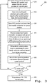
- Fig. 3 is a flow chart illustrating an exemplary method 300 performed by the controller 160 in accordance with an embodiment of the present invention.
- the controller 160 receives GPS position and associated sensor data at a current position on a current pass. For example, and in reference to Fig. 2 , when the machine 100 is located at current position 221 on a current pass 220, the controller 160 receives a GPS position from the GPS device 180 and sensor data (e.g., sensor signals from one or more cutter sensors 171 and one or more wheel sensors 172).
- sensor data e.g., sensor signals from one or more cutter sensors 171 and one or more wheel sensors 172.
- the controller 160 may re-orient the header 120 at the current position 221, based upon the sensor data received at the current position 221. For example, the controller 160 may reactively fine-tune the orientation of the header 120 based upon the sensor data currently received at the current position 221, resulting in a desired final orientation of the header 120.
- Re-orientating the header 120 includes one or more of adjusting the height, the lateral tilt, and the fore-aft tilt of the header 120, which includes activating one or more actuators 150A-150C carried by the header 120 and/or feeder 140.
- step 330 the controller 160 stores, in either a controller memory or a memory external to the controller 160, the received GPS position and the associated final orientation of the header 120 for the current position 221 of the machine 100.
- the controller 160 receives, from memory, stored final orientation of the header 120 associated with a stored GPS position on a last pass 212 that is closest in distance to an upcoming GPS position on the current pass 222.
- the controller 160 is configured to determine the upcoming GPS position on the current pass 222 based on, in one embodiment, a current GPS position 221, a current direction of motion, and a fixed length interval, or in another embodiment, based on the current GPS position 221, the current direction of motion, ground speed, and a delay time interval associated with header 120.
- the delay time interval may be dependent upon the mechanical characteristics of the header 120, and further based upon the various lengths of time required to rotate or lift/lower the header 120 from one position to another. In one embodiment, the delay time interval may be adjustable preset by the operator of the machine 100.
- the controller 160 is configured to determine the stored GPS position on the last pass 212 that is closest in distance to the determined upcoming GPS position on the current pass 222 based upon determining the stored GPS position on the last pass 212 that is closest in distance to the point 211, where the point 211 may be determined based upon a vector of width W (i.e., pass width) extending from the determined upcoming GPS position 222 in a direction perpendicular to the direction of motion of the machine 100 between GPS positions 221 and 222.
- W i.e., pass width
- the position 212 is closest to the location 211, and thus the stored position 212 is determined to be the stored GPS position of the last pass that is closest to the upcoming GPS position on the current pass 222.
- the controller 160 sends signals to one or more of the actuators 150A-150C of the actuator system 150, based upon the received stored final header orientation associated with the stored GPS position on the last pass that is closest in distance to the upcoming GPS position on the current pass, in order to begin to predictively re-orient the header 120 to a orientation that is optimal for the upcoming position 222.
- the controller 160 re-orients the header 120 to within some percentage of the received stored final header orientation (i.e., to within some percentage of the received stored final header height and/or tilt values) based upon a current ground speed of the machine 100. In one embodiment, the lower the ground speed, the smaller the percentage difference between the re-oriented header values and the received stored final header orientation values.
- step 360 the machine 100 has moved to the upcoming position 222, and the header 120 is now predictively re-oriented to within some percentage of the received stored final header orientation, which is based upon the ground speed of the machine 100, and for ease of explaining the method, the upcoming position 222 is renamed as the current position.
- step 370 the controller 160 determines whether the current pass 220 is complete. If the current pass 220 is not complete, then the method continues at step 310. If the current pass 220 is complete, then in step 380 a next pass (not shown) is initiated, and steps 310-370 are repeated for the next pass.
- the steps of the method 300 are performed by their respective controller 160 upon loading and executing software code or instructions which are tangibly stored on a tangible computer readable medium, such as on a magnetic medium, e.g., a computer hard drive, an optical medium, e.g., an optical disc, solid-state memory, e.g., flash memory, or other storage media known in the art.
- a tangible computer readable medium such as on a magnetic medium, e.g., a computer hard drive, an optical medium, e.g., an optical disc, solid-state memory, e.g., flash memory, or other storage media known in the art.
- any of the functionality performed by the controller 160 described herein, such as the method 300 is implemented in software code or instructions which are tangibly stored on a tangible computer readable medium.
- the controller 160 may perform any of the functionality of the controller 160 described herein, including any steps of the method 300 described herein.
- software code or “code” used herein refers to any instructions or set of instructions that influence the operation of a computer or controller. They may exist in a computer-executable form, such as machine code, which is the set of instructions and data directly executed by a computer's central processing unit or by a controller, a human-understandable form, such as source code, which may be compiled in order to be executed by a computer's central processing unit or by a controller, or an intermediate form, such as object code, which is produced by a compiler.
- the term "software code” or “code” also includes any human-understandable computer instructions or set of instructions, e.g., a script, that may be executed on the fly with the aid of an interpreter executed by a computer's central processing unit or by a controller.
Landscapes
- Engineering & Computer Science (AREA)
- Life Sciences & Earth Sciences (AREA)
- Environmental Sciences (AREA)
- Radar, Positioning & Navigation (AREA)
- Remote Sensing (AREA)
- General Physics & Mathematics (AREA)
- Aviation & Aerospace Engineering (AREA)
- Physics & Mathematics (AREA)
- Automation & Control Theory (AREA)
- Soil Sciences (AREA)
- Mechanical Engineering (AREA)
- Position Fixing By Use Of Radio Waves (AREA)
- Lifting Devices For Agricultural Implements (AREA)
- Vehicle Body Suspensions (AREA)
- Control Of Position, Course, Altitude, Or Attitude Of Moving Bodies (AREA)
Abstract
Description
- The present invention relates to agricultural vehicles and, more particularly, to agricultural harvesters equipped with a header.
- An agricultural harvester known as a "combine" is historically termed such because it combines multiple harvesting functions with a single harvesting unit, such as picking, threshing, separating and cleaning. A combine includes a header which removes the crop from a field, and a feeder housing which transports the crop matter into a threshing rotor. The threshing rotor rotates within a perforated housing, which may be in the form of adjustable concaves, and performs a threshing operation on the crop to remove the grain. Once the grain is threshed it falls through perforations in the concaves and is transported to a grain pan. From the grain pan the grain is cleaned using a cleaning system, and is then transported to a grain tank onboard the combine. The cleaning system includes a cleaning fan which blows air through oscillating sieves to discharge chaff and other debris toward the rear of the combine. Non-grain crop material such as straw from the threshing section proceeds through a straw chopper and out the rear of the combine. When the grain tank becomes full, the combine is positioned adjacent a vehicle into which the grain is to be unloaded, such as a semi-trailer, gravity box, straight truck, or the like; and an unloading system on the combine is actuated to transfer the grain into the vehicle.
- When a harvester is moving through the field, the header must be maintained at a certain height above the ground to harvest all the crop without damaging the header. Thus, when the terrain changes, the header must be re-positioned. In a conventional harvester, the header is re-positioned using data collected, by height and/or tilt sensors, on the current pass of the harvester through the field.
- For example, in combines with headers that are rigidly attached to the combine feeder house, the combine is typically equipped with a header height control (HHC) system which adjusts the height and tilt angle of the header relative to the ground. The HHC system is particularly important to prevent the header from contacting objects in the field as the combine harvests crop material and furthermore helps to keep the cutting apparatus of the header at a desired height relative to the ground in order to obtain the desired crop collection. Known HHC systems include an actuator linked to a frame of the header, sensors which detect the height and/or tilt of the cutting apparatus relative to the ground, and a controller which controls the actuator based on the sensed height and/or tilt of the cutting apparatus.
- One problem with conventional header control is that the system is completely reactive, relying only on data obtained from height and/or tilt sensors on the current harvesting path of the combine. Thus, when the terrain changes too quickly, the header is often not in the correct position. This may result in lost crop (e.g., header too high) or damage to the header (e.g., header too low). Additionally, because the height control system is completely reactive, ground speed of the combine is often limited by the header position and/or relief of the terrain, and thus the operator must decide upon the speed to drive the combine so as to not miss any crop and not damage the header. The conventional system thus relies to some extent upon operator judgement in selecting the correct driving speed, thereby introducing potential operator error which can decrease the efficiency of crop collection.
- What is needed in the art is a HHC system that can overcome some of the previously described disadvantages of known HHC systems.
- In accordance with an aspect of the present invention, there is provided an agricultural vehicle comprising a chassis, a header carried by the chassis, an actuator system including a plurality of actuators linked to a frame of the header and configured to adjust an orientation of the header, a GPS device configured to output a GPS position of the vehicle, and a controller. The header includes a frame and one or more sensors carried by the frame. The sensors are configured to output one or more sensor signals associated with an orientation of the header. Furthermore, the controller is electrically coupled to the one or more sensors, the actuator system, and the GPS device. At a first location on a current pass of the vehicle, the controller is configured to receive one or more sensor signals, determine a final orientation of the header based upon the received one or more sensor signals, receive a GPS position, store the final orientation and the associated GPS position in a memory, receive from the memory a final orientation of the header associated with a GPS position at a second location on a last pass that is closest in distance to a GPS position at an upcoming location on the current pass, and activate at least one actuator of the plurality of actuators to re-orient the header based upon the received final orientation of the header associated with the GPS position at the second location before the vehicle arrives at the upcoming location.
- In accordance with another aspect of the present invention, the controller is further configured to activate at least one actuator of the plurality of actuators to re-orient the header to within a percentage of the received final orientation of the header associated with the GPS position at the second location before the vehicle arrives at the upcoming location, wherein the percentage is based upon a current speed of the agricultural vehicle.
- In accordance with another aspect of the present invention, when the vehicle arrives at the upcoming location on the current pass, the controller is further configured to receive one or more second sensor signals, determine a second final orientation of the header based upon the received one or more second sensor signals, receive a second GPS position, store the second final orientation and the associated second GPS position in the memory, and activate at least one actuator of the plurality of actuators to further re-orient the header based upon the second final orientation of the header.
- An advantage of the agricultural vehicle described herein is to provide a predictive header height control system for an agricultural vehicle that more accurately positions the header into a desired position and orientation with respect to the surface of the ground.
- More specifically, the predictive HHC system of the present invention reduces the amount of reactive sensor travel by first predictively moving the sensors, based upon retrieving stored header orientation values obtained by the sensors on a last pass, before the sensors have arrived at an upcoming location in the current pass, thereby positioning the header close to its optimal settings before the header is reactively fine-tuned by utilizing newly obtained sensor data on the current path. Specifically, for large/abrupt changes (such as changes due to a terrace or water-way), the predictive HHC system more accurately positions the header such that the vehicle may be operated at a faster speed with less risk for header damage and with no loss in, or even higher, crop collection yields.
- The above-mentioned and other features and advantages of this invention, and the manner of attaining them, will become more apparent and the invention will be better understood by reference to the following description of exemplary embodiments of the invention taken in conjunction with the accompanying drawings, wherein:
-
Fig. 1 is a side view of an exemplary embodiment of an agricultural vehicle formed in accordance with the present invention; -
Fig. 2 is an exemplary embodiment of an overhead view of two paths, traversed by the agricultural vehicle illustrated inFig. 1 , formed in accordance with the present invention; and -
Fig. 3 is a flow chart illustrating an exemplary method performed by the controller of the agricultural vehicle illustrated inFig. 1 , formed in accordance with the present invention. - Corresponding reference characters indicate corresponding parts throughout the several views. The exemplifications set out herein illustrate embodiments of the invention and such exemplifications are not to be construed as limiting the scope of the invention in any manner.
- Referring now to the drawings, and more particularly to
Fig. 1 , an exemplary embodiment of an agricultural machine 100 formed in accordance with an embodiment of the present invention is shown, including a predictive header height control (HHC)system 110 operable for predictively controlling height and tilting adjustment of aheader 120 carried on afront end 131 of achassis 130 of machine 100, as machine 100 moves over aground surface 132, as denoted by arrow F. Agricultural machine 100, also referred to as an agricultural vehicle, is a typical, self-propelled combine harvester having thechassis 130 carrying a conventionally configured and operable engine and power train that drives tracks orwheels 133. The engine can power acutter 121 ofheader 120, which can include a conventionally configured and operable sickle cutter, disk cutters, or the like, as well as areel 122, and gatheringapparatus 123, which here is a draper belt system but could be an auger device, all of which are conventionally configured and operable. - A center region of
header 120 is supported on machine 10 by afeeder 140, the front end of which is movable upwardly and downwardly relative to machine 100 for setting a height, denoted by height H inFig. 1 , of thecutter 121. The cut plants will then fall onto a floor or pan ofheader 120, aided byreel 122, and pass onto gatheringapparatus 123. The cut plants are then carried byapparatus 123 to an inlet opening offeeder 140, which will induct the cut plants and carry them internally therethrough into machine 100 for processing, all in the conventional, well known manner. - To control the height, lateral tilting and fore-aft tilting of the
header 120, thechassis 130 carries anactuator system 150 withactuators frame 124 of theheader 120 and/or thefeeder 140. One or more of theactuators chassis 130, if desired. Theactuators frame 124, or a component connected to theframe 124 such as thefeeder 140, in order to lift, lower and/or tilt the header 120 (i.e., re-orient the header). Theactuator system 150 can include, for example, a height actuator 150A which is configured to vertically raise and lower theframe 124 to adjust the height of theheader 120; alateral tilt actuator 150B which is configured to adjust the lateral tilt of theframe 124, i.e., side-to-side tilting of theheader 120 relative to the forward direction F; and a fore-aft actuator 150C which is configured to adjust the fore-aft tilt of theframe 124, i.e., tilting of theheader 120 front-to-back relative to the forward direction F. It should be appreciated that reference to "tilt" and "tilting" of theheader 120 herein can refer to both lateral and fore-aft tilting, unless only one of the types of tilt is specified. Theactuator system 150 is electrically coupled to acontroller 160 which sends signals to theactuators actuators controller 160 may be mounted to a surface located within acab 190 of the machine 100, such as aback wall 192 of thecab 190, for example. As used herein, thecontroller 160 is "electrically coupled" to theactuator system 150 in the sense that thecontroller 160 is electrically coupled to eachactuator actuator system 150 so thecontroller 160 can activate eachactuator 150A, 150B, 3150C. Theactuator system 150 andcontroller 160 can be configured so thecontroller 160 can activate eachactuator actuator system 150 independently of the other actuators. Thecontroller 160 can include, for example, an electrical processing circuit or central processing unit and memory that allow thecontroller 160 to send and receive electrical signals to control various components of the vehicle 100, which will be described further herein. In the case of pneumatic or hydraulic cylinders, thecontroller 160 can control one or more valves (not shown) of the cylinder to fill or drain fluid from within the cylinder, as is known. It should be appreciated that other types ofactuators controller 160 will control the mechanism that causes extension and retraction of theactuators actuator system 150 is shown and described as including threeactuators actuator system 150 can have two actuators or may have more than three actuators to control positioning of theheader 120 via positioning of theframe 124. - The
header 120 may also include one ormore sensors 170 electrically coupled to thecontroller 160, that indicate, either individually or in some combination, height of the header 120 (e.g., height H of the cutter 121) above theground surface 132, lateral (i.e., side-to-side) tilting of theheader 120 with respect to the forward direction F, and fore-aft (front-to-back) tilting of theheader 120 with respect to the forward direction F, or in other words, orientation of theheader 120 with respect to theground surface 132 or with respect to the forward direction F. - For example, in one embodiment the
controller 160 is electrically coupled to acutter sensor 171 associated with thecutter 121 of theheader 120. Thecutter sensor 171 detects the height H of thecutter 121 relative to theground surface 132 by contacting theground surface 132 and flexing. Depending on the flexion of thecutter sensor 171, thecutter sensor 171 sends a cutter height signal, also referred to as a cutter sensor signal, to thecontroller 160 which has a magnitude indicating the height H of thecutter 121 relative to theground surface 132. Thecontroller 160 can maintain thecutter 121 at a desired height H relative to theground surface 132 by comparing a difference between the magnitude of the cutter height signal and a stored pre-determined height threshold value, and activating one or more of theactuators frame 124, based on the difference, so that thecutter 121 assumes the desired height (i.e., orientation) relative to theground surface 132. - On
flat ground surfaces 132, such as theground surface 132 shown inFig. 1 , thecutter sensor 171 is typically sufficient to accurately control the height H of thecutter 121. However, when the ground surface is not level, such as when the vehicle 100 is traveling across non-flat terrain, such as a slope, certain instances can arise where thecutter sensor 171 may not convey sufficient information to thecontroller 160 to accurately control the height H and tilt angle of theheader 120. To better follow the contour of such ground surfaces, and in another embodiment of the invention, theheader 120 may optionally include awheel sensor 172 which is associated with agauge wheel 173 which is carried by theframe 124 of theheader 120 behind thecutter 121. Thewheel sensor 172 can include amount 174 connected to theframe 124 of theheader 120 and anarm 175 connecting thegauge wheel 173 to themount 174. To allow thegauge wheel 173 to adjust to changes in height of the terrain as the vehicle 100 travels, thearm 175 can be pivotally connected to themount 174 so thegauge wheel 173 can pivot relative to themount 174 during travel. To keep thegauge wheel 173 engaged with theground surface 132 as the vehicle 100 travels in the forward direction F, aspring 176 can be connected to thearm 175 that biases thegauge wheel 173 toward theground surface 132. Thewheel sensor 172 is configured to output a wheel position signal, also referred to as a wheel sensor signal, to thecontroller 160 which corresponds to a position of thegauge wheel 173, either linear or angular, relative to themount 174. - The
cutter 121, which is carried at a front (relative to the forward direction F) of theframe 124, and thegauge wheel 173, carried behind thecutter 121, have a separation distance relative to the forward direction F. Due to this separation distance, thecutter 121 andgauge wheel 173 can be traveling on two different grades (not shown) of the ground surface, or in other words, can be traveling over a terrain irregularity (i.e., a non-flat ground surface). Thecontroller 160 may compare, for example, a difference between a received cutter height signal to a received wheel angle signal, wherein a magnitude of such a difference indicates the strength of the terrain irregularity. For example, if the received cutter height signal is large and the received wheel angle signal is very small or zero, then thecutter 121 is positioned above a steep incline while the gauge wheel is still on a flat surface, and based upon the large magnitude of the difference, thecontroller 160 determines the proper corrective action that should be taken by the one or more actuators to prevent a front portion of theheader 120 from digging into the steep incline of the terrain. For example, thecontroller 160 may determine which of saidactuators header 120 follows the contour of theground surface 132. In one embodiment, thecontroller 160 may activate one or more ofactuators header 120. - Further, the
controller 160 can be configured to take other factors into account, such as a speed of the vehicle 100 and a rate of change in the gauge wheel angle, to determine which of the actuators 150A, 150B, 150C to activate in order to avoid damage to theheader 120. - Although the embodiment illustrated by
Fig. 1 depicts acutter sensor 171 combined with anoptional wheel sensor 172, the scope of the present invention covers two or more cutter height sensors, configured as the above-describedcutter sensor 171 and attached at various points on theframe 124 of theheader 120, and two or moreoptional wheel sensors 172 attached at various points on theframe 124 of theheader 120. For example, in one embodiment of the present invention, theheader 120 includes twogauge wheels 173 with two associatedwheel sensors 172. Thewheel sensors 172 may be mounted on opposite sides of theframe 124 along a direction transverse to the forward direction F, and they may be referred to as left and right wheel sensors and left and right gauge wheels with respect to the forward direction F. The twowheel sensors 172 are configured to independently output corresponding wheel position signals to thecontroller 160 which corresponds to positions of the two associatedgauge wheels 173, either linear or angular, relative to theirrespective mounts 174. Thus, thecontroller 160 may determine the lateral tilt of theheader 120 by comparing the difference between the two wheel position signals, and based at least upon this difference, may activate one or more of the actuators 150A, 150B, 150C to tilt (and optionally in addition, may lower or raise) theframe 124 so that theheader 120 andcutter 121 assume a desired orientation relative to theground surface 132. - As discussed above, the
controller 160 is electrically coupled to one or more sensors (e.g., cutter sensor(s) 171 and optional wheel sensor(s) 172) and theactuator system 150. In addition, and in a further embodiment of the invention, thecontroller 160 is electrically coupled to a global positioning system (GPS)device 180 carried by thechassis 130, preferable on an outside surface of thechassis 130, such as atop surface 194 of thecab 190. TheGPS device 180 is any conventional global positioning system device configured to use satellite signals for determining a current global position of thedevice 180, and thus, the position of the machine 100. - In one embodiment of the present invention, the
controller 160 is configured to receive, from theGPS device 180, a current position of the machine 100 as it harvests the crops, as well as associated sensor data comprising the sensor signals obtained by the one or more sensors at the current position of the machine 100. In addition, thecontroller 160 is configured to determine a preferred orientation of the header 120 (e.g., the height, fore-aft tilt and/or lateral tilt) based upon the received sensor data, and actuate the actuators accordingly to position theheader 120 in the determined preferred orientation. Furthermore, thecontroller 160 is configured to store, in controller memory, for example, each current position of the machine 100 and the associated preferred orientation of theheader 120, also referred to simply as the orientation of theheader 120. In another embodiment of the invention, thecontroller 160 may also either determine, from subsequently received GPS signals, a current ground speed of the machine 100, or receive from theGPS device 180 the current ground speed of the machine 100, and store the ground speed associated with the current position and the associated orientation of theheader 120. - In another embodiment of the invention, as described more fully below in conjunction with
Figs. 2-3 , thecontroller 160 is configured to, on any given pass of the machine 100 through the field, receive from controller memory (not shown) past orientation values of theheader 120 associated with a GPS position from a neighboring last pass to be used to initiate adjusting the header 120 (via the actuators) on a given current pass before the machine 100 reaches a GPS position on the current pass that is closest to the GPS position of the machine 100 on the neighboring last pass. In other words, thecontroller 160 of thepredictive HHC system 110 of the present invention enables theheader 120 to move towards an orientation (defined by height and tilt values) recorded in a last (i.e., previous) pass having a GPS position that is closest in distance to an upcoming GPS position in the current pass before the machine 100 (e.g., the header 120) reaches that position in the current pass. That is, thecontroller 160, using header orientation values recorded at a location in a last pass, predicts the orientation of the header at a future location in a current pass, where the spatial difference between the two locations, defined by the GPS coordinates of the two locations, is at a minimum, or at least close to a minimum. - In another embodiment of the invention, the
controller 160, upon receiving the stored orientation of theheader 120 from the last pass, predictively begins to move theheader 120 such that theheader 120 is within a certain percentage of the stored orientation when the machine 100 arrives (or slightly before when the machine 100 arrives) at the upcoming location in the current pass. Furthermore, when the machine 100 arrives (or slightly before when the machine 100 arrives) at the upcoming location in the current pass, thecontroller 160 uses newly received sensor data to further orientate the header 120 (i.e., to fine-tune the orientation of the header 120) in a reactive manner. Thus, in this embodiment of the invention, thepredictive HHC system 110 uses a predictive/reactive algorithm to adjust (i.e., re-position or re-orientate) theheader 120 as the machine 100 approaches an upcoming location in a current pass, in which the predictive component is based upon stored orientation values of theheader 120 recorded in a last neighboring pass that are used to begin moving theheader 120 to within some given percentage of the stored orientation values of theheader 120, and in which the reactive component is based upon current sensor data (i.e., sensor data obtained (and subsequently stored) on the current pass at or near the upcoming location) to fine-tune the orientation of theheader 120, such that theheader 120 is correctly positioned when the machine 100 arrives at the upcoming location. - In another embodiment of the invention, the
controller 160, upon receiving the stored orientation values of the header 120 (also referred to as the stored orientation of the header 120) from the last pass, predictively moves theheader 120 to within a certain percentage of the stored orientation values, where the certain percentage is based upon current ground speed of the machine 100. For example, in an exemplary embodiment, at slower ground speeds thepredictive HHC system 110 comprises a larger predictive component/reactive component ratio when compared to the predictive component/reactive component ratio employed at faster ground speeds. For example, at a given first ground speed, thepredictive HHC system 110 may be mostly predictive, predictively moving theheader 120 to within, for example, 10% of the tilt and height orientation values associated with a GPS position of a last pass that is nearest to an upcoming GPS position of the current pass, with any remaining adjustment (i.e., fine-tune adjustment) to the orientation of theheader 120 being based upon currently (i.e., newly) obtained sensor data at (or nearly at) the upcoming position. However, at a given second ground speed, which is faster than the first ground speed, thepredictive HHC system 110 may be less predictive, predictively moving theheader 120 to within, for example, 20% of the tilt and height orientation values associated with a GPS position of a last pass that is nearest to an upcoming GPS position of the current pass, with any remaining adjustment to the orientation of theheader 120 being based upon currently (i.e., newly) obtained sensor data at (or nearly at) the upcoming position. - In another embodiment of the invention, an operator of the machine 100 may adjust the settings of the controller 160 (via, for example, a controller user interface (not shown)) to set a correlation between ground speed and the percentage of predictivity employed by the
predictive HHC system 110. For example, as discussed above, at higher ground speeds thecontroller 160 may be set to employ a smaller percentage of predictivity (e.g., operator setscontroller 160 to re-positioning theheader 120 to within 30% of stored last pass orientation values) and at lower ground speeds thecontroller 160 may be set to employ a larger percentage of predictivity (e.g., operator setscontroller 160 to re-positioning theheader 120 to within 5% of stored last pass orientation values). In this manner, an operator may tailor height control of theheader 120, also referred to as orientation control of theheader 120, to field conditions, header characteristics and acceptable crop loss, for example. -
Fig. 2 is an overhead schematic of twopasses 200 traversed by the machine 100, as illustrated inFig. 1 , according to an embodiment of the present invention. The twopasses 200 comprise alast pass 210, acurrent pass 220, acurrent position 221, anupcoming position 222, a point on thelast path 211 closest to theupcoming position 222, and a position on thelast path 212 that is closest to the point on thelast path 211. The crosses on thelast path 210 represent past positions of the machine 100 at which GPS positions and associated sensor data was received and stored by thecontroller 160. In one embodiment of the invention, while at thecurrent position 221, thecontroller 160 determines, based on thecurrent position 221, a current ground velocity and a delay time interval that is based upon how quickly header adjustments can be made, theupcoming position 222, and may further determine, based upon a width W of any pass, the point on thelast path 211 closest to theupcoming position 222. For example, knowing thecurrent position 221, theupcoming position 222 is thecurrent position 221 plus the product of the current ground velocity and the preset delay time interval. Furthermore, thecontroller 160 may then determine, from the set of stored GPS positions of thelast path 210, the position on thelast path 212 that is closest to the point on thelast path 211, which is also closest to theupcoming position 222. The scope of the present invention covers other methods of determining an upcoming position and a position on the last path that is closest to the upcoming position which may or may not require the use of ground velocity vectors and/or delay time intervals. -
Fig. 3 is a flow chart illustrating anexemplary method 300 performed by thecontroller 160 in accordance with an embodiment of the present invention. Instep 310, thecontroller 160 receives GPS position and associated sensor data at a current position on a current pass. For example, and in reference toFig. 2 , when the machine 100 is located atcurrent position 221 on acurrent pass 220, thecontroller 160 receives a GPS position from theGPS device 180 and sensor data (e.g., sensor signals from one ormore cutter sensors 171 and one or more wheel sensors 172). - In
step 320, thecontroller 160 may re-orient theheader 120 at thecurrent position 221, based upon the sensor data received at thecurrent position 221. For example, thecontroller 160 may reactively fine-tune the orientation of theheader 120 based upon the sensor data currently received at thecurrent position 221, resulting in a desired final orientation of theheader 120. Re-orientating theheader 120 includes one or more of adjusting the height, the lateral tilt, and the fore-aft tilt of theheader 120, which includes activating one or more actuators 150A-150C carried by theheader 120 and/orfeeder 140. - In
step 330, thecontroller 160 stores, in either a controller memory or a memory external to thecontroller 160, the received GPS position and the associated final orientation of theheader 120 for thecurrent position 221 of the machine 100. - In
step 340, and while still at thecurrent position 221, thecontroller 160 receives, from memory, stored final orientation of theheader 120 associated with a stored GPS position on alast pass 212 that is closest in distance to an upcoming GPS position on thecurrent pass 222. For example, thecontroller 160 is configured to determine the upcoming GPS position on thecurrent pass 222 based on, in one embodiment, acurrent GPS position 221, a current direction of motion, and a fixed length interval, or in another embodiment, based on thecurrent GPS position 221, the current direction of motion, ground speed, and a delay time interval associated withheader 120. The delay time interval may be dependent upon the mechanical characteristics of theheader 120, and further based upon the various lengths of time required to rotate or lift/lower theheader 120 from one position to another. In one embodiment, the delay time interval may be adjustable preset by the operator of the machine 100. - In another embodiment, the
controller 160 is configured to determine the stored GPS position on thelast pass 212 that is closest in distance to the determined upcoming GPS position on thecurrent pass 222 based upon determining the stored GPS position on thelast pass 212 that is closest in distance to thepoint 211, where thepoint 211 may be determined based upon a vector of width W (i.e., pass width) extending from the determinedupcoming GPS position 222 in a direction perpendicular to the direction of motion of the machine 100 betweenGPS positions position 212 is closest to thelocation 211, and thus the storedposition 212 is determined to be the stored GPS position of the last pass that is closest to the upcoming GPS position on thecurrent pass 222. - In
step 350, and while still at thecurrent position 221, thecontroller 160 sends signals to one or more of the actuators 150A-150C of theactuator system 150, based upon the received stored final header orientation associated with the stored GPS position on the last pass that is closest in distance to the upcoming GPS position on the current pass, in order to begin to predictively re-orient theheader 120 to a orientation that is optimal for theupcoming position 222. In one embodiment of the invention, and as discussed above in conjunction withFig. 2 , thecontroller 160 re-orients theheader 120 to within some percentage of the received stored final header orientation (i.e., to within some percentage of the received stored final header height and/or tilt values) based upon a current ground speed of the machine 100. In one embodiment, the lower the ground speed, the smaller the percentage difference between the re-oriented header values and the received stored final header orientation values. - In
step 360, the machine 100 has moved to theupcoming position 222, and theheader 120 is now predictively re-oriented to within some percentage of the received stored final header orientation, which is based upon the ground speed of the machine 100, and for ease of explaining the method, theupcoming position 222 is renamed as the current position. - In
step 370, thecontroller 160 determines whether thecurrent pass 220 is complete. If thecurrent pass 220 is not complete, then the method continues atstep 310. If thecurrent pass 220 is complete, then in step 380 a next pass (not shown) is initiated, and steps 310-370 are repeated for the next pass. - It is to be understood that the steps of the
method 300 are performed by theirrespective controller 160 upon loading and executing software code or instructions which are tangibly stored on a tangible computer readable medium, such as on a magnetic medium, e.g., a computer hard drive, an optical medium, e.g., an optical disc, solid-state memory, e.g., flash memory, or other storage media known in the art. Thus, any of the functionality performed by thecontroller 160 described herein, such as themethod 300, is implemented in software code or instructions which are tangibly stored on a tangible computer readable medium. Upon loading and executing such software code or instructions by thecontroller 160, thecontroller 160 may perform any of the functionality of thecontroller 160 described herein, including any steps of themethod 300 described herein. - The term "software code" or "code" used herein refers to any instructions or set of instructions that influence the operation of a computer or controller. They may exist in a computer-executable form, such as machine code, which is the set of instructions and data directly executed by a computer's central processing unit or by a controller, a human-understandable form, such as source code, which may be compiled in order to be executed by a computer's central processing unit or by a controller, or an intermediate form, such as object code, which is produced by a compiler. As used herein, the term "software code" or "code" also includes any human-understandable computer instructions or set of instructions, e.g., a script, that may be executed on the fly with the aid of an interpreter executed by a computer's central processing unit or by a controller.
- While this invention has been described with respect to at least one embodiment, the present invention can be further modified within the scope of this disclosure. This application is therefore intended to cover any variations, uses, or adaptations of the invention using its general principles. Further, this application is intended to cover such departures from the present disclosure as come within known or customary practice in the art to which this invention pertains and which fall within the limits of the appended claims.
Claims (10)
- An agricultural vehicle (100), comprising:a chassis (130);a header (120) carried by said chassis (130), said header (120) including:
a frame (124), andone or more sensors (170) carried by said frame (124), said one or more sensors (170) configured to output one or more sensor signals associated with an orientation of said header (120);an actuator system (150) including a plurality of actuators (150A, 150B, 150C) linked to said frame (124) and configured to adjust the orientation of said header (120);a GPS device (180) configured to output a GPS position of said vehicle (100); and
a controller (160) electrically coupled to said one or more sensors (170), said actuator system (150), and said GPS device (180),
characterized in that
said controller (160) is configured to, at a first location (221) on a current pass (220) of said vehicle (100):receive, from said one or more sensors (170), one or more sensor signals;determine a final orientation of said header (120) based upon said received one or more sensor signals;receive a GPS position;
store said final orientation and said associated GPS position in a memory;
receive, from said memory, a final orientation of said header (120) associated with a GPS position at a second location (212) on a last pass (210) that is closest in distance to a GPS position at an upcoming location (222) on the current pass (220); and
activate at least one actuator of said plurality of actuators (150A, 150B, 150C) to re-orient said header (120) based upon said received final orientation of said header (120) associated with said GPS position at said second location (212) before said vehicle (100) arrives at said upcoming location (222). - The agricultural vehicle (100) according to claim 1, wherein said header (120) comprises a cutter (121), and said one or more sensors (170) comprises one or more cutter sensors (171) configured to generate one or more cutter sensor signals for indicating a height of the cutter (121) from a surface (132) of the current pass (220).
- The agricultural vehicle (100) according to claim 2, wherein said header (120) comprises one or more gauge wheels (173), and wherein said one or more sensors (170) comprises one or more wheel sensors (172) configured to generate one or more wheel sensor signals.
- The agricultural vehicle (100) according to claim 3, wherein the controller (160) is further configured to determine a fore-aft tilt of the header (120) based upon the one or more wheel sensor signals and the one or more cutter sensor signals.
- The agricultural vehicle (100) according to claims 3 or 4, wherein the controller (160) is further configured to determine a lateral tilt of the header (120) based upon at least two wheel sensor signals associated with at least two wheel sensors (172).
- The agricultural vehicle (100) according to claim 1, wherein said orientation of said header (120) comprises a height of said header (120) from a surface (132) of said current pass (220), a fore-aft tilt of said header (120), and a lateral tilt of said header (120).
- The agricultural vehicle (100) according to any preceding claims, wherein the controller (160) is configured to determine said upcoming location (222) on said current pass (220) based upon said current location (221), a current ground velocity of said machine (100), and a delay time interval associated with said header (120).
- The agricultural vehicle (100) according to any preceding claims, wherein the controller (160) is further configured to activate at least one actuator of said plurality of actuators (150A, 150B, 150C) to re-orient said header (120) to within a percentage of said received final orientation of said header (120) associated with said GPS position at said second location (212) before said vehicle (100) arrives at said upcoming location (222), wherein said percentage is based upon a current speed of said agricultural vehicle (100).
- The agricultural vehicle (100) according to claim 8, wherein said received final orientation of said header (120) comprises header height and tilt values, and wherein said percentage of said received final orientation of said header (120) comprises said percentage of said header height and tilt values.
- The agricultural vehicle (100) according to claims 8 or 9, wherein said controller (160) is further configured to, when the vehicle (100) arrives at said upcoming location (222) on said current pass (220):receive, from said one or more sensors (170), one or more second sensor signals;determine a second final orientation of said header (120) based upon said received one or more second sensor signals;receive a second GPS position;store said second final orientation and said associated second GPS position in said memory; andactivate at least one actuator of said plurality of actuators (150A, 150B, 150C) to further re-orient said header (120) based upon said second final orientation of said header (120).
Applications Claiming Priority (1)
| Application Number | Priority Date | Filing Date | Title |
|---|---|---|---|
| US15/882,740 US10687466B2 (en) | 2018-01-29 | 2018-01-29 | Predictive header height control system |
Publications (2)
| Publication Number | Publication Date |
|---|---|
| EP3516942A1 true EP3516942A1 (en) | 2019-07-31 |
| EP3516942B1 EP3516942B1 (en) | 2020-08-26 |
Family
ID=65243373
Family Applications (1)
| Application Number | Title | Priority Date | Filing Date |
|---|---|---|---|
| EP19154137.4A Active EP3516942B1 (en) | 2018-01-29 | 2019-01-29 | Predictive header height control system |
Country Status (5)
| Country | Link |
|---|---|
| US (1) | US10687466B2 (en) |
| EP (1) | EP3516942B1 (en) |
| AU (1) | AU2019200539B2 (en) |
| BR (1) | BR102019001689B1 (en) |
| CA (1) | CA3029608A1 (en) |
Cited By (3)
| Publication number | Priority date | Publication date | Assignee | Title |
|---|---|---|---|---|
| CN110809995A (en) * | 2019-10-09 | 2020-02-21 | 江苏大学 | Full swath control method and system for crawler-type combine harvester |
| WO2021047799A1 (en) * | 2019-09-13 | 2021-03-18 | Agco International Gmbh | Harvesting headers having leading sensors, agricultural machines carrying such headers, and related methods |
| US20230134768A1 (en) * | 2020-05-29 | 2023-05-04 | Cnh Industrial America Llc | Header height control for combine harvester |
Families Citing this family (75)
| Publication number | Priority date | Publication date | Assignee | Title |
|---|---|---|---|---|
| US20190335661A1 (en) * | 2018-05-07 | 2019-11-07 | CNH Industrial America, LLC | Method and system for controlling the height of an agricultural implement relative to the ground |
| US11079725B2 (en) | 2019-04-10 | 2021-08-03 | Deere & Company | Machine control using real-time model |
| US11672203B2 (en) | 2018-10-26 | 2023-06-13 | Deere & Company | Predictive map generation and control |
| US11957072B2 (en) | 2020-02-06 | 2024-04-16 | Deere & Company | Pre-emergence weed detection and mitigation system |
| US12069978B2 (en) | 2018-10-26 | 2024-08-27 | Deere & Company | Predictive environmental characteristic map generation and control system |
| US11240961B2 (en) | 2018-10-26 | 2022-02-08 | Deere & Company | Controlling a harvesting machine based on a geo-spatial representation indicating where the harvesting machine is likely to reach capacity |
| US11641800B2 (en) | 2020-02-06 | 2023-05-09 | Deere & Company | Agricultural harvesting machine with pre-emergence weed detection and mitigation system |
| US11178818B2 (en) | 2018-10-26 | 2021-11-23 | Deere & Company | Harvesting machine control system with fill level processing based on yield data |
| US11589509B2 (en) | 2018-10-26 | 2023-02-28 | Deere & Company | Predictive machine characteristic map generation and control system |
| US11653588B2 (en) | 2018-10-26 | 2023-05-23 | Deere & Company | Yield map generation and control system |
| US11467605B2 (en) | 2019-04-10 | 2022-10-11 | Deere & Company | Zonal machine control |
| US12150408B2 (en) * | 2018-11-16 | 2024-11-26 | Cnh Industrial America Llc | Self-supporting harvester header system |
| US11234366B2 (en) | 2019-04-10 | 2022-02-01 | Deere & Company | Image selection for machine control |
| US11778945B2 (en) | 2019-04-10 | 2023-10-10 | Deere & Company | Machine control using real-time model |
| US11246259B2 (en) * | 2019-04-26 | 2022-02-15 | Deere & Company | Locking assembly for agricultural combine harvesting head |
| US11659785B2 (en) * | 2019-10-23 | 2023-05-30 | Cnh Industrial America Llc | Method and system for controlling the height of an agricultural implement relative to the ground |
| US11375664B2 (en) * | 2019-11-16 | 2022-07-05 | Cnh Industrial America Llc | Agricultural header with linearly displaceable flex arms |
| US11758846B2 (en) * | 2019-12-23 | 2023-09-19 | Cnh Industrial America Llc | Header control system to adjust a header of a harvester based on sensor information |
| US12225846B2 (en) * | 2020-02-06 | 2025-02-18 | Deere & Company | Machine control using a predictive map |
| US12329148B2 (en) | 2020-02-06 | 2025-06-17 | Deere & Company | Predictive weed map and material application machine control |
| US12035648B2 (en) | 2020-02-06 | 2024-07-16 | Deere & Company | Predictive weed map generation and control system |
| US12016257B2 (en) | 2020-02-19 | 2024-06-25 | Sabanto, Inc. | Methods for detecting and clearing debris from planter gauge wheels, closing wheels and seed tubes |
| US11477940B2 (en) | 2020-03-26 | 2022-10-25 | Deere & Company | Mobile work machine control based on zone parameter modification |
| US11669093B2 (en) * | 2020-03-26 | 2023-06-06 | Deere & Company | Mobile work machine control based on control zone map data |
| BR112022021615A2 (en) * | 2020-04-29 | 2022-12-06 | Cnh Ind America Llc | SYSTEM AND METHOD FOR CONTROLLING THE HARVEST IMPLEMENT OPERATION OF AN AGRICULTURAL HARVESTER BASED ON TILT ACTUATOR STRENGTH |
| US12461083B2 (en) | 2020-08-03 | 2025-11-04 | Sabanto, Inc. | Methods for improved agricultural procedures |
| US11474523B2 (en) | 2020-10-09 | 2022-10-18 | Deere & Company | Machine control using a predictive speed map |
| US11845449B2 (en) | 2020-10-09 | 2023-12-19 | Deere & Company | Map generation and control system |
| US12419220B2 (en) * | 2020-10-09 | 2025-09-23 | Deere & Company | Predictive map generation and control system |
| US11635765B2 (en) | 2020-10-09 | 2023-04-25 | Deere & Company | Crop state map generation and control system |
| US11849672B2 (en) | 2020-10-09 | 2023-12-26 | Deere & Company | Machine control using a predictive map |
| US11592822B2 (en) | 2020-10-09 | 2023-02-28 | Deere & Company | Machine control using a predictive map |
| US12069986B2 (en) | 2020-10-09 | 2024-08-27 | Deere & Company | Map generation and control system |
| US11849671B2 (en) | 2020-10-09 | 2023-12-26 | Deere & Company | Crop state map generation and control system |
| US12550802B2 (en) | 2020-10-08 | 2026-02-17 | Deere & Company | Predictive machine characteristic map generation and control system |
| US11844311B2 (en) | 2020-10-09 | 2023-12-19 | Deere & Company | Machine control using a predictive map |
| US11889788B2 (en) | 2020-10-09 | 2024-02-06 | Deere & Company | Predictive biomass map generation and control |
| US11983009B2 (en) | 2020-10-09 | 2024-05-14 | Deere & Company | Map generation and control system |
| US12178158B2 (en) | 2020-10-09 | 2024-12-31 | Deere & Company | Predictive map generation and control system for an agricultural work machine |
| US12013245B2 (en) | 2020-10-09 | 2024-06-18 | Deere & Company | Predictive map generation and control system |
| US11927459B2 (en) | 2020-10-09 | 2024-03-12 | Deere & Company | Machine control using a predictive map |
| US20220110258A1 (en) | 2020-10-09 | 2022-04-14 | Deere & Company | Map generation and control system |
| US11675354B2 (en) | 2020-10-09 | 2023-06-13 | Deere & Company | Machine control using a predictive map |
| US11825768B2 (en) | 2020-10-09 | 2023-11-28 | Deere & Company | Machine control using a predictive map |
| US11874669B2 (en) | 2020-10-09 | 2024-01-16 | Deere & Company | Map generation and control system |
| US20220110238A1 (en) | 2020-10-09 | 2022-04-14 | Deere & Company | Machine control using a predictive map |
| US12386354B2 (en) | 2020-10-09 | 2025-08-12 | Deere & Company | Predictive power map generation and control system |
| US11650587B2 (en) | 2020-10-09 | 2023-05-16 | Deere & Company | Predictive power map generation and control system |
| US11871697B2 (en) | 2020-10-09 | 2024-01-16 | Deere & Company | Crop moisture map generation and control system |
| US11895948B2 (en) | 2020-10-09 | 2024-02-13 | Deere & Company | Predictive map generation and control based on soil properties |
| US11864483B2 (en) | 2020-10-09 | 2024-01-09 | Deere & Company | Predictive map generation and control system |
| US11711995B2 (en) | 2020-10-09 | 2023-08-01 | Deere & Company | Machine control using a predictive map |
| US11946747B2 (en) | 2020-10-09 | 2024-04-02 | Deere & Company | Crop constituent map generation and control system |
| US12422847B2 (en) | 2020-10-09 | 2025-09-23 | Deere & Company | Predictive agricultural model and map generation |
| US11727680B2 (en) | 2020-10-09 | 2023-08-15 | Deere & Company | Predictive map generation based on seeding characteristics and control |
| US11889787B2 (en) | 2020-10-09 | 2024-02-06 | Deere & Company | Predictive speed map generation and control system |
| US12250905B2 (en) | 2020-10-09 | 2025-03-18 | Deere & Company | Machine control using a predictive map |
| US12127500B2 (en) | 2021-01-27 | 2024-10-29 | Deere & Company | Machine control using a map with regime zones |
| US11963480B2 (en) | 2021-02-03 | 2024-04-23 | Cnh Industrial America Llc | Header fore/aft tilt control for combine harvester |
| US11944035B2 (en) | 2021-05-05 | 2024-04-02 | Cnh Industrial America Llc | System and method for controlling harvesting implement height of an agricultural harvester based on error signal frequency components |
| CN113519273A (en) * | 2021-07-12 | 2021-10-22 | 中国铁建重工集团股份有限公司 | Header mechanism, profiling control method and profiling control system |
| DE102021119897A1 (en) * | 2021-07-30 | 2023-02-02 | Claas Selbstfahrende Erntemaschinen Gmbh | Agricultural machine with anti-vibration front attachment |
| US12229886B2 (en) | 2021-10-01 | 2025-02-18 | Deere & Company | Historical crop state model, predictive crop state map generation and control system |
| US12310286B2 (en) | 2021-12-14 | 2025-05-27 | Deere & Company | Crop constituent sensing |
| US12302791B2 (en) | 2021-12-20 | 2025-05-20 | Deere & Company | Crop constituents, predictive mapping, and agricultural harvester control |
| US12245549B2 (en) | 2022-01-11 | 2025-03-11 | Deere & Company | Predictive response map generation and control system |
| US12082531B2 (en) | 2022-01-26 | 2024-09-10 | Deere & Company | Systems and methods for predicting material dynamics |
| US12520759B2 (en) | 2022-01-26 | 2026-01-13 | Deere & Company | Systems and methods for predicting material dynamics |
| JP7843579B2 (en) * | 2022-04-04 | 2026-04-10 | 日立建機株式会社 | Working machinery |
| US12295288B2 (en) | 2022-04-05 | 2025-05-13 | Deere &Company | Predictive machine setting map generation and control system |
| US12284934B2 (en) | 2022-04-08 | 2025-04-29 | Deere & Company | Systems and methods for predictive tractive characteristics and control |
| US12358493B2 (en) | 2022-04-08 | 2025-07-15 | Deere & Company | Systems and methods for predictive power requirements and control |
| US12298767B2 (en) | 2022-04-08 | 2025-05-13 | Deere & Company | Predictive material consumption map and control |
| US12582035B2 (en) | 2022-04-08 | 2026-03-24 | Deere & Company | Systems and methods for predictive power requirements and control |
| US12058951B2 (en) | 2022-04-08 | 2024-08-13 | Deere & Company | Predictive nutrient map and control |
Citations (5)
| Publication number | Priority date | Publication date | Assignee | Title |
|---|---|---|---|---|
| US5704200A (en) * | 1995-11-06 | 1998-01-06 | Control Concepts, Inc. | Agricultural harvester ground tracking control system and method using fuzzy logic |
| US5995895A (en) * | 1997-07-15 | 1999-11-30 | Case Corporation | Control of vehicular systems in response to anticipated conditions predicted using predetermined geo-referenced maps |
| CA2665589A1 (en) * | 2009-05-08 | 2010-11-08 | Macdon Industries Ltd. | Combine header with gauge wheels to control cut height |
| WO2015012774A1 (en) * | 2013-07-25 | 2015-01-29 | TÜMSAŞ TEKNOLOJlK ENDÜSTRIYEL BILGISAYAR ÜRLÜNLERI MÜHENDISLIK VE PAZARLAMA A.Ş. | A yield monitoring system for the combine harvesters |
| US20170311541A1 (en) * | 2016-05-02 | 2017-11-02 | Cnh Industrial America Llc | Programmable one-touch raise feature for an agricultural harvester such as a windrower |
Family Cites Families (25)
| Publication number | Priority date | Publication date | Assignee | Title |
|---|---|---|---|---|
| US5931882A (en) | 1993-07-29 | 1999-08-03 | Raven Industries | Combination grid recipe and depth control system |
| US6044316A (en) * | 1994-12-30 | 2000-03-28 | Mullins; Donald B. | Method and apparatus for navigating a remotely guided brush cutting, chipping and clearing apparatus |
| US6377881B1 (en) * | 1994-12-30 | 2002-04-23 | Donald B. Mullins | GPS guided ground-clearing apparatus and method |
| US6615570B2 (en) | 2001-06-28 | 2003-09-09 | Deere & Company | Header position control with forward contour prediction |
| EP3404505B1 (en) | 2006-03-17 | 2023-12-06 | iRobot Corporation | Lawn care robot |
| US9615501B2 (en) | 2007-01-18 | 2017-04-11 | Deere & Company | Controlling the position of an agricultural implement coupled to an agricultural vehicle based upon three-dimensional topography data |
| US8145390B2 (en) * | 2007-04-26 | 2012-03-27 | Cnh America Llc | Swath finder feature integrated with multipurpose display |
| US20110160968A1 (en) | 2009-12-29 | 2011-06-30 | Agco Corporation | Work implement control based on worked area |
| BE1019422A3 (en) * | 2010-07-14 | 2012-07-03 | Cnh Belgium Nv | METHOD AND APPARATUS FOR PREDICTIVE CONTROL OF AN AGRICULTURAL VEHICLE SYSTEM. |
| WO2012134723A2 (en) * | 2011-03-31 | 2012-10-04 | Ag Leader Technology | Combine bin level monitoring system |
| EP2679085A1 (en) | 2012-06-26 | 2014-01-01 | Norac Systems International Inc. | Height control |
| US8942893B2 (en) | 2012-09-07 | 2015-01-27 | Trimble Navigation Limited | Predictive boom shape adjustment |
| EP2798928B1 (en) * | 2013-04-29 | 2024-02-07 | CLAAS E-Systems GmbH | Operating system for and method of operating an automatic guidance system of an agricultural vehicle |
| US20160360697A1 (en) * | 2013-09-03 | 2016-12-15 | Agco Corporation | System and method for automatically changing machine control state |
| DE102014208070A1 (en) | 2014-04-29 | 2015-12-17 | Deere & Company | The vehicle dynamics taking into account control system for position control of a device for an agricultural work vehicle |
| US9807933B2 (en) | 2014-10-20 | 2017-11-07 | Cnh Industrial America Llc | Sensor equipped agricultural harvester |
| US9693502B2 (en) * | 2014-10-24 | 2017-07-04 | Agco Corporation | Active header control |
| US9585309B2 (en) | 2015-07-14 | 2017-03-07 | Cnh Industrial America Llc | Header height control system for an agricultural harvester |
| US9769982B2 (en) * | 2015-09-09 | 2017-09-26 | Cnh Industrial America Llc | Method and apparatus for automatically controlling a cut height of an agricultural harvester |
| US9807932B2 (en) * | 2015-10-02 | 2017-11-07 | Deere & Company | Probabilistic control of an agricultural machine |
| DE102015118767A1 (en) * | 2015-11-03 | 2017-05-04 | Claas Selbstfahrende Erntemaschinen Gmbh | Environment detection device for agricultural machine |
| US10832351B2 (en) * | 2016-11-01 | 2020-11-10 | Deere & Company | Correcting bias in agricultural parameter monitoring |
| WO2018175641A1 (en) * | 2017-03-21 | 2018-09-27 | Blue River Technology Inc. | Combine harvester including machine feedback control |
| US11140807B2 (en) * | 2017-09-07 | 2021-10-12 | Deere & Company | System for optimizing agricultural machine settings |
| BR112020008778B1 (en) * | 2017-10-31 | 2023-11-28 | Agjunction Llc | TERRAIN MAPPING SYSTEM FOR A VEHICLE, NON-TRANSIENT AND TANGIBLE COMPUTER READABLE METHOD AND MEDIUM |
-
2018
- 2018-01-29 US US15/882,740 patent/US10687466B2/en active Active
-
2019
- 2019-01-10 CA CA3029608A patent/CA3029608A1/en active Pending
- 2019-01-28 BR BR102019001689-2A patent/BR102019001689B1/en active IP Right Grant
- 2019-01-29 AU AU2019200539A patent/AU2019200539B2/en active Active
- 2019-01-29 EP EP19154137.4A patent/EP3516942B1/en active Active
Patent Citations (5)
| Publication number | Priority date | Publication date | Assignee | Title |
|---|---|---|---|---|
| US5704200A (en) * | 1995-11-06 | 1998-01-06 | Control Concepts, Inc. | Agricultural harvester ground tracking control system and method using fuzzy logic |
| US5995895A (en) * | 1997-07-15 | 1999-11-30 | Case Corporation | Control of vehicular systems in response to anticipated conditions predicted using predetermined geo-referenced maps |
| CA2665589A1 (en) * | 2009-05-08 | 2010-11-08 | Macdon Industries Ltd. | Combine header with gauge wheels to control cut height |
| WO2015012774A1 (en) * | 2013-07-25 | 2015-01-29 | TÜMSAŞ TEKNOLOJlK ENDÜSTRIYEL BILGISAYAR ÜRLÜNLERI MÜHENDISLIK VE PAZARLAMA A.Ş. | A yield monitoring system for the combine harvesters |
| US20170311541A1 (en) * | 2016-05-02 | 2017-11-02 | Cnh Industrial America Llc | Programmable one-touch raise feature for an agricultural harvester such as a windrower |
Cited By (4)
| Publication number | Priority date | Publication date | Assignee | Title |
|---|---|---|---|---|
| WO2021047799A1 (en) * | 2019-09-13 | 2021-03-18 | Agco International Gmbh | Harvesting headers having leading sensors, agricultural machines carrying such headers, and related methods |
| CN110809995A (en) * | 2019-10-09 | 2020-02-21 | 江苏大学 | Full swath control method and system for crawler-type combine harvester |
| US20230134768A1 (en) * | 2020-05-29 | 2023-05-04 | Cnh Industrial America Llc | Header height control for combine harvester |
| US11812695B2 (en) * | 2020-05-29 | 2023-11-14 | Cnh Industrial America Llc | Header height control for combine harvester |
Also Published As
| Publication number | Publication date |
|---|---|
| BR102019001689A2 (en) | 2019-08-13 |
| EP3516942B1 (en) | 2020-08-26 |
| BR102019001689B1 (en) | 2024-01-23 |
| BR102019001689A8 (en) | 2023-04-04 |
| AU2019200539B2 (en) | 2022-12-22 |
| US20190230855A1 (en) | 2019-08-01 |
| AU2019200539A1 (en) | 2019-08-15 |
| US10687466B2 (en) | 2020-06-23 |
| CA3029608A1 (en) | 2019-07-29 |
Similar Documents
| Publication | Publication Date | Title |
|---|---|---|
| EP3516942B1 (en) | Predictive header height control system | |
| EP3509412B1 (en) | Header height control system with multiple height sensors | |
| CN110621152B (en) | Feeder and header positioning method | |
| EP4039078B1 (en) | Header fore/aft tilt control for combine harvester | |
| EP3363276B1 (en) | Combination flex and rigid header height control in a harvester | |
| US9807933B2 (en) | Sensor equipped agricultural harvester | |
| EP4085746B1 (en) | System and method for controlling harvesting implement height of an agricultural harvester based on error signal frequency components | |
| US11812695B2 (en) | Header height control for combine harvester | |
| EP4027770B1 (en) | Harvesting headers having leading sensors, agricultural machines carrying such headers, and related methods | |
| EP3646702B1 (en) | Varying a hydraulic cylinder mechanical advantage to obtain smoother float pressure | |
| US20230172106A1 (en) | Harvesters, harvesting headers, and methods of operating agricultural machines using crop lifters | |
| US20220217910A1 (en) | Adjustable reel arm | |
| WO2023235160A1 (en) | Agricultural vehicle header auto-leveling control | |
| TH2201006639A (en) | Harvester, Harvester control system, Harvester control method |
Legal Events
| Date | Code | Title | Description |
|---|---|---|---|
| PUAI | Public reference made under article 153(3) epc to a published international application that has entered the european phase |
Free format text: ORIGINAL CODE: 0009012 |
|
| STAA | Information on the status of an ep patent application or granted ep patent |
Free format text: STATUS: THE APPLICATION HAS BEEN PUBLISHED |
|
| AK | Designated contracting states |
Kind code of ref document: A1 Designated state(s): AL AT BE BG CH CY CZ DE DK EE ES FI FR GB GR HR HU IE IS IT LI LT LU LV MC MK MT NL NO PL PT RO RS SE SI SK SM TR |
|
| AX | Request for extension of the european patent |
Extension state: BA ME |
|
| STAA | Information on the status of an ep patent application or granted ep patent |
Free format text: STATUS: REQUEST FOR EXAMINATION WAS MADE |
|
| 17P | Request for examination filed |
Effective date: 20200131 |
|
| RBV | Designated contracting states (corrected) |
Designated state(s): AL AT BE BG CH CY CZ DE DK EE ES FI FR GB GR HR HU IE IS IT LI LT LU LV MC MK MT NL NO PL PT RO RS SE SI SK SM TR |
|
| GRAP | Despatch of communication of intention to grant a patent |
Free format text: ORIGINAL CODE: EPIDOSNIGR1 |
|
| STAA | Information on the status of an ep patent application or granted ep patent |
Free format text: STATUS: GRANT OF PATENT IS INTENDED |
|
| RIC1 | Information provided on ipc code assigned before grant |
Ipc: A01D 41/14 20060101ALI20200220BHEP Ipc: A01D 41/127 20060101AFI20200220BHEP Ipc: G05D 1/02 20200101ALI20200220BHEP |
|
| INTG | Intention to grant announced |
Effective date: 20200325 |
|
| GRAS | Grant fee paid |
Free format text: ORIGINAL CODE: EPIDOSNIGR3 |
|
| GRAA | (expected) grant |
Free format text: ORIGINAL CODE: 0009210 |
|
| STAA | Information on the status of an ep patent application or granted ep patent |
Free format text: STATUS: THE PATENT HAS BEEN GRANTED |
|
| AK | Designated contracting states |
Kind code of ref document: B1 Designated state(s): AL AT BE BG CH CY CZ DE DK EE ES FI FR GB GR HR HU IE IS IT LI LT LU LV MC MK MT NL NO PL PT RO RS SE SI SK SM TR |
|
| REG | Reference to a national code |
Ref country code: GB Ref legal event code: FG4D |
|
| REG | Reference to a national code |
Ref country code: CH Ref legal event code: EP |
|
| REG | Reference to a national code |
Ref country code: AT Ref legal event code: REF Ref document number: 1305456 Country of ref document: AT Kind code of ref document: T Effective date: 20200915 |
|
| REG | Reference to a national code |
Ref country code: IE Ref legal event code: FG4D |
|
| REG | Reference to a national code |
Ref country code: DE Ref legal event code: R096 Ref document number: 602019000520 Country of ref document: DE |
|
| REG | Reference to a national code |
Ref country code: LT Ref legal event code: MG4D |
|
| PG25 | Lapsed in a contracting state [announced via postgrant information from national office to epo] |
Ref country code: LT Free format text: LAPSE BECAUSE OF FAILURE TO SUBMIT A TRANSLATION OF THE DESCRIPTION OR TO PAY THE FEE WITHIN THE PRESCRIBED TIME-LIMIT Effective date: 20200826 Ref country code: FI Free format text: LAPSE BECAUSE OF FAILURE TO SUBMIT A TRANSLATION OF THE DESCRIPTION OR TO PAY THE FEE WITHIN THE PRESCRIBED TIME-LIMIT Effective date: 20200826 Ref country code: SE Free format text: LAPSE BECAUSE OF FAILURE TO SUBMIT A TRANSLATION OF THE DESCRIPTION OR TO PAY THE FEE WITHIN THE PRESCRIBED TIME-LIMIT Effective date: 20200826 Ref country code: PT Free format text: LAPSE BECAUSE OF FAILURE TO SUBMIT A TRANSLATION OF THE DESCRIPTION OR TO PAY THE FEE WITHIN THE PRESCRIBED TIME-LIMIT Effective date: 20201228 Ref country code: HR Free format text: LAPSE BECAUSE OF FAILURE TO SUBMIT A TRANSLATION OF THE DESCRIPTION OR TO PAY THE FEE WITHIN THE PRESCRIBED TIME-LIMIT Effective date: 20200826 Ref country code: NO Free format text: LAPSE BECAUSE OF FAILURE TO SUBMIT A TRANSLATION OF THE DESCRIPTION OR TO PAY THE FEE WITHIN THE PRESCRIBED TIME-LIMIT Effective date: 20201126 Ref country code: GR Free format text: LAPSE BECAUSE OF FAILURE TO SUBMIT A TRANSLATION OF THE DESCRIPTION OR TO PAY THE FEE WITHIN THE PRESCRIBED TIME-LIMIT Effective date: 20201127 Ref country code: BG Free format text: LAPSE BECAUSE OF FAILURE TO SUBMIT A TRANSLATION OF THE DESCRIPTION OR TO PAY THE FEE WITHIN THE PRESCRIBED TIME-LIMIT Effective date: 20201126 |
|
| REG | Reference to a national code |
Ref country code: NL Ref legal event code: MP Effective date: 20200826 |
|
| REG | Reference to a national code |
Ref country code: AT Ref legal event code: MK05 Ref document number: 1305456 Country of ref document: AT Kind code of ref document: T Effective date: 20200826 |
|
| PG25 | Lapsed in a contracting state [announced via postgrant information from national office to epo] |
Ref country code: RS Free format text: LAPSE BECAUSE OF FAILURE TO SUBMIT A TRANSLATION OF THE DESCRIPTION OR TO PAY THE FEE WITHIN THE PRESCRIBED TIME-LIMIT Effective date: 20200826 Ref country code: NL Free format text: LAPSE BECAUSE OF FAILURE TO SUBMIT A TRANSLATION OF THE DESCRIPTION OR TO PAY THE FEE WITHIN THE PRESCRIBED TIME-LIMIT Effective date: 20200826 Ref country code: PL Free format text: LAPSE BECAUSE OF FAILURE TO SUBMIT A TRANSLATION OF THE DESCRIPTION OR TO PAY THE FEE WITHIN THE PRESCRIBED TIME-LIMIT Effective date: 20200826 Ref country code: LV Free format text: LAPSE BECAUSE OF FAILURE TO SUBMIT A TRANSLATION OF THE DESCRIPTION OR TO PAY THE FEE WITHIN THE PRESCRIBED TIME-LIMIT Effective date: 20200826 Ref country code: IS Free format text: LAPSE BECAUSE OF FAILURE TO SUBMIT A TRANSLATION OF THE DESCRIPTION OR TO PAY THE FEE WITHIN THE PRESCRIBED TIME-LIMIT Effective date: 20201226 |
|
| PG25 | Lapsed in a contracting state [announced via postgrant information from national office to epo] |
Ref country code: RO Free format text: LAPSE BECAUSE OF FAILURE TO SUBMIT A TRANSLATION OF THE DESCRIPTION OR TO PAY THE FEE WITHIN THE PRESCRIBED TIME-LIMIT Effective date: 20200826 Ref country code: DK Free format text: LAPSE BECAUSE OF FAILURE TO SUBMIT A TRANSLATION OF THE DESCRIPTION OR TO PAY THE FEE WITHIN THE PRESCRIBED TIME-LIMIT Effective date: 20200826 Ref country code: CZ Free format text: LAPSE BECAUSE OF FAILURE TO SUBMIT A TRANSLATION OF THE DESCRIPTION OR TO PAY THE FEE WITHIN THE PRESCRIBED TIME-LIMIT Effective date: 20200826 Ref country code: EE Free format text: LAPSE BECAUSE OF FAILURE TO SUBMIT A TRANSLATION OF THE DESCRIPTION OR TO PAY THE FEE WITHIN THE PRESCRIBED TIME-LIMIT Effective date: 20200826 Ref country code: SM Free format text: LAPSE BECAUSE OF FAILURE TO SUBMIT A TRANSLATION OF THE DESCRIPTION OR TO PAY THE FEE WITHIN THE PRESCRIBED TIME-LIMIT Effective date: 20200826 |
|
| REG | Reference to a national code |
Ref country code: DE Ref legal event code: R097 Ref document number: 602019000520 Country of ref document: DE |
|
| PG25 | Lapsed in a contracting state [announced via postgrant information from national office to epo] |
Ref country code: AL Free format text: LAPSE BECAUSE OF FAILURE TO SUBMIT A TRANSLATION OF THE DESCRIPTION OR TO PAY THE FEE WITHIN THE PRESCRIBED TIME-LIMIT Effective date: 20200826 Ref country code: AT Free format text: LAPSE BECAUSE OF FAILURE TO SUBMIT A TRANSLATION OF THE DESCRIPTION OR TO PAY THE FEE WITHIN THE PRESCRIBED TIME-LIMIT Effective date: 20200826 Ref country code: ES Free format text: LAPSE BECAUSE OF FAILURE TO SUBMIT A TRANSLATION OF THE DESCRIPTION OR TO PAY THE FEE WITHIN THE PRESCRIBED TIME-LIMIT Effective date: 20200826 |
|
| PG25 | Lapsed in a contracting state [announced via postgrant information from national office to epo] |
Ref country code: SK Free format text: LAPSE BECAUSE OF FAILURE TO SUBMIT A TRANSLATION OF THE DESCRIPTION OR TO PAY THE FEE WITHIN THE PRESCRIBED TIME-LIMIT Effective date: 20200826 |
|
| PLBE | No opposition filed within time limit |
Free format text: ORIGINAL CODE: 0009261 |
|
| STAA | Information on the status of an ep patent application or granted ep patent |
Free format text: STATUS: NO OPPOSITION FILED WITHIN TIME LIMIT |
|
| 26N | No opposition filed |
Effective date: 20210527 |
|
| PG25 | Lapsed in a contracting state [announced via postgrant information from national office to epo] |
Ref country code: SI Free format text: LAPSE BECAUSE OF FAILURE TO SUBMIT A TRANSLATION OF THE DESCRIPTION OR TO PAY THE FEE WITHIN THE PRESCRIBED TIME-LIMIT Effective date: 20200826 Ref country code: MC Free format text: LAPSE BECAUSE OF FAILURE TO SUBMIT A TRANSLATION OF THE DESCRIPTION OR TO PAY THE FEE WITHIN THE PRESCRIBED TIME-LIMIT Effective date: 20200826 |
|
| PG25 | Lapsed in a contracting state [announced via postgrant information from national office to epo] |
Ref country code: LU Free format text: LAPSE BECAUSE OF NON-PAYMENT OF DUE FEES Effective date: 20210129 |
|
| REG | Reference to a national code |
Ref country code: BE Ref legal event code: MM Effective date: 20210131 |
|
| PG25 | Lapsed in a contracting state [announced via postgrant information from national office to epo] |
Ref country code: IE Free format text: LAPSE BECAUSE OF NON-PAYMENT OF DUE FEES Effective date: 20210129 |
|
| PG25 | Lapsed in a contracting state [announced via postgrant information from national office to epo] |
Ref country code: BE Free format text: LAPSE BECAUSE OF NON-PAYMENT OF DUE FEES Effective date: 20210131 |
|
| REG | Reference to a national code |
Ref country code: CH Ref legal event code: PL |
|
| PG25 | Lapsed in a contracting state [announced via postgrant information from national office to epo] |
Ref country code: LI Free format text: LAPSE BECAUSE OF NON-PAYMENT OF DUE FEES Effective date: 20220131 Ref country code: CH Free format text: LAPSE BECAUSE OF NON-PAYMENT OF DUE FEES Effective date: 20220131 |
|
| PG25 | Lapsed in a contracting state [announced via postgrant information from national office to epo] |
Ref country code: CY Free format text: LAPSE BECAUSE OF FAILURE TO SUBMIT A TRANSLATION OF THE DESCRIPTION OR TO PAY THE FEE WITHIN THE PRESCRIBED TIME-LIMIT Effective date: 20200826 |
|
| PG25 | Lapsed in a contracting state [announced via postgrant information from national office to epo] |
Ref country code: HU Free format text: LAPSE BECAUSE OF FAILURE TO SUBMIT A TRANSLATION OF THE DESCRIPTION OR TO PAY THE FEE WITHIN THE PRESCRIBED TIME-LIMIT; INVALID AB INITIO Effective date: 20190129 |
|
| PG25 | Lapsed in a contracting state [announced via postgrant information from national office to epo] |
Ref country code: MK Free format text: LAPSE BECAUSE OF FAILURE TO SUBMIT A TRANSLATION OF THE DESCRIPTION OR TO PAY THE FEE WITHIN THE PRESCRIBED TIME-LIMIT Effective date: 20200826 |
|
| PG25 | Lapsed in a contracting state [announced via postgrant information from national office to epo] |
Ref country code: MT Free format text: LAPSE BECAUSE OF FAILURE TO SUBMIT A TRANSLATION OF THE DESCRIPTION OR TO PAY THE FEE WITHIN THE PRESCRIBED TIME-LIMIT Effective date: 20200826 |
|
| PG25 | Lapsed in a contracting state [announced via postgrant information from national office to epo] |
Ref country code: TR Free format text: LAPSE BECAUSE OF FAILURE TO SUBMIT A TRANSLATION OF THE DESCRIPTION OR TO PAY THE FEE WITHIN THE PRESCRIBED TIME-LIMIT Effective date: 20200826 |
|
| PGFP | Annual fee paid to national office [announced via postgrant information from national office to epo] |
Ref country code: GB Payment date: 20260126 Year of fee payment: 8 |
|
| PGFP | Annual fee paid to national office [announced via postgrant information from national office to epo] |
Ref country code: DE Payment date: 20260127 Year of fee payment: 8 |
|
| PGFP | Annual fee paid to national office [announced via postgrant information from national office to epo] |
Ref country code: IT Payment date: 20260123 Year of fee payment: 8 |
|
| PGFP | Annual fee paid to national office [announced via postgrant information from national office to epo] |
Ref country code: FR Payment date: 20260126 Year of fee payment: 8 |