EP3516742B1 - Apparatus for retaining a plug in a receptacle - Google Patents
Apparatus for retaining a plug in a receptacle Download PDFInfo
- Publication number
- EP3516742B1 EP3516742B1 EP17853827.8A EP17853827A EP3516742B1 EP 3516742 B1 EP3516742 B1 EP 3516742B1 EP 17853827 A EP17853827 A EP 17853827A EP 3516742 B1 EP3516742 B1 EP 3516742B1
- Authority
- EP
- European Patent Office
- Prior art keywords
- plug
- tab
- receptacle
- receptacle body
- retaining
- Prior art date
- Legal status (The legal status is an assumption and is not a legal conclusion. Google has not performed a legal analysis and makes no representation as to the accuracy of the status listed.)
- Active
Links
Images





Classifications
-
- H—ELECTRICITY
- H01—ELECTRIC ELEMENTS
- H01R—ELECTRICALLY-CONDUCTIVE CONNECTIONS; STRUCTURAL ASSOCIATIONS OF A PLURALITY OF MUTUALLY-INSULATED ELECTRICAL CONNECTING ELEMENTS; COUPLING DEVICES; CURRENT COLLECTORS
- H01R13/00—Details of coupling devices of the kinds covered by groups H01R12/70 or H01R24/00 - H01R33/00
- H01R13/62—Means for facilitating engagement or disengagement of coupling parts or for holding them in engagement
- H01R13/629—Additional means for facilitating engagement or disengagement of coupling parts, e.g. aligning or guiding means, levers, gas pressure electrical locking indicators, manufacturing tolerances
- H01R13/633—Additional means for facilitating engagement or disengagement of coupling parts, e.g. aligning or guiding means, levers, gas pressure electrical locking indicators, manufacturing tolerances for disengagement only
- H01R13/635—Additional means for facilitating engagement or disengagement of coupling parts, e.g. aligning or guiding means, levers, gas pressure electrical locking indicators, manufacturing tolerances for disengagement only by mechanical pressure, e.g. spring force
-
- H—ELECTRICITY
- H01—ELECTRIC ELEMENTS
- H01R—ELECTRICALLY-CONDUCTIVE CONNECTIONS; STRUCTURAL ASSOCIATIONS OF A PLURALITY OF MUTUALLY-INSULATED ELECTRICAL CONNECTING ELEMENTS; COUPLING DEVICES; CURRENT COLLECTORS
- H01R13/00—Details of coupling devices of the kinds covered by groups H01R12/70 or H01R24/00 - H01R33/00
- H01R13/62—Means for facilitating engagement or disengagement of coupling parts or for holding them in engagement
- H01R13/627—Snap or like fastening
- H01R13/6271—Latching means integral with the housing
-
- H—ELECTRICITY
- H01—ELECTRIC ELEMENTS
- H01R—ELECTRICALLY-CONDUCTIVE CONNECTIONS; STRUCTURAL ASSOCIATIONS OF A PLURALITY OF MUTUALLY-INSULATED ELECTRICAL CONNECTING ELEMENTS; COUPLING DEVICES; CURRENT COLLECTORS
- H01R13/00—Details of coupling devices of the kinds covered by groups H01R12/70 or H01R24/00 - H01R33/00
- H01R13/62—Means for facilitating engagement or disengagement of coupling parts or for holding them in engagement
- H01R13/627—Snap or like fastening
- H01R13/6275—Latching arms not integral with the housing
-
- H—ELECTRICITY
- H01—ELECTRIC ELEMENTS
- H01R—ELECTRICALLY-CONDUCTIVE CONNECTIONS; STRUCTURAL ASSOCIATIONS OF A PLURALITY OF MUTUALLY-INSULATED ELECTRICAL CONNECTING ELEMENTS; COUPLING DEVICES; CURRENT COLLECTORS
- H01R13/00—Details of coupling devices of the kinds covered by groups H01R12/70 or H01R24/00 - H01R33/00
- H01R13/62—Means for facilitating engagement or disengagement of coupling parts or for holding them in engagement
- H01R13/639—Additional means for holding or locking coupling parts together, after engagement, e.g. separate keylock, retainer strap
-
- H—ELECTRICITY
- H01—ELECTRIC ELEMENTS
- H01R—ELECTRICALLY-CONDUCTIVE CONNECTIONS; STRUCTURAL ASSOCIATIONS OF A PLURALITY OF MUTUALLY-INSULATED ELECTRICAL CONNECTING ELEMENTS; COUPLING DEVICES; CURRENT COLLECTORS
- H01R13/00—Details of coupling devices of the kinds covered by groups H01R12/70 or H01R24/00 - H01R33/00
- H01R13/62—Means for facilitating engagement or disengagement of coupling parts or for holding them in engagement
- H01R13/639—Additional means for holding or locking coupling parts together, after engagement, e.g. separate keylock, retainer strap
- H01R13/6395—Additional means for holding or locking coupling parts together, after engagement, e.g. separate keylock, retainer strap for wall or panel outlets
-
- H—ELECTRICITY
- H01—ELECTRIC ELEMENTS
- H01R—ELECTRICALLY-CONDUCTIVE CONNECTIONS; STRUCTURAL ASSOCIATIONS OF A PLURALITY OF MUTUALLY-INSULATED ELECTRICAL CONNECTING ELEMENTS; COUPLING DEVICES; CURRENT COLLECTORS
- H01R24/00—Two-part coupling devices, or either of their cooperating parts, characterised by their overall structure
- H01R24/76—Two-part coupling devices, or either of their cooperating parts, characterised by their overall structure with sockets, clips or analogous contacts and secured to apparatus or structure, e.g. to a wall
- H01R24/78—Two-part coupling devices, or either of their cooperating parts, characterised by their overall structure with sockets, clips or analogous contacts and secured to apparatus or structure, e.g. to a wall with additional earth or shield contacts
Definitions
- the present disclosure generally relates to the field of computing cables and power cables, and more particularly to an apparatus for retaining a plug within a receptacle.
- a typical power cord may include a cable, the cable including a first plug to connect to the AC power source and a second plug to connect to a receptacle of the electronic device. It is critical for the operation of the electronic device that it receive power to remain operational, particularly for data storage equipment. A problem with many electronic devices is the inadvertent disconnection of the plug of the power cord from the receptacle of the electronic device.
- US 2008/207040 A1 relates to an electrical plug connection comprising two plug sections which contain mutually complementary coupling sections. The first plug section comprises a receiving sleeve encircling the first coupling section.
- US 6142812 A relates to a connector capably of fastening a plug and a jack easily and strengthening the fastening force between the plug and the jack.
- US 2003/207606 A1 discloses an apparatus according to the preamble of claim 1.
- the apparatus for retaining a plug within a receptacle includes a receptacle body and a release device.
- the receptacle body includes at least one tab, and the at least one tab may include at least one barb.
- the at least one tab optionally including the at least one barb, is located within an interior of the receptacle body.
- the plug When a plug is inserted into the receptacle body, the plug may cause the at least one tab to extend toward an exterior side of the receptacle body while the at least one tab remains in contact with the plug.
- the plug is retained within the receptacle body with the pressure applied by the at least one tab to the plug.
- a prong of the release device is caused to come into contact with the at least one tab, causing the at least one tab to extend away from the plug, and allowing the plug to be released from the receptacle body.
- the apparatus for retaining a plug within a receptacle may include a receptacle body and a release device.
- the receptacle body includes at least one tab, and the at least one tab may include at least one barb.
- the at least one tab, including the at least one barb is located within an interior of the receptacle body.
- the plug When a plug is inserted into the receptacle body, the plug may cause the at least one tab to extend toward an exterior side of the receptacle body while the at least one tab remains in contact with the plug.
- the plug is retained within the receptacle body with the pressure applied by the at least one tab to the plug.
- the release device comes into contact with the at least one tab, cause the at least one tab to extend away from the plug, and allow the plug to be released from the receptacle body.
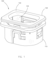
- Apparatus 100 for retaining a plug in a receptacle in accordance with an embodiment of the present disclosure includes a receptacle body 110 and a release device 120.
- Receptacle body 110 includes at least one tab, and the at least one tab may optionally include at least one barb.
- Release device 120 includes a face portion 122 and at least one prong 124.
- Face portion 122 also referred as a front edge, rim, or bezel, may allow a user's fingers to depress the face portion 122 of the release device 120 which causes the at least one prong 124 to come into contact with the at least one tab in order to allow a plug to be removed from the receptacle body 110.
- Receptacle body 110 may include a receptacle, or may surround a receptacle. It is contemplated that receptacle may include a female electrical fitting. Alternately, it is further contemplated that receptacle may include a male electrical fitting, also referred and called an inlet mechanism as shown and further described in FIG. 9 which may connect to a connector as shown in FIG. 10 .
- Receptacle body 110 and release device 120 may be formed of a variety of rigid materials, including plastic, composites and metals. It is contemplated that plastic may be engineering grade and the plastic may be in compliance with local safety requirements.
- the at least one barb of receptacle body 110 may be formed of plastic in one embodiment of the disclosure. In an alternative embodiment, the at least one barb may be formed of metal, such as stainless steel. Additionally, it is contemplated that the barb may be formed of an elastomer material. The elastomer material may form a grip for a friction fit with the shroud of a plug.
- the face portion 122 of the release device 120 may be formed of a hard plastic, such as a nylon plastic
- the elastomer material may be softer and slightly compressible to allow a friction fit with a shroud of a plug.
- the elastomer material may be a thermoplastic elastomer (TPE) material. Additionally, the elastomer material may be acrylonitrile butadiene styrene, polycarbonate, polyethylene, or polypropylene.
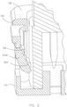
- Receptacle body 110 includes at least one tab 210A, 210B.
- Tab 210A, 210B may be flexible.
- Tab 210A, 210B may include a barb 220.
- Barb 220 may refer to a projection extending from the at least one tab 210A, 210B which is configured to contact a shroud of a plug.
- the insertion of the plug may cause the at least one tab 210A, 210B to extend toward an exterior side of the receptacle body 110 while the at least one tab remains in contact with the plug 250.
- the plug 250 is retained within the receptacle body 110 by pressure applied by the at least one tab 210A, 210B and barb 220, which may be referred as an interference fit or contact fit. While there are two tabs shown, it is contemplated that one, three, or four or more tabs may be employed without departing from the scope and intent of the present disclosure.
- FIG. 3 depicts an exploded cutaway view of an apparatus for retaining a plug in accordance with an embodiment of the present disclosure.
- the release device 120 is configured to be moved toward the interior of the receptacle body 110.
- the one or more prongs 124 of the release device 120 contact the one or more tabs 210A to cause the one or more tabs 210A to extend away from the plug, at which point the plug can be removed from the receptacle body 110. It is contemplated that the one or more prongs 124 may contact the one or more tabs 210A to reduce the pressure applied by the one or more tabs 210A and may or may not remain in slight contact with the plug 250.
- plug 250 may be easily removed from the receptacle body 110. While barb 220 is shown as a jagged edge, it is contemplated that it may be any type of projection, including a flat and substantially straight surface, a curved surface, and the like without departing from the scope or intent of the present disclosure.
- one or more tabs 210A may be retained within an interior portion of the receptacle body.
- Conventional devices to retain plugs may include pins and the like which secure to the plug on the exterior or outside of the receptacle body 110.
- pins and the like which secure to the plug on the exterior or outside of the receptacle body 110.
- such an arrangement reduces the number of receptacles that may be placed in a given area and makes insertion and removal of a plug more difficult as the pins and the like must be accounted for by a user during insertion of the plug and removal of the plug.
- Plug 250 may include a male electrical fitting for making an electrical connection with a corresponding female fitting, such as a receptacle as shown in FIG. 5 . It is contemplated that plug 250 may be electrically coupled with cable 260. Plug 250 may include a shroud 270. In an alternative embodiment, plug 250 may include a female electrical fitting as shown in FIG. 10 for making an electrical connection with a corresponding male fitting, such as an inlet mechanism as shown and described in FIG. 9 . It is contemplated that apparatus for retaining a plug within a receptacle may be functional without any change or modification to the plug 250.
- Apparatus 100 for retaining a plug includes a receptacle body 110.
- Receptacle body 110 includes at least one tab 210A, 210B.
- Tab 210A, 210B may be flexible, and may be formed of metal.
- the insertion of the plug may cause the at least one tab 210A, 210B to extend toward an exterior side of the receptacle body 110 while the at least one tab 210A, 210B remains in contact with the plug. It is contemplated that a plug (not shown in FIG.
- FIG. 5 may be retained within the receptacle body 110 by pressure applied by the at least one tab 210A, 210B to provide an interference fit or contact fit.
- the release device 120 is configured to be moved toward the interior of the receptacle body 110.
- the one or more prongs 124 of the release device 120 contacts the one or more tabs 210A, 210B to cause the one or more tabs 210A, 210B to extend away from the plug, at which point the plug may be removed from the receptacle body 110.
- FIG. 6 depicts another cutaway view of the apparatus for retaining a plug in a receptacle body 110 in accordance with an alternative embodiment of the present disclosure.
- FIG. 7 another cutaway view of the apparatus for retaining a plug in a receptacle body 110 with an inserted plug in accordance with an alternative embodiment of the present disclosure is shown.
- Receptacle body 110 may retain a plug 250 with a shroud 270 by pressure applied by the at least one tab 210A, 210B to provide an interference fit or contact fit.
- the release device 120 is configured to be moved toward the interior of the receptacle body 110.
- the one or more prongs 124 of the release device 120 contact the one or more tabs 210A, 210B to cause the one or more tabs 210A, 210B to extend away from the plug 250, at which point the plug 250 may be removed from the receptacle body 110. It is contemplated that the one or more prongs 124 may contact the one or more tabs 210A to reduce the pressure applied by the one or more tabs 210A, 210B and may or may not remain in slight contact with the plug 250. However, with the reduced pressure applied by the one or more tabs 210A, 210B, plug 250 may be easily removed from the receptacle body 110.
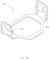
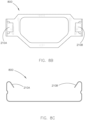
- a tab assembly 800 including two tabs 210A, 210B for placement within a receptacle body in accordance with an embodiment of the present disclosure is shown.
- Tab assembly 800 may include a ring portion with a first tab 210A and a second tab 210B on opposing sides of the tab assembly 800. It is contemplated that tab assembly 800 may be formed of metal. It is further contemplated that tab assembly 800 may be located within a base of receptacle body 110 as shown in FIGS. 5-7 .
- the incorporation of tab assembly 800 with receptacle body 110 may reduce manufacturing costs while maintaining a retention capability. While tab assembly 800 is shown with a first tab 210A and a second tab 210B, it is contemplated that tab assembly 800 may be employed with one, three, or four or more tabs without departing from the scope and intent of the present disclosure.
- Inlet mechanism 910 may be a receptacle that may include a male electrical fitting, including male pins.
- Release device 120 may operate with inlet mechanism 910 to retain a corresponding female electrical fitting, such as connector 940 as shown in FIG. 10 .
- at least one tab (not shown in FIG. 9 ) of the inlet mechanism 910 may contact and retain a shroud of connector 940 whereby the inlet mechanism 910 may operate in a similar fashion as receptacle body 110 to retain a plug 250 within the receptacle body 110 as shown and described in FIGS. 1-3 and 5-7 .
- Power strip 1100 including an apparatus for retaining a plug in a receptacle in accordance with an embodiment of the present disclosure is shown.
- Power strip 1100 may include a plurality of receptacles which supply power to a plurality of electronic devices. It is contemplated that multiple apparatuses 100 for retaining a plug may be employed in a power strip 1100 to prevent unintended disconnection of a plug from a receptacle.
- FIG. 11 also shows a user may press the release device 120 and cause the release device 120 to be moved toward the interior of the receptacle body 110 whereby the one or more tabs of the receptacle body 110 extend away from a plug to allow removal of a plug.
- a power strip 1200 may include an apparatus 100 for retaining a plug in a receptacle and an apparatus 900 for retaining a connector in an inlet mechanism in accordance with an embodiment of the present disclosure is shown. It is contemplated that multiple apparatuses 100, 900 may be employed in a power strip 1200 to prevent unintended disconnection of a plug or connector. It is contemplated that face portion of release device 120 may include one or more protrusions. One or more protrusions may extend from the face portion and may allow easier finger access to the release device to allow removal of a plug.
- apparatus 100, 900 may provide many advantages over locking receptacles known to the conventional art.
- Conventional locking receptacles may include specialized receptacles or specialized plugs.
- Specialized receptacles and specialized plugs create additional costs and reduce the flexibility to change power cords in a large scale electrical power distribution system, such as power strips employed in a data center providing power to multiple data servers.
- apparatus 100, 900 may be operable with power cords supplied by the manufacturers of electronic equipment, such as data servers.
- apparatus 100, 900 may be operable with IEC 60320 couplers, referring to a list of standards from the International Electrotechnical Commission specifying non-locking appliance couplers and interconnection couplers for the connection of power supply cords to electrical appliances up to 250 Volts, including C13, C15, C19 and C21 receptacles. Additionally, it is contemplated that apparatus 100 may be operable with any type of plug that includes a shroud that may cover at least a portion of the pins of the plug. Also, the apparatus 900 may be operable with a female coupler with any type of shroud.
- apparatus 100, 900 may be more effective than conventional devices for retaining plugs. There are required manufacturing tolerances which must be passed in order to comply with the International Electrotechnical Commission standards for specifying non-locking appliance couplers and interconnection couplers for the connection of power supply cords to electrical appliances up to 250 Volts, including C13, C15, C19 and C21 receptacles. As the apparatus 100, 900 is configured to contact sides of a shroud of a plug, and dimensions of the shroud must be within manufacturing compliance, apparatus 100, 900 operates with an increased level of performance than conventional devices for retaining plugs.
- An additional advantage of the apparatus 100, 900 may include the ability to employ labels and different colors. By adding an identifier such as color or a label to the face portion 122 of the release device 120, particular receptacles may be more easily identified and separated, particularly when implemented with a power strip 1100, 1200 as depicted in FIG. 11 and FIG. 12 .
Landscapes
- Details Of Connecting Devices For Male And Female Coupling (AREA)
Description
- The present application claims the benefit under 35 U.S.C. § 119 of
U.S. Provisional Patent Application Serial No. 62/397,208 filed September 20, 2016 - The present disclosure generally relates to the field of computing cables and power cables, and more particularly to an apparatus for retaining a plug within a receptacle.
- Many electronic devices, particularly computer and data storage equipment, are supplied power from an alternating current (AC) power source. A typical power cord may include a cable, the cable including a first plug to connect to the AC power source and a second plug to connect to a receptacle of the electronic device. It is critical for the operation of the electronic device that it receive power to remain operational, particularly for data storage equipment. A problem with many electronic devices is the inadvertent disconnection of the plug of the power cord from the receptacle of the electronic device.
US 2008/207040 A1 relates to an electrical plug connection comprising two plug sections which contain mutually complementary coupling sections. The first plug section comprises a receiving sleeve encircling the first coupling section.US 6142812 A relates to a connector capably of fastening a plug and a jack easily and strengthening the fastening force between the plug and the jack.US 2003/207606 A1 discloses an apparatus according to the preamble of claim 1. - According to an aspect of the present invention, there is provided an apparatus for retaining a plug within a receptacle as defined in claim 1. Accordingly, the present disclosure is directed to an apparatus for retaining a plug within a receptacle. The apparatus for retaining a plug within a receptacle includes a receptacle body and a release device. The receptacle body includes at least one tab, and the at least one tab may include at least one barb. The at least one tab, optionally including the at least one barb, is located within an interior of the receptacle body. When a plug is inserted into the receptacle body, the plug may cause the at least one tab to extend toward an exterior side of the receptacle body while the at least one tab remains in contact with the plug. The plug is retained within the receptacle body with the pressure applied by the at least one tab to the plug. In order to release the plug, a prong of the release device is caused to come into contact with the at least one tab, causing the at least one tab to extend away from the plug, and allowing the plug to be released from the receptacle body.
- It is to be understood that both the foregoing general description and the following detailed description are exemplary and explanatory only and are not necessarily restrictive of the present disclosure. The accompanying drawings, which are incorporated in and constitute a part of the specification, illustrate subject matter of the disclosure. Together, the descriptions and the drawings serve to explain the principles of the disclosure.
- The numerous advantages of the disclosure may be better understood by those skilled in the art by reference to the accompanying figures in which:
-
FIG. 1 depicts an apparatus for retaining a plug in a receptacle in accordance with an embodiment of the present disclosure; -
FIG. 2 depicts a cutaway view of an apparatus for retaining a plug in a receptacle in accordance with an embodiment of the present disclosure; -
FIG. 3 depicts an exploded cutaway view of an apparatus for retaining a plug in accordance with an embodiment of the present disclosure; -
FIG. 4 depicts an exemplary plug which is retained in the apparatus for retaining a plug in accordance with an embodiment of the present disclosure; -
FIG. 5 depicts a cutaway view of the apparatus for retaining a plug in a receptacle in accordance with an alternative embodiment of the present disclosure; -
FIG. 6 depicts another cutaway view of the apparatus for retaining a plug in a receptacle in in accordance with an alternative embodiment of the present disclosure; -
FIG. 7 depicts another cutaway view of the apparatus for retaining a plug in a receptacle with an inserted plug in accordance with an alternative embodiment of the present disclosure; -
FIGS. 8A ,8B, and 8C depict a tab assembly including two tabs for placement within a receptacle body in accordance with an embodiment of the present disclosure; -
FIG. 9 depicts an apparatus for retaining a connector in an inlet mechanism in accordance with an embodiment of the present disclosure; -
FIG. 10 depicts an exemplary connector which is retained in a retaining apparatus in accordance with an embodiment of the present disclosure; -
FIG. 11 depicts a power strip including an apparatus for retaining a plug in a receptacle in accordance with an embodiment of the present disclosure; and -
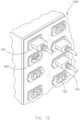
FIG. 12 depicts a power strip including an apparatus for retaining a plug in a receptacle and an apparatus for retaining a connector in an inlet mechanism in accordance with an embodiment of the present disclosure. - Reference will now be made in detail to the subject matter disclosed, which is illustrated in the accompanying drawings.
- Before any embodiments of the disclosure are explained in detail, it is to be understood that the embodiments may not be limited in application per the details of the structure or the function as set forth in the following descriptions or illustrated in the figures. Different embodiments may be capable of being practiced or carried out in various ways. Also, it is to be understood that the phraseology and terminology used herein is for description and should not be regarded as limiting. The use of terms such as "including," "comprising," or "having" and variations thereof herein are generally meant to encompass the item listed thereafter and equivalents thereof as well as additional items. Further, unless otherwise noted, technical terms may be used according to conventional usage. It is further contemplated that like reference numbers may describe similar components and the equivalents thereof.
- Referring to
FIGS. 1-12 , an apparatus for retaining a plug within a receptacle according to various embodiments is shown. The apparatus for retaining a plug within a receptacle the present disclosure is directed to an apparatus for retaining a plug within a receptacle. The apparatus for retaining a plug within a receptacle may include a receptacle body and a release device. In one embodiment, the receptacle body includes at least one tab, and the at least one tab may include at least one barb. The at least one tab, including the at least one barb is located within an interior of the receptacle body. When a plug is inserted into the receptacle body, the plug may cause the at least one tab to extend toward an exterior side of the receptacle body while the at least one tab remains in contact with the plug. The plug is retained within the receptacle body with the pressure applied by the at least one tab to the plug. In order to release the plug, the release device comes into contact with the at least one tab, cause the at least one tab to extend away from the plug, and allow the plug to be released from the receptacle body. - Referring specifically to
FIG. 1 , anapparatus 100 for retaining a plug in a receptacle in accordance with an embodiment of the present disclosure is shown.Apparatus 100 for retaining a plug within a receptacle includes areceptacle body 110 and arelease device 120.Receptacle body 110 includes at least one tab, and the at least one tab may optionally include at least one barb.Release device 120 includes aface portion 122 and at least oneprong 124.Face portion 122, also referred as a front edge, rim, or bezel, may allow a user's fingers to depress theface portion 122 of therelease device 120 which causes the at least oneprong 124 to come into contact with the at least one tab in order to allow a plug to be removed from thereceptacle body 110. -
Receptacle body 110 may include a receptacle, or may surround a receptacle. It is contemplated that receptacle may include a female electrical fitting. Alternately, it is further contemplated that receptacle may include a male electrical fitting, also referred and called an inlet mechanism as shown and further described inFIG. 9 which may connect to a connector as shown inFIG. 10 . -
Receptacle body 110 andrelease device 120 may be formed of a variety of rigid materials, including plastic, composites and metals. It is contemplated that plastic may be engineering grade and the plastic may be in compliance with local safety requirements. The at least one barb ofreceptacle body 110 may be formed of plastic in one embodiment of the disclosure. In an alternative embodiment, the at least one barb may be formed of metal, such as stainless steel. Additionally, it is contemplated that the barb may be formed of an elastomer material. The elastomer material may form a grip for a friction fit with the shroud of a plug. While theface portion 122 of therelease device 120 may be formed of a hard plastic, such as a nylon plastic, the elastomer material may be softer and slightly compressible to allow a friction fit with a shroud of a plug. The elastomer material may be a thermoplastic elastomer (TPE) material. Additionally, the elastomer material may be acrylonitrile butadiene styrene, polycarbonate, polyethylene, or polypropylene. - Referring to
FIG. 2 , a cutaway view of anapparatus 100 for retaining a plug in a receptacle in accordance with an embodiment of the present disclosure is shown.Receptacle body 110 includes at least onetab Tab Tab barb 220.Barb 220 may refer to a projection extending from the at least onetab plug 250 is inserted into thereceptacle body 110, the insertion of the plug may cause the at least onetab receptacle body 110 while the at least one tab remains in contact with theplug 250. Theplug 250 is retained within thereceptacle body 110 by pressure applied by the at least onetab barb 220, which may be referred as an interference fit or contact fit. While there are two tabs shown, it is contemplated that one, three, or four or more tabs may be employed without departing from the scope and intent of the present disclosure. -
FIG. 3 depicts an exploded cutaway view of an apparatus for retaining a plug in accordance with an embodiment of the present disclosure. To release a plug inserted within thereceptacle body 110, therelease device 120 is configured to be moved toward the interior of thereceptacle body 110. The one ormore prongs 124 of therelease device 120 contact the one ormore tabs 210A to cause the one ormore tabs 210A to extend away from the plug, at which point the plug can be removed from thereceptacle body 110. It is contemplated that the one ormore prongs 124 may contact the one ormore tabs 210A to reduce the pressure applied by the one ormore tabs 210A and may or may not remain in slight contact with theplug 250. However, with the reduced pressure applied by the one ormore tabs 210A, plug 250 may be easily removed from thereceptacle body 110. Whilebarb 220 is shown as a jagged edge, it is contemplated that it may be any type of projection, including a flat and substantially straight surface, a curved surface, and the like without departing from the scope or intent of the present disclosure. - In an advantageous aspect of the present disclosure, one or
more tabs 210A may be retained within an interior portion of the receptacle body. Conventional devices to retain plugs may include pins and the like which secure to the plug on the exterior or outside of thereceptacle body 110. However, such an arrangement reduces the number of receptacles that may be placed in a given area and makes insertion and removal of a plug more difficult as the pins and the like must be accounted for by a user during insertion of the plug and removal of the plug. - Referring to
FIG. 4 , anexemplary plug 250 which is retained in the retaining apparatus in accordance with an embodiment of the present disclosure is shown. Plug 250 may include a male electrical fitting for making an electrical connection with a corresponding female fitting, such as a receptacle as shown inFIG. 5 . It is contemplated thatplug 250 may be electrically coupled withcable 260. Plug 250 may include ashroud 270. In an alternative embodiment, plug 250 may include a female electrical fitting as shown inFIG. 10 for making an electrical connection with a corresponding male fitting, such as an inlet mechanism as shown and described inFIG. 9 . It is contemplated that apparatus for retaining a plug within a receptacle may be functional without any change or modification to theplug 250. - Referring to
FIG. 5 , a cutaway view of the apparatus for retaining a plug in a receptacle in accordance with an alternative embodiment of the present disclosure is shown.Apparatus 100 for retaining a plug includes areceptacle body 110.Receptacle body 110 includes at least onetab Tab receptacle body 110, the insertion of the plug may cause the at least onetab receptacle body 110 while the at least onetab FIG. 5 ) may be retained within thereceptacle body 110 by pressure applied by the at least onetab receptacle body 110, therelease device 120 is configured to be moved toward the interior of thereceptacle body 110. The one ormore prongs 124 of therelease device 120 contacts the one ormore tabs more tabs receptacle body 110.FIG. 6 depicts another cutaway view of the apparatus for retaining a plug in areceptacle body 110 in accordance with an alternative embodiment of the present disclosure. - Referring to
FIG. 7 , another cutaway view of the apparatus for retaining a plug in areceptacle body 110 with an inserted plug in accordance with an alternative embodiment of the present disclosure is shown.Receptacle body 110 may retain aplug 250 with ashroud 270 by pressure applied by the at least onetab plug 250 inserted within thereceptacle body 110, therelease device 120 is configured to be moved toward the interior of thereceptacle body 110. The one ormore prongs 124 of therelease device 120 contact the one ormore tabs more tabs plug 250, at which point theplug 250 may be removed from thereceptacle body 110. It is contemplated that the one ormore prongs 124 may contact the one ormore tabs 210A to reduce the pressure applied by the one ormore tabs plug 250. However, with the reduced pressure applied by the one ormore tabs receptacle body 110. - Referring to
FIGS. 8A ,8B, and 8C , atab assembly 800 including twotabs Tab assembly 800 may include a ring portion with afirst tab 210A and asecond tab 210B on opposing sides of thetab assembly 800. It is contemplated thattab assembly 800 may be formed of metal. It is further contemplated thattab assembly 800 may be located within a base ofreceptacle body 110 as shown inFIGS. 5-7 . Advantageously, the incorporation oftab assembly 800 withreceptacle body 110 may reduce manufacturing costs while maintaining a retention capability. Whiletab assembly 800 is shown with afirst tab 210A and asecond tab 210B, it is contemplated thattab assembly 800 may be employed with one, three, or four or more tabs without departing from the scope and intent of the present disclosure. - Referring to
FIG. 9 and FIG. 10 , anapparatus 900 for retaining aconnector 940 in aninlet mechanism 910 in accordance with an embodiment of the present disclosure is shown.Inlet mechanism 910 may be a receptacle that may include a male electrical fitting, including male pins.Release device 120 may operate withinlet mechanism 910 to retain a corresponding female electrical fitting, such asconnector 940 as shown inFIG. 10 . It is contemplated that at least one tab (not shown inFIG. 9 ) of theinlet mechanism 910 may contact and retain a shroud ofconnector 940 whereby theinlet mechanism 910 may operate in a similar fashion asreceptacle body 110 to retain aplug 250 within thereceptacle body 110 as shown and described inFIGS. 1-3 and5-7 . - Referring to
FIG. 11 , apower strip 1100 including an apparatus for retaining a plug in a receptacle in accordance with an embodiment of the present disclosure is shown.Power strip 1100 may include a plurality of receptacles which supply power to a plurality of electronic devices. It is contemplated thatmultiple apparatuses 100 for retaining a plug may be employed in apower strip 1100 to prevent unintended disconnection of a plug from a receptacle.FIG. 11 also shows a user may press therelease device 120 and cause therelease device 120 to be moved toward the interior of thereceptacle body 110 whereby the one or more tabs of thereceptacle body 110 extend away from a plug to allow removal of a plug. - Referring to
FIG. 12 , apower strip 1200 may include anapparatus 100 for retaining a plug in a receptacle and anapparatus 900 for retaining a connector in an inlet mechanism in accordance with an embodiment of the present disclosure is shown. It is contemplated thatmultiple apparatuses power strip 1200 to prevent unintended disconnection of a plug or connector. It is contemplated that face portion ofrelease device 120 may include one or more protrusions. One or more protrusions may extend from the face portion and may allow easier finger access to the release device to allow removal of a plug. - It is contemplated that
apparatus apparatus - It is contemplated that
apparatus apparatus 100 may be operable with any type of plug that includes a shroud that may cover at least a portion of the pins of the plug. Also, theapparatus 900 may be operable with a female coupler with any type of shroud. - It is contemplated that
apparatus apparatus apparatus - An additional advantage of the
apparatus face portion 122 of therelease device 120, particular receptacles may be more easily identified and separated, particularly when implemented with apower strip FIG. 11 andFIG. 12 . - It is believed that the present disclosure and many of its attendant advantages will be understood by the foregoing description, and it will be apparent that various changes may be made in the form, construction and arrangement of the components without departing from the disclosed subject matter or without sacrificing all of its material advantages. The form described is merely explanatory, and the invention is defined by the following claims .
Claims (13)
- An apparatus (100) for retaining a plug within a receptacle, comprising:a receptacle body (110), the receptacle body including at least one tab (210A, 210B) configured to make contact with a plug when the plug is inserted within the receptacle body, the at least one tab is located within an interior of the receptacle body; anda release device (120) disposed within the receptacle body, the release device including a face portion (122) and at least one prong (124), wherein the release device is configured to allow the face portion to be depressed and cause the at least one prong to come into contact with the at least one tab and extend the at least one tab away from the plug in order to allow the plug to be removed from the receptacle body, characterised in that the at least one tab is further configured to retain the plug within the receptacle when the plug is inserted therein by applying pressure to the plug to provide an interference fit.
- The apparatus as claimed in claim 1, wherein the at least one tab (210A, 210B) is part of a tab assembly (800), the tab assembly including a ring located in a base of the receptacle body with a first tab (210A) and a second tab (210B) on opposing sides of the tab assembly.
- The apparatus as claimed in claim 2, wherein:the first tab (210A) and the second tab (210B) are configured to make contact with a plug (250) when the plug is inserted within the receptacle body (110), the first tab and the second tab are located within an interior of the receptacle body; andthe release device (120) is configured to contact the first tab and the second tab and extend the first tab and the second tab away from the plug to allow the plug to be released from the receptacle body.
- The apparatus as claimed in claim 3, wherein the tab assembly (800) is formed of metal.
- The apparatus as claimed in claims 1-4, wherein the receptacle body (110) includes a receptacle.
- The apparatus as claimed in claim 5, wherein said receptacle includes a female electrical fitting.
- The apparatus as claimed in claim 6, wherein said plug (250) includes a male electrical fitting.
- The apparatus as claimed in claim 5, wherein said receptacle includes a male electrical fitting.
- The apparatus as claimed in claim 8, wherein said plug (250) includes a female electrical fitting.
- The apparatus as claimed in claim 1, wherein the at least one tab (210A, 210B) is formed of plastic.
- The apparatus as claimed in claim 10, wherein the at least one tab includes at least one barb (220).
- The apparatus as claimed in claim 1, wherein the at least one tab (210A, 210B) is formed of metal.
- The apparatus as claimed in claim 4, wherein the release device (120) includes at least two prongs (124) configured to depress the first tab (210A) and the second tab (210B) of the tab assembly (800).
Applications Claiming Priority (2)
| Application Number | Priority Date | Filing Date | Title |
|---|---|---|---|
| US201662397208P | 2016-09-20 | 2016-09-20 | |
| PCT/US2017/052553 WO2018057646A1 (en) | 2016-09-20 | 2017-09-20 | Apparatus for retaining a plug in a receptacle |
Publications (3)
| Publication Number | Publication Date |
|---|---|
| EP3516742A1 EP3516742A1 (en) | 2019-07-31 |
| EP3516742A4 EP3516742A4 (en) | 2020-05-27 |
| EP3516742B1 true EP3516742B1 (en) | 2025-03-26 |
Family
ID=61620681
Family Applications (1)
| Application Number | Title | Priority Date | Filing Date |
|---|---|---|---|
| EP17853827.8A Active EP3516742B1 (en) | 2016-09-20 | 2017-09-20 | Apparatus for retaining a plug in a receptacle |
Country Status (8)
| Country | Link |
|---|---|
| US (1) | US10205281B2 (en) |
| EP (1) | EP3516742B1 (en) |
| CN (1) | CN109792119B (en) |
| DK (1) | DK3516742T3 (en) |
| ES (1) | ES3023039T3 (en) |
| FI (1) | FI3516742T3 (en) |
| PL (1) | PL3516742T3 (en) |
| WO (1) | WO2018057646A1 (en) |
Families Citing this family (13)
| Publication number | Priority date | Publication date | Assignee | Title |
|---|---|---|---|---|
| US8587950B2 (en) | 2011-05-31 | 2013-11-19 | Server Technology, Inc. | Method and apparatus for multiple input power distribution to adjacent outputs |
| US10249998B2 (en) | 2017-07-13 | 2019-04-02 | Server Technology, Inc. | Combination outlet and power distribution unit incorporating the same |
| CA3077721C (en) * | 2017-11-02 | 2024-01-23 | Vertiv Corporation | Apparatus for providing power for multiple types of plugs via a single receptacle |
| US11721939B2 (en) * | 2018-04-06 | 2023-08-08 | Drägerwerk AG & Co. KGaA | Modular patient monitoring medical device and connector |
| US11936137B2 (en) | 2018-12-28 | 2024-03-19 | Drägerwerk AG & Co. KGaA | Systems, monitor mounts, monitors, docks, racks, modules, belt mounts, couplings and connectors |
| US11196212B2 (en) | 2020-03-16 | 2021-12-07 | Server Technology, Inc. | Locking combination outlet module and power distribution unit incorporating the same |
| USD971709S1 (en) * | 2020-09-28 | 2022-12-06 | Powertek Limited | Combined lock |
| US11276970B1 (en) | 2020-10-14 | 2022-03-15 | Cis Global Llc | Combination outlet assembly and power distribution unit including the same |
| CN114628947B (en) * | 2020-12-11 | 2024-04-19 | 苏州佳世达光电有限公司 | Plug fixing structure and electronic device with plug anti-pulling function |
| WO2022144380A1 (en) | 2020-12-30 | 2022-07-07 | Drägerwerk AG & Co. KGaA | Mounting and locking mechanisms for a patient monitoring system |
| USD1027860S1 (en) * | 2021-07-06 | 2024-05-21 | Bizlink Electronic (Xiamen) Co., Ltd | Power connector |
| US12537352B2 (en) * | 2022-09-30 | 2026-01-27 | Panduit Corp. | Combination outlet |
| USD1103747S1 (en) | 2023-10-16 | 2025-12-02 | Baxter International Inc. | Cable retainer |
Citations (2)
| Publication number | Priority date | Publication date | Assignee | Title |
|---|---|---|---|---|
| US7695302B2 (en) * | 2003-03-31 | 2010-04-13 | Woodhead Industries, Inc. | Electrical connector |
| US8968021B1 (en) * | 2013-12-11 | 2015-03-03 | JAE Oregon, Inc. | Self-rejecting automotive harness connector |
Family Cites Families (39)
| Publication number | Priority date | Publication date | Assignee | Title |
|---|---|---|---|---|
| US4618200A (en) | 1985-02-22 | 1986-10-21 | David Roberts | Electrical plug restraint system |
| US4917625A (en) * | 1988-07-25 | 1990-04-17 | Ernest Haile | Snap-on electrical connector for electrical cord having mating plugs |
| IT1243882B (en) | 1990-10-31 | 1994-06-28 | C M S R L | DEVICE FOR CONNECTION OF A PLUG TO A SOCKET OF COAXIAL CONNECTORS |
| US5921799A (en) * | 1997-08-14 | 1999-07-13 | Forrester; David | Electrical receptacle with releasable locking mechanism |
| JP3570478B2 (en) * | 1998-02-16 | 2004-09-29 | 住友電装株式会社 | connector |
| KR200246718Y1 (en) * | 1998-06-02 | 2001-12-17 | 김덕용 | Connector fastening device |
| GB0019449D0 (en) | 2000-08-09 | 2000-09-27 | Connell Michelle C O | Electric socket/plug cover |
| US6520792B2 (en) * | 2000-12-04 | 2003-02-18 | Delta Electronics, Inc. | Adjustable securing device |
| US20030207606A1 (en) * | 2001-02-22 | 2003-11-06 | Ho Su Yueh | Locking and releasable electrical receptacle/connector |
| US6443762B1 (en) * | 2001-06-04 | 2002-09-03 | Black & Decker Inc. | Power tool cord retainer |
| JP3806926B2 (en) * | 2002-03-01 | 2006-08-09 | 住友電装株式会社 | connector |
| GB2399461A (en) * | 2003-03-11 | 2004-09-15 | Sandal Plc | A lockable electrical adapter |
| US6769930B1 (en) | 2003-06-04 | 2004-08-03 | Mcdevitt, Jr. Charles J. | Child proof outlet/adapter apparatus |
| US7014493B1 (en) | 2003-07-10 | 2006-03-21 | Battard Derek J | Retaining socket for electrical outlets |
| US6939161B1 (en) | 2003-11-12 | 2005-09-06 | Cisco Technology, Inc. | Methods and apparatus for securing a cable connector to a device |
| US7101215B2 (en) | 2004-03-31 | 2006-09-05 | Hewlett-Packard Development Company, L.P. | Cable plug retention clip |
| JP4479474B2 (en) * | 2004-11-12 | 2010-06-09 | 住友電装株式会社 | connector |
| JP4437982B2 (en) | 2005-08-08 | 2010-03-24 | ヒロセ電機株式会社 | Electrical connector for flat cable |
| SG137710A1 (en) * | 2006-05-11 | 2007-12-28 | Volex Asia Pte Ltd | Positive lock connector |
| US7559788B2 (en) | 2007-06-04 | 2009-07-14 | The Nielsen Company (Us), Llc | Connector retainers and methods of securing a connector in a receptacle |
| GB2463468C (en) | 2008-09-11 | 2016-07-27 | Burland Technology Solutions Ltd | Locking power connector apparatus |
| US7722380B1 (en) | 2009-03-27 | 2010-05-25 | Panduit Corp. | Plug retention device |
| US8038454B2 (en) | 2010-03-09 | 2011-10-18 | American Power Conversion Corporation | Back-mount ganged electrical outlets |
| US8109778B2 (en) * | 2010-04-08 | 2012-02-07 | Jeff Joseph Howard | Electrical connector lock |
| US8469734B2 (en) | 2010-04-20 | 2013-06-25 | Liang Light Chen | Retainer system for electric cable couplers |
| US20120015541A1 (en) | 2010-07-15 | 2012-01-19 | Juniper Networks, Inc. | Self-securing power cord |
| EP2754210B1 (en) | 2011-09-08 | 2018-10-24 | Zonit Structured Solutions | Secure electrical receptacle |
| TWM423387U (en) * | 2011-09-30 | 2012-02-21 | Chun Nien Plastic Led | Safety socket |
| TWM428560U (en) * | 2011-12-06 | 2012-05-01 | Chun Nien Plastic Led | Locking socket |
| TWM430748U (en) * | 2011-12-14 | 2012-06-01 | Chun Nien Plastic Led | Switching safety socket |
| US8956177B2 (en) | 2011-12-16 | 2015-02-17 | Shawn L. Warner | Electrical cord/outlet safety lock and method |
| TWM450107U (en) * | 2012-03-16 | 2013-04-01 | Chun Nien Plastic Led | Safe socket |
| EP2639895A1 (en) * | 2012-03-16 | 2013-09-18 | EATON Industries Manufacturing GmbH | Electrical plug retainer outlet |
| TWM458002U (en) * | 2013-02-08 | 2013-07-21 | Chun Nien Plastic Led | Safe socket |
| WO2015038945A1 (en) * | 2013-09-12 | 2015-03-19 | Pce, Inc. | Apparatus for retaining plug in a receptacle |
| WO2016144285A2 (en) * | 2013-12-13 | 2016-09-15 | Hewlett Packard Enterprise Development Lp | Connector with a retainer assembly |
| TWM489385U (en) * | 2014-03-28 | 2014-11-01 | Rong Feng Industrial Co Ltd | Plug-socket set inverted hook improvement device |
| JP2017520887A (en) * | 2014-06-05 | 2017-07-27 | チャッツワース プロダクツ、インク. | Electrical outlet with locking mechanism |
| FR3029703B1 (en) * | 2014-12-09 | 2017-12-15 | Legrand France | ELECTRICAL SOCKET DEVICE COMPRISING AT LEAST ONE LOCKING AND UNLOCKING ELEMENT |
-
2017
- 2017-09-20 ES ES17853827T patent/ES3023039T3/en active Active
- 2017-09-20 WO PCT/US2017/052553 patent/WO2018057646A1/en not_active Ceased
- 2017-09-20 FI FIEP17853827.8T patent/FI3516742T3/en active
- 2017-09-20 EP EP17853827.8A patent/EP3516742B1/en active Active
- 2017-09-20 PL PL17853827.8T patent/PL3516742T3/en unknown
- 2017-09-20 US US15/710,409 patent/US10205281B2/en active Active
- 2017-09-20 DK DK17853827.8T patent/DK3516742T3/en active
- 2017-09-20 CN CN201780054197.9A patent/CN109792119B/en active Active
Patent Citations (2)
| Publication number | Priority date | Publication date | Assignee | Title |
|---|---|---|---|---|
| US7695302B2 (en) * | 2003-03-31 | 2010-04-13 | Woodhead Industries, Inc. | Electrical connector |
| US8968021B1 (en) * | 2013-12-11 | 2015-03-03 | JAE Oregon, Inc. | Self-rejecting automotive harness connector |
Also Published As
| Publication number | Publication date |
|---|---|
| WO2018057646A1 (en) | 2018-03-29 |
| EP3516742A4 (en) | 2020-05-27 |
| DK3516742T3 (en) | 2025-04-28 |
| FI3516742T3 (en) | 2025-06-03 |
| PL3516742T3 (en) | 2025-07-28 |
| CA3035249A1 (en) | 2018-03-29 |
| US20180083387A1 (en) | 2018-03-22 |
| CN109792119B (en) | 2022-01-25 |
| EP3516742A1 (en) | 2019-07-31 |
| US10205281B2 (en) | 2019-02-12 |
| CN109792119A (en) | 2019-05-21 |
| ES3023039T3 (en) | 2025-05-29 |
Similar Documents
| Publication | Publication Date | Title |
|---|---|---|
| US10205281B2 (en) | Apparatus for retaining a plug within a receptacle | |
| US9276357B2 (en) | Apparatus for retaining a plug in a receptacle | |
| CA3077721C (en) | Apparatus for providing power for multiple types of plugs via a single receptacle | |
| EP2381541B1 (en) | Retainer system | |
| US9692178B2 (en) | Apparatus for retaining a plug in a receptacle | |
| US9531126B2 (en) | Electrical receptacle with locking feature | |
| AU2018264563B2 (en) | A device and a method for locking electrical plugs to power outlets | |
| EP2639895A1 (en) | Electrical plug retainer outlet | |
| US4307924A (en) | Electrical plug having integral finger pull and cord grip | |
| US9425531B2 (en) | Stage pin connector | |
| CA3035249C (en) | Apparatus for retaining a plug in a receptacle | |
| US11552429B2 (en) | Power plug retention clip | |
| KR101567654B1 (en) | Power plug | |
| EP3044839B1 (en) | Apparatus for retaining plug in a receptacle | |
| CN211556320U (en) | Single pin power connector | |
| TWM480797U (en) | Network connector plug |
Legal Events
| Date | Code | Title | Description |
|---|---|---|---|
| STAA | Information on the status of an ep patent application or granted ep patent |
Free format text: STATUS: THE INTERNATIONAL PUBLICATION HAS BEEN MADE |
|
| PUAI | Public reference made under article 153(3) epc to a published international application that has entered the european phase |
Free format text: ORIGINAL CODE: 0009012 |
|
| STAA | Information on the status of an ep patent application or granted ep patent |
Free format text: STATUS: REQUEST FOR EXAMINATION WAS MADE |
|
| 17P | Request for examination filed |
Effective date: 20190319 |
|
| AK | Designated contracting states |
Kind code of ref document: A1 Designated state(s): AL AT BE BG CH CY CZ DE DK EE ES FI FR GB GR HR HU IE IS IT LI LT LU LV MC MK MT NL NO PL PT RO RS SE SI SK SM TR |
|
| AX | Request for extension of the european patent |
Extension state: BA ME |
|
| DAV | Request for validation of the european patent (deleted) | ||
| DAX | Request for extension of the european patent (deleted) | ||
| A4 | Supplementary search report drawn up and despatched |
Effective date: 20200430 |
|
| RIC1 | Information provided on ipc code assigned before grant |
Ipc: H01R 13/639 20060101ALI20200423BHEP Ipc: H01R 13/627 20060101AFI20200423BHEP Ipc: H01R 24/78 20110101ALN20200423BHEP Ipc: H01R 13/635 20060101ALI20200423BHEP |
|
| STAA | Information on the status of an ep patent application or granted ep patent |
Free format text: STATUS: EXAMINATION IS IN PROGRESS |
|
| 17Q | First examination report despatched |
Effective date: 20210930 |
|
| REG | Reference to a national code |
Ref legal event code: R079 Free format text: PREVIOUS MAIN CLASS: H01R0013620000 Ref country code: DE Ref legal event code: R079 Ref document number: 602017088576 Country of ref document: DE Free format text: PREVIOUS MAIN CLASS: H01R0013620000 Ipc: H01R0013627000 |
|
| GRAP | Despatch of communication of intention to grant a patent |
Free format text: ORIGINAL CODE: EPIDOSNIGR1 |
|
| STAA | Information on the status of an ep patent application or granted ep patent |
Free format text: STATUS: GRANT OF PATENT IS INTENDED |
|
| RIC1 | Information provided on ipc code assigned before grant |
Ipc: H01R 24/78 20110101ALN20241002BHEP Ipc: H01R 13/639 20060101ALI20241002BHEP Ipc: H01R 13/635 20060101ALI20241002BHEP Ipc: H01R 13/627 20060101AFI20241002BHEP |
|
| INTG | Intention to grant announced |
Effective date: 20241018 |
|
| GRAS | Grant fee paid |
Free format text: ORIGINAL CODE: EPIDOSNIGR3 |
|
| GRAA | (expected) grant |
Free format text: ORIGINAL CODE: 0009210 |
|
| STAA | Information on the status of an ep patent application or granted ep patent |
Free format text: STATUS: THE PATENT HAS BEEN GRANTED |
|
| RAP3 | Party data changed (applicant data changed or rights of an application transferred) |
Owner name: VERTIV CORPORATION |
|
| AK | Designated contracting states |
Kind code of ref document: B1 Designated state(s): AL AT BE BG CH CY CZ DE DK EE ES FI FR GB GR HR HU IE IS IT LI LT LU LV MC MK MT NL NO PL PT RO RS SE SI SK SM TR |
|
| REG | Reference to a national code |
Ref country code: GB Ref legal event code: FG4D |
|
| REG | Reference to a national code |
Ref country code: CH Ref legal event code: EP |
|
| REG | Reference to a national code |
Ref country code: DE Ref legal event code: R096 Ref document number: 602017088576 Country of ref document: DE |
|
| REG | Reference to a national code |
Ref country code: IE Ref legal event code: FG4D |
|
| REG | Reference to a national code |
Ref country code: DK Ref legal event code: T3 Effective date: 20250422 |
|
| REG | Reference to a national code |
Ref country code: SE Ref legal event code: TRGR |
|
| REG | Reference to a national code |
Ref country code: ES Ref legal event code: FG2A Ref document number: 3023039 Country of ref document: ES Kind code of ref document: T3 Effective date: 20250529 |
|
| REG | Reference to a national code |
Ref country code: FI Ref legal event code: FGE |
|
| REG | Reference to a national code |
Ref country code: NL Ref legal event code: FP |
|
| PG25 | Lapsed in a contracting state [announced via postgrant information from national office to epo] |
Ref country code: RS Free format text: LAPSE BECAUSE OF FAILURE TO SUBMIT A TRANSLATION OF THE DESCRIPTION OR TO PAY THE FEE WITHIN THE PRESCRIBED TIME-LIMIT Effective date: 20250626 |
|
| REG | Reference to a national code |
Ref country code: LT Ref legal event code: MG9D |
|
| PG25 | Lapsed in a contracting state [announced via postgrant information from national office to epo] |
Ref country code: HR Free format text: LAPSE BECAUSE OF FAILURE TO SUBMIT A TRANSLATION OF THE DESCRIPTION OR TO PAY THE FEE WITHIN THE PRESCRIBED TIME-LIMIT Effective date: 20250326 |
|
| PG25 | Lapsed in a contracting state [announced via postgrant information from national office to epo] |
Ref country code: LV Free format text: LAPSE BECAUSE OF FAILURE TO SUBMIT A TRANSLATION OF THE DESCRIPTION OR TO PAY THE FEE WITHIN THE PRESCRIBED TIME-LIMIT Effective date: 20250326 |
|
| PG25 | Lapsed in a contracting state [announced via postgrant information from national office to epo] |
Ref country code: GR Free format text: LAPSE BECAUSE OF FAILURE TO SUBMIT A TRANSLATION OF THE DESCRIPTION OR TO PAY THE FEE WITHIN THE PRESCRIBED TIME-LIMIT Effective date: 20250627 Ref country code: BG Free format text: LAPSE BECAUSE OF FAILURE TO SUBMIT A TRANSLATION OF THE DESCRIPTION OR TO PAY THE FEE WITHIN THE PRESCRIBED TIME-LIMIT Effective date: 20250326 |
|
| REG | Reference to a national code |
Ref country code: AT Ref legal event code: MK05 Ref document number: 1779916 Country of ref document: AT Kind code of ref document: T Effective date: 20250326 |
|
| REG | Reference to a national code |
Ref country code: CH Ref legal event code: U11 Free format text: ST27 STATUS EVENT CODE: U-0-0-U10-U11 (AS PROVIDED BY THE NATIONAL OFFICE) Effective date: 20251001 |
|
| PG25 | Lapsed in a contracting state [announced via postgrant information from national office to epo] |
Ref country code: SM Free format text: LAPSE BECAUSE OF FAILURE TO SUBMIT A TRANSLATION OF THE DESCRIPTION OR TO PAY THE FEE WITHIN THE PRESCRIBED TIME-LIMIT Effective date: 20250326 |
|
| PG25 | Lapsed in a contracting state [announced via postgrant information from national office to epo] |
Ref country code: PT Free format text: LAPSE BECAUSE OF FAILURE TO SUBMIT A TRANSLATION OF THE DESCRIPTION OR TO PAY THE FEE WITHIN THE PRESCRIBED TIME-LIMIT Effective date: 20250728 |
|
| PGFP | Annual fee paid to national office [announced via postgrant information from national office to epo] |
Ref country code: FI Payment date: 20250925 Year of fee payment: 9 |
|
| PGFP | Annual fee paid to national office [announced via postgrant information from national office to epo] |
Ref country code: DE Payment date: 20250929 Year of fee payment: 9 Ref country code: DK Payment date: 20250925 Year of fee payment: 9 |
|
| PGFP | Annual fee paid to national office [announced via postgrant information from national office to epo] |
Ref country code: NO Payment date: 20250929 Year of fee payment: 9 |
|
| PGFP | Annual fee paid to national office [announced via postgrant information from national office to epo] |
Ref country code: PL Payment date: 20250905 Year of fee payment: 9 Ref country code: NL Payment date: 20250926 Year of fee payment: 9 Ref country code: IT Payment date: 20250919 Year of fee payment: 9 |
|
| PGFP | Annual fee paid to national office [announced via postgrant information from national office to epo] |
Ref country code: BE Payment date: 20250929 Year of fee payment: 9 Ref country code: GB Payment date: 20250929 Year of fee payment: 9 |
|
| PG25 | Lapsed in a contracting state [announced via postgrant information from national office to epo] |
Ref country code: AT Free format text: LAPSE BECAUSE OF FAILURE TO SUBMIT A TRANSLATION OF THE DESCRIPTION OR TO PAY THE FEE WITHIN THE PRESCRIBED TIME-LIMIT Effective date: 20250326 |
|
| PGFP | Annual fee paid to national office [announced via postgrant information from national office to epo] |
Ref country code: FR Payment date: 20250925 Year of fee payment: 9 |
|
| PGFP | Annual fee paid to national office [announced via postgrant information from national office to epo] |
Ref country code: SE Payment date: 20250927 Year of fee payment: 9 |
|
| PG25 | Lapsed in a contracting state [announced via postgrant information from national office to epo] |
Ref country code: EE Free format text: LAPSE BECAUSE OF FAILURE TO SUBMIT A TRANSLATION OF THE DESCRIPTION OR TO PAY THE FEE WITHIN THE PRESCRIBED TIME-LIMIT Effective date: 20250326 |
|
| PGFP | Annual fee paid to national office [announced via postgrant information from national office to epo] |
Ref country code: CZ Payment date: 20250908 Year of fee payment: 9 Ref country code: IE Payment date: 20250929 Year of fee payment: 9 |
|
| PG25 | Lapsed in a contracting state [announced via postgrant information from national office to epo] |
Ref country code: RO Free format text: LAPSE BECAUSE OF FAILURE TO SUBMIT A TRANSLATION OF THE DESCRIPTION OR TO PAY THE FEE WITHIN THE PRESCRIBED TIME-LIMIT Effective date: 20250326 |
|
| PG25 | Lapsed in a contracting state [announced via postgrant information from national office to epo] |
Ref country code: SK Free format text: LAPSE BECAUSE OF FAILURE TO SUBMIT A TRANSLATION OF THE DESCRIPTION OR TO PAY THE FEE WITHIN THE PRESCRIBED TIME-LIMIT Effective date: 20250326 |
|
| PG25 | Lapsed in a contracting state [announced via postgrant information from national office to epo] |
Ref country code: IS Free format text: LAPSE BECAUSE OF FAILURE TO SUBMIT A TRANSLATION OF THE DESCRIPTION OR TO PAY THE FEE WITHIN THE PRESCRIBED TIME-LIMIT Effective date: 20250726 |
|
| REG | Reference to a national code |
Ref country code: DE Ref legal event code: R097 Ref document number: 602017088576 Country of ref document: DE |
|
| PGFP | Annual fee paid to national office [announced via postgrant information from national office to epo] |
Ref country code: CH Payment date: 20251001 Year of fee payment: 9 |
|
| PGFP | Annual fee paid to national office [announced via postgrant information from national office to epo] |
Ref country code: ES Payment date: 20251001 Year of fee payment: 9 |
|
| PLBE | No opposition filed within time limit |
Free format text: ORIGINAL CODE: 0009261 |
|
| STAA | Information on the status of an ep patent application or granted ep patent |
Free format text: STATUS: NO OPPOSITION FILED WITHIN TIME LIMIT |
|
| REG | Reference to a national code |
Ref country code: CH Ref legal event code: L10 Free format text: ST27 STATUS EVENT CODE: U-0-0-L10-L00 (AS PROVIDED BY THE NATIONAL OFFICE) Effective date: 20260211 |
|
| 26N | No opposition filed |
Effective date: 20260105 |