EP3516415B1 - Adaptive transmission power control for a lidar - Google Patents
Adaptive transmission power control for a lidar Download PDFInfo
- Publication number
- EP3516415B1 EP3516415B1 EP17740850.7A EP17740850A EP3516415B1 EP 3516415 B1 EP3516415 B1 EP 3516415B1 EP 17740850 A EP17740850 A EP 17740850A EP 3516415 B1 EP3516415 B1 EP 3516415B1
- Authority
- EP
- European Patent Office
- Prior art keywords
- pulses
- power
- pulse
- photon
- detectors
- Prior art date
- Legal status (The legal status is an assumption and is not a legal conclusion. Google has not performed a legal analysis and makes no representation as to the accuracy of the status listed.)
- Active
Links
Images


Classifications
-
- G—PHYSICS
- G01—MEASURING; TESTING
- G01B—MEASURING LENGTH, THICKNESS OR SIMILAR LINEAR DIMENSIONS; MEASURING ANGLES; MEASURING AREAS; MEASURING IRREGULARITIES OF SURFACES OR CONTOURS
- G01B11/00—Measuring arrangements characterised by the use of optical techniques
- G01B11/02—Measuring arrangements characterised by the use of optical techniques for measuring length, width or thickness
- G01B11/026—Measuring arrangements characterised by the use of optical techniques for measuring length, width or thickness by measuring distance between sensor and object
-
- G—PHYSICS
- G01—MEASURING; TESTING
- G01S—RADIO DIRECTION-FINDING; RADIO NAVIGATION; DETERMINING DISTANCE OR VELOCITY BY USE OF RADIO WAVES; LOCATING OR PRESENCE-DETECTING BY USE OF THE REFLECTION OR RERADIATION OF RADIO WAVES; ANALOGOUS ARRANGEMENTS USING OTHER WAVES
- G01S17/00—Systems using the reflection or reradiation of electromagnetic waves other than radio waves, e.g. lidar systems
- G01S17/02—Systems using the reflection of electromagnetic waves other than radio waves
- G01S17/06—Systems determining position data of a target
- G01S17/08—Systems determining position data of a target for measuring distance only
- G01S17/10—Systems determining position data of a target for measuring distance only using transmission of interrupted, pulse-modulated waves
-
- G—PHYSICS
- G01—MEASURING; TESTING
- G01S—RADIO DIRECTION-FINDING; RADIO NAVIGATION; DETERMINING DISTANCE OR VELOCITY BY USE OF RADIO WAVES; LOCATING OR PRESENCE-DETECTING BY USE OF THE REFLECTION OR RERADIATION OF RADIO WAVES; ANALOGOUS ARRANGEMENTS USING OTHER WAVES
- G01S7/00—Details of systems according to groups G01S13/00, G01S15/00, G01S17/00
- G01S7/48—Details of systems according to groups G01S13/00, G01S15/00, G01S17/00 of systems according to group G01S17/00
- G01S7/481—Constructional features, e.g. arrangements of optical elements
- G01S7/4814—Constructional features, e.g. arrangements of optical elements of transmitters alone
-
- G—PHYSICS
- G01—MEASURING; TESTING
- G01S—RADIO DIRECTION-FINDING; RADIO NAVIGATION; DETERMINING DISTANCE OR VELOCITY BY USE OF RADIO WAVES; LOCATING OR PRESENCE-DETECTING BY USE OF THE REFLECTION OR RERADIATION OF RADIO WAVES; ANALOGOUS ARRANGEMENTS USING OTHER WAVES
- G01S7/00—Details of systems according to groups G01S13/00, G01S15/00, G01S17/00
- G01S7/48—Details of systems according to groups G01S13/00, G01S15/00, G01S17/00 of systems according to group G01S17/00
- G01S7/481—Constructional features, e.g. arrangements of optical elements
- G01S7/4817—Constructional features, e.g. arrangements of optical elements relating to scanning
-
- G—PHYSICS
- G01—MEASURING; TESTING
- G01S—RADIO DIRECTION-FINDING; RADIO NAVIGATION; DETERMINING DISTANCE OR VELOCITY BY USE OF RADIO WAVES; LOCATING OR PRESENCE-DETECTING BY USE OF THE REFLECTION OR RERADIATION OF RADIO WAVES; ANALOGOUS ARRANGEMENTS USING OTHER WAVES
- G01S7/00—Details of systems according to groups G01S13/00, G01S15/00, G01S17/00
- G01S7/48—Details of systems according to groups G01S13/00, G01S15/00, G01S17/00 of systems according to group G01S17/00
- G01S7/483—Details of pulse systems
- G01S7/484—Transmitters
-
- G—PHYSICS
- G01—MEASURING; TESTING
- G01S—RADIO DIRECTION-FINDING; RADIO NAVIGATION; DETERMINING DISTANCE OR VELOCITY BY USE OF RADIO WAVES; LOCATING OR PRESENCE-DETECTING BY USE OF THE REFLECTION OR RERADIATION OF RADIO WAVES; ANALOGOUS ARRANGEMENTS USING OTHER WAVES
- G01S7/00—Details of systems according to groups G01S13/00, G01S15/00, G01S17/00
- G01S7/48—Details of systems according to groups G01S13/00, G01S15/00, G01S17/00 of systems according to group G01S17/00
- G01S7/483—Details of pulse systems
- G01S7/486—Receivers
- G01S7/4861—Circuits for detection, sampling, integration or read-out
- G01S7/4863—Detector arrays, e.g. charge-transfer gates
-
- G—PHYSICS
- G01—MEASURING; TESTING
- G01S—RADIO DIRECTION-FINDING; RADIO NAVIGATION; DETERMINING DISTANCE OR VELOCITY BY USE OF RADIO WAVES; LOCATING OR PRESENCE-DETECTING BY USE OF THE REFLECTION OR RERADIATION OF RADIO WAVES; ANALOGOUS ARRANGEMENTS USING OTHER WAVES
- G01S7/00—Details of systems according to groups G01S13/00, G01S15/00, G01S17/00
- G01S7/48—Details of systems according to groups G01S13/00, G01S15/00, G01S17/00 of systems according to group G01S17/00
- G01S7/483—Details of pulse systems
- G01S7/486—Receivers
- G01S7/4865—Time delay measurement, e.g. time-of-flight measurement, time of arrival measurement or determining the exact position of a peak
-
- G—PHYSICS
- G01—MEASURING; TESTING
- G01S—RADIO DIRECTION-FINDING; RADIO NAVIGATION; DETERMINING DISTANCE OR VELOCITY BY USE OF RADIO WAVES; LOCATING OR PRESENCE-DETECTING BY USE OF THE REFLECTION OR RERADIATION OF RADIO WAVES; ANALOGOUS ARRANGEMENTS USING OTHER WAVES
- G01S7/00—Details of systems according to groups G01S13/00, G01S15/00, G01S17/00
- G01S7/48—Details of systems according to groups G01S13/00, G01S15/00, G01S17/00 of systems according to group G01S17/00
- G01S7/483—Details of pulse systems
- G01S7/486—Receivers
- G01S7/4868—Controlling received signal intensity or exposure of sensor
-
- G—PHYSICS
- G02—OPTICS
- G02F—OPTICAL DEVICES OR ARRANGEMENTS FOR THE CONTROL OF LIGHT BY MODIFICATION OF THE OPTICAL PROPERTIES OF THE MEDIA OF THE ELEMENTS INVOLVED THEREIN; NON-LINEAR OPTICS; FREQUENCY-CHANGING OF LIGHT; OPTICAL LOGIC ELEMENTS; OPTICAL ANALOGUE/DIGITAL CONVERTERS
- G02F1/00—Devices or arrangements for the control of the intensity, colour, phase, polarisation or direction of light arriving from an independent light source, e.g. switching, gating or modulating; Non-linear optics
- G02F1/29—Devices or arrangements for the control of the intensity, colour, phase, polarisation or direction of light arriving from an independent light source, e.g. switching, gating or modulating; Non-linear optics for the control of the position or the direction of light beams, i.e. deflection
- G02F1/292—Devices or arrangements for the control of the intensity, colour, phase, polarisation or direction of light arriving from an independent light source, e.g. switching, gating or modulating; Non-linear optics for the control of the position or the direction of light beams, i.e. deflection by controlled diffraction or phased-array beam steering
Definitions
- the present invention relates generally to range sensing, and particularly to devices and methods for depth mapping based on time-of-flight measurement.
- Time-of flight (ToF) imaging techniques are used in many depth mapping systems (also referred to as 3D mapping or 3D imaging).
- a light source such as a pulsed laser
- direct ToF techniques directs pulses of optical radiation toward the scene that is to be mapped, and a high-speed detector senses the time of arrival of the radiation reflected from the scene.
- the depth value at each pixel in the depth map is derived from the difference between the emission time of the outgoing pulse and the arrival time of the reflected radiation from the corresponding point in the scene, which is referred to as the "time of flight" of the optical pulses.
- the radiation pulses that are reflected back and received by the detector are also referred to as "echoes.”
- Single-photon avalanche diodes are detectors capable of capturing individual photons with very high time-of-arrival resolution, on the order of a few tens of picoseconds. They may be fabricated in dedicated semiconductor processes or in standard CMOS technologies. Arrays of SPAD sensors, fabricated on a single chip, have been used experimentally in 3D imaging cameras. Charbon et al. provide a review of SPAD technologies in "SPAD-Based Sensors,” published in TOF Range-Imaging Cameras (Springer-Verlag, 2013 ).
- EP 3 005 953 A1 relates to a laser radar device and method for generating laser image.
- the document discloses a system controller which determines whether the quality of either a distance image or a light intensity image satisfies reference quality, and, when the quality of either the distance image or the light intensity image dos not satisfy the reference quality, outputs a speed change command to lower a speed, an altitude change command to change a submarine altitude (depth), or the like to a navigation control unit, thereby changing a physical relative relation between a measurement plane and a device in question.
- the system controller changes a beam scanning rate f, a beam divergence, or the like within limits at which the amount of variation in a spatial resolution does not exceed a permissible amount.
- JP H11 352226 A relates to a distance-measuring apparatus to prevent saturation of a received signal of a pulse laser light and achieve highly accurate distance measurement.
- Embodiments of the present invention that are described hereinbelow provide improved LiDAR systems and methods for ToF-based ranging and depth mapping.
- an electro-optical device including a laser, which is configured to emit toward a scene pulses of optical radiation, and an array of single-photon detectors, which are configured to receive the optical radiation that is reflected from points in the scene and to fire, upon detecting a photon, an output signal indicative of a respective time of arrival of the detected photon, such that up to a saturation level, a number of the single-photon detectors firing in response to a pulse of the optical radiation scales roughly linearly with a power of the pulse.
- a controller is coupled to drive the laser to emit a sequence of pulses of the optical radiation toward each of a plurality of points in the scene and to find respective times of flight for the points responsively to output signals fired by the single-photon detectors, while controlling the power of the pulses emitted by the laser by counting the number of the single-photon detectors firing in response to each pulse, and reducing the power of a subsequent pulse in the sequence when the number is greater than a predefined threshold.
- the single-photon detectors are single-photon avalanche detectors (SPADs).
- SPADs single-photon avalanche detectors
- the controller is configured to reduce the power of the subsequent pulse in the sequence by at least one predetermined attenuation factor. In one such embodiment, the controller is configured to attenuate the power of subsequent pulses in multiple steps of a predetermined ratio until the number of the detectors outputting the signals falls below the predefined threshold.
- the device includes a scanner configured to scan the pulses of optical radiation across the scene.
- the controller is configured to construct a depth map of the scene based on the respective time of flight found at the plurality of points while scanning the pulses.
- the controller is configured to activate a respective subset of the detectors at a location in the array that receives the reflected optical radiation at each point in synchronization with scanning the pulses. Additionally or alternatively, the controller is configured to set the power of the pulses at some of the points to the reduced power that was used at a preceding point while scanning the pulses.
- the controller includes an adder, which is coupled to receive the signals from the detectors and to output a numerical signal indicative of the number of the detectors outputting signals.
- a comparator is configured to compare the numerical signal from the adder to the predetermined threshold and to generate a command signal when the signal exceeds the predetermined threshold.
- a pulse generator generates, in response to the command signal, an adaptive power control signal, which controls a drive current of the laser responsively to the adaptive power control signal.
- a method for sensing which includes emitting a sequence of pulses of optical radiation toward each of a plurality of points in the scene.
- the optical radiation that is reflected from points in the scene is received in an array of detectors, which fire, upon detecting a photon, an output signal indicative of a respective time of arrival of the detected photon, such that up to a saturation level, a number of the single-photon detectors firing in response to a pulse of the optical radiation scales roughly linearly with a power of the pulse.
- Respective times of flight are found for the points responsively to output signals fired by the single-photon detectors.
- the power of the emitted pulses is controlled by counting the number of the single-photon detectors firing in response to each pulse, and reducing the power of a subsequent pulse in the sequence when the number is greater than a predefined threshold.
- the quality of measurement of the distance to each point in a scene using a LiDAR is often compromised in practical implementations by a number of environmental, fundamental, and manufacturing challenges.
- An example of environmental challenges is the presence of uncorrelated background light, such as solar ambient light, in both indoor and outdoor applications, typically reaching a spectral irradiance of 1 W/(m 2 -nm).
- Fundamental challenges are related to losses incurred by optical signals upon reflection from the surfaces in the scene, especially due to low-reflectivity surfaces and limited optical collection aperture, as well as electronic and photon shot noises.
- LiDAR systems in uncontrolled environments can suffer from problems of dynamic range due to the varying distances of reflectivities of obj ects from which the laser pulses reflect.
- High-intensity laser pulses are needed for distant and low-reflectivity objects, but will cause saturation of the detectors receiving radiation reflected from nearby and high-reflectivity objects. This saturation, in turn, causes a temporal bias error in the signal output by the detectors, which indicates the time of arrival of the pulse, and thus distort the corresponding time-of-flight determination.
- the bias error may reach 1ns, corresponding to an error in depth mapping of 15cm. Saturation of the detector array may also distort measurements of the reflectivity of the scene.
- Embodiments of the present invention that are described herein provide an electro-optical device functioning as a LiDAR, which is configured to adjust its laser power to prevent this sort of temporal bias error in the determination of time of arrival due to the saturation.
- the laser power is adjusted based on monitoring the number of detectors responding to a given laser pulse, as an indicator of possible saturation.
- This adaptive adjustment of laser power can be useful in extending the dynamic range of the LiDAR, i.e., the range of distances over which the LiDAR gives reliable readings. Preventing saturation of the detector array also supports accurate readings of the scene reflectivities measured by the LiDAR.
- the electro-optical device comprises a laser, an array of detectors, and a controller, which is coupled to the laser and to the detector array.
- the controller drives the laser to emit a sequence of pulses of optical radiation towards the scene, from which the pulses are reflected to the array of detectors.
- Each detector detecting a pulse emits a signal to the controller, with the signal indicating the time of arrival of the pulse.
- the electro-optical device may also comprise a scanner, coupled to the controller.
- the controller monitors the number of detectors from which it receives a signal for a given laser pulse, in order to detect a possible saturation of the detectors.
- the saturation of the responding detectors can result in distortion of the signal indicating the time of arrival, and this distortion introduces a bias error in the depth mapping.
- the controller reduces the power of subsequent pulses in the sequence in order to mitigate the saturation and thus achieve a more accurate ToF measurement.
- the detection of saturation is based on the fact that the laser pulse reflected from the scene extends over an area of the detector array and typically has Gaussian or other centrally-peaked spatial and temporal distributions of irradiance.
- Each detector in the array will typically respond more efficiently to the first photon of the reflected radiation that reaches it from a given laser pulse due to the effects of so-called dead time.
- Dead time is defined as the recovery time a single-photon detector requires after having detected a photon in order to gain back its nominal detection efficiency.
- the arrival times of these photons will have a statistical spread corresponding to the spatial and temporal spreads of the pulse.
- the number of detectors "firing" i.e., emitting an output signal indicating the detection of a photon
- the distribution should remain the same as long as there is no saturation.
- the number of firing detectors will scale roughly linearly with the peak power of the pulse.
- Saturation will be characterized by an excessive number of firing detectors, as well as distortion of the apparent temporal distribution (and hence of the time of arrival measurement) as multiple photons are incident on at least some of the firing detectors.
- Temporal distortion is caused by dead time, as the probability of detecting a photon from the trailing portion of an optical pulse depends on the probability of not having detected any photon in the leading portion of the same pulse.
- the mean number of incident photons per pulse on each detector increases, the resulting temporal distribution of detected arrival times is skewed towards the leading edge of the pulse.
- the controller compares the number of firing detectors in response to each laser pulse to a certain threshold, which may be set empirically. If the comparison indicates that the detector array is not saturated, the controller derives the time-of-flight data from the signals received from the detector array, and calculates the scene depth. If, on the other hand, the comparison indicates a saturation of the detector array, the controller transmits to the laser a command to send the next pulse at a lower power. If the comparison in response to this next pulse still indicates saturation, the controller keeps attenuating the power of the laser in subsequent pulses until the detector array is no longer saturated. At this point the signals from the detector array are accepted as valid indications of time of arrival, and the scene depth is calculated using the time-of-flight data based on these signals.
- a certain threshold which may be set empirically. If the comparison indicates that the detector array is not saturated, the controller derives the time-of-flight data from the signals received from the detector array, and calculates the scene depth. If, on the other hand, the comparison indicates a saturation of
- the first pulse toward a given point of the scene is emitted at the maximum emission power of the laser in order to receive a valid signal even if the point is distant or has low reflectivity.
- the controller then attenuates the power for subsequent pulses as necessary when the number of firing detectors is over threshold.
- the power may be attenuated in steps of a fixed, predetermined ratio by, for example, halving the laser power at each step.
- the controller may dynamically change the amount by which the power is attenuated by considering, for instance, the dead time of the single-photon detectors, the spatial extent of the unsaturated region in the detector array, and/or the extent of the scene.
- the above measurement sequence, in which the first pulse is emitted at the maximum emission power, may be repeated for each point of the scene.
- the final emission power directed to a given point may be used for neighboring points, with a reset to maximum emission power performed at a distance of a preset number of scan points from the given point.
- the detector array comprises single-photon avalanche diodes (SPADs), which can be operated effectively in this manner.
- SPADs single-photon avalanche diodes
- the controller may dynamically activate a subset of the SPADs in the SPAD array such that this subset encompasses the present location of the reflected laser pulse that is imaged onto the array.
- the region of sensitivity of the SPAD array may be selected and scanned along with the illumination spot by appropriately setting the bias voltages of the SPADs in synchronization with the scanning of the laser beam, as described, for example, in U.S. Patent Application 14/975,790, filed December 20, 2015 .
- the size of the subset may be chosen to allow for some scanning of the laser beam without the need to re-define the subset.
- the controller defines a new subset of SPADs, raises the initial laser pulse again to a maximum level, and starts anew the sequence of testing for saturation and subsequent adjustment of power level of the laser.
- the LiDAR may interpret this saturation to be due to the emitted laser power of the LiDAR itself, and will consequently lower its laser power.
- the LiDAR may be equipped with the capability of making its decisions to lower the laser power based on two or three consecutively received laser pulses, rather than just one.
- each threshold may be assigned a different ratio of power attenuation, and the power is attenuated by the ratio assigned to the highest exceeded threshold. Attenuating the laser power by an amount dependent on the exceeded threshold will, in the case of high level of saturation, adjust the laser power faster to an acceptable level. In the case of a low saturation level, a too-drastic attenuation of the laser power is avoided.
- Electro-optical device 20 comprises a light source 22, a receiver 24, and a controller 26, which is coupled to light source 22 and to receiver 24.
- the term "light” as used herein refers to optical radiation, which may be in any of the visible, infrared and ultraviolet ranges.
- Light source 22 comprises a laser 28 and a scanner 30.
- Receiver 24 comprises collection optics 32 and a SPAD array 34.
- Controller 26 drives laser 28 to emit pulses of optical radiation, which are projected by scanner 30 as an emitted beam of pulses 36 and scanned, under the control of controller 26, across a scene 38.
- Scene 38 is shown here, for the sake of simplicity, as an abstract flat surface, but in general, the scene that is mapped has a more complex and possibly dynamic topology.
- a portion of emitted beam of pulses 36 is reflected towards receiver 24 as a received beam of pulses 40.
- Received beam of pulses 40 is collected by collection optics 32 and imaged to a location 42 on SPAD array 34.
- controller 26 drives laser 28 to emit a pulse at a predefined maximum emission power.
- Controller 26, in conjunction with driving scanner 30, activates a subset of SPADs (not shown) around location 42 in SPAD array 34, so that received beam of pulses 40 is completely within this subset of SPADs.
- Controller 26 receives the signals output by the activated subset of SPADs, and determines whether the number of firing SPADs in the subset is saturated or not by comparing the number of firing SPADs to a predetermined threshold.
- controller 26 determines that the SPAD array is saturated, and commands laser 28 to emit the next pulse at a lower emission power. Again controller 26 compares the number of firing SPADs to the predetermined threshold, and adjusts the emission power of laser 28, until such a level of emission power is reached that the number of firing SPADs in the subset is below the saturation threshold. At this point in the sequence of pulses, controller 26 accepts the signals from the subset of SPADs as valid signals for a time-of-flight measurement, and estimates the depth of the illuminated point in scene 38 on this basis. Controller 26 may instruct laser 28 to emit multiple pulses at this level and make multiple, successive depth measurements on this basis, at the same point or subsequent points of the scan.
- controller 26 periodically resets the emission power of laser 28 to the maximum.
- the laser power may be reset after location 42 on SPAD array 34 has moved by 6-7 SPADs. The process of power adjustment described above is then repeated.
- controller 26 may comprise distributed processing components that are integrated with SPAD array 34.
- the SPAD array typically comprises integrated sensing and processing circuits, as described, for example, in U.S. Patent Application 14/830,760, filed August 20, 2015 , as well as in the above-mentioned U.S. Patent Application 14/975,790 .
- Fig. 2 is a schematic illustration of emitted beam of pulses 36 and received beam of pulses 40 (referring to the elements shown in Fig. 1 ), in accordance with an embodiment of the invention.
- Received beam of pulses 40 is shifted from the emitted beam of pulses 36 by the amount of time of flight t TOF .
- This figure illustrates the possible effect of saturation on measured time of flight, which is mitigated by the techniques described herein.
- a frame 50 shows two examples of signals: A signal 52 from a non-saturated subset of SPADs, and a signal 54 from a saturated subset of SPADs.
- Signal 52 is obtained when pulse 48 is sufficiently low, due to an appropriate match between the distance to the measured point on scene 38 and the emission power of the emitted pulse.
- Signal 54 is obtained when the power of the emitted pulse resulting in received pulse 48 is too high, due to too high an emission power of laser 28 for a given distance to the measured point of scene 38.
- the narrow and shifted profile of signal 54 as compared to signal 52 is due to most or all of the activated SPADs firing in a very short time due to the leading photons of a high-irradiance received pulse 48.
- the difference between the times of arrival determined from signals 52 and 54 is a bias error 56, whose magnitude depends on the power of received pulse 48.
- the value of bias error 56 may reach 1ns, which translates into a 1ns error in the determination of time of arrival, which, in turn, translates into an error of 15cm in the determination of the depth of scene 38 at the measured point.
- Fig. 3 is a block diagram that schematically illustrates SPAD array 34 and associated control and processing circuits, in accordance with an embodiment of the invention.
- the illustrated circuits process signals from SPAD array 34 and control laser 28 ( Fig. 1 ).
- the control and processing circuits shown in Fig. 3 can be considered to be components of controller 26 that is shown in Fig. 1 .
- a detector chip 58 comprises SPAD array 34, along with elements of controller 26 including a pipeline adder 64, a (digital) comparator 66, a pulse generator 68, digital signal processing (DSP) circuitry 70, and readout circuitry 72.
- a laser driver chip 73 comprises a drive current controller 74.
- a processor 96 is coupled to detector chip 58 (with coupling to comparator 66, to pulse generator 68, and to readout circuitry 72 explicitly shown), to laser driver chip 73, and to scanner 30 (not shown).
- pipeline adder 64 is coupled to selectively read out SPADs 79 that are within the current subset 78 of SPAD array 34, and feeds the results to comparator 66, and to DSP circuitry 70.
- Comparator 66 is further coupled, either via processor 96 or directly, to pulse generator 68 which, in turn, is coupled to laser drive controller 74 and to processor 96.
- DSP circuitry 70 is further coupled to readout circuitry 72, which, in turn, is coupled to a processor 96.
- processor 96 is coupled to laser driver current controller 74, thus obviating the need for coupling pulse generator 68 to laser driver current controller 74.
- pulse generator 66 can be directly coupled to laser driver current controller 74.
- Pulse generator 68 provides an interface function by which detector chip 58 outputs a voltage or current pulse with a finite duration that can be easily detected by laser driver current controller 74 and processor 96. The interface function of pulse generator 68 avoids possible problems that could result from the voltage pulses at the output of comparator 66 being too short for propagating outside detector chip 58.
- emitted beam of pulses 36 is emitted, by a command from controller 26, by laser 28, and reflected by scene 38 as received beam of pulses 40.
- Received beam of pulses 40 illuminates the area of SPAD array 34 at location 42.
- controller 26 While controlling scanner 30 to define the direction of emitted beam of pulses 36, controller 26 also activates the corresponding subset 78 of SPAD array 34 around location 42, and configures the inputs to pipeline adder 64 to be connected to SPADs 79 in subset 78.
- pipeline adder 64 adds the number of SPADs in subset 78 that have fired (not explicitly shown among SPADs 79), and transmits the number as a numerical signal 80 to an input of comparator 66.
- the other input to comparator 66 is a threshold 82 determined by processor 96. If comparator 66 determines that signal 80 exceeds signal 82, i.e., the number of firing SPADs in subset 78 is higher than the threshold determined by the controller (indicating saturation of subset 78), the comparator issues a command signal 84 to pulse generator 68.
- Pulse generator 68 upon receiving signal 84, issues an adaptive power control signal 86 to drive current controller 74, which, in response, attenuates a laser drive current 88 by an amount determined by processor 96.
- processor 96 by monitoring the above signals, determines that the number of firing SPADs in subset 78 is not saturated and consequently no further attenuating of laser drive current 88 is required, it reads an output signal 90 from readout circuitry 72, which now represents a valid time-of-flight signal.
- a first emitted pulse 36a is emitted by laser 28 at its highest power, generating a first received pulse 40a.
- first received pulse 40a saturates the number of firing SPADs in subset 78. This causes the power of a second emitted pulse 36b to be attenuated by a predetermined attenuation factor, such as a factor of two, through the above-mentioned circuitry and signal processing, causing a second received pulse 40b to be a factor of two lower in power than first received pulse 40a.
- a predetermined attenuation factor such as a factor of two
- second received pulse 40b still saturates the number of firing SPADs in subset 78, requiring another halving of the pulse power.
- the resulting third received pulse 40c no longer saturates the number of firing SPADs in subset 78, and signal 90 is accepted by processor 96 as a valid signal of time of flight.
- three additional emitted pulses 36d are emitted by laser 28 at the same power as emitted pulse 36c, resulting in received pulses 40d, for increasing the signal-to-noise ratio (SNR) in time-of-flight signal 90.
- SNR signal-to-noise ratio
- ToF measurements of high-intensity pulses showing signs of saturation may simply be discarded, as explained above, but alternatively, these saturated measurements may be incorporated into the depth map at certain points. For example, at an edge in a scene between nearby and more distant targets, reflections of high-intensity pulses from the closer target will cause saturation, but may still provide useful ToF information with regard to the more distant target. To handle this sort of situation, ToF measurements for longer distances can be accumulated following the high-intensity pulses even in cases of saturation. These high-intensity measurements can be combined with lower-intensity, non-saturated measurements of shorter distances in order to enhance edge resolution in the depth map.
- processor 96 may dynamically change the amount by which the power is attenuated by considering, for instance, the dead time of the SPADs, the spatial extent of the unsaturated region in subset 78, and/or the extent of scene 38.
Landscapes
- Engineering & Computer Science (AREA)
- Physics & Mathematics (AREA)
- General Physics & Mathematics (AREA)
- Computer Networks & Wireless Communication (AREA)
- Radar, Positioning & Navigation (AREA)
- Remote Sensing (AREA)
- Nonlinear Science (AREA)
- Electromagnetism (AREA)
- Optics & Photonics (AREA)
- Optical Radar Systems And Details Thereof (AREA)
Description
- The present invention relates generally to range sensing, and particularly to devices and methods for depth mapping based on time-of-flight measurement.
- Time-of flight (ToF) imaging techniques are used in many depth mapping systems (also referred to as 3D mapping or 3D imaging). In direct ToF techniques, a light source, such as a pulsed laser, directs pulses of optical radiation toward the scene that is to be mapped, and a high-speed detector senses the time of arrival of the radiation reflected from the scene. The depth value at each pixel in the depth map is derived from the difference between the emission time of the outgoing pulse and the arrival time of the reflected radiation from the corresponding point in the scene, which is referred to as the "time of flight" of the optical pulses. The radiation pulses that are reflected back and received by the detector are also referred to as "echoes."
- Single-photon avalanche diodes (SPADs) are detectors capable of capturing individual photons with very high time-of-arrival resolution, on the order of a few tens of picoseconds. They may be fabricated in dedicated semiconductor processes or in standard CMOS technologies. Arrays of SPAD sensors, fabricated on a single chip, have been used experimentally in 3D imaging cameras. Charbon et al. provide a review of SPAD technologies in "SPAD-Based Sensors," published in TOF Range-Imaging Cameras (Springer-Verlag, 2013).
-
EP 3 005 953 A1 relates to a laser radar device and method for generating laser image. The document discloses a system controller which determines whether the quality of either a distance image or a light intensity image satisfies reference quality, and, when the quality of either the distance image or the light intensity image dos not satisfy the reference quality, outputs a speed change command to lower a speed, an altitude change command to change a submarine altitude (depth), or the like to a navigation control unit, thereby changing a physical relative relation between a measurement plane and a device in question. As an alternative, the system controller changes a beam scanning rate f, a beam divergence, or the like within limits at which the amount of variation in a spatial resolution does not exceed a permissible amount. -
US 2012/249998 A1 relates to a measuring device for optically measuring a distance to a target object includes an emitter device for emitting an optical measuring beam to the target object, a capturing device including a detection surface for detecting an optical beam returned by the target object, and an evaluation device. The detection surface has a plurality of pixels, each pixel having at least one SPAD (single photon avalanche diode) and each of the plurality of pixels is connected to the evaluation device. The emitting device and the capturing device are configured in such a manner that the optical measurement beam returned by the target object simultaneously illuminates a plurality of pixels. The evaluation device is configured in order to determine the distance between the measuring device and the target object based on the evaluation of detection signals of several pixels. -
JP H11 352226 A - The invention is defined by the appended claims. The dependent claims define advantageous embodiments.
- Embodiments of the present invention that are described hereinbelow provide improved LiDAR systems and methods for ToF-based ranging and depth mapping.
- There is therefore provided, in accordance with an embodiment of the invention, an electro-optical device, including a laser, which is configured to emit toward a scene pulses of optical radiation, and an array of single-photon detectors, which are configured to receive the optical radiation that is reflected from points in the scene and to fire, upon detecting a photon, an output signal indicative of a respective time of arrival of the detected photon, such that up to a saturation level, a number of the single-photon detectors firing in response to a pulse of the optical radiation scales roughly linearly with a power of the pulse. A controller is coupled to drive the laser to emit a sequence of pulses of the optical radiation toward each of a plurality of points in the scene and to find respective times of flight for the points responsively to output signals fired by the single-photon detectors, while controlling the power of the pulses emitted by the laser by counting the number of the single-photon detectors firing in response to each pulse, and reducing the power of a subsequent pulse in the sequence when the number is greater than a predefined threshold.
- In a disclosed embodiment, the single-photon detectors are single-photon avalanche detectors (SPADs).
- In some embodiments, the controller is configured to reduce the power of the subsequent pulse in the sequence by at least one predetermined attenuation factor. In one such embodiment, the controller is configured to attenuate the power of subsequent pulses in multiple steps of a predetermined ratio until the number of the detectors outputting the signals falls below the predefined threshold.
- In some embodiments, the device includes a scanner configured to scan the pulses of optical radiation across the scene. Typically, the controller is configured to construct a depth map of the scene based on the respective time of flight found at the plurality of points while scanning the pulses. In one embodiment, the controller is configured to activate a respective subset of the detectors at a location in the array that receives the reflected optical radiation at each point in synchronization with scanning the pulses. Additionally or alternatively, the controller is configured to set the power of the pulses at some of the points to the reduced power that was used at a preceding point while scanning the pulses.
- In a disclosed embodiment, the controller includes an adder, which is coupled to receive the signals from the detectors and to output a numerical signal indicative of the number of the detectors outputting signals. A comparator is configured to compare the numerical signal from the adder to the predetermined threshold and to generate a command signal when the signal exceeds the predetermined threshold. A pulse generator generates, in response to the command signal, an adaptive power control signal, which controls a drive current of the laser responsively to the adaptive power control signal.
- There is also provided, in accordance with an embodiment of the invention, a method for sensing, which includes emitting a sequence of pulses of optical radiation toward each of a plurality of points in the scene. The optical radiation that is reflected from points in the scene is received in an array of detectors, which fire, upon detecting a photon, an output signal indicative of a respective time of arrival of the detected photon, such that up to a saturation level, a number of the single-photon detectors firing in response to a pulse of the optical radiation scales roughly linearly with a power of the pulse. Respective times of flight are found for the points responsively to output signals fired by the single-photon detectors. The power of the emitted pulses is controlled by counting the number of the single-photon detectors firing in response to each pulse, and reducing the power of a subsequent pulse in the sequence when the number is greater than a predefined threshold.
- The present invention will be more fully understood from the following detailed description of the embodiments thereof, taken together with the drawings in which:
-
-
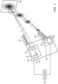
Fig. 1 is a schematic illustration of an electro-optical device with adaptive transmission power control, in accordance with an embodiment of the invention; -
Fig. 2 is a schematic representation of an emitted beam of pulses and a received beam of pulses, in accordance with an embodiment of the invention; and -
Fig. 3 is a block diagram that schematically illustrates a SPAD array and associated control and processing circuits, in accordance with an embodiment of the invention. - The quality of measurement of the distance to each point in a scene using a LiDAR is often compromised in practical implementations by a number of environmental, fundamental, and manufacturing challenges. An example of environmental challenges is the presence of uncorrelated background light, such as solar ambient light, in both indoor and outdoor applications, typically reaching a spectral irradiance of 1 W/(m2-nm). Fundamental challenges are related to losses incurred by optical signals upon reflection from the surfaces in the scene, especially due to low-reflectivity surfaces and limited optical collection aperture, as well as electronic and photon shot noises. These limitations often generate inflexible trade-off relationships that can push the designer to resort to solutions involving large optical apertures, high optical power, narrow field-of-view (FoV), bulky mechanical construction, low frame rate, and the restriction of sensors to operation in controlled environments.
- LiDAR systems in uncontrolled environments can suffer from problems of dynamic range due to the varying distances of reflectivities of obj ects from which the laser pulses reflect. High-intensity laser pulses are needed for distant and low-reflectivity objects, but will cause saturation of the detectors receiving radiation reflected from nearby and high-reflectivity objects. This saturation, in turn, causes a temporal bias error in the signal output by the detectors, which indicates the time of arrival of the pulse, and thus distort the corresponding time-of-flight determination. The bias error may reach 1ns, corresponding to an error in depth mapping of 15cm. Saturation of the detector array may also distort measurements of the reflectivity of the scene.
- Embodiments of the present invention that are described herein provide an electro-optical device functioning as a LiDAR, which is configured to adjust its laser power to prevent this sort of temporal bias error in the determination of time of arrival due to the saturation. Specifically, the laser power is adjusted based on monitoring the number of detectors responding to a given laser pulse, as an indicator of possible saturation. This adaptive adjustment of laser power can be useful in extending the dynamic range of the LiDAR, i.e., the range of distances over which the LiDAR gives reliable readings. Preventing saturation of the detector array also supports accurate readings of the scene reflectivities measured by the LiDAR.
- In the disclosed embodiments, the electro-optical device comprises a laser, an array of detectors, and a controller, which is coupled to the laser and to the detector array. The controller drives the laser to emit a sequence of pulses of optical radiation towards the scene, from which the pulses are reflected to the array of detectors. Each detector detecting a pulse emits a signal to the controller, with the signal indicating the time of arrival of the pulse. In order to scan the points in the scene, the electro-optical device may also comprise a scanner, coupled to the controller.
- The controller monitors the number of detectors from which it receives a signal for a given laser pulse, in order to detect a possible saturation of the detectors. As will be detailed below, the saturation of the responding detectors can result in distortion of the signal indicating the time of arrival, and this distortion introduces a bias error in the depth mapping. Thus, when the number of detectors outputting signals in response to a given pulse is greater than a predefined threshold, the controller reduces the power of subsequent pulses in the sequence in order to mitigate the saturation and thus achieve a more accurate ToF measurement.
- The detection of saturation is based on the fact that the laser pulse reflected from the scene extends over an area of the detector array and typically has Gaussian or other centrally-peaked spatial and temporal distributions of irradiance. Each detector in the array will typically respond more efficiently to the first photon of the reflected radiation that reaches it from a given laser pulse due to the effects of so-called dead time. (Dead time is defined as the recovery time a single-photon detector requires after having detected a photon in order to gain back its nominal detection efficiency.) Ideally, the arrival times of these photons will have a statistical spread corresponding to the spatial and temporal spreads of the pulse. As the laser intensity increases, the number of detectors "firing" (i.e., emitting an output signal indicating the detection of a photon) will increase; but the distribution should remain the same as long as there is no saturation. Thus, up to the saturation level, the number of firing detectors will scale roughly linearly with the peak power of the pulse.
- Saturation, on the other hand, will be characterized by an excessive number of firing detectors, as well as distortion of the apparent temporal distribution (and hence of the time of arrival measurement) as multiple photons are incident on at least some of the firing detectors. Temporal distortion is caused by dead time, as the probability of detecting a photon from the trailing portion of an optical pulse depends on the probability of not having detected any photon in the leading portion of the same pulse. Statistically, as the mean number of incident photons per pulse on each detector increases, the resulting temporal distribution of detected arrival times is skewed towards the leading edge of the pulse.
- Thus, the controller compares the number of firing detectors in response to each laser pulse to a certain threshold, which may be set empirically. If the comparison indicates that the detector array is not saturated, the controller derives the time-of-flight data from the signals received from the detector array, and calculates the scene depth. If, on the other hand, the comparison indicates a saturation of the detector array, the controller transmits to the laser a command to send the next pulse at a lower power. If the comparison in response to this next pulse still indicates saturation, the controller keeps attenuating the power of the laser in subsequent pulses until the detector array is no longer saturated. At this point the signals from the detector array are accepted as valid indications of time of arrival, and the scene depth is calculated using the time-of-flight data based on these signals.
- For the case in which the distance to a point in the scene is unknown (for instance, for the first depth measurement or in a scene that is changing dynamically), the first pulse toward a given point of the scene is emitted at the maximum emission power of the laser in order to receive a valid signal even if the point is distant or has low reflectivity. The controller then attenuates the power for subsequent pulses as necessary when the number of firing detectors is over threshold. The power may be attenuated in steps of a fixed, predetermined ratio by, for example, halving the laser power at each step. Alternatively, the controller may dynamically change the amount by which the power is attenuated by considering, for instance, the dead time of the single-photon detectors, the spatial extent of the unsaturated region in the detector array, and/or the extent of the scene.
- The above measurement sequence, in which the first pulse is emitted at the maximum emission power, may be repeated for each point of the scene. Alternatively, the final emission power directed to a given point may be used for neighboring points, with a reset to maximum emission power performed at a distance of a preset number of scan points from the given point.
- In some embodiments, the detector array comprises single-photon avalanche diodes (SPADs), which can be operated effectively in this manner. The description that follows will therefore relate specifically, for the sake of concreteness and clarity, to SPAD arrays, but the principles of the present invention may similarly be applied to detectors of other types.
- In order to synchronize the detection of the received pulses with the scanning of the scene, the controller may dynamically activate a subset of the SPADs in the SPAD array such that this subset encompasses the present location of the reflected laser pulse that is imaged onto the array. (The region of sensitivity of the SPAD array may be selected and scanned along with the illumination spot by appropriately setting the bias voltages of the SPADs in synchronization with the scanning of the laser beam, as described, for example, in
U.S. Patent Application 14/975,790, filed December 20, 2015 - In an environment where additional electro-optical devices emit high-power laser pulses, one of these pulses may accidentally reach the detector array of the LiDAR and saturate it. The controller of the LiDAR may interpret this saturation to be due to the emitted laser power of the LiDAR itself, and will consequently lower its laser power. In an embodiment, for avoiding such an erroneous action, the LiDAR may be equipped with the capability of making its decisions to lower the laser power based on two or three consecutively received laser pulses, rather than just one.
- Although the embodiments described hereinbelow use a single threshold on the number of firing detectors in deciding whether to lower the laser pulse intensity, in an alternative embodiment, multiple thresholds can be defined for enabling several levels of response. Each threshold may be assigned a different ratio of power attenuation, and the power is attenuated by the ratio assigned to the highest exceeded threshold. Attenuating the laser power by an amount dependent on the exceeded threshold will, in the case of high level of saturation, adjust the laser power faster to an acceptable level. In the case of a low saturation level, a too-drastic attenuation of the laser power is avoided.
-
Fig. 1 is a schematic illustration of an electro-optical device 20 with adaptive transmission power control, in accordance with an embodiment of the invention. Electro-optical device 20 comprises alight source 22, areceiver 24, and acontroller 26, which is coupled tolight source 22 and toreceiver 24. (The term "light" as used herein refers to optical radiation, which may be in any of the visible, infrared and ultraviolet ranges.)Light source 22 comprises alaser 28 and ascanner 30.Receiver 24 comprisescollection optics 32 and aSPAD array 34. -
Controller 26 driveslaser 28 to emit pulses of optical radiation, which are projected byscanner 30 as an emitted beam ofpulses 36 and scanned, under the control ofcontroller 26, across ascene 38.Scene 38 is shown here, for the sake of simplicity, as an abstract flat surface, but in general, the scene that is mapped has a more complex and possibly dynamic topology. A portion of emitted beam ofpulses 36 is reflected towardsreceiver 24 as a received beam ofpulses 40. Received beam ofpulses 40 is collected bycollection optics 32 and imaged to alocation 42 onSPAD array 34. - At the beginning of the depth measurement sequence for a given point in
scene 38,controller 26drives laser 28 to emit a pulse at a predefined maximum emission power.Controller 26, in conjunction with drivingscanner 30, activates a subset of SPADs (not shown) aroundlocation 42 inSPAD array 34, so that received beam ofpulses 40 is completely within this subset of SPADs.Controller 26 receives the signals output by the activated subset of SPADs, and determines whether the number of firing SPADs in the subset is saturated or not by comparing the number of firing SPADs to a predetermined threshold. - When the number exceeds the threshold,
controller 26 determines that the SPAD array is saturated, and commandslaser 28 to emit the next pulse at a lower emission power. Againcontroller 26 compares the number of firing SPADs to the predetermined threshold, and adjusts the emission power oflaser 28, until such a level of emission power is reached that the number of firing SPADs in the subset is below the saturation threshold. At this point in the sequence of pulses,controller 26 accepts the signals from the subset of SPADs as valid signals for a time-of-flight measurement, and estimates the depth of the illuminated point inscene 38 on this basis.Controller 26 may instructlaser 28 to emit multiple pulses at this level and make multiple, successive depth measurements on this basis, at the same point or subsequent points of the scan. - As
scanner 30 continues to scan the emitted beam ofpulses 36 overscene 38,controller 26 periodically resets the emission power oflaser 28 to the maximum. For example, the laser power may be reset afterlocation 42 onSPAD array 34 has moved by 6-7 SPADs. The process of power adjustment described above is then repeated. - Although
controller 26 is shown, for the sake of simplicity, as a separate, unitary element, inpractice controller 26 may comprise distributed processing components that are integrated withSPAD array 34. The SPAD array typically comprises integrated sensing and processing circuits, as described, for example, inU.S. Patent Application 14/830,760, filed August 20, 2015 U.S. Patent Application 14/975,790 . -
Fig. 2 is a schematic illustration of emitted beam ofpulses 36 and received beam of pulses 40 (referring to the elements shown inFig. 1 ), in accordance with an embodiment of the invention. Received beam ofpulses 40 is shifted from the emitted beam ofpulses 36 by the amount of time of flight tTOF. This figure illustrates the possible effect of saturation on measured time of flight, which is mitigated by the techniques described herein. - For demonstrating the effect of the saturation, the signal received by
controller 26 from the activated subset of SPADs inlocation 42 from a single receivedpulse 48 is shown schematically. Aframe 50 shows two examples of signals: Asignal 52 from a non-saturated subset of SPADs, and a signal 54 from a saturated subset of SPADs.Signal 52 is obtained whenpulse 48 is sufficiently low, due to an appropriate match between the distance to the measured point onscene 38 and the emission power of the emitted pulse. Signal 54 is obtained when the power of the emitted pulse resulting in receivedpulse 48 is too high, due to too high an emission power oflaser 28 for a given distance to the measured point ofscene 38. The narrow and shifted profile of signal 54 as compared to signal 52 is due to most or all of the activated SPADs firing in a very short time due to the leading photons of a high-irradiance receivedpulse 48. The difference between the times of arrival determined fromsignals 52 and 54 is abias error 56, whose magnitude depends on the power of receivedpulse 48. The value ofbias error 56 may reach 1ns, which translates into a 1ns error in the determination of time of arrival, which, in turn, translates into an error of 15cm in the determination of the depth ofscene 38 at the measured point. -
Fig. 3 is a block diagram that schematically illustratesSPAD array 34 and associated control and processing circuits, in accordance with an embodiment of the invention. The illustrated circuits process signals fromSPAD array 34 and control laser 28 (Fig. 1 ). The control and processing circuits shown inFig. 3 can be considered to be components ofcontroller 26 that is shown inFig. 1 . - A
detector chip 58 comprisesSPAD array 34, along with elements ofcontroller 26 including apipeline adder 64, a (digital)comparator 66, apulse generator 68, digital signal processing (DSP)circuitry 70, andreadout circuitry 72. A laser driver chip 73 comprises a drivecurrent controller 74. Aprocessor 96 is coupled to detector chip 58 (with coupling tocomparator 66, topulse generator 68, and toreadout circuitry 72 explicitly shown), to laser driver chip 73, and to scanner 30 (not shown). Withindetector chip 58,pipeline adder 64 is coupled to selectively read outSPADs 79 that are within thecurrent subset 78 ofSPAD array 34, and feeds the results tocomparator 66, and toDSP circuitry 70.Comparator 66 is further coupled, either viaprocessor 96 or directly, topulse generator 68 which, in turn, is coupled tolaser drive controller 74 and toprocessor 96.DSP circuitry 70 is further coupled toreadout circuitry 72, which, in turn, is coupled to aprocessor 96. - Alternatively,
processor 96 is coupled to laser drivercurrent controller 74, thus obviating the need forcoupling pulse generator 68 to laser drivercurrent controller 74. In order to reduce the timing latency betweencomparator 66 and laser drivercurrent controller 74,pulse generator 66 can be directly coupled to laser drivercurrent controller 74.Pulse generator 68 provides an interface function by whichdetector chip 58 outputs a voltage or current pulse with a finite duration that can be easily detected by laser drivercurrent controller 74 andprocessor 96. The interface function ofpulse generator 68 avoids possible problems that could result from the voltage pulses at the output ofcomparator 66 being too short for propagatingoutside detector chip 58. - Further referring to the elements shown in
Fig. 1 , emitted beam ofpulses 36 is emitted, by a command fromcontroller 26, bylaser 28, and reflected byscene 38 as received beam ofpulses 40. Received beam ofpulses 40 illuminates the area ofSPAD array 34 atlocation 42. While controllingscanner 30 to define the direction of emitted beam ofpulses 36,controller 26 also activates the correspondingsubset 78 ofSPAD array 34 aroundlocation 42, and configures the inputs topipeline adder 64 to be connected toSPADs 79 insubset 78. - When a pulse of received beam of
pulses 40 is received bySPAD array 34,pipeline adder 64 adds the number of SPADs insubset 78 that have fired (not explicitly shown among SPADs 79), and transmits the number as anumerical signal 80 to an input ofcomparator 66. The other input tocomparator 66 is athreshold 82 determined byprocessor 96. Ifcomparator 66 determines thatsignal 80 exceedssignal 82, i.e., the number of firing SPADs insubset 78 is higher than the threshold determined by the controller (indicating saturation of subset 78), the comparator issues acommand signal 84 topulse generator 68.Pulse generator 68, upon receivingsignal 84, issues an adaptivepower control signal 86 to drivecurrent controller 74, which, in response, attenuates a laser drive current 88 by an amount determined byprocessor 96. Onceprocessor 96, by monitoring the above signals, determines that the number of firing SPADs insubset 78 is not saturated and consequently no further attenuating of laser drive current 88 is required, it reads anoutput signal 90 fromreadout circuitry 72, which now represents a valid time-of-flight signal. - Referring to emitted beam of
pulses 36 and received beam ofpulses 40 inFig. 3 , a first emittedpulse 36a is emitted bylaser 28 at its highest power, generating a first receivedpulse 40a. In the present example, first receivedpulse 40a saturates the number of firing SPADs insubset 78. This causes the power of a second emittedpulse 36b to be attenuated by a predetermined attenuation factor, such as a factor of two, through the above-mentioned circuitry and signal processing, causing a second receivedpulse 40b to be a factor of two lower in power than first receivedpulse 40a. In the embodiment shown inFig. 3 , second receivedpulse 40b still saturates the number of firing SPADs insubset 78, requiring another halving of the pulse power. The resulting third receivedpulse 40c no longer saturates the number of firing SPADs insubset 78, and signal 90 is accepted byprocessor 96 as a valid signal of time of flight. In the pictured example, three additional emittedpulses 36d are emitted bylaser 28 at the same power as emittedpulse 36c, resulting in receivedpulses 40d, for increasing the signal-to-noise ratio (SNR) in time-of-flight signal 90. - ToF measurements of high-intensity pulses showing signs of saturation may simply be discarded, as explained above, but alternatively, these saturated measurements may be incorporated into the depth map at certain points. For example, at an edge in a scene between nearby and more distant targets, reflections of high-intensity pulses from the closer target will cause saturation, but may still provide useful ToF information with regard to the more distant target. To handle this sort of situation, ToF measurements for longer distances can be accumulated following the high-intensity pulses even in cases of saturation. These high-intensity measurements can be combined with lower-intensity, non-saturated measurements of shorter distances in order to enhance edge resolution in the depth map.
- Although the disclosed embodiment uses a factor of two for attenuating the power of successive emitted
pulses 36, other factors, as well as other sequences, for attenuating the power of emittedpulses 36 can be used in alternative embodiments of the invention. Alternatively,processor 96 may dynamically change the amount by which the power is attenuated by considering, for instance, the dead time of the SPADs, the spatial extent of the unsaturated region insubset 78, and/or the extent ofscene 38. - Although the embodiments described hereinabove relate specifically to arrays of SPADs, the principles of the present invention may similarly be applied to other types of single-photon detectors, as well as other radiation sensors operating in Geiger mode. It will thus be appreciated that the embodiments described above are cited by way of example, and that the present invention is not limited to what has been particularly shown and described hereinabove. Rather, the scope of the present invention includes both combinations and subcombinations of the various features described hereinabove, as well as variations and modifications thereof which would occur to persons skilled in the art upon reading the foregoing description and which are not disclosed in the prior art.
Claims (15)
- An electro-optical device (20), comprising:a laser (28), which is configured to emit toward a scene (38) pulses (36) of optical radiation;an array (34) of single-photon detectors (79), which are configured to receive the optical radiation that is reflected from points in the scene (38) and to fire, upon detecting a photon, an output signal indicative of a respective time of arrival of the detected photon, such that up to a saturation level, a number of the single-photon detectors firing in response to a pulse of the optical radiation scales roughly linearly with a power of the pulse; anda controller (26), which is coupled to drive the laser (28) to emit a sequence of the pulses (36) of the optical radiation toward each of a plurality of points in the scene (38) and to find respective times of flight for the points responsively to output signals fired by the single-photon detectors, while controlling the power of the pulses (36) emitted by the laser (28) by counting the number of the single-photon detectors (79) firing in response to each pulse, and when the number of the single-photon detectors (79) firing in response to a given pulse is greater than a predefined threshold, reducing the power of a subsequent pulse in the sequence.
- The electro-optical device (20) according to claim 1, wherein the single-photon detectors (79) are single-photon avalanche detectors, SPADs.
- The electro-optical device (20) according to claim 1, wherein the controller (26) is configured to reduce the power of the subsequent pulse in the sequence by at least one predetermined attenuation factor.
- The electro-optical device (20) according to claim 3, wherein the controller (26) is configured to attenuate the power of subsequent pulses (36) in multiple steps of a predetermined ratio until the number of the single-photon detectors (79) firing falls below the predefined threshold.
- The electro-optical device (20) according to any of claims 1-4, and comprising a scanner configured to scan the pulses (36) of optical radiation across the scene (38).
- The electro-optical device (20) according to claim 5, wherein the controller (26) is configured to construct a depth map of the scene (38) based on the respective time of flight found at the plurality of points while scanning the pulses (36).
- The electro-optical device (20) according to claim 5, wherein the controller (26) is configured to activate a respective subset of the detectors (79) at a location in the array (34) that receives the reflected optical radiation at each point in synchronization with scanning the pulses (36).
- The electro-optical device (20) according to claim 5, wherein the controller (26) is configured to set the power of the pulses (36) at some of the points to the reduced power that was used at a preceding point while scanning the pulses (36).
- The electro-optical device (20) according to any of claims 1-4, wherein the controller (26) comprises:an adder, which is coupled to receive the signals from the single-photon detectors (79) and to output a numerical signal indicative of the number of the single-photon detectors (79) firing;a comparator, which is configured to compare the numerical signal from the adder to the predetermined threshold and to generate a command signal when the signal exceeds the predetermined threshold; anda pulse generator, which generates, in response to the command signal, an adaptive power control signal, which controls a drive current of the laser (28) responsively to the adaptive power control signal.
- A method for sensing, comprising:emitting a sequence of pulses (36) of optical radiation toward each of a plurality of points in a scene (38);receiving the optical radiation that is reflected from points in the scene (38) in an array (34) of single-photon detectors (79), which fire, upon detecting a photon, an output signal indicative of a respective time of arrival of the detected photon, such that up to a saturation level, a number of the single-photon detectors firing in response to a pulse of the optical radiation scales roughly linearly with a power of the pulse;finding respective times of flight for the points responsively to output signals fired by the single-photon detectors; andcontrolling the power of the emitted pulses (36) by counting the number of the single-photon detectors (79) firing in response to each pulse, and when the number of the single-photon detectors (79) firing in response to a given pulse is greater than a predefined threshold, reducing the power of a subsequent pulse in the sequence.
- The method according to claim 10, wherein the single-photon detectors (79) are single-photon avalanche detectors, SPADs.
- The method according to claim 10, wherein controlling the power comprises reducing the power of the subsequent pulse in the sequence by at least one predetermined attenuation factor.
- The method according to claim 12, wherein reducing the power comprises attenuating the power of subsequent pulses (36) in multiple steps of a predetermined ratio until the number of the detectors (79) firing falls below the predefined threshold.
- The method according to any of claims 10-13, wherein emitting the sequence of pulses comprises scanning the pulses (36) of optical radiation across the scene (38).
- The method according to any of claims 10-13, wherein controlling the power comprises:receiving the signals from the single-photon detectors (79) and outputting a numerical signal indicative of the number of the single-photon detectors (79) outputting signals;comparing the numerical signal to the predetermined threshold and generating a command signal when the signal exceeds the predetermined threshold; andgenerating, in response to the command signal, an adaptive power control signal, which controls a drive current of a laser emitting the pulses (36).
Applications Claiming Priority (2)
| Application Number | Priority Date | Filing Date | Title |
|---|---|---|---|
| US201662397943P | 2016-09-22 | 2016-09-22 | |
| PCT/US2017/040648 WO2018057085A1 (en) | 2016-09-22 | 2017-07-05 | Adaptive transmission power control for a lidar |
Publications (2)
| Publication Number | Publication Date |
|---|---|
| EP3516415A1 EP3516415A1 (en) | 2019-07-31 |
| EP3516415B1 true EP3516415B1 (en) | 2024-12-04 |
Family
ID=59366514
Family Applications (1)
| Application Number | Title | Priority Date | Filing Date |
|---|---|---|---|
| EP17740850.7A Active EP3516415B1 (en) | 2016-09-22 | 2017-07-05 | Adaptive transmission power control for a lidar |
Country Status (4)
| Country | Link |
|---|---|
| US (1) | US10775507B2 (en) |
| EP (1) | EP3516415B1 (en) |
| CN (1) | CN109791195B (en) |
| WO (1) | WO2018057085A1 (en) |
Families Citing this family (68)
| Publication number | Priority date | Publication date | Assignee | Title |
|---|---|---|---|---|
| US12399279B1 (en) | 2016-02-15 | 2025-08-26 | Red Creamery Llc | Enhanced hybrid LIDAR with high-speed scanning |
| US12399278B1 (en) | 2016-02-15 | 2025-08-26 | Red Creamery Llc | Hybrid LIDAR with optically enhanced scanned laser |
| US12123950B2 (en) | 2016-02-15 | 2024-10-22 | Red Creamery, LLC | Hybrid LADAR with co-planar scanning and imaging field-of-view |
| US11556000B1 (en) | 2019-08-22 | 2023-01-17 | Red Creamery Llc | Distally-actuated scanning mirror |
| US10502574B2 (en) * | 2016-09-20 | 2019-12-10 | Waymo Llc | Devices and methods for a sensor platform of a vehicle |
| US10277084B1 (en) | 2016-10-19 | 2019-04-30 | Waymo Llc | Planar rotary transformer |
| US11346952B2 (en) | 2017-12-08 | 2022-05-31 | Hesai Technology Co., Ltd. | Systems and methods for light detection and ranging |
| US10340408B1 (en) | 2018-05-17 | 2019-07-02 | Hi Llc | Non-invasive wearable brain interface systems including a headgear and a plurality of self-contained photodetector units configured to removably attach to the headgear |
| US10515993B2 (en) | 2018-05-17 | 2019-12-24 | Hi Llc | Stacked photodetector assemblies |
| US10158038B1 (en) | 2018-05-17 | 2018-12-18 | Hi Llc | Fast-gated photodetector architectures comprising dual voltage sources with a switch configuration |
| JP7290632B2 (en) * | 2018-05-24 | 2023-06-13 | ソニーセミコンダクタソリューションズ株式会社 | time measuring device |
| CN108562910A (en) * | 2018-06-15 | 2018-09-21 | 安徽科创中光科技有限公司 | A kind of laser radar of the anti-stop signal saturation distortion of heavy haze weather |
| US10420498B1 (en) | 2018-06-20 | 2019-09-24 | Hi Llc | Spatial and temporal-based diffusive correlation spectroscopy systems and methods |
| US11213206B2 (en) | 2018-07-17 | 2022-01-04 | Hi Llc | Non-invasive measurement systems with single-photon counting camera |
| WO2020092953A1 (en) * | 2018-11-02 | 2020-05-07 | Waymo Llc | Synchronization of multiple rotating sensors of a vehicle |
| WO2020131148A1 (en) | 2018-12-21 | 2020-06-25 | Hi Llc | Biofeedback for awareness and modulation of mental state using a non-invasive brain interface system and method |
| US12038510B2 (en) | 2019-01-04 | 2024-07-16 | Sense Photonics, Inc. | High dynamic range direct time of flight sensor with signal-dependent effective readout rate |
| AU2020268718B2 (en) | 2019-05-06 | 2025-04-03 | Hi Llc | Photodetector architectures for time-correlated single photon counting |
| WO2020236371A1 (en) | 2019-05-21 | 2020-11-26 | Hi Llc | Photodetector architectures for efficient fast-gating |
| CA3137921A1 (en) | 2019-06-06 | 2020-12-10 | Hi Llc | Photodetector systems with low-power time-to-digital converter architectures |
| US11500094B2 (en) * | 2019-06-10 | 2022-11-15 | Apple Inc. | Selection of pulse repetition intervals for sensing time of flight |
| US12306307B2 (en) | 2019-06-10 | 2025-05-20 | Apple Inc. | Selection of pulse repetition intervals for sensing time of flight |
| DE102019215951A1 (en) * | 2019-10-16 | 2021-04-22 | Robert Bosch Gmbh | Method, computer program, electronic storage medium and device for evaluating optical received signals |
| US11733359B2 (en) | 2019-12-03 | 2023-08-22 | Apple Inc. | Configurable array of single-photon detectors |
| US11740333B2 (en) | 2019-12-04 | 2023-08-29 | Waymo Llc | Pulse energy plan for light detection and ranging (lidar) devices based on areas of interest and thermal budgets |
| US11969259B2 (en) | 2020-02-21 | 2024-04-30 | Hi Llc | Detector assemblies for a wearable module of an optical measurement system and including spring-loaded light-receiving members |
| US12029558B2 (en) | 2020-02-21 | 2024-07-09 | Hi Llc | Time domain-based optical measurement systems and methods configured to measure absolute properties of tissue |
| US11771362B2 (en) | 2020-02-21 | 2023-10-03 | Hi Llc | Integrated detector assemblies for a wearable module of an optical measurement system |
| US12144653B2 (en) | 2020-02-21 | 2024-11-19 | Hi Llc | Systems, circuits, and methods for reducing common-mode noise in biopotential recordings |
| WO2021167876A1 (en) | 2020-02-21 | 2021-08-26 | Hi Llc | Methods and systems for initiating and conducting a customized computer-enabled brain research study |
| US11630310B2 (en) | 2020-02-21 | 2023-04-18 | Hi Llc | Wearable devices and wearable assemblies with adjustable positioning for use in an optical measurement system |
| US11950879B2 (en) | 2020-02-21 | 2024-04-09 | Hi Llc | Estimation of source-detector separation in an optical measurement system |
| US11883181B2 (en) | 2020-02-21 | 2024-01-30 | Hi Llc | Multimodal wearable measurement systems and methods |
| WO2021167890A1 (en) | 2020-02-21 | 2021-08-26 | Hi Llc | Wearable module assemblies for an optical measurement system |
| US12138068B2 (en) | 2020-03-20 | 2024-11-12 | Hi Llc | Techniques for characterizing a nonlinearity of a time-to-digital converter in an optical measurement system |
| WO2021188488A1 (en) | 2020-03-20 | 2021-09-23 | Hi Llc | Bias voltage generation in an optical measurement system |
| US11187575B2 (en) | 2020-03-20 | 2021-11-30 | Hi Llc | High density optical measurement systems with minimal number of light sources |
| US11245404B2 (en) | 2020-03-20 | 2022-02-08 | Hi Llc | Phase lock loop circuit based signal generation in an optical measurement system |
| US11857348B2 (en) | 2020-03-20 | 2024-01-02 | Hi Llc | Techniques for determining a timing uncertainty of a component of an optical measurement system |
| US11877825B2 (en) | 2020-03-20 | 2024-01-23 | Hi Llc | Device enumeration in an optical measurement system |
| US12059262B2 (en) | 2020-03-20 | 2024-08-13 | Hi Llc | Maintaining consistent photodetector sensitivity in an optical measurement system |
| WO2021188487A1 (en) | 2020-03-20 | 2021-09-23 | Hi Llc | Temporal resolution control for temporal point spread function generation in an optical measurement system |
| US11645483B2 (en) | 2020-03-20 | 2023-05-09 | Hi Llc | Phase lock loop circuit based adjustment of a measurement time window in an optical measurement system |
| US11903676B2 (en) | 2020-03-20 | 2024-02-20 | Hi Llc | Photodetector calibration of an optical measurement system |
| US11864867B2 (en) | 2020-03-20 | 2024-01-09 | Hi Llc | Control circuit for a light source in an optical measurement system by applying voltage with a first polarity to start an emission of a light pulse and applying voltage with a second polarity to stop the emission of the light pulse |
| US11819311B2 (en) | 2020-03-20 | 2023-11-21 | Hi Llc | Maintaining consistent photodetector sensitivity in an optical measurement system |
| US12059270B2 (en) | 2020-04-24 | 2024-08-13 | Hi Llc | Systems and methods for noise removal in an optical measurement system |
| CN111708040B (en) * | 2020-06-02 | 2023-08-11 | Oppo广东移动通信有限公司 | Distance measuring device, distance measuring method and electronic equipment |
| CN111983630B (en) * | 2020-08-18 | 2024-03-29 | Oppo广东移动通信有限公司 | Single photon ranging system, method, terminal equipment and storage medium |
| GB202013579D0 (en) * | 2020-08-28 | 2020-10-14 | Ams Int Ag | Dynamic range extension of spad-based devices |
| CN112147626A (en) * | 2020-09-14 | 2020-12-29 | Oppo广东移动通信有限公司 | Electronic device, control method of electronic device, and computer-readable storage medium |
| CN112612015A (en) * | 2020-12-08 | 2021-04-06 | 广东博智林机器人有限公司 | Laser radar system |
| US12442926B2 (en) | 2021-02-04 | 2025-10-14 | Apple Inc. | Time-of-flight depth sensing with improved linearity |
| CN112986962B (en) * | 2021-02-21 | 2023-10-10 | 中山大学 | Transmitting power adjusting circuit and method applied to laser transmitting module |
| US12196860B2 (en) | 2021-03-02 | 2025-01-14 | Apple Inc. | Depth sensor calibration using internal reflections |
| JP7721938B2 (en) * | 2021-03-25 | 2025-08-13 | 富士フイルムビジネスイノベーション株式会社 | Detection device, detection program, and optical device |
| DE102021203464A1 (en) | 2021-04-08 | 2022-10-13 | Robert Bosch Gesellschaft mit beschränkter Haftung | Procedure for operating a LiDAR system |
| US11435453B1 (en) | 2021-04-15 | 2022-09-06 | Aeva, Inc. | Techniques for simultaneous determination of range and velocity with active modulation |
| CN115728746A (en) * | 2021-08-26 | 2023-03-03 | 上海禾赛科技有限公司 | Laser radar and method for three-dimensional detection using laser radar |
| CN113777584A (en) * | 2021-09-06 | 2021-12-10 | 上海惚恍微电子科技有限公司 | Apparatus and method for automatically controlling signal strength of direct time-of-flight sensing system |
| CN114019478B (en) * | 2021-09-22 | 2025-01-28 | 深圳阜时科技有限公司 | Optical detection devices and electronic equipment |
| EP4418006A4 (en) | 2021-11-12 | 2025-03-05 | Samsung Electronics Co., Ltd. | Signal control method and wearable device supporting same |
| CN116338647B (en) * | 2021-12-23 | 2024-08-16 | 深圳市速腾聚创科技有限公司 | Radar system, echo signal processing method and device and electronic equipment |
| CN116973881A (en) * | 2022-04-24 | 2023-10-31 | 深圳市速腾聚创科技有限公司 | Target detection method, laser radar and storage medium |
| CN115097472A (en) * | 2022-05-18 | 2022-09-23 | 传周半导体科技(上海)有限公司 | A high-speed lidar system |
| CN117269972B (en) * | 2022-06-14 | 2024-09-27 | 深圳市速腾聚创科技有限公司 | Laser radar device and ranging adjustment method thereof |
| CN117665762A (en) * | 2022-08-22 | 2024-03-08 | 上海禾赛科技有限公司 | Lidar and its emission energy adjustment method and adjustment system |
| CN119716810B (en) * | 2023-09-28 | 2025-12-02 | 深圳市速腾聚创科技有限公司 | Laser signal emission method, apparatus and computer-readable storage medium |
Family Cites Families (18)
| Publication number | Priority date | Publication date | Assignee | Title |
|---|---|---|---|---|
| US4240746A (en) * | 1979-08-06 | 1980-12-23 | Her Majesty The Queen In Right Of Canada, As Represented By The Minister Of National Defense | System for transmitter frequency control in coherent ladar |
| JPH11352226A (en) * | 1998-06-09 | 1999-12-24 | Nec Corp | High precision distance measuring device |
| US20030227614A1 (en) | 2002-06-05 | 2003-12-11 | Taminiau August A. | Laser machining apparatus with automatic focusing |
| WO2008008970A2 (en) * | 2006-07-13 | 2008-01-17 | Velodyne Acoustics, Inc | High definition lidar system |
| DE102009029372A1 (en) * | 2009-09-11 | 2011-03-24 | Robert Bosch Gmbh | Measuring device for measuring a distance between the measuring device and a target object by means of optical measuring radiation |
| DE102010003843A1 (en) * | 2010-04-12 | 2011-10-13 | Robert Bosch Gmbh | Distance measuring device with homogenizing measurement evaluation |
| EP2469301A1 (en) * | 2010-12-23 | 2012-06-27 | André Borowski | Methods and devices for generating a representation of a 3D scene at very high speed |
| FR2984522B1 (en) * | 2011-12-20 | 2014-02-14 | St Microelectronics Grenoble 2 | DEVICE FOR DETECTING THE PROXIMITY OF AN OBJECT, COMPRISING SPAD PHOTODIODS |
| GB2510890A (en) * | 2013-02-18 | 2014-08-20 | St Microelectronics Res & Dev | Method and apparatus |
| CN103293947A (en) * | 2013-05-16 | 2013-09-11 | 中国科学院上海天文台 | Satellite-ground laser time comparison system |
| GB2514576A (en) * | 2013-05-29 | 2014-12-03 | St Microelectronics Res & Dev | Methods and apparatus |
| JP5889484B2 (en) * | 2013-05-29 | 2016-03-22 | 三菱電機株式会社 | Laser radar apparatus and radar image generation method |
| US9312401B2 (en) * | 2014-01-15 | 2016-04-12 | Omnivision Technologies, Inc. | Single photon avalanche diode imaging sensor for complementary metal oxide semiconductor stacked chip applications |
| US9331116B2 (en) * | 2014-01-15 | 2016-05-03 | Omnivision Technologies, Inc. | Back side illuminated single photon avalanche diode imaging sensor with high short wavelength detection efficiency |
| CA2959335A1 (en) * | 2014-08-26 | 2016-03-03 | Massachusetts Institute Of Technology | Methods and apparatus for three-dimensional (3d) imaging |
| CN104833979B (en) * | 2015-04-27 | 2017-03-15 | 北京航天控制仪器研究所 | A kind of method of the signal transacting of laser ranging and laser ranging data |
| US10620300B2 (en) | 2015-08-20 | 2020-04-14 | Apple Inc. | SPAD array with gated histogram construction |
| US9997551B2 (en) * | 2015-12-20 | 2018-06-12 | Apple Inc. | Spad array with pixel-level bias control |
-
2017
- 2017-07-05 CN CN201780057761.2A patent/CN109791195B/en active Active
- 2017-07-05 WO PCT/US2017/040648 patent/WO2018057085A1/en not_active Ceased
- 2017-07-05 EP EP17740850.7A patent/EP3516415B1/en active Active
- 2017-08-10 US US15/673,428 patent/US10775507B2/en active Active
Also Published As
| Publication number | Publication date |
|---|---|
| EP3516415A1 (en) | 2019-07-31 |
| WO2018057085A1 (en) | 2018-03-29 |
| CN109791195B (en) | 2023-02-03 |
| CN109791195A (en) | 2019-05-21 |
| US20180081061A1 (en) | 2018-03-22 |
| US10775507B2 (en) | 2020-09-15 |
Similar Documents
| Publication | Publication Date | Title |
|---|---|---|
| US10775507B2 (en) | Adaptive transmission power control for a LIDAR | |
| EP3751307B1 (en) | Selection of pulse repetition intervals for sensing time of flight | |
| KR102364531B1 (en) | Noise Adaptive Solid-State LIDAR System | |
| US20180081041A1 (en) | LiDAR with irregular pulse sequence | |
| EP3704510B1 (en) | Time-of-flight sensing using an addressable array of emitters | |
| US10739445B2 (en) | Parallel photon counting | |
| CN107085218B (en) | Method for determining the return time of a return light pulse and SPL scanner | |
| CN109212538B (en) | Time-of-flight depth mapping with disparity compensation | |
| KR20220145845A (en) | Noise Filtering Systems and Methods for Solid State LiDAR | |
| US9417326B2 (en) | Pulsed light optical rangefinder | |
| US20200158831A1 (en) | Imaging system with synchronized scan and sensing | |
| US10324171B2 (en) | Light detection and ranging sensor | |
| CN113424077B (en) | Optical distance measuring device | |
| CN111919137A (en) | Noise adaptive solid state LIDAR system | |
| EP3391076A1 (en) | Light detection and ranging sensor | |
| US20230375678A1 (en) | Photoreceiver having thresholded detection | |
| CN111796295B (en) | Collector, manufacturing method of collector and distance measuring system | |
| CA2716980A1 (en) | Light-integrating rangefinding device and method | |
| US20230007979A1 (en) | Lidar with photon-resolving detector | |
| US11681028B2 (en) | Close-range measurement of time of flight using parallax shift | |
| EP4303625A1 (en) | Lidar system and method to operate |
Legal Events
| Date | Code | Title | Description |
|---|---|---|---|
| STAA | Information on the status of an ep patent application or granted ep patent |
Free format text: STATUS: UNKNOWN |
|
| STAA | Information on the status of an ep patent application or granted ep patent |
Free format text: STATUS: THE INTERNATIONAL PUBLICATION HAS BEEN MADE |
|
| PUAI | Public reference made under article 153(3) epc to a published international application that has entered the european phase |
Free format text: ORIGINAL CODE: 0009012 |
|
| STAA | Information on the status of an ep patent application or granted ep patent |
Free format text: STATUS: REQUEST FOR EXAMINATION WAS MADE |
|
| 17P | Request for examination filed |
Effective date: 20190418 |
|
| AK | Designated contracting states |
Kind code of ref document: A1 Designated state(s): AL AT BE BG CH CY CZ DE DK EE ES FI FR GB GR HR HU IE IS IT LI LT LU LV MC MK MT NL NO PL PT RO RS SE SI SK SM TR |
|
| AX | Request for extension of the european patent |
Extension state: BA ME |
|
| DAV | Request for validation of the european patent (deleted) | ||
| DAX | Request for extension of the european patent (deleted) | ||
| STAA | Information on the status of an ep patent application or granted ep patent |
Free format text: STATUS: EXAMINATION IS IN PROGRESS |
|
| 17Q | First examination report despatched |
Effective date: 20210920 |
|
| REG | Reference to a national code |
Ref country code: DE Ref legal event code: R079 Free format text: PREVIOUS MAIN CLASS: G01S0007484000 Ipc: G01S0017100000 Ref country code: DE Ref legal event code: R079 Ref document number: 602017086540 Country of ref document: DE Free format text: PREVIOUS MAIN CLASS: G01S0007484000 Ipc: G01S0017100000 |
|
| RIC1 | Information provided on ipc code assigned before grant |
Ipc: G01S 7/486 20060101ALI20240621BHEP Ipc: G01S 7/484 20060101ALI20240621BHEP Ipc: G02F 1/29 20060101ALI20240621BHEP Ipc: G01S 7/4865 20200101ALI20240621BHEP Ipc: G01S 7/4863 20200101ALI20240621BHEP Ipc: G01S 17/10 20060101AFI20240621BHEP |
|
| GRAP | Despatch of communication of intention to grant a patent |
Free format text: ORIGINAL CODE: EPIDOSNIGR1 |
|
| STAA | Information on the status of an ep patent application or granted ep patent |
Free format text: STATUS: GRANT OF PATENT IS INTENDED |
|
| INTG | Intention to grant announced |
Effective date: 20240802 |
|
| GRAS | Grant fee paid |
Free format text: ORIGINAL CODE: EPIDOSNIGR3 |
|
| GRAA | (expected) grant |
Free format text: ORIGINAL CODE: 0009210 |
|
| STAA | Information on the status of an ep patent application or granted ep patent |
Free format text: STATUS: THE PATENT HAS BEEN GRANTED |
|
| AK | Designated contracting states |
Kind code of ref document: B1 Designated state(s): AL AT BE BG CH CY CZ DE DK EE ES FI FR GB GR HR HU IE IS IT LI LT LU LV MC MK MT NL NO PL PT RO RS SE SI SK SM TR |
|
| REG | Reference to a national code |
Ref country code: GB Ref legal event code: FG4D |
|
| REG | Reference to a national code |
Ref country code: CH Ref legal event code: EP |
|
| REG | Reference to a national code |
Ref country code: DE Ref legal event code: R096 Ref document number: 602017086540 Country of ref document: DE |
|
| REG | Reference to a national code |
Ref country code: IE Ref legal event code: FG4D |
|
| REG | Reference to a national code |
Ref country code: LT Ref legal event code: MG9D |
|
| REG | Reference to a national code |
Ref country code: NL Ref legal event code: MP Effective date: 20241204 |
|
| PG25 | Lapsed in a contracting state [announced via postgrant information from national office to epo] |
Ref country code: HR Free format text: LAPSE BECAUSE OF FAILURE TO SUBMIT A TRANSLATION OF THE DESCRIPTION OR TO PAY THE FEE WITHIN THE PRESCRIBED TIME-LIMIT Effective date: 20241204 |
|
| PG25 | Lapsed in a contracting state [announced via postgrant information from national office to epo] |
Ref country code: FI Free format text: LAPSE BECAUSE OF FAILURE TO SUBMIT A TRANSLATION OF THE DESCRIPTION OR TO PAY THE FEE WITHIN THE PRESCRIBED TIME-LIMIT Effective date: 20241204 |
|
| PG25 | Lapsed in a contracting state [announced via postgrant information from national office to epo] |
Ref country code: BG Free format text: LAPSE BECAUSE OF FAILURE TO SUBMIT A TRANSLATION OF THE DESCRIPTION OR TO PAY THE FEE WITHIN THE PRESCRIBED TIME-LIMIT Effective date: 20241204 |
|
| PG25 | Lapsed in a contracting state [announced via postgrant information from national office to epo] |
Ref country code: ES Free format text: LAPSE BECAUSE OF FAILURE TO SUBMIT A TRANSLATION OF THE DESCRIPTION OR TO PAY THE FEE WITHIN THE PRESCRIBED TIME-LIMIT Effective date: 20241204 |
|
| PG25 | Lapsed in a contracting state [announced via postgrant information from national office to epo] |
Ref country code: NO Free format text: LAPSE BECAUSE OF FAILURE TO SUBMIT A TRANSLATION OF THE DESCRIPTION OR TO PAY THE FEE WITHIN THE PRESCRIBED TIME-LIMIT Effective date: 20250304 |
|
| PG25 | Lapsed in a contracting state [announced via postgrant information from national office to epo] |
Ref country code: LV Free format text: LAPSE BECAUSE OF FAILURE TO SUBMIT A TRANSLATION OF THE DESCRIPTION OR TO PAY THE FEE WITHIN THE PRESCRIBED TIME-LIMIT Effective date: 20241204 Ref country code: GR Free format text: LAPSE BECAUSE OF FAILURE TO SUBMIT A TRANSLATION OF THE DESCRIPTION OR TO PAY THE FEE WITHIN THE PRESCRIBED TIME-LIMIT Effective date: 20250305 |
|
| PG25 | Lapsed in a contracting state [announced via postgrant information from national office to epo] |
Ref country code: RS Free format text: LAPSE BECAUSE OF FAILURE TO SUBMIT A TRANSLATION OF THE DESCRIPTION OR TO PAY THE FEE WITHIN THE PRESCRIBED TIME-LIMIT Effective date: 20250304 |
|
| PG25 | Lapsed in a contracting state [announced via postgrant information from national office to epo] |
Ref country code: NL Free format text: LAPSE BECAUSE OF FAILURE TO SUBMIT A TRANSLATION OF THE DESCRIPTION OR TO PAY THE FEE WITHIN THE PRESCRIBED TIME-LIMIT Effective date: 20241204 |
|
| REG | Reference to a national code |
Ref country code: AT Ref legal event code: MK05 Ref document number: 1748720 Country of ref document: AT Kind code of ref document: T Effective date: 20241204 |
|
| PG25 | Lapsed in a contracting state [announced via postgrant information from national office to epo] |
Ref country code: SM Free format text: LAPSE BECAUSE OF FAILURE TO SUBMIT A TRANSLATION OF THE DESCRIPTION OR TO PAY THE FEE WITHIN THE PRESCRIBED TIME-LIMIT Effective date: 20241204 |
|
| PG25 | Lapsed in a contracting state [announced via postgrant information from national office to epo] |
Ref country code: PL Free format text: LAPSE BECAUSE OF FAILURE TO SUBMIT A TRANSLATION OF THE DESCRIPTION OR TO PAY THE FEE WITHIN THE PRESCRIBED TIME-LIMIT Effective date: 20241204 |
|
| PG25 | Lapsed in a contracting state [announced via postgrant information from national office to epo] |
Ref country code: IS Free format text: LAPSE BECAUSE OF FAILURE TO SUBMIT A TRANSLATION OF THE DESCRIPTION OR TO PAY THE FEE WITHIN THE PRESCRIBED TIME-LIMIT Effective date: 20250404 |
|
| PG25 | Lapsed in a contracting state [announced via postgrant information from national office to epo] |
Ref country code: PT Free format text: LAPSE BECAUSE OF FAILURE TO SUBMIT A TRANSLATION OF THE DESCRIPTION OR TO PAY THE FEE WITHIN THE PRESCRIBED TIME-LIMIT Effective date: 20250404 |
|
| PG25 | Lapsed in a contracting state [announced via postgrant information from national office to epo] |
Ref country code: EE Free format text: LAPSE BECAUSE OF FAILURE TO SUBMIT A TRANSLATION OF THE DESCRIPTION OR TO PAY THE FEE WITHIN THE PRESCRIBED TIME-LIMIT Effective date: 20241204 |
|
| PG25 | Lapsed in a contracting state [announced via postgrant information from national office to epo] |
Ref country code: AT Free format text: LAPSE BECAUSE OF FAILURE TO SUBMIT A TRANSLATION OF THE DESCRIPTION OR TO PAY THE FEE WITHIN THE PRESCRIBED TIME-LIMIT Effective date: 20241204 Ref country code: RO Free format text: LAPSE BECAUSE OF FAILURE TO SUBMIT A TRANSLATION OF THE DESCRIPTION OR TO PAY THE FEE WITHIN THE PRESCRIBED TIME-LIMIT Effective date: 20241204 |
|
| PG25 | Lapsed in a contracting state [announced via postgrant information from national office to epo] |
Ref country code: SK Free format text: LAPSE BECAUSE OF FAILURE TO SUBMIT A TRANSLATION OF THE DESCRIPTION OR TO PAY THE FEE WITHIN THE PRESCRIBED TIME-LIMIT Effective date: 20241204 |
|
| PG25 | Lapsed in a contracting state [announced via postgrant information from national office to epo] |
Ref country code: CZ Free format text: LAPSE BECAUSE OF FAILURE TO SUBMIT A TRANSLATION OF THE DESCRIPTION OR TO PAY THE FEE WITHIN THE PRESCRIBED TIME-LIMIT Effective date: 20241204 |
|
| PG25 | Lapsed in a contracting state [announced via postgrant information from national office to epo] |
Ref country code: IT Free format text: LAPSE BECAUSE OF FAILURE TO SUBMIT A TRANSLATION OF THE DESCRIPTION OR TO PAY THE FEE WITHIN THE PRESCRIBED TIME-LIMIT Effective date: 20241204 |
|
| REG | Reference to a national code |
Ref country code: DE Ref legal event code: R097 Ref document number: 602017086540 Country of ref document: DE |
|
| PG25 | Lapsed in a contracting state [announced via postgrant information from national office to epo] |
Ref country code: SE Free format text: LAPSE BECAUSE OF FAILURE TO SUBMIT A TRANSLATION OF THE DESCRIPTION OR TO PAY THE FEE WITHIN THE PRESCRIBED TIME-LIMIT Effective date: 20241204 |
|
| PG25 | Lapsed in a contracting state [announced via postgrant information from national office to epo] |
Ref country code: DK Free format text: LAPSE BECAUSE OF FAILURE TO SUBMIT A TRANSLATION OF THE DESCRIPTION OR TO PAY THE FEE WITHIN THE PRESCRIBED TIME-LIMIT Effective date: 20241204 |
|
| PLBE | No opposition filed within time limit |
Free format text: ORIGINAL CODE: 0009261 |
|
| STAA | Information on the status of an ep patent application or granted ep patent |
Free format text: STATUS: NO OPPOSITION FILED WITHIN TIME LIMIT |
|
| REG | Reference to a national code |
Ref country code: CH Ref legal event code: L10 Free format text: ST27 STATUS EVENT CODE: U-0-0-L10-L00 (AS PROVIDED BY THE NATIONAL OFFICE) Effective date: 20251015 |
|
| 26N | No opposition filed |
Effective date: 20250905 |
|
| REG | Reference to a national code |
Ref country code: DE Ref legal event code: R119 Ref document number: 602017086540 Country of ref document: DE |
|
| REG | Reference to a national code |
Ref country code: CH Ref legal event code: H13 Free format text: ST27 STATUS EVENT CODE: U-0-0-H10-H13 (AS PROVIDED BY THE NATIONAL OFFICE) Effective date: 20260224 |
|
| PG25 | Lapsed in a contracting state [announced via postgrant information from national office to epo] |
Ref country code: LU Free format text: LAPSE BECAUSE OF NON-PAYMENT OF DUE FEES Effective date: 20250705 |
|
| GBPC | Gb: european patent ceased through non-payment of renewal fee |
Effective date: 20250705 |
|
| REG | Reference to a national code |
Ref country code: BE Ref legal event code: MM Effective date: 20250731 |
|
| PG25 | Lapsed in a contracting state [announced via postgrant information from national office to epo] |
Ref country code: GB Free format text: LAPSE BECAUSE OF NON-PAYMENT OF DUE FEES Effective date: 20250705 |
|
| PG25 | Lapsed in a contracting state [announced via postgrant information from national office to epo] |
Ref country code: DE Free format text: LAPSE BECAUSE OF NON-PAYMENT OF DUE FEES Effective date: 20260203 |
|
| PG25 | Lapsed in a contracting state [announced via postgrant information from national office to epo] |
Ref country code: BE Free format text: LAPSE BECAUSE OF NON-PAYMENT OF DUE FEES Effective date: 20250731 |
|
| PG25 | Lapsed in a contracting state [announced via postgrant information from national office to epo] |
Ref country code: FR Free format text: LAPSE BECAUSE OF NON-PAYMENT OF DUE FEES Effective date: 20250731 |
|
| PG25 | Lapsed in a contracting state [announced via postgrant information from national office to epo] |
Ref country code: CH Free format text: LAPSE BECAUSE OF NON-PAYMENT OF DUE FEES Effective date: 20250731 |