EP3516405B1 - Voltage indicator display module - Google Patents
Voltage indicator display module Download PDFInfo
- Publication number
- EP3516405B1 EP3516405B1 EP17777717.4A EP17777717A EP3516405B1 EP 3516405 B1 EP3516405 B1 EP 3516405B1 EP 17777717 A EP17777717 A EP 17777717A EP 3516405 B1 EP3516405 B1 EP 3516405B1
- Authority
- EP
- European Patent Office
- Prior art keywords
- well body
- display module
- battery
- plug
- communication
- Prior art date
- Legal status (The legal status is an assumption and is not a legal conclusion. Google has not performed a legal analysis and makes no representation as to the accuracy of the status listed.)
- Active
Links
Images



Classifications
-
- G—PHYSICS
- G01—MEASURING; TESTING
- G01R—MEASURING ELECTRIC VARIABLES; MEASURING MAGNETIC VARIABLES
- G01R13/00—Arrangements for displaying electric variables or waveforms
- G01R13/40—Arrangements for displaying electric variables or waveforms using modulation of a light beam otherwise than by mechanical displacement, e.g. by Kerr effect
-
- G—PHYSICS
- G01—MEASURING; TESTING
- G01R—MEASURING ELECTRIC VARIABLES; MEASURING MAGNETIC VARIABLES
- G01R19/00—Arrangements for measuring currents or voltages or for indicating presence or sign thereof
- G01R19/145—Indicating the presence of current or voltage
- G01R19/155—Indicating the presence of voltage
-
- H—ELECTRICITY
- H01—ELECTRIC ELEMENTS
- H01M—PROCESSES OR MEANS, e.g. BATTERIES, FOR THE DIRECT CONVERSION OF CHEMICAL ENERGY INTO ELECTRICAL ENERGY
- H01M10/00—Secondary cells; Manufacture thereof
- H01M10/42—Methods or arrangements for servicing or maintenance of secondary cells or secondary half-cells
- H01M10/48—Accumulators combined with arrangements for measuring, testing or indicating the condition of cells, e.g. the level or density of the electrolyte
- H01M10/488—Cells or batteries combined with indicating means for external visualization of the condition, e.g. by change of colour or of light density
-
- Y—GENERAL TAGGING OF NEW TECHNOLOGICAL DEVELOPMENTS; GENERAL TAGGING OF CROSS-SECTIONAL TECHNOLOGIES SPANNING OVER SEVERAL SECTIONS OF THE IPC; TECHNICAL SUBJECTS COVERED BY FORMER USPC CROSS-REFERENCE ART COLLECTIONS [XRACs] AND DIGESTS
- Y02—TECHNOLOGIES OR APPLICATIONS FOR MITIGATION OR ADAPTATION AGAINST CLIMATE CHANGE
- Y02E—REDUCTION OF GREENHOUSE GAS [GHG] EMISSIONS, RELATED TO ENERGY GENERATION, TRANSMISSION OR DISTRIBUTION
- Y02E60/00—Enabling technologies; Technologies with a potential or indirect contribution to GHG emissions mitigation
- Y02E60/10—Energy storage using batteries
Definitions
- This application is generally related to voltage indicators and specifically to display modules for voltage indicators that allow for access to electronics without exposing a user to high voltages.
- Voltage indicators that provide a positive indication of a lack of voltage typically need a power source other than the power source that is being monitored by the voltage indicator.
- One method of providing this source of power is through a battery. However, occasionally that battery will need to be replaced and it would be desirable to be able to replace the battery without removing power from the source being monitored and without exposing a user to high voltages while replacing the battery.
- VeriSafe Absence of Voltage Tester 8 September 2016, pages 1-8, XP055428324 (http://www.panduit.com/ccurl/399/131/abense-of-voltage-detector-sfcb06.0.pdf ) discloses a test device designed to verify that a circuit is de-energized prior to opening an electrical enclosure containing energized conductors and circuit devices.
- VeriSafe Absence of Voltage Tester 1 March 2016, pages 1-15, XP055428328 (http://nsrp.org/wp-content/uploads/2017/03/05-VeriSafe-External-Overview.pdf ) also discloses a test device designed to verify that a circuit is de-energized prior to opening an electrical enclosure containing energized conductors and circuit devices.
- WO 2016/036952 A1 discloses a method and device for determining the absence of voltage in electrical equipment.
- An installed device is electrically connected to a power source.
- the installed device has circuitry capable of detecting voltage, performing self-diagnostics, and testing for connectivity to the power source.
- the device can also check to see if the voltage is at a deenergized level, recheck for continuity and repeat the self-diagnostics.
- a voltage display module for a voltage indication device has a well body, communication cable, cap, and battery shuttle.
- the well body is secured to the door of the electrical enclosure.
- the communication plug of the communication cable is secured to the well body.
- the cap is removably secured to the well body and is accessible to a user from outside the enclosure.
- the battery shuttle is housed within the well body and has a communication jack secured to one end. The communication jack is configured to engage the communication plug when the battery shuttle is fully inserted and configured to be electrically isolated from the plug when the battery shuttle is partially withdrawn.
- the voltage indication device 10 product consists of two separate enclosures that house the electronics used to perform the voltage absence verification.
- the DIN module 300 is an enclosure that houses one or more circuit assemblies. These circuit assemblies provide the voltage measurement and system check functions.
- the DIN module 300 is designed to be mounted on DIN rail or surface mounted inside of the electrical enclosure 200 to keep hazardous voltage away from the door.
- the display module 100 will be mounted on the door 210 of the enclosure 200 and will provide means to initiate the test sequence and visually see indication of the results.
- the display module 100 will contain the battery that is needed to support the test functions and a circuit assembly needed to facilitate the test initiating and results reporting functions.
- the design will provide means to change the battery from the enclosure door without entering the electrical enclosure or giving exposure to the potentially hazardous levels of electrical energy being monitored by the product.
- Figure 2 shows a front view and an isometric view of the display module 100.
- a test button 102 is pressed by the user to initiate the verification tests.
- a test status indicator 103 is illuminated by a yellow LED to indicate that a test is in progress and/or test failure.
- a green LED 104 will illuminate green to indicate that the test has verified the absence of voltage below a defined threshold as well as proper connection and function of the device.
- Red LEDs 105 will illuminate to show presence of voltage over a certain threshold on each of the lines in a 3 phase system.
- Figure 3 shows the display module 100 installed in a control panel or electrical enclosure 200. Note that some of the display module 100 will be accessible outside of the electrical enclosure 200 and some will be inside the electrical enclosure 200.
- FIG 4 is an exploded view of the display module 100.
- the display module 100 includes a cap 110, faceplate 111, battery 112, well body 113, compression washer 116, and battery shuttle 114.
- the cap 110 is used to retain and position the battery shuttle 114 and faceplate 111.
- the battery shuttle 114 is housed in the well body 113 and slides out to give the user access to the battery, which will require replacement at the end of its life.
- the battery shuttle 114 can also house the circuit assemblies (see Figure 8 ) and faceplate 111.
- the compression washer 116 functions with the cap 110 and provides a spring-type resistance when installing.
- the well body 113 houses the battery shuttle 114, RJ45 plug retention features and features used to mount the display module to the electrical enclosure door panel 210.
- the well body 113 is designed to be installed in a standard 30mm knockout, typical in electrical enclosures.
- the faceplate 111 can house the LED lights, push button and graphics overlay.
- a battery shuttle o-ring 117 is used to seal the battery shuttle 114 to the well body 113. This will prevent water ingress to the well body 113 that contains the battery 112 and electronics.
- a mounting nut 118 can be used to fasten the well body housing 113 to the electrical enclosure panel 200.
- a sealing gasket 119 can be used to seal the well body 113 to the electrical enclosure door panel 210; this can help to prevent water ingress to the electrical enclosure 200.
- a well body flange 120 can be used to back up both the sealing gasket 119 and the compression washer 116.
- Figure 5 also shows a network cable 400, which can be a 600V CAT5E cable, that can be used to transmit low-voltage signals from the DIN module 300 to the display module 100.
- the network cable 400 can also conduct power from the battery 112 (in the display module 100) to the DIN module 300 to be used for the various tests performed by the circuits in the DIN module in order to verify proper function, connection and absence of voltage.
- an RJ45 jack assembly 150 is permanently mounted on a display module circuit assembly 130 housed on the battery shuttle 114.
- This circuit assembly 130, along with the RJ45 jack assembly 150 is permanently fixed to the battery shuttle 114.
- the RJ45 plug 401 can have a 90-degree strain relief that routes the cable 400 perpendicular to the orientation of the well body 113, which minimizes intrusion into the electrical enclosure 200.
- the RJ45 plug 401 is secured to the well body 113 with a separate latching component, plug retention clip 123 (see Figure 9 ).
- the RJ45 plug 401 is not secured to the RJ45 jack assembly 150 as would be the case with a typical RJ45 assembly. Due to having the plug retention clip 123 on the well body 113 instead of the RJ45 jack assembly 150, the battery shuttle 114 can be partially withdrawn from the well body 113 while the RJ45 plug 401 stays fixed in place to the well body 113 (See Figure 7 ). When the battery shuttle 114 is partially withdrawn, the RJ45 jack assembly 150 is disengaged from the RJ45 plug 401, making the display module 100 effectively electrically isolated from the DIN module 300 helping to eliminate any exposure to harmful electrical energy that could be derived from the DIN module 300.
- FIG 7 shows the battery shuttle 114 in the open position, and the resulting disconnection of the RJ45 jack assembly 150 from the RJ45 plug 401.
- the battery shuttle 114 travel is limited by interference features 124 built into the shuttle 114 and the battery shuttle retention ring 129 (see Figure 8 ).
- the battery shuttle 114 can be removable from the well body 113 with tools when the user has access to the entire display module 100. However, generally speaking, the battery shuttle 114 is not intended to be removed from the well body 113 during normal operation. It is designed to extend enough for the user to access and remove the battery.
- the plug retention clip 123 is a component that is secured to the well body 113 and holds the RJ45 plug 401 in a fixed position to the well body 113. This is accomplished with a plug retention catch 127 that engages an opening in the RJ45 plug 401.
- the latching component 123 is designed so it can be flexed to withdraw the latching component catch 127 and allow the RJ45 plug 401 to be removed from the well body 113. This allows a user to remove the RJ45 plug 401 and replace the RJ45 cable 400.
- the cap 110 retains the battery shuttle 114 in the fully inserted position and therefore keeps the RJ45 jack assembly 150 fully engaged and connected to the RJ45 plug 401.
- the cap 110 is installed by aligning the cap engagement boss 141 in the well body ramped cap engagement slot 143 and rotating the cap 110 to draw it in towards the compression washer 116.
- the compression washer 116 provides a spring type resistance to the cap 110, increasing the torque required to move over the well body cap retention bump 145.
- the well body cap retention bump 150 along with the compression washer 116 serves as resistance to rotating the cap 110 in the counterclockwise direction for removal.
- the well body cap rotation limit boss 147 limits the rotation of the cap 110.
- Figure 13 shows and alternate design for cap retention.
- the well body 113 has a series of cap retention tabs 177.
- the cap engagement bosses 141 interfere with the cap retention tabs 177 and the cap will flex for the cap engagement bosses 141 to ride over the cap retention tabs 177.
- the cap engagement bosses 141 will have to ride back over the cap retention tabs 177. This interference fit increases the torque required to remove the cap 110, which will hold it securely in place.
Landscapes
- Physics & Mathematics (AREA)
- General Physics & Mathematics (AREA)
- Engineering & Computer Science (AREA)
- Manufacturing & Machinery (AREA)
- Chemical & Material Sciences (AREA)
- Chemical Kinetics & Catalysis (AREA)
- Electrochemistry (AREA)
- General Chemical & Material Sciences (AREA)
- Battery Mounting, Suspending (AREA)
- Structure Of Receivers (AREA)
- Charge And Discharge Circuits For Batteries Or The Like (AREA)
Description
- This application is generally related to voltage indicators and specifically to display modules for voltage indicators that allow for access to electronics without exposing a user to high voltages.
- Voltage indicators that provide a positive indication of a lack of voltage typically need a power source other than the power source that is being monitored by the voltage indicator. One method of providing this source of power is through a battery. However, occasionally that battery will need to be replaced and it would be desirable to be able to replace the battery without removing power from the source being monitored and without exposing a user to high voltages while replacing the battery.
- "VeriSafe Absence of Voltage Tester", 8 September 2016, pages 1-8, XP055428324 (http://www.panduit.com/ccurl/399/131/abense-of-voltage-detector-sfcb06.0.pdf) discloses a test device designed to verify that a circuit is de-energized prior to opening an electrical enclosure containing energized conductors and circuit devices.
- "VeriSafe Absence of Voltage Tester", 1 March 2016, pages 1-15, XP055428328 (http://nsrp.org/wp-content/uploads/2017/03/05-VeriSafe-External-Overview.pdf) also discloses a test device designed to verify that a circuit is de-energized prior to opening an electrical enclosure containing energized conductors and circuit devices.
-
WO 2016/036952 A1 discloses a method and device for determining the absence of voltage in electrical equipment. An installed device is electrically connected to a power source. The installed device has circuitry capable of detecting voltage, performing self-diagnostics, and testing for connectivity to the power source. In one embodiment, the device can also check to see if the voltage is at a deenergized level, recheck for continuity and repeat the self-diagnostics. - A voltage display module for a voltage indication device has a well body, communication cable, cap, and battery shuttle. The well body is secured to the door of the electrical enclosure. The communication plug of the communication cable is secured to the well body. The cap is removably secured to the well body and is accessible to a user from outside the enclosure. The battery shuttle is housed within the well body and has a communication jack secured to one end. The communication jack is configured to engage the communication plug when the battery shuttle is fully inserted and configured to be electrically isolated from the plug when the battery shuttle is partially withdrawn.
-
-
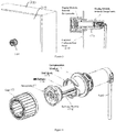
Figure 1 shows an isometric view of a voltage detection device with a display module and a DIN module installed within an electrical enclosure. -
Figure 2 is a front view and an isometric view of the display module ofFigure 1 . -
Figure 3 is a perspective view and a cross-sectional view of the display module ofFigure 2 installed on a door panel of an electrical enclosure. -
Figure 4 is a partially exploded isometric view of the display module ofFigure 2 , -
Figure 5 is a side view of the display module ofFigure 2 . -
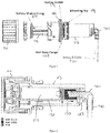
Figure 6 is a cross-sectional view of the display module ofFigure 2 . -
Figure 7 is a cross-sectional view of the display module ofFigure 2 with the battery shuttle partially withdrawn. -
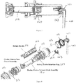
Figure 8 is an exploded isometric view of the display module ofFigure 8 . -
Figure 9 is an isometric and cross-sectional view of the display module ofFigure 2 , highlighting the plug retention clip. -
Figure 10 is cross-sectional views of the display module ofFigure 2 highlighting the plug retention clip. -
Figure 11 is perspective views of the display module ofFigure 2 demonstrating the partial withdrawal of the battery shuttle. -
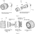
Figure 12 is a side view and perspective view showing how the cap is secured to the well body. -
Figure 13 is a side view showing an additional method of securing the cap to the well body. - This disclosure describes the
display module 100 design for avoltage indication device 10. As shown inFigure 1 , thevoltage indication device 10 product consists of two separate enclosures that house the electronics used to perform the voltage absence verification. - The
DIN module 300 is an enclosure that houses one or more circuit assemblies. These circuit assemblies provide the voltage measurement and system check functions. TheDIN module 300 is designed to be mounted on DIN rail or surface mounted inside of theelectrical enclosure 200 to keep hazardous voltage away from the door. - The
display module 100 will be mounted on thedoor 210 of theenclosure 200 and will provide means to initiate the test sequence and visually see indication of the results. In addition, thedisplay module 100 will contain the battery that is needed to support the test functions and a circuit assembly needed to facilitate the test initiating and results reporting functions. The design will provide means to change the battery from the enclosure door without entering the electrical enclosure or giving exposure to the potentially hazardous levels of electrical energy being monitored by the product. -
Figure 2 shows a front view and an isometric view of thedisplay module 100. InFigure 2 , atest button 102 is pressed by the user to initiate the verification tests. Atest status indicator 103 is illuminated by a yellow LED to indicate that a test is in progress and/or test failure. Agreen LED 104 will illuminate green to indicate that the test has verified the absence of voltage below a defined threshold as well as proper connection and function of the device.Red LEDs 105 will illuminate to show presence of voltage over a certain threshold on each of the lines in a 3 phase system. -
Figure 3 shows thedisplay module 100 installed in a control panel orelectrical enclosure 200. Note that some of thedisplay module 100 will be accessible outside of theelectrical enclosure 200 and some will be inside theelectrical enclosure 200. -
Figure 4 is an exploded view of thedisplay module 100. In one embodiment, thedisplay module 100 includes acap 110, faceplate 111,battery 112,well body 113,compression washer 116, andbattery shuttle 114. Thecap 110 is used to retain and position thebattery shuttle 114 and faceplate 111. Thebattery shuttle 114 is housed in thewell body 113 and slides out to give the user access to the battery, which will require replacement at the end of its life. Thebattery shuttle 114 can also house the circuit assemblies (seeFigure 8 ) and faceplate 111. The compression washer 116 functions with thecap 110 and provides a spring-type resistance when installing. Thewell body 113 houses thebattery shuttle 114, RJ45 plug retention features and features used to mount the display module to the electricalenclosure door panel 210. Thewell body 113 is designed to be installed in a standard 30mm knockout, typical in electrical enclosures. The faceplate 111 can house the LED lights, push button and graphics overlay. - As shown in
Figure 5 , a battery shuttle o-ring 117 is used to seal thebattery shuttle 114 to thewell body 113. This will prevent water ingress to thewell body 113 that contains thebattery 112 and electronics. Amounting nut 118 can be used to fasten thewell body housing 113 to theelectrical enclosure panel 200. A sealing gasket 119 can be used to seal thewell body 113 to the electricalenclosure door panel 210; this can help to prevent water ingress to theelectrical enclosure 200. A wellbody flange 120 can be used to back up both the sealing gasket 119 and thecompression washer 116.Figure 5 also shows anetwork cable 400, which can be a 600V CAT5E cable, that can be used to transmit low-voltage signals from theDIN module 300 to thedisplay module 100. These signals can include the button press to initiate the test and signals to light the various LED indicators. Thenetwork cable 400 can also conduct power from the battery 112 (in the display module 100) to theDIN module 300 to be used for the various tests performed by the circuits in the DIN module in order to verify proper function, connection and absence of voltage. - As shown in the cross-sectional view of
Figure 6 , the connection between thedisplay module 100 and thenetwork cable 400 is facilitated by an RJ45 jack and RJ45 plug assembly. In this case, anRJ45 jack assembly 150 is permanently mounted on a displaymodule circuit assembly 130 housed on thebattery shuttle 114. Thiscircuit assembly 130, along with theRJ45 jack assembly 150 is permanently fixed to thebattery shuttle 114. TheRJ45 plug 401 can have a 90-degree strain relief that routes thecable 400 perpendicular to the orientation of thewell body 113, which minimizes intrusion into theelectrical enclosure 200. TheRJ45 plug 401 is secured to thewell body 113 with a separate latching component, plug retention clip 123 (seeFigure 9 ). TheRJ45 plug 401 is not secured to theRJ45 jack assembly 150 as would be the case with a typical RJ45 assembly. Due to having theplug retention clip 123 on thewell body 113 instead of theRJ45 jack assembly 150, thebattery shuttle 114 can be partially withdrawn from thewell body 113 while theRJ45 plug 401 stays fixed in place to the well body 113 (SeeFigure 7 ). When thebattery shuttle 114 is partially withdrawn, theRJ45 jack assembly 150 is disengaged from theRJ45 plug 401, making thedisplay module 100 effectively electrically isolated from theDIN module 300 helping to eliminate any exposure to harmful electrical energy that could be derived from theDIN module 300. This is a key benefit of the invention described by this application as the RJ45 is a reliable and economical method of providing the eight separate conductors needed for the test and indication functionality while the sliding disconnect allows for a physical separation between the user-accessible components and the conductors that originate from circuitry that is in direct contact with dangerous levels of electrical energy. -
Figure 7 shows thebattery shuttle 114 in the open position, and the resulting disconnection of theRJ45 jack assembly 150 from theRJ45 plug 401. Thebattery shuttle 114 travel is limited by interference features 124 built into theshuttle 114 and the battery shuttle retention ring 129 (seeFigure 8 ). Thebattery shuttle 114 can be removable from thewell body 113 with tools when the user has access to theentire display module 100. However, generally speaking, thebattery shuttle 114 is not intended to be removed from thewell body 113 during normal operation. It is designed to extend enough for the user to access and remove the battery. - The
plug retention clip 123 is a component that is secured to thewell body 113 and holds theRJ45 plug 401 in a fixed position to thewell body 113. This is accomplished with aplug retention catch 127 that engages an opening in theRJ45 plug 401. Thelatching component 123 is designed so it can be flexed to withdraw thelatching component catch 127 and allow theRJ45 plug 401 to be removed from thewell body 113. This allows a user to remove theRJ45 plug 401 and replace theRJ45 cable 400. - As shown in
Figures 11 and 12 , thecap 110 retains thebattery shuttle 114 in the fully inserted position and therefore keeps theRJ45 jack assembly 150 fully engaged and connected to theRJ45 plug 401. Thecap 110 is installed by aligning thecap engagement boss 141 in the well body rampedcap engagement slot 143 and rotating thecap 110 to draw it in towards thecompression washer 116. Thecompression washer 116 provides a spring type resistance to thecap 110, increasing the torque required to move over the well bodycap retention bump 145. The well bodycap retention bump 150 along with thecompression washer 116 serves as resistance to rotating thecap 110 in the counterclockwise direction for removal. The well body caprotation limit boss 147 limits the rotation of thecap 110. -
Figure 13 shows and alternate design for cap retention. In this design, thewell body 113 has a series of cap retention tabs 177. When the user twists thecap 110 onto thewell body 113, thecap engagement bosses 141 interfere with the cap retention tabs 177 and the cap will flex for thecap engagement bosses 141 to ride over the cap retention tabs 177. In order to remove the cap, thecap engagement bosses 141 will have to ride back over the cap retention tabs 177. This interference fit increases the torque required to remove thecap 110, which will hold it securely in place. - While particular embodiments and applications of the present invention have been illustrated and described, it is to be understood that the invention is not limited to the precise construction and compositions disclosed herein and that various modifications, changes, and variations may be apparent from the foregoing without departing from the scope of the invention as described.
Claims (7)
- A voltage display module (100) for a voltage indication device (10) for mounting to a door (210) of an electrical enclosure (200) comprising:a well body (113) secured to the door of the electrical enclosure wherein a portion of the well body is contained within the enclosure;a communication cable (400) with a communication plug (401), the communication plug being secured to the well body;a removable cap (110) secured to the well body, the cap being accessible by a user from outside the electrical enclosure;a battery shuttle (114) housed within the well body, the battery shuttle having a communication jack (150) secured to it, characterised in that the communication jack is configured to engage the communication plug when the battery shuttle is fully inserted into the well body, the well body and communication jack being further configured to electrically isolate the communication jack from the communication plug when the battery shuttle is at least partially withdrawn from the well body.
- The voltage display module (100) of claim 1 wherein the battery shuttle (114) and well body (113) contain a retention feature (129) preventing the complete removal of the battery shuttle from the well body.
- The voltage display module (100) of claim 1 wherein the communication plug (401) is secured to the well body via a retention clip (123).
- The voltage display module (100) of claim 1 wherein the communication jack (150) is an RJ45 style jack.
- The voltage display module (100) of claim 4 wherein the communication plug (401) is an RJ45 style plug.
- The voltage display module (100) of claim 1 wherein the cap (110) must be removed before the battery shuttle (114) may be partially withdrawn.
- The voltage display module (100) of claim 1 wherein the battery shuttle (114) further comprises electronics, the electronics being electrically isolated from the communication plug (401) when the battery shuttle is partially withdrawn from the well body (113).
Applications Claiming Priority (2)
| Application Number | Priority Date | Filing Date | Title |
|---|---|---|---|
| US201662396467P | 2016-09-19 | 2016-09-19 | |
| PCT/US2017/051977 WO2018053386A1 (en) | 2016-09-19 | 2017-09-18 | Voltage indicator display module |
Publications (2)
| Publication Number | Publication Date |
|---|---|
| EP3516405A1 EP3516405A1 (en) | 2019-07-31 |
| EP3516405B1 true EP3516405B1 (en) | 2020-07-15 |
Family
ID=59997458
Family Applications (1)
| Application Number | Title | Priority Date | Filing Date |
|---|---|---|---|
| EP17777717.4A Active EP3516405B1 (en) | 2016-09-19 | 2017-09-18 | Voltage indicator display module |
Country Status (10)
| Country | Link |
|---|---|
| US (1) | US11378593B2 (en) |
| EP (1) | EP3516405B1 (en) |
| JP (1) | JP7196065B2 (en) |
| KR (1) | KR102191790B1 (en) |
| CN (1) | CN210136266U (en) |
| AU (1) | AU2017329013B2 (en) |
| CA (1) | CA3037310C (en) |
| MX (1) | MX387787B (en) |
| TW (1) | TWI739905B (en) |
| WO (1) | WO2018053386A1 (en) |
Families Citing this family (2)
| Publication number | Priority date | Publication date | Assignee | Title |
|---|---|---|---|---|
| US11709187B2 (en) * | 2021-03-19 | 2023-07-25 | Panduit Corp. | Methods to initiate the absence of voltage test over a network remotely |
| US20230351355A1 (en) * | 2022-04-27 | 2023-11-02 | 6Success | Cloud-based contactless vending machine |
Family Cites Families (19)
| Publication number | Priority date | Publication date | Assignee | Title |
|---|---|---|---|---|
| US3141128A (en) | 1961-06-26 | 1964-07-14 | Samuel H Behr | Apparatus for testing portable equipment for a. c. and d. c. leakage and for ground continuity |
| JPS5368031U (en) * | 1976-11-11 | 1978-06-08 | ||
| US4870343A (en) | 1988-07-26 | 1989-09-26 | Public Service Electric & Gas Co. | High voltage detector |
| JP3318772B2 (en) | 1992-04-15 | 2002-08-26 | ソニー株式会社 | Secondary battery pack and method of manufacturing the same |
| FR2723486A1 (en) | 1994-08-05 | 1996-02-09 | Catu Ets | SINGLE VOLTAGE SENSOR, IN PARTICULAR FOR AERIAL ELECTRIC LINE |
| US5867019A (en) | 1996-10-23 | 1999-02-02 | Bmf Engineering Inc. | Power cable voltage tester |
| US5986557A (en) | 1998-03-10 | 1999-11-16 | Automatic Timing & Controls, Inc. | Three-phase fuse status indicator |
| US6703938B1 (en) | 2002-09-27 | 2004-03-09 | Automatic Timing & Controls, Inc. | Electrical panel safety monitor |
| WO2005047714A1 (en) * | 2003-11-17 | 2005-05-26 | Telezygology Inc | Fasteners and other assemblies |
| ITRM20050201A1 (en) | 2005-04-29 | 2006-10-30 | Bticino Spa | SUPPORT CHASSIS FOR THE WALL MOUNTING OF AN ELECTRIC APPLIANCE. |
| US7319315B2 (en) | 2005-09-08 | 2008-01-15 | Jefferson Science Associates, Llc | Voltage verification unit |
| US8013613B2 (en) | 2005-12-08 | 2011-09-06 | Grace Engineered Products, Inc. | Voltage indicator test mechanism |
| JP4764994B2 (en) * | 2007-06-28 | 2011-09-07 | 富士電機株式会社 | Signal relay device |
| US8193447B2 (en) * | 2009-09-23 | 2012-06-05 | Peckham Albert E | Electrical outlet plate control arrangement |
| CA3035892C (en) * | 2010-07-02 | 2021-06-29 | Belkin International, Inc. | Systems and methods for measuring electrical power usage in a structure and systems and methods of calibrating the same |
| EP3084454B1 (en) | 2013-12-20 | 2021-02-17 | Panduit Corp. | Voltage indicator with continuity check |
| KR101635737B1 (en) * | 2014-09-03 | 2016-07-04 | 차보영 | The controlling system and the smart controller of a panel for solar power |
| WO2016036952A1 (en) | 2014-09-05 | 2016-03-10 | Panduit Corp. | Method and device for detecting the absence of voltage |
| US9726332B1 (en) * | 2016-02-09 | 2017-08-08 | Michael W. May | Networked LED lighting system |
-
2017
- 2017-09-18 MX MX2019002922A patent/MX387787B/en unknown
- 2017-09-18 US US16/330,644 patent/US11378593B2/en active Active
- 2017-09-18 KR KR1020197010186A patent/KR102191790B1/en active Active
- 2017-09-18 JP JP2019515510A patent/JP7196065B2/en active Active
- 2017-09-18 AU AU2017329013A patent/AU2017329013B2/en active Active
- 2017-09-18 CA CA3037310A patent/CA3037310C/en active Active
- 2017-09-18 EP EP17777717.4A patent/EP3516405B1/en active Active
- 2017-09-18 CN CN201790001251.9U patent/CN210136266U/en active Active
- 2017-09-18 TW TW106131937A patent/TWI739905B/en active
- 2017-09-18 WO PCT/US2017/051977 patent/WO2018053386A1/en not_active Ceased
Non-Patent Citations (1)
| Title |
|---|
| None * |
Also Published As
| Publication number | Publication date |
|---|---|
| AU2017329013B2 (en) | 2021-09-09 |
| CA3037310C (en) | 2024-04-30 |
| WO2018053386A9 (en) | 2018-05-17 |
| KR20190049825A (en) | 2019-05-09 |
| KR102191790B1 (en) | 2020-12-16 |
| EP3516405A1 (en) | 2019-07-31 |
| TWI739905B (en) | 2021-09-21 |
| CN210136266U (en) | 2020-03-10 |
| JP7196065B2 (en) | 2022-12-26 |
| WO2018053386A1 (en) | 2018-03-22 |
| US20210285986A1 (en) | 2021-09-16 |
| JP2019530864A (en) | 2019-10-24 |
| AU2017329013A1 (en) | 2019-03-28 |
| TW201825910A (en) | 2018-07-16 |
| MX2019002922A (en) | 2019-07-18 |
| MX387787B (en) | 2025-03-18 |
| CA3037310A1 (en) | 2018-03-22 |
| US11378593B2 (en) | 2022-07-05 |
Similar Documents
| Publication | Publication Date | Title |
|---|---|---|
| US8821167B2 (en) | Apparatus for electrically connecting a flexible circuit to a receiver | |
| US20130217276A1 (en) | Electrical wall bushing terminal | |
| US4575588A (en) | Universal telephone test apparatus | |
| EP3516405B1 (en) | Voltage indicator display module | |
| CA2811944C (en) | Meter socket with current bypass | |
| US11309669B2 (en) | Lug assemblies and related electrical apparatus and methods | |
| KR101833176B1 (en) | Current sensing module for photovoltaic connector band | |
| CN101548438A (en) | electrical connector | |
| RU180981U1 (en) | HIGH VOLTAGE PROTECTIVE DEVICE IN MODULAR DESIGN | |
| JP2019530864A5 (en) | ||
| JP2012114000A (en) | Plug for wiring duct | |
| JP2017207411A (en) | Terminal for testing | |
| US12573568B2 (en) | Power switch assembly having indicators and removable cover | |
| CN104871013A (en) | Current transformer and load interrupter having such a current transformer | |
| CN210464897U (en) | Locking detection device | |
| AU2012258431B2 (en) | Multifunctional changing device | |
| JP2007288833A (en) | Electrical connection appliance for test used for maintenance of apparatus, removable cover and electrical test method | |
| GB2488027A (en) | Electrical socket allowing testing | |
| Sorin et al. | Analysis of the modernized system for monitoring environmental parameters in workings with hazard of explosive atmospheres | |
| CA2875615A1 (en) | Apparatus for electrically connecting a flexible circuit to a receiver | |
| CN107636788A (en) | Converter system and the load break switch with converter system | |
| JP2014039344A (en) | Trip lock terminal and display plate used for the same |
Legal Events
| Date | Code | Title | Description |
|---|---|---|---|
| STAA | Information on the status of an ep patent application or granted ep patent |
Free format text: STATUS: UNKNOWN |
|
| STAA | Information on the status of an ep patent application or granted ep patent |
Free format text: STATUS: THE INTERNATIONAL PUBLICATION HAS BEEN MADE |
|
| PUAI | Public reference made under article 153(3) epc to a published international application that has entered the european phase |
Free format text: ORIGINAL CODE: 0009012 |
|
| STAA | Information on the status of an ep patent application or granted ep patent |
Free format text: STATUS: REQUEST FOR EXAMINATION WAS MADE |
|
| 17P | Request for examination filed |
Effective date: 20190320 |
|
| AK | Designated contracting states |
Kind code of ref document: A1 Designated state(s): AL AT BE BG CH CY CZ DE DK EE ES FI FR GB GR HR HU IE IS IT LI LT LU LV MC MK MT NL NO PL PT RO RS SE SI SK SM TR |
|
| AX | Request for extension of the european patent |
Extension state: BA ME |
|
| DAV | Request for validation of the european patent (deleted) | ||
| DAX | Request for extension of the european patent (deleted) | ||
| GRAP | Despatch of communication of intention to grant a patent |
Free format text: ORIGINAL CODE: EPIDOSNIGR1 |
|
| STAA | Information on the status of an ep patent application or granted ep patent |
Free format text: STATUS: GRANT OF PATENT IS INTENDED |
|
| INTG | Intention to grant announced |
Effective date: 20200211 |
|
| GRAS | Grant fee paid |
Free format text: ORIGINAL CODE: EPIDOSNIGR3 |
|
| GRAA | (expected) grant |
Free format text: ORIGINAL CODE: 0009210 |
|
| STAA | Information on the status of an ep patent application or granted ep patent |
Free format text: STATUS: THE PATENT HAS BEEN GRANTED |
|
| AK | Designated contracting states |
Kind code of ref document: B1 Designated state(s): AL AT BE BG CH CY CZ DE DK EE ES FI FR GB GR HR HU IE IS IT LI LT LU LV MC MK MT NL NO PL PT RO RS SE SI SK SM TR |
|
| REG | Reference to a national code |
Ref country code: CH Ref legal event code: EP Ref country code: GB Ref legal event code: FG4D |
|
| REG | Reference to a national code |
Ref country code: DE Ref legal event code: R096 Ref document number: 602017019920 Country of ref document: DE |
|
| REG | Reference to a national code |
Ref country code: IE Ref legal event code: FG4D |
|
| REG | Reference to a national code |
Ref country code: AT Ref legal event code: REF Ref document number: 1291611 Country of ref document: AT Kind code of ref document: T Effective date: 20200815 |
|
| REG | Reference to a national code |
Ref country code: LT Ref legal event code: MG4D |
|
| REG | Reference to a national code |
Ref country code: AT Ref legal event code: MK05 Ref document number: 1291611 Country of ref document: AT Kind code of ref document: T Effective date: 20200715 |
|
| REG | Reference to a national code |
Ref country code: NL Ref legal event code: MP Effective date: 20200715 |
|
| PG25 | Lapsed in a contracting state [announced via postgrant information from national office to epo] |
Ref country code: NO Free format text: LAPSE BECAUSE OF FAILURE TO SUBMIT A TRANSLATION OF THE DESCRIPTION OR TO PAY THE FEE WITHIN THE PRESCRIBED TIME-LIMIT Effective date: 20201015 Ref country code: ES Free format text: LAPSE BECAUSE OF FAILURE TO SUBMIT A TRANSLATION OF THE DESCRIPTION OR TO PAY THE FEE WITHIN THE PRESCRIBED TIME-LIMIT Effective date: 20200715 Ref country code: GR Free format text: LAPSE BECAUSE OF FAILURE TO SUBMIT A TRANSLATION OF THE DESCRIPTION OR TO PAY THE FEE WITHIN THE PRESCRIBED TIME-LIMIT Effective date: 20201016 Ref country code: SE Free format text: LAPSE BECAUSE OF FAILURE TO SUBMIT A TRANSLATION OF THE DESCRIPTION OR TO PAY THE FEE WITHIN THE PRESCRIBED TIME-LIMIT Effective date: 20200715 Ref country code: PT Free format text: LAPSE BECAUSE OF FAILURE TO SUBMIT A TRANSLATION OF THE DESCRIPTION OR TO PAY THE FEE WITHIN THE PRESCRIBED TIME-LIMIT Effective date: 20201116 Ref country code: BG Free format text: LAPSE BECAUSE OF FAILURE TO SUBMIT A TRANSLATION OF THE DESCRIPTION OR TO PAY THE FEE WITHIN THE PRESCRIBED TIME-LIMIT Effective date: 20201015 Ref country code: LT Free format text: LAPSE BECAUSE OF FAILURE TO SUBMIT A TRANSLATION OF THE DESCRIPTION OR TO PAY THE FEE WITHIN THE PRESCRIBED TIME-LIMIT Effective date: 20200715 Ref country code: HR Free format text: LAPSE BECAUSE OF FAILURE TO SUBMIT A TRANSLATION OF THE DESCRIPTION OR TO PAY THE FEE WITHIN THE PRESCRIBED TIME-LIMIT Effective date: 20200715 Ref country code: FI Free format text: LAPSE BECAUSE OF FAILURE TO SUBMIT A TRANSLATION OF THE DESCRIPTION OR TO PAY THE FEE WITHIN THE PRESCRIBED TIME-LIMIT Effective date: 20200715 Ref country code: AT Free format text: LAPSE BECAUSE OF FAILURE TO SUBMIT A TRANSLATION OF THE DESCRIPTION OR TO PAY THE FEE WITHIN THE PRESCRIBED TIME-LIMIT Effective date: 20200715 |
|
| PG25 | Lapsed in a contracting state [announced via postgrant information from national office to epo] |
Ref country code: RS Free format text: LAPSE BECAUSE OF FAILURE TO SUBMIT A TRANSLATION OF THE DESCRIPTION OR TO PAY THE FEE WITHIN THE PRESCRIBED TIME-LIMIT Effective date: 20200715 Ref country code: PL Free format text: LAPSE BECAUSE OF FAILURE TO SUBMIT A TRANSLATION OF THE DESCRIPTION OR TO PAY THE FEE WITHIN THE PRESCRIBED TIME-LIMIT Effective date: 20200715 Ref country code: LV Free format text: LAPSE BECAUSE OF FAILURE TO SUBMIT A TRANSLATION OF THE DESCRIPTION OR TO PAY THE FEE WITHIN THE PRESCRIBED TIME-LIMIT Effective date: 20200715 Ref country code: IS Free format text: LAPSE BECAUSE OF FAILURE TO SUBMIT A TRANSLATION OF THE DESCRIPTION OR TO PAY THE FEE WITHIN THE PRESCRIBED TIME-LIMIT Effective date: 20201115 |
|
| PG25 | Lapsed in a contracting state [announced via postgrant information from national office to epo] |
Ref country code: NL Free format text: LAPSE BECAUSE OF FAILURE TO SUBMIT A TRANSLATION OF THE DESCRIPTION OR TO PAY THE FEE WITHIN THE PRESCRIBED TIME-LIMIT Effective date: 20200715 |
|
| REG | Reference to a national code |
Ref country code: DE Ref legal event code: R097 Ref document number: 602017019920 Country of ref document: DE |
|
| PG25 | Lapsed in a contracting state [announced via postgrant information from national office to epo] |
Ref country code: IT Free format text: LAPSE BECAUSE OF FAILURE TO SUBMIT A TRANSLATION OF THE DESCRIPTION OR TO PAY THE FEE WITHIN THE PRESCRIBED TIME-LIMIT Effective date: 20200715 Ref country code: SM Free format text: LAPSE BECAUSE OF FAILURE TO SUBMIT A TRANSLATION OF THE DESCRIPTION OR TO PAY THE FEE WITHIN THE PRESCRIBED TIME-LIMIT Effective date: 20200715 Ref country code: EE Free format text: LAPSE BECAUSE OF FAILURE TO SUBMIT A TRANSLATION OF THE DESCRIPTION OR TO PAY THE FEE WITHIN THE PRESCRIBED TIME-LIMIT Effective date: 20200715 Ref country code: RO Free format text: LAPSE BECAUSE OF FAILURE TO SUBMIT A TRANSLATION OF THE DESCRIPTION OR TO PAY THE FEE WITHIN THE PRESCRIBED TIME-LIMIT Effective date: 20200715 Ref country code: DK Free format text: LAPSE BECAUSE OF FAILURE TO SUBMIT A TRANSLATION OF THE DESCRIPTION OR TO PAY THE FEE WITHIN THE PRESCRIBED TIME-LIMIT Effective date: 20200715 Ref country code: CZ Free format text: LAPSE BECAUSE OF FAILURE TO SUBMIT A TRANSLATION OF THE DESCRIPTION OR TO PAY THE FEE WITHIN THE PRESCRIBED TIME-LIMIT Effective date: 20200715 |
|
| REG | Reference to a national code |
Ref country code: CH Ref legal event code: PL |
|
| PLBE | No opposition filed within time limit |
Free format text: ORIGINAL CODE: 0009261 |
|
| STAA | Information on the status of an ep patent application or granted ep patent |
Free format text: STATUS: NO OPPOSITION FILED WITHIN TIME LIMIT |
|
| PG25 | Lapsed in a contracting state [announced via postgrant information from national office to epo] |
Ref country code: AL Free format text: LAPSE BECAUSE OF FAILURE TO SUBMIT A TRANSLATION OF THE DESCRIPTION OR TO PAY THE FEE WITHIN THE PRESCRIBED TIME-LIMIT Effective date: 20200715 |
|
| REG | Reference to a national code |
Ref country code: BE Ref legal event code: MM Effective date: 20200930 |
|
| 26N | No opposition filed |
Effective date: 20210416 |
|
| PG25 | Lapsed in a contracting state [announced via postgrant information from national office to epo] |
Ref country code: SK Free format text: LAPSE BECAUSE OF FAILURE TO SUBMIT A TRANSLATION OF THE DESCRIPTION OR TO PAY THE FEE WITHIN THE PRESCRIBED TIME-LIMIT Effective date: 20200715 Ref country code: LU Free format text: LAPSE BECAUSE OF NON-PAYMENT OF DUE FEES Effective date: 20200918 |
|
| PG25 | Lapsed in a contracting state [announced via postgrant information from national office to epo] |
Ref country code: LI Free format text: LAPSE BECAUSE OF NON-PAYMENT OF DUE FEES Effective date: 20200930 Ref country code: IE Free format text: LAPSE BECAUSE OF NON-PAYMENT OF DUE FEES Effective date: 20200918 Ref country code: SI Free format text: LAPSE BECAUSE OF FAILURE TO SUBMIT A TRANSLATION OF THE DESCRIPTION OR TO PAY THE FEE WITHIN THE PRESCRIBED TIME-LIMIT Effective date: 20200715 Ref country code: CH Free format text: LAPSE BECAUSE OF NON-PAYMENT OF DUE FEES Effective date: 20200930 Ref country code: BE Free format text: LAPSE BECAUSE OF NON-PAYMENT OF DUE FEES Effective date: 20200930 |
|
| PG25 | Lapsed in a contracting state [announced via postgrant information from national office to epo] |
Ref country code: TR Free format text: LAPSE BECAUSE OF FAILURE TO SUBMIT A TRANSLATION OF THE DESCRIPTION OR TO PAY THE FEE WITHIN THE PRESCRIBED TIME-LIMIT Effective date: 20200715 Ref country code: MT Free format text: LAPSE BECAUSE OF FAILURE TO SUBMIT A TRANSLATION OF THE DESCRIPTION OR TO PAY THE FEE WITHIN THE PRESCRIBED TIME-LIMIT Effective date: 20200715 Ref country code: CY Free format text: LAPSE BECAUSE OF FAILURE TO SUBMIT A TRANSLATION OF THE DESCRIPTION OR TO PAY THE FEE WITHIN THE PRESCRIBED TIME-LIMIT Effective date: 20200715 |
|
| PG25 | Lapsed in a contracting state [announced via postgrant information from national office to epo] |
Ref country code: MK Free format text: LAPSE BECAUSE OF FAILURE TO SUBMIT A TRANSLATION OF THE DESCRIPTION OR TO PAY THE FEE WITHIN THE PRESCRIBED TIME-LIMIT Effective date: 20200715 Ref country code: MC Free format text: LAPSE BECAUSE OF FAILURE TO SUBMIT A TRANSLATION OF THE DESCRIPTION OR TO PAY THE FEE WITHIN THE PRESCRIBED TIME-LIMIT Effective date: 20200715 |
|
| PGFP | Annual fee paid to national office [announced via postgrant information from national office to epo] |
Ref country code: DE Payment date: 20250929 Year of fee payment: 9 |
|
| PGFP | Annual fee paid to national office [announced via postgrant information from national office to epo] |
Ref country code: GB Payment date: 20250929 Year of fee payment: 9 |
|
| PGFP | Annual fee paid to national office [announced via postgrant information from national office to epo] |
Ref country code: FR Payment date: 20250925 Year of fee payment: 9 |