EP3516193B1 - Dual fuel nozzle arrangement - Google Patents
Dual fuel nozzle arrangement Download PDFInfo
- Publication number
- EP3516193B1 EP3516193B1 EP17767844.8A EP17767844A EP3516193B1 EP 3516193 B1 EP3516193 B1 EP 3516193B1 EP 17767844 A EP17767844 A EP 17767844A EP 3516193 B1 EP3516193 B1 EP 3516193B1
- Authority
- EP
- European Patent Office
- Prior art keywords
- sleeve
- nozzle assembly
- valve member
- outer valve
- bore
- Prior art date
- Legal status (The legal status is an assumption and is not a legal conclusion. Google has not performed a legal analysis and makes no representation as to the accuracy of the status listed.)
- Active
Links
Images


Classifications
-
- F—MECHANICAL ENGINEERING; LIGHTING; HEATING; WEAPONS; BLASTING
- F02—COMBUSTION ENGINES; HOT-GAS OR COMBUSTION-PRODUCT ENGINE PLANTS
- F02D—CONTROLLING COMBUSTION ENGINES
- F02D19/00—Controlling engines characterised by their use of non-liquid fuels, pluralities of fuels, or non-fuel substances added to the combustible mixtures
- F02D19/06—Controlling engines characterised by their use of non-liquid fuels, pluralities of fuels, or non-fuel substances added to the combustible mixtures peculiar to engines working with pluralities of fuels, e.g. alternatively with light and heavy fuel oil, other than engines indifferent to the fuel consumed
- F02D19/0639—Controlling engines characterised by their use of non-liquid fuels, pluralities of fuels, or non-fuel substances added to the combustible mixtures peculiar to engines working with pluralities of fuels, e.g. alternatively with light and heavy fuel oil, other than engines indifferent to the fuel consumed characterised by the type of fuels
- F02D19/0642—Controlling engines characterised by their use of non-liquid fuels, pluralities of fuels, or non-fuel substances added to the combustible mixtures peculiar to engines working with pluralities of fuels, e.g. alternatively with light and heavy fuel oil, other than engines indifferent to the fuel consumed characterised by the type of fuels at least one fuel being gaseous, the other fuels being gaseous or liquid at standard conditions
- F02D19/0647—Controlling engines characterised by their use of non-liquid fuels, pluralities of fuels, or non-fuel substances added to the combustible mixtures peculiar to engines working with pluralities of fuels, e.g. alternatively with light and heavy fuel oil, other than engines indifferent to the fuel consumed characterised by the type of fuels at least one fuel being gaseous, the other fuels being gaseous or liquid at standard conditions the gaseous fuel being liquefied petroleum gas [LPG], liquefied natural gas [LNG], compressed natural gas [CNG] or dimethyl ether [DME]
-
- F—MECHANICAL ENGINEERING; LIGHTING; HEATING; WEAPONS; BLASTING
- F02—COMBUSTION ENGINES; HOT-GAS OR COMBUSTION-PRODUCT ENGINE PLANTS
- F02M—SUPPLYING COMBUSTION ENGINES IN GENERAL WITH COMBUSTIBLE MIXTURES OR CONSTITUENTS THEREOF
- F02M43/00—Fuel-injection apparatus operating simultaneously on two or more fuels, or on a liquid fuel and another liquid, e.g. the other liquid being an anti-knock additive
- F02M43/04—Injectors peculiar thereto
-
- F—MECHANICAL ENGINEERING; LIGHTING; HEATING; WEAPONS; BLASTING
- F02—COMBUSTION ENGINES; HOT-GAS OR COMBUSTION-PRODUCT ENGINE PLANTS
- F02D—CONTROLLING COMBUSTION ENGINES
- F02D19/00—Controlling engines characterised by their use of non-liquid fuels, pluralities of fuels, or non-fuel substances added to the combustible mixtures
- F02D19/06—Controlling engines characterised by their use of non-liquid fuels, pluralities of fuels, or non-fuel substances added to the combustible mixtures peculiar to engines working with pluralities of fuels, e.g. alternatively with light and heavy fuel oil, other than engines indifferent to the fuel consumed
- F02D19/0663—Details on the fuel supply system, e.g. tanks, valves, pipes, pumps, rails, injectors or mixers
- F02D19/0686—Injectors
- F02D19/0694—Injectors operating with a plurality of fuels
-
- F—MECHANICAL ENGINEERING; LIGHTING; HEATING; WEAPONS; BLASTING
- F02—COMBUSTION ENGINES; HOT-GAS OR COMBUSTION-PRODUCT ENGINE PLANTS
- F02D—CONTROLLING COMBUSTION ENGINES
- F02D19/00—Controlling engines characterised by their use of non-liquid fuels, pluralities of fuels, or non-fuel substances added to the combustible mixtures
- F02D19/06—Controlling engines characterised by their use of non-liquid fuels, pluralities of fuels, or non-fuel substances added to the combustible mixtures peculiar to engines working with pluralities of fuels, e.g. alternatively with light and heavy fuel oil, other than engines indifferent to the fuel consumed
- F02D19/0639—Controlling engines characterised by their use of non-liquid fuels, pluralities of fuels, or non-fuel substances added to the combustible mixtures peculiar to engines working with pluralities of fuels, e.g. alternatively with light and heavy fuel oil, other than engines indifferent to the fuel consumed characterised by the type of fuels
- F02D19/0642—Controlling engines characterised by their use of non-liquid fuels, pluralities of fuels, or non-fuel substances added to the combustible mixtures peculiar to engines working with pluralities of fuels, e.g. alternatively with light and heavy fuel oil, other than engines indifferent to the fuel consumed characterised by the type of fuels at least one fuel being gaseous, the other fuels being gaseous or liquid at standard conditions
-
- F—MECHANICAL ENGINEERING; LIGHTING; HEATING; WEAPONS; BLASTING
- F02—COMBUSTION ENGINES; HOT-GAS OR COMBUSTION-PRODUCT ENGINE PLANTS
- F02D—CONTROLLING COMBUSTION ENGINES
- F02D19/00—Controlling engines characterised by their use of non-liquid fuels, pluralities of fuels, or non-fuel substances added to the combustible mixtures
- F02D19/06—Controlling engines characterised by their use of non-liquid fuels, pluralities of fuels, or non-fuel substances added to the combustible mixtures peculiar to engines working with pluralities of fuels, e.g. alternatively with light and heavy fuel oil, other than engines indifferent to the fuel consumed
- F02D19/0663—Details on the fuel supply system, e.g. tanks, valves, pipes, pumps, rails, injectors or mixers
- F02D19/0686—Injectors
- F02D19/0689—Injectors for in-cylinder direct injection
-
- F—MECHANICAL ENGINEERING; LIGHTING; HEATING; WEAPONS; BLASTING
- F02—COMBUSTION ENGINES; HOT-GAS OR COMBUSTION-PRODUCT ENGINE PLANTS
- F02M—SUPPLYING COMBUSTION ENGINES IN GENERAL WITH COMBUSTIBLE MIXTURES OR CONSTITUENTS THEREOF
- F02M2200/00—Details of fuel-injection apparatus, not otherwise provided for
- F02M2200/16—Sealing of fuel injection apparatus not otherwise provided for
-
- F—MECHANICAL ENGINEERING; LIGHTING; HEATING; WEAPONS; BLASTING
- F02—COMBUSTION ENGINES; HOT-GAS OR COMBUSTION-PRODUCT ENGINE PLANTS
- F02M—SUPPLYING COMBUSTION ENGINES IN GENERAL WITH COMBUSTIBLE MIXTURES OR CONSTITUENTS THEREOF
- F02M2200/00—Details of fuel-injection apparatus, not otherwise provided for
- F02M2200/46—Valves, e.g. injectors, with concentric valve bodies
-
- F—MECHANICAL ENGINEERING; LIGHTING; HEATING; WEAPONS; BLASTING
- F02—COMBUSTION ENGINES; HOT-GAS OR COMBUSTION-PRODUCT ENGINE PLANTS
- F02M—SUPPLYING COMBUSTION ENGINES IN GENERAL WITH COMBUSTIBLE MIXTURES OR CONSTITUENTS THEREOF
- F02M2547/00—Special features for fuel-injection valves actuated by fluid pressure
- F02M2547/001—Control chambers formed by movable sleeves
-
- Y—GENERAL TAGGING OF NEW TECHNOLOGICAL DEVELOPMENTS; GENERAL TAGGING OF CROSS-SECTIONAL TECHNOLOGIES SPANNING OVER SEVERAL SECTIONS OF THE IPC; TECHNICAL SUBJECTS COVERED BY FORMER USPC CROSS-REFERENCE ART COLLECTIONS [XRACs] AND DIGESTS
- Y02—TECHNOLOGIES OR APPLICATIONS FOR MITIGATION OR ADAPTATION AGAINST CLIMATE CHANGE
- Y02T—CLIMATE CHANGE MITIGATION TECHNOLOGIES RELATED TO TRANSPORTATION
- Y02T10/00—Road transport of goods or passengers
- Y02T10/10—Internal combustion engine [ICE] based vehicles
- Y02T10/30—Use of alternative fuels, e.g. biofuels
Definitions
- the present invention relates to a nozzle assembly of a dual fuel injector and more particularly to an anti-leakage device arranged therein.
- Nozzle of dual fuel injectors have an inner needle sliding in an outer valve member, itself sliding in the body of the nozzle.
- the body is provided with a bore that is an upper guiding bore for said outer needle.
- the functional clearance between the guiding bore and said outer valve member tends to open enabling fuel leaks.
- a problem occurs as the first fuel tends to leak and mix with the second fuel in said inner space through fluid transfer down the said guiding bore
- JP 2006 183468 A discloses a dual fuel injector comprising two concentric needles
- JP H07 243355 A discloses a two-fluid injector operating on fuel oil and air.
- a nozzle assembly of a dual fuel injector of an internal combustion engine said nozzle assembly extending along a main axis from a large upper end adapted to cooperate with an actuation member of the injector to a narrow tip end.
- the nozzle assembly comprises coaxially arranged along said main axis an elongated body having a peripheral wall surrounding an inner space which portion proximal the upper end defines an upper guiding bore for axially guiding an outer valve member arranged therein, said outer valve member being itself provided with a axial bore in which is axially guided an inner valve member and wherein the nozzle assembly further comprises
- a first fuel such as pressurized diesel or gasoline
- a second fuel such as a compressed gas fills and flows in the inner space surrounding said outer valve member.
- the nozzle assembly is provided with an anti-leakage feature comprising a cylindrical tubular sleeve axially extending in said inner space from an upper end attached to the body, to a distant lower end, the outer valve member being axially guided through said sleeve.
- the sleeve is arranged as an extension of the upper guiding bore and a clearance is defined between the outer valve member and the bore, or the sleeve.
- the inner diameter of the sleeve is smaller or identical to the inner diameter of the upper guiding bore.
- said clearance is not constant, the sleeve or the outer valve member being provided, on this later case, on at least a part of the length with a taper, so that the clearance changes by less than 10 ⁇ m.
- the bore or the outer valve member is provided on at least part of its length with a taper, so that the clearance changes by less than 10 ⁇ m.
- the sleeve is integral to the body.
- the sleeve is a separate member non-integral and fixed to the body.
- the body comprises an upper member and a tip member, the upper guiding bore being defined in the upper member, the tubular sleeve extending from said upper member.
- the upper member axially extends from an upper transverse face wherein are defined the inlets to a transverse under face complementary receiving the tip member, the tubular sleeve extending from said transverse under face.
- the axial length of the sleeve extends in the inner space is approximately eight times the radial thickness of the tubular wall of the sleeve.
- the invention further extends to a dual fuel injector comprising a nozzle assembly as set in any one of the preceding claims.
- a dual fuel injector 10 adapted to inject in a compression chamber of an internal combustion engine a first fuel F1, such as pressurized diesel or gasoline and, a second fuel F2 such as compressed gas.
- the injector 10 has an elongated shape extending along a main axis X, and it comprises an actuation assembly 12, not described in detail and represented on the top of the figure, that cooperates with a nozzle assembly 14, on the bottom of figure 1 .
- Said two assemblies 12, 14 are firmly maintained together by a capnut 16 engaged around the nozzle 14 and bearing on an annular shoulder face 18 of the nozzle and, firmly screwed on the actuation assembly 12.
- the arbitrary orientation of the figure is utilized simply to ease and clarify the present description. Words such as "upper, under, top, above or below." may be used without any limiting intention.
- the injector 10 is provided with a first injection circuit enabling the first fuel F1 to flow from a first inlet 20 arranged in the actuation assembly to a first set of injection holes 22 arranged at the bottom end of the nozzle assembly 14 and, with a second injection circuit for the second fuel F2 to flow from a second inlet 24 also arranged in the actuation assembly to a second set of injection holes 26 arranged at the bottom end of the nozzle assembly 14.
- the nozzle assembly 14 now detailed in reference to figures 2 , 3 and 4 , comprises a body 28 having an upper member 30 and a tip member 32, an outer valve member 34, an inner valve member 36, a spring 38 and a plug 40.
- the shoulder face 18 on which bears the capnut 16 is on the outer peripheral face of the upper member 30 of the body. Consequently, the tip member 32 is fixed to the upper member 30, for instance by welding.
- said shoulder face 18 is arranged on the outer face of the tip member 32 therefore, when the capnut 16 is tightened the upper member 30 is compressed between the tip member 32 and the actuation assembly 12 and no specific fixation means is required to maintain the upper member 30 in place.
- dowels not represented, ensure correct orientation and angular positioning of the nozzle assembly with the actuation assembly 12.
- the upper member 30 is a cylinder and it extends from a transverse upper face 42 to an under face 44 from which centrally and axially protrudes an integral sleeve member 46 downwardly extending toward a distant extremity 48.
- Said upper member 30 is also provided with an axial X through bore 50 opening in said upper face 42 and extending through the sleeve 46 opening in said distant extremity 48, either keeping throughout its length a constant diameter D50 or, having a slight taper.
- the taper can be limited to the sleeve area or could extend throughout the bore 50 from the upper face 42 down to the extremity 48 of the sleeve.
- the difference in diameters between the two ends of taper area could be around 10 ⁇ m, preferably less than 10 ⁇ m.
- This taper can be oriented either direction along the axis, creating a clearance increasing or narrowing as approaching the distant extremity 48.
- the taper can be created all along the length either of the sleeve or the complete bore 50 or, only on part of it, the other part being cylindrical.
- Such clearance can also be created with a cylindrical sleeve and a tapered outer face of the outer valve member 34.
- a first channel 52 extends in the upper member from a first inlet 54 arranged in the upper face 42 to a first annular groove part of a first ring groove 56 arranged, on the described embodiment substantially at equidistance between the upper face 42 and the under face 44, to open in said through bore 50 and also, a second channel 58 extends from a second inlet 60 also arranged in the upper face 42 to a second annular groove part of a second ring groove 62 arranged proximal the under face 44 and also opening in said through bore 50 at the level of the top end of the sleeve 46.
- the sleeve member 46 has a constant radial thickness T relatively small in comparison to the axial length L measured from the under face 44 to the distant extremity 48.
- the sleeve member have a non-constant radial thickness T slightly decreasing as approaching the distant extremity 48 or, decreasing in steps between sections of constant thickness.
- a ratio of 8:1 is represented on the figures although another ratio may be chosen.
- the sleeve member 46 is represented integral to the upper member 30 meaning it is machined within a single metal blank.
- the sleeve member 46 could be a separate part fixed to the upper member 30 by welding or press-fitting, screwing or any other fixing means. Such non-integral assembly would for instance enable to choose different materials for the sleeve and the upper member.
- the tip member 32 of the body has a peripheral wall 64 axially X extending from a large top annular face 66 that complementary engages with the peripheral area of the under face 44 of the upper member, to a narrow tip end 68.
- the peripheral wall 64 cylindrically extends from said top face 66 forming a large portion 70 of the tip member then, it downwardly narrows via a tapered portion to a cylindrical narrow portion 72 extending to said tip end 68.
- the peripheral wall 64 defines an inner space S inside the tip member 32, said space S opening at the tip end 68 in an axial cylindrical bore 74 coaxial to the bore 50 arranged in the upper member 30.
- the sleeve member 46 extends in said inner space S, a portion of the space S outwardly surrounding the sleeve member 46.
- the outer valve member 34 is a hollow needle axially extending from an upper end 78 to a tip cylindrical end 80. It is axially guided in the nozzle body 28 between said upper end 78 sliding in the through bore 50 of the upper member 30 and said tip end 80 sliding in the bottom bore 74 of the tip member 32.
- the outer valve 34 comprises several cylindrical portions, the upper end 78 portion being the largest having substantially the axial length of the upper member 30 from the upper face 42 to the distant extremity 48 of the sleeve and, the tip end 80 being the smallest cylindrical portion of the outer valve member, and being provided with complementary sloped face cooperating in the second valve seat 76.
- the outer valve member 34 is also provided with an inner axial bore 82 that is sealed at the upper end 78 by the plug 40, said inner bore 82 downwardly extending to the tip end 80 where it narrows in a conical face part of a first valve seat 84, the first set of injection holes 22 being provided right below said first valve seat 84, extending from an entry arranged in a small sac arranged at the very tip of the conical face to an exit arranged on the outside face of the valve member.
- the outer valve member is provided, on its outer face with a first annular groove complementary to the first ring groove 56 and also with a second annular groove complementary to the second ring groove 62.
- At least one radial channel 86 extends through the outer valve member and opens in the upper end of said inner bore 82. Also, from the second ring groove 62 at least one other channel 88, two being represented on the figures, extends through the outer valve member and opens in the inner bore 82 in a position that is substantially aligned to the under face 44 of the upper member.
- the inner valve member 36 is a plain needle axially guided in the inner bore 82 of the outer valve member and that axially extends from a head end 90 to a pointy tip end 92 that complementary cooperates with the first valve seat 84.
- the head end 90 of the needle comprises a male cylindrical portion 94 axially guided in an upper portion of the inner bore 82 of the outer valve member that is arranged between the opening of the channels 86 arriving from the first ring groove and the opening of the channels 88 arriving from the second ring groove.
- the inner valve member 36 forms a transverse shoulder face 96 from the center of which an extension member 98 upwardly protrudes in the space that is at the very upper end of the inner bore 82, said space forming a first control chamber 100.
- the spring 38 is engaged around the extension member 98 and is axially compressed between the shoulder face 96 of the needle and the plug 40, downwardly biasing the needle 36 toward a closed position of the first set of injection holes 22.
- the male cylindrical portion 94 is also a cylindrical seal between the first control chamber 100 and the inner bore 82.
- the sleeve 46 has a smaller inner diameter than the bore 50 and, the outer valve member 34 has complementary diameters larger in the upper section 78 and smaller in the sleeve section 46.
- This different diameters embodiment helps reducing further fuel leaks between the sleeve and the outer valve member 34.
- first fuel F1 and the second fuel F2 are substantially compressed to similar pressure.
- the inner valve member 36 slides relative to the outer valve member 34 alternatively opening and closing the first set of injection holes 22 for injecting, or not, the first fuel F1, displacement of the inner valve member 36 being a function of the pressure differential of the first fuel F1 between the first control chamber 100 and the first valve seat 84.
- the outer valve member 34 slides relative to the body 28 alternatively opening and closing the second set of injection holes 26 for injecting, or not, the second fuel F2.
- the displacement of the outer valve member 34 is controlled dependent on the pressure of the first fuel F1 in a second control chamber, not shown, and arranged in the actuation assembly 12.
- first fuel F1 being diesel pressurized up to 3000 bars and second fuel F2 being compressed natural gas pressurized to a similar levels.
- the pressure of the first fuel F1 is preferably greater than the pressure of the second fuel F2 by about 10 bars.
Landscapes
- Engineering & Computer Science (AREA)
- Chemical & Material Sciences (AREA)
- Combustion & Propulsion (AREA)
- Mechanical Engineering (AREA)
- General Engineering & Computer Science (AREA)
- Oil, Petroleum & Natural Gas (AREA)
- Fuel-Injection Apparatus (AREA)
Description
- The present invention relates to a nozzle assembly of a dual fuel injector and more particularly to an anti-leakage device arranged therein.
- Nozzle of dual fuel injectors have an inner needle sliding in an outer valve member, itself sliding in the body of the nozzle. The body is provided with a bore that is an upper guiding bore for said outer needle.
- A first fuel such as pressurized diesel or gasoline, entering the nozzle via an inlet arranged in the body flows through a channel that opens in said guiding bore then continues through another channel inside the outer valve member to finally flow around the inner needle. Under the influence of the pressurized first fuel, the functional clearance between the guiding bore and said outer valve member tends to open enabling fuel leaks.
- A second fuel such as compressed gas, entering the nozzle via another inlet arranged in the body flows through another channel that opens in an inner space below said upper guiding bore.
- A problem occurs as the first fuel tends to leak and mix with the second fuel in said inner space through fluid transfer down the said guiding bore
-
JP 2006 183468 A -
JP H07 243355 A - Accordingly, it is an object of the present invention to resolve the above mentioned problems in providing a nozzle assembly of a dual fuel injector of an internal combustion engine, said nozzle assembly extending along a main axis from a large upper end adapted to cooperate with an actuation member of the injector to a narrow tip end. The nozzle assembly comprises coaxially arranged along said main axis an elongated body having a peripheral wall surrounding an inner space which portion proximal the upper end defines an upper guiding bore for axially guiding an outer valve member arranged therein, said outer valve member being itself provided with a axial bore in which is axially guided an inner valve member and wherein the nozzle assembly further comprises
- a first fuel conduit comprising said axial bore and extending from an inlet arranged in the large upper end face of the body to a first set of injection holes arranged in the narrow tip end of the outer valve member and,
- a second fuel conduit comprising said inner space and extending from another inlet arranged in the large upper end face of the body to a second set of injection holes arranged in the narrow tip end of the body.
- In use, a first fuel, such as pressurized diesel or gasoline, flows inside the outer valve member and, a second fuel, such as a compressed gas fills and flows in the inner space surrounding said outer valve member.
- Moreover, the nozzle assembly is provided with an anti-leakage feature comprising a cylindrical tubular sleeve axially extending in said inner space from an upper end attached to the body, to a distant lower end, the outer valve member being axially guided through said sleeve.
- Also, the sleeve is arranged as an extension of the upper guiding bore and a clearance is defined between the outer valve member and the bore, or the sleeve.
- The inner diameter of the sleeve is smaller or identical to the inner diameter of the upper guiding bore.
- Also, said clearance is not constant, the sleeve or the outer valve member being provided, on this later case, on at least a part of the length with a taper, so that the clearance changes by less than 10 µm.
- In the case the clearance is not constant, the bore or the outer valve member is provided on at least part of its length with a taper, so that the clearance changes by less than 10µm.
- Also, the sleeve is integral to the body.
- In another alternative, the sleeve is a separate member non-integral and fixed to the body.
- Furthermore, the body comprises an upper member and a tip member, the upper guiding bore being defined in the upper member, the tubular sleeve extending from said upper member.
- In this case, the upper member axially extends from an upper transverse face wherein are defined the inlets to a transverse under face complementary receiving the tip member, the tubular sleeve extending from said transverse under face.
- Also, the axial length of the sleeve extends in the inner space is approximately eight times the radial thickness of the tubular wall of the sleeve.
- The invention further extends to a dual fuel injector comprising a nozzle assembly as set in any one of the preceding claims.
- The present invention is now described by way of example with reference to the accompanying drawings in which:
-
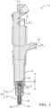
Figure 1 is an axial section of a dual fuel injector provided with a nozzle arrangement as per the invention. -
Figure 2 is an axial section of the nozzle arrangement shown infigure 1 . -
Figure 3 is an alternative arrangement of the nozzle offigure 1 . -
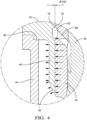
Figure 4 is a magnified detail of an anti-leakage feature provided on the nozzle of either preceding figure. - In reference to
figure 1 is described adual fuel injector 10 adapted to inject in a compression chamber of an internal combustion engine a first fuel F1, such as pressurized diesel or gasoline and, a second fuel F2 such as compressed gas. Theinjector 10 has an elongated shape extending along a main axis X, and it comprises anactuation assembly 12, not described in detail and represented on the top of the figure, that cooperates with anozzle assembly 14, on the bottom offigure 1 . Said twoassemblies capnut 16 engaged around thenozzle 14 and bearing on anannular shoulder face 18 of the nozzle and, firmly screwed on theactuation assembly 12. The arbitrary orientation of the figure is utilized simply to ease and clarify the present description. Words such as "upper, under, top, above or below..." may be used without any limiting intention. - The
injector 10 is provided with a first injection circuit enabling the first fuel F1 to flow from afirst inlet 20 arranged in the actuation assembly to a first set ofinjection holes 22 arranged at the bottom end of thenozzle assembly 14 and, with a second injection circuit for the second fuel F2 to flow from asecond inlet 24 also arranged in the actuation assembly to a second set ofinjection holes 26 arranged at the bottom end of thenozzle assembly 14. - The
nozzle assembly 14, now detailed in reference tofigures 2 ,3 and4 , comprises abody 28 having anupper member 30 and atip member 32, anouter valve member 34, aninner valve member 36, aspring 38 and aplug 40. - In a first embodiment presented on
figure 2 theshoulder face 18 on which bears thecapnut 16 is on the outer peripheral face of theupper member 30 of the body. Consequently, thetip member 32 is fixed to theupper member 30, for instance by welding. In the second embodiment presented onfigure 3 , saidshoulder face 18 is arranged on the outer face of thetip member 32 therefore, when thecapnut 16 is tightened theupper member 30 is compressed between thetip member 32 and theactuation assembly 12 and no specific fixation means is required to maintain theupper member 30 in place. In both embodiments dowels, not represented, ensure correct orientation and angular positioning of the nozzle assembly with theactuation assembly 12. - The
upper member 30 is a cylinder and it extends from a transverseupper face 42 to an underface 44 from which centrally and axially protrudes anintegral sleeve member 46 downwardly extending toward adistant extremity 48. Saidupper member 30 is also provided with an axial X throughbore 50 opening in saidupper face 42 and extending through thesleeve 46 opening in saiddistant extremity 48, either keeping throughout its length a constant diameter D50 or, having a slight taper. In case of a taper, the taper can be limited to the sleeve area or could extend throughout thebore 50 from theupper face 42 down to theextremity 48 of the sleeve. The difference in diameters between the two ends of taper area could be around 10µm, preferably less than 10µm. This taper can be oriented either direction along the axis, creating a clearance increasing or narrowing as approaching thedistant extremity 48. Furthermore, the taper can be created all along the length either of the sleeve or thecomplete bore 50 or, only on part of it, the other part being cylindrical. Such clearance can also be created with a cylindrical sleeve and a tapered outer face of theouter valve member 34. Moreover, afirst channel 52 extends in the upper member from afirst inlet 54 arranged in theupper face 42 to a first annular groove part of afirst ring groove 56 arranged, on the described embodiment substantially at equidistance between theupper face 42 and theunder face 44, to open in said throughbore 50 and also, asecond channel 58 extends from asecond inlet 60 also arranged in theupper face 42 to a second annular groove part of asecond ring groove 62 arranged proximal the underface 44 and also opening in said throughbore 50 at the level of the top end of thesleeve 46. - In the described embodiment the
sleeve member 46 has a constant radial thickness T relatively small in comparison to the axial length L measured from theunder face 44 to thedistant extremity 48. In an alternative embodiment not represented, the sleeve member have a non-constant radial thickness T slightly decreasing as approaching thedistant extremity 48 or, decreasing in steps between sections of constant thickness. A ratio of 8:1 is represented on the figures although another ratio may be chosen. Also, thesleeve member 46 is represented integral to theupper member 30 meaning it is machined within a single metal blank. In an alternative not represented, thesleeve member 46 could be a separate part fixed to theupper member 30 by welding or press-fitting, screwing or any other fixing means. Such non-integral assembly would for instance enable to choose different materials for the sleeve and the upper member. - The
tip member 32 of the body has aperipheral wall 64 axially X extending from a large topannular face 66 that complementary engages with the peripheral area of theunder face 44 of the upper member, to anarrow tip end 68. Theperipheral wall 64 cylindrically extends from saidtop face 66 forming alarge portion 70 of the tip member then, it downwardly narrows via a tapered portion to a cylindricalnarrow portion 72 extending to saidtip end 68. Theperipheral wall 64 defines an inner space S inside thetip member 32, said space S opening at thetip end 68 in an axialcylindrical bore 74 coaxial to thebore 50 arranged in theupper member 30. Right above said bottom bore 74 according to the arbitrary orientation of the figure, are arranged the injection holes of thesecond set 26, said holes extending through theperipheral wall 64 from the inner space S to the outer face of thewall 64. Adjacent to the entry of theholes 26, in the inner space S, the peripheral wall forms a small sloped face that is part to asecond valve seat 76. - As visible on the figures, the
sleeve member 46 extends in said inner space S, a portion of the space S outwardly surrounding thesleeve member 46. - The
outer valve member 34 is a hollow needle axially extending from anupper end 78 to a tipcylindrical end 80. It is axially guided in thenozzle body 28 between saidupper end 78 sliding in the throughbore 50 of theupper member 30 and saidtip end 80 sliding in the bottom bore 74 of thetip member 32. Theouter valve 34 comprises several cylindrical portions, theupper end 78 portion being the largest having substantially the axial length of theupper member 30 from theupper face 42 to thedistant extremity 48 of the sleeve and, thetip end 80 being the smallest cylindrical portion of the outer valve member, and being provided with complementary sloped face cooperating in thesecond valve seat 76. Theouter valve member 34 is also provided with an inner axial bore 82 that is sealed at theupper end 78 by theplug 40, said inner bore 82 downwardly extending to thetip end 80 where it narrows in a conical face part of afirst valve seat 84, the first set of injection holes 22 being provided right below saidfirst valve seat 84, extending from an entry arranged in a small sac arranged at the very tip of the conical face to an exit arranged on the outside face of the valve member. In the uppercylindrical portion 78, the outer valve member is provided, on its outer face with a first annular groove complementary to thefirst ring groove 56 and also with a second annular groove complementary to thesecond ring groove 62. From thefirst ring groove 56 at least oneradial channel 86, not represented, extends through the outer valve member and opens in the upper end of saidinner bore 82. Also, from thesecond ring groove 62 at least oneother channel 88, two being represented on the figures, extends through the outer valve member and opens in theinner bore 82 in a position that is substantially aligned to the underface 44 of the upper member. - The
inner valve member 36 is a plain needle axially guided in theinner bore 82 of the outer valve member and that axially extends from ahead end 90 to apointy tip end 92 that complementary cooperates with thefirst valve seat 84. Thehead end 90 of the needle comprises a malecylindrical portion 94 axially guided in an upper portion of theinner bore 82 of the outer valve member that is arranged between the opening of thechannels 86 arriving from the first ring groove and the opening of thechannels 88 arriving from the second ring groove. Above said guidedportion 94, theinner valve member 36 forms a transverse shoulder face 96 from the center of which anextension member 98 upwardly protrudes in the space that is at the very upper end of theinner bore 82, said space forming afirst control chamber 100. Thespring 38 is engaged around theextension member 98 and is axially compressed between theshoulder face 96 of the needle and theplug 40, downwardly biasing theneedle 36 toward a closed position of the first set of injection holes 22. In addition to be a guiding means, the malecylindrical portion 94 is also a cylindrical seal between thefirst control chamber 100 and theinner bore 82. - In a non-represented alternative, the
sleeve 46 has a smaller inner diameter than thebore 50 and, theouter valve member 34 has complementary diameters larger in theupper section 78 and smaller in thesleeve section 46. This different diameters embodiment helps reducing further fuel leaks between the sleeve and theouter valve member 34. - In use, the first fuel F1 and the second fuel F2 are substantially compressed to similar pressure. The
inner valve member 36 slides relative to theouter valve member 34 alternatively opening and closing the first set of injection holes 22 for injecting, or not, the first fuel F1, displacement of theinner valve member 36 being a function of the pressure differential of the first fuel F1 between thefirst control chamber 100 and thefirst valve seat 84. Also, theouter valve member 34 slides relative to thebody 28 alternatively opening and closing the second set of injection holes 26 for injecting, or not, the second fuel F2. The displacement of theouter valve member 34 is controlled dependent on the pressure of the first fuel F1 in a second control chamber, not shown, and arranged in theactuation assembly 12. - Tests have been made with first fuel F1 being diesel pressurized up to 3000 bars and second fuel F2 being compressed natural gas pressurized to a similar levels. To minimize leakage, the pressure of the first fuel F1 is preferably greater than the pressure of the second fuel F2 by about 10 bars..
- In reference to
figure 4 is explained the pressure balance around thesleeve member 46 that creates the anti-leakage means. When reaching thesecond ring groove 62 the pressurized first fuel F1 has a tendency to slightly open the functional clearance arranged between theouter valve member 34 and thebore 50 outwardly biasing and enlarging thesleeve member 46, said clearance being necessary to accommodate the sliding displacements, a small leak of said first fuel F1 engaging in said open functional clearance. To balance said influence of the first fuel F1, the second fuel F2, pressurized in the inner S of the body to a similar pressure than the first fuel F1, inwardly biases thesleeve member 46 and tends to close and minimize said functional clearance and thus preventing fuel leaks. -
- X
- main axis
- F1
- first fuel
- F2
- second fuel
- T
- thickness of the sleeve
- L
- length of the sleeve
- S
- inner space
- 10
- injector
- 12
- actuation assembly
- 14
- nozzle assembly
- 16
- capnut
- 18
- shoulder face
- 20
- first inlet
- 22
- first set of injection holes
- 24
- second inlet
- 26
- second set of injection holes
- 28
- body of the nozzle
- 30
- upper member of the body
- 32
- tip member of the nozzle
- 34
- outer valve member
- 36
- inner valve member - needle
- 38
- spring
- 40
- plug
- 42
- upper face of the upper member of the body
- 44
- under face of the upper member of the body
- 46
- sleeve - anti-leakage feature
- 48
- distant extremity of the sleeve
- 50
- bore
- 52
- first channel
- 54
- first inlet
- 56
- first ring groove
- 58
- second channel
- 60
- second inlet
- 62
- second ring groove
- 64
- peripheral wall
- 66
- annular face
- 68
- tip end of the tip member
- 70
- large portion of the tip end
- 72
- narrow portion of the tip end
- 74
- bottom bore of the body
- 76
- second valve seat
- 78
- upper cylindrical portion of the outer needle
- 80
- tip cylindrical portion of the outer needle
- 82
- axial bore inner to the outer valve
- 84
- first valve seat
- 86
- channel from the first ring groove
- 88
- channel from the second ring groove
- 90
- head end of the inner valve member
- 92
- pointy end of the inner valve member
- 94
- guided portion of the head of the inner valve member
- 96
- shoulder face
- 98
- extension member
- 100
- first control chamber
Claims (8)
- Nozzle assembly (14) of a dual fuel injector (10) of an internal combustion engine, said nozzle assembly (14) extending along a main axis (X) from a large upper end adapted to cooperate with an actuation member (12) of the injector (10) to a narrow tip end (32), said nozzle assembly (14) comprising coaxially arranged along said main axis (X) an elongated body having a peripheral wall (64) surrounding an inner space (S) which portion proximal the upper end defines an upper guiding bore (50) for axially guiding an outer valve member (34) arranged therein, said outer valve member (34) being itself provided with a axial bore (82) in which is axially guided an inner valve member (36);and wherein the nozzle assembly (14) further comprises- a first fuel F1 conduit comprising said axial bore (82) and extending from an inlet (60) arranged in the large upper end face (42) of the body to a first set of injection holes (22) arranged in the narrow tip end of the outer valve member (34) and,- a second fuel F2 conduit comprising said inner space (S) and extending from another inlet arranged in the large upper end face (42) of the body to a second set of injection holes (26) arranged in the narrow tip end of the body,so that in use, a first fuel (F1), such as pressurized diesel or gasoline, flows inside the outer valve member (34) and, a second fuel (F2), such as a compressed gas fills and flows in the inner space (S) surrounding said outer valve member,wherein the nozzle assembly (14) is further provided with an anti-leakage feature comprising a cylindrical tubular sleeve (46) axially (X) extending in said inner space (S) from an upper end attached to the body (28, 30) to a distant lower end (48), the outer valve member (34) being axially guided through said sleeve (46) and,wherein the sleeve (46) is arranged as an extension of the upper guiding bore (50) and wherein a clearance is defined between the outer valve member (34) and the bore (50), or the sleeve (46) and,wherein the inner diameter of the sleeve (46) is smaller than or identical to the inner diameter of the upper guiding bore (50) and,wherein said clearance is not constant, the sleeve (46) or the outer valve member (34) being provided on at least part of the length with a taper.
- Nozzle assembly (14) as claimed in claim 1 wherein the clearance changes by less than 10µm.
- Nozzle assembly (14) as claimed in any one of the preceding claims wherein the sleeve (46) is integral to the body.
- Nozzle assembly (14) as claimed in any one of the claims 1 or 2 wherein the sleeve (46) is a separate member non-integral and fixed to the body.
- Nozzle assembly (14) as claimed in any one of the preceding claims wherein the body (28) comprises an upper member (30) and a tip member (32), the upper guiding bore (50) being defined in the upper member (30), the tubular sleeve (46) extending from said upper member (30).
- Nozzle assembly (14) as claimed in claim 5 wherein the upper member (30) axially extends from an upper transverse face (42) wherein are defined the inlets to a transverse under face (44) complementary receiving the tip member (32), the tubular sleeve (46) extending from said transverse under face (44).
- Nozzle assembly (14) as claimed in any one of the preceding claims wherein the axial length (L) of the sleeve (46) extending in the inner space (S) is approximately eight times the radial thickness (T) of the tubular wall of the sleeve (46).
- Dual fuel injector (10) comprising a nozzle assembly (14) as set in any one of the preceding claims.
Applications Claiming Priority (2)
| Application Number | Priority Date | Filing Date | Title |
|---|---|---|---|
| GB1616132.5A GB2554368B (en) | 2016-09-22 | 2016-09-22 | Dual fuel injector nozzle with an anti-leakage feature |
| PCT/EP2017/073340 WO2018054788A1 (en) | 2016-09-22 | 2017-09-15 | Dual fuel nozzle arrangement |
Publications (2)
| Publication Number | Publication Date |
|---|---|
| EP3516193A1 EP3516193A1 (en) | 2019-07-31 |
| EP3516193B1 true EP3516193B1 (en) | 2023-10-18 |
Family
ID=57539706
Family Applications (1)
| Application Number | Title | Priority Date | Filing Date |
|---|---|---|---|
| EP17767844.8A Active EP3516193B1 (en) | 2016-09-22 | 2017-09-15 | Dual fuel nozzle arrangement |
Country Status (5)
| Country | Link |
|---|---|
| US (1) | US10883428B2 (en) |
| EP (1) | EP3516193B1 (en) |
| CN (1) | CN109715919B (en) |
| GB (1) | GB2554368B (en) |
| WO (1) | WO2018054788A1 (en) |
Family Cites Families (19)
| Publication number | Priority date | Publication date | Assignee | Title |
|---|---|---|---|---|
| CH672661A5 (en) | 1987-03-17 | 1989-12-15 | Sulzer Ag | |
| JPH07243355A (en) * | 1994-02-28 | 1995-09-19 | Mitsubishi Heavy Ind Ltd | Binary fluid injection valve |
| JPH1130164A (en) * | 1997-07-09 | 1999-02-02 | Mitsubishi Heavy Ind Ltd | Fuel injection device for internal combustion engine |
| US6073862A (en) * | 1998-09-16 | 2000-06-13 | Westport Research Inc. | Gaseous and liquid fuel injector |
| JP2006183468A (en) | 2004-12-24 | 2006-07-13 | Denso Corp | Fuel injection device |
| SE0502371L (en) * | 2005-10-27 | 2006-09-19 | Xerex Ab | Ejector with mounting sleeve, as well as mounting procedure |
| JP4811733B2 (en) * | 2007-03-22 | 2011-11-09 | スズキ株式会社 | Fuel supply control system for bi-fuel vehicles |
| US20120255523A1 (en) * | 2011-04-08 | 2012-10-11 | Caterpillar Inc. | Dual fuel injector and engine using same |
| US8726884B2 (en) * | 2011-05-19 | 2014-05-20 | Caterpillar Inc. | Quill assembly for a dual fuel common rail fuel system |
| CA2743043C (en) * | 2011-06-14 | 2012-09-18 | Westport Power Inc. | Dual fuel injection valve |
| US8978623B2 (en) * | 2011-12-23 | 2015-03-17 | Caterpillar Inc. | Dual fuel injector having fuel leak seals |
| US9506434B2 (en) * | 2012-08-29 | 2016-11-29 | Caterpillar Inc. | Dual check fuel injector with single actuator |
| CN102979654B (en) * | 2012-12-20 | 2016-06-29 | 余姚市舒春机械有限公司 | A kind of anti-carbon deposition cooling type pintle nozzle match-ing parts |
| GB201404131D0 (en) * | 2014-03-10 | 2014-04-23 | Delphi Int Operations Lux Srl | Fuel injector |
| AT516250B1 (en) * | 2015-01-07 | 2016-04-15 | Hoerbiger Kompressortech Hold | Fuel gas supply and ignition device for a gas engine |
| CA2884945C (en) * | 2015-03-13 | 2018-02-27 | Michael C. Wickstone | Hydraulically actuated gaseous fuel injector |
| DE102015208099A1 (en) * | 2015-04-30 | 2016-11-03 | Robert Bosch Gmbh | Zweistoffinjektor |
| DE102015209134A1 (en) * | 2015-05-19 | 2016-11-24 | Robert Bosch Gmbh | Zweistoffinjektor |
| CN105756825B (en) * | 2016-04-21 | 2018-01-19 | 哈尔滨工程大学 | Combined electromagnetic oil spout is pressurized piezoelectricity jet hybrid fuel jet device |
-
2016
- 2016-09-22 GB GB1616132.5A patent/GB2554368B/en active Active
-
2017
- 2017-09-15 US US16/335,980 patent/US10883428B2/en active Active
- 2017-09-15 CN CN201780058216.5A patent/CN109715919B/en active Active
- 2017-09-15 EP EP17767844.8A patent/EP3516193B1/en active Active
- 2017-09-15 WO PCT/EP2017/073340 patent/WO2018054788A1/en not_active Ceased
Also Published As
| Publication number | Publication date |
|---|---|
| US20200018246A1 (en) | 2020-01-16 |
| WO2018054788A1 (en) | 2018-03-29 |
| GB201616132D0 (en) | 2016-11-09 |
| EP3516193A1 (en) | 2019-07-31 |
| CN109715919A (en) | 2019-05-03 |
| GB2554368A (en) | 2018-04-04 |
| CN109715919B (en) | 2022-06-03 |
| GB2554368B (en) | 2020-06-03 |
| US10883428B2 (en) | 2021-01-05 |
Similar Documents
| Publication | Publication Date | Title |
|---|---|---|
| CN109611250B (en) | fuel injector | |
| US10208711B2 (en) | Gas injector including an outwardly opening valve closure element | |
| US8479711B2 (en) | Piezoelectric direct acting fuel injector with hydraulic link | |
| US10260450B2 (en) | Cylinder head | |
| EP3426958B1 (en) | Pressure regulating modules with controlled leak paths | |
| JP2015508474A (en) | Control valve | |
| US20170089312A1 (en) | Fuel Injector | |
| US10883428B2 (en) | Dual fuel nozzle arrangement | |
| US9909537B2 (en) | Gas injector having two sealing regions | |
| CN102312763B (en) | The fuel injector of explosive motor | |
| US12385456B2 (en) | Fuel-rail assembly | |
| US10495040B2 (en) | Control valve assembly | |
| EP2944798B1 (en) | Fuel injector | |
| KR101682346B1 (en) | Fuel injection nozzle for internal combustion engines | |
| US20180306152A1 (en) | Fluid-Injection Device For Internal Combustion Engines | |
| KR20070113950A (en) | Fuel Control Servo Valve And Fuel Injector With The Same | |
| WO2025012396A1 (en) | Gas injector for an internal combustion engine | |
| EP3851663A1 (en) | Valve seat body assembly for a fluid injector of an internal combustion engine with a valve seat body and an orifice part | |
| GB2526273A (en) | Fuel injector | |
| GB2567849A (en) | High pressure valve | |
| GB2124299A (en) | I.C. engine fuel injection nozzles |
Legal Events
| Date | Code | Title | Description |
|---|---|---|---|
| STAA | Information on the status of an ep patent application or granted ep patent |
Free format text: STATUS: UNKNOWN |
|
| STAA | Information on the status of an ep patent application or granted ep patent |
Free format text: STATUS: THE INTERNATIONAL PUBLICATION HAS BEEN MADE |
|
| PUAI | Public reference made under article 153(3) epc to a published international application that has entered the european phase |
Free format text: ORIGINAL CODE: 0009012 |
|
| STAA | Information on the status of an ep patent application or granted ep patent |
Free format text: STATUS: REQUEST FOR EXAMINATION WAS MADE |
|
| 17P | Request for examination filed |
Effective date: 20190423 |
|
| AK | Designated contracting states |
Kind code of ref document: A1 Designated state(s): AL AT BE BG CH CY CZ DE DK EE ES FI FR GB GR HR HU IE IS IT LI LT LU LV MC MK MT NL NO PL PT RO RS SE SI SK SM TR |
|
| AX | Request for extension of the european patent |
Extension state: BA ME |
|
| DAV | Request for validation of the european patent (deleted) | ||
| DAX | Request for extension of the european patent (deleted) | ||
| STAA | Information on the status of an ep patent application or granted ep patent |
Free format text: STATUS: EXAMINATION IS IN PROGRESS |
|
| 17Q | First examination report despatched |
Effective date: 20200930 |
|
| GRAP | Despatch of communication of intention to grant a patent |
Free format text: ORIGINAL CODE: EPIDOSNIGR1 |
|
| STAA | Information on the status of an ep patent application or granted ep patent |
Free format text: STATUS: GRANT OF PATENT IS INTENDED |
|
| INTG | Intention to grant announced |
Effective date: 20230125 |
|
| GRAJ | Information related to disapproval of communication of intention to grant by the applicant or resumption of examination proceedings by the epo deleted |
Free format text: ORIGINAL CODE: EPIDOSDIGR1 |
|
| STAA | Information on the status of an ep patent application or granted ep patent |
Free format text: STATUS: EXAMINATION IS IN PROGRESS |
|
| GRAP | Despatch of communication of intention to grant a patent |
Free format text: ORIGINAL CODE: EPIDOSNIGR1 |
|
| STAA | Information on the status of an ep patent application or granted ep patent |
Free format text: STATUS: GRANT OF PATENT IS INTENDED |
|
| INTC | Intention to grant announced (deleted) | ||
| INTG | Intention to grant announced |
Effective date: 20230504 |
|
| P01 | Opt-out of the competence of the unified patent court (upc) registered |
Effective date: 20230327 |
|
| GRAS | Grant fee paid |
Free format text: ORIGINAL CODE: EPIDOSNIGR3 |
|
| RAP3 | Party data changed (applicant data changed or rights of an application transferred) |
Owner name: DELPHI TECHNOLOGIES IP LIMITED |
|
| GRAA | (expected) grant |
Free format text: ORIGINAL CODE: 0009210 |
|
| STAA | Information on the status of an ep patent application or granted ep patent |
Free format text: STATUS: THE PATENT HAS BEEN GRANTED |
|
| AK | Designated contracting states |
Kind code of ref document: B1 Designated state(s): AL AT BE BG CH CY CZ DE DK EE ES FI FR GB GR HR HU IE IS IT LI LT LU LV MC MK MT NL NO PL PT RO RS SE SI SK SM TR |
|
| REG | Reference to a national code |
Ref country code: GB Ref legal event code: FG4D |
|
| REG | Reference to a national code |
Ref country code: CH Ref legal event code: EP |
|
| REG | Reference to a national code |
Ref country code: DE Ref legal event code: R096 Ref document number: 602017075461 Country of ref document: DE |
|
| REG | Reference to a national code |
Ref country code: IE Ref legal event code: FG4D |
|
| REG | Reference to a national code |
Ref country code: LT Ref legal event code: MG9D |
|
| REG | Reference to a national code |
Ref country code: NL Ref legal event code: MP Effective date: 20231018 |
|
| REG | Reference to a national code |
Ref country code: AT Ref legal event code: MK05 Ref document number: 1622680 Country of ref document: AT Kind code of ref document: T Effective date: 20231018 |
|
| PG25 | Lapsed in a contracting state [announced via postgrant information from national office to epo] |
Ref country code: NL Free format text: LAPSE BECAUSE OF FAILURE TO SUBMIT A TRANSLATION OF THE DESCRIPTION OR TO PAY THE FEE WITHIN THE PRESCRIBED TIME-LIMIT Effective date: 20231018 |
|
| PG25 | Lapsed in a contracting state [announced via postgrant information from national office to epo] |
Ref country code: GR Free format text: LAPSE BECAUSE OF FAILURE TO SUBMIT A TRANSLATION OF THE DESCRIPTION OR TO PAY THE FEE WITHIN THE PRESCRIBED TIME-LIMIT Effective date: 20240119 |
|
| PG25 | Lapsed in a contracting state [announced via postgrant information from national office to epo] |
Ref country code: IS Free format text: LAPSE BECAUSE OF FAILURE TO SUBMIT A TRANSLATION OF THE DESCRIPTION OR TO PAY THE FEE WITHIN THE PRESCRIBED TIME-LIMIT Effective date: 20240218 |
|
| PG25 | Lapsed in a contracting state [announced via postgrant information from national office to epo] |
Ref country code: LT Free format text: LAPSE BECAUSE OF FAILURE TO SUBMIT A TRANSLATION OF THE DESCRIPTION OR TO PAY THE FEE WITHIN THE PRESCRIBED TIME-LIMIT Effective date: 20231018 |
|
| PG25 | Lapsed in a contracting state [announced via postgrant information from national office to epo] |
Ref country code: AT Free format text: LAPSE BECAUSE OF FAILURE TO SUBMIT A TRANSLATION OF THE DESCRIPTION OR TO PAY THE FEE WITHIN THE PRESCRIBED TIME-LIMIT Effective date: 20231018 |
|
| PG25 | Lapsed in a contracting state [announced via postgrant information from national office to epo] |
Ref country code: ES Free format text: LAPSE BECAUSE OF FAILURE TO SUBMIT A TRANSLATION OF THE DESCRIPTION OR TO PAY THE FEE WITHIN THE PRESCRIBED TIME-LIMIT Effective date: 20231018 |
|
| PG25 | Lapsed in a contracting state [announced via postgrant information from national office to epo] |
Ref country code: LT Free format text: LAPSE BECAUSE OF FAILURE TO SUBMIT A TRANSLATION OF THE DESCRIPTION OR TO PAY THE FEE WITHIN THE PRESCRIBED TIME-LIMIT Effective date: 20231018 Ref country code: IS Free format text: LAPSE BECAUSE OF FAILURE TO SUBMIT A TRANSLATION OF THE DESCRIPTION OR TO PAY THE FEE WITHIN THE PRESCRIBED TIME-LIMIT Effective date: 20240218 Ref country code: GR Free format text: LAPSE BECAUSE OF FAILURE TO SUBMIT A TRANSLATION OF THE DESCRIPTION OR TO PAY THE FEE WITHIN THE PRESCRIBED TIME-LIMIT Effective date: 20240119 Ref country code: ES Free format text: LAPSE BECAUSE OF FAILURE TO SUBMIT A TRANSLATION OF THE DESCRIPTION OR TO PAY THE FEE WITHIN THE PRESCRIBED TIME-LIMIT Effective date: 20231018 Ref country code: BG Free format text: LAPSE BECAUSE OF FAILURE TO SUBMIT A TRANSLATION OF THE DESCRIPTION OR TO PAY THE FEE WITHIN THE PRESCRIBED TIME-LIMIT Effective date: 20240118 Ref country code: AT Free format text: LAPSE BECAUSE OF FAILURE TO SUBMIT A TRANSLATION OF THE DESCRIPTION OR TO PAY THE FEE WITHIN THE PRESCRIBED TIME-LIMIT Effective date: 20231018 Ref country code: PT Free format text: LAPSE BECAUSE OF FAILURE TO SUBMIT A TRANSLATION OF THE DESCRIPTION OR TO PAY THE FEE WITHIN THE PRESCRIBED TIME-LIMIT Effective date: 20240219 |
|
| PG25 | Lapsed in a contracting state [announced via postgrant information from national office to epo] |
Ref country code: SE Free format text: LAPSE BECAUSE OF FAILURE TO SUBMIT A TRANSLATION OF THE DESCRIPTION OR TO PAY THE FEE WITHIN THE PRESCRIBED TIME-LIMIT Effective date: 20231018 Ref country code: RS Free format text: LAPSE BECAUSE OF FAILURE TO SUBMIT A TRANSLATION OF THE DESCRIPTION OR TO PAY THE FEE WITHIN THE PRESCRIBED TIME-LIMIT Effective date: 20231018 Ref country code: PL Free format text: LAPSE BECAUSE OF FAILURE TO SUBMIT A TRANSLATION OF THE DESCRIPTION OR TO PAY THE FEE WITHIN THE PRESCRIBED TIME-LIMIT Effective date: 20231018 Ref country code: NO Free format text: LAPSE BECAUSE OF FAILURE TO SUBMIT A TRANSLATION OF THE DESCRIPTION OR TO PAY THE FEE WITHIN THE PRESCRIBED TIME-LIMIT Effective date: 20240118 Ref country code: LV Free format text: LAPSE BECAUSE OF FAILURE TO SUBMIT A TRANSLATION OF THE DESCRIPTION OR TO PAY THE FEE WITHIN THE PRESCRIBED TIME-LIMIT Effective date: 20231018 Ref country code: HR Free format text: LAPSE BECAUSE OF FAILURE TO SUBMIT A TRANSLATION OF THE DESCRIPTION OR TO PAY THE FEE WITHIN THE PRESCRIBED TIME-LIMIT Effective date: 20231018 |
|
| RAP2 | Party data changed (patent owner data changed or rights of a patent transferred) |
Owner name: PHINIA DELPHI LUXEMBOURG SARL |
|
| PG25 | Lapsed in a contracting state [announced via postgrant information from national office to epo] |
Ref country code: DK Free format text: LAPSE BECAUSE OF FAILURE TO SUBMIT A TRANSLATION OF THE DESCRIPTION OR TO PAY THE FEE WITHIN THE PRESCRIBED TIME-LIMIT Effective date: 20231018 |
|
| REG | Reference to a national code |
Ref country code: DE Ref legal event code: R097 Ref document number: 602017075461 Country of ref document: DE |
|
| PG25 | Lapsed in a contracting state [announced via postgrant information from national office to epo] |
Ref country code: CZ Free format text: LAPSE BECAUSE OF FAILURE TO SUBMIT A TRANSLATION OF THE DESCRIPTION OR TO PAY THE FEE WITHIN THE PRESCRIBED TIME-LIMIT Effective date: 20231018 |
|
| PG25 | Lapsed in a contracting state [announced via postgrant information from national office to epo] |
Ref country code: SK Free format text: LAPSE BECAUSE OF FAILURE TO SUBMIT A TRANSLATION OF THE DESCRIPTION OR TO PAY THE FEE WITHIN THE PRESCRIBED TIME-LIMIT Effective date: 20231018 |
|
| PG25 | Lapsed in a contracting state [announced via postgrant information from national office to epo] |
Ref country code: SM Free format text: LAPSE BECAUSE OF FAILURE TO SUBMIT A TRANSLATION OF THE DESCRIPTION OR TO PAY THE FEE WITHIN THE PRESCRIBED TIME-LIMIT Effective date: 20231018 Ref country code: SK Free format text: LAPSE BECAUSE OF FAILURE TO SUBMIT A TRANSLATION OF THE DESCRIPTION OR TO PAY THE FEE WITHIN THE PRESCRIBED TIME-LIMIT Effective date: 20231018 Ref country code: RO Free format text: LAPSE BECAUSE OF FAILURE TO SUBMIT A TRANSLATION OF THE DESCRIPTION OR TO PAY THE FEE WITHIN THE PRESCRIBED TIME-LIMIT Effective date: 20231018 Ref country code: IT Free format text: LAPSE BECAUSE OF FAILURE TO SUBMIT A TRANSLATION OF THE DESCRIPTION OR TO PAY THE FEE WITHIN THE PRESCRIBED TIME-LIMIT Effective date: 20231018 Ref country code: EE Free format text: LAPSE BECAUSE OF FAILURE TO SUBMIT A TRANSLATION OF THE DESCRIPTION OR TO PAY THE FEE WITHIN THE PRESCRIBED TIME-LIMIT Effective date: 20231018 Ref country code: DK Free format text: LAPSE BECAUSE OF FAILURE TO SUBMIT A TRANSLATION OF THE DESCRIPTION OR TO PAY THE FEE WITHIN THE PRESCRIBED TIME-LIMIT Effective date: 20231018 Ref country code: CZ Free format text: LAPSE BECAUSE OF FAILURE TO SUBMIT A TRANSLATION OF THE DESCRIPTION OR TO PAY THE FEE WITHIN THE PRESCRIBED TIME-LIMIT Effective date: 20231018 |
|
| PLBE | No opposition filed within time limit |
Free format text: ORIGINAL CODE: 0009261 |
|
| STAA | Information on the status of an ep patent application or granted ep patent |
Free format text: STATUS: NO OPPOSITION FILED WITHIN TIME LIMIT |
|
| 26N | No opposition filed |
Effective date: 20240719 |
|
| REG | Reference to a national code |
Ref country code: GB Ref legal event code: 732E Free format text: REGISTERED BETWEEN 20240919 AND 20240925 |
|
| PG25 | Lapsed in a contracting state [announced via postgrant information from national office to epo] |
Ref country code: SI Free format text: LAPSE BECAUSE OF FAILURE TO SUBMIT A TRANSLATION OF THE DESCRIPTION OR TO PAY THE FEE WITHIN THE PRESCRIBED TIME-LIMIT Effective date: 20231018 |
|
| PG25 | Lapsed in a contracting state [announced via postgrant information from national office to epo] |
Ref country code: SI Free format text: LAPSE BECAUSE OF FAILURE TO SUBMIT A TRANSLATION OF THE DESCRIPTION OR TO PAY THE FEE WITHIN THE PRESCRIBED TIME-LIMIT Effective date: 20231018 |
|
| PG25 | Lapsed in a contracting state [announced via postgrant information from national office to epo] |
Ref country code: MC Free format text: LAPSE BECAUSE OF FAILURE TO SUBMIT A TRANSLATION OF THE DESCRIPTION OR TO PAY THE FEE WITHIN THE PRESCRIBED TIME-LIMIT Effective date: 20231018 |
|
| REG | Reference to a national code |
Ref country code: CH Ref legal event code: PL |
|
| PG25 | Lapsed in a contracting state [announced via postgrant information from national office to epo] |
Ref country code: LU Free format text: LAPSE BECAUSE OF NON-PAYMENT OF DUE FEES Effective date: 20240915 |
|
| REG | Reference to a national code |
Ref country code: BE Ref legal event code: MM Effective date: 20240930 |
|
| PG25 | Lapsed in a contracting state [announced via postgrant information from national office to epo] |
Ref country code: BE Free format text: LAPSE BECAUSE OF NON-PAYMENT OF DUE FEES Effective date: 20240930 |
|
| PG25 | Lapsed in a contracting state [announced via postgrant information from national office to epo] |
Ref country code: CH Free format text: LAPSE BECAUSE OF NON-PAYMENT OF DUE FEES Effective date: 20240930 |
|
| PG25 | Lapsed in a contracting state [announced via postgrant information from national office to epo] |
Ref country code: IE Free format text: LAPSE BECAUSE OF NON-PAYMENT OF DUE FEES Effective date: 20240915 |
|
| PG25 | Lapsed in a contracting state [announced via postgrant information from national office to epo] |
Ref country code: FI Free format text: LAPSE BECAUSE OF FAILURE TO SUBMIT A TRANSLATION OF THE DESCRIPTION OR TO PAY THE FEE WITHIN THE PRESCRIBED TIME-LIMIT Effective date: 20231019 |
|
| PGFP | Annual fee paid to national office [announced via postgrant information from national office to epo] |
Ref country code: DE Payment date: 20250808 Year of fee payment: 9 |
|
| PGFP | Annual fee paid to national office [announced via postgrant information from national office to epo] |
Ref country code: GB Payment date: 20250814 Year of fee payment: 9 |
|
| PGFP | Annual fee paid to national office [announced via postgrant information from national office to epo] |
Ref country code: FR Payment date: 20250808 Year of fee payment: 9 |
|
| PG25 | Lapsed in a contracting state [announced via postgrant information from national office to epo] |
Ref country code: CY Free format text: LAPSE BECAUSE OF FAILURE TO SUBMIT A TRANSLATION OF THE DESCRIPTION OR TO PAY THE FEE WITHIN THE PRESCRIBED TIME-LIMIT; INVALID AB INITIO Effective date: 20170915 |
|
| PG25 | Lapsed in a contracting state [announced via postgrant information from national office to epo] |
Ref country code: HU Free format text: LAPSE BECAUSE OF FAILURE TO SUBMIT A TRANSLATION OF THE DESCRIPTION OR TO PAY THE FEE WITHIN THE PRESCRIBED TIME-LIMIT; INVALID AB INITIO Effective date: 20170915 |