EP3515806B1 - Back pack cinch - Google Patents
Back pack cinch Download PDFInfo
- Publication number
- EP3515806B1 EP3515806B1 EP17853785.8A EP17853785A EP3515806B1 EP 3515806 B1 EP3515806 B1 EP 3515806B1 EP 17853785 A EP17853785 A EP 17853785A EP 3515806 B1 EP3515806 B1 EP 3515806B1
- Authority
- EP
- European Patent Office
- Prior art keywords
- buckle
- mounting structure
- tank
- recess
- strap
- Prior art date
- Legal status (The legal status is an assumption and is not a legal conclusion. Google has not performed a legal analysis and makes no representation as to the accuracy of the status listed.)
- Active
Links
Images


Classifications
-
- B—PERFORMING OPERATIONS; TRANSPORTING
- B63—SHIPS OR OTHER WATERBORNE VESSELS; RELATED EQUIPMENT
- B63C—LAUNCHING, HAULING-OUT, OR DRY-DOCKING OF VESSELS; LIFE-SAVING IN WATER; EQUIPMENT FOR DWELLING OR WORKING UNDER WATER; MEANS FOR SALVAGING OR SEARCHING FOR UNDERWATER OBJECTS
- B63C11/00—Equipment for dwelling or working underwater; Means for searching for underwater objects
- B63C11/02—Divers' equipment
- B63C11/18—Air supply
- B63C11/22—Air supply carried by diver
-
- A—HUMAN NECESSITIES
- A45—HAND OR TRAVELLING ARTICLES
- A45F—TRAVELLING OR CAMP EQUIPMENT: SACKS OR PACKS CARRIED ON THE BODY
- A45F3/00—Travelling or camp articles; Sacks or packs carried on the body
- A45F3/10—Pack-frames carried on the body
-
- A—HUMAN NECESSITIES
- A62—LIFE-SAVING; FIRE-FIGHTING
- A62B—DEVICES, APPARATUS OR METHODS FOR LIFE-SAVING
- A62B25/00—Devices for storing or holding or carrying respiratory or breathing apparatus
-
- B—PERFORMING OPERATIONS; TRANSPORTING
- B63—SHIPS OR OTHER WATERBORNE VESSELS; RELATED EQUIPMENT
- B63C—LAUNCHING, HAULING-OUT, OR DRY-DOCKING OF VESSELS; LIFE-SAVING IN WATER; EQUIPMENT FOR DWELLING OR WORKING UNDER WATER; MEANS FOR SALVAGING OR SEARCHING FOR UNDERWATER OBJECTS
- B63C11/00—Equipment for dwelling or working underwater; Means for searching for underwater objects
- B63C11/02—Divers' equipment
- B63C11/18—Air supply
- B63C11/22—Air supply carried by diver
- B63C2011/2281—Devices for securing breathing gas tanks to diving harnesses, or back pieces of diving jackets, e.g. straps; Tensioning devices therefor
Definitions
- This invention generally relates to a back pack for an underwater breathing gas tank.
- a back pack for underwater diving generally is worn by a diver to secure the diver to his underwater breathing gas tank (hereinafter, "gas tank").
- gas tank The diver's back is on one side of the backpack and a gas tank is on the other side of the back pack.
- the back pack may have a strap that joins the gas tank to the back pack for a diver's use during diving.
- the strap length as it surrounds the gas tank is generally lessened to tighten the gas tank connection to the back pack.
- the length of the strap is generally fixed by a device such as a cinch that is hereinafter referred to interchangeably as a buckle.
- the buckle generally permits the length of the strap to be adjusted as desired for a tight fit during the dive and thereafter a loose fit such that the gas tank may be replaced.
- U.S. Patent No. 5,567,084 where a buckle is shown located on the side of the gas tank farthest away from a diver's back.
- the buckle is left unprotected on the surface of the its gas tank such that any structure that the diver may inadvertently hit or any object, including another diver may hit the buckle on the exposed surface where it is located.
- Japanese Patent Publication JPH0225389U shows a buckle located on the side of the back pack which faces the diver's back.
- the invention has the object to provide a back pack that offers greater protection than heretofore known for a back pack that includes a buckle that secures the backpack to the gas tank.
- the object is solved by an inventive back pack as defined in one of the claims 1 to 8.
- the invention provides a back pack for an underwater breathing gas tank comprising a tank mounting structure.
- the tank mounting structure has a front surface facing away from an underwater breathing gas tank when an underwater breathing gas tank is operably mounted to the tank mounting structure.
- the tank mounting structure defines a recess.
- the front surface of the tank mounting structure defines an opening of the recess.
- the tank mounting structure also defines a bottom surface of the recess opposite the opening in the front surface.
- the back pack further comprises a strap and a buckle.
- the buckle has a latched state for securing the strap in a fixed position for securing a underwater breathing gas tank to the tank mounting structure.
- the buckle when in a latched state, is positioned at least partially within the recess.
- the buckle may be pivotably attached to the tank mounting structure for rotation about a first rotational axis.
- the buckle may be an over-center mechanism such that in the latched state, the strap generates a torque on the latch in a first direction around the rotational axis biasing the latch toward the latched state and, in the unlatched state, any torque generated by the strap biases the buckle in an opposite second direction around the rotational axis toward the unlatched state.
- the buckle remains in a latched state without an additional locking mechanism.
- the tank mounting structure includes a first mounting plate that defines, at least in part, the recess.
- the tank mounting structure also includes a second mounting plate that defines at least in part, the bottom of the recess opposite the opening in the front surface.
- the second mounting plate may be located between the first mounting plate and a gas tank when a gas tank is mounted to the tank mounting structure.
- a dive bladder may be fixed between the first mounting plate and the second mounting plate.
- the strap may extend around at least a portion of the gas tank when operably mounted to the tank mounting structure.
- the strap has a first end and a second end. The first end is attached to the buckle and the second end is adjustable relative to the buckle to fix a length of the buckle when the buckle is in the latched state such that underwater breathing gas tanks of different sizes can be secured to the tank mounting structure.
- the buckle in the latched state, is between the front surface of the tank mounting structure a diver's back when a gas tank is operably connected to the tank mounting structure and a diver.
- the buckle in the latched state, is in the recess and does not extend out of the opening. In transition between the unlatched state and the latched state, a handle portion of the buckle extends out of the opening beyond the front surface.
- the opening of the recess in the tank mounting structure includes a portion that extends into a side of the tank mounting structure as well as the front surface.
- a handle portion of the buckle extends into the portion of the recess that extends into the side of the tank mounting structure when the buckle is in the unlatched state.
- the tank mounting structure defines an outer periphery and the handle extends out of the outer periphery defined by the tank mounting structure in the unlatched state and is at least partially within the outer periphery in the latched state.
- the buckle in the latched state is positioned within the recess between the bottom surface and the opening in the front surface.
- the buckle is an over center buckle.
- the tank mounting structure defines an outer periphery.
- the handle portion may be positioned at least partially within the outer periphery defined by the tank mounting structure when the buckle is in the latched state.
- the handle may extend out of the recess and the outer periphery when the buckle is in the unlatched state.
- the handle portion is positioned entirely within the outer periphery defined by the tank mounting structure when the buck is in the latched state.
- the tank mounting structure includes a first mounting plate and a second mounting plate.
- the first mounting plate includes a top portion, a middle portion, and a bottom portion.
- the top and bottom portions may each have a mounting aperture for mounting a second mounting plate.
- the top portion of the first mounting plate comprises a top concave portion of the front face of the tank mounting structure.
- the top portion may comprise a carrying handle.
- the carrying handle extends away from an underwater breathing gas tank when a gas tank is operably mounted to the tank mounting structure.
- the middle portion includes the recess and defines a first side wall and a second side wall of the recess.
- the bottom portion defines a bottom concave portion of the front surface of the tank mounting structure.
- the bottom portion has opposed wings extending away from a gas tank when operably coupled to the tank mounting structure.
- the first mounting plate includes a handle and the back pack is transportable via the handle.
- the second mounting plate includes a top, middle and bottom portion.
- the middle portion defines channel having a top wall, a bottom wall and a portion of the bottom of the recess.
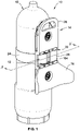
- FIG. 1 illustrates a back pack 10 for an underwater breathing gas tank 12.
- the back pack 10 includes a tank mounting structure 14 having a front surface 16 that faces away from an underwater breathing gas tank 12 when the underwater breathing gas tank 12 is operably mounted to the tank mounting structure 14.
- the front surface 16 faces towards a diver's back (not illustrated) when the back pack 10 is operably coupled to a diver for diving operations.
- the tank mounting structure 14 defines a recess 18.
- the front surface 16 of the tank mounting structure 14 defines an opening 20 of the recess 18.
- the tank mounting structure 14 defines a bottom surface 22 ( FIG. 2 ) of the recess 18.
- the bottom surface 22 of the recess 18 is opposite the opening 20 in the front surface 16.
- the back pack further includes a strap 24 and a buckle 26.
- the strap 24 and buckle 26 cooperate, as will be discussed in greater detail below, to permit the length of the strap 24 to be infinitely adjusted (as opposed to straps that are pre-configured for fixed/discrete lengths) as its surrounds an underwater breathing gas tank 12 to secure the underwater breathing gas tank 12 to the back pack 10.
- the infinite adjustability provided by the buckle 26 and strap 24 advantageously allow for varying diameters of underwater breathing gas tanks to be couple to the back pack 10.
- the buckle 26 of the back pack 10 has a latched state ( FIG. 1 ) and an unlatched state ( FIG. 5 ) to permit adjustment of the length of the strap 24.
- the buckle 26 fixes the length of the strap 24 surrounding the tank mounting structure 14 and underwater breathing gas tank 10 so as to tightly secure an underwater breathing gas tank 12 to the tank mounting structure 14.
- the strap 24 in the latched state cannot move unless the buckle 26 is unlatched to allow the strap 24 to be adjusted.
- the buckle 26 in the latched state may be positioned within the recess 18 between the bottom surface 22 of the recess 18 and the opening 20 defined by the front surface 16.
- the opening 20 of the recess 18 in the tank mounting structure 14 includes a portion that extends into a side 19, 21 of the tank mounting structure 14 as well as the front surface 16.
- the buckle 26, in the latched state is in the recess 18 between an underwater breathing gas tank 12 and a diver's back when the underwater breathing gas tank 12 is operably connected to the tank mounting structure 14 and a diver.
- the buckle 26 may be in the recess 18 and does not extend out of the opening 20 either through the sides 19, 21 or front surface 16.
- the buckle 26 in the latched state is positioned partially within the recess 18 and may extend at least partially beyond any one or more of the opening 20, front surface 16, and sides 19, 21. In such embodiments, the buckle 26 is still advantageously positioned between the bottom surface 22 and a diver's back when the back pack 10 is operably worn on a diver's back.
- the tank mounting structure 14 defines an outer periphery 28 of the tank mounting structure 14.
- a handle 104 of the buckle 26 does not extend out of, that is beyond, the outer periphery 28 defined by the tank mounting structure 14.
- the handle in the latched state is completely positioned within the outer periphery 28 of the tank mounting structure 14 to prevent it from becoming inadvertently unlatched.
- the handle 104 extends out, that is beyond the outer periphery 28 defined by the tank mounting structure 14 and in the unlatched state the handle 104 is partially located outside the recess 18.
- the latched buckle 26 located entirely inside the recess 18 provides an advantage for a diver utilizing the back pack 10 for securing an underwater breathing gas tank 12 to the tank mounting structure 14.
- a diver's back faces the front surface 16 of the tank mounting structure 14.
- the diver's back advantageously acts as a protective cover over the recess 18 concealing the buckle 26 within it.
- the bottom surface 22 of the recess 18 protects the opposite side of the buckle 26 within the recess 18 from hitting structure or being hit by objects during a dive. In this way, the buckle 26 is protected within the recess 18 from being inadvertently hit or bumped by an object or structure that would cause the buckle 26 to come unlatched and separate the underwater breathing tank 12 from the back pack 10.
- the tank mounting structure 14 may include a first mounting plate 30 that defines, at least in part, the recess 18 and a second mounting plate 32.
- the first mounting plate 30 has a top portion 34, a middle portion 36, and a bottom portion 38.
- the top portion 34 has a top mounting aperture 40.
- the bottom portion 38 has a bottom mounting aperture 42.
- the mounting apertures 40, 42 are for securing the first mounting plates to the second mounting plate 32.
- the tank mounting structure 14 may be made of a single mounting plate.
- the structures and contours, such as recess 18 and handle 28 maybe made in certain embodiments on either one of the plates or in embodiments that comprise only a single mounting plate for the tank mounting structure.
- the top portion 34 of the first mounting plate 30 further includes a top concave portion 44 of the front face 16 of the tank mounting structure 14 and a carrying handle 46.
- the carrying handle 46 is canted such that it extends away from a gas tank 12 when the underwater breathing gas tank 12 is operably mounted to the tank mounting structure 14.
- the handle 46 includes a handle aperture 48 that extends through the front surface 16 and a back surface 50 of the first mounting plate 30.
- the back pack 10 can be advantageously transported via the handle 46 built into the first mounting plate 30.
- the handle 46 may be built into or carried by the second mounting plate 32 and in yet other embodiments where the tank mounting structure 14 is a single mounting plate, the handle 46 may be built into or carried by the single mounting plate.
- the handle 46 does not interfere with either the underwater breathing gas tank 12 or the diver during a dive because of its advantageous extension away from the underwater breathing gas tank 12 while at the same time allowing tight contact between the back pack 10, the diver and an underwater breathing gas tank 12.
- the top portion 34 of the tank mounting structure 14 extends longitudinally between the outermost periphery 28 at the carrying handle 46 and an upper edge 52 of the opening 20 of the recess 18 in the front surface 16.
- the middle portion 36 of the first mounting plate 30 extends longitudinally between the upper edge 52 and a bottom edge 54 of the opening 20 of the recess 18 in the front surface 16.
- the middle portion 36 includes the recess 18 and a first side wall 56 and a second sidewall 58 of the recess 18.
- the sidewalls 56, 58 are in opposed space relation.
- the bottom portion 38 of the first mounting plate 30 extends longitudinally between the bottom edge 54 of the opening of the recess 18 and a bottom 118 of the first mounting plate 30.
- the bottom portion 38 defines a bottom concave portion 62 of the front surface 16 of the tank mounting structure 14.
- the bottom portion 38 further includes opposed wings 64 that extend away from an underwater breathing gas tank 12 when operably coupled to the tank mounting structure 14.
- the opposed wings 64 advantageously provide for a tight fit between the back pack 10 and a diver.
- the advantageous contour of the wings 64 together with the bottom concave portion 62 conform to the contour of the diver's back to provide for the comfortable and tight fit.
- the tank mounting portion 14 also includes the second mounting plate 32.
- the second mounting plate 32 defines, at least in part, the bottom surface 22 of the recess 18 opposite the opening 20 in the front surface 16.
- the second mounting plate 32 is located between the first mounting plate 30 and the underwater breathing gas tank 12 when the underwater breathing gas tank 12 is mounted to the tank mounting structure 14.
- the second mounting plate 32 includes a top portion 64, middle portion 66 and bottom portion 68 that are designed to mount to top portion 34, the middle portion 36, and the bottom portion 38 of the first mounting plate, respectively.
- the top portion 64 includes a top apertured mounting boss 70.
- the top 64 further includes top male mounting members 72 in spaced relation.
- the top portion 64 further includes a convex front surface 74.
- the middle portion 66 of the second mounting plate 32 defines u shaped channel 76 having an upper wall 78, a lower wall 80 and a bottom wall 82.
- the bottom wall 82 includes the bottom surface 22 of the recess 18 and extends between the upper and lower walls 76, 78.
- a u shaped channel is illustrated, it may be readily appreciated that the channel may take other shapes provided that the buckle 26 is permitted to remain at least partially between bottom surface 22 of the recess and the diver's back when an underwater breathing gas tank 12 is operably connected to the tank mounting structure 14 and a diver.
- the bottom portion 68 of the second mounting plate 32 includes a bottom apertured mounting boss aperture 84 and bottom male mounting members 86 in opposed space relation.
- the bottom portion 68 further includes a bottom convex front surface 88.
- Buckle 26 of the back pack 10 includes an upper arm member 90 and a lower arm member 92 that are spaced apart from one another.
- the arm members 90, 92 are generally parallel and mirror symmetric to one another and as such the lower arm 92 will be described as the upper arm 90 mirrors the lower arm 92.
- the lower arm member 92 has at a first end 94, a first aperture 96, a second aperture 98 and a third aperture 100.
- a bottom mounting pin 102 passes through the first aperture 96 and into the lower wall 80 to pivotally connect the buckle 26 to the second mounting plate 32.
- a top mounting pin 103 passes through an aperture in the upper arm 90 and into the upper wall 78 to pivotally connect the buckle 26 to the second mounting plate 32.
- the bottom mounting pin 102 and the top mounting pin 103 define an axis of rotation 124 (see FIG. 5 ) about which the buckle 26 may pivot to provide the over the center function to secure the strap 24 in moving from the unlatched state ( FIG. 5 ) to the latched state ( FIG. 6 ).
- buckle 26 remains closed, that is, remains in a latched state by itself with no additional locking mechanism necessary.
- a cinch in the form of buckle 26 is discussed with respect to the illustrated embodiment, it may be readily appreciated the cinch is not limited to embodiments of buckle 26. Other embodiments with varying structures for the cinch may be utilized to provide the over center function.
- the buckle 26 is manipulated by a diver between its latched state and unlatched state via the buckle handle 104 located at a second end 106 of the buckle 26 opposite the first end 94.
- the buckle handle 104 has a generally rectangular buckle face 108.
- Buckle handle 104 connects upper arm member 90 and lower arm member 92. Further, connection between the upper arm member 90 and lower arm member is provided by a first buckle pin 110 having a first end that is fixed in the second aperture 98 of the lower member 92 and a second end that is fixed in the corresponding aperture of the upper arm member 90.
- a second buckle pin 112 has a first end that pass into the third aperture 100 of the lower arm member 92 and a second end that is fixed in the corresponding aperture of the upper arm member 90.
- Buckle pins 110, 112 may be press fit into the apertures, welded or soldered so as to connect the upper 90 and lower 92 arm members via buckle pins 110, 112. In yet other embodiments, the buckle pins 110, 112 may pass through the buckle 26 through either or both of upper 90 and lower 92 members to connect to tank mounting structure 14. In the embodiment illustrated, buckle pins 110 and 112 permit the strap 24 to change direction as it passes through the buckle 26 so as to create the necessary torque and friction to allow the over the center function of the buckle 26 to fix the length of the strap 24.
- recess pins 114 and 116 assist in the over the center function of the buckle 26.
- Recess pins 114, 116 do not pass through the buckle 26 but do traverse and thereby connect upper wall 78 of the second mounting plate 32 with lower wall 80 of the recess 18 to create a pathway through which strap 24 may pass.
- Strap 24 has a first end 120 that wraps around and may pivotally attach to recess pin 116 while a second end 122 of the strap 24 is free to pass around the underwater breathing gas tank 12 and then back into the recess 18 and through buckle 26 to fix the length of the strap 24 so as to tightly hold the back pack 10 to the underwater breathing gas tank 12.
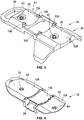
- the back surface 50 of the first mounting plate 30 is illustrated.
- the top mounting aperture 40 and bottom aperture 42 traverse the front surface 16 and back surface 50 as does the handle aperture 48.
- the back surface 50 of the top portion 34 of the first mounting plate 30 also defines a top back concave surface 126.
- the back surface 50 of the bottom portion 38 of the first mounting plate 30 also defines a bottom back concave surface 128.
- the back concave surfaces 126, 128 are, respectively, complimentary to the top convex front surface 74 of the top portion 64 of the second mounting plate 32 and the bottom convex front surface 88.
- the back concave surfaces 126, 128 are advantageously contoured to compliment and mate with, respectively, the top convex surface 74 and bottom convex surface 88 of the second mounting plate 32 when joined to the first mounting plate 30.
- the back surface 50 of the first mounting plate 30 also includes a pair of back top portion receiving apertures 130 and back bottom portion receiving apertures 132.
- the receiving apertures 130, 132 are complimentary to and receive, respectfully top male mounting members 72 and bottom male mounting members 86 to provide a press fit there between when the first mounting plate 30 and second mounting plate 32 are joined. So too, it can be readily appreciated that the top and bottom apertured mounting bosses 70 and 84 mate with and are received into, respectively, the top and bottom mounting apertures 40, 42.
- the back surface 60 of the second mounting plate 32 is illustrated.
- the back surface 60 includes concave back top surface 134, the concave back bottom wall surface 136 and concave back bottom surface 138.
- the apertures of the top and bottom apertured mounting bosses 70, 84 extend, respectively through the concave back top and bottom surfaces 134, 138.
- the concave back surfaces 134, 136, 138 advantageously conform with the convex surface of the underwater breathing gas tank 12 to provide a tight fit when joined together during diving operations.
- Concave back bottom wall surface 136 advantageously protects in part the buckle 26 in its latched state in recess 18 such that buckle 26 cannot be hit by an obstacle or structure during a dive.
- first mounting plate 30 and second mounting plate 32 may be releasably connected.
- the convex surfaces 74, 88 of the second mounting plate 32 are complimentary to the concave surfaces 126,128 of the first mounting plate 30 and cooperate in their contoured fit to assist in joining with strength the first and second mounting plates 30, 32.
- the male mounting members 72, 74 insert, respectively, into receiving apertures 130, 132 to provide a press fit between the first and second mounting plates 30, 32.
- the top and bottom apertured mounting bosses 70, 84 of the second mounting plate 32 are received into the top and bottom mounting apertures 40 and 42 of first mounting plate 30 when the first and second mounting plates 30, 32 are joined.
- first and second mounting plates 30, 32 may be completed with fasteners 140 that are inserted through the top and bottom apertured mounting bosses 70, 84 as well as the top and bottom mounting apertures 40, 42 of first mounting plate 30.
- a nut 142 attaches to each fastener 140 within the respective top and bottom mounting aperture 40, 42.
- the first and second mounting plates 30, 32 are drawn together for a tight fit and the nuts 142 rest inside their respective top and bottom mounting apertures 40, 42 such that they do not extend beyond, protrude past, or interrupt the front surface 16.
- the upper wall 78 and lower wall 80 pass into the opening in the recess 18 to define together with sidewalls 56,58 the channel 76 of the recess 18 in which the buckle 26 resides in its latched state.
- FIGS. 5 and 6 illustrate the cross section of the buckle 26 and the strap 24 through recess 18 about line 5-5 of FIG. 1 .
- FIG. 5 illustrates the buckle 26 in the latched state and
- FIG. 6 illustrates the buck in the latched state.
- fixed end 120 of strap 24 is attached to recess pin 116 such that it may pivot about recess pin 116.
- the strap 24 extends through a first gap 146 in the recess 18 between side wall 58 of the recess 18 and an edge 83 of bottom wall 82 as it is wrapped counter clockwise in the illustrated figures around an underwater breathing gas 12 for diving operations. Clockwise and counterclockwise are used simply for illustrative purposes with respect to the drawings.
- the strap 24 is wrapped counter clockwise around buckle pin 112 and inserted between buckle pins 112 and 110 such that strap 24 wraps clock wise around buckle pin 110. Strap 24 then passes clockwise around recess pin 118 and passes between recess pin 118 and recess pin 116. Free end 122 of strap 24 is then wrapped counterclockwise around buckle pin 116 with the buckle 26.
- unlatched state of the buckle 26 it is meant that the strap 24 is adjustable such that it may be tightened or loosened by decreasing or increasing its length as it surrounds an underwater breathing gas tank 12.
- buckle handle 104 is located at least partially outside the recess 18 such that the buckle front face 108 is facing toward the underwater breathing gas tank 12 while the buckle back face 107 faces away from the underwater breathing gas tank 12 and towards a diver's back when the underwater breathing gas tank 12 is placed in a position to be operably coupled to the tank mounting structure 14.
- the outermost periphery of the buckle at the second end 106 is outside of the recess 18 extending laterally beyond side wall 56 such that buckle front and back faces 106, 107 are generally parallel to the bottom surface 22 of the recess 18.
- a portion of the handle 104 of the buckle 26 extends into a portion of the recess 18 that extends into the side 19, 21 of the tank mounting structure 14 when the buckle 26 is in the unlatched state. This provides a visual indication to the diver that the buckle 26 is unlatched. It also allows the diver to easily grip and apply force to the buckle 26 to transition it into the latched state.
- the length of the strap 26 is adjusted by pulling on the free end 122 of the strap 24 to move the strap in a generally counterclockwise manner to tighten and thus shorten the length of the strap 24 length as it surrounds an underwater breathing gas tank 12.
- the length of the strap 24 as it surrounds the underwater breathing gas tank 12 may be increased, that is loosened in the open state of the buckle 26 by pulling on any part of the strap 24 away from the fixed end 120 to move the strap 24 in a generally clockwise direction.
- Strap 24 may also have pre-configured visible lines (not illustrated) along its length for alignment with the tank mounting structure 14, buckle 26 or the strap 24 or all to advantageously provide a visible reference for adjusting the length of the strap 24 to tightly fit around varying predetermined circumferences of underwater breathing gas tank as they are operably coupled to the tank mounting structure 14.
- bottom mounting pin 102 which together with top mounting pin 104 (not illustrated in FIG. 6 ) defines the rotation axis 124 about which buckle 26 rotates as it passes between the unlatched state of the buckle 26 (which may also be interchangeably referred to as the open state of the buckle 26) and the latched state of the buckle 26 (which may also be interchangeably referred to as the closed state of the buckle 26).
- Buckle 26 is manipulated to rotate in a counterclockwise rotation about rotation axis 124 to transition from the unlatched state to the latched state. In transition, at least a portion of the handle 104 extends out of the opening 20 of the recess 18 beyond the front surface 16.
- the buckle 26 is an over center mechanism such that in the latched state, the strap 24 creates a force 156 that is directed to generate a latching torque 158 in a first angular direction on the buckle 26 around the rotational axis 124 biasing the buckle 26 toward the latched state and maintaining the buckle in the latched state. In the latched state, the force 156 generated by the strap 24 on the buckle 26 lies on a first side 160 of rotational axis 124.
- the strap 24 creates a force 162 that generates a torque 164 on the buckle 26, in a direction opposite torque 158, around the rotational axis 124 biasing the buckle 26 toward the unlatched state.
- the force 162 acts on an opposite second side 166 of rotational axis 124 as force 156.
- the buckle 26 when the buckle 26 is in the latched state the length of the strap 24 is fixed and the buckle 26 is located entirely within the recess 18 such that it does not extend beyond the front surface 16 or the sides 19, 21 of the tank mounting structure 14.
- the front face 108 of the buckle 26 In the latched state, the front face 108 of the buckle 26 is located entirely within recess 18 and opening 20 such that the front face 108 does not extend beyond front face 16 of the tank mounting structure 14.
- the buckle 26 in the latched state, when in a dive, the buckle 26 is protected from becoming inadvertently unlatched, because it is protected by the bottom wall 82 of the recess 18 as well as a diver's back over opening 20 such that an object or structure cannot penetrate the recess 18 to generate enough force to overcome the torque keeping the over-the-center buckle 26 closed in the latched state.
- the handle 104 is advantageously dimensioned such that its length prevents rotation from the latched state to the unlatched state when worn by a diver as the handle 104 will hit the diver's back prior to being able to be rotated to the unlatched state.
- the particular relevant dimension is the distance from rotation axis 124 relative to spacing between rotation axis 124 and a diver's back when worn.
- tank mounting structure 14 provides for a recess 18 that receives a buckle 26 such that buckle 26 may extend beyond opening 20 and front face 16 towards a divers back. In such embodiments, at least a portion of buckle 26 remains in the recess 18. In the latched state, when the tank mounting structure 14 is worn on a diver's back, the diver's back prevents the buckle 26 from inadvertently transitioning from the latched state to the unlatched state.
- Back pack 110 is illustrated.
- Back pack 210 is identical to back pack 10 except back pack 210 includes dive bladder 344.
- the back pack 210 for an underwater breathing gas tank 212 includes a first mounting plate 230 and a second mounting plate 232 releasably coupled to one another.
- first and second mounting plates 230 and 232 may be joined together for use and then as desired for any number of reasons such as maintenance or cleaning by way of non- limiting examples the first and second mounting plates 230, 232 may be easily disassembled/unjoined as opposed to a forced disassembly, for example, by having to break welds or rivets.
- the first and second mounting plates 230, 232 define a tank mounting structure 214 having a front surface 216 facing away from a gas tank 212 when a gas tank 212 is operably mounted to the tank mounting structure 214.
- the tank mounting structure 214 defines a recess 218.
- the front surface 216 defines an opening 220 of the recess 218.
- the tank mounting structure 214 defines a bottom surface 222 of the recess 218 opposite the opening 220 in the front surface 216.
- the back pack 210 includes the dive bladder 344 that is releasably coupled between the first and second mounting plates 230, 232.
- the dive bladder 344 includes a first 350 and second 352 dive bladder aperture.
- the first dive bladder aperture 350 aligns with the top apertured mounting boss 270 of the second mounting plate 232 and the top mounting aperture 240 of the first mounting plate 230 such that fastener 340 may be easily inserted therethrough and fastened with nut 342.
- the second dive bladder aperture 352 aligns with the bottom apertured mounting boss 284 of the second mounting plate 232 and the bottom mounting aperture 242 of the first mounting plate 230 such that fastener 340 may be easily inserted therethrough and fastened with nut 342.
- Dive bladder 344 may further include a third dive bladder aperture 354 located between the first and second dive bladder apertures 350, 352.
- the third dive bladder aperture 354 is formed such that it permits the upper 278 and lower 280 walls of the middle portion 266 of the second mounting plate 232, the top 272 and bottom 286 male mounting members and the first 256 and second 258 side walls of the recess 218 to pass therethrough as the first 230 and second 232 mounting plates are joined to form the tank mounting structure 214.
- Dive bladder 344 is made of a material that is flexible enough to permit the dive bladder 344 to conform to the convex front surfaces of the second mounting plate 232 and the concave back surfaces of the first mounting plate 230 such that they cooperate with one another to ensure a tight fit between the first 230 and second 232 mounting plates when they are releasably joined together in the manner heretofore discussed.
- the dive bladder 344 may be a single bladder made of high frequency weldable fabric such as polyurethane coated nylon fabric (210, 420, 840 or 1000 denier) or dive bladder 344 may be a double bladder that includes a polyurethane inner air-cell and an outer bladder made of nylon fabric just discussed but without the polyurethane coat.
- Back pack 210 further includes the over the center buckle 226 and the strap 324.
- the first end of the 320 of the strap 324 is pivotally attached the over the center buckle 226.
- the over center buckle 226 receives the second end 322 of the strap 322 for securing the strap 324 in a fixed position.
- the strap 324 in its fixed position surrounds an underwater breathing gas tank 212, the dive bladder 344, the tank mounting structure when an underwater breathing gas tank 212 is operably connected to the back pack 210 for a dive.
- the buckle 226 is located within the recess 218 between the bottom surface 222 and the opening 220 defined by the front surface 216 of the tank mounting structure 214.
- the tank mounting structure 14, 214 may be made of fiberglass reinforced nylon.
- the fastener 140, 340 and nut 340, 342 may be made of nickel/chrome plated brass or stainless steel.
- the buckle 26, 226 may be made of stainless steel or it may be of injection molded fiberglass reinforced nylon.
- the strap 24, 324 may be made of polyester or nylon based webbing.
Landscapes
- Health & Medical Sciences (AREA)
- General Health & Medical Sciences (AREA)
- Pulmonology (AREA)
- Engineering & Computer Science (AREA)
- Mechanical Engineering (AREA)
- Ocean & Marine Engineering (AREA)
- Business, Economics & Management (AREA)
- Emergency Management (AREA)
- Respiratory Apparatuses And Protective Means (AREA)
- Filling Or Discharging Of Gas Storage Vessels (AREA)
- Portable Outdoor Equipment (AREA)
Description
- This invention generally relates to a back pack for an underwater breathing gas tank.
- A back pack for underwater diving generally is worn by a diver to secure the diver to his underwater breathing gas tank (hereinafter, "gas tank"). The diver's back is on one side of the backpack and a gas tank is on the other side of the back pack.
- The back pack may have a strap that joins the gas tank to the back pack for a diver's use during diving. The strap length as it surrounds the gas tank is generally lessened to tighten the gas tank connection to the back pack. Once the desired length around the gas tank is reached to properly keep the gas tank connected to the back pack, the length of the strap is generally fixed by a device such as a cinch that is hereinafter referred to interchangeably as a buckle.
- The buckle generally permits the length of the strap to be adjusted as desired for a tight fit during the dive and thereafter a loose fit such that the gas tank may be replaced. For example, one such buckle is shown in
U.S. Patent No. 5,567,084 where a buckle is shown located on the side of the gas tank farthest away from a diver's back. The buckle is left unprotected on the surface of the its gas tank such that any structure that the diver may inadvertently hit or any object, including another diver may hit the buckle on the exposed surface where it is located. Unfortunately, such a buckle may become unlatched when struck such that its strap can loosen such that the gas tank may separate from the back pack. Japanese Patent PublicationJPH0225389U - The invention has the object to provide a back pack that offers greater protection than heretofore known for a back pack that includes a buckle that secures the backpack to the gas tank. The object is solved by an inventive back pack as defined in one of the claims 1 to 8. These and other advantages of the invention, as well as additional inventive features, will be apparent from the description of the invention provided herein.
- The invention provides a back pack for an underwater breathing gas tank comprising a tank mounting structure. The tank mounting structure has a front surface facing away from an underwater breathing gas tank when an underwater breathing gas tank is operably mounted to the tank mounting structure. The tank mounting structure defines a recess. The front surface of the tank mounting structure defines an opening of the recess. The tank mounting structure also defines a bottom surface of the recess opposite the opening in the front surface. The back pack further comprises a strap and a buckle. The buckle has a latched state for securing the strap in a fixed position for securing a underwater breathing gas tank to the tank mounting structure. The buckle, when in a latched state, is positioned at least partially within the recess.
- In an embodiment of the back pack, the buckle may be pivotably attached to the tank mounting structure for rotation about a first rotational axis. The buckle may be an over-center mechanism such that in the latched state, the strap generates a torque on the latch in a first direction around the rotational axis biasing the latch toward the latched state and, in the unlatched state, any torque generated by the strap biases the buckle in an opposite second direction around the rotational axis toward the unlatched state. Unlike a traditional over-center mechanism the buckle remains in a latched state without an additional locking mechanism.
- According to the invention, the tank mounting structure includes a first mounting plate that defines, at least in part, the recess. The tank mounting structure also includes a second mounting plate that defines at least in part, the bottom of the recess opposite the opening in the front surface. The second mounting plate may be located between the first mounting plate and a gas tank when a gas tank is mounted to the tank mounting structure. A dive bladder may be fixed between the first mounting plate and the second mounting plate.
- In yet another embodiment, the strap may extend around at least a portion of the gas tank when operably mounted to the tank mounting structure. The strap has a first end and a second end. The first end is attached to the buckle and the second end is adjustable relative to the buckle to fix a length of the buckle when the buckle is in the latched state such that underwater breathing gas tanks of different sizes can be secured to the tank mounting structure.
- In another embodiment, the buckle, in the latched state, is between the front surface of the tank mounting structure a diver's back when a gas tank is operably connected to the tank mounting structure and a diver.
- In an embodiment, in the latched state, the buckle is in the recess and does not extend out of the opening. In transition between the unlatched state and the latched state, a handle portion of the buckle extends out of the opening beyond the front surface.
- In another embodiment, the opening of the recess in the tank mounting structure includes a portion that extends into a side of the tank mounting structure as well as the front surface. A handle portion of the buckle extends into the portion of the recess that extends into the side of the tank mounting structure when the buckle is in the unlatched state. The tank mounting structure defines an outer periphery and the handle extends out of the outer periphery defined by the tank mounting structure in the unlatched state and is at least partially within the outer periphery in the latched state.
- In an example not claimed, the buckle in the latched state is positioned within the recess between the bottom surface and the opening in the front surface.
- In example not claimed, the buckle is an over center buckle. The tank mounting structure defines an outer periphery. The handle portion may be positioned at least partially within the outer periphery defined by the tank mounting structure when the buckle is in the latched state.
- In example not claimed, the handle may extend out of the recess and the outer periphery when the buckle is in the unlatched state.
- In example not claimed, the handle portion is positioned entirely within the outer periphery defined by the tank mounting structure when the buck is in the latched state.
- In example not claimed, the tank mounting structure includes a first mounting plate and a second mounting plate. The first mounting plate includes a top portion, a middle portion, and a bottom portion. The top and bottom portions may each have a mounting aperture for mounting a second mounting plate. The top portion of the first mounting plate comprises a top concave portion of the front face of the tank mounting structure. The top portion may comprise a carrying handle. The carrying handle extends away from an underwater breathing gas tank when a gas tank is operably mounted to the tank mounting structure. The middle portion includes the recess and defines a first side wall and a second side wall of the recess. The bottom portion defines a bottom concave portion of the front surface of the tank mounting structure. The bottom portion has opposed wings extending away from a gas tank when operably coupled to the tank mounting structure.
- In example not claimed, the first mounting plate includes a handle and the back pack is transportable via the handle.
- In example not claimed, the second mounting plate includes a top, middle and bottom portion. The middle portion defines channel having a top wall, a bottom wall and a portion of the bottom of the recess.
- Other aspects, objectives and advantages of the invention will become more apparent from the following detailed description when taken in conjunction with the accompanying drawings.
- The accompanying drawings incorporated in and forming a part of the specification illustrate several aspects of the present invention and, together with the description, serve to explain the principles of the invention. In the drawings:
-
FIG. 1 is a perspective view of a back pack having a buckle in a latched state, the back pack operably connected to an underwater breathing gas tank; -
FIG. 2 is an exploded view of the back pack ofFIG. 1 ; -
FIG. 3 is a perspective view of the back face of the first mounting plate of the tank mounting structure of the back pack ofFIG. 1 ; -
FIG. 4 is a perspective view of the back face of the second mounting plate of the tank mounting structure of the back pack ofFIG. 1 . -
FIG. 5 is cross section take about line 5-5 ofFIG. 1 but with the buckle in an unlatched state. -
FIG. 6 . is a cross section taken about line 5-5 ofFIG. 1 with the buckle in a latched state. -
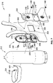
FIG. 7 . is an exploded view of a second embodiment of a back pack having a dive bladder. - While the invention will be described in connection with certain preferred embodiments, there is no intent to limit it to those embodiments.
-
FIG. 1 illustrates aback pack 10 for an underwaterbreathing gas tank 12. Theback pack 10 includes atank mounting structure 14 having afront surface 16 that faces away from an underwaterbreathing gas tank 12 when the underwaterbreathing gas tank 12 is operably mounted to thetank mounting structure 14. Thefront surface 16 faces towards a diver's back (not illustrated) when theback pack 10 is operably coupled to a diver for diving operations. Thetank mounting structure 14 defines arecess 18. Thefront surface 16 of thetank mounting structure 14 defines anopening 20 of therecess 18. Thetank mounting structure 14 defines a bottom surface 22 (FIG. 2 ) of therecess 18. Thebottom surface 22 of therecess 18 is opposite theopening 20 in thefront surface 16. - The back pack further includes a
strap 24 and abuckle 26. Thestrap 24 andbuckle 26 cooperate, as will be discussed in greater detail below, to permit the length of thestrap 24 to be infinitely adjusted (as opposed to straps that are pre-configured for fixed/discrete lengths) as its surrounds an underwaterbreathing gas tank 12 to secure the underwaterbreathing gas tank 12 to theback pack 10. The infinite adjustability provided by thebuckle 26 andstrap 24 advantageously allow for varying diameters of underwater breathing gas tanks to be couple to theback pack 10. As will be discussed in greater detail below, thebuckle 26 of theback pack 10 has a latched state (FIG. 1 ) and an unlatched state (FIG. 5 ) to permit adjustment of the length of thestrap 24. - In the latched state, the
buckle 26 fixes the length of thestrap 24 surrounding thetank mounting structure 14 and underwaterbreathing gas tank 10 so as to tightly secure an underwaterbreathing gas tank 12 to thetank mounting structure 14. Thestrap 24 in the latched state cannot move unless thebuckle 26 is unlatched to allow thestrap 24 to be adjusted. - As illustrated in
FIG. 1 , thebuckle 26 in the latched state may be positioned within therecess 18 between thebottom surface 22 of therecess 18 and theopening 20 defined by thefront surface 16. Theopening 20 of therecess 18 in thetank mounting structure 14 includes a portion that extends into aside tank mounting structure 14 as well as thefront surface 16. Thebuckle 26, in the latched state, is in therecess 18 between an underwaterbreathing gas tank 12 and a diver's back when the underwaterbreathing gas tank 12 is operably connected to thetank mounting structure 14 and a diver. In the latched state, thebuckle 26 may be in therecess 18 and does not extend out of theopening 20 either through thesides front surface 16. However, in other embodiments, thebuckle 26 in the latched state is positioned partially within therecess 18 and may extend at least partially beyond any one or more of theopening 20,front surface 16, and sides 19, 21. In such embodiments, thebuckle 26 is still advantageously positioned between thebottom surface 22 and a diver's back when theback pack 10 is operably worn on a diver's back. - Further, the
tank mounting structure 14 defines anouter periphery 28 of thetank mounting structure 14. In the latched state, ahandle 104 of thebuckle 26 does not extend out of, that is beyond, theouter periphery 28 defined by thetank mounting structure 14. The handle in the latched state is completely positioned within theouter periphery 28 of thetank mounting structure 14 to prevent it from becoming inadvertently unlatched. On the other hand, in the unlatched state of the buckle 26 (FIG. 5 ), thehandle 104 extends out, that is beyond theouter periphery 28 defined by thetank mounting structure 14 and in the unlatched state thehandle 104 is partially located outside therecess 18. - The latched
buckle 26 located entirely inside therecess 18 provides an advantage for a diver utilizing theback pack 10 for securing an underwaterbreathing gas tank 12 to thetank mounting structure 14. During a dive, a diver's back faces thefront surface 16 of thetank mounting structure 14. As such, the diver's back advantageously acts as a protective cover over therecess 18 concealing thebuckle 26 within it. Further, thebottom surface 22 of therecess 18 protects the opposite side of thebuckle 26 within therecess 18 from hitting structure or being hit by objects during a dive. In this way, thebuckle 26 is protected within therecess 18 from being inadvertently hit or bumped by an object or structure that would cause thebuckle 26 to come unlatched and separate theunderwater breathing tank 12 from theback pack 10. - Turning now to the exploded view of the
back pack 10 as illustrated inFIG. 2 , thetank mounting structure 14 ofFIG. 1 will be discussed in greater detail. Thetank mounting structure 14 may include a first mountingplate 30 that defines, at least in part, therecess 18 and a second mountingplate 32. The first mountingplate 30 has atop portion 34, amiddle portion 36, and abottom portion 38. Thetop portion 34 has a top mountingaperture 40. Thebottom portion 38 has abottom mounting aperture 42. The mountingapertures plate 32. In alternative embodiments, thetank mounting structure 14 may be made of a single mounting plate. Further, as can be readily appreciated the structures and contours, such asrecess 18 and handle 28, maybe made in certain embodiments on either one of the plates or in embodiments that comprise only a single mounting plate for the tank mounting structure. - The
top portion 34 of the first mountingplate 30 further includes a topconcave portion 44 of thefront face 16 of thetank mounting structure 14 and a carryinghandle 46. The carryinghandle 46 is canted such that it extends away from agas tank 12 when the underwaterbreathing gas tank 12 is operably mounted to thetank mounting structure 14. Thehandle 46 includes ahandle aperture 48 that extends through thefront surface 16 and aback surface 50 of the first mountingplate 30. Theback pack 10 can be advantageously transported via thehandle 46 built into the first mountingplate 30. As previously discussed, in yet other embodiments, thehandle 46 may be built into or carried by the second mountingplate 32 and in yet other embodiments where thetank mounting structure 14 is a single mounting plate, thehandle 46 may be built into or carried by the single mounting plate. One of the advantages of thehandle 46 position is that thehandle 46 does not interfere with either the underwaterbreathing gas tank 12 or the diver during a dive because of its advantageous extension away from the underwaterbreathing gas tank 12 while at the same time allowing tight contact between theback pack 10, the diver and an underwaterbreathing gas tank 12. Thetop portion 34 of thetank mounting structure 14 extends longitudinally between theoutermost periphery 28 at the carryinghandle 46 and anupper edge 52 of theopening 20 of therecess 18 in thefront surface 16. - The
middle portion 36 of the first mountingplate 30 extends longitudinally between theupper edge 52 and abottom edge 54 of theopening 20 of therecess 18 in thefront surface 16. Themiddle portion 36 includes therecess 18 and afirst side wall 56 and asecond sidewall 58 of therecess 18. Thesidewalls - The
bottom portion 38 of the first mountingplate 30 extends longitudinally between thebottom edge 54 of the opening of therecess 18 and abottom 118 of the first mountingplate 30. Thebottom portion 38 defines a bottomconcave portion 62 of thefront surface 16 of thetank mounting structure 14. Thebottom portion 38 further includes opposedwings 64 that extend away from an underwaterbreathing gas tank 12 when operably coupled to thetank mounting structure 14. Theopposed wings 64 advantageously provide for a tight fit between theback pack 10 and a diver. The advantageous contour of thewings 64 together with the bottomconcave portion 62 conform to the contour of the diver's back to provide for the comfortable and tight fit. - The
tank mounting portion 14 also includes the second mountingplate 32. Thesecond mounting plate 32 defines, at least in part, thebottom surface 22 of therecess 18 opposite theopening 20 in thefront surface 16. Thesecond mounting plate 32 is located between the first mountingplate 30 and the underwaterbreathing gas tank 12 when the underwaterbreathing gas tank 12 is mounted to thetank mounting structure 14. Thesecond mounting plate 32 includes atop portion 64,middle portion 66 andbottom portion 68 that are designed to mount totop portion 34, themiddle portion 36, and thebottom portion 38 of the first mounting plate, respectively. Thetop portion 64 includes a topapertured mounting boss 70. The top 64 further includes topmale mounting members 72 in spaced relation. Thetop portion 64 further includes a convexfront surface 74. - The
middle portion 66 of the second mountingplate 32 defines u shapedchannel 76 having anupper wall 78, alower wall 80 and abottom wall 82. Thebottom wall 82 includes thebottom surface 22 of therecess 18 and extends between the upper andlower walls buckle 26 is permitted to remain at least partially betweenbottom surface 22 of the recess and the diver's back when an underwaterbreathing gas tank 12 is operably connected to thetank mounting structure 14 and a diver. - The
bottom portion 68 of the second mountingplate 32 includes a bottom apertured mountingboss aperture 84 and bottommale mounting members 86 in opposed space relation. Thebottom portion 68 further includes a bottom convexfront surface 88. - Still with respect to
FIG. 2 , buckle 26 of theback pack 10 is illustrated.Buckle 26 includes anupper arm member 90 and alower arm member 92 that are spaced apart from one another. Thearm members lower arm 92 will be described as theupper arm 90 mirrors thelower arm 92. Thelower arm member 92 has at a first end 94, a first aperture 96, a second aperture 98 and athird aperture 100. Abottom mounting pin 102 passes through the first aperture 96 and into thelower wall 80 to pivotally connect thebuckle 26 to the second mountingplate 32. Atop mounting pin 103 passes through an aperture in theupper arm 90 and into theupper wall 78 to pivotally connect thebuckle 26 to the second mountingplate 32. Thebottom mounting pin 102 and thetop mounting pin 103 define an axis of rotation 124 (seeFIG. 5 ) about which thebuckle 26 may pivot to provide the over the center function to secure thestrap 24 in moving from the unlatched state (FIG. 5 ) to the latched state (FIG. 6 ). However, unlike a traditional or standard cam over-center buckle, buckle 26 remains closed, that is, remains in a latched state by itself with no additional locking mechanism necessary. Further, although a cinch in the form ofbuckle 26 is discussed with respect to the illustrated embodiment, it may be readily appreciated the cinch is not limited to embodiments ofbuckle 26. Other embodiments with varying structures for the cinch may be utilized to provide the over center function. - The
buckle 26 is manipulated by a diver between its latched state and unlatched state via the buckle handle 104 located at asecond end 106 of thebuckle 26 opposite the first end 94. The buckle handle 104 has a generallyrectangular buckle face 108. Buckle handle 104 connectsupper arm member 90 andlower arm member 92. Further, connection between theupper arm member 90 and lower arm member is provided by afirst buckle pin 110 having a first end that is fixed in the second aperture 98 of thelower member 92 and a second end that is fixed in the corresponding aperture of theupper arm member 90. Asecond buckle pin 112 has a first end that pass into thethird aperture 100 of thelower arm member 92 and a second end that is fixed in the corresponding aperture of theupper arm member 90. - Buckle pins 110, 112 may be press fit into the apertures, welded or soldered so as to connect the upper 90 and lower 92 arm members via buckle pins 110, 112. In yet other embodiments, the buckle pins 110, 112 may pass through the
buckle 26 through either or both of upper 90 and lower 92 members to connect totank mounting structure 14. In the embodiment illustrated, buckle pins 110 and 112 permit thestrap 24 to change direction as it passes through thebuckle 26 so as to create the necessary torque and friction to allow the over the center function of thebuckle 26 to fix the length of thestrap 24. - In addition to buckle pins 110,112 recess pins 114 and 116 assist in the over the center function of the
buckle 26. Recess pins 114, 116 do not pass through thebuckle 26 but do traverse and thereby connectupper wall 78 of the second mountingplate 32 withlower wall 80 of therecess 18 to create a pathway through which strap 24 may pass.Strap 24 has afirst end 120 that wraps around and may pivotally attach to recesspin 116 while asecond end 122 of thestrap 24 is free to pass around the underwaterbreathing gas tank 12 and then back into therecess 18 and throughbuckle 26 to fix the length of thestrap 24 so as to tightly hold theback pack 10 to the underwaterbreathing gas tank 12. - Turning to
FIG. 3 , theback surface 50 of the first mountingplate 30 is illustrated. Thetop mounting aperture 40 andbottom aperture 42 traverse thefront surface 16 and back surface 50 as does thehandle aperture 48. Theback surface 50 of thetop portion 34 of the first mountingplate 30 also defines a top backconcave surface 126. Theback surface 50 of thebottom portion 38 of the first mountingplate 30 also defines a bottom backconcave surface 128. The backconcave surfaces front surface 74 of thetop portion 64 of the second mountingplate 32 and the bottom convexfront surface 88. The backconcave surfaces convex surface 74 and bottomconvex surface 88 of the second mountingplate 32 when joined to the first mountingplate 30. - The
back surface 50 of the first mountingplate 30 also includes a pair of back topportion receiving apertures 130 and back bottomportion receiving apertures 132. The receivingapertures male mounting members 72 and bottommale mounting members 86 to provide a press fit there between when the first mountingplate 30 and second mountingplate 32 are joined. So too, it can be readily appreciated that the top and bottomapertured mounting bosses bottom mounting apertures - Turning to
FIG. 4 , theback surface 60 of the second mountingplate 32 is illustrated. Theback surface 60 includes concave backtop surface 134, the concave backbottom wall surface 136 and concave backbottom surface 138. The apertures of the top and bottomapertured mounting bosses bottom surfaces breathing gas tank 12 to provide a tight fit when joined together during diving operations. Concave backbottom wall surface 136 advantageously protects in part thebuckle 26 in its latched state inrecess 18 such thatbuckle 26 cannot be hit by an obstacle or structure during a dive. - As illustrated in
FIGS. 2-4 the first mountingplate 30 and second mountingplate 32 may be releasably connected. The convex surfaces 74, 88 of the second mountingplate 32 are complimentary to the concave surfaces 126,128 of the first mountingplate 30 and cooperate in their contoured fit to assist in joining with strength the first and second mountingplates male mounting members apertures plates apertured mounting bosses plate 32 are received into the top andbottom mounting apertures plate 30 when the first and second mountingplates - With additional reference to
FIG. 2 , the joining of the first and second mountingplates fasteners 140 that are inserted through the top and bottomapertured mounting bosses bottom mounting apertures plate 30. Anut 142 attaches to eachfastener 140 within the respective top andbottom mounting aperture nut 142 is tightened the first and second mountingplates nuts 142 rest inside their respective top andbottom mounting apertures front surface 16. - When the first and second mounting
plates upper wall 78 andlower wall 80 pass into the opening in therecess 18 to define together withsidewalls channel 76 of therecess 18 in which thebuckle 26 resides in its latched state. -
FIGS. 5 and 6 illustrate the cross section of thebuckle 26 and thestrap 24 throughrecess 18 about line 5-5 ofFIG. 1 .FIG. 5 illustrates thebuckle 26 in the latched state andFIG. 6 illustrates the buck in the latched state. - To create the over the center function of the
buckle 26, fixedend 120 ofstrap 24 is attached to recesspin 116 such that it may pivot aboutrecess pin 116. Thestrap 24 extends through afirst gap 146 in therecess 18 betweenside wall 58 of therecess 18 and an edge 83 ofbottom wall 82 as it is wrapped counter clockwise in the illustrated figures around anunderwater breathing gas 12 for diving operations. Clockwise and counterclockwise are used simply for illustrative purposes with respect to the drawings. Oncestrap 24 completely surrounds an underwaterbreathing gas tank 12, thestrap 24 is passed through asecond gap 148 in therecess 18 between anedge 85 of theside wall 56 of therecess 18 and thebottom wall 82 of therecess 18. Thereafter, thestrap 24 is wrapped counter clockwise aroundbuckle pin 112 and inserted between buckle pins 112 and 110 such thatstrap 24 wraps clock wise aroundbuckle pin 110.Strap 24 then passes clockwise aroundrecess pin 118 and passes betweenrecess pin 118 andrecess pin 116.Free end 122 ofstrap 24 is then wrapped counterclockwise aroundbuckle pin 116 with thebuckle 26. - By unlatched state of the
buckle 26 it is meant that thestrap 24 is adjustable such that it may be tightened or loosened by decreasing or increasing its length as it surrounds an underwaterbreathing gas tank 12. In the unlatched state, buckle handle 104 is located at least partially outside therecess 18 such that thebuckle front face 108 is facing toward the underwaterbreathing gas tank 12 while the buckle back face 107 faces away from the underwaterbreathing gas tank 12 and towards a diver's back when the underwaterbreathing gas tank 12 is placed in a position to be operably coupled to thetank mounting structure 14. In the unlatched state of thebuckle 26, the outermost periphery of the buckle at thesecond end 106 is outside of therecess 18 extending laterally beyondside wall 56 such that buckle front and back faces 106, 107 are generally parallel to thebottom surface 22 of therecess 18. A portion of thehandle 104 of thebuckle 26 extends into a portion of therecess 18 that extends into theside tank mounting structure 14 when thebuckle 26 is in the unlatched state. This provides a visual indication to the diver that thebuckle 26 is unlatched. It also allows the diver to easily grip and apply force to thebuckle 26 to transition it into the latched state. - In the unlatched state of the
buckle 26, the length of thestrap 26 is adjusted by pulling on thefree end 122 of thestrap 24 to move the strap in a generally counterclockwise manner to tighten and thus shorten the length of thestrap 24 length as it surrounds an underwaterbreathing gas tank 12. On the other hand, the length of thestrap 24 as it surrounds the underwaterbreathing gas tank 12 may be increased, that is loosened in the open state of thebuckle 26 by pulling on any part of thestrap 24 away from thefixed end 120 to move thestrap 24 in a generally clockwise direction.Strap 24 may also have pre-configured visible lines (not illustrated) along its length for alignment with thetank mounting structure 14,buckle 26 or thestrap 24 or all to advantageously provide a visible reference for adjusting the length of thestrap 24 to tightly fit around varying predetermined circumferences of underwater breathing gas tank as they are operably coupled to thetank mounting structure 14. - Also illustrated in
FIG. 5 isbottom mounting pin 102 which together with top mounting pin 104 (not illustrated inFIG. 6 ) defines therotation axis 124 about whichbuckle 26 rotates as it passes between the unlatched state of the buckle 26 (which may also be interchangeably referred to as the open state of the buckle 26) and the latched state of the buckle 26 (which may also be interchangeably referred to as the closed state of the buckle 26). -
Buckle 26 is manipulated to rotate in a counterclockwise rotation aboutrotation axis 124 to transition from the unlatched state to the latched state. In transition, at least a portion of thehandle 104 extends out of theopening 20 of therecess 18 beyond thefront surface 16. Thebuckle 26 is an over center mechanism such that in the latched state, thestrap 24 creates aforce 156 that is directed to generate a latchingtorque 158 in a first angular direction on thebuckle 26 around therotational axis 124 biasing thebuckle 26 toward the latched state and maintaining the buckle in the latched state. In the latched state, theforce 156 generated by thestrap 24 on thebuckle 26 lies on afirst side 160 ofrotational axis 124. In the unlatched state, thestrap 24 creates aforce 162 that generates atorque 164 on thebuckle 26, in a direction oppositetorque 158, around therotational axis 124 biasing thebuckle 26 toward the unlatched state. In the unlatched state theforce 162 acts on an opposite second side 166 ofrotational axis 124 asforce 156. - As illustrated in
FIG. 6 , when thebuckle 26 is in the latched state the length of thestrap 24 is fixed and thebuckle 26 is located entirely within therecess 18 such that it does not extend beyond thefront surface 16 or thesides tank mounting structure 14. In the latched state, thefront face 108 of thebuckle 26 is located entirely withinrecess 18 andopening 20 such that thefront face 108 does not extend beyondfront face 16 of thetank mounting structure 14. Advantageously, in the latched state, when in a dive, thebuckle 26 is protected from becoming inadvertently unlatched, because it is protected by thebottom wall 82 of therecess 18 as well as a diver's back overopening 20 such that an object or structure cannot penetrate therecess 18 to generate enough force to overcome the torque keeping the over-the-center buckle 26 closed in the latched state. - Further the
handle 104 is advantageously dimensioned such that its length prevents rotation from the latched state to the unlatched state when worn by a diver as thehandle 104 will hit the diver's back prior to being able to be rotated to the unlatched state. The particular relevant dimension is the distance fromrotation axis 124 relative to spacing betweenrotation axis 124 and a diver's back when worn. Accordingly, in other embodiments,tank mounting structure 14 provides for arecess 18 that receives abuckle 26 such thatbuckle 26 may extend beyond opening 20 andfront face 16 towards a divers back. In such embodiments, at least a portion ofbuckle 26 remains in therecess 18. In the latched state, when thetank mounting structure 14 is worn on a diver's back, the diver's back prevents thebuckle 26 from inadvertently transitioning from the latched state to the unlatched state. - Turning now to
FIG. 7 ,back pack 110 is illustrated. Back pack 210 is identical to backpack 10 exceptback pack 210 includesdive bladder 344. - The
back pack 210 for an underwaterbreathing gas tank 212 includes afirst mounting plate 230 and asecond mounting plate 232 releasably coupled to one another. By releasably coupled it is understood that the first and second mountingplates plates - The first and second mounting
plates front surface 216 facing away from agas tank 212 when agas tank 212 is operably mounted to the tank mounting structure 214. The tank mounting structure 214 defines arecess 218. Thefront surface 216 defines anopening 220 of therecess 218. The tank mounting structure 214 defines abottom surface 222 of therecess 218 opposite theopening 220 in thefront surface 216. Theback pack 210 includes thedive bladder 344 that is releasably coupled between the first and second mountingplates - The
dive bladder 344 includes a first 350 and second 352 dive bladder aperture. The firstdive bladder aperture 350 aligns with the topapertured mounting boss 270 of thesecond mounting plate 232 and thetop mounting aperture 240 of the first mountingplate 230 such thatfastener 340 may be easily inserted therethrough and fastened withnut 342. The seconddive bladder aperture 352 aligns with the bottomapertured mounting boss 284 of thesecond mounting plate 232 and thebottom mounting aperture 242 of the first mountingplate 230 such thatfastener 340 may be easily inserted therethrough and fastened withnut 342. -
Dive bladder 344 may further include a thirddive bladder aperture 354 located between the first and seconddive bladder apertures dive bladder aperture 354 is formed such that it permits the upper 278 and lower 280 walls of themiddle portion 266 of thesecond mounting plate 232, the top 272 and bottom 286 male mounting members and the first 256 and second 258 side walls of therecess 218 to pass therethrough as the first 230 and second 232 mounting plates are joined to form the tank mounting structure 214. -
Dive bladder 344 is made of a material that is flexible enough to permit thedive bladder 344 to conform to the convex front surfaces of thesecond mounting plate 232 and the concave back surfaces of the first mountingplate 230 such that they cooperate with one another to ensure a tight fit between the first 230 and second 232 mounting plates when they are releasably joined together in the manner heretofore discussed. Specifically, thedive bladder 344 may be a single bladder made of high frequency weldable fabric such as polyurethane coated nylon fabric (210, 420, 840 or 1000 denier) or divebladder 344 may be a double bladder that includes a polyurethane inner air-cell and an outer bladder made of nylon fabric just discussed but without the polyurethane coat. - Back pack 210 further includes the over the
center buckle 226 and thestrap 324. The first end of the 320 of thestrap 324 is pivotally attached the over thecenter buckle 226. The overcenter buckle 226 receives thesecond end 322 of thestrap 322 for securing thestrap 324 in a fixed position. Thestrap 324 in its fixed position surrounds an underwaterbreathing gas tank 212, thedive bladder 344, the tank mounting structure when an underwaterbreathing gas tank 212 is operably connected to theback pack 210 for a dive. When thestrap 324 is in the fixed position, thebuckle 226 is located within therecess 218 between thebottom surface 222 and theopening 220 defined by thefront surface 216 of the tank mounting structure 214. - With reference to back
packs tank mounting structure 14, 214 may be made of fiberglass reinforced nylon. Thefastener nut buckle strap - The use of the terms "a" and "an" and "the" and similar referents in the context of describing the invention (especially in the context of the following claims) is to be construed to cover both the singular and the plural, unless otherwise indicated herein or clearly contradicted by context. The terms "comprising," "having," "including," and "containing" are to be construed as open-ended terms (i.e., meaning "including, but not limited to,") unless otherwise noted. Recitation of ranges of values herein are merely intended to serve as a shorthand method of referring individually to each separate value falling within the range, unless otherwise indicated herein, and each separate value is incorporated into the specification as if it were individually recited herein. All methods described herein can be performed in any suitable order unless otherwise indicated herein or otherwise clearly contradicted by context. The use of any and all examples, or exemplary language (e.g., "such as") provided herein, is intended merely to better illuminate the invention and does not pose a limitation on the scope of the invention unless otherwise claimed. No language in the specification should be construed as indicating any non-claimed element as essential to the practice of the invention.
- Preferred embodiments of this invention are described herein, including the best mode known to the inventors for carrying out the invention. Variations of those preferred embodiments may become apparent to those of ordinary skill in the art upon reading the foregoing description.
Claims (8)
- A back pack (10) for an underwater breathing gas tank (12) comprising:a tank mounting structure (14) having a front surface (16) facing away from an underwater breathing gas tank (12) when an underwater breathing gas tank (12) is operably mounted to the tank mounting structure (14), the tank mounting structure (14) defining a recess (18), the front surface (16) defining an opening (20) of the recess (18), the tank mounting structure (14) defining a bottom surface (22) of the recess (18) opposite the opening in the front surface (16);a strap (24);a buckle (26) having a latched state for securing the strap (24) in a fixed position for securing a underwater breathing gas tank (12) to the tank mounting structure (14), the buckle (26), when in a latched state, positioned at least partially within the recess (18),characterized in that the tank mounting structure (14) includes a first mounting plate (30) defining, at least in part, the recess (18) and a second mounting plate (32) defining at least in part, the bottom of the recess (18) opposite the opening in the front surface.
- The back pack of claim 1, wherein the buckle (26) is pivotably attached to the tank mounting structure (14) for rotation about a first rotational axis, the buckle (26) is an over-center mechanism such that in the latched state, the strap (24) generates a torque on a latch in a first direction around the rotational axis biasing the latch toward the latched state and, in the unlatched state, any torque generated by the strap (24) biases the buckle (26) in an opposite second direction around the rotational axis toward an unlatched state.
- The back pack of claim 1, wherein the second mounting plate (32) is located between the first mounting plate (30) and a gas tank (12) when a gas tank (12) is mounted to the tank mounting structure (14) or wherein preferably a dive bladder (344) is fixed between the first mounting plate (30) and the second mounting plate (32).
- The back pack of claim 1, wherein the strap (24) extends around at least a portion of the gas tank (12) when operably mounted to the tank mounting structure (14) and wherein the strap (24) has a first end and a second end, the first end is attached to the buckle (26) and the second end is adjustable relative to the buckle (26) to fix a length of the strap (24) when the buckle (26) is in the latched state such that underwater breathing gas tanks (12) of different sizes can be secured to the tank mounting structure (14).
- The back pack of claim 1, wherein the buckle (26), in the latched state, is between the front surface (16) of the tank mounting structure (14) and a diver's back when a gas tank (12) is operably connected to the tank mounting structure (14) and a diver;
or the buckle (26) in the latched state is positioned within the recess (18) between the bottom surface (22) and the opening in the front surface (16). - The back pack of claim 1, wherein in the latched state, the buckle (26) is entirely within the recess (18) and does not extend out of the opening, wherein preferably when the buckle (26) transitions between an unlatched state and the latched state, a handle portion of the buckle (26) extends out of the opening beyond the front surface (16).
- The back pack of claim 1, wherein the opening of the recess (18) in the tank mounting structure (14) includes a portion that extends into a side of the tank mounting structure (14) as well as the front surface(16);
a handle portion of the buckle (26) extends into the portion of the recess (18) that extends into the side of the tank mounting structure when the buckle (26) is in an unlatched state. - The back pack of claim 7, wherein the tank mounting structure (14) defines an outer periphery (28) and the handle (104) extends out of the outer periphery (28) defined by the tank mounting structure (14) in the unlatched state and is at least partially within the outer periphery (28) in the latched state.
Priority Applications (1)
| Application Number | Priority Date | Filing Date | Title |
|---|---|---|---|
| EP22158280.2A EP4023543B1 (en) | 2016-09-22 | 2017-09-20 | Back pack for underwater breathing tank |
Applications Claiming Priority (2)
| Application Number | Priority Date | Filing Date | Title |
|---|---|---|---|
| US15/273,238 US9889911B1 (en) | 2016-09-22 | 2016-09-22 | Back pack cinch |
| PCT/US2017/052433 WO2018057581A1 (en) | 2016-09-22 | 2017-09-20 | Back pack cinch |
Related Child Applications (2)
| Application Number | Title | Priority Date | Filing Date |
|---|---|---|---|
| EP22158280.2A Division-Into EP4023543B1 (en) | 2016-09-22 | 2017-09-20 | Back pack for underwater breathing tank |
| EP22158280.2A Division EP4023543B1 (en) | 2016-09-22 | 2017-09-20 | Back pack for underwater breathing tank |
Publications (3)
| Publication Number | Publication Date |
|---|---|
| EP3515806A1 EP3515806A1 (en) | 2019-07-31 |
| EP3515806A4 EP3515806A4 (en) | 2020-05-20 |
| EP3515806B1 true EP3515806B1 (en) | 2022-08-03 |
Family
ID=61147869
Family Applications (2)
| Application Number | Title | Priority Date | Filing Date |
|---|---|---|---|
| EP17853785.8A Active EP3515806B1 (en) | 2016-09-22 | 2017-09-20 | Back pack cinch |
| EP22158280.2A Active EP4023543B1 (en) | 2016-09-22 | 2017-09-20 | Back pack for underwater breathing tank |
Family Applications After (1)
| Application Number | Title | Priority Date | Filing Date |
|---|---|---|---|
| EP22158280.2A Active EP4023543B1 (en) | 2016-09-22 | 2017-09-20 | Back pack for underwater breathing tank |
Country Status (4)
| Country | Link |
|---|---|
| US (1) | US9889911B1 (en) |
| EP (2) | EP3515806B1 (en) |
| DE (1) | DE202017007247U1 (en) |
| WO (1) | WO2018057581A1 (en) |
Families Citing this family (7)
| Publication number | Priority date | Publication date | Assignee | Title |
|---|---|---|---|---|
| GB2573332B (en) * | 2018-05-04 | 2022-05-04 | Draeger Safety Uk Ltd | Back plate for a breathing apparatus |
| US20200383866A1 (en) * | 2019-06-06 | 2020-12-10 | Alan Scott Crarer | Therapeutic Roller Bracing System |
| USD1005431S1 (en) * | 2019-09-20 | 2023-11-21 | Rhys James Couzyn | Scuba diving backplate |
| EP3871739B1 (en) * | 2020-02-26 | 2024-12-18 | Draeger Safety UK Limited | Cylinder-retaining apparatus for a breathing apparatus |
| USD975432S1 (en) | 2020-11-24 | 2023-01-17 | Frog Physics, LLC | Backpack frame |
| US11759001B1 (en) | 2020-12-23 | 2023-09-19 | Frog Physics, LLC | Backpack frame system |
| EP4292668A1 (en) * | 2022-06-16 | 2023-12-20 | Dräger Safety AG & Co. KGaA | Support frame for a breathing apparatus |
Family Cites Families (26)
| Publication number | Priority date | Publication date | Assignee | Title |
|---|---|---|---|---|
| US3033431A (en) * | 1960-08-08 | 1962-05-08 | Robert B Henderson | Back plate for self-contained underwater breathing apparatus |
| US3957183A (en) | 1974-03-14 | 1976-05-18 | U.S. Divers Company | Backpack for breathing tanks |
| US4310110A (en) | 1980-01-21 | 1982-01-12 | Under Sea Industries, Inc. | Scuba tank harness |
| US4690314A (en) | 1985-08-26 | 1987-09-01 | Mark Faulconer | Buoyancy compensator insertable backpack |
| US4778307A (en) | 1986-12-23 | 1988-10-18 | U.S. Divers Company | Buoyancy compensator with an adjustable strap |
| JPH0225389U (en) * | 1988-08-08 | 1990-02-20 | ||
| US5046894A (en) | 1990-07-12 | 1991-09-10 | Soniform, Inc. | Buoyancy compensator with interchangeable backpack and commerbund |
| US5378084A (en) | 1991-11-18 | 1995-01-03 | Walters; William D. | Backpack systems |
| US5346419A (en) | 1993-05-14 | 1994-09-13 | International Divers Inc. | Buoyancy compensator device with backpack and adjustable harness |
| US5522679A (en) | 1994-06-02 | 1996-06-04 | Dacor Corporation | Buoyancy compensator having attached backpack |
| US5567084A (en) | 1995-02-24 | 1996-10-22 | Sea Quest, Inc. | Buoyancy compensator with a traction pressure pad |
| US5662433A (en) | 1995-10-17 | 1997-09-02 | Sea Quest, Inc. | Body conforming vest, buoyancy compensator, and backpack |
| US5626439A (en) | 1995-12-07 | 1997-05-06 | Rowlands; Albert J. | Diver's vest having compressed air tightening device |
| IT248403Y1 (en) | 1999-07-28 | 2003-01-28 | Htm Sport Spa | BACKREST FOR CYLINDERS FOR DIVING |
| US6402429B1 (en) | 1999-08-20 | 2002-06-11 | Zeagle Systems, Inc. | Buoyancy compensator harness system |
| US20020009335A1 (en) | 2000-07-18 | 2002-01-24 | Courtney William L. | Vertically eccentric, horizontally symmetric, mobile and fixed buoyant in combination with mobile and fixed ballast as a type a personal flotation device |
| JP3771447B2 (en) | 2001-01-16 | 2006-04-26 | 株式会社タバタ | Diving jacket |
| WO2004056651A2 (en) | 2002-12-17 | 2004-07-08 | Sharkbait, Llc | Mounting system |
| US6749370B1 (en) | 2003-03-11 | 2004-06-15 | Tabata Co., Ltd. | Buoyancy compensating jacket |
| JP3994080B2 (en) | 2003-10-06 | 2007-10-17 | 株式会社タバタ | Cylinder fixing device |
| US7367749B2 (en) | 2003-11-19 | 2008-05-06 | Sancheong Co. Ltd. | Backpack |
| US7052211B1 (en) | 2005-05-06 | 2006-05-30 | Curry Michael B | Buoyancy compensating device protective cover |
| US7540690B2 (en) | 2005-10-03 | 2009-06-02 | G Albert Hreish | Adjustable size buoyancy compensator |
| US8006877B2 (en) | 2007-04-18 | 2011-08-30 | Sperian Respiratory Protection Usa, Llc | Backpack for self contained breathing apparatus |
| US8398337B2 (en) | 2009-06-05 | 2013-03-19 | Halcyon Manufacturing, Inc. | Continuous weave quick harness backplate system |
| US9586065B2 (en) * | 2013-11-27 | 2017-03-07 | Msa Technology, Llc | Modular tank cradle and backpack for self-contained breathing apparatus |
-
2016
- 2016-09-22 US US15/273,238 patent/US9889911B1/en active Active
-
2017
- 2017-09-20 EP EP17853785.8A patent/EP3515806B1/en active Active
- 2017-09-20 WO PCT/US2017/052433 patent/WO2018057581A1/en not_active Ceased
- 2017-09-20 DE DE202017007247.5U patent/DE202017007247U1/en active Active
- 2017-09-20 EP EP22158280.2A patent/EP4023543B1/en active Active
Also Published As
| Publication number | Publication date |
|---|---|
| EP3515806A4 (en) | 2020-05-20 |
| WO2018057581A1 (en) | 2018-03-29 |
| DE202017007247U1 (en) | 2020-04-23 |
| US9889911B1 (en) | 2018-02-13 |
| EP4023543B1 (en) | 2024-06-19 |
| EP3515806A1 (en) | 2019-07-31 |
| EP4023543A2 (en) | 2022-07-06 |
| EP4023543A3 (en) | 2022-10-05 |
Similar Documents
| Publication | Publication Date | Title |
|---|---|---|
| EP4023543B1 (en) | Back pack for underwater breathing tank | |
| US10138047B2 (en) | Spigot and spigot guard for an insulating container | |
| US11608213B2 (en) | Spigot and spigot guard for an insulating container | |
| US4310110A (en) | Scuba tank harness | |
| US3957183A (en) | Backpack for breathing tanks | |
| US6212919B1 (en) | Adjustable cable loop locking system for securing a pair of spacially separated articles together | |
| US20040082238A1 (en) | Diving back plate | |
| US4558726A (en) | Hammer with replaceable head | |
| US4918790A (en) | Cam buckle | |
| EP3687893B1 (en) | Back pack cinch | |
| EP4249395A2 (en) | Spigot and spigot guard for an insulating container | |
| HK40068525B (en) | Back pack for underwater breathing tank | |
| US4641874A (en) | Portaging device | |
| HK40068525A (en) | Back pack for underwater breathing tank | |
| CN109501982B (en) | Quick-assembly tank tightener | |
| US11533984B2 (en) | Holster | |
| US6367753B1 (en) | Pony tank quick release | |
| US8033274B2 (en) | Spear gun with an adjustable grip | |
| US20210045505A1 (en) | A watch anti-theft device and watch strap combination, and a device for the combination | |
| US20060272635A1 (en) | Snorkel retaining clip | |
| EP3825225B1 (en) | Buoyancy control jacket for scuba diving | |
| KR101954091B1 (en) | Side mount type scuba tank holding band | |
| US20240138527A1 (en) | Fastening device for air cylinder | |
| US11478066B2 (en) | Baton scabbard | |
| US20060018718A1 (en) | Connector having a mechanical lock and a one-step release |
Legal Events
| Date | Code | Title | Description |
|---|---|---|---|
| REG | Reference to a national code |
Ref country code: DE Ref legal event code: R138 Ref document number: 202017007247 Country of ref document: DE Free format text: GERMAN DOCUMENT NUMBER IS 602017060312 |
|
| STAA | Information on the status of an ep patent application or granted ep patent |
Free format text: STATUS: THE INTERNATIONAL PUBLICATION HAS BEEN MADE |
|
| PUAI | Public reference made under article 153(3) epc to a published international application that has entered the european phase |
Free format text: ORIGINAL CODE: 0009012 |
|
| STAA | Information on the status of an ep patent application or granted ep patent |
Free format text: STATUS: REQUEST FOR EXAMINATION WAS MADE |
|
| 17P | Request for examination filed |
Effective date: 20190418 |
|
| AK | Designated contracting states |
Kind code of ref document: A1 Designated state(s): AL AT BE BG CH CY CZ DE DK EE ES FI FR GB GR HR HU IE IS IT LI LT LU LV MC MK MT NL NO PL PT RO RS SE SI SK SM TR |
|
| AX | Request for extension of the european patent |
Extension state: BA ME |
|
| DAV | Request for validation of the european patent (deleted) | ||
| DAX | Request for extension of the european patent (deleted) | ||
| A4 | Supplementary search report drawn up and despatched |
Effective date: 20200422 |
|
| RIC1 | Information provided on ipc code assigned before grant |
Ipc: B63C 11/22 20060101AFI20200416BHEP |
|
| STAA | Information on the status of an ep patent application or granted ep patent |
Free format text: STATUS: EXAMINATION IS IN PROGRESS |
|
| 17Q | First examination report despatched |
Effective date: 20210326 |
|
| GRAP | Despatch of communication of intention to grant a patent |
Free format text: ORIGINAL CODE: EPIDOSNIGR1 |
|
| STAA | Information on the status of an ep patent application or granted ep patent |
Free format text: STATUS: GRANT OF PATENT IS INTENDED |
|
| INTG | Intention to grant announced |
Effective date: 20211028 |
|
| GRAJ | Information related to disapproval of communication of intention to grant by the applicant or resumption of examination proceedings by the epo deleted |
Free format text: ORIGINAL CODE: EPIDOSDIGR1 |
|
| STAA | Information on the status of an ep patent application or granted ep patent |
Free format text: STATUS: EXAMINATION IS IN PROGRESS |
|
| GRAP | Despatch of communication of intention to grant a patent |
Free format text: ORIGINAL CODE: EPIDOSNIGR1 |
|
| STAA | Information on the status of an ep patent application or granted ep patent |
Free format text: STATUS: GRANT OF PATENT IS INTENDED |
|
| INTC | Intention to grant announced (deleted) | ||
| INTG | Intention to grant announced |
Effective date: 20220304 |
|
| GRAS | Grant fee paid |
Free format text: ORIGINAL CODE: EPIDOSNIGR3 |
|
| GRAA | (expected) grant |
Free format text: ORIGINAL CODE: 0009210 |
|
| STAA | Information on the status of an ep patent application or granted ep patent |
Free format text: STATUS: THE PATENT HAS BEEN GRANTED |
|
| AK | Designated contracting states |
Kind code of ref document: B1 Designated state(s): AL AT BE BG CH CY CZ DE DK EE ES FI FR GB GR HR HU IE IS IT LI LT LU LV MC MK MT NL NO PL PT RO RS SE SI SK SM TR |
|
| REG | Reference to a national code |
Ref country code: AT Ref legal event code: REF Ref document number: 1508543 Country of ref document: AT Kind code of ref document: T Effective date: 20220815 Ref country code: CH Ref legal event code: EP |
|
| REG | Reference to a national code |
Ref country code: DE Ref legal event code: R096 Ref document number: 602017060312 Country of ref document: DE |
|
| REG | Reference to a national code |
Ref country code: IE Ref legal event code: FG4D |
|
| REG | Reference to a national code |
Ref country code: LT Ref legal event code: MG9D |
|
| REG | Reference to a national code |
Ref country code: NL Ref legal event code: MP Effective date: 20220803 |
|
| PG25 | Lapsed in a contracting state [announced via postgrant information from national office to epo] |
Ref country code: SE Free format text: LAPSE BECAUSE OF FAILURE TO SUBMIT A TRANSLATION OF THE DESCRIPTION OR TO PAY THE FEE WITHIN THE PRESCRIBED TIME-LIMIT Effective date: 20220803 Ref country code: RS Free format text: LAPSE BECAUSE OF FAILURE TO SUBMIT A TRANSLATION OF THE DESCRIPTION OR TO PAY THE FEE WITHIN THE PRESCRIBED TIME-LIMIT Effective date: 20220803 Ref country code: PT Free format text: LAPSE BECAUSE OF FAILURE TO SUBMIT A TRANSLATION OF THE DESCRIPTION OR TO PAY THE FEE WITHIN THE PRESCRIBED TIME-LIMIT Effective date: 20221205 Ref country code: NO Free format text: LAPSE BECAUSE OF FAILURE TO SUBMIT A TRANSLATION OF THE DESCRIPTION OR TO PAY THE FEE WITHIN THE PRESCRIBED TIME-LIMIT Effective date: 20221103 Ref country code: NL Free format text: LAPSE BECAUSE OF FAILURE TO SUBMIT A TRANSLATION OF THE DESCRIPTION OR TO PAY THE FEE WITHIN THE PRESCRIBED TIME-LIMIT Effective date: 20220803 Ref country code: LV Free format text: LAPSE BECAUSE OF FAILURE TO SUBMIT A TRANSLATION OF THE DESCRIPTION OR TO PAY THE FEE WITHIN THE PRESCRIBED TIME-LIMIT Effective date: 20220803 Ref country code: LT Free format text: LAPSE BECAUSE OF FAILURE TO SUBMIT A TRANSLATION OF THE DESCRIPTION OR TO PAY THE FEE WITHIN THE PRESCRIBED TIME-LIMIT Effective date: 20220803 Ref country code: FI Free format text: LAPSE BECAUSE OF FAILURE TO SUBMIT A TRANSLATION OF THE DESCRIPTION OR TO PAY THE FEE WITHIN THE PRESCRIBED TIME-LIMIT Effective date: 20220803 Ref country code: ES Free format text: LAPSE BECAUSE OF FAILURE TO SUBMIT A TRANSLATION OF THE DESCRIPTION OR TO PAY THE FEE WITHIN THE PRESCRIBED TIME-LIMIT Effective date: 20220803 |
|
| REG | Reference to a national code |
Ref country code: AT Ref legal event code: MK05 Ref document number: 1508543 Country of ref document: AT Kind code of ref document: T Effective date: 20220803 |
|
| PG25 | Lapsed in a contracting state [announced via postgrant information from national office to epo] |
Ref country code: PL Free format text: LAPSE BECAUSE OF FAILURE TO SUBMIT A TRANSLATION OF THE DESCRIPTION OR TO PAY THE FEE WITHIN THE PRESCRIBED TIME-LIMIT Effective date: 20220803 Ref country code: IS Free format text: LAPSE BECAUSE OF FAILURE TO SUBMIT A TRANSLATION OF THE DESCRIPTION OR TO PAY THE FEE WITHIN THE PRESCRIBED TIME-LIMIT Effective date: 20221203 Ref country code: HR Free format text: LAPSE BECAUSE OF FAILURE TO SUBMIT A TRANSLATION OF THE DESCRIPTION OR TO PAY THE FEE WITHIN THE PRESCRIBED TIME-LIMIT Effective date: 20220803 Ref country code: GR Free format text: LAPSE BECAUSE OF FAILURE TO SUBMIT A TRANSLATION OF THE DESCRIPTION OR TO PAY THE FEE WITHIN THE PRESCRIBED TIME-LIMIT Effective date: 20221104 |
|
| PG25 | Lapsed in a contracting state [announced via postgrant information from national office to epo] |
Ref country code: SM Free format text: LAPSE BECAUSE OF FAILURE TO SUBMIT A TRANSLATION OF THE DESCRIPTION OR TO PAY THE FEE WITHIN THE PRESCRIBED TIME-LIMIT Effective date: 20220803 Ref country code: RO Free format text: LAPSE BECAUSE OF FAILURE TO SUBMIT A TRANSLATION OF THE DESCRIPTION OR TO PAY THE FEE WITHIN THE PRESCRIBED TIME-LIMIT Effective date: 20220803 Ref country code: DK Free format text: LAPSE BECAUSE OF FAILURE TO SUBMIT A TRANSLATION OF THE DESCRIPTION OR TO PAY THE FEE WITHIN THE PRESCRIBED TIME-LIMIT Effective date: 20220803 Ref country code: CZ Free format text: LAPSE BECAUSE OF FAILURE TO SUBMIT A TRANSLATION OF THE DESCRIPTION OR TO PAY THE FEE WITHIN THE PRESCRIBED TIME-LIMIT Effective date: 20220803 Ref country code: AT Free format text: LAPSE BECAUSE OF FAILURE TO SUBMIT A TRANSLATION OF THE DESCRIPTION OR TO PAY THE FEE WITHIN THE PRESCRIBED TIME-LIMIT Effective date: 20220803 |
|
| REG | Reference to a national code |
Ref country code: CH Ref legal event code: PL |
|
| REG | Reference to a national code |
Ref country code: DE Ref legal event code: R097 Ref document number: 602017060312 Country of ref document: DE |
|
| REG | Reference to a national code |
Ref country code: BE Ref legal event code: MM Effective date: 20220930 |
|
| PG25 | Lapsed in a contracting state [announced via postgrant information from national office to epo] |
Ref country code: SK Free format text: LAPSE BECAUSE OF FAILURE TO SUBMIT A TRANSLATION OF THE DESCRIPTION OR TO PAY THE FEE WITHIN THE PRESCRIBED TIME-LIMIT Effective date: 20220803 Ref country code: MC Free format text: LAPSE BECAUSE OF FAILURE TO SUBMIT A TRANSLATION OF THE DESCRIPTION OR TO PAY THE FEE WITHIN THE PRESCRIBED TIME-LIMIT Effective date: 20220803 Ref country code: EE Free format text: LAPSE BECAUSE OF FAILURE TO SUBMIT A TRANSLATION OF THE DESCRIPTION OR TO PAY THE FEE WITHIN THE PRESCRIBED TIME-LIMIT Effective date: 20220803 |
|
| PLBE | No opposition filed within time limit |
Free format text: ORIGINAL CODE: 0009261 |
|
| STAA | Information on the status of an ep patent application or granted ep patent |
Free format text: STATUS: NO OPPOSITION FILED WITHIN TIME LIMIT |
|
| P01 | Opt-out of the competence of the unified patent court (upc) registered |
Effective date: 20230519 |
|
| PG25 | Lapsed in a contracting state [announced via postgrant information from national office to epo] |
Ref country code: LU Free format text: LAPSE BECAUSE OF NON-PAYMENT OF DUE FEES Effective date: 20220920 Ref country code: AL Free format text: LAPSE BECAUSE OF FAILURE TO SUBMIT A TRANSLATION OF THE DESCRIPTION OR TO PAY THE FEE WITHIN THE PRESCRIBED TIME-LIMIT Effective date: 20220803 |
|
| 26N | No opposition filed |
Effective date: 20230504 |
|
| PG25 | Lapsed in a contracting state [announced via postgrant information from national office to epo] |
Ref country code: LI Free format text: LAPSE BECAUSE OF NON-PAYMENT OF DUE FEES Effective date: 20220930 Ref country code: IE Free format text: LAPSE BECAUSE OF NON-PAYMENT OF DUE FEES Effective date: 20220920 Ref country code: CH Free format text: LAPSE BECAUSE OF NON-PAYMENT OF DUE FEES Effective date: 20220930 |
|
| PG25 | Lapsed in a contracting state [announced via postgrant information from national office to epo] |
Ref country code: SI Free format text: LAPSE BECAUSE OF FAILURE TO SUBMIT A TRANSLATION OF THE DESCRIPTION OR TO PAY THE FEE WITHIN THE PRESCRIBED TIME-LIMIT Effective date: 20220803 |
|
| PG25 | Lapsed in a contracting state [announced via postgrant information from national office to epo] |
Ref country code: BE Free format text: LAPSE BECAUSE OF NON-PAYMENT OF DUE FEES Effective date: 20220930 |
|
| PG25 | Lapsed in a contracting state [announced via postgrant information from national office to epo] |
Ref country code: HU Free format text: LAPSE BECAUSE OF FAILURE TO SUBMIT A TRANSLATION OF THE DESCRIPTION OR TO PAY THE FEE WITHIN THE PRESCRIBED TIME-LIMIT; INVALID AB INITIO Effective date: 20170920 |
|
| PG25 | Lapsed in a contracting state [announced via postgrant information from national office to epo] |
Ref country code: CY Free format text: LAPSE BECAUSE OF FAILURE TO SUBMIT A TRANSLATION OF THE DESCRIPTION OR TO PAY THE FEE WITHIN THE PRESCRIBED TIME-LIMIT Effective date: 20220803 |
|
| PG25 | Lapsed in a contracting state [announced via postgrant information from national office to epo] |
Ref country code: MK Free format text: LAPSE BECAUSE OF FAILURE TO SUBMIT A TRANSLATION OF THE DESCRIPTION OR TO PAY THE FEE WITHIN THE PRESCRIBED TIME-LIMIT Effective date: 20220803 |
|
| PG25 | Lapsed in a contracting state [announced via postgrant information from national office to epo] |
Ref country code: TR Free format text: LAPSE BECAUSE OF FAILURE TO SUBMIT A TRANSLATION OF THE DESCRIPTION OR TO PAY THE FEE WITHIN THE PRESCRIBED TIME-LIMIT Effective date: 20220803 |
|
| PG25 | Lapsed in a contracting state [announced via postgrant information from national office to epo] |
Ref country code: BG Free format text: LAPSE BECAUSE OF FAILURE TO SUBMIT A TRANSLATION OF THE DESCRIPTION OR TO PAY THE FEE WITHIN THE PRESCRIBED TIME-LIMIT Effective date: 20220803 |
|
| PG25 | Lapsed in a contracting state [announced via postgrant information from national office to epo] |
Ref country code: MT Free format text: LAPSE BECAUSE OF FAILURE TO SUBMIT A TRANSLATION OF THE DESCRIPTION OR TO PAY THE FEE WITHIN THE PRESCRIBED TIME-LIMIT Effective date: 20220803 |
|
| PGFP | Annual fee paid to national office [announced via postgrant information from national office to epo] |
Ref country code: DE Payment date: 20250929 Year of fee payment: 9 |
|
| PGFP | Annual fee paid to national office [announced via postgrant information from national office to epo] |
Ref country code: IT Payment date: 20250919 Year of fee payment: 9 |
|
| PGFP | Annual fee paid to national office [announced via postgrant information from national office to epo] |
Ref country code: GB Payment date: 20250929 Year of fee payment: 9 |
|
| PGFP | Annual fee paid to national office [announced via postgrant information from national office to epo] |
Ref country code: FR Payment date: 20250925 Year of fee payment: 9 |