EP3515794B1 - Cabin for industrial vehicle comprising an extractable side ladder to allow access to said cabin - Google Patents
Cabin for industrial vehicle comprising an extractable side ladder to allow access to said cabin Download PDFInfo
- Publication number
- EP3515794B1 EP3515794B1 EP17787624.0A EP17787624A EP3515794B1 EP 3515794 B1 EP3515794 B1 EP 3515794B1 EP 17787624 A EP17787624 A EP 17787624A EP 3515794 B1 EP3515794 B1 EP 3515794B1
- Authority
- EP
- European Patent Office
- Prior art keywords
- door
- cabin
- opening
- ladder
- axis
- Prior art date
- Legal status (The legal status is an assumption and is not a legal conclusion. Google has not performed a legal analysis and makes no representation as to the accuracy of the status listed.)
- Active
Links
Images

Classifications
-
- B—PERFORMING OPERATIONS; TRANSPORTING
- B60—VEHICLES IN GENERAL
- B60R—VEHICLES, VEHICLE FITTINGS, OR VEHICLE PARTS, NOT OTHERWISE PROVIDED FOR
- B60R3/00—Arrangements of steps or ladders facilitating access to or on the vehicle, e.g. running-boards
- B60R3/02—Retractable steps or ladders, e.g. movable under shock
-
- B—PERFORMING OPERATIONS; TRANSPORTING
- B60—VEHICLES IN GENERAL
- B60R—VEHICLES, VEHICLE FITTINGS, OR VEHICLE PARTS, NOT OTHERWISE PROVIDED FOR
- B60R3/00—Arrangements of steps or ladders facilitating access to or on the vehicle, e.g. running-boards
- B60R3/007—Removable steps or ladders, e.g. foldable
Definitions
- the present invention relates to a cabin for industrial vehicle provided with an extractable side ladder to allow access to the cabin.
- industrial vehicles are equipped with a cabin defined by a pair of vertical side walls, a horizontal base wall, a front wall housing a windshield, a rear wall and a substantially horizontal top wall.
- the cabin defines an approximately parallelepiped-shaped inner volume accessible through a pair of side openings arranged on the opposite sides of the cabin and formed on the side walls.
- the side openings are provided with doors hinged to the cabin and used to access a driving position and a passenger seat, respectively.
- industrial vehicles are equipped with seats opening on the portions of the cabin walls below the door; the base of these seats supports the foot of the vehicle's driver when he/she climbs into the cabin.
- the patent DE 10 2004 026 464 describes an industrial vehicle equipped with a raised cabin provided with a front wall and with two side walls, each of which is provided with a door.
- the access to the raised cabin is allowed by stairs formed by three overlapping steps extending from the side walls and bordered by curved sides.
- WO9840241 describes a retractable stairway assembly for entering and exiting a vehicle with a cab.
- a stairway assembly is movable between a retracted position, in which the stairway is located beneath the cab, and an extended position, in which the stairway is exposed to allow entering and exiting the vehicle.
- the object of the present invention is to provide a cabin that allows easy access to the door.
- the foregoing object is achieved by the present invention as it relates to an industrial vehicle in which a cabin is provided with at least one side opening that can be used to allow access to the cabin, and with a door moving with respect to the cabin about a substantially vertical hinge axis A arranged, in use, between a closing position, in which said door closes said side opening, and an opening position allowing access to the cabin through said side opening, characterized in that it comprises: an extractable ladder comprising a plurality of steps moving between a retracted rest position, in which said steps are housed in a seat formed in the cabin, and an extracted operating position, in which the steps project from a side wall of the cabin; said extractable ladder further comprising a top step arranged at an upper end of the ladder and being larger than the other steps; said top step being arranged below a lower edge of the side opening; said top step, when arranged in the operating position, acting as a landing to allow access to said side opening.
- a guide coupled to said door and allowing the movement of said door along a horizontal axis B perpendicular to the axis A so as to accomplish a rototranslating movement of the door that allows the door to move away from the side wall of the cabin while opening the door about the axis A and to move closer to the side wall of the cabin while closing the door.
- Figure 1 indicates with the reference number 1, as a whole, a cabin of an industrial vehicle 2 (schematically shown in Figures 1 and 2 ).
- the known cabin 1 is defined by a pair of vertical side walls, a horizontal base wall, a front wall housing a windshield, a rear wall and a substantially horizontal top wall.
- the cabin 1 defines an approximately parallelepiped-shaped inner volume accessible through a pair of side openings 7 (only one being visible in Figures 1 and 2 ) arranged on the opposite sides of the cabin 1 and formed on the side walls.
- the side openings 7 are provided with doors 5 hinged to the cabin and used to have access to a driving position and to a passenger seat, respectively. As an alternative, there might be a single door to access the driving position.
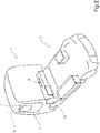
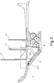
- the door 5 of the cabin used to have direct access to the driving position is movable with respect to the cabin 1 about a substantially vertical hinge axis A arranged, in use, between a closing position ( Figures 2 and 5 ), in which the door 5 closes the side opening 7, and an opening position ( Figures 1 , 4 and 3 ) in which the door 5 opens to allow access to the cabin through the side opening 7.
- the cabin 1 is provided with an extractable ladder 12 comprising a plurality of steps 14 (five in the example, but the number may obviously vary) moving between a retracted rest position, in which the steps 14 are housed in a seat 16 made in the cabin 1, and an extracted operating position, in which the steps 14 project from a side wall of the cabin.
- the extractable ladder 12 further comprises a top step 14-p arranged at an upper end of the ladder and being larger than the other steps.
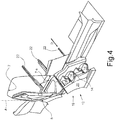
- the top step 14-p is arranged below a lower edge 7-s of the side opening ( Figure 4 ); in this way, when arranged in the operating position, the top step 14-p acts as a landing to allow access to the side opening 7.
- the extractable ladder 12 further comprises a side wall 20, which extends facing lower end sides of the steps 14.
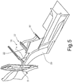
- the side wall 20 has, in plan view, shape and size corresponding to the shape and size of the opening ( Figure 2 ) with which the seat 16 communicates with the outside of the side wall of the cabin; said side wall 20 closes said opening of said seat when said ladder is arranged in said rest position and provides a side for the ladder when said ladder is arranged in said extracted operating position.
- the side wall 20 has, in plan view, an approximately trapezoidal shape.
- the ladder 12 comprises a supporting structure 19 for supporting said steps and side wall 20 made of tubular sections welded to each other by means of known techniques.
- the supporting structure 19 is movable along rectilinear guides 22, which are carried by the cabin 1 and extend along a direction D transverse to the side walls of the cabin 1 and to the longitudinal axis of the vehicle.
- a reversible actuator e.g. pneumatic, not shown
- moving the supporting structure 19 along the guides 22 to move the ladder 12 from the retracted rest position to the extracted operating position and vice versa, from the extracted operating position to the retracted rest position.
- the door 5 is provided with a straight guide 30, housed in a cavity formed in the body of the door, and with an end portion 30-a hinged to a vertical edge of the opening 7 to rotate about the vertical hinge axis A of the door 5.
- a slide is slidable along the guide 30 under the thrust of a first actuator (e.g. electric, not shown) with reversible linear motion.
- the slide is integral to the door, which is movable with reversible motion along the guide along the axis B.
- the movement of the first actuator controlling the movement of the door along the axis B is controlled during the movement of the door about the axis A so as to accomplish a rototranslating movement of the door that allows the door to move away from the side wall of the cabin while opening the door by rotating it about the axis A, and to move closer to the side wall of the cabin while closing the door by rotating it about the axis A.
- the movement of the door about the axis A is accomplished by a second actuator (not shown) controlled by an electronic control unit 35, which also controls the first actuator that accomplishes the movement of the door along the axis B so that after the complete opening of the door 5, i.e. when a maximum opening angle ⁇ MAX is reached, the door (5) is translated along the axis B.
- the electronic control unit 35 may control the first actuator that accomplishes the movement of the door along the axis B so that a predetermined position of the slide along the straight guide corresponds to each angular opening position ⁇ of the door about the axis A and with respect to the plane defined by the side wall of the cabin.
- the electronic control unit 35 also controls the actuators accomplishing the movement of the ladder 12 along the straight guides 22, so that the extractable ladder 12 is available in the extracted operating position when the door is in the open position and is available in the retracted rest position when the door is in the closing position.
- the movement of the ladder as it comes out of the seat 16 is synchronized with the opening movement of the door 5 and the movement of the ladder 12 as it re-enters the seat 16 is synchronized with the closing movement of the door 5.
Landscapes
- Engineering & Computer Science (AREA)
- Mechanical Engineering (AREA)
- Vehicle Step Arrangements And Article Storage (AREA)
- Ladders (AREA)
- Forklifts And Lifting Vehicles (AREA)
Description
- The present invention relates to a cabin for industrial vehicle provided with an extractable side ladder to allow access to the cabin.
- As already known, industrial vehicles are equipped with a cabin defined by a pair of vertical side walls, a horizontal base wall, a front wall housing a windshield, a rear wall and a substantially horizontal top wall. The cabin defines an approximately parallelepiped-shaped inner volume accessible through a pair of side openings arranged on the opposite sides of the cabin and formed on the side walls. The side openings are provided with doors hinged to the cabin and used to access a driving position and a passenger seat, respectively.
- Modern industrial vehicles are characterized by their large size, in particular their height. For this reason, the side openings have a lower side access edge that is very far away from the plane supporting the industrial vehicle.
- To allow access to the doors, industrial vehicles are equipped with seats opening on the portions of the cabin walls below the door; the base of these seats supports the foot of the vehicle's driver when he/she climbs into the cabin.
- For example, the patent
DE 10 2004 026 464 describes an industrial vehicle equipped with a raised cabin provided with a front wall and with two side walls, each of which is provided with a door. The access to the raised cabin is allowed by stairs formed by three overlapping steps extending from the side walls and bordered by curved sides. -
WO9840241 - The object of the present invention is to provide a cabin that allows easy access to the door.
- The foregoing object is achieved by the present invention as it relates to an industrial vehicle in which a cabin is provided with at least one side opening that can be used to allow access to the cabin, and with a door moving with respect to the cabin about a substantially vertical hinge axis A arranged, in use, between a closing position, in which said door closes said side opening, and an opening position allowing access to the cabin through said side opening, characterized in that it comprises: an extractable ladder comprising a plurality of steps moving between a retracted rest position, in which said steps are housed in a seat formed in the cabin, and an extracted operating position, in which the steps project from a side wall of the cabin; said extractable ladder further comprising a top step arranged at an upper end of the ladder and being larger than the other steps; said top step being arranged below a lower edge of the side opening; said top step, when arranged in the operating position, acting as a landing to allow access to said side opening. It is further provided a guide, coupled to said door and allowing the movement of said door along a horizontal axis B perpendicular to the axis A so as to accomplish a rototranslating movement of the door that allows the door to move away from the side wall of the cabin while opening the door about the axis A and to move closer to the side wall of the cabin while closing the door.
- The invention will now be illustrated with reference to the accompanying drawings representing a preferred embodiment thereof, wherein:
-
Figure 1 shows a schematic perspective view of an industrial vehicle provided with a cabin made in accordance with the requirements of the present invention and in a first operating position (opening position); -
Figure 2 shows a schematic perspective view of an industrial vehicle with a cabin made in accordance with the requirements of the present invention and in a second operating position (closing position); -
Figure 3 shows, in a top view, a detail of the cabin; -
Figure 4 shows a perspective view of the detail ofFigure 3 in the first operating position; and -
Figure 5 shows a perspective view of the detail ofFigure 3 in the second operating position. -
Figure 1 indicates with the reference number 1, as a whole, a cabin of an industrial vehicle 2 (schematically shown inFigures 1 and2 ). The known cabin 1 is defined by a pair of vertical side walls, a horizontal base wall, a front wall housing a windshield, a rear wall and a substantially horizontal top wall. The cabin 1 defines an approximately parallelepiped-shaped inner volume accessible through a pair of side openings 7 (only one being visible inFigures 1 and2 ) arranged on the opposite sides of the cabin 1 and formed on the side walls. - The
side openings 7 are provided withdoors 5 hinged to the cabin and used to have access to a driving position and to a passenger seat, respectively. As an alternative, there might be a single door to access the driving position. - The
door 5 of the cabin used to have direct access to the driving position is movable with respect to the cabin 1 about a substantially vertical hinge axis A arranged, in use, between a closing position (Figures 2 and5 ), in which thedoor 5 closes the side opening 7, and an opening position (Figures 1 ,4 and3 ) in which thedoor 5 opens to allow access to the cabin through the side opening 7. According to the present invention, the cabin 1 is provided with anextractable ladder 12 comprising a plurality of steps 14 (five in the example, but the number may obviously vary) moving between a retracted rest position, in which thesteps 14 are housed in aseat 16 made in the cabin 1, and an extracted operating position, in which thesteps 14 project from a side wall of the cabin. Theextractable ladder 12 further comprises a top step 14-p arranged at an upper end of the ladder and being larger than the other steps. The top step 14-p is arranged below a lower edge 7-s of the side opening (Figure 4 ); in this way, when arranged in the operating position, the top step 14-p acts as a landing to allow access to the side opening 7. - The
extractable ladder 12 further comprises aside wall 20, which extends facing lower end sides of thesteps 14. Theside wall 20 has, in plan view, shape and size corresponding to the shape and size of the opening (Figure 2 ) with which theseat 16 communicates with the outside of the side wall of the cabin; saidside wall 20 closes said opening of said seat when said ladder is arranged in said rest position and provides a side for the ladder when said ladder is arranged in said extracted operating position. - In the example shown, the
side wall 20 has, in plan view, an approximately trapezoidal shape. - In more detail, the
ladder 12 comprises a supportingstructure 19 for supporting said steps andside wall 20 made of tubular sections welded to each other by means of known techniques. The supportingstructure 19 is movable alongrectilinear guides 22, which are carried by the cabin 1 and extend along a direction D transverse to the side walls of the cabin 1 and to the longitudinal axis of the vehicle. It is further provided a reversible actuator (e.g. pneumatic, not shown) for moving the supportingstructure 19 along theguides 22 to move theladder 12 from the retracted rest position to the extracted operating position and vice versa, from the extracted operating position to the retracted rest position. - The
door 5 is provided with astraight guide 30, housed in a cavity formed in the body of the door, and with an end portion 30-a hinged to a vertical edge of theopening 7 to rotate about the vertical hinge axis A of thedoor 5. A slide is slidable along theguide 30 under the thrust of a first actuator (e.g. electric, not shown) with reversible linear motion. The slide is integral to the door, which is movable with reversible motion along the guide along the axis B. - The movement of the first actuator controlling the movement of the door along the axis B is controlled during the movement of the door about the axis A so as to accomplish a rototranslating movement of the door that allows the door to move away from the side wall of the cabin while opening the door by rotating it about the axis A, and to move closer to the side wall of the cabin while closing the door by rotating it about the axis A.
- Conveniently, the movement of the door about the axis A is accomplished by a second actuator (not shown) controlled by an electronic control unit 35, which also controls the first actuator that accomplishes the movement of the door along the axis B so that after the complete opening of the
door 5, i.e. when a maximum opening angle αMAX is reached, the door (5) is translated along the axis B. - Alternatively, the electronic control unit 35 may control the first actuator that accomplishes the movement of the door along the axis B so that a predetermined position of the slide along the straight guide corresponds to each angular opening position α of the door about the axis A and with respect to the plane defined by the side wall of the cabin.
- In both cases, when the
door 5 reaches the maximum opening angle αMAX, the front vertical edge of the door (the one facing the hinge axis A) has moved away from the side walls of a few centimetres; such displacement prevents any contact between the top step 14-p and thedoor 5 that is on one side of the top step 14-p. - The electronic control unit 35 also controls the actuators accomplishing the movement of the
ladder 12 along thestraight guides 22, so that theextractable ladder 12 is available in the extracted operating position when the door is in the open position and is available in the retracted rest position when the door is in the closing position. In more detail, the movement of the ladder as it comes out of theseat 16 is synchronized with the opening movement of thedoor 5 and the movement of theladder 12 as it re-enters theseat 16 is synchronized with the closing movement of thedoor 5.
Claims (9)
- An industrial vehicle wherein a cabin (1) is provided with at least one side opening (7) allowing access to the inside of the cabin, and with a door (5) moving with respect to the cabin about a substantially vertical hinge axis A arranged, in use, between a closing position, in which said door (5) closes said side opening (7), and an opening position allowing access to the cabin through said side opening (7),
the vehicle comprising
an extractable ladder (12) comprising a plurality of steps (14) moving between a retracted rest position, in which said steps (14) are housed in a seat (16) provided in the cabin, and an extracted operating position, in which the steps (14) project from a side wall of said cabin;
said extractable ladder further comprising a top step (14-p) arranged at an upper end of the ladder and being larger than the other steps (14); said top step (14-p) being arranged below a lower edge (7-s) of the side opening (7); said top step (14-p), when arranged in the operating position, acting as a landing to allow access to said side opening (7);
characterized in that a guide (30) is further provided, which is coupled to said door (5) and allows the movement of said door along a horizontal axis B perpendicular to the axis A so as to accomplish a rototranslating movement of the door, which allows the door to move away from the side wall of the cabin while opening the door about the axis A, and to move closer to the side wall of the cabin while closing the door. - A vehicle according to claim 1, wherein said extractable ladder (12) comprises a side wall (20), which extends facing shorter end sides of said steps (14), said side wall (20) having, in plan view, shape and size corresponding to the shape and size of the opening through which said seat (16) communicates with the outside of the side wall of the cabin; said side wall (20) closing said opening of said seat when said ladder is arranged in said rest position and providing a side for the ladder when said ladder (12) is arranged in said extracted operating position.
- A vehicle according to claim 2, wherein the side wall has, in plan view, an approximately trapezoidal shape.
- A vehicle according to claim 2 or 3, wherein said ladder comprises a supporting structure (19) for supporting said steps (14) and said side wall (20); said supporting structure (19) being movable with reversible motion under the thrust of actuators along rectilinear guides (22) which are carried by said cabin and extend in a direction (D) transverse to the side walls of said cabin (1) and to the longitudinal axis of said vehicle.
- A vehicle according to any one of the preceding claims, wherein said guide (30) is rectilinear, is housed in a cavity provided in the body of the door and is provided with an end portion (30-a) hinged to a vertical edge of the opening (7) to rotate about the vertical hinge axis A of the door (5); a slide slides along the guide under the thrust of first actuators with reversible linear motion; said slide is integral with the door, which is movable with reversible motion along the guide along the axis B.
- A vehicle according to claim 5, wherein electronic control means (35) are provided for controlling first actuators and second actuators accomplishing the angular movement of the door about the axis A; said electronic control means (35) control said first and second actuators so that each door opening angular position α about the axis A and with respect to the plane defined by the side wall of the cabin corresponds to a predefined position of the slide along the rectilinear guide.
- A vehicle according to claim 5, wherein electronic control means (35) are provided for controlling the first and second actuators accomplishing the door angular movement about the axis A; said electronic control means (35) control said first and second actuators so that after a complete opening of the door (5), when a maximum opening angle αMAX is reached, the door (5) is translated along the axis B.
- A vehicle according to any one of the preceding claims, wherein control means are provided that are designed to allow the movement of the ladder (12) with respect to the cabin so that the extractable ladder (12) is available in said extracted operating position when the door is in the opening position and is available in the retracted rest position when the door is in the closing position.
- A vehicle according to claim 8, wherein the movement of the ladder as it comes out of the seat is synchronized with the opening movement of the door and the movement of the ladder as it re-enters the seat is synchronized with the closing movement of the door.
Applications Claiming Priority (2)
| Application Number | Priority Date | Filing Date | Title |
|---|---|---|---|
| IT102016000093806A IT201600093806A1 (en) | 2016-09-19 | 2016-09-19 | GUIDE CABIN FOR INDUSTRIAL VEHICLE PROVIDED WITH REMOVABLE SIDE SCALE TO ENABLE ACCESS TO THE SAME CAB |
| PCT/IB2017/055674 WO2018051319A1 (en) | 2016-09-19 | 2017-09-19 | Cabin for industrial vehicle comprising an extractable side ladder to allow access to said cabin |
Publications (2)
| Publication Number | Publication Date |
|---|---|
| EP3515794A1 EP3515794A1 (en) | 2019-07-31 |
| EP3515794B1 true EP3515794B1 (en) | 2020-08-05 |
Family
ID=58159306
Family Applications (1)
| Application Number | Title | Priority Date | Filing Date |
|---|---|---|---|
| EP17787624.0A Active EP3515794B1 (en) | 2016-09-19 | 2017-09-19 | Cabin for industrial vehicle comprising an extractable side ladder to allow access to said cabin |
Country Status (4)
| Country | Link |
|---|---|
| EP (1) | EP3515794B1 (en) |
| ES (1) | ES2822651T3 (en) |
| IT (1) | IT201600093806A1 (en) |
| WO (1) | WO2018051319A1 (en) |
Families Citing this family (1)
| Publication number | Priority date | Publication date | Assignee | Title |
|---|---|---|---|---|
| IT201900022053A1 (en) * | 2019-11-25 | 2021-05-25 | Manitou Italia Srl | Access ladder for a vehicle. |
Family Cites Families (3)
| Publication number | Priority date | Publication date | Assignee | Title |
|---|---|---|---|---|
| JPH08332900A (en) * | 1995-06-08 | 1996-12-17 | Mitsubishi Motors Corp | Vehicle entry / exit step structure |
| US6179312B1 (en) * | 1997-03-14 | 2001-01-30 | Freightliner Llc | Retractable stairway for entering and exiting a vehicle |
| DE102010026256A1 (en) * | 2010-07-06 | 2011-03-03 | Daimler Ag | Lifting arrangement for mounting driving cab of lorry, has revolving door arranged above lifting unit, where rear end region of revolving door is supported at B-column of driving cab of motor vehicle |
-
2016
- 2016-09-19 IT IT102016000093806A patent/IT201600093806A1/en unknown
-
2017
- 2017-09-19 ES ES17787624T patent/ES2822651T3/en active Active
- 2017-09-19 WO PCT/IB2017/055674 patent/WO2018051319A1/en not_active Ceased
- 2017-09-19 EP EP17787624.0A patent/EP3515794B1/en active Active
Non-Patent Citations (1)
| Title |
|---|
| None * |
Also Published As
| Publication number | Publication date |
|---|---|
| WO2018051319A1 (en) | 2018-03-22 |
| EP3515794A1 (en) | 2019-07-31 |
| IT201600093806A1 (en) | 2018-03-19 |
| ES2822651T3 (en) | 2021-05-04 |
Similar Documents
| Publication | Publication Date | Title |
|---|---|---|
| EP1207067B1 (en) | Vehicle | |
| US8523278B2 (en) | Sliding roof device, in particular for a motor vehicle | |
| US11230170B2 (en) | Motor vehicle having an interior accessible via a door opening | |
| US9834075B2 (en) | Roof system for an automotive vehicle | |
| CN109515535A (en) | Adjustable vehicle body skirt assemblies and vehicle | |
| EP3446920B1 (en) | Vehicle furniture system | |
| CN103132874A (en) | Closure assembly with moveable cover and closeout for a retractable handle | |
| JP2022508456A (en) | Vehicle door system, its control method and the vehicle equipped with it | |
| EP3003947B1 (en) | Retractable toe guard assembly for an elevator system | |
| JP6159058B2 (en) | Sunroof device | |
| EP3515794B1 (en) | Cabin for industrial vehicle comprising an extractable side ladder to allow access to said cabin | |
| US10118562B2 (en) | Automatic sliding roof rail system | |
| US10988085B2 (en) | Motor vehicle | |
| GB2565109A (en) | Rear closure assembly | |
| KR102593228B1 (en) | Drone station | |
| JP6059881B2 (en) | Sunroof device | |
| US10907396B2 (en) | System for opening a tailgate having a plurality of opening kinematics | |
| EP1817191B1 (en) | Openable roof system for a motor car | |
| CN211677854U (en) | Lifting table cabinet system | |
| KR102633866B1 (en) | System for variable roof of vehicle | |
| CN106671749B (en) | Vehicle with a vehicle body having a vehicle body support | |
| JP4413654B2 (en) | Instrument panel for vehicle | |
| US20240198770A1 (en) | Openable Vehicle Roof Comprising a Cover | |
| EP1555002A1 (en) | Vehicle access ramp | |
| US11813927B2 (en) | Side structure for a passenger vehicle with a lowerable side window, and passenger vehicle |
Legal Events
| Date | Code | Title | Description |
|---|---|---|---|
| STAA | Information on the status of an ep patent application or granted ep patent |
Free format text: STATUS: UNKNOWN |
|
| STAA | Information on the status of an ep patent application or granted ep patent |
Free format text: STATUS: THE INTERNATIONAL PUBLICATION HAS BEEN MADE |
|
| PUAI | Public reference made under article 153(3) epc to a published international application that has entered the european phase |
Free format text: ORIGINAL CODE: 0009012 |
|
| STAA | Information on the status of an ep patent application or granted ep patent |
Free format text: STATUS: REQUEST FOR EXAMINATION WAS MADE |
|
| 17P | Request for examination filed |
Effective date: 20190313 |
|
| AK | Designated contracting states |
Kind code of ref document: A1 Designated state(s): AL AT BE BG CH CY CZ DE DK EE ES FI FR GB GR HR HU IE IS IT LI LT LU LV MC MK MT NL NO PL PT RO RS SE SI SK SM TR |
|
| AX | Request for extension of the european patent |
Extension state: BA ME |
|
| DAV | Request for validation of the european patent (deleted) | ||
| DAX | Request for extension of the european patent (deleted) | ||
| GRAP | Despatch of communication of intention to grant a patent |
Free format text: ORIGINAL CODE: EPIDOSNIGR1 |
|
| STAA | Information on the status of an ep patent application or granted ep patent |
Free format text: STATUS: GRANT OF PATENT IS INTENDED |
|
| INTG | Intention to grant announced |
Effective date: 20200228 |
|
| GRAS | Grant fee paid |
Free format text: ORIGINAL CODE: EPIDOSNIGR3 |
|
| GRAA | (expected) grant |
Free format text: ORIGINAL CODE: 0009210 |
|
| STAA | Information on the status of an ep patent application or granted ep patent |
Free format text: STATUS: THE PATENT HAS BEEN GRANTED |
|
| AK | Designated contracting states |
Kind code of ref document: B1 Designated state(s): AL AT BE BG CH CY CZ DE DK EE ES FI FR GB GR HR HU IE IS IT LI LT LU LV MC MK MT NL NO PL PT RO RS SE SI SK SM TR |
|
| REG | Reference to a national code |
Ref country code: GB Ref legal event code: FG4D |
|
| REG | Reference to a national code |
Ref country code: CH Ref legal event code: EP |
|
| REG | Reference to a national code |
Ref country code: AT Ref legal event code: REF Ref document number: 1298350 Country of ref document: AT Kind code of ref document: T Effective date: 20200815 |
|
| REG | Reference to a national code |
Ref country code: DE Ref legal event code: R096 Ref document number: 602017021243 Country of ref document: DE |
|
| REG | Reference to a national code |
Ref country code: IE Ref legal event code: FG4D |
|
| REG | Reference to a national code |
Ref country code: LT Ref legal event code: MG4D |
|
| REG | Reference to a national code |
Ref country code: NL Ref legal event code: MP Effective date: 20200805 |
|
| REG | Reference to a national code |
Ref country code: AT Ref legal event code: MK05 Ref document number: 1298350 Country of ref document: AT Kind code of ref document: T Effective date: 20200805 |
|
| PG25 | Lapsed in a contracting state [announced via postgrant information from national office to epo] |
Ref country code: FI Free format text: LAPSE BECAUSE OF FAILURE TO SUBMIT A TRANSLATION OF THE DESCRIPTION OR TO PAY THE FEE WITHIN THE PRESCRIBED TIME-LIMIT Effective date: 20200805 Ref country code: AT Free format text: LAPSE BECAUSE OF FAILURE TO SUBMIT A TRANSLATION OF THE DESCRIPTION OR TO PAY THE FEE WITHIN THE PRESCRIBED TIME-LIMIT Effective date: 20200805 Ref country code: LT Free format text: LAPSE BECAUSE OF FAILURE TO SUBMIT A TRANSLATION OF THE DESCRIPTION OR TO PAY THE FEE WITHIN THE PRESCRIBED TIME-LIMIT Effective date: 20200805 Ref country code: BG Free format text: LAPSE BECAUSE OF FAILURE TO SUBMIT A TRANSLATION OF THE DESCRIPTION OR TO PAY THE FEE WITHIN THE PRESCRIBED TIME-LIMIT Effective date: 20201105 Ref country code: PT Free format text: LAPSE BECAUSE OF FAILURE TO SUBMIT A TRANSLATION OF THE DESCRIPTION OR TO PAY THE FEE WITHIN THE PRESCRIBED TIME-LIMIT Effective date: 20201207 Ref country code: NO Free format text: LAPSE BECAUSE OF FAILURE TO SUBMIT A TRANSLATION OF THE DESCRIPTION OR TO PAY THE FEE WITHIN THE PRESCRIBED TIME-LIMIT Effective date: 20201105 Ref country code: GR Free format text: LAPSE BECAUSE OF FAILURE TO SUBMIT A TRANSLATION OF THE DESCRIPTION OR TO PAY THE FEE WITHIN THE PRESCRIBED TIME-LIMIT Effective date: 20201106 Ref country code: HR Free format text: LAPSE BECAUSE OF FAILURE TO SUBMIT A TRANSLATION OF THE DESCRIPTION OR TO PAY THE FEE WITHIN THE PRESCRIBED TIME-LIMIT Effective date: 20200805 Ref country code: SE Free format text: LAPSE BECAUSE OF FAILURE TO SUBMIT A TRANSLATION OF THE DESCRIPTION OR TO PAY THE FEE WITHIN THE PRESCRIBED TIME-LIMIT Effective date: 20200805 |
|
| PG25 | Lapsed in a contracting state [announced via postgrant information from national office to epo] |
Ref country code: PL Free format text: LAPSE BECAUSE OF FAILURE TO SUBMIT A TRANSLATION OF THE DESCRIPTION OR TO PAY THE FEE WITHIN THE PRESCRIBED TIME-LIMIT Effective date: 20200805 Ref country code: LV Free format text: LAPSE BECAUSE OF FAILURE TO SUBMIT A TRANSLATION OF THE DESCRIPTION OR TO PAY THE FEE WITHIN THE PRESCRIBED TIME-LIMIT Effective date: 20200805 Ref country code: RS Free format text: LAPSE BECAUSE OF FAILURE TO SUBMIT A TRANSLATION OF THE DESCRIPTION OR TO PAY THE FEE WITHIN THE PRESCRIBED TIME-LIMIT Effective date: 20200805 Ref country code: NL Free format text: LAPSE BECAUSE OF FAILURE TO SUBMIT A TRANSLATION OF THE DESCRIPTION OR TO PAY THE FEE WITHIN THE PRESCRIBED TIME-LIMIT Effective date: 20200805 Ref country code: IS Free format text: LAPSE BECAUSE OF FAILURE TO SUBMIT A TRANSLATION OF THE DESCRIPTION OR TO PAY THE FEE WITHIN THE PRESCRIBED TIME-LIMIT Effective date: 20201205 |
|
| PG25 | Lapsed in a contracting state [announced via postgrant information from national office to epo] |
Ref country code: SM Free format text: LAPSE BECAUSE OF FAILURE TO SUBMIT A TRANSLATION OF THE DESCRIPTION OR TO PAY THE FEE WITHIN THE PRESCRIBED TIME-LIMIT Effective date: 20200805 Ref country code: CZ Free format text: LAPSE BECAUSE OF FAILURE TO SUBMIT A TRANSLATION OF THE DESCRIPTION OR TO PAY THE FEE WITHIN THE PRESCRIBED TIME-LIMIT Effective date: 20200805 Ref country code: DK Free format text: LAPSE BECAUSE OF FAILURE TO SUBMIT A TRANSLATION OF THE DESCRIPTION OR TO PAY THE FEE WITHIN THE PRESCRIBED TIME-LIMIT Effective date: 20200805 Ref country code: RO Free format text: LAPSE BECAUSE OF FAILURE TO SUBMIT A TRANSLATION OF THE DESCRIPTION OR TO PAY THE FEE WITHIN THE PRESCRIBED TIME-LIMIT Effective date: 20200805 Ref country code: EE Free format text: LAPSE BECAUSE OF FAILURE TO SUBMIT A TRANSLATION OF THE DESCRIPTION OR TO PAY THE FEE WITHIN THE PRESCRIBED TIME-LIMIT Effective date: 20200805 |
|
| REG | Reference to a national code |
Ref country code: CH Ref legal event code: PL |
|
| REG | Reference to a national code |
Ref country code: ES Ref legal event code: FG2A Ref document number: 2822651 Country of ref document: ES Kind code of ref document: T3 Effective date: 20210504 |
|
| REG | Reference to a national code |
Ref country code: DE Ref legal event code: R097 Ref document number: 602017021243 Country of ref document: DE |
|
| PG25 | Lapsed in a contracting state [announced via postgrant information from national office to epo] |
Ref country code: AL Free format text: LAPSE BECAUSE OF FAILURE TO SUBMIT A TRANSLATION OF THE DESCRIPTION OR TO PAY THE FEE WITHIN THE PRESCRIBED TIME-LIMIT Effective date: 20200805 Ref country code: MC Free format text: LAPSE BECAUSE OF FAILURE TO SUBMIT A TRANSLATION OF THE DESCRIPTION OR TO PAY THE FEE WITHIN THE PRESCRIBED TIME-LIMIT Effective date: 20200805 |
|
| PLBE | No opposition filed within time limit |
Free format text: ORIGINAL CODE: 0009261 |
|
| STAA | Information on the status of an ep patent application or granted ep patent |
Free format text: STATUS: NO OPPOSITION FILED WITHIN TIME LIMIT |
|
| REG | Reference to a national code |
Ref country code: BE Ref legal event code: MM Effective date: 20200930 |
|
| PG25 | Lapsed in a contracting state [announced via postgrant information from national office to epo] |
Ref country code: LU Free format text: LAPSE BECAUSE OF NON-PAYMENT OF DUE FEES Effective date: 20200919 Ref country code: SK Free format text: LAPSE BECAUSE OF FAILURE TO SUBMIT A TRANSLATION OF THE DESCRIPTION OR TO PAY THE FEE WITHIN THE PRESCRIBED TIME-LIMIT Effective date: 20200805 |
|
| 26N | No opposition filed |
Effective date: 20210507 |
|
| PG25 | Lapsed in a contracting state [announced via postgrant information from national office to epo] |
Ref country code: SI Free format text: LAPSE BECAUSE OF FAILURE TO SUBMIT A TRANSLATION OF THE DESCRIPTION OR TO PAY THE FEE WITHIN THE PRESCRIBED TIME-LIMIT Effective date: 20200805 Ref country code: LI Free format text: LAPSE BECAUSE OF NON-PAYMENT OF DUE FEES Effective date: 20200930 Ref country code: IE Free format text: LAPSE BECAUSE OF NON-PAYMENT OF DUE FEES Effective date: 20200919 Ref country code: BE Free format text: LAPSE BECAUSE OF NON-PAYMENT OF DUE FEES Effective date: 20200930 Ref country code: CH Free format text: LAPSE BECAUSE OF NON-PAYMENT OF DUE FEES Effective date: 20200930 |
|
| PG25 | Lapsed in a contracting state [announced via postgrant information from national office to epo] |
Ref country code: TR Free format text: LAPSE BECAUSE OF FAILURE TO SUBMIT A TRANSLATION OF THE DESCRIPTION OR TO PAY THE FEE WITHIN THE PRESCRIBED TIME-LIMIT Effective date: 20200805 Ref country code: MT Free format text: LAPSE BECAUSE OF FAILURE TO SUBMIT A TRANSLATION OF THE DESCRIPTION OR TO PAY THE FEE WITHIN THE PRESCRIBED TIME-LIMIT Effective date: 20200805 Ref country code: CY Free format text: LAPSE BECAUSE OF FAILURE TO SUBMIT A TRANSLATION OF THE DESCRIPTION OR TO PAY THE FEE WITHIN THE PRESCRIBED TIME-LIMIT Effective date: 20200805 |
|
| PG25 | Lapsed in a contracting state [announced via postgrant information from national office to epo] |
Ref country code: MK Free format text: LAPSE BECAUSE OF FAILURE TO SUBMIT A TRANSLATION OF THE DESCRIPTION OR TO PAY THE FEE WITHIN THE PRESCRIBED TIME-LIMIT Effective date: 20200805 |
|
| P01 | Opt-out of the competence of the unified patent court (upc) registered |
Effective date: 20230523 |
|
| PGFP | Annual fee paid to national office [announced via postgrant information from national office to epo] |
Ref country code: DE Payment date: 20250926 Year of fee payment: 9 |
|
| PGFP | Annual fee paid to national office [announced via postgrant information from national office to epo] |
Ref country code: IT Payment date: 20250909 Year of fee payment: 9 |
|
| PGFP | Annual fee paid to national office [announced via postgrant information from national office to epo] |
Ref country code: GB Payment date: 20250923 Year of fee payment: 9 |
|
| PGFP | Annual fee paid to national office [announced via postgrant information from national office to epo] |
Ref country code: FR Payment date: 20250925 Year of fee payment: 9 |
|
| PGFP | Annual fee paid to national office [announced via postgrant information from national office to epo] |
Ref country code: ES Payment date: 20251015 Year of fee payment: 9 |