EP3515684B1 - Apparatus for cooling and handling preforms in plastic material - Google Patents
Apparatus for cooling and handling preforms in plastic material Download PDFInfo
- Publication number
- EP3515684B1 EP3515684B1 EP17784557.5A EP17784557A EP3515684B1 EP 3515684 B1 EP3515684 B1 EP 3515684B1 EP 17784557 A EP17784557 A EP 17784557A EP 3515684 B1 EP3515684 B1 EP 3515684B1
- Authority
- EP
- European Patent Office
- Prior art keywords
- cooling
- aspiration
- air
- duct
- handling station
- Prior art date
- Legal status (The legal status is an assumption and is not a legal conclusion. Google has not performed a legal analysis and makes no representation as to the accuracy of the status listed.)
- Active
Links
Images




Classifications
-
- B—PERFORMING OPERATIONS; TRANSPORTING
- B29—WORKING OF PLASTICS; WORKING OF SUBSTANCES IN A PLASTIC STATE IN GENERAL
- B29C—SHAPING OR JOINING OF PLASTICS; SHAPING OF MATERIAL IN A PLASTIC STATE, NOT OTHERWISE PROVIDED FOR; AFTER-TREATMENT OF THE SHAPED PRODUCTS, e.g. REPAIRING
- B29C49/00—Blow-moulding, i.e. blowing a preform or parison to a desired shape within a mould; Apparatus therefor
- B29C49/42—Component parts, details or accessories; Auxiliary operations
- B29C49/64—Heating or cooling preforms, parisons or blown articles
- B29C49/6409—Thermal conditioning of preforms
- B29C49/6427—Cooling of preforms
-
- B—PERFORMING OPERATIONS; TRANSPORTING
- B29—WORKING OF PLASTICS; WORKING OF SUBSTANCES IN A PLASTIC STATE IN GENERAL
- B29C—SHAPING OR JOINING OF PLASTICS; SHAPING OF MATERIAL IN A PLASTIC STATE, NOT OTHERWISE PROVIDED FOR; AFTER-TREATMENT OF THE SHAPED PRODUCTS, e.g. REPAIRING
- B29C45/00—Injection moulding, i.e. forcing the required volume of moulding material through a nozzle into a closed mould; Apparatus therefor
- B29C45/17—Component parts, details or accessories; Auxiliary operations
- B29C45/72—Heating or cooling
- B29C45/7207—Heating or cooling of the moulded articles
-
- B—PERFORMING OPERATIONS; TRANSPORTING
- B29—WORKING OF PLASTICS; WORKING OF SUBSTANCES IN A PLASTIC STATE IN GENERAL
- B29C—SHAPING OR JOINING OF PLASTICS; SHAPING OF MATERIAL IN A PLASTIC STATE, NOT OTHERWISE PROVIDED FOR; AFTER-TREATMENT OF THE SHAPED PRODUCTS, e.g. REPAIRING
- B29C49/00—Blow-moulding, i.e. blowing a preform or parison to a desired shape within a mould; Apparatus therefor
- B29C49/02—Combined blow-moulding and manufacture of the preform or the parison
- B29C49/06—Injection blow-moulding
-
- B—PERFORMING OPERATIONS; TRANSPORTING
- B60—VEHICLES IN GENERAL
- B60H—ARRANGEMENTS OF HEATING, COOLING, VENTILATING OR OTHER AIR-TREATING DEVICES SPECIALLY ADAPTED FOR PASSENGER OR GOODS SPACES OF VEHICLES
- B60H1/00—Heating, cooling or ventilating devices
- B60H1/00642—Control systems or circuits; Control members or indication devices for heating, cooling or ventilating devices
-
- F—MECHANICAL ENGINEERING; LIGHTING; HEATING; WEAPONS; BLASTING
- F27—FURNACES; KILNS; OVENS; RETORTS
- F27D—DETAILS OR ACCESSORIES OF FURNACES, KILNS, OVENS OR RETORTS, IN SO FAR AS THEY ARE OF KINDS OCCURRING IN MORE THAN ONE KIND OF FURNACE
- F27D17/00—Arrangements for using waste heat; Arrangements for using, or disposing of, waste gases
- F27D17/10—Arrangements for using waste heat
-
- B—PERFORMING OPERATIONS; TRANSPORTING
- B29—WORKING OF PLASTICS; WORKING OF SUBSTANCES IN A PLASTIC STATE IN GENERAL
- B29C—SHAPING OR JOINING OF PLASTICS; SHAPING OF MATERIAL IN A PLASTIC STATE, NOT OTHERWISE PROVIDED FOR; AFTER-TREATMENT OF THE SHAPED PRODUCTS, e.g. REPAIRING
- B29C45/00—Injection moulding, i.e. forcing the required volume of moulding material through a nozzle into a closed mould; Apparatus therefor
- B29C45/17—Component parts, details or accessories; Auxiliary operations
- B29C45/72—Heating or cooling
- B29C45/7207—Heating or cooling of the moulded articles
- B29C2045/7214—Preform carriers for cooling preforms
- B29C2045/7228—Preform carriers for cooling preforms turret-like
-
- B—PERFORMING OPERATIONS; TRANSPORTING
- B29—WORKING OF PLASTICS; WORKING OF SUBSTANCES IN A PLASTIC STATE IN GENERAL
- B29C—SHAPING OR JOINING OF PLASTICS; SHAPING OF MATERIAL IN A PLASTIC STATE, NOT OTHERWISE PROVIDED FOR; AFTER-TREATMENT OF THE SHAPED PRODUCTS, e.g. REPAIRING
- B29C45/00—Injection moulding, i.e. forcing the required volume of moulding material through a nozzle into a closed mould; Apparatus therefor
- B29C45/17—Component parts, details or accessories; Auxiliary operations
- B29C45/72—Heating or cooling
- B29C45/7207—Heating or cooling of the moulded articles
- B29C2045/7214—Preform carriers for cooling preforms
- B29C2045/725—Cooling circuits within the preform carriers
-
- B—PERFORMING OPERATIONS; TRANSPORTING
- B29—WORKING OF PLASTICS; WORKING OF SUBSTANCES IN A PLASTIC STATE IN GENERAL
- B29C—SHAPING OR JOINING OF PLASTICS; SHAPING OF MATERIAL IN A PLASTIC STATE, NOT OTHERWISE PROVIDED FOR; AFTER-TREATMENT OF THE SHAPED PRODUCTS, e.g. REPAIRING
- B29C45/00—Injection moulding, i.e. forcing the required volume of moulding material through a nozzle into a closed mould; Apparatus therefor
- B29C45/17—Component parts, details or accessories; Auxiliary operations
- B29C45/72—Heating or cooling
- B29C45/7207—Heating or cooling of the moulded articles
- B29C2045/7257—Cooling or heating pins with temperature adjustment enhancing surface structure
-
- B—PERFORMING OPERATIONS; TRANSPORTING
- B29—WORKING OF PLASTICS; WORKING OF SUBSTANCES IN A PLASTIC STATE IN GENERAL
- B29C—SHAPING OR JOINING OF PLASTICS; SHAPING OF MATERIAL IN A PLASTIC STATE, NOT OTHERWISE PROVIDED FOR; AFTER-TREATMENT OF THE SHAPED PRODUCTS, e.g. REPAIRING
- B29C49/00—Blow-moulding, i.e. blowing a preform or parison to a desired shape within a mould; Apparatus therefor
- B29C49/02—Combined blow-moulding and manufacture of the preform or the parison
- B29C2049/023—Combined blow-moulding and manufacture of the preform or the parison using inherent heat of the preform, i.e. 1 step blow moulding
-
- B—PERFORMING OPERATIONS; TRANSPORTING
- B29—WORKING OF PLASTICS; WORKING OF SUBSTANCES IN A PLASTIC STATE IN GENERAL
- B29C—SHAPING OR JOINING OF PLASTICS; SHAPING OF MATERIAL IN A PLASTIC STATE, NOT OTHERWISE PROVIDED FOR; AFTER-TREATMENT OF THE SHAPED PRODUCTS, e.g. REPAIRING
- B29C49/00—Blow-moulding, i.e. blowing a preform or parison to a desired shape within a mould; Apparatus therefor
- B29C49/42—Component parts, details or accessories; Auxiliary operations
- B29C49/64—Heating or cooling preforms, parisons or blown articles
- B29C49/6604—Thermal conditioning of the blown article
- B29C2049/6606—Cooling the article
-
- B—PERFORMING OPERATIONS; TRANSPORTING
- B29—WORKING OF PLASTICS; WORKING OF SUBSTANCES IN A PLASTIC STATE IN GENERAL
- B29C—SHAPING OR JOINING OF PLASTICS; SHAPING OF MATERIAL IN A PLASTIC STATE, NOT OTHERWISE PROVIDED FOR; AFTER-TREATMENT OF THE SHAPED PRODUCTS, e.g. REPAIRING
- B29C49/00—Blow-moulding, i.e. blowing a preform or parison to a desired shape within a mould; Apparatus therefor
- B29C49/42—Component parts, details or accessories; Auxiliary operations
- B29C49/64—Heating or cooling preforms, parisons or blown articles
- B29C49/6604—Thermal conditioning of the blown article
- B29C2049/6606—Cooling the article
- B29C2049/6676—Cooling the article the medium being oriented towards special areas of the blown article
- B29C2049/6692—Bottom area
-
- B—PERFORMING OPERATIONS; TRANSPORTING
- B29—WORKING OF PLASTICS; WORKING OF SUBSTANCES IN A PLASTIC STATE IN GENERAL
- B29C—SHAPING OR JOINING OF PLASTICS; SHAPING OF MATERIAL IN A PLASTIC STATE, NOT OTHERWISE PROVIDED FOR; AFTER-TREATMENT OF THE SHAPED PRODUCTS, e.g. REPAIRING
- B29C45/00—Injection moulding, i.e. forcing the required volume of moulding material through a nozzle into a closed mould; Apparatus therefor
- B29C45/17—Component parts, details or accessories; Auxiliary operations
- B29C45/40—Removing or ejecting moulded articles
- B29C45/42—Removing or ejecting moulded articles using means movable from outside the mould between mould parts, e.g. robots
- B29C45/4225—Take-off members or carriers for the moulded articles, e.g. grippers
-
- B—PERFORMING OPERATIONS; TRANSPORTING
- B29—WORKING OF PLASTICS; WORKING OF SUBSTANCES IN A PLASTIC STATE IN GENERAL
- B29C—SHAPING OR JOINING OF PLASTICS; SHAPING OF MATERIAL IN A PLASTIC STATE, NOT OTHERWISE PROVIDED FOR; AFTER-TREATMENT OF THE SHAPED PRODUCTS, e.g. REPAIRING
- B29C49/00—Blow-moulding, i.e. blowing a preform or parison to a desired shape within a mould; Apparatus therefor
- B29C49/42—Component parts, details or accessories; Auxiliary operations
- B29C49/64—Heating or cooling preforms, parisons or blown articles
- B29C49/6409—Thermal conditioning of preforms
- B29C49/6427—Cooling of preforms
- B29C49/643—Cooling of preforms from the inside
-
- B—PERFORMING OPERATIONS; TRANSPORTING
- B29—WORKING OF PLASTICS; WORKING OF SUBSTANCES IN A PLASTIC STATE IN GENERAL
- B29C—SHAPING OR JOINING OF PLASTICS; SHAPING OF MATERIAL IN A PLASTIC STATE, NOT OTHERWISE PROVIDED FOR; AFTER-TREATMENT OF THE SHAPED PRODUCTS, e.g. REPAIRING
- B29C49/00—Blow-moulding, i.e. blowing a preform or parison to a desired shape within a mould; Apparatus therefor
- B29C49/42—Component parts, details or accessories; Auxiliary operations
- B29C49/64—Heating or cooling preforms, parisons or blown articles
- B29C49/6409—Thermal conditioning of preforms
- B29C49/6427—Cooling of preforms
- B29C49/6435—Cooling of preforms from the outside
-
- B—PERFORMING OPERATIONS; TRANSPORTING
- B29—WORKING OF PLASTICS; WORKING OF SUBSTANCES IN A PLASTIC STATE IN GENERAL
- B29K—INDEXING SCHEME ASSOCIATED WITH SUBCLASSES B29B, B29C OR B29D, RELATING TO MOULDING MATERIALS OR TO MATERIALS FOR MOULDS, REINFORCEMENTS, FILLERS OR PREFORMED PARTS, e.g. INSERTS
- B29K2101/00—Use of unspecified macromolecular compounds as moulding material
- B29K2101/12—Thermoplastic materials
-
- B—PERFORMING OPERATIONS; TRANSPORTING
- B29—WORKING OF PLASTICS; WORKING OF SUBSTANCES IN A PLASTIC STATE IN GENERAL
- B29L—INDEXING SCHEME ASSOCIATED WITH SUBCLASS B29C, RELATING TO PARTICULAR ARTICLES
- B29L2031/00—Other particular articles
- B29L2031/712—Containers; Packaging elements or accessories, Packages
- B29L2031/7158—Bottles
-
- B—PERFORMING OPERATIONS; TRANSPORTING
- B60—VEHICLES IN GENERAL
- B60H—ARRANGEMENTS OF HEATING, COOLING, VENTILATING OR OTHER AIR-TREATING DEVICES SPECIALLY ADAPTED FOR PASSENGER OR GOODS SPACES OF VEHICLES
- B60H1/00—Heating, cooling or ventilating devices
- B60H1/32—Cooling devices
- B60H2001/3286—Constructional features
- B60H2001/3291—Locations with heat exchange within the refrigerant circuit itself
-
- B—PERFORMING OPERATIONS; TRANSPORTING
- B60—VEHICLES IN GENERAL
- B60H—ARRANGEMENTS OF HEATING, COOLING, VENTILATING OR OTHER AIR-TREATING DEVICES SPECIALLY ADAPTED FOR PASSENGER OR GOODS SPACES OF VEHICLES
- B60H1/00—Heating, cooling or ventilating devices
- B60H1/32—Cooling devices
- B60H2001/3286—Constructional features
- B60H2001/3298—Ejector-type refrigerant circuits
-
- F—MECHANICAL ENGINEERING; LIGHTING; HEATING; WEAPONS; BLASTING
- F25—REFRIGERATION OR COOLING; COMBINED HEATING AND REFRIGERATION SYSTEMS; HEAT PUMP SYSTEMS; MANUFACTURE OR STORAGE OF ICE; LIQUEFACTION SOLIDIFICATION OF GASES
- F25B—REFRIGERATION MACHINES, PLANTS OR SYSTEMS; COMBINED HEATING AND REFRIGERATION SYSTEMS; HEAT PUMP SYSTEMS
- F25B2309/00—Gas cycle refrigeration machines
- F25B2309/006—Gas cycle refrigeration machines using a distributing valve of the rotary type
Definitions
- the present invention relates to an apparatus for cooling and handling preforms in plastic material, suitable, in particular, both for completing the cooling of preforms just molded and extracted from an injection mold by means of a plate or take-out device, and for extracting preforms cooled by said take-out device or by another intermediate retaining device.
- Such preforms are destined to be subsequently converted into containers, in particular, bottles or jars, by means of a blow-molding or stretch blow-molding process.
- the present invention also relates to an injection molding machine which includes said apparatus and to a relative process for handling and cooling preforms.
- Documents WO00/29193A1 , DE19848837A1 and US2014/255535A1 are illustrative of the technological background.
- Preforms are semi-finished products made of thermoplastic material, used for the manufacturing of containers obtained, in turn, by means of a subsequent blow-molding or stretch blow-molding process. Preforms are obtained by means of different processes, for example, by means of injection molding, injection-compression molding or extrusion combined with further hot forming operations. In the production of containers made of plastic material, such as, for example, bottles, preforms are typically obtained by means of injection molding with molds provided with a plurality of molding cavities.
- the step that involves the major time expenditure of most injection molding processes is the step of cooling the molded items.
- Said cooling step occurs inside the mold, and more precisely inside the molding cavities, until the molded items are not sufficiently rigid to be extracted from the mold itself and, subsequently, handled and transported.
- the molded items are not sufficiently cooled, and thus solidified, it will not be possible to free the mold cavities and continue the production cycle with a new molding step. Therefore, to reduce the time of an entire molding cycle, and thus increase the productivity of the molding station, different devices have been developed capable of performing at least one part of the cooling of the preforms outside the injection mold.
- Such withdrawing systems generally comprise a preform extraction plate, suitable for extracting the preforms from the injection mold and, at the same time, cooling them for a predetermined time, and this by means of the circulation of suitable fluids inside the extraction plate itself.
- Such extraction plate also known as a “post-mold device” or “take-out plate” or “end-of-arm tool” (EOAT)
- EOAT end-of-arm tool
- a plurality of cooling housings also known as shorts, but also known as “cooling tubes”, “take-out tubes” or “cooling sleeves”.
- At least one further cooling and handling apparatus is provided, cooperating upstream with said extraction plate and downstream with other components of the production plant.
- cooling and handling apparatuses of the prior art are not very efficient. Some of them, for the further cooling, use air aspirated from the inside of the injection molding machine casing. Therefore, the air used for this cooling is quite hot, usually at a temperature of 30-35°C, not ensuring optimal cooling.
- a known example of such apparatuses uses a rotatable handling station, also known as "rotary shell", which exclusively works by aspirating, both for the cooling step and for the step of retaining and extracting the preforms from the extraction plate.
- Working by aspirating in the further preforms cooling step involves that the hot air of the casing is aspirated directly inside the preforms to then pass inside the "rotary shell" after going through the respective pin of the rotatable handling station.
- the cooling and handling apparatuses of the prior art do not allow to meet the current market needs that require further optimization of the preforms cooling times and, hence, the injection molding cycle time, while ensuring the high quality of the preforms for the perfect molding of the blown-molded containers. Therefore, the need to achieve a preforms cooling and handling apparatus allowing to overcome the aforesaid drawbacks is felt.
- Another object of the invention is to achieve a more efficient process for cooling and handling preforms by means of an injection molding machine which includes the aforesaid apparatus.
- the present invention aims at meeting the above mentioned objects providing an apparatus for cooling and handling plastic preforms which comprises a rotatable handling station, provided with a plurality of pins for retaining and cooling preforms and adapted to cooperate with an extraction plate adapted to extract the preforms from an injection mold; an aeraulic circuit connected to said rotatable handling station; wherein said aeraulic circuit comprises
- Another aspect of the invention relates to an injection molding machine which comprises a casing inside of which there are provided
- a further aspect of the invention relates to a process for handling and cooling plastic preforms preformed in the aforesaid injection molding machine, the process comprising the following steps:
- said aspiration means consist of a single aspiration means, such as, for example, a fan or a blower or a vacuum pump, interposed between the aspiration duct and the delivery duct of the aeraulic circuit of the apparatus.
- Such single aspiration means is designed, in a first operation mode, for aspirating air from the inside of the casing of the machine, to be sent in the delivery duct and then, after the cooling by means of the cooling means, for example a heat exchanger or another suitable cooling means, inside the rotatable handling station or "rotary shell"; while, in a second operation mode, the single aspiration means is designed for aspirating air from the inside of the rotatable handling station, to be sent in the delivery duct which releases the air, after having cooled it by means of the cooling means, inside the casing itself.
- the cooling means for example a heat exchanger or another suitable cooling means
- the at least one valve associated to the rotatable handling station employs the same aspiration means both for the aspiration and for the delivery.
- the cooling of the preforms occurs by blowing, whereas the extraction occurs by aspirating.
- a better heat exchange is obtained by taking advantage of the delivery curve of the fan or of the blower, and not of that of the aspiration, which is 10-20% greater (shifted towards the top on the Cartesian plane Q [m 3 /h] - p [Pa]).
- the extraction force remains unchanged.
- a second advantageous embodiment of the invention provides, instead, a first aspiration means at an end of the aspiration duct and a second aspiration means at an end of the delivery duct.
- the first aspiration means is designed, in a first operation mode, for aspirating air from the inside of the casing of the machine, to be simply sent back in the casing; while, in a second operation mode, it is designed for aspirating air from the inside of the rotatable handling station, to be sent back in the casing.
- the second aspiration means instead, is designed, in said first operation mode, for aspirating air from the inside of the casing to be sent in the delivery duct and then, after the cooling by means of the cooling means, inside the rotatable handling station; whereas, in said second operation mode, it is designed for aspirating air from the inside of the casing, to be simply sent back in the casing after having cooled it by means of the cooling means.
- Said cooling means for example a heat exchanger of the air-water type, allow to cool the air at a temperature of preferably about 10-15 °C.
- an injection molding machine comprising the apparatus for cooling and handling preforms in accordance with the invention.
- Such injection molding machine 20 comprises a casing 21 inside of which there are provided at least:
- the cooling housings 13, of a more or less tubular or anyways hollow shape, are fastened on a suitable support frame or skeleton of the extraction plate 4, aligned in accordance with two directions of the space, and ordered in rows and columns so as to form a matrix.
- a seat with a geometry that reproduces the shape of the outer surface of the preform. Inside each seat, through an insertion opening, a preform to be cooled can be introduced.
- the interior space of the frame and of the cooling housings 13 is crossed by a cooling fluid, for example water and/or air, so as to cool the preforms inserted into said housings.
- a cooling fluid for example water and/or air
- a plurality of channels inside both the extraction plate and the housings allows the cooling fluid to run through a suitable route so as to touch and cool the various tubular bodies of the cooling housings.
- thermoplastic material such as PET, PEN, PP, PLA or other further and suitable material, as well as mixtures thereof, by means of subsequent blow molding or stretch blow-molding of preheated preforms.
- Such apparatus 1 for cooling and handling preforms comprises:
- the retaining and cooling pins 3 are fastened on the face 14 of the rotatable handling station 2, aligned in accordance with two directions in the space, and ordered in rows and columns so as to form a matrix, corresponding to the matrix of the cooling housings 13 on the extraction plate 4.
- Said pins 3 are communicating with an internal volume of the rotatable handling station 2, in turn communicating with the aeraulic circuit 5.
- the aeraulic circuit 5 comprises:
- the internal volume of the rotatable handling station 2 is defined by a single volume or space, communicating on one side with the aeraulic circuit 5 and on the other side with all the pins 3. From the side of the aunterlic circuit 5 the air can only be introduced in said single volume by means of the delivery duct 7, which is outside of the rotatable handling station 2, with consequent air blowing through all of the pins 3; or the air can be only aspirated by said single volume by means of the aspiration duct 6, which is also outside of the rotatable handling station 2, this aspiration determining the air passage from all of the pins 3 to the internal volume.
- cooling means are provided, for example a heat exchanger 8, arranged along the delivery duct 7 to cool the air sent to the rotatable handling station 2.
- a further advantage is given by the fact that switching means of the a somehowlic circuit are provided for, to pass from a first circuit configuration, in which there is an air passage from the delivery duct 7 to the inside of the rotatable handling station 2, to a second circuit configuration, in which there is an air passage from the inside of the rotatable handling station 2 to the aspiration duct 6, whereby, in the first circuit configuration, air can be blown through all the pins of the plurality of retaining and cooling pins 3, while, in the second circuit configuration, air can be aspirated through all the pins of said plurality of pins 3.
- Said switching means of the a Vogellic circuit comprise at least one valve 10, 30, 31 and actuating means 11 adapted to actuate said at least one valve.
- the actuating means 11 which actuate the at least one valve 10, 30, 31 are independent from the actuating means 12 ( Figure 9 ) which actuate the rotation of the rotatable handling station 2, allowing to select the blowing or aspirating mode independently of the position and of the movement of the rotatable handling station 2.
- the rotatable handling station 2 is configured, in turn, to rotate from a loading position for cooperating with the extraction plate 4 to an unloading position for releasing the preforms from said retaining and cooling pins 3.
- the face 14 is arranged parallel to the extraction plate 4 and the retaining and cooling pins 3 are adapted to cooperate with respective cooling housings 13.
- the pins 3 are inserted in the preforms arranged in the cooling housings 13 to perform, in an air blowing step when the aeraulic circuit is in the first circuit configuration, a second cooling of the preforms, and then to retain and extract the preforms from said cooling housings 13 in a step of aspirating air when the a Vogellic circuit is in the second circuit configuration.
- the aspiration means are adapted to aspirate air from the internal environment, or internal space, of the casing 21 in the first circuit configuration, while they are adapted to aspirate air from the inside of the rotatable handling station 2 in the second circuit configuration.
- a first embodiment of the apparatus in accordance with the invention provides for only one valve 10, for example a rotatable valve or a linear movement valve, associated with the rotatable handling station 2 and configured so as to pass from a first position, in which the valve 10 allows the air passage from the delivery duct 7 to the inside of the rotatable handling station 2, to a second position, in which the valve 10 allows the air passage from the inside of the rotatable handling station 2 to the aspiration duct 6, whereby, in the first position, air can be blown through the plurality of retaining and cooling pins 3, while, in the second position, air can be aspirated through said plurality of pins 3.
- a first position in which the valve 10 allows the air passage from the delivery duct 7 to the inside of the rotatable handling station 2
- a second position in which the valve 10 allows the air passage from the inside of the rotatable handling station 2 to the aspiration duct 6, whereby, in the first position, air can be blown through the plurality of retaining and cooling
- the valve 10 is connected to the shell of the rotatable handling station 2 and respective ends of the delivery duct 7 and of the aspiration duct 6 are connected thereto, i.e. to the valve 10.
- a rotatable valve 10 is shown, for example, in Figures 8 , 12a and 12b .
- the body of the rotatable valve 10 comprises two ducts: one duct 40 defining a first rectilinear axis, and one duct 41 comprising two segments 42, 43 connected by a curved segment 44, e.g. an L-pipe.
- Duct 40 and duct 41 are independent from one another, i.e. they are not communicating.
- the segment 42 defines a respective second rectilinear axis and the segment 43 defines a respective third rectilinear axis, second axis and third axis being substantially orthogonal to one another and also with respect to the first axis of the duct 40.
- the aspiration means 9 are interposed between the aspiration duct 6 and the delivery duct 7 so as to aspirate air from the aspiration duct 6 and to introduce it into the delivery duct 7. Aspiration duct 6 and delivery duct 7 are therefore in communication by means of said aspiration means 9.
- the aspiration means 9 may consist of a single fan or blower configured to aspirate air from the internal environment of the casing 21 when the valve 10 is in the first position, while is adapted to aspirate air from the inside of the rotatable handling station 2 when the valve 10 is in the second position.
- the aspiration means 9 preferably have a flow rate of at least 15 m 3 /min, more preferably from 15 to 80 m 3 /min, even more preferably from 60 to 80 m 3 /min, to avoid the collapse of the vacuum inside the rotary shell 2, in particular when, during the coupling of the face 14 and the extraction plate 4, some columns of cooling housings 13 are empty and do not contain preforms therewithin.
- first aspiration means 19 are provided at an end of the aspiration duct 6 and second aspiration means 29 are provided at an end of the delivery duct 7, said ends being distal from the rotatable handling station 2.
- the first aspiration means 19 can consist of a first fan or blower configured to aspirate air from the internal environment of the casing 21 when the valve 10 is in the first position, while is adapted to aspirate air from the inside of the rotatable handling station 2 when the valve 10 is in the second position.
- the second aspiration means 29 can consist of a second fan or blower, configured to aspirate air from the internal environment of the casing 21 to send it in the delivery duct 7, and subsequently to the rotatable handling station 2 when the valve 10 is in the first position, or again in the internal environment of the casing 21 after cooling, by means of the cooling means 8, the aspirated air.
- the first fan as the fan of the first variant, has a flow rate of at least 15 m 3 /min, preferably from 15 to 80 m 3 /min, even more preferably from 60 to 80 m 3 /min; while the second fan 29 has a flow rate of preferably about 15-200 m 3 /min, more preferably from 60 to 200 m 3 /min.
- the process for handling and cooling plastic preforms in the injection molding machine described above, considering the first embodiment of the invention, including its two variants, comprises the following steps:
- a second embodiment of the apparatus in accordance with the invention provides instead for at least two valves: a valve 30 is arranged in the delivery duct 7 downstream the cooling means 8, and a valve 31 is arranged in the aspiration duct 6 upstream the aspiration means 9.
- the actuating means 11 are adapted to open alternatively the valve 30 and the valve 31, whereby, when the valve 30 is open, the valve 31 is closed ( Figure 10b ) and the air passage is permitted from the delivery duct 7 to the inside of the rotatable handling station 2 (blowing step for cooling the preforms), while when the valve 31 is open, the valve 30 is closed ( Figure 10a ) and the air passage is permitted from the inside of the rotatable handling station 2 to the aspiration duct 6 (aspirating step for retaining the preforms on the station 2).
- the aspiration means 9 are interposed between the aspiration duct 6 and the delivery duct 7 so as to aspirate air from the aspiration duct 6 and to introduce it into the delivery duct 7. Aspiration duct 6 and delivery duct 7 are therefore in communication by means of said aspiration means 9.
- the aspiration means 9 may consist of only one fan or blower configured to aspirate air from the internal environment of the casing 21 when the valve 31 is in the position of Figure 10b , while is adapted to aspirate air from the inside of the rotatable handling station 2 when the valve 31 is in the position of Figures 10a .
- the aspiration means 9 preferably have a flow rate of at least 15 m 3 /min, more preferably from 15 to 80 m 3 /min, even more preferably from 60 to 80 m 3 /min, to avoid the collapse of the vacuum inside the rotary shell 2, in particular when, during the coupling of the face 14 and the extraction plate 4, some columns of cooling housings 13 are empty and do not contain preforms therewithin.
- a second variant can be provided, shown in Figures 11a and 11b , wherein the aspiration duct 6 and the delivery duct 7 are not communicating, and first aspiration means 19 are provided at an end of the aspiration duct 6 and second aspiration means 29 are provided at an end of the delivery duct 7, said ends being distal from the rotatable handling station 2.
- the first aspiration means 19 may consist of a first fan or blower configured to aspirate air from the internal environment of the casing 21 when the valve 31 assumes the position of Figure 11b , while is adapted to aspirate air from the inside of the rotatable handling station 2 when the valve 31 assumes the position of Figure 11a .
- the second aspiration means 29 may consist of a second fan or blower, configured to aspirate air from the internal environment of the casing 21 to send it in the delivery duct 7, and, subsequently, to the rotatable handling station 2 when the valve 30 assumes the position of Figure 11b , or in the internal environment of the casing 21 itself, after cooling the air aspirated by means of the cooling means 8, when the valve 30 assumes the position of Figure 11a .
- the first fan as the fan of the first variation, preferably has a flow rate of at least 15 m 3 /min, more preferably from 15 to 80 m 3 /min, even more preferably from 60 to 80 m 3 /min; while the second fan preferably has a flow rate of approximately 15-200 m 3 /min, more preferably from 60 to 200 m 3 /min.
Landscapes
- Engineering & Computer Science (AREA)
- Mechanical Engineering (AREA)
- Manufacturing & Machinery (AREA)
- Physics & Mathematics (AREA)
- Thermal Sciences (AREA)
- Environmental & Geological Engineering (AREA)
- General Engineering & Computer Science (AREA)
- Robotics (AREA)
- Blow-Moulding Or Thermoforming Of Plastics Or The Like (AREA)
- Moulds For Moulding Plastics Or The Like (AREA)
- Processing And Handling Of Plastics And Other Materials For Molding In General (AREA)
- Injection Moulding Of Plastics Or The Like (AREA)
Description
- The present invention relates to an apparatus for cooling and handling preforms in plastic material, suitable, in particular, both for completing the cooling of preforms just molded and extracted from an injection mold by means of a plate or take-out device, and for extracting preforms cooled by said take-out device or by another intermediate retaining device. Such preforms are destined to be subsequently converted into containers, in particular, bottles or jars, by means of a blow-molding or stretch blow-molding process. The present invention also relates to an injection molding machine which includes said apparatus and to a relative process for handling and cooling preforms. Documents
WO00/29193A1 DE19848837A1 andUS2014/255535A1 are illustrative of the technological background. - Preforms are semi-finished products made of thermoplastic material, used for the manufacturing of containers obtained, in turn, by means of a subsequent blow-molding or stretch blow-molding process. Preforms are obtained by means of different processes, for example, by means of injection molding, injection-compression molding or extrusion combined with further hot forming operations. In the production of containers made of plastic material, such as, for example, bottles, preforms are typically obtained by means of injection molding with molds provided with a plurality of molding cavities.
- Generally, the step that involves the major time expenditure of most injection molding processes is the step of cooling the molded items. Said cooling step occurs inside the mold, and more precisely inside the molding cavities, until the molded items are not sufficiently rigid to be extracted from the mold itself and, subsequently, handled and transported. Clearly, until the molded items are not sufficiently cooled, and thus solidified, it will not be possible to free the mold cavities and continue the production cycle with a new molding step. Therefore, to reduce the time of an entire molding cycle, and thus increase the productivity of the molding station, different devices have been developed capable of performing at least one part of the cooling of the preforms outside the injection mold.
- The systems for withdrawing preforms from injection molds are now provided with a cooling circuit. Said cooling circuit allows to decrease the production cycle time as already described above; indeed, if the withdrawing system is equipped with a cooling circuit, it is possible to reduce the time the preforms are to be kept inside the injection mold. Such withdrawing systems generally comprise a preform extraction plate, suitable for extracting the preforms from the injection mold and, at the same time, cooling them for a predetermined time, and this by means of the circulation of suitable fluids inside the extraction plate itself.
- Such extraction plate, also known as a "post-mold device" or "take-out plate" or "end-of-arm tool" (EOAT), is provided with a plurality of cooling housings, also known as shorts, but also known as "cooling tubes", "take-out tubes" or "cooling sleeves".
- Whatever the method and the device for the extraction from the injection mold, the cooling of the molded preforms, started in the molding cavities of the mold, continues in the extraction plate cooling housings.
- Downstream of the extraction plate, at least one further cooling and handling apparatus is provided, cooperating upstream with said extraction plate and downstream with other components of the production plant.
- However, the cooling and handling apparatuses of the prior art are not very efficient. Some of them, for the further cooling, use air aspirated from the inside of the injection molding machine casing. Therefore, the air used for this cooling is quite hot, usually at a temperature of 30-35°C, not ensuring optimal cooling. A known example of such apparatuses uses a rotatable handling station, also known as "rotary shell", which exclusively works by aspirating, both for the cooling step and for the step of retaining and extracting the preforms from the extraction plate. Working by aspirating in the further preforms cooling step involves that the hot air of the casing is aspirated directly inside the preforms to then pass inside the "rotary shell" after going through the respective pin of the rotatable handling station.
- Therefore, the cooling and handling apparatuses of the prior art do not allow to meet the current market needs that require further optimization of the preforms cooling times and, hence, the injection molding cycle time, while ensuring the high quality of the preforms for the perfect molding of the blown-molded containers. Therefore, the need to achieve a preforms cooling and handling apparatus allowing to overcome the aforesaid drawbacks is felt.
- It is a major object of the present invention to achieve a preforms cooling and handling apparatus which allows for a more efficient cooling with respect to the known apparatuses.
- Another object of the invention is to achieve a more efficient process for cooling and handling preforms by means of an injection molding machine which includes the aforesaid apparatus.
- The present invention, therefore, aims at meeting the above mentioned objects providing an apparatus for cooling and handling plastic preforms which comprises a rotatable handling station, provided with a plurality of pins for retaining and cooling preforms and adapted to cooperate with an extraction plate adapted to extract the preforms from an injection mold;
an aeraulic circuit connected to said rotatable handling station;
wherein said aeraulic circuit comprises - an aspiration duct for aspirating air from the inside of the rotatable handling station;
- a delivery duct for sending air to said rotatable handling station;
- cooling means arranged along said delivery duct for cooling the air sent to said rotatable handling station;
- aspiration means connected to said aspiration duct and to said delivery duct, and wherein switching means of the aeraulic circuit are further provided, to pass from a first aeraulic circuit configuration, in which an air passage is possible from the delivery duct to the rotatable handling station, to a second aeraulic circuit configuration, in which an air passage is possible from the rotatable handling station to the aspiration duct, whereby, in the first aeraulic circuit configuration, air can be blown by means of the plurality of retaining and cooling pins, while, in the second aeraulic circuit configuration, air can be aspirated by means of said plurality of retaining and cooling pins.
- Another aspect of the invention relates to an injection molding machine which comprises a casing inside of which there are provided
- at least one injection mold comprising a plurality of molding cavities;
- at least one extraction plate comprising at least one set of cooling housings, adapted to receive and retain at least one set of preforms extracted from said molding cavities; said cooling housings being adapted to remove by conduction a first amount of thermal energy from said preforms;
- and the aforesaid handling and cooling apparatus;
- A further aspect of the invention relates to a process for handling and cooling plastic preforms preformed in the aforesaid injection molding machine, the process comprising the following steps:
- providing the rotatable handling station in the loading position, arranged facing the extraction plate containing at least one set of preforms in the respective cooling housings, and providing the aeraulic circuit in said first aeraulic circuit configuration;
- inserting the retaining and cooling pins of the rotatable handling station in the respective cooling housings and further cooling the preforms contained in the latter by means of blowing air through said pins;
- switching the aeraulic circuit, by means of said switching means, from said first aeraulic circuit configuration to said second aeraulic circuit configuration and aspirating air through the pins to retain the preforms on the rotatable handling station;
- disengaging the retaining and cooling pins from the respective cooling housings continuing to aspirate air through the pins;
- rotating the rotatable handling station to pass from said loading position to an unloading position continuing to aspirate air through the pins;
- switching the aeraulic circuit, by means of said switching means, from said second aeraulic circuit configuration to said first aeraulic circuit configuration and blowing air through the pins to release the preforms from said pins. Advantageously, the apparatus of the invention allows, by virtue of the integration of blowing and aspirating possibilities, to obtain:
- both a more efficient cooling of the preforms, performed by means of blowing, by virtue of a better thermal exchange;
- and a greater efficiency also in the extraction step, performed by means of aspirating, ensuring an aspirating flow rate which avoids any risk of the preforms falling, once extracted from the extraction plate.
- In a first advantageous embodiment of the invention, said aspiration means consist of a single aspiration means, such as, for example, a fan or a blower or a vacuum pump, interposed between the aspiration duct and the delivery duct of the aeraulic circuit of the apparatus. Such single aspiration means is designed, in a first operation mode, for aspirating air from the inside of the casing of the machine, to be sent in the delivery duct and then, after the cooling by means of the cooling means, for example a heat exchanger or another suitable cooling means, inside the rotatable handling station or "rotary shell"; while, in a second operation mode, the single aspiration means is designed for aspirating air from the inside of the rotatable handling station, to be sent in the delivery duct which releases the air, after having cooled it by means of the cooling means, inside the casing itself.
- The at least one valve associated to the rotatable handling station employs the same aspiration means both for the aspiration and for the delivery. The cooling of the preforms occurs by blowing, whereas the extraction occurs by aspirating. A better heat exchange is obtained by taking advantage of the delivery curve of the fan or of the blower, and not of that of the aspiration, which is 10-20% greater (shifted towards the top on the Cartesian plane Q [m3/h] - p [Pa]). The extraction force remains unchanged.
- A second advantageous embodiment of the invention provides, instead, a first aspiration means at an end of the aspiration duct and a second aspiration means at an end of the delivery duct. The first aspiration means is designed, in a first operation mode, for aspirating air from the inside of the casing of the machine, to be simply sent back in the casing; while, in a second operation mode, it is designed for aspirating air from the inside of the rotatable handling station, to be sent back in the casing. The second aspiration means, instead, is designed, in said first operation mode, for aspirating air from the inside of the casing to be sent in the delivery duct and then, after the cooling by means of the cooling means, inside the rotatable handling station; whereas, in said second operation mode, it is designed for aspirating air from the inside of the casing, to be simply sent back in the casing after having cooled it by means of the cooling means.
- Said cooling means, for example a heat exchanger of the air-water type, allow to cool the air at a temperature of preferably about 10-15 °C.
- The dependent claims describe preferred embodiments of the invention.
- Further features and advantages of the invention will become more apparent in light of the detailed description of preferred, but not exclusive, embodiments of an apparatus for cooling and handling preforms shown by way of explanation and not by way of limitation, with the aid of the accompanying figures, in which:
-
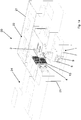
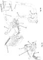
Figure 1a shows a perspective view of an injection molding machine which includes an apparatus in accordance with the invention; -
Figure 1b shows a perspective view of part of the machine ofFigure 1a which includes the apparatus in accordance with the invention; -
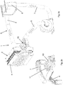
Figure 2a shows a perspective view of a first embodiment of the apparatus in accordance with the invention in a first operating step; -
Figure 2b shows an enlargement of part ofFigure 2a ; -
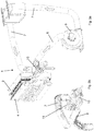
Figure 3a shows a perspective view of the apparatus ofFigure 2a in a second operating step; -
Figure 3b shows an enlargement of part ofFigure 3a ; -
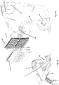
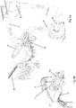
Figure 4a shows a perspective view of the apparatus ofFigure 2a in a third operating step; -
Figure 4b shows an enlargement of part ofFigure 4a ; -
Figure 5a shows a perspective view of the apparatus ofFigure 2a in a fourth operating step; -
Figure 5b shows an enlargement of part ofFigure 5a ; -
Figure 6a shows a perspective view of the apparatus ofFigure 2a in a fifth operating step; -
Figure 6b shows an enlargement of part ofFigure 6a ; -
Figure 7 shows a diagram of the aeraulic circuit of the apparatus in accordance with said first embodiment of the apparatus of the invention; -
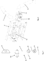
Figure 8 shows a perspective view of some of components of the apparatus in accordance with the invention; -
Figure 9 shows a perspective view of a variant of said first embodiment of the apparatus in accordance with the invention; -
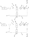
Figures 10a and 10b show an aeraulic circuit diagram of a first variant of a second embodiment of the apparatus of the invention in two different operation modes; -
Figures 11a and 11b show an aeraulic circuit diagram of a second variant of said second embodiment of the apparatus of the invention in two different operation modes; -
Figures 12a and 12b show sectional views of a component of the apparatus in accordance with the invention in two different positions. - The same reference numbers in the Figures identify the same elements or components.
- With reference to
Figure 1a , an injection molding machine is shown comprising the apparatus for cooling and handling preforms in accordance with the invention. Suchinjection molding machine 20 comprises acasing 21 inside of which there are provided at least: - at least one
injection mold 22 comprising a plurality of molding cavities; - an
injection unit 24 for injecting melted plastic in theinjection mold 22 filling said molding cavities; - at least one
extraction plate 4 comprising at least one set of coolinghousings 13, for receiving and retaining at least one set of preforms, extracting them from said molding cavities 23 in a known manner; saidcooling housings 13 being configured to perform a first cooling of the preforms after the extraction from the mold; - and a handling and
cooling apparatus 1. - The cooling
housings 13, of a more or less tubular or anyways hollow shape, are fastened on a suitable support frame or skeleton of theextraction plate 4, aligned in accordance with two directions of the space, and ordered in rows and columns so as to form a matrix. Inside each coolinghousing 13, there is provided a seat with a geometry that reproduces the shape of the outer surface of the preform. Inside each seat, through an insertion opening, a preform to be cooled can be introduced. - The interior space of the frame and of the cooling
housings 13 is crossed by a cooling fluid, for example water and/or air, so as to cool the preforms inserted into said housings. A plurality of channels inside both the extraction plate and the housings allows the cooling fluid to run through a suitable route so as to touch and cool the various tubular bodies of the cooling housings. - With reference to
Figures 1b to 12b , it is shown an apparatus in accordance with the invention, for cooling and handling preforms destined for the production of containers, in particular bottles, in thermoplastic material such as PET, PEN, PP, PLA or other further and suitable material, as well as mixtures thereof, by means of subsequent blow molding or stretch blow-molding of preheated preforms. -
Such apparatus 1 for cooling and handling preforms comprises: - a rotatable handling station or "rotary shell" 2, provided on at least one
face 14 with a plurality of nozzles or tips or pins 3 for retaining and cooling the preforms, and adapted to cooperate with theextraction plate 4; - an
aeraulic circuit 5 connected to therotatable handling station 2. - As the
cooling housings 13 in theextraction plate 4, also the retaining and cooling pins 3 are fastened on theface 14 of therotatable handling station 2, aligned in accordance with two directions in the space, and ordered in rows and columns so as to form a matrix, corresponding to the matrix of thecooling housings 13 on theextraction plate 4. - Said pins 3 are communicating with an internal volume of the
rotatable handling station 2, in turn communicating with theaeraulic circuit 5. - The
aeraulic circuit 5 comprises: - an
aspiration duct 6 for aspirating air from the internal volume of therotatable handling station 2; - a
delivery duct 7 for sending air to said internal volume; - and aspiration means 9, 19, 29 connected to the
aspiration duct 6 and to thedelivery duct 7. - The internal volume of the
rotatable handling station 2 is defined by a single volume or space, communicating on one side with theaeraulic circuit 5 and on the other side with all the pins 3. From the side of theaeraulic circuit 5 the air can only be introduced in said single volume by means of thedelivery duct 7, which is outside of therotatable handling station 2, with consequent air blowing through all of the pins 3; or the air can be only aspirated by said single volume by means of theaspiration duct 6, which is also outside of therotatable handling station 2, this aspiration determining the air passage from all of the pins 3 to the internal volume. Advantageously, cooling means are provided, for example aheat exchanger 8, arranged along thedelivery duct 7 to cool the air sent to therotatable handling station 2. - A further advantage is given by the fact that switching means of the aeraulic circuit are provided for, to pass from a first circuit configuration, in which there is an air passage from the
delivery duct 7 to the inside of therotatable handling station 2, to a second circuit configuration, in which there is an air passage from the inside of therotatable handling station 2 to theaspiration duct 6, whereby, in the first circuit configuration, air can be blown through all the pins of the plurality of retaining and cooling pins 3, while, in the second circuit configuration, air can be aspirated through all the pins of said plurality of pins 3. - Said switching means of the aeraulic circuit comprise at least one
valve - Advantageously, the actuating means 11 which actuate the at least one
valve Figure 9 ) which actuate the rotation of therotatable handling station 2, allowing to select the blowing or aspirating mode independently of the position and of the movement of therotatable handling station 2. - The
rotatable handling station 2 is configured, in turn, to rotate from a loading position for cooperating with theextraction plate 4 to an unloading position for releasing the preforms from said retaining and cooling pins 3. - In the loading position, the
face 14 is arranged parallel to theextraction plate 4 and the retaining and cooling pins 3 are adapted to cooperate withrespective cooling housings 13. By approaching theextraction plate 4 and theface 14, the pins 3 are inserted in the preforms arranged in thecooling housings 13 to perform, in an air blowing step when the aeraulic circuit is in the first circuit configuration, a second cooling of the preforms, and then to retain and extract the preforms from saidcooling housings 13 in a step of aspirating air when the aeraulic circuit is in the second circuit configuration. - The aspiration means are adapted to aspirate air from the internal environment, or internal space, of the
casing 21 in the first circuit configuration, while they are adapted to aspirate air from the inside of therotatable handling station 2 in the second circuit configuration. - A first embodiment of the apparatus in accordance with the invention, shown in Figures from 1b to 9, provides for only one
valve 10, for example a rotatable valve or a linear movement valve, associated with therotatable handling station 2 and configured so as to pass from a first position, in which thevalve 10 allows the air passage from thedelivery duct 7 to the inside of therotatable handling station 2, to a second position, in which thevalve 10 allows the air passage from the inside of therotatable handling station 2 to theaspiration duct 6, whereby, in the first position, air can be blown through the plurality of retaining and cooling pins 3, while, in the second position, air can be aspirated through said plurality of pins 3. - The
valve 10 is connected to the shell of therotatable handling station 2 and respective ends of thedelivery duct 7 and of theaspiration duct 6 are connected thereto, i.e. to thevalve 10. - A
rotatable valve 10 is shown, for example, inFigures 8 ,12a and 12b . - The body of the
rotatable valve 10 comprises two ducts: oneduct 40 defining a first rectilinear axis, and oneduct 41 comprising twosegments curved segment 44, e.g. an L-pipe.Duct 40 andduct 41 are independent from one another, i.e. they are not communicating. Thesegment 42 defines a respective second rectilinear axis and thesegment 43 defines a respective third rectilinear axis, second axis and third axis being substantially orthogonal to one another and also with respect to the first axis of theduct 40. - Therefore, when the actuating means 11 rotate the body of the
rotatable valve 10, for example by approximately 90°, thevalve 10 passes: - from the configuration of
Figure 12a , corresponding to the aforesaid first position, where theduct 41 puts into communication thedelivery duct 7 with the rotatable handling station 2 (blowing step for cooling the preforms), while theduct 40 puts into communication theaspiration duct 6 with the internal environment of thecasing 21; - to the configuration of
Figure 12b , corresponding to the aforesaid second position, where theduct 40 puts into communication thedelivery duct 7 with the internal environment of thecasing 21; while theduct 41 puts into communication therotatable handling station 2 with the aspiration duct 6 (aspirating step for retaining the preforms). - With reference to Figures from 2a to 8b, a first variant of this first embodiment with only one
valve 10 is shown. - In this first variant, the aspiration means 9 are interposed between the
aspiration duct 6 and thedelivery duct 7 so as to aspirate air from theaspiration duct 6 and to introduce it into thedelivery duct 7.Aspiration duct 6 anddelivery duct 7 are therefore in communication by means of said aspiration means 9. - In particular, in this first variant, the aspiration means 9 may consist of a single fan or blower configured to aspirate air from the internal environment of the
casing 21 when thevalve 10 is in the first position, while is adapted to aspirate air from the inside of therotatable handling station 2 when thevalve 10 is in the second position. - Advantageously, the aspiration means 9 preferably have a flow rate of at least 15 m3/min, more preferably from 15 to 80 m3/min, even more preferably from 60 to 80 m3/min, to avoid the collapse of the vacuum inside the
rotary shell 2, in particular when, during the coupling of theface 14 and theextraction plate 4, some columns of coolinghousings 13 are empty and do not contain preforms therewithin. - With reference to
Figure 9 , a second variant of this first embodiment with only onevalve 10 is shown. - In this second variant, the
aspiration duct 6 and thedelivery duct 7 are not communicating, and first aspiration means 19 are provided at an end of theaspiration duct 6 and second aspiration means 29 are provided at an end of thedelivery duct 7, said ends being distal from therotatable handling station 2. - In particular, the first aspiration means 19 can consist of a first fan or blower configured to aspirate air from the internal environment of the
casing 21 when thevalve 10 is in the first position, while is adapted to aspirate air from the inside of therotatable handling station 2 when thevalve 10 is in the second position. The second aspiration means 29 can consist of a second fan or blower, configured to aspirate air from the internal environment of thecasing 21 to send it in thedelivery duct 7, and subsequently to therotatable handling station 2 when thevalve 10 is in the first position, or again in the internal environment of thecasing 21 after cooling, by means of the cooling means 8, the aspirated air. - The first fan, as the fan of the first variant, has a flow rate of at least 15 m3/min, preferably from 15 to 80 m3/min, even more preferably from 60 to 80 m3/min; while the
second fan 29 has a flow rate of preferably about 15-200 m3/min, more preferably from 60 to 200 m3/min. - The process for handling and cooling plastic preforms in the injection molding machine described above, considering the first embodiment of the invention, including its two variants, comprises the following steps:
- providing the
rotatable handling station 2 in the loading position (Figure 1b ) and thevalve 10 in the first position, i.e. the blowing position; - inserting the retaining and cooling pins 3 in the
respective cooling housings 13, and cooling the preforms contained in the latter by means of blowing air through said pins 3 (Figures 2a and 2b ); - actuating the
valve 10, by means of the actuating means 11, to pass from the first position to the second position, i.e. to the aspirating position, and aspirating air through the pins 3 to retain the preforms on the rotatable handling station 2 (Figures 3a and 3b ); - disengaging, i.e. removing, the retaining and cooling pins 3 from the
respective cooling housings 13 continuing to aspirate air through the pins 3 (Figures 4a and 4b ); - rotating the
rotatable handling station 2, by means of the actuating means 12, to pass from the loading position to an unloading position continuing to aspirate air through the pins 3 (Figures 5a and 5b ); - actuating the
valve 10, by means of the first actuating means 11, to pass from said second position to said first position and blowing air through the pins 3 to release the preforms from the pins (Figures 6a and 6b ). - A second embodiment of the apparatus in accordance with the invention, shown in
Figures 10a and 10b , provides instead for at least two valves: avalve 30 is arranged in thedelivery duct 7 downstream the cooling means 8, and avalve 31 is arranged in theaspiration duct 6 upstream the aspiration means 9. - In this second embodiment, the actuating means 11 (not shown in
Figures 10a and 10b ) are adapted to open alternatively thevalve 30 and thevalve 31, whereby, when thevalve 30 is open, thevalve 31 is closed (Figure 10b ) and the air passage is permitted from thedelivery duct 7 to the inside of the rotatable handling station 2 (blowing step for cooling the preforms), while when thevalve 31 is open, thevalve 30 is closed (Figure 10a ) and the air passage is permitted from the inside of therotatable handling station 2 to the aspiration duct 6 (aspirating step for retaining the preforms on the station 2). - With reference to
Figures 10a and 10b , a first variant of this second embodiment with twovalves - In this first variant, the aspiration means 9 are interposed between the
aspiration duct 6 and thedelivery duct 7 so as to aspirate air from theaspiration duct 6 and to introduce it into thedelivery duct 7.Aspiration duct 6 anddelivery duct 7 are therefore in communication by means of said aspiration means 9. - In particular, the aspiration means 9 may consist of only one fan or blower configured to aspirate air from the internal environment of the
casing 21 when thevalve 31 is in the position ofFigure 10b , while is adapted to aspirate air from the inside of therotatable handling station 2 when thevalve 31 is in the position ofFigures 10a . - Advantageously, the aspiration means 9 preferably have a flow rate of at least 15 m3/min, more preferably from 15 to 80 m3/min, even more preferably from 60 to 80 m3/min, to avoid the collapse of the vacuum inside the
rotary shell 2, in particular when, during the coupling of theface 14 and theextraction plate 4, some columns of coolinghousings 13 are empty and do not contain preforms therewithin. - Also for this second embodiment with two valves a second variant can be provided, shown in
Figures 11a and 11b , wherein theaspiration duct 6 and thedelivery duct 7 are not communicating, and first aspiration means 19 are provided at an end of theaspiration duct 6 and second aspiration means 29 are provided at an end of thedelivery duct 7, said ends being distal from therotatable handling station 2. - In particular, the first aspiration means 19 may consist of a first fan or blower configured to aspirate air from the internal environment of the
casing 21 when thevalve 31 assumes the position ofFigure 11b , while is adapted to aspirate air from the inside of therotatable handling station 2 when thevalve 31 assumes the position ofFigure 11a . The second aspiration means 29 may consist of a second fan or blower, configured to aspirate air from the internal environment of thecasing 21 to send it in thedelivery duct 7, and, subsequently, to therotatable handling station 2 when thevalve 30 assumes the position ofFigure 11b , or in the internal environment of thecasing 21 itself, after cooling the air aspirated by means of the cooling means 8, when thevalve 30 assumes the position ofFigure 11a . - Also in this second variant of the second embodiment, the first fan, as the fan of the first variation, preferably has a flow rate of at least 15 m3/min, more preferably from 15 to 80 m3/min, even more preferably from 60 to 80 m3/min; while the second fan preferably has a flow rate of approximately 15-200 m3/min, more preferably from 60 to 200 m3/min.
- The process for handling and cooling plastic preforms in the injection molding machine described above, considering the second embodiment of the invention, including its two variants, comprises the following steps:
- providing the
rotatable handling station 2 in the loading position, thevalve 30 open and thevalve 31 closed, i.e. the blowing position (Figure 10b ); - inserting the retaining and cooling pins 3 in the
respective cooling housings 13 and cooling the preforms contained in the latter by means of blowing air through said pins 3; - closing the
valve 30 and opening thevalve 31, by means of the respective actuating means, to pass from the first circuit configuration to the second circuit configuration, i.e. the aspirating one, and aspirating air through the pins 3 to retain the preforms on the rotatable handling station 2 (Figure 10a ); - disengaging, i.e. removing, the retaining and cooling pins 3 from the
respective cooling housings 13 continuing to aspirate air through the pins 3; - rotating the
rotatable handling station 2, by means of the actuating means 12, to pass from the loading position to an unloading position continuing to aspirate air through the pins 3; - reopening the
valve 30 and reclosing thevalve 31, by means of the respective actuating means, to pass from said second circuit configuration to said first circuit configuration (Figure 10b ), i.e. the blowing one, and blowing air through the pins 3 to release the preforms from the pins.
in which, in said loading position, the retaining and cooling pins of the rotatable handling station are adapted to cooperate with respective cooling housings of the extraction plate to remove, in a step of blowing of air by means of said pins when the aeraulic circuit is in said first aeraulic circuit configuration, a second amount of thermal energy from said preforms, and then to retain and extract any preforms from said cooling housings in a step of aspirating air through said pins when the aeraulic circuit is in said second aeraulic circuit configuration.
Claims (15)
- An apparatus (1) for handling and cooling plastic preforms comprising a rotatable handling station (2), provided with a plurality of retaining and cooling pins (3) for preforms, and adapted to cooperate with an extraction plate (4) adapted to extract the preforms from an injection mold;
an aeraulic circuit (5) connected to said rotatable handling station (2);
wherein said aeraulic circuit (5) comprises- an aspiration duct (6) for aspirating air from inside the rotatable handling station (2);- a delivery duct (7) for sending air to said rotatable handling station (2);- cooling means (8) arranged along said delivery duct (7) for cooling the air sent to said rotatable handling station (2);- aspiration means (9, 19, 29) connected to said aspiration duct (6) and to said delivery duct (7); the apparatus being characterized in that there are further provided switching means of the aeraulic circuit to pass from a first circuit configuration, in which an air passage is possible from the delivery duct (7) to the rotatable handling station (2), to a second circuit configuration, in which an air passage is possible from the rotatable handling station (2) to the aspiration duct (6), so that air can be blown by means of the plurality of retaining and cooling pins (3) in the first circuit configuration, while air can be aspirated by means of said plurality of retaining and cooling pins (3) in the second circuit configuration. - An apparatus according to claim 1, wherein said switching means of the aeraulic circuit comprise- at least one valve (10, 30, 31),- and first actuating means (11) adapted to actuate said at least one valve (10).
- An apparatus according to claim 2, wherein there is provided only one valve (10) associated with said rotatable handling station (2) and configured to pass from a first position, in which the valve (10) allows the air passage from the delivery duct (7) to inside the rotatable handling station (2), to a second position, in which the valve (10) allows the air passage from inside the rotatable handling station (2) to the aspiration duct (6).
- An apparatus according to claim 2, wherein there are provided at least two valves; a first valve (30) of said at least two valves being arranged in the delivery duct (7) downstream of the cooling means (8), and a second valve (31) of said at least two valves being arranged in the aspiration duct (6) upstream of the aspiration means (9),
and wherein said first actuating means are adapted to alternatively open the first valve and the second valve whereby, when the first valve (30) is open, the second valve (31) is closed and the air passage is permitted from the delivery duct (7) to inside the rotatable handling station (2), while when the second valve (31) is open, the first valve (30) is closed and the air passage is permitted from inside the rotatable handling station (2) to the aspiration duct (6). - An apparatus according to any one of the preceding claims, wherein there are provided second actuating means (12), which are independent from said first actuating means (11) and adapted to actuate a rotation of the rotatable handling station (2).
- An apparatus according to any one of the preceding claims, wherein said aspiration means (9) are interposed between the aspiration duct (6) and the delivery duct (7) so as to aspirate air from the aspiration duct (6) and introduce it into the delivery duct (7).
- An apparatus according to claim 3, wherein said aspiration means (9) have a flow rate of at least 15 m3/min.
- An apparatus according to any one of the claims from 1 to 5, wherein the aspiration duct (6) and the delivery duct (7) are not communicating, and first aspiration means (19) are provided at an end of the aspiration duct (6) and second aspiration means (29) are provided at an end of the delivery duct (7).
- An apparatus according to claim 8, wherein the first aspiration means (19) have a flow rate of at least 15 m3/min and the second aspiration means (29) have a flow rate of 15-200 m3/min.
- An apparatus according to any one of the claims from 2 to 9, wherein said at least one valve (10, 30, 31) is either a rotatable valve or a linear movement valve.
- An injection molding machine comprising a casing (21) inside of which there are provided at least- at least one injection mold (22) comprising a plurality of molding cavities;- at least one extraction plate (4) comprising at least one set of cooling housings (13), adapted to receive and retain at least one set of preforms extracted from said molding cavities; said cooling housings (13) being adapted to remove by conduction a first amount of thermal energy from said preforms;- and a handling and cooling apparatus (1) according to claim 1;wherein the rotatable handling station (2) is configured to rotate from a loading position for cooperating with the extraction plate (4) to an unloading position for releasing the preforms from said retaining and cooling pins (3),
wherein, in said loading position, the retaining and cooling pins (3) of the rotatable handling station (2) are adapted to cooperate with respective cooling housings (13) of the extraction plate (4) to remove, in a step of blowing of air by means of said pins (3) when the aeraulic circuit is in said first circuit configuration, a second amount of thermal energy from said preforms, and then to retain and extract the preforms from said cooling housings (13) in a step of aspirating of air through said retaining and cooling pins (3) when the aeraulic circuit is in said second circuit configuration. - An injection molding machine according to claim 11, wherein said aspiration means (9) are adapted to aspirate air from the internal environment of the casing in said first circuit configuration, whereas they are adapted to aspirate air from the inside of the rotatable handling station (2) in said second circuit configuration.
- An injection molding machine according to claim 12, wherein said aspiration means (9) are interposed between the aspiration duct (6) and the delivery duct (7) so as to aspirate air from the aspiration duct (6) and to introduce it into the delivery duct (7).
- An injection molding machine according to claim 11, wherein the aspiration duct (6) and the delivery duct (7) are not communicating, and first aspiration means (19) are provided at an end of the aspiration duct (6) and second aspiration means (29) are provided at an end of the delivery duct (7),
wherein said first aspiration means (19) are adapted to aspirate air from the internal environment of the casing in said first circuit configuration, whereas they are adapted to aspirate air from the inside of the rotatable handling station (2) in said second circuit configuration,
and wherein the second aspiration means (29) are adapted to aspirate air from the internal environment of the casing to send it into the delivery duct (7). - A handling and cooling process of plastic preforms in an injection molding machine according to claim 11, the process comprising the following steps:- providing the rotatable handling station (2) in the loading position, arranged facing the extraction plate (4) containing at least one set of preforms in the respective cooling housings (13), and providing the aeraulic circuit (5) in said first circuit configuration;- inserting the retaining and cooling pins (3) of the rotatable handling station (2) in the respective cooling housings (13) and further cooling the preforms contained in the latter by blowing air through said retaining and cooling pins (3);- switching the aeraulic circuit (5), by means of said switching means, from said first circuit configuration to said second circuit configuration and aspirating air through the retaining and cooling pins (3) to retain the preforms on the rotatable handling station (2);- removing the retaining and cooling pins (3) from the respective cooling housings (13) continuing to aspirate air through the retaining and cooling pins (3);- rotating the rotatable handling station (2) to pass from said loading position to an unloading position continuing to aspirate the air through the retaining and cooling pins (3);- switching the aeraulic circuit (5), by means of said switching means, from said second circuit configuration to said first circuit configuration and blowing air through the retaining and cooling pins (3) to release the preforms from said retaining and cooling pins (3).
Applications Claiming Priority (2)
| Application Number | Priority Date | Filing Date | Title |
|---|---|---|---|
| IT102016000095904A IT201600095904A1 (en) | 2016-09-23 | 2016-09-23 | COOLING AND HANDLING SYSTEM OF PREFORMATIONS IN PLASTIC MATERIAL |
| PCT/EP2017/074143 WO2018055142A1 (en) | 2016-09-23 | 2017-09-22 | Apparatus for cooling and handling preforms in plastic material |
Publications (2)
| Publication Number | Publication Date |
|---|---|
| EP3515684A1 EP3515684A1 (en) | 2019-07-31 |
| EP3515684B1 true EP3515684B1 (en) | 2021-03-17 |
Family
ID=58159325
Family Applications (1)
| Application Number | Title | Priority Date | Filing Date |
|---|---|---|---|
| EP17784557.5A Active EP3515684B1 (en) | 2016-09-23 | 2017-09-22 | Apparatus for cooling and handling preforms in plastic material |
Country Status (6)
| Country | Link |
|---|---|
| US (1) | US11707874B2 (en) |
| EP (1) | EP3515684B1 (en) |
| JP (1) | JP7030796B2 (en) |
| CN (1) | CN109982824B (en) |
| IT (1) | IT201600095904A1 (en) |
| WO (1) | WO2018055142A1 (en) |
Families Citing this family (5)
| Publication number | Priority date | Publication date | Assignee | Title |
|---|---|---|---|---|
| JP7221066B2 (en) * | 2019-01-31 | 2023-02-13 | 住友重機械工業株式会社 | Cooling device for injection molding machine and molded product take-out system |
| IT201900012876A1 (en) * | 2019-07-25 | 2021-01-25 | Sipa Progettazione Automaz | COOLING AND HOLDING PINS FOR COOLING AND MANIPULATION OF PLASTIC PREFORMS |
| AU2021351686B2 (en) * | 2020-09-30 | 2026-04-02 | Owens-Brockway Glass Container Inc. | Submerged combustion melting exhaust systems |
| CN113427745A (en) * | 2021-06-28 | 2021-09-24 | 安徽亦宣金属科技有限公司 | Portable cosmetic powder bottom box production line |
| CN117507257B (en) * | 2023-11-15 | 2024-06-18 | 东莞市现代精工实业有限公司 | Main runner plate mold of liquid distribution plate of thermal management system |
Family Cites Families (15)
| Publication number | Priority date | Publication date | Assignee | Title |
|---|---|---|---|---|
| FR2561166B1 (en) * | 1984-03-16 | 1986-10-10 | Pont A Mousson | PROCESS FOR THE MANUFACTURE OF PLASTIC BOTTLES FROM HOLLOW BLANKS OBTAINED BY MOLDING AND DEVICES FOR CARRYING OUT SAID METHOD |
| US5232641A (en) * | 1991-01-25 | 1993-08-03 | Williamson James T | Rapid cool process |
| JPH1148324A (en) * | 1997-08-08 | 1999-02-23 | Mitsubishi Heavy Ind Ltd | Preform unloader |
| CA2326449C (en) * | 1998-03-31 | 2007-10-02 | Husky Injection Molding Systems, Inc. | Preform post-mold cooling method and apparatus |
| DE19848837B4 (en) * | 1998-10-22 | 2005-03-10 | Netstal Maschinen Ag Naefels | Cooling device for sleeve-shaped injection molded parts produced by an injection molding machine |
| AU6185299A (en) | 1998-10-22 | 2000-05-15 | Netstal-Maschinen Ag | Injection molding machine and method for producing sleeve-shaped injection molded parts, especially preforms |
| NO985317D0 (en) | 1998-11-13 | 1998-11-13 | Borealis As | Polyolefin-based article with modified surface |
| IT1303900B1 (en) * | 1998-11-13 | 2001-03-01 | Biraghi G & Co Bm Sas | DEVICE AND METHOD OF COOLING AND EXTRACTION OF INJECTION MOLDED BODIES |
| AU2003205489A1 (en) | 2002-11-05 | 2004-06-07 | Netstal-Maschinen Ag | Method and device for the secondary treatment and the cooling of preforms |
| US7252497B2 (en) * | 2005-03-10 | 2007-08-07 | Husky Injection Molding Systems Ltd. | Post-molding molded article conditioning apparatus with a selectively controlled transfer flow structure |
| DE202007008217U1 (en) * | 2006-06-29 | 2007-09-13 | Netstal-Maschinen Ag | Auxiliary device with gripper with a variety of nipples |
| US7595018B2 (en) * | 2006-10-16 | 2009-09-29 | Husky Injection Molding Systems Ltd. | Molded article picker |
| JP5740129B2 (en) * | 2010-10-07 | 2015-06-24 | 株式会社松井製作所 | Mold temperature controller |
| AT514631B1 (en) * | 2012-03-12 | 2016-06-15 | Athena Automation Ltd | Cooling of injection molded parts after molding |
| US8926303B2 (en) * | 2013-03-06 | 2015-01-06 | Athena Automation Ltd. | Valve assembly for an injection molding machine |
-
2016
- 2016-09-23 IT IT102016000095904A patent/IT201600095904A1/en unknown
-
2017
- 2017-09-22 WO PCT/EP2017/074143 patent/WO2018055142A1/en not_active Ceased
- 2017-09-22 JP JP2019515442A patent/JP7030796B2/en active Active
- 2017-09-22 CN CN201780071477.0A patent/CN109982824B/en active Active
- 2017-09-22 EP EP17784557.5A patent/EP3515684B1/en active Active
- 2017-09-22 US US16/335,847 patent/US11707874B2/en active Active
Non-Patent Citations (1)
| Title |
|---|
| None * |
Also Published As
| Publication number | Publication date |
|---|---|
| WO2018055142A1 (en) | 2018-03-29 |
| CA3037816A1 (en) | 2018-03-29 |
| US20200061895A1 (en) | 2020-02-27 |
| CN109982824A (en) | 2019-07-05 |
| US11707874B2 (en) | 2023-07-25 |
| JP7030796B2 (en) | 2022-03-07 |
| EP3515684A1 (en) | 2019-07-31 |
| JP2019529179A (en) | 2019-10-17 |
| IT201600095904A1 (en) | 2018-03-23 |
| CN109982824B (en) | 2021-08-10 |
Similar Documents
| Publication | Publication Date | Title |
|---|---|---|
| US11707874B2 (en) | Apparatus for cooling and handling preforms in plastic material | |
| US6663813B2 (en) | Method for cooling molded articles | |
| CN104254436B (en) | To being cooled down after the molding of injection moldings | |
| JP5325305B2 (en) | System for post-processing and transfer of preforms | |
| CN100446958C (en) | Method and apparatus for post-molding cooling of injection molded articles | |
| US6848900B2 (en) | Apparatus for handling injection molded preforms | |
| JP7166439B2 (en) | Cooling mold, manufacturing apparatus and manufacturing method for resin molded product | |
| CN102427930A (en) | Mold support for over-impact base | |
| US20140065256A1 (en) | Method for cooling a mould by circulating a heat-transfer fluid in contact with the external face thereof | |
| CN103402736A (en) | Method and device for blow moulding containers | |
| CN116783055A (en) | Injection blow mold and method | |
| CA3037816C (en) | Apparatus for cooling and handling preforms in plastic material | |
| CN212888874U (en) | Device for forming plastic preforms into plastic containers | |
| CN103906612B (en) | Rear molding system | |
| TR201809024T4 (en) | Plant for forming containers of thermoplastic material. | |
| CN114423585B (en) | Cooling and holding pins of a device for cooling and handling preforms made of plastic material | |
| JP2023096188A (en) | Blow molding apparatus and blow molding method for resin container | |
| KR101138466B1 (en) | An air source device and a method for use in a molding system | |
| WO2000029193A1 (en) | Device and method for cooling and extracting injection-molded hollow bodies | |
| US20080265467A1 (en) | Molding Structure Sub-Assemblies for a Mold and Method of Use | |
| CN119998104A (en) | Preform manufacturing device, manufacturing method and cooling mold | |
| CN117062705A (en) | Injection molding equipment | |
| JP6853073B2 (en) | Blow molding method | |
| CN103874571B (en) | For keeping the device of workpiece | |
| CN118843535A (en) | Device for cooling and removing preforms for producing plastic containers |
Legal Events
| Date | Code | Title | Description |
|---|---|---|---|
| STAA | Information on the status of an ep patent application or granted ep patent |
Free format text: STATUS: UNKNOWN |
|
| STAA | Information on the status of an ep patent application or granted ep patent |
Free format text: STATUS: THE INTERNATIONAL PUBLICATION HAS BEEN MADE |
|
| PUAI | Public reference made under article 153(3) epc to a published international application that has entered the european phase |
Free format text: ORIGINAL CODE: 0009012 |
|
| STAA | Information on the status of an ep patent application or granted ep patent |
Free format text: STATUS: REQUEST FOR EXAMINATION WAS MADE |
|
| 17P | Request for examination filed |
Effective date: 20190419 |
|
| AK | Designated contracting states |
Kind code of ref document: A1 Designated state(s): AL AT BE BG CH CY CZ DE DK EE ES FI FR GB GR HR HU IE IS IT LI LT LU LV MC MK MT NL NO PL PT RO RS SE SI SK SM TR |
|
| AX | Request for extension of the european patent |
Extension state: BA ME |
|
| DAV | Request for validation of the european patent (deleted) | ||
| DAX | Request for extension of the european patent (deleted) | ||
| GRAP | Despatch of communication of intention to grant a patent |
Free format text: ORIGINAL CODE: EPIDOSNIGR1 |
|
| STAA | Information on the status of an ep patent application or granted ep patent |
Free format text: STATUS: GRANT OF PATENT IS INTENDED |
|
| INTG | Intention to grant announced |
Effective date: 20201007 |
|
| GRAS | Grant fee paid |
Free format text: ORIGINAL CODE: EPIDOSNIGR3 |
|
| GRAA | (expected) grant |
Free format text: ORIGINAL CODE: 0009210 |
|
| STAA | Information on the status of an ep patent application or granted ep patent |
Free format text: STATUS: THE PATENT HAS BEEN GRANTED |
|
| AK | Designated contracting states |
Kind code of ref document: B1 Designated state(s): AL AT BE BG CH CY CZ DE DK EE ES FI FR GB GR HR HU IE IS IT LI LT LU LV MC MK MT NL NO PL PT RO RS SE SI SK SM TR |
|
| REG | Reference to a national code |
Ref country code: GB Ref legal event code: FG4D |
|
| REG | Reference to a national code |
Ref country code: CH Ref legal event code: EP |
|
| REG | Reference to a national code |
Ref country code: DE Ref legal event code: R096 Ref document number: 602017034843 Country of ref document: DE |
|
| REG | Reference to a national code |
Ref country code: IE Ref legal event code: FG4D |
|
| REG | Reference to a national code |
Ref country code: AT Ref legal event code: REF Ref document number: 1371836 Country of ref document: AT Kind code of ref document: T Effective date: 20210415 |
|
| REG | Reference to a national code |
Ref country code: LT Ref legal event code: MG9D |
|
| PG25 | Lapsed in a contracting state [announced via postgrant information from national office to epo] |
Ref country code: HR Free format text: LAPSE BECAUSE OF FAILURE TO SUBMIT A TRANSLATION OF THE DESCRIPTION OR TO PAY THE FEE WITHIN THE PRESCRIBED TIME-LIMIT Effective date: 20210317 Ref country code: FI Free format text: LAPSE BECAUSE OF FAILURE TO SUBMIT A TRANSLATION OF THE DESCRIPTION OR TO PAY THE FEE WITHIN THE PRESCRIBED TIME-LIMIT Effective date: 20210317 Ref country code: GR Free format text: LAPSE BECAUSE OF FAILURE TO SUBMIT A TRANSLATION OF THE DESCRIPTION OR TO PAY THE FEE WITHIN THE PRESCRIBED TIME-LIMIT Effective date: 20210618 Ref country code: NO Free format text: LAPSE BECAUSE OF FAILURE TO SUBMIT A TRANSLATION OF THE DESCRIPTION OR TO PAY THE FEE WITHIN THE PRESCRIBED TIME-LIMIT Effective date: 20210617 Ref country code: BG Free format text: LAPSE BECAUSE OF FAILURE TO SUBMIT A TRANSLATION OF THE DESCRIPTION OR TO PAY THE FEE WITHIN THE PRESCRIBED TIME-LIMIT Effective date: 20210617 |
|
| REG | Reference to a national code |
Ref country code: NL Ref legal event code: MP Effective date: 20210317 |
|
| PG25 | Lapsed in a contracting state [announced via postgrant information from national office to epo] |
Ref country code: RS Free format text: LAPSE BECAUSE OF FAILURE TO SUBMIT A TRANSLATION OF THE DESCRIPTION OR TO PAY THE FEE WITHIN THE PRESCRIBED TIME-LIMIT Effective date: 20210317 Ref country code: LV Free format text: LAPSE BECAUSE OF FAILURE TO SUBMIT A TRANSLATION OF THE DESCRIPTION OR TO PAY THE FEE WITHIN THE PRESCRIBED TIME-LIMIT Effective date: 20210317 Ref country code: SE Free format text: LAPSE BECAUSE OF FAILURE TO SUBMIT A TRANSLATION OF THE DESCRIPTION OR TO PAY THE FEE WITHIN THE PRESCRIBED TIME-LIMIT Effective date: 20210317 |
|
| PG25 | Lapsed in a contracting state [announced via postgrant information from national office to epo] |
Ref country code: NL Free format text: LAPSE BECAUSE OF FAILURE TO SUBMIT A TRANSLATION OF THE DESCRIPTION OR TO PAY THE FEE WITHIN THE PRESCRIBED TIME-LIMIT Effective date: 20210317 |
|
| PG25 | Lapsed in a contracting state [announced via postgrant information from national office to epo] |
Ref country code: SM Free format text: LAPSE BECAUSE OF FAILURE TO SUBMIT A TRANSLATION OF THE DESCRIPTION OR TO PAY THE FEE WITHIN THE PRESCRIBED TIME-LIMIT Effective date: 20210317 Ref country code: EE Free format text: LAPSE BECAUSE OF FAILURE TO SUBMIT A TRANSLATION OF THE DESCRIPTION OR TO PAY THE FEE WITHIN THE PRESCRIBED TIME-LIMIT Effective date: 20210317 Ref country code: CZ Free format text: LAPSE BECAUSE OF FAILURE TO SUBMIT A TRANSLATION OF THE DESCRIPTION OR TO PAY THE FEE WITHIN THE PRESCRIBED TIME-LIMIT Effective date: 20210317 Ref country code: LT Free format text: LAPSE BECAUSE OF FAILURE TO SUBMIT A TRANSLATION OF THE DESCRIPTION OR TO PAY THE FEE WITHIN THE PRESCRIBED TIME-LIMIT Effective date: 20210317 |
|
| PG25 | Lapsed in a contracting state [announced via postgrant information from national office to epo] |
Ref country code: IS Free format text: LAPSE BECAUSE OF FAILURE TO SUBMIT A TRANSLATION OF THE DESCRIPTION OR TO PAY THE FEE WITHIN THE PRESCRIBED TIME-LIMIT Effective date: 20210717 Ref country code: PT Free format text: LAPSE BECAUSE OF FAILURE TO SUBMIT A TRANSLATION OF THE DESCRIPTION OR TO PAY THE FEE WITHIN THE PRESCRIBED TIME-LIMIT Effective date: 20210719 Ref country code: PL Free format text: LAPSE BECAUSE OF FAILURE TO SUBMIT A TRANSLATION OF THE DESCRIPTION OR TO PAY THE FEE WITHIN THE PRESCRIBED TIME-LIMIT Effective date: 20210317 Ref country code: SK Free format text: LAPSE BECAUSE OF FAILURE TO SUBMIT A TRANSLATION OF THE DESCRIPTION OR TO PAY THE FEE WITHIN THE PRESCRIBED TIME-LIMIT Effective date: 20210317 Ref country code: RO Free format text: LAPSE BECAUSE OF FAILURE TO SUBMIT A TRANSLATION OF THE DESCRIPTION OR TO PAY THE FEE WITHIN THE PRESCRIBED TIME-LIMIT Effective date: 20210317 |
|
| REG | Reference to a national code |
Ref country code: DE Ref legal event code: R097 Ref document number: 602017034843 Country of ref document: DE |
|
| PLBE | No opposition filed within time limit |
Free format text: ORIGINAL CODE: 0009261 |
|
| STAA | Information on the status of an ep patent application or granted ep patent |
Free format text: STATUS: NO OPPOSITION FILED WITHIN TIME LIMIT |
|
| PG25 | Lapsed in a contracting state [announced via postgrant information from national office to epo] |
Ref country code: AL Free format text: LAPSE BECAUSE OF FAILURE TO SUBMIT A TRANSLATION OF THE DESCRIPTION OR TO PAY THE FEE WITHIN THE PRESCRIBED TIME-LIMIT Effective date: 20210317 Ref country code: DK Free format text: LAPSE BECAUSE OF FAILURE TO SUBMIT A TRANSLATION OF THE DESCRIPTION OR TO PAY THE FEE WITHIN THE PRESCRIBED TIME-LIMIT Effective date: 20210317 Ref country code: ES Free format text: LAPSE BECAUSE OF FAILURE TO SUBMIT A TRANSLATION OF THE DESCRIPTION OR TO PAY THE FEE WITHIN THE PRESCRIBED TIME-LIMIT Effective date: 20210317 |
|
| 26N | No opposition filed |
Effective date: 20211220 |
|
| PG25 | Lapsed in a contracting state [announced via postgrant information from national office to epo] |
Ref country code: SI Free format text: LAPSE BECAUSE OF FAILURE TO SUBMIT A TRANSLATION OF THE DESCRIPTION OR TO PAY THE FEE WITHIN THE PRESCRIBED TIME-LIMIT Effective date: 20210317 |
|
| REG | Reference to a national code |
Ref country code: BE Ref legal event code: MM Effective date: 20210930 |
|
| GBPC | Gb: european patent ceased through non-payment of renewal fee |
Effective date: 20210922 |
|
| PG25 | Lapsed in a contracting state [announced via postgrant information from national office to epo] |
Ref country code: IS Free format text: LAPSE BECAUSE OF FAILURE TO SUBMIT A TRANSLATION OF THE DESCRIPTION OR TO PAY THE FEE WITHIN THE PRESCRIBED TIME-LIMIT Effective date: 20210717 Ref country code: MC Free format text: LAPSE BECAUSE OF FAILURE TO SUBMIT A TRANSLATION OF THE DESCRIPTION OR TO PAY THE FEE WITHIN THE PRESCRIBED TIME-LIMIT Effective date: 20210317 |
|
| PG25 | Lapsed in a contracting state [announced via postgrant information from national office to epo] |
Ref country code: IE Free format text: LAPSE BECAUSE OF NON-PAYMENT OF DUE FEES Effective date: 20210922 Ref country code: GB Free format text: LAPSE BECAUSE OF NON-PAYMENT OF DUE FEES Effective date: 20210922 Ref country code: BE Free format text: LAPSE BECAUSE OF NON-PAYMENT OF DUE FEES Effective date: 20210930 |
|
| PG25 | Lapsed in a contracting state [announced via postgrant information from national office to epo] |
Ref country code: CY Free format text: LAPSE BECAUSE OF FAILURE TO SUBMIT A TRANSLATION OF THE DESCRIPTION OR TO PAY THE FEE WITHIN THE PRESCRIBED TIME-LIMIT Effective date: 20210317 |
|
| P01 | Opt-out of the competence of the unified patent court (upc) registered |
Effective date: 20230525 |
|
| PG25 | Lapsed in a contracting state [announced via postgrant information from national office to epo] |
Ref country code: HU Free format text: LAPSE BECAUSE OF FAILURE TO SUBMIT A TRANSLATION OF THE DESCRIPTION OR TO PAY THE FEE WITHIN THE PRESCRIBED TIME-LIMIT; INVALID AB INITIO Effective date: 20170922 |
|
| PG25 | Lapsed in a contracting state [announced via postgrant information from national office to epo] |
Ref country code: MK Free format text: LAPSE BECAUSE OF FAILURE TO SUBMIT A TRANSLATION OF THE DESCRIPTION OR TO PAY THE FEE WITHIN THE PRESCRIBED TIME-LIMIT Effective date: 20210317 |
|
| PG25 | Lapsed in a contracting state [announced via postgrant information from national office to epo] |
Ref country code: MT Free format text: LAPSE BECAUSE OF FAILURE TO SUBMIT A TRANSLATION OF THE DESCRIPTION OR TO PAY THE FEE WITHIN THE PRESCRIBED TIME-LIMIT Effective date: 20210317 |
|
| REG | Reference to a national code |
Ref country code: CH Ref legal event code: U11 Free format text: ST27 STATUS EVENT CODE: U-0-0-U10-U11 (AS PROVIDED BY THE NATIONAL OFFICE) Effective date: 20251001 |
|
| PGFP | Annual fee paid to national office [announced via postgrant information from national office to epo] |
Ref country code: DE Payment date: 20250919 Year of fee payment: 9 |
|
| PGFP | Annual fee paid to national office [announced via postgrant information from national office to epo] |
Ref country code: TR Payment date: 20250916 Year of fee payment: 9 Ref country code: IT Payment date: 20250926 Year of fee payment: 9 Ref country code: LU Payment date: 20250919 Year of fee payment: 9 |
|
| PGFP | Annual fee paid to national office [announced via postgrant information from national office to epo] |
Ref country code: FR Payment date: 20250922 Year of fee payment: 9 Ref country code: AT Payment date: 20250919 Year of fee payment: 9 |
|
| PGFP | Annual fee paid to national office [announced via postgrant information from national office to epo] |
Ref country code: CH Payment date: 20251001 Year of fee payment: 9 |