EP3514917B1 - Control circuit, power supply structure, and electronic cigarette - Google Patents
Control circuit, power supply structure, and electronic cigarette Download PDFInfo
- Publication number
- EP3514917B1 EP3514917B1 EP17854992.9A EP17854992A EP3514917B1 EP 3514917 B1 EP3514917 B1 EP 3514917B1 EP 17854992 A EP17854992 A EP 17854992A EP 3514917 B1 EP3514917 B1 EP 3514917B1
- Authority
- EP
- European Patent Office
- Prior art keywords
- contact
- nth
- negative
- positive
- bat1
- Prior art date
- Legal status (The legal status is an assumption and is not a legal conclusion. Google has not performed a legal analysis and makes no representation as to the accuracy of the status listed.)
- Active
Links
Images



Classifications
-
- H—ELECTRICITY
- H02—GENERATION; CONVERSION OR DISTRIBUTION OF ELECTRIC POWER
- H02J—ELECTRIC POWER NETWORKS; CIRCUIT ARRANGEMENTS OR SYSTEMS FOR SUPPLYING OR DISTRIBUTING ELECTRIC POWER; SYSTEMS FOR STORING ELECTRIC ENERGY
- H02J7/00—Circuit arrangements for charging or discharging batteries or for supplying loads from batteries
- H02J7/36—Arrangements using end-cell switching
-
- A—HUMAN NECESSITIES
- A24—TOBACCO; CIGARS; CIGARETTES; SIMULATED SMOKING DEVICES; SMOKERS' REQUISITES
- A24F—SMOKERS' REQUISITES; MATCH BOXES; SIMULATED SMOKING DEVICES
- A24F40/00—Electrically operated smoking devices; Component parts thereof; Manufacture thereof; Maintenance or testing thereof; Charging means specially adapted therefor
- A24F40/40—Constructional details, e.g. connection of cartridges and battery parts
-
- A—HUMAN NECESSITIES
- A24—TOBACCO; CIGARS; CIGARETTES; SIMULATED SMOKING DEVICES; SMOKERS' REQUISITES
- A24F—SMOKERS' REQUISITES; MATCH BOXES; SIMULATED SMOKING DEVICES
- A24F40/00—Electrically operated smoking devices; Component parts thereof; Manufacture thereof; Maintenance or testing thereof; Charging means specially adapted therefor
- A24F40/50—Control or monitoring
-
- H—ELECTRICITY
- H01—ELECTRIC ELEMENTS
- H01M—PROCESSES OR MEANS, e.g. BATTERIES, FOR THE DIRECT CONVERSION OF CHEMICAL ENERGY INTO ELECTRICAL ENERGY
- H01M50/00—Constructional details or processes of manufacture of the non-active parts of electrochemical cells other than fuel cells, e.g. hybrid cells
- H01M50/20—Mountings; Secondary casings or frames; Racks, modules or packs; Suspension devices; Shock absorbers; Transport or carrying devices; Holders
- H01M50/204—Racks, modules or packs for multiple batteries or multiple cells
-
- H—ELECTRICITY
- H01—ELECTRIC ELEMENTS
- H01M—PROCESSES OR MEANS, e.g. BATTERIES, FOR THE DIRECT CONVERSION OF CHEMICAL ENERGY INTO ELECTRICAL ENERGY
- H01M50/00—Constructional details or processes of manufacture of the non-active parts of electrochemical cells other than fuel cells, e.g. hybrid cells
- H01M50/20—Mountings; Secondary casings or frames; Racks, modules or packs; Suspension devices; Shock absorbers; Transport or carrying devices; Holders
- H01M50/256—Carrying devices, e.g. belts
-
- H—ELECTRICITY
- H01—ELECTRIC ELEMENTS
- H01M—PROCESSES OR MEANS, e.g. BATTERIES, FOR THE DIRECT CONVERSION OF CHEMICAL ENERGY INTO ELECTRICAL ENERGY
- H01M50/00—Constructional details or processes of manufacture of the non-active parts of electrochemical cells other than fuel cells, e.g. hybrid cells
- H01M50/20—Mountings; Secondary casings or frames; Racks, modules or packs; Suspension devices; Shock absorbers; Transport or carrying devices; Holders
- H01M50/271—Lids or covers for the racks or secondary casings
-
- H—ELECTRICITY
- H01—ELECTRIC ELEMENTS
- H01M—PROCESSES OR MEANS, e.g. BATTERIES, FOR THE DIRECT CONVERSION OF CHEMICAL ENERGY INTO ELECTRICAL ENERGY
- H01M50/00—Constructional details or processes of manufacture of the non-active parts of electrochemical cells other than fuel cells, e.g. hybrid cells
- H01M50/20—Mountings; Secondary casings or frames; Racks, modules or packs; Suspension devices; Shock absorbers; Transport or carrying devices; Holders
- H01M50/296—Mountings; Secondary casings or frames; Racks, modules or packs; Suspension devices; Shock absorbers; Transport or carrying devices; Holders characterised by terminals of battery packs
-
- H—ELECTRICITY
- H02—GENERATION; CONVERSION OR DISTRIBUTION OF ELECTRIC POWER
- H02J—ELECTRIC POWER NETWORKS; CIRCUIT ARRANGEMENTS OR SYSTEMS FOR SUPPLYING OR DISTRIBUTING ELECTRIC POWER; SYSTEMS FOR STORING ELECTRIC ENERGY
- H02J7/00—Circuit arrangements for charging or discharging batteries or for supplying loads from batteries
- H02J7/50—Circuit arrangements for charging or discharging batteries or for supplying loads from batteries acting upon multiple batteries simultaneously or sequentially
- H02J7/575—Parallel/serial switching of connection of batteries to charge or load circuit
-
- Y—GENERAL TAGGING OF NEW TECHNOLOGICAL DEVELOPMENTS; GENERAL TAGGING OF CROSS-SECTIONAL TECHNOLOGIES SPANNING OVER SEVERAL SECTIONS OF THE IPC; TECHNICAL SUBJECTS COVERED BY FORMER USPC CROSS-REFERENCE ART COLLECTIONS [XRACs] AND DIGESTS
- Y02—TECHNOLOGIES OR APPLICATIONS FOR MITIGATION OR ADAPTATION AGAINST CLIMATE CHANGE
- Y02E—REDUCTION OF GREENHOUSE GAS [GHG] EMISSIONS, RELATED TO ENERGY GENERATION, TRANSMISSION OR DISTRIBUTION
- Y02E60/00—Enabling technologies; Technologies with a potential or indirect contribution to GHG emissions mitigation
- Y02E60/10—Energy storage using batteries
Definitions
- the present disclosure relates to the technical field of electronic cigarettes, and in particular, to a control circuit, a power supply structure, and an electronic cigarette using the power supply structure.
- the power connection method in traditional electronic cigarettes generally uses batteries in series or in parallel, and an electronic cigarette uses only one connection method.
- the electronic cigarette needs to be added with power inductors and full bridge circuits to set up a small power supply to adjust the output voltages.
- the battery voltage is 3.7V, and the output voltage can be in the range of 0-9V after adjustment.
- the addition of power inductors and full bridge circuits not only generates electromagnetic interference around it, but also increases the cost of the electronic cigarette.
- WO 2015/179318 A1 disclose various circuit arrangements for changing the output voltage and/or current of a set of batteries, depending on how their poles are connected.
- the present disclosure provides a power supply structure including a battery receiving casing for receiving at least two battery cells, the power supply structure further includes a bottom plate provided with contacts, the bottom plate is disposed in the battery receiving casing; according to claim 1.
- Preferred embodiments are disclosed in the dependent claims.
- FIG. 1 is a block diagram of an electronic cigarette according to an embodiment.
- the electronic cigarette includes a mode state indicating circuit 100, a microcontroller 200, an atomizing circuit 300, and a power supply structure 400.
- the positive output terminal of the power supply structure 400 is connected to the power input terminals of the microcontroller 200 and the atomizing circuit 300.
- the microcontroller 200 is electrically connected to the mode state indicating circuit 100 and the atomizing circuit 300, respectively.
- the power supply structure 400 supplies power to the microcontroller 200 and the atomizing circuit 300.
- the microcontroller 200 controls the operation of the atomizing circuit 300, and controls the mode state indicating circuit 100 to indicate a corresponding operating state of the power supply structure 400.
- FIG. 2 is a block diagram of the power supply structure of FIG. 1 .
- the power supply structure 400 includes a first battery cell 410, a second battery cell 420, and a bottom plate 430.
- the positive pole (+) and the negative pole (-) of the first battery cell 410, and the positive pole (+) and the negative pole (-) of the second battery cell 420 are all led out and connected to the bottom plate 430 provided with contacts, and by connecting to different contacts, a series connection relationship or a parallel connection relationship is formed. That is, the first battery cell 410 and the second battery cell 420 are connected in series, or the first battery cell 410 and the second battery cell 420 are connected in parallel. It can be understood that the number of battery cells can be multiple, to thereby switch between series connection and parallel connection of two or more battery cells.
- the bottom plate 430 has a first surface 431 and a second surface 432, and the first surface 431 and the second surface 432 are each provided with contacts.
- the first battery cell 410 and the second battery cell 420 form a series connection relationship.
- the leading ends of the positive pole and the negative pole of the first battery cell 410 and the second battery cell 420 are connected to the contacts provided on the second surface 432 of the bottom plate 430, the first battery cell 410 and the second battery cell 420 form a parallel connection relationship.
- other methods may be employed, for example, two groups of contacts are disposed at different positions on the same surface of the bottom plate 430 for forming a series connection or parallel connection between the battery cells.
- the series connection and the parallel connection of the battery cells can be switched by turning over the bottom plate 430.
- the series connection and the parallel connection of the battery cells can be switched by rotating or moving the bottom plate 430.
- the bottom plate is installed at one end of the battery cells in the power supply structure 400, and its relative position in the power supply structure 400 is not limited.
- FIG. 3 shows a specific lead-out manner of the first battery cell 410 and the second battery cell 420 and the structure of the bottom plate 430.
- the positive pole (+) of the first battery cell 410 is led out through a lead wire and connected to a first contact member 411.
- the positive pole (+) of the second battery cell 420 is led out through a lead wire and connected to a second contact member 421.
- the positive pole (+) of the first battery cell 410 is further connected to the positive output terminal (VCC) of the power supply structure 400 through another lead wire.
- the power supply structure 400 further includes a third contact member 440 which is led out through a lead wire and connected to the positive output terminal (VCC) of the power supply structure 400, and a fourth contact member 450 which is led out through a lead wire and connected to the negative electrode of the circuit board of the electronic cigarette.
- the contacts on the bottom plate 430 are electrically connected to the negative pole (-) of the first battery cell 410, the first contact member 411, the negative pole (-) of the second battery cell 420, the second contact member 421 and the third contact member 440, respectively.
- the bottom plate 430 has a first surface 431 and a second surface 432.
- a first negative contact (BAT1-) On each of the first surface 431 and the second surface 432, there are provided with a first negative contact (BAT1-), a first positive contact (BAT1+), a second contact (BAR), a second positive contact (BAT2+), a second negative contact (BAT2-), and a ground contact (GND).
- the first negative contact (BAT1-), the first positive contact (BAT1+), the second contact (BAR), the second positive contact (BAT2+), the second negative contact (BAT2-) and the ground contact (GND) on the first surface 431 are electrically connected to the negative pole (-) of the first battery cell 410, the first contact member 411, the third contact member 440, the second contact member 421, the negative pole (-) of the second battery cell 420 and the fourth contact member 450, respectively.
- the first negative contact (BAT1-), the first positive contact (BAT1+), the second contact (BAR), the second positive contact (BAT2+), the second negative contact (BAT2-) and the ground contact (GND) on the second surface 432 are electrically connected to the negative pole (-) of the first battery cell 410, the first contact member 411, the third contact member 440, the second contact member 421, the negative pole (-) of the second battery cell 420 and the fourth contact member 450, respectively.
- the first surface 431 of the bottom plate 430 is provided with a serial connection identification
- the second surface 432 is provided with a parallel connection identification.
- it may be designed as a text identifier or a symbol identifier.
- the second contact (BAR) is a contact for connecting to a reverse protection circuit.
- the first negative contact (BAT1-) and the second positive contact (BAT2+) are electrically connected, the first positive contact (BAT1+) and the second contact (BAR) are electrically connected, the second negative contact (BAT2-) and the ground contact (GND) are electrically connected.
- the bottom plate 430 when the bottom plate 430 is electrically connected to the battery cells with the first surface 431, the negative pole (-) of the first battery cell 410 and the positive pole (+) of the second battery cell 420 are electrically connected, and the negative pole (-) of the second battery cell 420 is grounded, thereby forming a series connection relationship.
- the first positive contact (BAT1+) and the second contact (BAR) in FIG. 4a may also be disconnected.
- the first negative contact (BAT1-), the second negative contact (BAT2-) and the ground contact (GND) are electrically connected, the second contact (BAR) and the second positive contact (BAT2+) are electrically connected.
- the negative pole (-) of the first battery cell 410 is grounded, such that the first battery cell 410 is connected between the positive output terminal (VCC) and the ground.
- the positive pole (+) of the second battery cell 420 is connected to the positive output terminal (VCC) through the second contact member 421 and the third contact member 440, and the negative pole (-) of the second battery cell 420 is grounded, such that the second battery cell 420 is connected between the positive output terminal (VCC) and the ground.
- the first battery cell 410 and the second battery cell 420 form a parallel connection relationship.
- the series and parallel switching of the battery cells can be realized by changing the surface of the bottom plate in contact with the battery cells, to satisfy the user's demand for different power outputs.
- the power supply structure 400 includes a battery receiving casing 490.
- the battery receiving casing 490 has a substantially cylindrical shape.
- the first battery cell 410 and the second battery cell 420 are received in the battery receiving casing 490, the bottom plate 430 is disposed opposite to the battery cells, the bottom plate 430 and the battery cells are electrically connected, and the bottom plate 430 is fixed by a cover 480.
- the contact members are not shown in FIG. 5 .
- the contact members may be a pogo pin or an elastic electrode, and the elastic electrode may be an elastic sheet.
- the relative positional relationship between the contacts of the first group of contacts on the first surface 431 is the same as the relative positional relationship between the contacts of the second group of contacts on the second surface 432.
- the power supply structure 400 may further include a first reverse protection circuit 460 and a second reverse protection circuit 470.
- the first reverse protection circuit 460 is connected between the positive pole (+) of the first battery cell 410 and the positive output terminal (VCC) of the power supply structure 400
- the second reverse protection circuit 470 is connected between the third contact member 440 (see FIG. 3 ) and the positive output terminal (VCC) of the power supply structure 400.
- the power supply structure 400 includes a control circuit, the control circuit is formed on the bottom plate (circuit board), and the control circuit includes two groups of contacts provided on the bottom plate (circuit board).
- the two groups of contacts include a first group of contacts and a second group of contacts. It can be understood that the first group of contacts and the second group of contacts may be respectively provided on the front surface and the back surface of the bottom plate (circuit board), or may be provided on the same surface of the bottom plate.
- the first group of contacts are provided at a first position of the bottom plate, and the second group of contacts are provided at a second position of the bottom plate.
- the first position and the second position are symmetrical with respect to a central axis along the distribution direction of the contacts on the bottom plate.
- the first group of contacts includes:
- the nth negative contact is electrically connected to the ground contact (GND)
- the nth positive contact is electrically connected to the (n-1)th negative contact
- the (n-1)th positive contact is electrically connected to the (n-2)th negative contact, and so on, until the second positive contact (BAT2+) is electrically connected to the first negative contact (BAT1-).
- the first positive contact (BAT1+) and the Nth contact are electrically connected.
- the first group of contacts includes:
- the nth negative contact is electrically connected to the ground contact (GND)
- the nth positive contact is electrically connected to the (n-1)th negative contact
- the (n-1)th positive contact is electrically connected to the (n-2)th negative contact, and so on, until the second positive contact (BAT2+) is electrically connected to the first negative contact (BAT1-).
- the n battery cells can form a series connection relationship.
- the Nth battery cell can be connected to a reverse protection circuit through the Nth contact.
- the second group of contacts includes:
- ground contact is electrically connected to the first negative contact (BAT1-) and the Nth negative contact, and the Nth positive contact is electrically connected to the Nth contact.
- the second group of contacts includes:
- the ground contact is electrically connected to the first negative contact (BAT1-) and the Nth negative contact
- the Nth positive contact is electrically connected to the Nth contact.
- the positive pole (+) of the first battery cell 410 is connected to the first positive contact (BAT1+) through a contact member, and the negative pole (-) of the first battery cell 410 is connected to the first negative contact (BAT1-).
- the negative pole (-) of the Nth battery cell is connected to the Nth negative contact, and the positive pole (+) of the Nth battery cell is connected to the Nth positive contact through a contact member.
- the Nth contact is connected to a contact member, and the ground contact (GND) is connected to a contact member.
- the negative pole (-) of the first battery cell 410 is connected to the first negative contact (BAT1-).
- the negative pole (-) of the Nth battery cell is connected to the Nth negative contact
- the positive pole (+) of the Nth battery cell is connected to the Nth positive contact through a contact member.
- the Nth contact is connected to a contact member
- the ground contact (GND) is connected to a contact member.
- first group of contacts When the first group of contacts are electrically connected to the n battery cells, a series connection relationship is formed between the n battery cells; when the second group of contacts are electrically connected to the n battery cells, a parallel connection relationship is formed between the n battery cells. It can be understood that the switching between the first group of contacts and the second group of contacts can be achieved by turning over the bottom plate, moving or rotating the bottom plate.
- the nth contact (BARn), the nth positive contact (BATn+) and the nth negative contact (BATn-) are added into the first group of contacts or the second group of contacts.
- the (n-1)th negative contact is electrically connected to the nth positive contact
- the nth negative contact (BATn-) is electrically connected to the ground contact (GND).
- the ground contact (GND) is electrically connected to the nth negative contact (BATn-)
- the nth contact (BARn) is electrically connected to the nth positive contact (BATn+).
- the battery receiving casing 490 of the power supply structure 400 is received with three battery cells.
- each group of contacts may include eight or nine contacts. Taking nine contacts as example, the nine contacts include a first negative contact (BAT1-), a first positive contact (BAT1+), a second contact (BAR2), a second positive contact (BAT2+), a second negative contact (BAT2-), a third contact (BAR3), a third positive contact (BAT3+), a third negative contact (BAT3-), and a ground contact (GND).
- the contacts of the first group of contacts are connected as follows:
- the first negative contact (BAT1-) and the second positive contact (BAT2+) are electrically connected.
- the first positive contact (BAT1+), the second contact (BAR2) and the third contact (BAR3) are electrically connected.
- the second negative contact (BAT2-) and the third positive contact (BAT3+) are electrically connected.
- the third negative contact (BAT3-) and the ground contact (GND) are electrically connected.
- the contacts of the second group of contacts are connected as follows:
- the first negative contact (BAT1-), the second negative contact (BAT2-), the third negative contact (BAT3-) and the ground contact (GND) are electrically connected.
- the second contact (BAR2) and the second positive contact (BAT2+) are electrically connected.
- the third contact (BAR3) and the third positive contact (BAT3+) are electrically connected.
- the power supply structure 400 may further include a first reverse protection circuit 460 and an Nth reverse protection circuit 470.
- the first reverse protection circuit 460 is connected between the positive pole (+) of the first battery cell 410 and the positive output terminal (VCC) of the power supply structure 400.
- the Nth reverse protection circuit 470 is connected between the contact member connected to the Nth contact and the positive output terminal (VCC) of the power supply structure 400.
- a control circuit is provided.
- the details of the control circuit are similar to those of the control circuit described above, and are not described herein again.
- an electronic cigarette is provided.
- the electronic cigarette includes the control circuit described above.
- an electronic cigarette in one embodiment, is provided.
- the electronic cigarette includes the power supply structure 400 described above. Also included is a mode state indicating circuit 100, a microcontroller 200 and an atomizing circuit 300.
- the positive output terminal of the power supply structure 400 is connected to the power input terminals of the microcontroller 200 and the atomizing circuit 300.
- the microcontroller 200 is electrically connected to the mode state indicating circuit 100 and the atomizing circuit 300, respectively.
- the power supply structure 400 supplies power to the microcontroller 200 and the atomizing circuit 300.
- the microcontroller 200 controls the operation of the atomizing circuit 300, and controls the mode state indicating circuit 100 to indicate a corresponding operating state of the power supply structure 400.
- the battery cells in the electronic cigarette are connected to different contacts on the bottom plate, to thereby change the series or parallel connection relationship of the battery cells for providing different power outputs. The operation is simple and convenient.
Landscapes
- Chemical & Material Sciences (AREA)
- Chemical Kinetics & Catalysis (AREA)
- Electrochemistry (AREA)
- General Chemical & Material Sciences (AREA)
- Engineering & Computer Science (AREA)
- Power Engineering (AREA)
- Battery Mounting, Suspending (AREA)
- Charge And Discharge Circuits For Batteries Or The Like (AREA)
Description
- The present disclosure relates to the technical field of electronic cigarettes, and in particular, to a control circuit, a power supply structure, and an electronic cigarette using the power supply structure.
- The power connection method in traditional electronic cigarettes generally uses batteries in series or in parallel, and an electronic cigarette uses only one connection method. In this case, in order to realize multi-function output, the electronic cigarette needs to be added with power inductors and full bridge circuits to set up a small power supply to adjust the output voltages. Under normal circumstances, the battery voltage is 3.7V, and the output voltage can be in the range of 0-9V after adjustment. However, the addition of power inductors and full bridge circuits not only generates electromagnetic interference around it, but also increases the cost of the electronic cigarette.
-
WO 2015/179318 A1 ,DE 10 2014 01950 A1 andWO 2016/150979 A1 disclose various circuit arrangements for changing the output voltage and/or current of a set of batteries, depending on how their poles are connected. - In view of the above, the present disclosure provides a power supply structure including a battery receiving casing for receiving at least two battery cells, the power supply structure further includes a bottom plate provided with contacts, the bottom plate is disposed in the battery receiving casing; according to claim 1. Preferred embodiments are disclosed in the dependent claims.
-
-
FIG. 1 is a block diagram of an electronic cigarette according to an embodiment. -
FIG. 2 is a block diagram of the power supply structure ofFIG. 1 . -
FIG. 3 is a schematic diagram showing a specific lead-out manner of the first battery cell and the second battery cell and the structure of the bottom plate in the power supply structure ofFIG. 2 . -
FIG. 4a is a schematic diagram showing the arrangement and connection relationship of the first group of contacts on the first surface of the bottom plate. -
FIG. 4b is a schematic diagram showing the arrangement and connection relationship of the second group of contacts on the second surface of the bottom plate. -
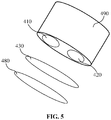
FIG. 5 is a schematic view of the power supply structure ofFIG. 2 . -
FIG. 6 is a schematic view showing the first group of contacts in another embodiment. -
FIG. 7 is a schematic view showing the second group of contacts in another embodiment. - Further description will be made below with reference to the accompanying drawings and embodiments.
-
FIG. 1 is a block diagram of an electronic cigarette according to an embodiment. The electronic cigarette includes a modestate indicating circuit 100, amicrocontroller 200, anatomizing circuit 300, and apower supply structure 400. The positive output terminal of thepower supply structure 400 is connected to the power input terminals of themicrocontroller 200 and the atomizingcircuit 300. Themicrocontroller 200 is electrically connected to the modestate indicating circuit 100 and the atomizingcircuit 300, respectively. - The
power supply structure 400 supplies power to themicrocontroller 200 and the atomizingcircuit 300. Themicrocontroller 200 controls the operation of the atomizingcircuit 300, and controls the modestate indicating circuit 100 to indicate a corresponding operating state of thepower supply structure 400. -
FIG. 2 is a block diagram of the power supply structure ofFIG. 1 . Thepower supply structure 400 includes afirst battery cell 410, asecond battery cell 420, and abottom plate 430. The positive pole (+) and the negative pole (-) of thefirst battery cell 410, and the positive pole (+) and the negative pole (-) of thesecond battery cell 420 are all led out and connected to thebottom plate 430 provided with contacts, and by connecting to different contacts, a series connection relationship or a parallel connection relationship is formed. That is, thefirst battery cell 410 and thesecond battery cell 420 are connected in series, or thefirst battery cell 410 and thesecond battery cell 420 are connected in parallel. It can be understood that the number of battery cells can be multiple, to thereby switch between series connection and parallel connection of two or more battery cells. - In this embodiment, the
bottom plate 430 has afirst surface 431 and asecond surface 432, and thefirst surface 431 and thesecond surface 432 are each provided with contacts. When the leading ends of the positive pole and the negative pole of thefirst battery cell 410 and thesecond battery cell 420 are connected to the contacts provided on thefirst surface 431 of thebottom plate 430, thefirst battery cell 410 and thesecond battery cell 420 form a series connection relationship. When the leading ends of the positive pole and the negative pole of thefirst battery cell 410 and thesecond battery cell 420 are connected to the contacts provided on thesecond surface 432 of thebottom plate 430, thefirst battery cell 410 and thesecond battery cell 420 form a parallel connection relationship. It can be understood that in addition to setting different contacts in the above manner, other methods may be employed, for example, two groups of contacts are disposed at different positions on the same surface of thebottom plate 430 for forming a series connection or parallel connection between the battery cells. - It can be understood that when a group of contacts are provided on each of the
first surface 431 and thesecond surface 432, the series connection and the parallel connection of the battery cells can be switched by turning over thebottom plate 430. When two groups of contacts are disposed at different positions on the same surface, the series connection and the parallel connection of the battery cells can be switched by rotating or moving thebottom plate 430. It should be noted that the bottom plate is installed at one end of the battery cells in thepower supply structure 400, and its relative position in thepower supply structure 400 is not limited. -
FIG. 3 shows a specific lead-out manner of thefirst battery cell 410 and thesecond battery cell 420 and the structure of thebottom plate 430. - As shown in
FIG. 3 , the positive pole (+) of thefirst battery cell 410 is led out through a lead wire and connected to afirst contact member 411. The positive pole (+) of thesecond battery cell 420 is led out through a lead wire and connected to asecond contact member 421. The positive pole (+) of thefirst battery cell 410 is further connected to the positive output terminal (VCC) of thepower supply structure 400 through another lead wire. Thepower supply structure 400 further includes athird contact member 440 which is led out through a lead wire and connected to the positive output terminal (VCC) of thepower supply structure 400, and afourth contact member 450 which is led out through a lead wire and connected to the negative electrode of the circuit board of the electronic cigarette. - The contacts on the
bottom plate 430 are electrically connected to the negative pole (-) of thefirst battery cell 410, thefirst contact member 411, the negative pole (-) of thesecond battery cell 420, thesecond contact member 421 and thethird contact member 440, respectively. - Specifically, referring to
FIG. 3 , thebottom plate 430 has afirst surface 431 and asecond surface 432. On each of thefirst surface 431 and thesecond surface 432, there are provided with a first negative contact (BAT1-), a first positive contact (BAT1+), a second contact (BAR), a second positive contact (BAT2+), a second negative contact (BAT2-), and a ground contact (GND). The first negative contact (BAT1-), the first positive contact (BAT1+), the second contact (BAR), the second positive contact (BAT2+), the second negative contact (BAT2-) and the ground contact (GND) on thefirst surface 431 are electrically connected to the negative pole (-) of thefirst battery cell 410, thefirst contact member 411, thethird contact member 440, thesecond contact member 421, the negative pole (-) of thesecond battery cell 420 and thefourth contact member 450, respectively. Or optionally, the first negative contact (BAT1-), the first positive contact (BAT1+), the second contact (BAR), the second positive contact (BAT2+), the second negative contact (BAT2-) and the ground contact (GND) on thesecond surface 432 are electrically connected to the negative pole (-) of thefirst battery cell 410, thefirst contact member 411, thethird contact member 440, thesecond contact member 421, the negative pole (-) of thesecond battery cell 420 and thefourth contact member 450, respectively. - In order to facilitate the user to know the connection relationship between the
bottom plate 430 and the battery cells, thefirst surface 431 of thebottom plate 430 is provided with a serial connection identification, and thesecond surface 432 is provided with a parallel connection identification. Specifically, it may be designed as a text identifier or a symbol identifier. It is understood that the second contact (BAR) is a contact for connecting to a reverse protection circuit. - As shown in
FIG. 4a , on thefirst surface 431, the first negative contact (BAT1-) and the second positive contact (BAT2+) are electrically connected, the first positive contact (BAT1+) and the second contact (BAR) are electrically connected, the second negative contact (BAT2-) and the ground contact (GND) are electrically connected. - With reference to
FIG. 3 andFIG. 4a , when thebottom plate 430 is electrically connected to the battery cells with thefirst surface 431, the negative pole (-) of thefirst battery cell 410 and the positive pole (+) of thesecond battery cell 420 are electrically connected, and the negative pole (-) of thesecond battery cell 420 is grounded, thereby forming a series connection relationship. The first positive contact (BAT1+) and the second contact (BAR) inFIG. 4a may also be disconnected. - As shown in
FIG. 4b , on thesecond surface 432, the first negative contact (BAT1-), the second negative contact (BAT2-) and the ground contact (GND) are electrically connected, the second contact (BAR) and the second positive contact (BAT2+) are electrically connected. - With reference to
FIG. 3 andFIG. 4b , when thebottom plate 430 is electrically connected to the battery cells with thesecond surface 432, the negative pole (-) of thefirst battery cell 410 is grounded, such that thefirst battery cell 410 is connected between the positive output terminal (VCC) and the ground. The positive pole (+) of thesecond battery cell 420 is connected to the positive output terminal (VCC) through thesecond contact member 421 and thethird contact member 440, and the negative pole (-) of thesecond battery cell 420 is grounded, such that thesecond battery cell 420 is connected between the positive output terminal (VCC) and the ground. Thefirst battery cell 410 and thesecond battery cell 420 form a parallel connection relationship. - For example, when the voltage of a single-cell lithium battery is 3.5-4. 1V, the total voltage is still 3.5-4.1V in parallel, and the total voltage in series is 7-8.2V Therefore, it is low-power output in parallel and high-power output in series.
- In this way, the series and parallel switching of the battery cells can be realized by changing the surface of the bottom plate in contact with the battery cells, to satisfy the user's demand for different power outputs.
- Referring to
FIG. 5 , there is shown a schematic view of the power supply structure. Thepower supply structure 400 includes abattery receiving casing 490. Thebattery receiving casing 490 has a substantially cylindrical shape. Thefirst battery cell 410 and thesecond battery cell 420 are received in thebattery receiving casing 490, thebottom plate 430 is disposed opposite to the battery cells, thebottom plate 430 and the battery cells are electrically connected, and thebottom plate 430 is fixed by acover 480. The contact members are not shown inFIG. 5 . The contact members may be a pogo pin or an elastic electrode, and the elastic electrode may be an elastic sheet. - In one embodiment, the relative positional relationship between the contacts of the first group of contacts on the
first surface 431 is the same as the relative positional relationship between the contacts of the second group of contacts on thesecond surface 432. When the serial-parallel connection state of the battery cells needs to be switched, thecover 480 is opened, thebottom plate 430 is turned over and reinstalled, the operation is convenient. In this way, the electrical connection relationship between thebottom plate 430 and the battery cells is unchanged, but the electrical connection relationship between the contacts of thebottom plate 430 changes, thereby realizing switching between series connection and parallel connection. - Further, referring to
FIG. 2 , thepower supply structure 400 may further include a firstreverse protection circuit 460 and a secondreverse protection circuit 470. The firstreverse protection circuit 460 is connected between the positive pole (+) of thefirst battery cell 410 and the positive output terminal (VCC) of thepower supply structure 400, and the secondreverse protection circuit 470 is connected between the third contact member 440 (seeFIG. 3 ) and the positive output terminal (VCC) of thepower supply structure 400. - In one embodiment, the
battery receiving casing 490 of thepower supply structure 400 is configured to receive n battery cells (n is an integer not less than 2), which include thefirst battery cell 410 and the Nth battery cell (N=2, 3, 4, ..., n). Thepower supply structure 400 includes a control circuit, the control circuit is formed on the bottom plate (circuit board), and the control circuit includes two groups of contacts provided on the bottom plate (circuit board). The two groups of contacts include a first group of contacts and a second group of contacts. It can be understood that the first group of contacts and the second group of contacts may be respectively provided on the front surface and the back surface of the bottom plate (circuit board), or may be provided on the same surface of the bottom plate. - In one embodiment, the first group of contacts are provided at a first position of the bottom plate, and the second group of contacts are provided at a second position of the bottom plate. The first position and the second position are symmetrical with respect to a central axis along the distribution direction of the contacts on the bottom plate.
- In one embodiment, the first group of contacts includes:
- a first negative contact (BAT1-), a first positive contact (BAT1+) and a ground contact (GND); and
- an Nth contact, an Nth positive contact and an Nth negative contact, wherein N=2, 3, 4, ..., n, and n is the number of battery cells; the Nth contact is a contact for connecting to a reverse protection circuit.
- Specifically, the nth negative contact is electrically connected to the ground contact (GND), the nth positive contact is electrically connected to the (n-1)th negative contact, and the (n-1)th positive contact is electrically connected to the (n-2)th negative contact, and so on, until the second positive contact (BAT2+) is electrically connected to the first negative contact (BAT1-). Furthermore, the first positive contact (BAT1+) and the Nth contact are electrically connected. Thus, when the
battery receiving casing 490 is received with the n battery cells, the n battery cells can form a series connection relationship. Further, the Nth battery cell can be connected to a reverse protection circuit through the Nth contact. - In one embodiment, the first group of contacts includes:
- a first negative contact (BAT1-) and a ground contact (GND); and
- an Nth contact, an Nth positive contact and an Nth negative contact, wherein N=2, 3, 4, ..., n, and n is the number of battery cells.
- Specifically, the nth negative contact is electrically connected to the ground contact (GND), the nth positive contact is electrically connected to the (n-1)th negative contact, and the (n-1)th positive contact is electrically connected to the (n-2)th negative contact, and so on, until the second positive contact (BAT2+) is electrically connected to the first negative contact (BAT1-). Thus, when the
battery storage structure 490 is received with the n battery cells, the n battery cells can form a series connection relationship. Further, the Nth battery cell can be connected to a reverse protection circuit through the Nth contact. - In one embodiment, the second group of contacts includes:
- a first negative contact (BAT1-), a first positive contact (BAT1+) and a ground contact (GND); and
- an Nth contact, an Nth positive contact and an Nth negative contact, wherein N=2, 3, 4, ..., n, and n is the number of battery cells; the Nth contact is a contact for connecting to a reverse protection circuit.
- Specifically, the ground contact (GND) is electrically connected to the first negative contact (BAT1-) and the Nth negative contact, and the Nth positive contact is electrically connected to the Nth contact. Thus, when the
battery receiving casing 490 is received with the n battery cells, the n battery cells can form a parallel connection relationship. - In one embodiment, the second group of contacts includes:
- a first negative contact (BAT1-) and a ground contact (GND); and
- an Nth contact, an Nth positive contact and an Nth negative contact, wherein N=2, 3, 4, ..., n, and n is the number of battery cells;
- Specifically, the ground contact (GND) is electrically connected to the first negative contact (BAT1-) and the Nth negative contact, and the Nth positive contact is electrically connected to the Nth contact. Thus, when the
battery receiving casing 490 is received with the n battery cells, the n battery cells can form a parallel connection relationship. The difference from the previous embodiment is that the first positive contact (BAT1+) is not provided in this group of contacts. - In one embodiment, the positive pole (+) of the
first battery cell 410 is connected to the first positive contact (BAT1+) through a contact member, and the negative pole (-) of thefirst battery cell 410 is connected to the first negative contact (BAT1-). The negative pole (-) of the Nth battery cell is connected to the Nth negative contact, and the positive pole (+) of the Nth battery cell is connected to the Nth positive contact through a contact member. The Nth contact is connected to a contact member, and the ground contact (GND) is connected to a contact member. - In one embodiment, the negative pole (-) of the
first battery cell 410 is connected to the first negative contact (BAT1-). The negative pole (-) of the Nth battery cell is connected to the Nth negative contact, and the positive pole (+) of the Nth battery cell is connected to the Nth positive contact through a contact member. The Nth contact is connected to a contact member, and the ground contact (GND) is connected to a contact member. - When the first group of contacts are electrically connected to the n battery cells, a series connection relationship is formed between the n battery cells; when the second group of contacts are electrically connected to the n battery cells, a parallel connection relationship is formed between the n battery cells. It can be understood that the switching between the first group of contacts and the second group of contacts can be achieved by turning over the bottom plate, moving or rotating the bottom plate.
- It can be understood that the second contact (BAR) and the second contact (BAR2) refer to the same contact.
- It is noted that, when adding a battery cell into the battery receiving casing, three contacts are added into each group of contacts on the bottom plate. For example, if the nth battery cell is added, the nth contact (BARn), the nth positive contact (BATn+) and the nth negative contact (BATn-) are added into the first group of contacts or the second group of contacts. In the first group of contacts, the (n-1)th negative contact is electrically connected to the nth positive contact, and the nth negative contact (BATn-) is electrically connected to the ground contact (GND). In the second group of contacts, the ground contact (GND) is electrically connected to the nth negative contact (BATn-), and the nth contact (BARn) is electrically connected to the nth positive contact (BATn+).
- In one embodiment, the
battery receiving casing 490 of thepower supply structure 400 is received with three battery cells. In this case, for the two groups of contacts on the bottom plate (circuit board), each group of contacts may include eight or nine contacts. Taking nine contacts as example, the nine contacts include a first negative contact (BAT1-), a first positive contact (BAT1+), a second contact (BAR2), a second positive contact (BAT2+), a second negative contact (BAT2-), a third contact (BAR3), a third positive contact (BAT3+), a third negative contact (BAT3-), and a ground contact (GND). - As shown in
FIG. 6 , the contacts of the first group of contacts are connected as follows: - The first negative contact (BAT1-) and the second positive contact (BAT2+) are electrically connected. The first positive contact (BAT1+), the second contact (BAR2) and the third contact (BAR3) are electrically connected. The second negative contact (BAT2-) and the third positive contact (BAT3+) are electrically connected. The third negative contact (BAT3-) and the ground contact (GND) are electrically connected.
- As shown in
FIG. 7 , the contacts of the second group of contacts are connected as follows: - The first negative contact (BAT1-), the second negative contact (BAT2-), the third negative contact (BAT3-) and the ground contact (GND) are electrically connected. The second contact (BAR2) and the second positive contact (BAT2+) are electrically connected. The third contact (BAR3) and the third positive contact (BAT3+) are electrically connected.
- It can be understood that the
power supply structure 400 may further include a firstreverse protection circuit 460 and an Nthreverse protection circuit 470. The firstreverse protection circuit 460 is connected between the positive pole (+) of thefirst battery cell 410 and the positive output terminal (VCC) of thepower supply structure 400. The Nthreverse protection circuit 470 is connected between the contact member connected to the Nth contact and the positive output terminal (VCC) of thepower supply structure 400. - In one embodiment, a control circuit is provided. The details of the control circuit are similar to those of the control circuit described above, and are not described herein again.
- In one embodiment, an electronic cigarette is provided. The electronic cigarette includes the control circuit described above.
- In one embodiment, an electronic cigarette is provided. The electronic cigarette includes the
power supply structure 400 described above. Also included is a modestate indicating circuit 100, amicrocontroller 200 and anatomizing circuit 300. The positive output terminal of thepower supply structure 400 is connected to the power input terminals of themicrocontroller 200 and theatomizing circuit 300. Themicrocontroller 200 is electrically connected to the modestate indicating circuit 100 and theatomizing circuit 300, respectively. - The
power supply structure 400 supplies power to themicrocontroller 200 and theatomizing circuit 300. Themicrocontroller 200 controls the operation of theatomizing circuit 300, and controls the modestate indicating circuit 100 to indicate a corresponding operating state of thepower supply structure 400. By operating the bottom plate, the battery cells in the electronic cigarette are connected to different contacts on the bottom plate, to thereby change the series or parallel connection relationship of the battery cells for providing different power outputs. The operation is simple and convenient. - The above-described embodiments are merely illustrative of several embodiments of the present disclosure, and the description thereof is much specific and detailed, but is not to be construed as limiting the scope of the present disclosure. The scope of the present disclosure is determined by the appended claims.
Claims (13)
- A power supply structure (400), comprising a battery receiving casing (490) for receiving at least two battery cells (410, 420), wherein the power supply structure (400) further comprises a bottom plate (430) provided with a first group of contacts and a second group of contacts, the bottom plate (430) is disposed in the battery receiving casing (490); the power supply structure being configured such that, in a first serial-parallel connection state, when the at least two battery cells (410, 420) are received in the battery receiving casing (490), they are connected to the first group of contacts provided on the bottom plate (430), the at least two battery cells (410, 420) form a series connection relationship; and, in a second serial-parallel connection state, when the at least two battery cells (410, 420) are received in the battery receiving casing (490), they are connected to the second group of contacts provided on the bottom plate (430), the at least two battery cells (410, 420) form a parallel connection relationship; characterized in that
the bottom plate (430) has a first surface (431) and a second surface (432) opposite to the first surface (431), the first group of contacts are formed on the first surface (431), the second group of contacts are formed on the second surface (432), and is configured such that the serial-parallel connection state is switched, when the bottom plate (430) is turned over and reinstalled; or the first group of contacts and the second group of contacts are disposed at different positions on a same surface of the bottom plate (430), configured such that the serial-parallel connection state is switched, when the bottom plate (430) is rotated or moved. - The power supply structure (400) according to claim 1, wherein the bottom plate (430) is fixed by a cover (480), wherein the bottom plate (430) has the first surface (431) and the second surface (432) opposite to the first surface (431), the first group of contacts are formed on the first surface (431), the second group of contacts are formed on the second surface (432), and is configured such that the serial-parallel connection state of the at least two battery cells (410, 420) is switched, when the cover (480) is opened, the bottom plate (430) is then turned over and reinstalled.
- The power supply structure (400) according to claim 1, wherein the at least two battery cells (410, 420) comprise a first battery cell (410) and a second battery cell (420), a positive pole (+) of the first battery cell (410) is led out through a lead wire and connected to a first contact member (411), a positive pole (+) of the second battery cell (420) is led out through a lead wire and connected to a second contact member (421);
the positive pole (+) of the first battery cell (410) is further connected to a positive output terminal (VCC) of the power supply structure (400) through another lead wire;
the power supply structure (400) further comprises a third contact member (440) which is led out through a lead wire and connected to the positive output terminal (VCC) of the power supply structure (400);
the power supply structure (400) further comprises a fourth contact member (450) which is led out through a lead wire and connected to a negative electrode of the power supply structure (400);
the first group of contacts or the second group of contacts provided on the bottom plate (430) are electrically connected to the negative pole (-) of the first battery cell (410), the first contact member (411), the negative pole (-) of the second battery cell (420), the second contact member (421), the third contact member (440) and the fourth contact member (450), respectively. - The power supply structure (400) according to claim 3, wherein the first surface (431) and the second surface (432) are each provided with a first negative contact (BAT1-), a first positive contact (BAT1+), a second contact (BAR), a second positive contact (BAT2+), a second negative contact (BAT2-) and a ground contact (GND);the first negative contact (BAT1-), the first positive contact (BAT1+), the second contact (BAR), the second positive contact (BAT2+), the second negative contact (BAT2-) and the ground contact (GND) on the first surface (431) are configured for being electrically connected to the negative pole (-) of the first battery cell (410), the first contact member (411), the third contact member (440), the second contact member (421), the negative pole (-) of the second battery cell (420) and the fourth contact member (450), respectively;the first negative contact (BAT1-), the first positive contact (BAT1+), the second contact (BAR), the second positive contact (BAT2+), the second negative contact (BAT2-) and the ground contact (GND) on the second surface (432) are configured for being electrically connected to the negative pole (-) of the first battery cell (410), the first contact member (411), the third contact member (440), the second contact member (421), the negative pole (-) of the second battery cell (420) and the fourth contact member (450), respectively;on the first surface (431) of the bottom plate (430), the first negative contact (BAT1-) and the second positive contact (BAT2+) are electrically connected, the first positive contact (BAT1+) and the second contact (BAR) are electrically connected, the second negative contact (BAT2-) and the ground contact (GND) are electrically connected;on the second surface (432) of the bottom plate (430), the first negative contact (BAT1-), the second negative contact (BAT2-) and the ground contact (GND) are electrically connected, the second contact (BAR) and the second positive contact (BAT2+) are electrically connected.
- The power supply structure (400) according to claim 1, wherein the first group of contacts comprises:a first negative contact (BAT1-), a first positive contact (BAT1+) and a ground contact (GND); andan Nth contact, an Nth positive contact and an Nth negative contact, wherein N=2, 3, 4..., n, and n is the number of battery cells;the nth negative contact is electrically connected to the ground contact (GND), the nth positive contact is electrically connected to the (n-1)th negative contact, the (n-1)th positive contact is electrically connected to the (n-2)th negative contact, and so on, until the second positive contact (BAT2+) is electrically connected to the first negative contact (BAT1-);the first positive contact (BAT1+) and the Nth contact are electrically connected.
- The power supply structure (400) according to claim 1, wherein the first group of contacts comprises:a first negative contact (BAT1-) and a ground contact (GND); andan Nth contact, an Nth positive contact and an Nth negative contact, wherein N=2, 3, 4..., n, and n is the number of battery cells;the nth negative contact is electrically connected to the ground contact (GND), the nth positive contact is electrically connected to the (n-1)th negative contact, the (n-1)th positive contact is electrically connected to the (n-2)th negative contact, and so on, until the second positive contact (BAT2+) is electrically connected to the first negative contact (BAT1-).
- The power supply structure (400) according to claim 5, wherein the second group of contacts comprises:a first negative contact (BAT1-), a first positive contact (BAT1+) and a ground contact (GND); andan Nth contact, an Nth positive contact and an Nth negative contact, wherein N=2, 3, 4..., n, and n is the number of battery cells;the ground contact (GND) is electrically connected to the first negative contact (BAT1-) and the Nth negative contact, the Nth positive contact is electrically connected to the Nth contact.
- The power supply structure (400) according to claim 6, wherein the second group of contacts comprises:a first negative contact (BAT1-) and a ground contact (GND); andan Nth contact, an Nth positive contact and an Nth negative contact, wherein N=2, 3, 4..., n, and is the number of battery cells;the ground contact (GND) is electrically connected to the first negative contact (BAT1-) and the Nth negative contact, the Nth positive contact is electrically connected to the Nth contact.
- The power supply structure (400) according to claim 7, wherein the at least two battery cells (410, 420) comprise a first battery cell (410) and an Nth battery cell, wherein N=2, 3, 4..., n, and n is the number of battery cells;
the positive pole (+) of the first battery cell (410) is connected to the first positive contact (BAT1+) through a contact member, the negative pole (-) of the first battery cell (410) is connected to the first negative contact (BAT1-), the negative pole (-) of the Nth battery cell is connected to the Nth negative contact, the positive pole (+) of the Nth battery cell is connected to the Nth positive contact through a contact member, the Nth contact is connected to a contact member, and the ground contact (GND) is connected to a contact member. - The power supply structure (400) according to claim 8, wherein the at least two battery cells (410, 420) comprise a first battery cell (410) and an Nth battery cell, wherein N=2, 3, 4..., n, and n is the number of battery cells;
the negative pole (-) of the first battery cell (410) is connected to the first negative contact (BAT1-), the negative pole (-) of the Nth battery cell is connected to the Nth negative contact, the positive pole (+) of the Nth battery cell is electrically connected to the Nth positive contact through a contact member, the Nth contact is connected to a contact member, and the ground contact (GND) is connected to a contact member. - An electronic cigarette, wherein the electronic cigarette comprises the power supply structure (400) according to any one of claims 1 to 10.
- The electronic cigarette according to claim 11, wherein the electronic cigarette further comprises a microcontroller (200) and an atomizing circuit (300), a positive output terminal of the power supply structure (400) is connected to power input terminals of the microcontroller (200) and the atomizing circuit (300), the microcontroller (200) is electrically connected to the atomizing circuit (300).
- The electronic cigarette according to claim 12, wherein the electronic cigarette further comprises a mode state indicating circuit (100), the microcontroller (200) is electrically connected to the mode state indicating circuit (100).
Applications Claiming Priority (2)
| Application Number | Priority Date | Filing Date | Title |
|---|---|---|---|
| CN201610881831.3A CN107874319B (en) | 2016-09-30 | 2016-09-30 | Electronic cigarette and power supply structure thereof |
| PCT/CN2017/104337 WO2018059542A1 (en) | 2016-09-30 | 2017-09-29 | Control circuit, power supply structure, and electronic cigarette |
Publications (3)
| Publication Number | Publication Date |
|---|---|
| EP3514917A1 EP3514917A1 (en) | 2019-07-24 |
| EP3514917A4 EP3514917A4 (en) | 2019-07-24 |
| EP3514917B1 true EP3514917B1 (en) | 2020-11-04 |
Family
ID=61763721
Family Applications (1)
| Application Number | Title | Priority Date | Filing Date |
|---|---|---|---|
| EP17854992.9A Active EP3514917B1 (en) | 2016-09-30 | 2017-09-29 | Control circuit, power supply structure, and electronic cigarette |
Country Status (4)
| Country | Link |
|---|---|
| US (1) | US11955832B2 (en) |
| EP (1) | EP3514917B1 (en) |
| CN (1) | CN107874319B (en) |
| WO (1) | WO2018059542A1 (en) |
Families Citing this family (3)
| Publication number | Priority date | Publication date | Assignee | Title |
|---|---|---|---|---|
| CN110224454B (en) * | 2018-03-02 | 2024-05-10 | 意法半导体有限公司 | Battery exchange system for mobile station |
| JP6557393B1 (en) * | 2018-10-31 | 2019-08-07 | 日本たばこ産業株式会社 | Power supply unit for aerosol inhaler, its control method and control program |
| WO2025028902A1 (en) * | 2023-07-31 | 2025-02-06 | 주식회사 케이티앤지 | Aerosol-generating device and operating method therefor |
Family Cites Families (19)
| Publication number | Priority date | Publication date | Assignee | Title |
|---|---|---|---|---|
| AUPQ437899A0 (en) * | 1999-11-30 | 1999-12-23 | Wmc Resources Limited | Improved flotation of sulphide minerals |
| JP2011024430A (en) * | 2009-07-22 | 2011-02-10 | Minoru Tagomori | Battery for electronic cigarret |
| EP2399636A1 (en) * | 2010-06-23 | 2011-12-28 | Philip Morris Products S.A. | An improved aerosol generator and liquid storage portion for use with the aerosol generator |
| CN101976740B (en) * | 2010-09-14 | 2012-09-26 | 博科能源系统(深圳)有限公司 | Assembly device of rechargeable battery pack |
| CN103050740B (en) * | 2012-12-19 | 2015-05-27 | 王奉瑾 | Series-parallel connection switching control device between battery packs |
| KR101999402B1 (en) * | 2013-01-16 | 2019-10-01 | 삼성에스디아이 주식회사 | Battery Pack |
| CN103137935B (en) * | 2013-03-13 | 2015-06-10 | 江苏华富储能新技术股份有限公司 | Conversion device for mutually converting serial connection and parallel connection among monomers or modules in battery pack |
| WO2014190563A1 (en) * | 2013-05-29 | 2014-12-04 | 瑞吉高新科技股份有限公司 | Battery reversal connection protection apparatus and method for electronic cigarette |
| WO2015032078A1 (en) * | 2013-09-09 | 2015-03-12 | 吉瑞高新科技股份有限公司 | Battery assembly and electronic cigarette |
| JP6737709B2 (en) * | 2014-05-18 | 2020-08-12 | ブラック アンド デッカー インクBlack & Decker Inc. | Power tool system |
| CN104256897B (en) * | 2014-09-11 | 2018-04-17 | 卓尔悦欧洲控股有限公司 | The control device of electronic cigarette |
| CN204292198U (en) * | 2014-11-20 | 2015-04-29 | 深圳市海派特光伏科技有限公司 | A kind of great-power electronic cigarette |
| DE102014019500A1 (en) * | 2014-12-23 | 2016-06-23 | Daimler Ag | Method for controlling an electric battery, battery and battery control device |
| TWI700997B (en) * | 2015-03-25 | 2020-08-11 | 瑞士商菲利浦莫里斯製品股份有限公司 | Monolithic plane with electrical contacts |
| CN204670385U (en) * | 2015-03-31 | 2015-09-30 | 惠州市吉瑞科技有限公司 | A kind of electronic cigarette |
| CN104898753B (en) * | 2015-04-14 | 2016-10-05 | 华南理工大学 | Series-connected solar cells current matching circuit and control method thereof |
| CN205005903U (en) * | 2015-06-12 | 2016-02-03 | 深圳市新宜康科技有限公司 | Can dismantle electronics cigarette and expanded cell that change battery |
| CN105559148B (en) * | 2016-02-27 | 2018-08-28 | 卓尔悦欧洲控股有限公司 | Atomizer and its electronic cigarette |
| CN206237186U (en) * | 2016-09-30 | 2017-06-09 | 卓尔悦欧洲控股有限公司 | Electronic cigarette and its power supply architecture |
-
2016
- 2016-09-30 CN CN201610881831.3A patent/CN107874319B/en active Active
-
2017
- 2017-09-29 WO PCT/CN2017/104337 patent/WO2018059542A1/en not_active Ceased
- 2017-09-29 US US16/338,004 patent/US11955832B2/en active Active
- 2017-09-29 EP EP17854992.9A patent/EP3514917B1/en active Active
Non-Patent Citations (1)
| Title |
|---|
| None * |
Also Published As
| Publication number | Publication date |
|---|---|
| EP3514917A1 (en) | 2019-07-24 |
| US11955832B2 (en) | 2024-04-09 |
| EP3514917A4 (en) | 2019-07-24 |
| WO2018059542A1 (en) | 2018-04-05 |
| US20190273226A1 (en) | 2019-09-05 |
| CN107874319A (en) | 2018-04-06 |
| CN107874319B (en) | 2020-11-03 |
Similar Documents
| Publication | Publication Date | Title |
|---|---|---|
| EP2706646B1 (en) | Cell balancing system | |
| CN103219485B (en) | Battery unit and portable power source | |
| CN103001275B (en) | Battery bag, electronic installation and battery bag arrangement | |
| EP3506477A1 (en) | Electronic cigarette power supply circuit | |
| WO2011144508A3 (en) | Battery balancing with reduced circuit complexity | |
| KR20130080240A (en) | Electric energy storage device assembly and fabricating method thereof | |
| US11955832B2 (en) | Control circuit, power supply structure, and electronic cigarette | |
| CN102324587B (en) | A battery number detection circuit and method for a lithium battery pack management chip | |
| JP6113307B2 (en) | Battery pack and charge control method thereof | |
| CN102692604B (en) | A kind of state detection circuit of multiple series-connected rechargeable batteries | |
| CN108427057B (en) | Double-source insulation leakage detection circuit and insulation leakage detection method thereof | |
| US10128666B2 (en) | Battery module | |
| CN109638904A (en) | Lithium battery protection board | |
| CN205141749U (en) | Electromobile lithium battery management device | |
| CN206237186U (en) | Electronic cigarette and its power supply architecture | |
| CN217484480U (en) | Simulation electric core circuit and simulation battery circuit | |
| CN104756355A (en) | Balancer circuit and battery unit using same | |
| CN212887455U (en) | A battery pack and power tool | |
| CN210401599U (en) | Multi-battery voltage detection circuit | |
| CN118868269A (en) | A charging and battery swapping cabinet and charging method | |
| CN215601051U (en) | System for prolonging service life of lithium battery | |
| CN116722631B (en) | Wide voltage output charger interface circuit | |
| CN2874787Y (en) | Serial battery with breaking protective switch | |
| CN111224446B (en) | Lithium battery charging circuit | |
| CN108931743A (en) | A kind of high performance battery string detection device and detection method |
Legal Events
| Date | Code | Title | Description |
|---|---|---|---|
| STAA | Information on the status of an ep patent application or granted ep patent |
Free format text: STATUS: THE INTERNATIONAL PUBLICATION HAS BEEN MADE |
|
| PUAI | Public reference made under article 153(3) epc to a published international application that has entered the european phase |
Free format text: ORIGINAL CODE: 0009012 |
|
| STAA | Information on the status of an ep patent application or granted ep patent |
Free format text: STATUS: REQUEST FOR EXAMINATION WAS MADE |
|
| 17P | Request for examination filed |
Effective date: 20190417 |
|
| A4 | Supplementary search report drawn up and despatched |
Effective date: 20190621 |
|
| AK | Designated contracting states |
Kind code of ref document: A1 Designated state(s): AL AT BE BG CH CY CZ DE DK EE ES FI FR GB GR HR HU IE IS IT LI LT LU LV MC MK MT NL NO PL PT RO RS SE SI SK SM TR |
|
| AX | Request for extension of the european patent |
Extension state: BA ME |
|
| STAA | Information on the status of an ep patent application or granted ep patent |
Free format text: STATUS: EXAMINATION IS IN PROGRESS |
|
| 17Q | First examination report despatched |
Effective date: 20190925 |
|
| DAV | Request for validation of the european patent (deleted) | ||
| DAX | Request for extension of the european patent (deleted) | ||
| RIC1 | Information provided on ipc code assigned before grant |
Ipc: A24F 47/00 20200101ALI20200630BHEP Ipc: H02J 7/36 20060101AFI20200630BHEP Ipc: H02J 7/00 20060101ALI20200630BHEP Ipc: H01M 2/10 20060101ALN20200630BHEP |
|
| GRAP | Despatch of communication of intention to grant a patent |
Free format text: ORIGINAL CODE: EPIDOSNIGR1 |
|
| STAA | Information on the status of an ep patent application or granted ep patent |
Free format text: STATUS: GRANT OF PATENT IS INTENDED |
|
| RIC1 | Information provided on ipc code assigned before grant |
Ipc: H01M 2/10 20060101ALN20200730BHEP Ipc: H02J 7/36 20060101AFI20200730BHEP Ipc: H02J 7/00 20060101ALI20200730BHEP Ipc: A24F 47/00 20200101ALI20200730BHEP |
|
| RIN1 | Information on inventor provided before grant (corrected) |
Inventor name: QIU, WEIHUA |
|
| INTG | Intention to grant announced |
Effective date: 20200821 |
|
| GRAS | Grant fee paid |
Free format text: ORIGINAL CODE: EPIDOSNIGR3 |
|
| GRAA | (expected) grant |
Free format text: ORIGINAL CODE: 0009210 |
|
| STAA | Information on the status of an ep patent application or granted ep patent |
Free format text: STATUS: THE PATENT HAS BEEN GRANTED |
|
| AK | Designated contracting states |
Kind code of ref document: B1 Designated state(s): AL AT BE BG CH CY CZ DE DK EE ES FI FR GB GR HR HU IE IS IT LI LT LU LV MC MK MT NL NO PL PT RO RS SE SI SK SM TR |
|
| REG | Reference to a national code |
Ref country code: GB Ref legal event code: FG4D |
|
| REG | Reference to a national code |
Ref country code: CH Ref legal event code: EP |
|
| REG | Reference to a national code |
Ref country code: AT Ref legal event code: REF Ref document number: 1332087 Country of ref document: AT Kind code of ref document: T Effective date: 20201115 |
|
| REG | Reference to a national code |
Ref country code: IE Ref legal event code: FG4D |
|
| REG | Reference to a national code |
Ref country code: DE Ref legal event code: R096 Ref document number: 602017027136 Country of ref document: DE |
|
| REG | Reference to a national code |
Ref country code: NL Ref legal event code: MP Effective date: 20201104 |
|
| REG | Reference to a national code |
Ref country code: AT Ref legal event code: MK05 Ref document number: 1332087 Country of ref document: AT Kind code of ref document: T Effective date: 20201104 |
|
| PG25 | Lapsed in a contracting state [announced via postgrant information from national office to epo] |
Ref country code: RS Free format text: LAPSE BECAUSE OF FAILURE TO SUBMIT A TRANSLATION OF THE DESCRIPTION OR TO PAY THE FEE WITHIN THE PRESCRIBED TIME-LIMIT Effective date: 20201104 Ref country code: PT Free format text: LAPSE BECAUSE OF FAILURE TO SUBMIT A TRANSLATION OF THE DESCRIPTION OR TO PAY THE FEE WITHIN THE PRESCRIBED TIME-LIMIT Effective date: 20210304 Ref country code: FI Free format text: LAPSE BECAUSE OF FAILURE TO SUBMIT A TRANSLATION OF THE DESCRIPTION OR TO PAY THE FEE WITHIN THE PRESCRIBED TIME-LIMIT Effective date: 20201104 Ref country code: GR Free format text: LAPSE BECAUSE OF FAILURE TO SUBMIT A TRANSLATION OF THE DESCRIPTION OR TO PAY THE FEE WITHIN THE PRESCRIBED TIME-LIMIT Effective date: 20210205 Ref country code: NO Free format text: LAPSE BECAUSE OF FAILURE TO SUBMIT A TRANSLATION OF THE DESCRIPTION OR TO PAY THE FEE WITHIN THE PRESCRIBED TIME-LIMIT Effective date: 20210204 |
|
| PG25 | Lapsed in a contracting state [announced via postgrant information from national office to epo] |
Ref country code: SE Free format text: LAPSE BECAUSE OF FAILURE TO SUBMIT A TRANSLATION OF THE DESCRIPTION OR TO PAY THE FEE WITHIN THE PRESCRIBED TIME-LIMIT Effective date: 20201104 Ref country code: PL Free format text: LAPSE BECAUSE OF FAILURE TO SUBMIT A TRANSLATION OF THE DESCRIPTION OR TO PAY THE FEE WITHIN THE PRESCRIBED TIME-LIMIT Effective date: 20201104 Ref country code: LV Free format text: LAPSE BECAUSE OF FAILURE TO SUBMIT A TRANSLATION OF THE DESCRIPTION OR TO PAY THE FEE WITHIN THE PRESCRIBED TIME-LIMIT Effective date: 20201104 Ref country code: IS Free format text: LAPSE BECAUSE OF FAILURE TO SUBMIT A TRANSLATION OF THE DESCRIPTION OR TO PAY THE FEE WITHIN THE PRESCRIBED TIME-LIMIT Effective date: 20210304 Ref country code: BG Free format text: LAPSE BECAUSE OF FAILURE TO SUBMIT A TRANSLATION OF THE DESCRIPTION OR TO PAY THE FEE WITHIN THE PRESCRIBED TIME-LIMIT Effective date: 20210204 Ref country code: ES Free format text: LAPSE BECAUSE OF FAILURE TO SUBMIT A TRANSLATION OF THE DESCRIPTION OR TO PAY THE FEE WITHIN THE PRESCRIBED TIME-LIMIT Effective date: 20201104 Ref country code: AT Free format text: LAPSE BECAUSE OF FAILURE TO SUBMIT A TRANSLATION OF THE DESCRIPTION OR TO PAY THE FEE WITHIN THE PRESCRIBED TIME-LIMIT Effective date: 20201104 |
|
| REG | Reference to a national code |
Ref country code: LT Ref legal event code: MG9D |
|
| PG25 | Lapsed in a contracting state [announced via postgrant information from national office to epo] |
Ref country code: HR Free format text: LAPSE BECAUSE OF FAILURE TO SUBMIT A TRANSLATION OF THE DESCRIPTION OR TO PAY THE FEE WITHIN THE PRESCRIBED TIME-LIMIT Effective date: 20201104 |
|
| PG25 | Lapsed in a contracting state [announced via postgrant information from national office to epo] |
Ref country code: SK Free format text: LAPSE BECAUSE OF FAILURE TO SUBMIT A TRANSLATION OF THE DESCRIPTION OR TO PAY THE FEE WITHIN THE PRESCRIBED TIME-LIMIT Effective date: 20201104 Ref country code: RO Free format text: LAPSE BECAUSE OF FAILURE TO SUBMIT A TRANSLATION OF THE DESCRIPTION OR TO PAY THE FEE WITHIN THE PRESCRIBED TIME-LIMIT Effective date: 20201104 Ref country code: SM Free format text: LAPSE BECAUSE OF FAILURE TO SUBMIT A TRANSLATION OF THE DESCRIPTION OR TO PAY THE FEE WITHIN THE PRESCRIBED TIME-LIMIT Effective date: 20201104 Ref country code: EE Free format text: LAPSE BECAUSE OF FAILURE TO SUBMIT A TRANSLATION OF THE DESCRIPTION OR TO PAY THE FEE WITHIN THE PRESCRIBED TIME-LIMIT Effective date: 20201104 Ref country code: CZ Free format text: LAPSE BECAUSE OF FAILURE TO SUBMIT A TRANSLATION OF THE DESCRIPTION OR TO PAY THE FEE WITHIN THE PRESCRIBED TIME-LIMIT Effective date: 20201104 Ref country code: LT Free format text: LAPSE BECAUSE OF FAILURE TO SUBMIT A TRANSLATION OF THE DESCRIPTION OR TO PAY THE FEE WITHIN THE PRESCRIBED TIME-LIMIT Effective date: 20201104 |
|
| REG | Reference to a national code |
Ref country code: DE Ref legal event code: R097 Ref document number: 602017027136 Country of ref document: DE |
|
| PG25 | Lapsed in a contracting state [announced via postgrant information from national office to epo] |
Ref country code: DK Free format text: LAPSE BECAUSE OF FAILURE TO SUBMIT A TRANSLATION OF THE DESCRIPTION OR TO PAY THE FEE WITHIN THE PRESCRIBED TIME-LIMIT Effective date: 20201104 |
|
| PLBE | No opposition filed within time limit |
Free format text: ORIGINAL CODE: 0009261 |
|
| STAA | Information on the status of an ep patent application or granted ep patent |
Free format text: STATUS: NO OPPOSITION FILED WITHIN TIME LIMIT |
|
| 26N | No opposition filed |
Effective date: 20210805 |
|
| PG25 | Lapsed in a contracting state [announced via postgrant information from national office to epo] |
Ref country code: AL Free format text: LAPSE BECAUSE OF FAILURE TO SUBMIT A TRANSLATION OF THE DESCRIPTION OR TO PAY THE FEE WITHIN THE PRESCRIBED TIME-LIMIT Effective date: 20201104 Ref country code: NL Free format text: LAPSE BECAUSE OF FAILURE TO SUBMIT A TRANSLATION OF THE DESCRIPTION OR TO PAY THE FEE WITHIN THE PRESCRIBED TIME-LIMIT Effective date: 20201104 Ref country code: IT Free format text: LAPSE BECAUSE OF FAILURE TO SUBMIT A TRANSLATION OF THE DESCRIPTION OR TO PAY THE FEE WITHIN THE PRESCRIBED TIME-LIMIT Effective date: 20201104 |
|
| PG25 | Lapsed in a contracting state [announced via postgrant information from national office to epo] |
Ref country code: SI Free format text: LAPSE BECAUSE OF FAILURE TO SUBMIT A TRANSLATION OF THE DESCRIPTION OR TO PAY THE FEE WITHIN THE PRESCRIBED TIME-LIMIT Effective date: 20201104 |
|
| REG | Reference to a national code |
Ref country code: CH Ref legal event code: PL |
|
| REG | Reference to a national code |
Ref country code: BE Ref legal event code: MM Effective date: 20210930 |
|
| PG25 | Lapsed in a contracting state [announced via postgrant information from national office to epo] |
Ref country code: IS Free format text: LAPSE BECAUSE OF FAILURE TO SUBMIT A TRANSLATION OF THE DESCRIPTION OR TO PAY THE FEE WITHIN THE PRESCRIBED TIME-LIMIT Effective date: 20210304 Ref country code: MC Free format text: LAPSE BECAUSE OF FAILURE TO SUBMIT A TRANSLATION OF THE DESCRIPTION OR TO PAY THE FEE WITHIN THE PRESCRIBED TIME-LIMIT Effective date: 20201104 |
|
| PG25 | Lapsed in a contracting state [announced via postgrant information from national office to epo] |
Ref country code: LU Free format text: LAPSE BECAUSE OF NON-PAYMENT OF DUE FEES Effective date: 20210929 Ref country code: IE Free format text: LAPSE BECAUSE OF NON-PAYMENT OF DUE FEES Effective date: 20210929 Ref country code: BE Free format text: LAPSE BECAUSE OF NON-PAYMENT OF DUE FEES Effective date: 20210930 |
|
| PG25 | Lapsed in a contracting state [announced via postgrant information from national office to epo] |
Ref country code: LI Free format text: LAPSE BECAUSE OF NON-PAYMENT OF DUE FEES Effective date: 20210930 Ref country code: CH Free format text: LAPSE BECAUSE OF NON-PAYMENT OF DUE FEES Effective date: 20210930 |
|
| PG25 | Lapsed in a contracting state [announced via postgrant information from national office to epo] |
Ref country code: CY Free format text: LAPSE BECAUSE OF FAILURE TO SUBMIT A TRANSLATION OF THE DESCRIPTION OR TO PAY THE FEE WITHIN THE PRESCRIBED TIME-LIMIT Effective date: 20201104 |
|
| P01 | Opt-out of the competence of the unified patent court (upc) registered |
Effective date: 20230530 |
|
| PG25 | Lapsed in a contracting state [announced via postgrant information from national office to epo] |
Ref country code: HU Free format text: LAPSE BECAUSE OF FAILURE TO SUBMIT A TRANSLATION OF THE DESCRIPTION OR TO PAY THE FEE WITHIN THE PRESCRIBED TIME-LIMIT; INVALID AB INITIO Effective date: 20170929 |
|
| PG25 | Lapsed in a contracting state [announced via postgrant information from national office to epo] |
Ref country code: MK Free format text: LAPSE BECAUSE OF FAILURE TO SUBMIT A TRANSLATION OF THE DESCRIPTION OR TO PAY THE FEE WITHIN THE PRESCRIBED TIME-LIMIT Effective date: 20201104 |
|
| PG25 | Lapsed in a contracting state [announced via postgrant information from national office to epo] |
Ref country code: TR Free format text: LAPSE BECAUSE OF FAILURE TO SUBMIT A TRANSLATION OF THE DESCRIPTION OR TO PAY THE FEE WITHIN THE PRESCRIBED TIME-LIMIT Effective date: 20201104 |
|
| PG25 | Lapsed in a contracting state [announced via postgrant information from national office to epo] |
Ref country code: MT Free format text: LAPSE BECAUSE OF FAILURE TO SUBMIT A TRANSLATION OF THE DESCRIPTION OR TO PAY THE FEE WITHIN THE PRESCRIBED TIME-LIMIT Effective date: 20201104 |
|
| PGFP | Annual fee paid to national office [announced via postgrant information from national office to epo] |
Ref country code: DE Payment date: 20240912 Year of fee payment: 8 |
|
| PGFP | Annual fee paid to national office [announced via postgrant information from national office to epo] |
Ref country code: GB Payment date: 20240923 Year of fee payment: 8 |
|
| PGFP | Annual fee paid to national office [announced via postgrant information from national office to epo] |
Ref country code: FR Payment date: 20240925 Year of fee payment: 8 |