EP3514894A1 - Communication system having coaxial connector module and fiber optic module - Google Patents
Communication system having coaxial connector module and fiber optic module Download PDFInfo
- Publication number
- EP3514894A1 EP3514894A1 EP19153126.8A EP19153126A EP3514894A1 EP 3514894 A1 EP3514894 A1 EP 3514894A1 EP 19153126 A EP19153126 A EP 19153126A EP 3514894 A1 EP3514894 A1 EP 3514894A1
- Authority
- EP
- European Patent Office
- Prior art keywords
- connector
- fiber optic
- mating
- coaxial
- module
- Prior art date
- Legal status (The legal status is an assumption and is not a legal conclusion. Google has not performed a legal analysis and makes no representation as to the accuracy of the status listed.)
- Granted
Links
Images









Classifications
-
- G—PHYSICS
- G02—OPTICS
- G02B—OPTICAL ELEMENTS, SYSTEMS OR APPARATUS
- G02B6/00—Light guides; Structural details of arrangements comprising light guides and other optical elements, e.g. couplings
- G02B6/24—Coupling light guides
- G02B6/42—Coupling light guides with opto-electronic elements
- G02B6/4201—Packages, e.g. shape, construction, internal or external details
- G02B6/4274—Electrical aspects
- G02B6/428—Electrical aspects containing printed circuit boards [PCB]
-
- G—PHYSICS
- G02—OPTICS
- G02B—OPTICAL ELEMENTS, SYSTEMS OR APPARATUS
- G02B6/00—Light guides; Structural details of arrangements comprising light guides and other optical elements, e.g. couplings
- G02B6/24—Coupling light guides
- G02B6/36—Mechanical coupling means
- G02B6/38—Mechanical coupling means having fibre to fibre mating means
- G02B6/3807—Dismountable connectors, i.e. comprising plugs
- G02B6/381—Dismountable connectors, i.e. comprising plugs of the ferrule type, e.g. fibre ends embedded in ferrules, connecting a pair of fibres
- G02B6/3817—Dismountable connectors, i.e. comprising plugs of the ferrule type, e.g. fibre ends embedded in ferrules, connecting a pair of fibres containing optical and electrical conductors
-
- G—PHYSICS
- G02—OPTICS
- G02B—OPTICAL ELEMENTS, SYSTEMS OR APPARATUS
- G02B6/00—Light guides; Structural details of arrangements comprising light guides and other optical elements, e.g. couplings
- G02B6/24—Coupling light guides
- G02B6/36—Mechanical coupling means
- G02B6/38—Mechanical coupling means having fibre to fibre mating means
- G02B6/3801—Permanent connections, i.e. wherein fibres are kept aligned by mechanical means
- G02B6/3806—Semi-permanent connections, i.e. wherein the mechanical means keeping the fibres aligned allow for removal of the fibres
-
- G—PHYSICS
- G02—OPTICS
- G02B—OPTICAL ELEMENTS, SYSTEMS OR APPARATUS
- G02B6/00—Light guides; Structural details of arrangements comprising light guides and other optical elements, e.g. couplings
- G02B6/24—Coupling light guides
- G02B6/36—Mechanical coupling means
- G02B6/38—Mechanical coupling means having fibre to fibre mating means
- G02B6/3807—Dismountable connectors, i.e. comprising plugs
- G02B6/3897—Connectors fixed to housings, casing, frames or circuit boards
-
- G—PHYSICS
- G02—OPTICS
- G02B—OPTICAL ELEMENTS, SYSTEMS OR APPARATUS
- G02B6/00—Light guides; Structural details of arrangements comprising light guides and other optical elements, e.g. couplings
- G02B6/24—Coupling light guides
- G02B6/42—Coupling light guides with opto-electronic elements
- G02B6/4292—Coupling light guides with opto-electronic elements the light guide being disconnectable from the opto-electronic element, e.g. mutually self aligning arrangements
-
- H—ELECTRICITY
- H01—ELECTRIC ELEMENTS
- H01R—ELECTRICALLY-CONDUCTIVE CONNECTIONS; STRUCTURAL ASSOCIATIONS OF A PLURALITY OF MUTUALLY-INSULATED ELECTRICAL CONNECTING ELEMENTS; COUPLING DEVICES; CURRENT COLLECTORS
- H01R13/00—Details of coupling devices of the kinds covered by groups H01R12/70 or H01R24/00 - H01R33/00
- H01R13/46—Bases; Cases
- H01R13/502—Bases; Cases composed of different pieces
- H01R13/512—Bases; Cases composed of different pieces assembled by screw or screws
-
- H—ELECTRICITY
- H01—ELECTRIC ELEMENTS
- H01R—ELECTRICALLY-CONDUCTIVE CONNECTIONS; STRUCTURAL ASSOCIATIONS OF A PLURALITY OF MUTUALLY-INSULATED ELECTRICAL CONNECTING ELEMENTS; COUPLING DEVICES; CURRENT COLLECTORS
- H01R13/00—Details of coupling devices of the kinds covered by groups H01R12/70 or H01R24/00 - H01R33/00
- H01R13/73—Means for mounting coupling parts to apparatus or structures, e.g. to a wall
- H01R13/74—Means for mounting coupling parts in openings of a panel
- H01R13/748—Means for mounting coupling parts in openings of a panel using one or more screws
-
- H—ELECTRICITY
- H01—ELECTRIC ELEMENTS
- H01R—ELECTRICALLY-CONDUCTIVE CONNECTIONS; STRUCTURAL ASSOCIATIONS OF A PLURALITY OF MUTUALLY-INSULATED ELECTRICAL CONNECTING ELEMENTS; COUPLING DEVICES; CURRENT COLLECTORS
- H01R24/00—Two-part coupling devices, or either of their cooperating parts, characterised by their overall structure
- H01R24/38—Two-part coupling devices, or either of their cooperating parts, characterised by their overall structure having concentrically or coaxially arranged contacts
-
- H—ELECTRICITY
- H01—ELECTRIC ELEMENTS
- H01R—ELECTRICALLY-CONDUCTIVE CONNECTIONS; STRUCTURAL ASSOCIATIONS OF A PLURALITY OF MUTUALLY-INSULATED ELECTRICAL CONNECTING ELEMENTS; COUPLING DEVICES; CURRENT COLLECTORS
- H01R24/00—Two-part coupling devices, or either of their cooperating parts, characterised by their overall structure
- H01R24/38—Two-part coupling devices, or either of their cooperating parts, characterised by their overall structure having concentrically or coaxially arranged contacts
- H01R24/40—Two-part coupling devices, or either of their cooperating parts, characterised by their overall structure having concentrically or coaxially arranged contacts specially adapted for high frequency
-
- H—ELECTRICITY
- H01—ELECTRIC ELEMENTS
- H01R—ELECTRICALLY-CONDUCTIVE CONNECTIONS; STRUCTURAL ASSOCIATIONS OF A PLURALITY OF MUTUALLY-INSULATED ELECTRICAL CONNECTING ELEMENTS; COUPLING DEVICES; CURRENT COLLECTORS
- H01R24/00—Two-part coupling devices, or either of their cooperating parts, characterised by their overall structure
- H01R24/38—Two-part coupling devices, or either of their cooperating parts, characterised by their overall structure having concentrically or coaxially arranged contacts
- H01R24/40—Two-part coupling devices, or either of their cooperating parts, characterised by their overall structure having concentrically or coaxially arranged contacts specially adapted for high frequency
- H01R24/50—Two-part coupling devices, or either of their cooperating parts, characterised by their overall structure having concentrically or coaxially arranged contacts specially adapted for high frequency mounted on a PCB [Printed Circuit Board]
-
- G—PHYSICS
- G02—OPTICS
- G02B—OPTICAL ELEMENTS, SYSTEMS OR APPARATUS
- G02B6/00—Light guides; Structural details of arrangements comprising light guides and other optical elements, e.g. couplings
- G02B6/24—Coupling light guides
- G02B6/36—Mechanical coupling means
- G02B6/38—Mechanical coupling means having fibre to fibre mating means
- G02B6/3807—Dismountable connectors, i.e. comprising plugs
- G02B6/3873—Connectors using guide surfaces for aligning ferrule ends, e.g. tubes, sleeves, V-grooves, rods, pins, balls
- G02B6/3885—Multicore or multichannel optical connectors, i.e. one single ferrule containing more than one fibre, e.g. ribbon type
-
- H—ELECTRICITY
- H01—ELECTRIC ELEMENTS
- H01R—ELECTRICALLY-CONDUCTIVE CONNECTIONS; STRUCTURAL ASSOCIATIONS OF A PLURALITY OF MUTUALLY-INSULATED ELECTRICAL CONNECTING ELEMENTS; COUPLING DEVICES; CURRENT COLLECTORS
- H01R13/00—Details of coupling devices of the kinds covered by groups H01R12/70 or H01R24/00 - H01R33/00
- H01R13/46—Bases; Cases
- H01R13/516—Means for holding or embracing insulating body, e.g. casing, hoods
- H01R13/518—Means for holding or embracing insulating body, e.g. casing, hoods for holding or embracing several coupling parts, e.g. frames
Definitions
- the subject matter described and/or illustrated herein relates generally to communication systems having connector assemblies.
- Connector assemblies are known for interconnecting various components.
- Some communication systems include different types of connector assemblies having different interfaces.
- some known communication systems incorporate coaxial connectors and fiber optic connectors within the system.
- the coaxial connectors are mounted to one area of the circuit board and the fiber optic connectors are mounted to a different area of the circuit board.
- a backplane communication system may include a large backplane circuit board that includes one or more coaxial connectors and one or more fiber optic connectors for mating with corresponding coaxial connectors and fiber optic connectors of a daughter card assembly or assemblies.
- the coaxial connectors and the fiber optic connectors are typically spread along a mating edge of the backplane circuit board.
- the coaxial connectors and the fiber optic connectors each occupy a separate footprint of the backplane circuit board. The number and type of connectors that may be provided within a given board area is limited.
- the solution is provided by a connector assembly including a coaxial connector module and a fiber optic module coupled to the coaxial connector module.
- the coaxial connector module includes a connector body and coaxial contacts.
- the connector body extends between a front side and a rear side.
- the connector body has contact channels therethrough holding corresponding coaxial contacts for engaging corresponding mating coaxial contacts of a mating connector assembly.
- the front side faces in a mating direction along a mating axis.
- the connector body has a mating interface and fastener openings open at the mating interface to receive fasteners.
- the connector body has a window at the mating interface.
- the fiber optic module includes a housing coupled to the mating interface of the connector body.
- the housing has a cavity and fastener openings aligned with the fastener openings in the connector body and receiving the fasteners to couple the housing to the connector body at the mating interface.
- the fiber optic module includes a fiber optic connector received in the cavity of the housing.
- the fiber optic connector has a mating end and a fiber optic cable extending from the fiber optic connector.
- the fiber optic connector is received in the window for mating with a mating fiber optic connector of the mating connector assembly.
- a connector assembly including a coaxial connector module and a fiber optic module coupled to the coaxial connector module.
- the coaxial connector module includes a connector body and coaxial contacts.
- the connector body extends between a front side and a rear side.
- the connector body has contact channels therethrough holding corresponding coaxial contacts for engaging corresponding mating coaxial contacts of a mating connector assembly.
- the front side faces in a mating direction along a mating axis.
- the connector body has a mating interface and fastener openings open at the mating interface to receive fasteners.
- the connector body has a window at the mating interface.
- the fiber optic module includes a housing coupled to the mating interface of the connector body.
- the housing has a cavity and fastener openings aligned with the fastener openings in the connector body and receiving the fasteners to couple the housing to the connector body at the mating interface.
- the fiber optic module includes a fiber optic connector received in the cavity of the housing.
- the fiber optic connector has a mating end and a fiber optic cable extending from the fiber optic connector.
- the fiber optic connector is received in the window for mating with a mating fiber optic connector of the mating connector assembly.
- a connector assembly including a coaxial connector module and a fiber optic module coupled to the coaxial connector module.
- the coaxial connector module includes a connector body and coaxial contacts.
- the connector body extends between a front side and a rear side.
- the connector body has contact channels therethrough holding corresponding coaxial contacts for engaging corresponding mating coaxial contacts of a mating connector assembly.
- the front side faces in a mating direction along a mating axis.
- the connector body has a mating interface and fastener openings at the mating interface to receive fasteners.
- the connector body has a window at the mating interface.
- the fiber optic module is coupled to the coaxial connector module.
- the fiber optic module includes a housing coupled to the mating interface of the connector body.
- the housing has a cavity and fastener openings aligned with the fastener openings in the connector body and receiving the fasteners to couple the housing to the connector body at the mating interface.
- the fiber optic module includes a fiber optic connector received in the cavity of the housing.
- the fiber optic connector has a mating end and a fiber optic cable extending from the fiber optic connector.
- the fiber optic connector is received in the window for mating with a mating fiber optic connector of the mating connector assembly.
- the connector assembly includes a mounting frame having a mating side and a mounting side that face in opposite directions.
- the mounting side faces in a mounting direction along the mating axis and configured to interface with a support wall.
- the mounting frame defines a passage therethrough having a recess that receives the connector body.
- the mounting frame has a plate pocket at the mounting side open to the recess and a backing plate is removably received in the plate pocket.
- the backing plate is coupled to the mounting frame to at least partially block the recess at the mounting side.
- the mounting frame includes blocking surfaces and the backing plate includes a blocking surface. The blocking surfaces of the mounting frame and the blocking surface of the backing plate defining a confined space oversized relative to the connector body to allow a limited amount of floating movement of the connector body and the fiber optic module held by the connector body in the confined space in a lateral direction that is perpendicular to the mating axis.
- a communication system including a first connector assembly and a second connector assembly coupled to the first connector assembly.
- the first connector assembly includes a first coaxial connector module and a first fiber optic module coupled to the first coaxial connector module.
- the first coaxial connector module has a first connector body and first coaxial contacts held by the first connector body.
- the first connector body has a first mating interface and first fastener openings at the first mating interface to receive first fasteners.
- the first connector body has a first window open at the first mating interface.
- the first fiber optic module includes a first housing coupled to the first mating interface of the first connector body and secured thereto by the first fasteners.
- the first housing has a first cavity receiving a first fiber optic connector having a mating end received in the window.
- the second connector assembly includes a second coaxial connector module and a second fiber optic module coupled to the second coaxial connector module.
- the second coaxial connector module has a second connector body and second coaxial contacts held by the second connector body.
- the second coaxial contacts have biasing springs coupled to the second connector body to allow floating movement when mated to the first coaxial contacts.
- the second connector body has a second mating interface and second fastener openings at the second mating interface receiving second fasteners.
- the second connector body has a second window at the second mating interface.
- the second fiber optic module includes a second housing coupled to the second mating interface and secured thereto by the second fasteners.
- the second housing has a second cavity receiving a second fiber optic connector having a mating end received in the window the second fiber optic module having a biasing spring coupled to the second housing and the second fiber optic connector to allow floating movement of the second fiber optic connector when mated to the first fiber optic connector.
- Embodiments set forth herein include connector assemblies and communication systems that include such connector assemblies.
- the communication system may include, for example, a circuit board that is secured to the connector assembly.
- the communication system is a backplane (or midplane) communication system.
- the terms backplane and midplane are used interchangeably and represent a system interface for multiple daughter card assemblies (e.g., line cards or switch cards).
- the communication system is a circuit board assembly (e.g., daughter card assembly).
- One or more embodiments permit a coaxial connector module of the connector assembly to float during a mating operation.
- One or more embodiments enable using a denser grouping of coaxial contacts by permitting the coaxial contacts to be rear-loaded into the coaxial connector module.
- the coaxial connector module is permitted to float and also enables rear-loading of coaxial contacts.
- the phrase “the coaxial connector module having a plurality of coaxial contacts that include [a recited feature]” does not necessarily mean that each and every coaxial contact of the coaxial connector module has the recited feature. Instead, only some of the coaxial contacts may have the recited feature and other coaxial contacts of the coaxial connector module may not include the recited feature.
- a connector assembly includes "a cable assemblies, each of which including a [recited feature]." This phrase does not exclude the possibility that other cable assemblies of the connector assembly may not have the recited feature. Accordingly, unless explicitly stated otherwise (e.g., "each and every cable assembly of the coaxial connector module"), embodiments may include similar elements that do not have the same features.
- Figure 1 is a perspective view of a communication system 10 formed in accordance with an exemplary embodiment, showing a connector assembly 100 and a connector assembly 300 in an unmated state.
- the connector assemblies 100, 300 are configured to be mated along a mating axis.
- the connector assemblies 100, 300 include electrical connectors configured to make an electrical connection and fiber optic connectors configured to make a fiber optic connection.
- the electrical connector in the fiber optic connector of each connector assembly 100, 300 are combined and integrated in a consolidated mating interface.
- the electrical connection and the fiber optic connection may be made during a common mating operation. Mating guidance is accomplished using common guidance features. Assembly of the electrical connector and the fiber optic connector to the corresponding supporting structures, such as circuit boards, are accomplished by a common assembly operation because the electrical connector and the fiber optic connector are integrated into the common connector assembly 100, 300.
- the connector assemblies 100, 300 may be referred to more generally as circuit board assemblies.
- the electrical connections of the communication system 10 may be performed by RF connectors configured for radiofrequency (RF) applications.
- the communication system 10 and/or its components, such as the connector assembly 100 and/or 300 are configured to satisfy military and aerospace applications.
- the components of the communication system 10 may be configured to satisfy one or more industry or government standards, such as MIL-STD-348.
- the connector assemblies 100, 300 may form an interconnect between analog and digital sections of a radio.
- the connector assembly 300 may perform analog functions.
- the connector assembly 300 may be replaced with other connector assemblies that are configured to perform the same or different operations.
- the digital functions, including digital signal processing, may be performed by a communication component (not shown) that is coupled to the connector assembly 100.
- the other communication component may be another daughter card assembly (not shown).
- the communication system 10 and/or its components may be configured to satisfy one or more industry or government standards.
- embodiments may be configured to satisfy the VME International Trade Association (VITA) standards (e.g., VITA 48, VITA 67, et al.).
- VITA VME International Trade Association
- the communication system 10 and/or its components may have an operating speed that achieves 50 GHz or greater.
- the communication system 10 and/or its components may achieve an operating speed of 60 GHz or greater.
- embodiments may be configured for different standards and may be configured to operate at different speeds.
- embodiments may be configured to operate within the range of DC to 60.0 GHz.
- the connector assembly 300 is a daughter card assembly having a coaxial connector module 302 and a fiber optic module 304 mounted to a substrate 306.
- the coaxial connector module 302 and the fiber optic module 304 are mounted to the substrate 306 as part of a common connector.
- the substrate 306 may be a circuit card, such as a daughter card.
- the connector assembly 300 includes a guide module or guide modules 308 mounted to the substrate 306 proximate to the coaxial connector module 302 and/or the fiber optic module 304.
- the guide module 308 is used to guide mating with the connector assembly 100.
- the guide module 308 includes an opening configured to receive an alignment pin. The opening may be chamfered or have a lead-in.
- the coaxial connector module 302 includes a connector body 310 holding coaxial cable assemblies 320.
- the connector body 310 extends between a mating end 312 and a mounting end 314.
- the mounting end 314 may be oriented perpendicular to the mating end 312.
- the mounting end 314 is mounted to the substrate 306.
- the mating end 312 is oriented perpendicular to the substrate 306.
- the connector body 310 includes a plurality of contact channels 316 receiving corresponding coaxial cable assemblies 320.
- the connector body 310 includes alignment features 318 for aligning the coaxial connector module 302 with the connector assembly 100 during mating.
- the alignment features 318 are openings and may be referred to hereinafter as openings 318. Other types of alignment features may be provided in alternative embodiments.
- Each coaxial cable assembly 320 includes a cable 322 and a coaxial contact 324 terminated to the end of the cable 322 and the coaxial contact 324 has a mating end 326 for mating with the connector assembly 100.
- the coaxial contact 324 is an RF contact.
- the coaxial contact 324 includes an inner contact 330 and an outer contact 332 surrounding the inner contact 330.
- the inner contact 330 is configured to be terminated to a conductor of the cable 322.
- the outer contact 332 is configured to be terminated to a shield, such as a cable braid, of the cable 322.
- the connector assembly 300 does not include the cables 322 that directly couple to the coaxial contacts 324.
- the coaxial contacts 324 may directly terminate to the substrate 306 (for example, the daughtercard) and/or may be communicatively coupled to cables through traces and vias (not shown) of the substrate 306.
- the connector body 310 extends between a front side 340 and a rear side 342.
- the connector body 310 has a first side 344 and a second side 346 opposite the first side 344 extending between the front side 340 and the rear side 342.
- the connector body 310 has a first end 348 and a second end 349 opposite the first end 348 extending between the front side 340 and the rear side 342.
- the front side 340 defines the mating end 312 and the second end 349 defines the mounting end 314; however, other arrangements are possible in alternative embodiments.
- the front side 340 faces in a mating direction along a mating axis.
- the connector body 310 has a mating interface 350 for mating with the fiber optic module 304.
- the mating interface 350 is provided at the rear side 342; however, other locations are possible in alternative embodiments.
- the connector body 310 includes a pocket 352 defining the mating interface 350.
- the pocket 352 receives a portion of the fiber optic module 304.
- the fiber optic module 304 may be nested in the pocket 352 of the connector body 310.
- the pocket 352 may be open at the rear side 342 and/or may be open at the first side 344 and/or the second side 346.
- the connector body 310 includes fastener openings 354 (shown in Figure 7 ) open to the mating interface 350 that receive fasteners 356 used to secure the fiber optic module 304 to the connector body 310.
- the fastener openings 354 are open at the front side 340; however, other locations are possible in alternative embodiments, such as at the second end 349.
- the connector body includes a window 358 at the front side 340 open to the mating interface 350.
- the window 358 defines a passage through the connector body 310 between the front side 340 and the rear side 342.
- the window 358 receives a portion of the fiber optic module 304 such that the fiber optic module 304 is presented at the mating end 312 for mating with the connector assembly 100.
- the connector body 310 may encase the window 358 such that the connector body 310 extends entirely around the fiber optic module 304 at the mating end 312.
- the fiber optic module 304 may extend entirely through the window 358 beyond the front side 340 for mating with the connector assembly 100.
- the fiber optic module 304 includes a housing 400 holding a fiber optic connector 402.
- the housing 400 is configured to be coupled to the substrate 306.
- the substrate 306 is a circuit board and the fiber optic module 304 is electrically connected to the circuit board.
- fiber optic module 304 may include a digital to optical transceiver to convert between digital signals and optical signals.
- the housing 400 includes a cavity 404 receiving the fiber optic connector 402.
- the housing 400 is coupled to the connector body 310 at the mating interface 350.
- the housing 400 may be received in the pocket 352 and secured in the pocket 352 by the fasteners 356.
- the fasteners 356 create a rigid mechanical connection between the connector body 310 and the housing 400.
- the fiber optic module 304 is coupled to the coaxial connector module 302 such that the fiber optic connector 402 is aligned with and received in the window 358.
- the fiber optic connector 402 extends through the coaxial connector module 302 for mating with the connector assembly 100.
- the connector assembly 100 is oriented with respect to mutually perpendicular axes 191-193, which includes a mating axis 191, a first lateral axis 192, and a second lateral axis 193 (the connector assembly 300 is illustrated in Figure 1 rotated 90° relative to the mating direction shown in in Figure 2 ).
- the first and second lateral axes 192, 193 may define a lateral plane. As used herein, if an element moves "laterally" or in a "lateral direction,” the movement may be in any direction along the lateral plane.
- the movement may be parallel to the first lateral axis 192, parallel to the second lateral axis 193, or in a direction with a component along the first lateral axis 192 and a component along the second lateral axis 193.
- the connector assembly 100 may have any orientation with respect to gravity.
- the connector assembly 100 includes a coaxial connector module 102 and a fiber optic module 104 coupled to the coaxial connector module 102.
- the connector assembly 100 includes a mounting frame 106 coupled to the coaxial connector module 102 and/or the fiber optic module 104 for supporting the coaxial connector module 102 and the fiber optic module 104.
- the coaxial connector module 100 is mounted to a support wall 110 and supports the coaxial connector module 102 and the fiber optic module 104 relative to the support wall 110.
- the support wall 110 may be, for example, a circuit board (for example, a backplane circuit board), a panel, or another type of wall.
- the mounting frame 106 is used to secure the coaxial connector module 102 and the fiber optic module 104 to the support wall 110.
- the mounting frame 106 is slightly oversized relative to the coaxial connector module 102 such that the coaxial connector module 102 and the fiber optic module 104 coupled to the coaxial connector module 102 have a limited amount of floating movement relative to the mounting frame 106, such as for alignment with the connector assembly 300 during mating.
- a portion of the coaxial connector module 102 is floatably held in the mounting frame 106, to allow relative movement between the support wall 110 and the coaxial connector module 102 and the fiber optic module 104 coupled to the coaxial connector module 102.
- the coaxial connector module 102 and the fiber optic module 104 are permitted to move in a lateral direction during a mating operation (for example, parallel to the plane of the support wall 110) for alignment and mating with the coaxial connector module 302 and the fiber optic module 304, respectively.
- the lateral direction may be parallel to the first lateral axis 192 or parallel to the second lateral axis 193.
- the lateral direction may be any direction that is perpendicular to the mating axis 191 or parallel to a plane defined by the first and second lateral axes 191, 192.
- the mounting frame 106 includes opposite mating and mounting sides 107, 108. More specifically, the mating side 107 is configured to face in a mating direction (for example, forward) along the mating axis 191, and the mounting side 108 is configured to face in a mounting direction (for example, rearward) along the mating axis 191 that is opposite the mating direction.
- the mounting frame 106 has a thickness 114 that is defined between the mating and mounting sides 107, 108.
- the mounting frame 106 has an outer frame edge or wall 116 that defines an outer perimeter or border of the mounting fame 106. In the illustrated embodiment, the mounting frame 106 has a substantially rectangular profile that is defined by the outer frame edge 116, but the mounting frame 106 may have profiles with other shapes in alternative embodiments.
- the mounting frame 106 includes a passage 120 that extends through the mating and mounting sides 107, 108.
- the passage 120 is sized and shaped to receive a portion of the coaxial connector module 102.
- the fiber optic module 104 is also received in the passage 120.
- the mounting frame 106 includes a front edge 122 ( Figure 1 ) along the mating side 107, and a back edge 124 ( Figure 2 ) along the mounting side 108.
- the front edge 122 defines a front opening 123 ( Figure 1 ) to the passage 120, and the back edge 124 defines a back opening 125 ( Figure 2 ) to the passage 120.
- the passage 120 extends between the front and back openings 123, 125.
- the front and back edges 122, 124 are dimensioned to form blocking surfaces (described below) that engage the coaxial connector module 102 and retain the coaxial connector module 102 in the mounting frame 106.
- the blocking surfaces prevent the coaxial connector module 102 from passing freely through the passage 120.
- the blocking surfaces may also prevent the coaxial connector module 102 from moving laterally beyond a confined space.
- the blocking surfaces form boundaries that define the limited amount of floating movement of the coaxial connector module 102 relative to the mounting frame 106.
- the coaxial connector module 102 includes a connector body 126 having a front side 127 and a rear side 129 ( Figure 3 ) that face in the mating direction and the mounting direction, respectively.
- the coaxial connector module 102 also includes a contact array 130 of coaxial contacts 132 that are coupled to the connector body 126.
- a pitch (or center-to-center spacing) between adjacent coaxial contacts 132 may be between 1.50 mm and 5.00 mm.
- the pitch may be between 2.00 mm and 3.50 mm or, more particularly, between 2.50 mm and 2.9 mm. In other embodiments, however, the pitch may be greater or smaller.
- the connector body 126 holds the coaxial contacts 132 at designated positions for engaging corresponding coaxial contacts 324 ( Figure 1 ).
- the coaxial contacts 132 are elements of corresponding coaxial cable assemblies 128.
- the coaxial contacts 132 represent mating ends of the corresponding coaxial cable assemblies 128.
- Each of the coaxial contacts 132 includes a signal element 134 ( Figure 1 ) and a ground element 136 ( Figure 1 ) that is coaxially aligned with the signal element 134.
- the signal and ground elements 134, 136 may be electrically coupled to signal and ground paths (not shown) through cables 131 of the coaxial cable assemblies 128.
- the signal element 134 may be a center contact 134 and the ground element 136 may be an outer contact 136.
- the mounting frame 106 may include a frame extension 138.
- the frame extension 138 represents a section of the mounting frame 106 that extends laterally away from the passage 120.
- the frame extension 138 is configured to interface with the support wall 110.
- the mounting frame 106 may include posts extending from the mounting side 108 that are received in corresponding openings in the support wall 110 to orient the mounting frame 106 relative to the support wall 110.
- the frame extension 138 includes one or more through holes 139 that are sized and shaped to receive hardware (e.g., screws, bolts, plugs, and the like) for securing the mounting frame 106 to the support wall 110.
- the through holes 139 may be defined by threaded surfaces of the mounting frame 106 for engaging screws.
- the surfaces that define the through holes 139 are not threaded.
- the mounting frame 106 is configured to have a fixed position relative to the support wall 110.
- the coaxial connector module 102 is permitted to float relative to the support wall 110 within the confined space.
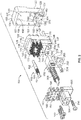
- FIG. 2 is a rear exploded view of the connector assembly 100 showing the coaxial connector module 102 and the fiber optic module 104.
- Figure 3 is a front exploded view of the connector assembly 100 showing the coaxial connector module 102 and the fiber optic module 104.
- the connector body 126 includes a forward section 140 and a rear section 142.
- the forward and rear sections 140, 142 are discrete elements that are configured to be secured to each other.
- the forward and rear sections 140, 142 are secured to each other using hardware 143 (e.g., screws), but may be secured to each other in other manners in alternative embodiments.
- the hardware 143 are captive screws configured to be held in the rear section 142, such as to make assembly easier and/or to prevent losing the hardware 143 during assembly.
- the forward section 140 includes a main portion 144 and a flange portion 145 that extends laterally (or radially) away from the main portion 144.
- the flange portion 145 may be defined by a first lip 146 and a second lip 147 at opposite first and second sides 148, 149.
- the flange portion 145 may include other lips in alternative embodiments, such as a lip along the top and/or the bottom.
- the flange portion 145 is provided at the front side 127 of the connector body 126.
- the lips 146, 147 may include rearward-facing surfaces facing in the mounting direction.
- the mounting frame 106 includes a connector-receiving recess 150 of the passage 120 that opens along the mounting side 108 to receive the connector body 126.
- the recess 150 includes a first cavity 151 at a first side 152 of the mounting frame 140 and a second cavity 153 and a second side 154 of the mounting frame 140.
- the connector-receiving recess 150 is sized and shaped to receive the main portion 144 of the connector body 126 and the cavities 151, 153 are sized and shaped to receive the flange portion 145, such as the first lip 146 and the second lip 147, respectively.
- the first cavity 151 is defined by a front rim 155 at the mating side 107 and a rear rim 156 at the mounting side 108.
- the first cavity 151 includes a cavity wall 157 between the front rim 155 and the rear rim 156 at the first end of the recess 150.
- the first cavity 151 is open at the first side of the recess 150 and is closed or blocked by the front rim 155, the rear rim 156 in the cavity wall 157.
- the second cavity 153 is defined by a front rim 158 at the mating side 107 and a cavity wall 159 opposite the cavity wall 157.
- the second cavity 153 is open at the mounting side 108, such as for loading the connector body 126 into the recess 150.
- the connector-receiving recess 150 is defined by blocking surfaces 160 used to block or retain the coaxial connector module 102 and the mounting frame 106.
- the blocking surfaces 160 may limit or restrict movement of the coaxial connector module 102 in an axial direction along the mating axis 191.
- the blocking surfaces 160 may limit or restrict movement of the coaxial connector module 102 in a lateral direction along the lateral axis 192 and/or the lateral axis 193.
- the blocking surfaces 160 are defined by the front rim 155, the rear rim 156, the cavity wall 157, the front rim 158 and the cavity wall 159.
- the mounting frame 106 may include additional blocking surfaces 160 in alternative embodiments, such as blocking surfaces 160 defined by the top and the bottom of the recess 150.
- the blocking surfaces 160 include front blocking surfaces, rear blocking surfaces and end blocking surfaces.
- the front blocking surfaces limit or restrict movement in the mating direction.
- the rear blocking surfaces 160 to limit or restrict movement in the mounting direction.
- the end blocking surfaces limit or restrict movement in the lateral direction.
- the front rims 155, 158 define the front blocking surfaces
- the rear rim 156 defines the rear blocking surface and the cavity walls 157, 159 and the top and the bottom define the end blocking surfaces.
- the end blocking surfaces face in the lateral direction that is perpendicular to the mating axis 191 to limit or restrict movement in the lateral direction.
- the recess 150 may be oversized to allow a limited amount of floating movement in the lateral direction.
- the end blocking surfaces may be wider than the connector body 126 to allow shifting in at least one of the lateral directions 192, 193.
- the end blocking surfaces may permit the coaxial connector module 102 to float at least 0.15 mm along a lateral plane.
- the coaxial connector module 102 may be permitted to float at least 0.25 mm or, more particularly, at least 0.35 mm along the lateral plane. It should be understood, however, that the connector assembly 100 may be configured to permit a greater or lesser amount of floating than the values provided above. The amount of floating movement may be controlled based on manufacturing tolerances of the connector assemblies 100, 300.
- the first lip 146 of the flange portion 145 is configured to be retained or trapped between the front and rear rims 155, 156 of the mounting frame 106.
- the blocking surfaces 160 may limit axial movement.
- the coaxial connector module 102 may have a limited amount of floating movement in the axial direction between the front and rear rims 155, 156.
- the first lip 146 may have a tight fit between the front and rear rims 155, 156 such that there is no movement in the axial direction.
- the connector assembly 100 includes a backing plate 200 configured to be coupled to the mounting frame 106.
- the backing plate 200 is used to secure the coaxial connector module 102 and the recess 150.
- the mounting frame 106 includes a plate pocket 202 at the mounting side 108, such as at the second side 154.
- the plate pocket 202 is sized and shaped to receive the backing plate 200.
- the backing plate 200 may be loaded into the plate pocket 202 from behind the mounting frame 106.
- the backing plate 200 may be loaded into the plate pocket 202 from the side, such as from the exterior side of the mounting frame 106 or from the interior side in the recess 150.
- the backing plate 200 may be secured to the mounting frame 106, such as using a fastener 204. Other securing means may be used in alternative embodiments.
- an inner edge 208 of the backing plate 200 may extend into the recess 150 to overlap and retain the coaxial connector module 102 in the recess 150.
- the backing plate 200 includes a blocking surface 210 that defines a rear blocking surface for the coaxial connector module 102.
- the inner edge 208 is configured to be positioned rearward of the second cavity 153.
- the backing plate 200 may be positioned rearward of the connector body 126, such as rearward of the second lip 147 to restrict or block removal of the coaxial connector module 102 from the recess 150.
- the backing plate 200 is used to contain the coaxial connector module 102 and the mounting frame 106 such that the coaxial connector module 102 and the mounting frame 106 may be mounted to the support wall 110 as a unit.
- the coaxial connector module 102 may be held in the mounting frame 106 using the backing plate 200 without the need for the support wall 110 to hold the coaxial connector module 102 in the mounting frame 106.
- the forward section 140 and the rear section 142 of the connector body 126 are coupled together using the fasteners 143.
- the forward section 140 includes a plurality of contact cavities 172
- the rear section 142 includes a plurality of contact cavities 182.
- the contact cavities 172 of the forward section 140 and the contact cavities 182 of the rear section 142 align with each other to form contact channels 184 (shown in Figure 5 ).
- Each of the contact channels 184 is configured to receive a portion of a corresponding coaxial cable assembly 128 and, in particular, a corresponding coaxial contact 132.
- the contact cavities 182 may open to an outer edge to define open-sided slots sized and shaped to receive the cables 131 of the coaxial cable assemblies 128.
- the contact cavities 182 may include ledges 186, such as at the rear of the rear section 142, that are used to support the springs of the cable assemblies 128.
- the coaxial cable assemblies 128 include biasing springs 133 configured to be coupled between the connector body 126 and the coaxial contact 132 to allow floating movement of the coaxial contacts 132 in the contact channels 184.
- the biasing springs 133 are received in corresponding contact channels 184.
- the biasing springs 133 may engage the coaxial contacts 132 and may engage the ledges 186 at the rear of the rear section 142.
- the connector assembly 100 is mated with the connector assembly 300, the coaxial contacts 132 may be compressed and pushed rearward.
- the biasing springs 133 may allow the coaxial contacts 132 to move axially rearward.
- the biasing springs 133 provided biasing force for mating the coaxial contacts 132 with the mating contacts 324 of the connector assembly 300.
- the forward section 140 includes alignment channels 174 that extend entirely through the forward section 140.
- the alignment channels 174 are configured to receive alignment posts 176 that are configured to clear the front side 127 and the passage 120 and project away from the mounting frame 106 in the mating direction.
- the alignment posts 176 are configured to engage the mating connector 302 (shown in Figure 1 ) during the mating operation.
- the connector assembly 100 includes two alignment posts 176. In other embodiments, however, the connector assembly 100 may include only one alignment post 176 or more than two alignment posts 176.
- the connector body 126 has a first side 244 and a second side 246 opposite the first side 244 extending between the front side 127 and the rear side 129.
- the connector body 126 has a first end 248 and a second end 249 opposite the first end 248 extending between the front side 127 and the rear side 129.
- the connector body 126 has a mating interface 250 for mating with the fiber optic module 104.
- the mating interface 250 is provided at the rear side 129; however, other locations are possible in alternative embodiments.
- the connector body 126 includes a pocket 252 defining the mating interface 250.
- the pocket 252 may be defined rearward of the rear side 129 of the forward section 140 of the connector body 126 and below the rear section 142 of the connector body 126. A portion of the pocket 252 may extend into the forward section 140.
- the pocket 252 receives a portion of the fiber optic module 104.
- the fiber optic module 104 may be nested in the pocket 252 of the connector body 126.
- the pocket 252 may be open at the rear side 129 and/or may be open at the first side 244 and/or the second side 246 and/or the 2 nd end 249.
- the forward portion of the pocket 252 may be enclosed by the connector body 126.
- the connector body 126 includes fastener openings 254 open to the mating interface 250 that receive fasteners 256 used to secure the fiber optic module 104 to the connector body 126.
- the fastener openings 254 are open at the rear side 129; however, other locations are possible in alternative embodiments, such as at the second end 249.
- the connector body includes a window 258 at the front side 127 open to the mating interface 250.
- the window 258 defines a passage through the connector body 126 between the front side 127 and the rear side 129.
- the window 258 receives a portion of the fiber optic module 104 such that the fiber optic module 104 is presented at the mating end for mating with the connector assembly 100.
- the connector body 126 may encase the window 258 such that the connector body 126 extends entirely around the fiber optic module 104 at the mating end.
- the fiber optic module 104 may extend entirely through the window 258 beyond the front side 127 for mating with the connector assembly 100.
- the fiber optic module 104 includes a housing 500 holding a fiber optic connector 502.
- the housing 500 is configured to be coupled to the connector body 126.
- the housing 500 includes a cavity 504 receiving the fiber optic connector 502.
- the housing 500 is coupled to the connector body 126 at the mating interface 250.
- the housing 500 may be received in the pocket 252 and secured in the pocket 252 by the fasteners 256.
- the fasteners 256 create a rigid mechanical connection between the connector body 126 and the housing 500.
- the fiber optic module 104 is coupled to the coaxial connector module 302 such that the fiber optic connector 502 is aligned with and received in the window 258.
- the fiber optic connector 502 extends through the coaxial connector module 302 for mating with the connector assembly 100.
- the fiber optic module 104 includes a biasing spring 506 configured to be coupled between the housing 500 and the fiber optic connector 502 to allow floating movement of the fiber optic connector 502 in the cavity 504.
- the biasing spring 506 may engage the housing 500 at the rear of the cavity 504.
- the fiber optic connector 502 may be compressed and pushed rearward.
- the biasing spring 506 allows the fiber optic connector 502 to move axially rearward.
- the biasing springs 506 provides biasing force for mating the fiber optic connector 502 with the mating fiber optic connector 402 (shown in Figure 1 ) of the connector assembly 300.
- Figure 4 is a rear perspective view of the connector assembly 100 in an assembled state showing the coaxial connector module 102 and the fiber optic module 104.
- Figure 5 is a front perspective view of the connector assembly 100 in an assembled state showing the coaxial connector module 102 and the fiber optic module 104.
- the fiber optic module 104 is shown coupled to the coaxial connector module 102.
- the housing 500 is coupled to the mating interface 250 of the connector body 126.
- the fiber optic connector 502 is held in the housing 500 and a mating end 508 of the fiber optic connector 502 is received in the window 258 for mating with the fiber optic connector 402 (shown in Figure 1 ).
- the fiber optic connector 502 includes a ferrule 510 at the mating end 508.
- the ferrule 510 may hold fibers for transmitting light.
- a fiber optic cable 512 extends from the fiber optic connector 502.
- the fiber optic cable 512 extends rearward of the housing 500.
- the fiber optic connector 502 includes guide features 514 extending forward of the ferrule 510 to guide mating with the fiber optic connector 402.
- the connector assembly 100 includes the RF connector interface defined by the coaxial contacts 132 and the fiber optic connector interface defined by the fiber optic connector 502. Both interfaces are presented within the same connector assembly 100.
- the mating end 508 of the fiber optic connector 502 is located immediately adjacent the array of coaxial contacts 132.
- the mating ends of the coaxial contacts 132 and the mating end 508 of the fiber optic connector 502 are presented at the front side 127 of the connector body 126.
- the alignment post 176 extend forward of the front side 127 of the connector body 126.
- the alignment posts 176 extend further forward than the coaxial contacts 132 and the fiber optic connector 502 such that the alignment posts 176 are used to align the interfaces prior to mating with the connector assembly 300 (shown in Figure 1 ).
- the alignment posts 176 define guide features for guiding mating with the connector assembly 300.
- the window 258 and the fiber optic connector 502 are located between the alignment posts 176 and the coaxial contacts 132.
- the alignment posts 176 are provided near the bottom of the connector body 126
- the coaxial contacts 132 are provided near the top of the connector body 126
- the fiber optic connector 502 is provided near the center of the connector body 126.
- Other arrangements are possible in alternative embodiments.
- the connector body 126 has a perimeter defined by the ends 248, 249 and the sides 244, 246.
- the coaxial contacts 132 are arranged in an array within the perimeter of the connector body 126.
- the window 258 is contained within the perimeter such that the mating end 508 of the fiber optic connector 502 is contained within the perimeter.
- the window 258 is encased by the connector body 126 such that the connector body 126 extends entirely around the ferrule 510 of the fiber optic connector 502.
- the connector body 126 holds the biasing springs 133 in the contact channels 184 engaging the corresponding coaxial contacts 132 to allow axial compression of the coaxial contacts 132 when mated with the coaxial contacts 324 (shown in Figure 1 ).
- the housing 500 holds the biasing spring 506 in the cavity 504 engaging the fiber optic connector 502 to allow axial compression of the fiber optic connector 502 when mated with the fiber optic connector 402.
- the mounting frame 106 surrounds the connector body 126 and the fiber optic module 104.
- the connector body 126 is received in the recess 150 and holds the fiber optic connector 502 in the recess 150.
- the recess 150 is oversized relative to the connector body 126 to allow a limited amount of floating movement of the connector body 126 in the recess 150 within the confined space defined by blocking surfaces of the mounting frame 106 to allow relative movement of the connector body 126 and the fiber optic module 104 for mating with the connector assembly 300.
- the coaxial cables 131 and the fiber optic cable 512 extend rearward from the connector assembly 100 and are configured to pass through the support wall 110 (shown in Figures 1 and 10 ).
- Figure 6 is a rear exploded view of the connector assembly 300 showing the coaxial connector module 302 and the fiber optic module 304.
- Figure 7 is a front exploded view of the connector assembly 300 showing the coaxial connector module 302 and the fiber optic module 304.
- Figure 8 is a rear perspective view of the connector assembly 300 in an assembled state showing the coaxial connector module 302 and the fiber optic module 304.
- Figure 9 is a front perspective view of the connector assembly 300 in an assembled state showing the coaxial connector module 302 and the fiber optic module 304.
- the coaxial connector module 302 includes the connector body 310 holding the coaxial cable assemblies 320.
- the connector body 310 includes a forward section 360 and a rear section 362.
- the forward and rear sections 360, 362 are discrete elements that are configured to be secured to each other.
- the forward and rear sections 360, 362 are secured to each other using hardware 363 (e.g., screws), but may be secured to each other in other manners in alternative embodiments.
- the hardware 343 are captive screws configured to be held in the rear section 362, such as to make assembly easier and/or to prevent losing the hardware 343 during assembly.
- the forward section 360 includes a plurality of contact cavities 364 and the rear section 362 includes a plurality of contact cavities 366.
- each of the contact channels 368 is configured to receive a portion of a corresponding coaxial cable assembly 320 and, in particular, a corresponding coaxial contact 324.
- the connector body 310 has the mating interface 350, which in the illustrated embodiment includes the pocket 352.
- the pocket 352 receives the housing 400 of the fiber optic module 304.
- the front end of the housing 400 may be nested in the pocket 352 of the connector body 310.
- the front end of the housing 400 includes fastener openings 408 that are configured to be aligned with the fastener openings 354 of the connector body 310 to receive the fasteners 356.
- the fasteners 356 secure the housing 400 of the fiber optic module 304 to the connector body 310.
- the fiber optic connector 402 is aligned with and at least partially received in the window 358.
- the connector body 310 encases the window 358 such that the connector body 310 extends entirely around the fiber optic connector 402.
- the fiber optic connector 402 is received in the cavity 404 of the housing 400.
- the housing 400 is securely coupled to the connector body 310 at the mating interface 350 and is configured to be securely coupled to the substrate 306.
- the fiber optic connector 402 includes a ferrule 410 at the mating end of the fiber optic connector 402.
- the ferrule 410 may hold fibers for transmitting light.
- the fiber optic module 304 is configured to be terminated to the substrate 306.
- the fiber optic module 304 may include a digital to optical converter or other componentry for connection to the substrate 306.
- a fiber optic cable (not shown) may extend from the fiber optic connector 402.
- the connector assembly 300 includes the RF connector interface defined by the coaxial contacts 324 and the fiber optic connector interface defined by the fiber optic connector 402. Both interfaces are presented within the same connector assembly 300.
- the mating end of the fiber optic connector 402 is located immediately adjacent the array of coaxial contacts 324.
- the mating ends of the coaxial contacts 324 and the mating end of the fiber optic connector 402 are presented at the front side 340 of the connector body 310.
- the alignment features 318 are provided at the front side 340 of the connector body 310 for receiving the alignment posts. Other types of guide features may be provided in alternative embodiments.
- the window 358 and the fiber optic connector 402 are located between the alignment features 318 and the coaxial contacts 324. Other arrangements are possible in alternative embodiments.
- the connector body 310 has a perimeter defined by the ends 348, 349 and the sides 344, 346.
- the coaxial contacts 324 are arranged in an array within the perimeter of the connector body 310.
- the window 358 is contained within the perimeter such that the ferrule 410 of the fiber optic connector 402 is contained within the perimeter.
- the window 358 is encased by the connector body 310 such that the connector body 310 extends entirely around the ferrule 410 of the fiber optic connector 402.
- Figure 10 is a rear perspective view of a portion of the communication system 10 showing the connector assembly 100 coupled to the support wall 110.
- the support wall 110 includes an opening 220.
- the connector assembly 100 is coupled to the support wall 110 at the opening 220.
- the mounting frame 106 is securely coupled to the support wall 110 using fasteners 222 or other means.
- the mounting side 108 abuts against a front surface 224 of the support wall 110.
- the mounting frame 106 supports the coaxial connector module 102 and the fiber optic module 104 independent of the support wall 110.
- the backing plate 200 holds the connector body 126 in the mounting frame 106 such that no portion of the connector body 126 engages the support wall 110.
- the opening 220 may be oversized relative to the coaxial connector module 102.
- the coaxial connector module 102 and the fiber optic module 104 held by the connector body 126 has a limited amount of floating movement relative to the support wall 110.
- portions of the coaxial connector module 102 and the fiber optic module 104 extend into and/or through the opening 220.
- the rear section 142 may extend into and/or through the opening 220.
- the coaxial cables 131 extend through the opening 220 and extend from the support wall 110, such as to another component.
- the fiber optic cable 512 extends through the opening 220 and extends from the support wall 110, such as to another component.
- Figure 11 is a cross-sectional view of the communication system 10 showing the connector assembly 100 mated with the connector assembly 300 at the mating side 107.
- the connector assembly 100 is mounted to the support wall 110 at the mounting side 108.
- the rear portion of the front section 140 and the rear section 142 extend into the opening 220 of the support wall 110.
- the mounting frame 106 rests on the front surface 224 of the support wall 110.
- the backing plate 200 holds the connector body 126 in the recess 150 such that the connector body 126 is supported by the mounting frame 106 and the backing plate 200 independent of the support wall 110.
- the recess 150 may be open at the mounting end 114 and the support wall 110 may be used to hold the connector body 126 in the recess 150 at the mounting end 114.
- the connector body 126 supports the fiber optic module 104.
- the coaxial connector module 102 has a limited amount of floating movement relative to the mounting frame 106.
- the recess 150 is oversized relative to the connector body 126.
- gaps are provided between the connector body 126 and the mounting frame 106.
- the connector body 126 is able to shift laterally in the recess 150.
- the mounting frame 106 and the backing plate 200 form a confined space for the connector body 126 to generally hold the connector body 126 and the fiber optic module 104 while allowing the floating movement within the confined space, such as in one or more directions.
- the blocking surfaces 160, 210 define the confined space.
- the confined space represents the limited space in which the portion of the coaxial connector module 102 is permitted to move relative to the support wall 110 or the mounting frame 106.
- the coaxial cable assemblies 128 include the biasing springs 133 coupled to the connector body 126 to allow floating movement of the coaxial contacts 132 in the contact channels 184.
- the biasing springs 133 engage the coaxial contacts 132 and engage the ledges 186 at the rear of the rear section 142.
- the biasing springs 133 allow the coaxial contacts 132 to move axially rearward and provide a biasing force for mating the coaxial contacts 132 with the mating contacts 324 of the connector assembly 300.
- the biasing force facilitates maintaining a sufficient electrical connection between the coaxial contacts 132 and the coaxial contacts 324.
- the communication system 10 may experience shock, vibration, and/or extreme temperatures that may cause deformation, movement, and/or creepage among different elements.
- the biasing force may lengthen or improve the lifetime operability of the communication system 10.
- the fiber optic module 104 includes the biasing spring 506 coupled to the housing 500 to allow floating movement of the fiber optic connector 502 in the cavity 504.
- the biasing spring 506 engages the fiber optic connector 502 and engages the housing 500 at the rear of the cavity 504.
- the biasing spring 506 allows the fiber optic connector 502 to move axially rearward and provide a biasing force for mating the fiber optic connector 502 with the mating fiber optic connector 402 of the connector assembly 300.
- Figure 12 is a perspective view of the communication system 10 formed in accordance with an exemplary embodiment, showing the connector assembly 100 and the connector assembly 300 in an unmated state.
- Figure 12 shows a different arrangement of the alignment posts 176 and the alignment features 318, showing the alignment posts 176 and the alignment features 318 more centrally located, such as within the array of the coaxial contacts 132 and 324.
- the connector bodies 126, 310 may be shorter by moving the alignment posts 176 and the alignment features 318.
- Figure 12 shows a different arrangement for connecting the connector body 310 to the housing 400.
- the fasteners 356 are coupled to the bottom of the connector body 310 rather than the front of the connector body 310.
- the fastener 356 are fastened in a direction perpendicular to the substrate 306 rather than parallel to the substrate 306.
- Figure 13 is a front perspective view of the connector assembly 100 in an assembled state showing the coaxial connector module 102 and the fiber optic module 104 from the embodiment shown in Figure 12 .
- Figure 14 is a rear perspective view of the connector assembly 100 in an assembled state showing the coaxial connector module 102 and the fiber optic module 104 from the embodiment shown in Figure 12 .
- Figure 15 is a rear exploded view of the connector assembly 100 showing the coaxial connector module 102 and the fiber optic module 104 from the embodiment shown in Figure 12 .
- the rear section 142 of the connector body 126 is formed integral with the housing 500.
- the housing 500 is mounted to the front section 140 of the connector body 126 with the rear section 142 using the fasteners 143.
- the housing 500 may be separate and discrete from the rear section 142.
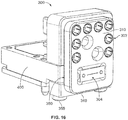
- Figure 16 is a front perspective view of the connector assembly 300 in an assembled state showing the coaxial connector module 302 and the fiber optic module 304 from the embodiment shown in Figure 12 .
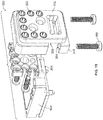
- Figure 17 is a rear perspective view of the connector assembly 300 in an assembled state showing the coaxial connector module 302 and the fiber optic module 304 from the embodiment shown in Figure 12 .
- Figure 18 is a front exploded view of the connector assembly 300 showing the coaxial connector module 302 and the fiber optic module 304 from the embodiment shown in Figure 12 .
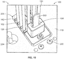
- Figure 19 is a rear exploded view of the connector assembly 300 showing the coaxial connector module 302 and the fiber optic module 304 from the embodiment shown in Figure 12 .
- the fastener openings 354 in the connector body 310 are open to the mating interface 350 to receive the fasteners 356 to secure the fiber optic module 304 to the connector body 310.
- the fastener openings 354 are open at the second end 349. The fasteners 356 are secured to the bottom of the housing 400 rather than the front of the housing 400.
- Figure 20 is a front exploded view of the connector assembly 300 showing the coaxial connector module 302 and the fiber optic module 304 similar to the embodiment shown in Figure 18 .
- Figure 20 shows the fastener openings 354 at the front side 340 of the connector body 310 to receive the fasteners 356 from the front rather than from the bottom.
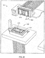
- Figure 21 is a perspective view of the communication system 10 formed in accordance with an exemplary embodiment, showing the connector assembly 100 and the connector assembly 300 in an unmated state.
- Figure 21 shows a different type of alignment post 176 and alignment feature 318, showing the alignment post 176 as an elongated tab rather than a pair of posts.
- the alignment post 176 and the alignment features 318 are centrally located within the array of the coaxial contacts 132 and 324.
- the connector assemblies 100, 300 include a greater number of coaxial contacts 132, 324 and the connector assemblies 100, 300 have a larger mating interface as compared to the embodiments shown in Figure 1 and 12 .
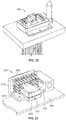
- Figure 22 is a front perspective view of the connector assembly 100 in accordance with an exemplary embodiment.
- Figure 23 is a rear perspective view of the connector assembly 300 in accordance with an exemplary embodiment.
- the connector body 310 includes mounting beams 370 at the rear side of the connector body 310 for mounting the connector body 310 to the substrate 306.
- the connector body 310 is configured to be separately mounted to the substrate 306 over the fiber optic module 304.
- the mating end of the fiber optic module 304 is loaded into the connector body 310, such as into the pocket of the connector body 310 such that the ferrule 410 of the fiber optic connector 402 extends through the window 358 at the front side 340 of the connector body 310.
- the fiber optic module 304 separately mounted to the substrate 306.
- the fiber optic module 304 may be mounted to the substrate 306 prior to the connector body 310.
- the connector body 310 may be placed over and around the fiber optic module 304 such that the mating end of the fiber optic connector 402 extends through the window 358 for mating with the connector assembly 100.
- Figure 24 is an exploded view of the connector assembly 300 in accordance with an exemplary embodiment.
- Figure 24 shows the fiber optic module 304 including a housing 600 holding a fiber optic connector 602 provided at an end of a fiber optic cable 612, rather than utilizing the board mounted housing 400 and fiber optic connector 402 shown in Figure 1 .
- the housing 600 is configured to be coupled to the connector body 310.
- the housing 600 includes a cavity 604 receiving the fiber optic connector 602.
- the fiber optic module 304 is arranged for coupling with the fiber optic connector 502 of the coaxial connector module 302 (shown in Figure 1 ).
- the fiber optic module 304 includes a biasing spring 606 configured to be coupled between the housing 600 and the fiber optic connector 602 to allow floating movement of the fiber optic connector 602 in the cavity 604.
Landscapes
- Physics & Mathematics (AREA)
- General Physics & Mathematics (AREA)
- Optics & Photonics (AREA)
- Mechanical Coupling Of Light Guides (AREA)
- Details Of Connecting Devices For Male And Female Coupling (AREA)
- Coupling Device And Connection With Printed Circuit (AREA)
Abstract
Description
- The subject matter described and/or illustrated herein relates generally to communication systems having connector assemblies.
- Connector assemblies are known for interconnecting various components. Some communication systems include different types of connector assemblies having different interfaces. For example, some known communication systems incorporate coaxial connectors and fiber optic connectors within the system. Typically, the coaxial connectors are mounted to one area of the circuit board and the fiber optic connectors are mounted to a different area of the circuit board. As one example, a backplane communication system may include a large backplane circuit board that includes one or more coaxial connectors and one or more fiber optic connectors for mating with corresponding coaxial connectors and fiber optic connectors of a daughter card assembly or assemblies. The coaxial connectors and the fiber optic connectors are typically spread along a mating edge of the backplane circuit board. The coaxial connectors and the fiber optic connectors each occupy a separate footprint of the backplane circuit board. The number and type of connectors that may be provided within a given board area is limited.
- Accordingly, there is a need for a communication system having high density of connections.
- The solution is provided by a connector assembly including a coaxial connector module and a fiber optic module coupled to the coaxial connector module. The coaxial connector module includes a connector body and coaxial contacts. The connector body extends between a front side and a rear side. The connector body has contact channels therethrough holding corresponding coaxial contacts for engaging corresponding mating coaxial contacts of a mating connector assembly. The front side faces in a mating direction along a mating axis. The connector body has a mating interface and fastener openings open at the mating interface to receive fasteners. The connector body has a window at the mating interface. The fiber optic module includes a housing coupled to the mating interface of the connector body. The housing has a cavity and fastener openings aligned with the fastener openings in the connector body and receiving the fasteners to couple the housing to the connector body at the mating interface. The fiber optic module includes a fiber optic connector received in the cavity of the housing. The fiber optic connector has a mating end and a fiber optic cable extending from the fiber optic connector. The fiber optic connector is received in the window for mating with a mating fiber optic connector of the mating connector assembly.
- The invention will now be described by way of example with reference to the accompanying drawings in which:
-
Figure 1 is a perspective view of a communication system formed in accordance with an exemplary embodiment showing a connector assembly and a connector assembly in an unmated state. -
Figure 2 is a rear exploded view of the connector assembly in accordance with an exemplary embodiment showing a coaxial connector module and a fiber optic module. -
Figure 3 is a front exploded view of the connector assembly showing the coaxial connector module and the fiber optic module. -
Figure 4 is a rear perspective view of the connector assembly in an assembled state showing the coaxial connector module and the fiber optic module. -
Figure 5 is a front perspective view of the connector assembly in an assembled state showing the coaxial connector module and the fiber optic module. -
Figure 6 is a rear exploded view of the connector assembly showing the coaxial connector module and the fiber optic module. -
Figure 7 is a front exploded view of the connector assembly showing the coaxial connector module and the fiber optic module. -
Figure 8 is a rear perspective view of the connector assembly in an assembled state showing the coaxial connector module and the fiber optic module. -
Figure 9 is a front perspective view of the connector assembly in an assembled state showing the coaxial connector module and the fiber optic module. -
Figure 10 is a rear perspective view of a portion of the communication system showing the connector assembly coupled to a support wall. -
Figure 11 is a cross-sectional view of the communication system showing the connector assembly mated with the connector assembly. -
Figure 12 is a perspective view of the communication system formed in accordance with an exemplary embodiment, showing the connector assembly and the connector assembly in an unmated state. -
Figure 13 is a front perspective view of the connector assembly in an assembled state showing the coaxial connector module and the fiber optic module. -
Figure 14 is a rear perspective view of the connector assembly in an assembled state showing the coaxial connector module and the fiber optic module. -
Figure 15 is a rear exploded view of the connector assembly showing the coaxial connector module and the fiber optic module. -
Figure 16 is a front perspective view of the connector assembly in an assembled state showing the coaxial connector module and the fiber optic module. -
Figure 17 is a rear perspective view of the connector assembly in an assembled state showing the coaxial connector module and the fiber optic module. -
Figure 18 is a front exploded view of the connector assembly showing the coaxial connector module. -
Figure 19 is a rear exploded view of the connector assembly showing the coaxial connector module and the fiber optic module. -
Figure 20 is a front exploded view of the connector assembly showing the coaxial connector module and the fiber optic module. -
Figure 21 is a perspective view of the communication system formed in accordance with an exemplary embodiment showing the connector assembly and the connector assembly in an unmated state. -
Figure 22 is a front perspective view of the connector assembly in accordance with an exemplary embodiment. -
Figure 23 is a rear perspective view of the connector assembly in accordance with an exemplary embodiment. -
Figure 24 is an exploded view of a connector assembly in accordance with an exemplary embodiment. - In an embodiment, a connector assembly is provided including a coaxial connector module and a fiber optic module coupled to the coaxial connector module. The coaxial connector module includes a connector body and coaxial contacts. The connector body extends between a front side and a rear side. The connector body has contact channels therethrough holding corresponding coaxial contacts for engaging corresponding mating coaxial contacts of a mating connector assembly. The front side faces in a mating direction along a mating axis. The connector body has a mating interface and fastener openings open at the mating interface to receive fasteners. The connector body has a window at the mating interface. The fiber optic module includes a housing coupled to the mating interface of the connector body. The housing has a cavity and fastener openings aligned with the fastener openings in the connector body and receiving the fasteners to couple the housing to the connector body at the mating interface. The fiber optic module includes a fiber optic connector received in the cavity of the housing. The fiber optic connector has a mating end and a fiber optic cable extending from the fiber optic connector. The fiber optic connector is received in the window for mating with a mating fiber optic connector of the mating connector assembly.
- In another embodiment, a connector assembly is provided including a coaxial connector module and a fiber optic module coupled to the coaxial connector module. The coaxial connector module includes a connector body and coaxial contacts. The connector body extends between a front side and a rear side. The connector body has contact channels therethrough holding corresponding coaxial contacts for engaging corresponding mating coaxial contacts of a mating connector assembly. The front side faces in a mating direction along a mating axis. The connector body has a mating interface and fastener openings at the mating interface to receive fasteners. The connector body has a window at the mating interface. The fiber optic module is coupled to the coaxial connector module. The fiber optic module includes a housing coupled to the mating interface of the connector body. The housing has a cavity and fastener openings aligned with the fastener openings in the connector body and receiving the fasteners to couple the housing to the connector body at the mating interface. The fiber optic module includes a fiber optic connector received in the cavity of the housing. The fiber optic connector has a mating end and a fiber optic cable extending from the fiber optic connector. The fiber optic connector is received in the window for mating with a mating fiber optic connector of the mating connector assembly. The connector assembly includes a mounting frame having a mating side and a mounting side that face in opposite directions. The mounting side faces in a mounting direction along the mating axis and configured to interface with a support wall. The mounting frame defines a passage therethrough having a recess that receives the connector body. The mounting frame has a plate pocket at the mounting side open to the recess and a backing plate is removably received in the plate pocket. The backing plate is coupled to the mounting frame to at least partially block the recess at the mounting side. The mounting frame includes blocking surfaces and the backing plate includes a blocking surface. The blocking surfaces of the mounting frame and the blocking surface of the backing plate defining a confined space oversized relative to the connector body to allow a limited amount of floating movement of the connector body and the fiber optic module held by the connector body in the confined space in a lateral direction that is perpendicular to the mating axis.
- In a further embodiment, a communication system is provided including a first connector assembly and a second connector assembly coupled to the first connector assembly. The first connector assembly includes a first coaxial connector module and a first fiber optic module coupled to the first coaxial connector module. The first coaxial connector module has a first connector body and first coaxial contacts held by the first connector body. The first connector body has a first mating interface and first fastener openings at the first mating interface to receive first fasteners. The first connector body has a first window open at the first mating interface. The first fiber optic module includes a first housing coupled to the first mating interface of the first connector body and secured thereto by the first fasteners. The first housing has a first cavity receiving a first fiber optic connector having a mating end received in the window. The second connector assembly includes a second coaxial connector module and a second fiber optic module coupled to the second coaxial connector module. The second coaxial connector module has a second connector body and second coaxial contacts held by the second connector body. The second coaxial contacts have biasing springs coupled to the second connector body to allow floating movement when mated to the first coaxial contacts. The second connector body has a second mating interface and second fastener openings at the second mating interface receiving second fasteners. The second connector body has a second window at the second mating interface. The second fiber optic module includes a second housing coupled to the second mating interface and secured thereto by the second fasteners. The second housing has a second cavity receiving a second fiber optic connector having a mating end received in the window the second fiber optic module having a biasing spring coupled to the second housing and the second fiber optic connector to allow floating movement of the second fiber optic connector when mated to the first fiber optic connector.
- Embodiments set forth herein include connector assemblies and communication systems that include such connector assemblies. The communication system may include, for example, a circuit board that is secured to the connector assembly. In some embodiments, the communication system is a backplane (or midplane) communication system. As used herein, the terms backplane and midplane are used interchangeably and represent a system interface for multiple daughter card assemblies (e.g., line cards or switch cards). In other embodiments, the communication system is a circuit board assembly (e.g., daughter card assembly). One or more embodiments permit a coaxial connector module of the connector assembly to float during a mating operation. One or more embodiments enable using a denser grouping of coaxial contacts by permitting the coaxial contacts to be rear-loaded into the coaxial connector module. In particular embodiments, the coaxial connector module is permitted to float and also enables rear-loading of coaxial contacts.
- As used herein, phrases such as "a plurality of [elements]," "a set of [elements]," "an array of [elements]," and the like, when used in the detailed description and claims, do not necessarily include each and every element that a component may have. For instance, the phrase "the coaxial connector module having a plurality of coaxial contacts that include [a recited feature]" does not necessarily mean that each and every coaxial contact of the coaxial connector module has the recited feature. Instead, only some of the coaxial contacts may have the recited feature and other coaxial contacts of the coaxial connector module may not include the recited feature. As another example, the detailed description or the claims may recite that a connector assembly includes "a cable assemblies, each of which including a [recited feature]." This phrase does not exclude the possibility that other cable assemblies of the connector assembly may not have the recited feature. Accordingly, unless explicitly stated otherwise (e.g., "each and every cable assembly of the coaxial connector module"), embodiments may include similar elements that do not have the same features.
-
Figure 1 is a perspective view of acommunication system 10 formed in accordance with an exemplary embodiment, showing aconnector assembly 100 and aconnector assembly 300 in an unmated state. Theconnector assemblies connector assemblies connector assembly common connector assembly - In some applications, the
connector assemblies communication system 10 may be performed by RF connectors configured for radiofrequency (RF) applications. In particular embodiments, thecommunication system 10 and/or its components, such as theconnector assembly 100 and/or 300, are configured to satisfy military and aerospace applications. For example, the components of thecommunication system 10 may be configured to satisfy one or more industry or government standards, such as MIL-STD-348. To illustrate one example of thecommunication system 10, theconnector assemblies connector assembly 300 may perform analog functions. Theconnector assembly 300 may be replaced with other connector assemblies that are configured to perform the same or different operations. The digital functions, including digital signal processing, may be performed by a communication component (not shown) that is coupled to theconnector assembly 100. The other communication component may be another daughter card assembly (not shown). - The
communication system 10 and/or its components (e.g., theconnector assembly 100 and/or 300) may be configured to satisfy one or more industry or government standards. By way of example only, embodiments may be configured to satisfy the VME International Trade Association (VITA) standards (e.g., VITA 48, VITA 67, et al.). Thecommunication system 10 and/or its components may have an operating speed that achieves 50 GHz or greater. In particular embodiments, thecommunication system 10 and/or its components may achieve an operating speed of 60 GHz or greater. It should be understood, however, that other embodiments may be configured for different standards and may be configured to operate at different speeds. In some configurations, embodiments may be configured to operate within the range of DC to 60.0 GHz. - In an exemplary embodiment, the
connector assembly 300 is a daughter card assembly having acoaxial connector module 302 and afiber optic module 304 mounted to asubstrate 306. Thecoaxial connector module 302 and thefiber optic module 304 are mounted to thesubstrate 306 as part of a common connector. Thesubstrate 306 may be a circuit card, such as a daughter card. Theconnector assembly 300 includes a guide module or guidemodules 308 mounted to thesubstrate 306 proximate to thecoaxial connector module 302 and/or thefiber optic module 304. Theguide module 308 is used to guide mating with theconnector assembly 100. In the illustrated embodiment, theguide module 308 includes an opening configured to receive an alignment pin. The opening may be chamfered or have a lead-in. - The
coaxial connector module 302 includes aconnector body 310 holdingcoaxial cable assemblies 320. Theconnector body 310 extends between amating end 312 and a mountingend 314. Optionally, the mountingend 314 may be oriented perpendicular to themating end 312. The mountingend 314 is mounted to thesubstrate 306. In the illustrated embodiment, themating end 312 is oriented perpendicular to thesubstrate 306. Theconnector body 310 includes a plurality ofcontact channels 316 receiving correspondingcoaxial cable assemblies 320. Theconnector body 310 includes alignment features 318 for aligning thecoaxial connector module 302 with theconnector assembly 100 during mating. In the illustrated embodiment, the alignment features 318 are openings and may be referred to hereinafter asopenings 318. Other types of alignment features may be provided in alternative embodiments. - Each
coaxial cable assembly 320 includes acable 322 and acoaxial contact 324 terminated to the end of thecable 322 and thecoaxial contact 324 has amating end 326 for mating with theconnector assembly 100. In an exemplary embodiment, thecoaxial contact 324 is an RF contact. Thecoaxial contact 324 includes aninner contact 330 and an outer contact 332 surrounding theinner contact 330. Theinner contact 330 is configured to be terminated to a conductor of thecable 322. The outer contact 332 is configured to be terminated to a shield, such as a cable braid, of thecable 322. Other arrangements are possible in alternative embodiments. In alternative embodiments, theconnector assembly 300 does not include thecables 322 that directly couple to thecoaxial contacts 324. For example, thecoaxial contacts 324 may directly terminate to the substrate 306 (for example, the daughtercard) and/or may be communicatively coupled to cables through traces and vias (not shown) of thesubstrate 306. - The
connector body 310 extends between afront side 340 and arear side 342. Theconnector body 310 has afirst side 344 and asecond side 346 opposite thefirst side 344 extending between thefront side 340 and therear side 342. Theconnector body 310 has afirst end 348 and asecond end 349 opposite thefirst end 348 extending between thefront side 340 and therear side 342. In the illustrated embodiment, thefront side 340 defines themating end 312 and thesecond end 349 defines the mountingend 314; however, other arrangements are possible in alternative embodiments. Thefront side 340 faces in a mating direction along a mating axis. Theconnector body 310 has amating interface 350 for mating with thefiber optic module 304. In the illustrated embodiment, themating interface 350 is provided at therear side 342; however, other locations are possible in alternative embodiments. In the illustrated embodiment, theconnector body 310 includes apocket 352 defining themating interface 350. Thepocket 352 receives a portion of thefiber optic module 304. For example, thefiber optic module 304 may be nested in thepocket 352 of theconnector body 310. Thepocket 352 may be open at therear side 342 and/or may be open at thefirst side 344 and/or thesecond side 346. - In an exemplary embodiment, the
connector body 310 includes fastener openings 354 (shown inFigure 7 ) open to themating interface 350 that receivefasteners 356 used to secure thefiber optic module 304 to theconnector body 310. In the illustrated embodiment, thefastener openings 354 are open at thefront side 340; however, other locations are possible in alternative embodiments, such as at thesecond end 349. - In an exemplary embodiment, the connector body includes a
window 358 at thefront side 340 open to themating interface 350. Thewindow 358 defines a passage through theconnector body 310 between thefront side 340 and therear side 342. Thewindow 358 receives a portion of thefiber optic module 304 such that thefiber optic module 304 is presented at themating end 312 for mating with theconnector assembly 100. Theconnector body 310 may encase thewindow 358 such that theconnector body 310 extends entirely around thefiber optic module 304 at themating end 312. Optionally, thefiber optic module 304 may extend entirely through thewindow 358 beyond thefront side 340 for mating with theconnector assembly 100. - The
fiber optic module 304 includes ahousing 400 holding afiber optic connector 402. Thehousing 400 is configured to be coupled to thesubstrate 306. In various embodiments, thesubstrate 306 is a circuit board and thefiber optic module 304 is electrically connected to the circuit board. For example,fiber optic module 304 may include a digital to optical transceiver to convert between digital signals and optical signals. Thehousing 400 includes acavity 404 receiving thefiber optic connector 402. Thehousing 400 is coupled to theconnector body 310 at themating interface 350. For example, thehousing 400 may be received in thepocket 352 and secured in thepocket 352 by thefasteners 356. Thefasteners 356 create a rigid mechanical connection between theconnector body 310 and thehousing 400. Thefiber optic module 304 is coupled to thecoaxial connector module 302 such that thefiber optic connector 402 is aligned with and received in thewindow 358. Thefiber optic connector 402 extends through thecoaxial connector module 302 for mating with theconnector assembly 100. - For reference, the
connector assembly 100 is oriented with respect to mutually perpendicular axes 191-193, which includes amating axis 191, a firstlateral axis 192, and a second lateral axis 193 (theconnector assembly 300 is illustrated inFigure 1 rotated 90° relative to the mating direction shown in inFigure 2 ). The first and secondlateral axes lateral axis 192, parallel to the secondlateral axis 193, or in a direction with a component along the firstlateral axis 192 and a component along the secondlateral axis 193. Theconnector assembly 100 may have any orientation with respect to gravity. - The
connector assembly 100 includes acoaxial connector module 102 and afiber optic module 104 coupled to thecoaxial connector module 102. Theconnector assembly 100 includes a mountingframe 106 coupled to thecoaxial connector module 102 and/or thefiber optic module 104 for supporting thecoaxial connector module 102 and thefiber optic module 104. Thecoaxial connector module 100 is mounted to asupport wall 110 and supports thecoaxial connector module 102 and thefiber optic module 104 relative to thesupport wall 110. Thesupport wall 110 may be, for example, a circuit board (for example, a backplane circuit board), a panel, or another type of wall. The mountingframe 106 is used to secure thecoaxial connector module 102 and thefiber optic module 104 to thesupport wall 110. - In an exemplary embodiment, the mounting
frame 106 is slightly oversized relative to thecoaxial connector module 102 such that thecoaxial connector module 102 and thefiber optic module 104 coupled to thecoaxial connector module 102 have a limited amount of floating movement relative to the mountingframe 106, such as for alignment with theconnector assembly 300 during mating. During operation or usage of theconnector assembly 100, a portion of thecoaxial connector module 102 is floatably held in the mountingframe 106, to allow relative movement between thesupport wall 110 and thecoaxial connector module 102 and thefiber optic module 104 coupled to thecoaxial connector module 102. For example, thecoaxial connector module 102 and thefiber optic module 104 are permitted to move in a lateral direction during a mating operation (for example, parallel to the plane of the support wall 110) for alignment and mating with thecoaxial connector module 302 and thefiber optic module 304, respectively. The lateral direction may be parallel to the firstlateral axis 192 or parallel to the secondlateral axis 193. However, it should be understood, that the lateral direction may be any direction that is perpendicular to themating axis 191 or parallel to a plane defined by the first and secondlateral axes - The mounting
frame 106 includes opposite mating and mountingsides mating side 107 is configured to face in a mating direction (for example, forward) along themating axis 191, and the mountingside 108 is configured to face in a mounting direction (for example, rearward) along themating axis 191 that is opposite the mating direction. The mountingframe 106 has athickness 114 that is defined between the mating and mountingsides frame 106 has an outer frame edge orwall 116 that defines an outer perimeter or border of the mountingfame 106. In the illustrated embodiment, the mountingframe 106 has a substantially rectangular profile that is defined by theouter frame edge 116, but the mountingframe 106 may have profiles with other shapes in alternative embodiments. - Also shown, the mounting
frame 106 includes apassage 120 that extends through the mating and mountingsides passage 120 is sized and shaped to receive a portion of thecoaxial connector module 102. Thefiber optic module 104 is also received in thepassage 120. The mountingframe 106 includes a front edge 122 (Figure 1 ) along themating side 107, and a back edge 124 (Figure 2 ) along the mountingside 108. Thefront edge 122 defines a front opening 123 (Figure 1 ) to thepassage 120, and theback edge 124 defines a back opening 125 (Figure 2 ) to thepassage 120. Thepassage 120 extends between the front andback openings - In an exemplary embodiment, the front and
back edges coaxial connector module 102 and retain thecoaxial connector module 102 in the mountingframe 106. The blocking surfaces prevent thecoaxial connector module 102 from passing freely through thepassage 120. The blocking surfaces may also prevent thecoaxial connector module 102 from moving laterally beyond a confined space. For example, the blocking surfaces form boundaries that define the limited amount of floating movement of thecoaxial connector module 102 relative to the mountingframe 106. - The
coaxial connector module 102 includes aconnector body 126 having afront side 127 and a rear side 129 (Figure 3 ) that face in the mating direction and the mounting direction, respectively. Thecoaxial connector module 102 also includes acontact array 130 ofcoaxial contacts 132 that are coupled to theconnector body 126. In particular embodiments, a pitch (or center-to-center spacing) between adjacentcoaxial contacts 132 may be between 1.50 mm and 5.00 mm. In particular embodiments, the pitch may be between 2.00 mm and 3.50 mm or, more particularly, between 2.50 mm and 2.9 mm. In other embodiments, however, the pitch may be greater or smaller. - The
connector body 126 holds thecoaxial contacts 132 at designated positions for engaging corresponding coaxial contacts 324 (Figure 1 ). In the illustrated embodiment, thecoaxial contacts 132 are elements of correspondingcoaxial cable assemblies 128. Thecoaxial contacts 132 represent mating ends of the correspondingcoaxial cable assemblies 128. Each of thecoaxial contacts 132 includes a signal element 134 (Figure 1 ) and a ground element 136 (Figure 1 ) that is coaxially aligned with thesignal element 134. The signal andground elements cables 131 of thecoaxial cable assemblies 128. Thesignal element 134 may be acenter contact 134 and theground element 136 may be anouter contact 136. - The mounting
frame 106 may include aframe extension 138. Theframe extension 138 represents a section of the mountingframe 106 that extends laterally away from thepassage 120. Theframe extension 138 is configured to interface with thesupport wall 110. For example, the mountingframe 106 may include posts extending from the mountingside 108 that are received in corresponding openings in thesupport wall 110 to orient the mountingframe 106 relative to thesupport wall 110. Theframe extension 138 includes one or more throughholes 139 that are sized and shaped to receive hardware (e.g., screws, bolts, plugs, and the like) for securing the mountingframe 106 to thesupport wall 110. In some embodiments, the throughholes 139 may be defined by threaded surfaces of the mountingframe 106 for engaging screws. In other embodiments, the surfaces that define the throughholes 139 are not threaded. The mountingframe 106 is configured to have a fixed position relative to thesupport wall 110. Thecoaxial connector module 102, on the other hand, is permitted to float relative to thesupport wall 110 within the confined space. -
Figure 2 is a rear exploded view of theconnector assembly 100 showing thecoaxial connector module 102 and thefiber optic module 104.Figure 3 is a front exploded view of theconnector assembly 100 showing thecoaxial connector module 102 and thefiber optic module 104. Theconnector body 126 includes aforward section 140 and arear section 142. The forward andrear sections rear sections hardware 143 are captive screws configured to be held in therear section 142, such as to make assembly easier and/or to prevent losing thehardware 143 during assembly. Theforward section 140 includes amain portion 144 and aflange portion 145 that extends laterally (or radially) away from themain portion 144. Theflange portion 145 may be defined by afirst lip 146 and asecond lip 147 at opposite first andsecond sides flange portion 145 may include other lips in alternative embodiments, such as a lip along the top and/or the bottom. In an exemplary embodiment, theflange portion 145 is provided at thefront side 127 of theconnector body 126. Thelips - The mounting
frame 106 includes a connector-receivingrecess 150 of thepassage 120 that opens along the mountingside 108 to receive theconnector body 126. Therecess 150 includes afirst cavity 151 at afirst side 152 of the mountingframe 140 and asecond cavity 153 and asecond side 154 of the mountingframe 140. The connector-receivingrecess 150 is sized and shaped to receive themain portion 144 of theconnector body 126 and thecavities flange portion 145, such as thefirst lip 146 and thesecond lip 147, respectively. In an exemplary embodiment, thefirst cavity 151 is defined by afront rim 155 at themating side 107 and arear rim 156 at the mountingside 108. Thefirst cavity 151 includes a cavity wall 157 between thefront rim 155 and therear rim 156 at the first end of therecess 150. Thefirst cavity 151 is open at the first side of therecess 150 and is closed or blocked by thefront rim 155, therear rim 156 in the cavity wall 157. In an exemplary embodiment, thesecond cavity 153 is defined by afront rim 158 at themating side 107 and acavity wall 159 opposite the cavity wall 157. Thesecond cavity 153 is open at the mountingside 108, such as for loading theconnector body 126 into therecess 150. - The connector-receiving
recess 150 is defined by blockingsurfaces 160 used to block or retain thecoaxial connector module 102 and the mountingframe 106. The blocking surfaces 160 may limit or restrict movement of thecoaxial connector module 102 in an axial direction along themating axis 191. The blocking surfaces 160 may limit or restrict movement of thecoaxial connector module 102 in a lateral direction along thelateral axis 192 and/or thelateral axis 193. In an exemplary embodiment, the blockingsurfaces 160 are defined by thefront rim 155, therear rim 156, the cavity wall 157, thefront rim 158 and thecavity wall 159. The mountingframe 106 may include additional blocking surfaces 160 in alternative embodiments, such as blockingsurfaces 160 defined by the top and the bottom of therecess 150. In an exemplary embodiment, the blockingsurfaces 160 include front blocking surfaces, rear blocking surfaces and end blocking surfaces. The front blocking surfaces limit or restrict movement in the mating direction. The rear blocking surfaces 160 to limit or restrict movement in the mounting direction. The end blocking surfaces limit or restrict movement in the lateral direction. In an exemplary embodiment, thefront rims rear rim 156 defines the rear blocking surface and thecavity walls 157, 159 and the top and the bottom define the end blocking surfaces. The end blocking surfaces face in the lateral direction that is perpendicular to themating axis 191 to limit or restrict movement in the lateral direction. Optionally, therecess 150 may be oversized to allow a limited amount of floating movement in the lateral direction. For example, the end blocking surfaces may be wider than theconnector body 126 to allow shifting in at least one of thelateral directions coaxial connector module 102 to float at least 0.15 mm along a lateral plane. In various embodiments, thecoaxial connector module 102 may be permitted to float at least 0.25 mm or, more particularly, at least 0.35 mm along the lateral plane. It should be understood, however, that theconnector assembly 100 may be configured to permit a greater or lesser amount of floating than the values provided above. The amount of floating movement may be controlled based on manufacturing tolerances of theconnector assemblies - The
first lip 146 of theflange portion 145 is configured to be retained or trapped between the front andrear rims frame 106. The blocking surfaces 160 may limit axial movement. Optionally, thecoaxial connector module 102 may have a limited amount of floating movement in the axial direction between the front andrear rims first lip 146 may have a tight fit between the front andrear rims - In an exemplary embodiment, the
connector assembly 100 includes abacking plate 200 configured to be coupled to the mountingframe 106. Thebacking plate 200 is used to secure thecoaxial connector module 102 and therecess 150. In an exemplary embodiment, the mountingframe 106 includes aplate pocket 202 at the mountingside 108, such as at thesecond side 154. Theplate pocket 202 is sized and shaped to receive thebacking plate 200. Optionally, thebacking plate 200 may be loaded into theplate pocket 202 from behind the mountingframe 106. In alternative embodiments, thebacking plate 200 may be loaded into theplate pocket 202 from the side, such as from the exterior side of the mountingframe 106 or from the interior side in therecess 150. In an exemplary embodiment, thebacking plate 200 may be secured to the mountingframe 106, such as using afastener 204. Other securing means may be used in alternative embodiments. - In an exemplary embodiment, an
inner edge 208 of thebacking plate 200 may extend into therecess 150 to overlap and retain thecoaxial connector module 102 in therecess 150. Thebacking plate 200 includes a blockingsurface 210 that defines a rear blocking surface for thecoaxial connector module 102. Theinner edge 208 is configured to be positioned rearward of thesecond cavity 153. When theconnector body 126 is loaded into therecess 150, thebacking plate 200 may be positioned rearward of theconnector body 126, such as rearward of thesecond lip 147 to restrict or block removal of thecoaxial connector module 102 from therecess 150. Thebacking plate 200 is used to contain thecoaxial connector module 102 and the mountingframe 106 such that thecoaxial connector module 102 and the mountingframe 106 may be mounted to thesupport wall 110 as a unit. Thecoaxial connector module 102 may be held in the mountingframe 106 using thebacking plate 200 without the need for thesupport wall 110 to hold thecoaxial connector module 102 in the mountingframe 106. - In an exemplary embodiment, the
forward section 140 and therear section 142 of theconnector body 126 are coupled together using thefasteners 143. Theforward section 140 includes a plurality ofcontact cavities 172, and therear section 142 includes a plurality ofcontact cavities 182. When the forward andrear sections contact cavities 172 of theforward section 140 and thecontact cavities 182 of therear section 142 align with each other to form contact channels 184 (shown inFigure 5 ). Each of thecontact channels 184 is configured to receive a portion of a correspondingcoaxial cable assembly 128 and, in particular, a correspondingcoaxial contact 132. Optionally, thecontact cavities 182 may open to an outer edge to define open-sided slots sized and shaped to receive thecables 131 of thecoaxial cable assemblies 128. Thecontact cavities 182 may includeledges 186, such as at the rear of therear section 142, that are used to support the springs of thecable assemblies 128. - In an exemplary embodiment, the
coaxial cable assemblies 128 include biasingsprings 133 configured to be coupled between theconnector body 126 and thecoaxial contact 132 to allow floating movement of thecoaxial contacts 132 in thecontact channels 184. The biasing springs 133 are received incorresponding contact channels 184. The biasing springs 133 may engage thecoaxial contacts 132 and may engage theledges 186 at the rear of therear section 142. When theconnector assembly 100 is mated with theconnector assembly 300, thecoaxial contacts 132 may be compressed and pushed rearward. The biasing springs 133 may allow thecoaxial contacts 132 to move axially rearward. The biasing springs 133 provided biasing force for mating thecoaxial contacts 132 with themating contacts 324 of theconnector assembly 300. - In the illustrated embodiment, the
forward section 140 includesalignment channels 174 that extend entirely through theforward section 140. Thealignment channels 174 are configured to receivealignment posts 176 that are configured to clear thefront side 127 and thepassage 120 and project away from the mountingframe 106 in the mating direction. The alignment posts 176 are configured to engage the mating connector 302 (shown inFigure 1 ) during the mating operation. In the illustrated embodiment, theconnector assembly 100 includes two alignment posts 176. In other embodiments, however, theconnector assembly 100 may include only onealignment post 176 or more than two alignment posts 176. - The
connector body 126 has afirst side 244 and asecond side 246 opposite thefirst side 244 extending between thefront side 127 and therear side 129. Theconnector body 126 has afirst end 248 and asecond end 249 opposite thefirst end 248 extending between thefront side 127 and therear side 129. Theconnector body 126 has amating interface 250 for mating with thefiber optic module 104. In the illustrated embodiment, themating interface 250 is provided at therear side 129; however, other locations are possible in alternative embodiments. In the illustrated embodiment, theconnector body 126 includes apocket 252 defining themating interface 250. Thepocket 252 may be defined rearward of therear side 129 of theforward section 140 of theconnector body 126 and below therear section 142 of theconnector body 126. A portion of thepocket 252 may extend into theforward section 140. Thepocket 252 receives a portion of thefiber optic module 104. For example, thefiber optic module 104 may be nested in thepocket 252 of theconnector body 126. Thepocket 252 may be open at therear side 129 and/or may be open at thefirst side 244 and/or thesecond side 246 and/or the 2ndend 249. Optionally, the forward portion of thepocket 252 may be enclosed by theconnector body 126. - In an exemplary embodiment, the
connector body 126 includes fastener openings 254 open to themating interface 250 that receivefasteners 256 used to secure thefiber optic module 104 to theconnector body 126. In the illustrated embodiment, the fastener openings 254 are open at therear side 129; however, other locations are possible in alternative embodiments, such as at thesecond end 249. - In an exemplary embodiment, the connector body includes a
window 258 at thefront side 127 open to themating interface 250. Thewindow 258 defines a passage through theconnector body 126 between thefront side 127 and therear side 129. Thewindow 258 receives a portion of thefiber optic module 104 such that thefiber optic module 104 is presented at the mating end for mating with theconnector assembly 100. Theconnector body 126 may encase thewindow 258 such that theconnector body 126 extends entirely around thefiber optic module 104 at the mating end. Optionally, thefiber optic module 104 may extend entirely through thewindow 258 beyond thefront side 127 for mating with theconnector assembly 100. - The
fiber optic module 104 includes ahousing 500 holding afiber optic connector 502. Thehousing 500 is configured to be coupled to theconnector body 126. Thehousing 500 includes acavity 504 receiving thefiber optic connector 502. Thehousing 500 is coupled to theconnector body 126 at themating interface 250. For example, thehousing 500 may be received in thepocket 252 and secured in thepocket 252 by thefasteners 256. Thefasteners 256 create a rigid mechanical connection between theconnector body 126 and thehousing 500. Thefiber optic module 104 is coupled to thecoaxial connector module 302 such that thefiber optic connector 502 is aligned with and received in thewindow 258. Thefiber optic connector 502 extends through thecoaxial connector module 302 for mating with theconnector assembly 100. - In an exemplary embodiment, the
fiber optic module 104 includes a biasingspring 506 configured to be coupled between thehousing 500 and thefiber optic connector 502 to allow floating movement of thefiber optic connector 502 in thecavity 504. The biasingspring 506 may engage thehousing 500 at the rear of thecavity 504. When theconnector assembly 100 is mated with theconnector assembly 300, thefiber optic connector 502 may be compressed and pushed rearward. The biasingspring 506 allows thefiber optic connector 502 to move axially rearward. The biasing springs 506 provides biasing force for mating thefiber optic connector 502 with the mating fiber optic connector 402 (shown inFigure 1 ) of theconnector assembly 300. -
Figure 4 is a rear perspective view of theconnector assembly 100 in an assembled state showing thecoaxial connector module 102 and thefiber optic module 104.Figure 5 is a front perspective view of theconnector assembly 100 in an assembled state showing thecoaxial connector module 102 and thefiber optic module 104. Thefiber optic module 104 is shown coupled to thecoaxial connector module 102. Thehousing 500 is coupled to themating interface 250 of theconnector body 126. Thefiber optic connector 502 is held in thehousing 500 and amating end 508 of thefiber optic connector 502 is received in thewindow 258 for mating with the fiber optic connector 402 (shown inFigure 1 ). In an exemplary embodiment, thefiber optic connector 502 includes aferrule 510 at themating end 508. Theferrule 510 may hold fibers for transmitting light. Afiber optic cable 512 extends from thefiber optic connector 502. For example, thefiber optic cable 512 extends rearward of thehousing 500. In an exemplary embodiment, thefiber optic connector 502 includes guide features 514 extending forward of theferrule 510 to guide mating with thefiber optic connector 402. - The
connector assembly 100 includes the RF connector interface defined by thecoaxial contacts 132 and the fiber optic connector interface defined by thefiber optic connector 502. Both interfaces are presented within thesame connector assembly 100. For example, themating end 508 of thefiber optic connector 502 is located immediately adjacent the array ofcoaxial contacts 132. The mating ends of thecoaxial contacts 132 and themating end 508 of thefiber optic connector 502 are presented at thefront side 127 of theconnector body 126. - The
alignment post 176 extend forward of thefront side 127 of theconnector body 126. The alignment posts 176 extend further forward than thecoaxial contacts 132 and thefiber optic connector 502 such that the alignment posts 176 are used to align the interfaces prior to mating with the connector assembly 300 (shown inFigure 1 ). The alignment posts 176 define guide features for guiding mating with theconnector assembly 300. In the illustrated embodiment, thewindow 258 and thefiber optic connector 502 are located between the alignment posts 176 and thecoaxial contacts 132. For example, the alignment posts 176 are provided near the bottom of theconnector body 126, thecoaxial contacts 132 are provided near the top of theconnector body 126 and thefiber optic connector 502 is provided near the center of theconnector body 126. Other arrangements are possible in alternative embodiments. - In an exemplary embodiment, the
connector body 126 has a perimeter defined by theends sides coaxial contacts 132 are arranged in an array within the perimeter of theconnector body 126. Thewindow 258 is contained within the perimeter such that themating end 508 of thefiber optic connector 502 is contained within the perimeter. Thewindow 258 is encased by theconnector body 126 such that theconnector body 126 extends entirely around theferrule 510 of thefiber optic connector 502. - The
connector body 126 holds the biasing springs 133 in thecontact channels 184 engaging the correspondingcoaxial contacts 132 to allow axial compression of thecoaxial contacts 132 when mated with the coaxial contacts 324 (shown inFigure 1 ). Thehousing 500 holds the biasingspring 506 in thecavity 504 engaging thefiber optic connector 502 to allow axial compression of thefiber optic connector 502 when mated with thefiber optic connector 402. - The mounting
frame 106 surrounds theconnector body 126 and thefiber optic module 104. Theconnector body 126 is received in therecess 150 and holds thefiber optic connector 502 in therecess 150. Therecess 150 is oversized relative to theconnector body 126 to allow a limited amount of floating movement of theconnector body 126 in therecess 150 within the confined space defined by blocking surfaces of the mountingframe 106 to allow relative movement of theconnector body 126 and thefiber optic module 104 for mating with theconnector assembly 300. Thecoaxial cables 131 and thefiber optic cable 512 extend rearward from theconnector assembly 100 and are configured to pass through the support wall 110 (shown inFigures 1 and10 ). -
Figure 6 is a rear exploded view of theconnector assembly 300 showing thecoaxial connector module 302 and thefiber optic module 304.Figure 7 is a front exploded view of theconnector assembly 300 showing thecoaxial connector module 302 and thefiber optic module 304.Figure 8 is a rear perspective view of theconnector assembly 300 in an assembled state showing thecoaxial connector module 302 and thefiber optic module 304.Figure 9 is a front perspective view of theconnector assembly 300 in an assembled state showing thecoaxial connector module 302 and thefiber optic module 304. - The
coaxial connector module 302 includes theconnector body 310 holding thecoaxial cable assemblies 320. In an exemplary embodiment, theconnector body 310 includes aforward section 360 and arear section 362. The forward andrear sections rear sections rear section 362, such as to make assembly easier and/or to prevent losing the hardware 343 during assembly. Theforward section 360 includes a plurality ofcontact cavities 364 and therear section 362 includes a plurality ofcontact cavities 366. When the forward andrear sections contact cavities contact channels 368. Each of thecontact channels 368 is configured to receive a portion of a correspondingcoaxial cable assembly 320 and, in particular, a correspondingcoaxial contact 324. - The
connector body 310 has themating interface 350, which in the illustrated embodiment includes thepocket 352. Thepocket 352 receives thehousing 400 of thefiber optic module 304. For example, the front end of thehousing 400 may be nested in thepocket 352 of theconnector body 310. In an exemplary embodiment, the front end of thehousing 400 includesfastener openings 408 that are configured to be aligned with thefastener openings 354 of theconnector body 310 to receive thefasteners 356. Thefasteners 356 secure thehousing 400 of thefiber optic module 304 to theconnector body 310. When thefiber optic module 304 is coupled to theconnector body 126, thefiber optic connector 402 is aligned with and at least partially received in thewindow 358. Theconnector body 310 encases thewindow 358 such that theconnector body 310 extends entirely around thefiber optic connector 402. - The
fiber optic connector 402 is received in thecavity 404 of thehousing 400. Thehousing 400 is securely coupled to theconnector body 310 at themating interface 350 and is configured to be securely coupled to thesubstrate 306. In an exemplary embodiment, thefiber optic connector 402 includes aferrule 410 at the mating end of thefiber optic connector 402. Theferrule 410 may hold fibers for transmitting light. In the illustrated embodiment, thefiber optic module 304 is configured to be terminated to thesubstrate 306. For example, thefiber optic module 304 may include a digital to optical converter or other componentry for connection to thesubstrate 306. In alternative embodiments, rather than being terminated to thesubstrate 306, a fiber optic cable (not shown) may extend from thefiber optic connector 402. - The
connector assembly 300 includes the RF connector interface defined by thecoaxial contacts 324 and the fiber optic connector interface defined by thefiber optic connector 402. Both interfaces are presented within thesame connector assembly 300. For example, the mating end of thefiber optic connector 402 is located immediately adjacent the array ofcoaxial contacts 324. The mating ends of thecoaxial contacts 324 and the mating end of thefiber optic connector 402 are presented at thefront side 340 of theconnector body 310. - The alignment features 318 are provided at the
front side 340 of theconnector body 310 for receiving the alignment posts. Other types of guide features may be provided in alternative embodiments. In the illustrated embodiment, thewindow 358 and thefiber optic connector 402 are located between the alignment features 318 and thecoaxial contacts 324. Other arrangements are possible in alternative embodiments. - In an exemplary embodiment, the
connector body 310 has a perimeter defined by theends sides coaxial contacts 324 are arranged in an array within the perimeter of theconnector body 310. Thewindow 358 is contained within the perimeter such that theferrule 410 of thefiber optic connector 402 is contained within the perimeter. Thewindow 358 is encased by theconnector body 310 such that theconnector body 310 extends entirely around theferrule 410 of thefiber optic connector 402. -
Figure 10 is a rear perspective view of a portion of thecommunication system 10 showing theconnector assembly 100 coupled to thesupport wall 110. Thesupport wall 110 includes anopening 220. Theconnector assembly 100 is coupled to thesupport wall 110 at theopening 220. The mountingframe 106 is securely coupled to thesupport wall 110 usingfasteners 222 or other means. The mountingside 108 abuts against afront surface 224 of thesupport wall 110. The mountingframe 106 supports thecoaxial connector module 102 and thefiber optic module 104 independent of thesupport wall 110. For example, thebacking plate 200 holds theconnector body 126 in the mountingframe 106 such that no portion of theconnector body 126 engages thesupport wall 110. Theopening 220 may be oversized relative to thecoaxial connector module 102. Thecoaxial connector module 102 and thefiber optic module 104 held by theconnector body 126 has a limited amount of floating movement relative to thesupport wall 110. In an exemplary embodiment, portions of thecoaxial connector module 102 and thefiber optic module 104 extend into and/or through theopening 220. For example, therear section 142 may extend into and/or through theopening 220. Thecoaxial cables 131 extend through theopening 220 and extend from thesupport wall 110, such as to another component. Thefiber optic cable 512 extends through theopening 220 and extends from thesupport wall 110, such as to another component. -
Figure 11 is a cross-sectional view of thecommunication system 10 showing theconnector assembly 100 mated with theconnector assembly 300 at themating side 107. Theconnector assembly 100 is mounted to thesupport wall 110 at the mountingside 108. The rear portion of thefront section 140 and therear section 142 extend into theopening 220 of thesupport wall 110. The mountingframe 106 rests on thefront surface 224 of thesupport wall 110. In an exemplary embodiment, thebacking plate 200 holds theconnector body 126 in therecess 150 such that theconnector body 126 is supported by the mountingframe 106 and thebacking plate 200 independent of thesupport wall 110. However, in alternative embodiments, rather than using the backing plate and the rear rim of the mountingframe 106 to support theconnector body 126, therecess 150 may be open at the mountingend 114 and thesupport wall 110 may be used to hold theconnector body 126 in therecess 150 at the mountingend 114. Theconnector body 126 supports thefiber optic module 104. - In an exemplary embodiment, the
coaxial connector module 102 has a limited amount of floating movement relative to the mountingframe 106. For example, therecess 150 is oversized relative to theconnector body 126. For example, gaps are provided between theconnector body 126 and the mountingframe 106. Theconnector body 126 is able to shift laterally in therecess 150. The mountingframe 106 and thebacking plate 200 form a confined space for theconnector body 126 to generally hold theconnector body 126 and thefiber optic module 104 while allowing the floating movement within the confined space, such as in one or more directions. The blocking surfaces 160, 210 define the confined space. The confined space represents the limited space in which the portion of thecoaxial connector module 102 is permitted to move relative to thesupport wall 110 or the mountingframe 106. - The
coaxial cable assemblies 128 include the biasing springs 133 coupled to theconnector body 126 to allow floating movement of thecoaxial contacts 132 in thecontact channels 184. The biasing springs 133 engage thecoaxial contacts 132 and engage theledges 186 at the rear of therear section 142. When theconnector assembly 100 is mated with theconnector assembly 300, thecoaxial contacts 132 are pushed rearward to compress the biasing springs 133. The biasing springs 133 allow thecoaxial contacts 132 to move axially rearward and provide a biasing force for mating thecoaxial contacts 132 with themating contacts 324 of theconnector assembly 300. The biasing force facilitates maintaining a sufficient electrical connection between thecoaxial contacts 132 and thecoaxial contacts 324. For example, in some environments, thecommunication system 10 may experience shock, vibration, and/or extreme temperatures that may cause deformation, movement, and/or creepage among different elements. The biasing force may lengthen or improve the lifetime operability of thecommunication system 10. - The
fiber optic module 104 includes the biasingspring 506 coupled to thehousing 500 to allow floating movement of thefiber optic connector 502 in thecavity 504. The biasingspring 506 engages thefiber optic connector 502 and engages thehousing 500 at the rear of thecavity 504. When theconnector assembly 100 is mated with theconnector assembly 300, thefiber optic connector 502 is pushed rearward to compress thebiasing spring 506. The biasingspring 506 allows thefiber optic connector 502 to move axially rearward and provide a biasing force for mating thefiber optic connector 502 with the matingfiber optic connector 402 of theconnector assembly 300. -
Figure 12 is a perspective view of thecommunication system 10 formed in accordance with an exemplary embodiment, showing theconnector assembly 100 and theconnector assembly 300 in an unmated state.Figure 12 shows a different arrangement of the alignment posts 176 and the alignment features 318, showing the alignment posts 176 and the alignment features 318 more centrally located, such as within the array of thecoaxial contacts connector bodies Figure 12 shows a different arrangement for connecting theconnector body 310 to thehousing 400. For example, thefasteners 356 are coupled to the bottom of theconnector body 310 rather than the front of theconnector body 310. Thefastener 356 are fastened in a direction perpendicular to thesubstrate 306 rather than parallel to thesubstrate 306. -
Figure 13 is a front perspective view of theconnector assembly 100 in an assembled state showing thecoaxial connector module 102 and thefiber optic module 104 from the embodiment shown inFigure 12 .Figure 14 is a rear perspective view of theconnector assembly 100 in an assembled state showing thecoaxial connector module 102 and thefiber optic module 104 from the embodiment shown inFigure 12 .Figure 15 is a rear exploded view of theconnector assembly 100 showing thecoaxial connector module 102 and thefiber optic module 104 from the embodiment shown inFigure 12 . - In the illustrated embodiment, the
rear section 142 of theconnector body 126 is formed integral with thehousing 500. Thehousing 500 is mounted to thefront section 140 of theconnector body 126 with therear section 142 using thefasteners 143. In alternative embodiments, thehousing 500 may be separate and discrete from therear section 142. -
Figure 16 is a front perspective view of theconnector assembly 300 in an assembled state showing thecoaxial connector module 302 and thefiber optic module 304 from the embodiment shown inFigure 12 .Figure 17 is a rear perspective view of theconnector assembly 300 in an assembled state showing thecoaxial connector module 302 and thefiber optic module 304 from the embodiment shown inFigure 12 .Figure 18 is a front exploded view of theconnector assembly 300 showing thecoaxial connector module 302 and thefiber optic module 304 from the embodiment shown inFigure 12 .Figure 19 is a rear exploded view of theconnector assembly 300 showing thecoaxial connector module 302 and thefiber optic module 304 from the embodiment shown inFigure 12 . - In an exemplary embodiment, the
fastener openings 354 in theconnector body 310 are open to themating interface 350 to receive thefasteners 356 to secure thefiber optic module 304 to theconnector body 310. In the illustrated embodiment, thefastener openings 354 are open at thesecond end 349. Thefasteners 356 are secured to the bottom of thehousing 400 rather than the front of thehousing 400. -
Figure 20 is a front exploded view of theconnector assembly 300 showing thecoaxial connector module 302 and thefiber optic module 304 similar to the embodiment shown inFigure 18 .Figure 20 shows thefastener openings 354 at thefront side 340 of theconnector body 310 to receive thefasteners 356 from the front rather than from the bottom. -
Figure 21 is a perspective view of thecommunication system 10 formed in accordance with an exemplary embodiment, showing theconnector assembly 100 and theconnector assembly 300 in an unmated state.Figure 21 shows a different type ofalignment post 176 andalignment feature 318, showing thealignment post 176 as an elongated tab rather than a pair of posts. Thealignment post 176 and the alignment features 318 are centrally located within the array of thecoaxial contacts connector assemblies coaxial contacts connector assemblies Figure 1 and12 . -
Figure 22 is a front perspective view of theconnector assembly 100 in accordance with an exemplary embodiment. -
Figure 23 is a rear perspective view of theconnector assembly 300 in accordance with an exemplary embodiment. In the illustrated embodiment, theconnector body 310 includes mountingbeams 370 at the rear side of theconnector body 310 for mounting theconnector body 310 to thesubstrate 306. Theconnector body 310 is configured to be separately mounted to thesubstrate 306 over thefiber optic module 304. The mating end of thefiber optic module 304 is loaded into theconnector body 310, such as into the pocket of theconnector body 310 such that theferrule 410 of thefiber optic connector 402 extends through thewindow 358 at thefront side 340 of theconnector body 310. Thefiber optic module 304 separately mounted to thesubstrate 306. Optionally, thefiber optic module 304 may be mounted to thesubstrate 306 prior to theconnector body 310. Theconnector body 310 may be placed over and around thefiber optic module 304 such that the mating end of thefiber optic connector 402 extends through thewindow 358 for mating with theconnector assembly 100. -
Figure 24 is an exploded view of theconnector assembly 300 in accordance with an exemplary embodiment.Figure 24 shows thefiber optic module 304 including ahousing 600 holding afiber optic connector 602 provided at an end of afiber optic cable 612, rather than utilizing the board mountedhousing 400 andfiber optic connector 402 shown inFigure 1 . - The
housing 600 is configured to be coupled to theconnector body 310. Thehousing 600 includes acavity 604 receiving thefiber optic connector 602. Thefiber optic module 304 is arranged for coupling with thefiber optic connector 502 of the coaxial connector module 302 (shown inFigure 1 ). In an exemplary embodiment, thefiber optic module 304 includes a biasingspring 606 configured to be coupled between thehousing 600 and thefiber optic connector 602 to allow floating movement of thefiber optic connector 602 in thecavity 604.
Claims (14)
- A connector assembly (100) comprising:a coaxial connector module (102) having a connector body (126) and coaxial contacts (132), the connector body extending between a front side (127) and a rear side (129), the connector body having contact channels (184) therethrough holding corresponding coaxial contacts for engaging corresponding mating coaxial contacts of a mating connector assembly, the front side facing in a mating direction along a mating axis (191), the connector body having a mating interface (250) and fastener openings (254) open at the mating interface to receive fasteners (256), the connector body having a window (258) at the mating interface; anda fiber optic module (104) coupled to the coaxial connector module, the fiber optic module including a housing (400) coupled to the mating interface of the connector body, the housing having a cavity (404), the housing having fastener openings (408) aligned with the fastener openings in the connector body and receiving the fasteners to couple the housing to the connector body at the mating interface, the fiber optic module including a fiber optic connector (502) received in the cavity of the housing, the fiber optic connector having a mating end (508) and a fiber optic cable (512) extending from the fiber optic connector, the fiber optic connector being received in the window for mating with a mating fiber optic connector of the mating connector assembly.
- The connector assembly (100) of claim 1, wherein the connector body (126) includes a pocket (252) defining the mating interface (250), the housing (400) of the fiber optic module (104) being received in the pocket.
- The connector assembly (100) of claim 1 or 2, wherein the fiber optic connector (502) passes through the window (258) of the connector body (126) of the coaxial connector module (102).
- The connector assembly (100) of any preceding claim, wherein the connector body (126) has a perimeter defined by a first end (248), a second end (249), a first side (244) and a second side (246), the fiber optic module (104) being contained within the perimeter.
- The connector assembly (100) of any preceding claim, wherein the coaxial connector module (102) includes guide features configured to interface with complementary guide features of the mating connector assembly to guide mating therewith, the window (258) in the fiber optic connector (502) being positioned between the guide features and the coaxial contacts (132).
- The connector assembly (100) of any preceding claim, wherein the fiber optic connector (502) includes a ferrule (510) at the mating end (508), the ferrule being positioned in the window (258) of the connector body (126) of the coaxial connector module (102).
- The connector assembly (100) of any preceding claim, wherein the window (258) is encased by the connector body (126) such that the connector body extends entirely around the fiber optic connector (502).
- The connector assembly (100) of any preceding claim, wherein the connector body (126) holds biasing springs (133) in the contact channels (184) engaging the corresponding coaxial contacts (132) to allow axial compression of the coaxial contacts when mated with the mating coaxial contacts, and wherein the housing (400) holds a biasing spring in the cavity (404) engaging the fiber optic connector (502) to allow axial compression of the fiber optic connector when mated with the mating fiber optic connector.
- The connector assembly (100) of any preceding claim, further comprising a mounting frame (106) having a recess (150) receiving the connector body (126), the mounting frame having a mounting side (108) mounted to a support wall (110) at an opening (123) in the support wall, the connector body at least partially received in the opening.
- The connector assembly (100) of claim 9, wherein the recess (150) is oversized relative to the connector body (126) to allow a limited amount of floating movement of the connector body in the recess within a confined space defined by blocking surfaces (162) of the mounting frame (106) to allow relative movement between the connector body and the support wall.
- The connector assembly (100) of claim 9 or 10, wherein the coaxial contacts are terminated to coaxial cables, the coaxial cables and the fiber optic cable passing through the opening in the support wall.
- The connector assembly (100) of any preceding claim, wherein the housing of the fiber optic module includes a mounting side mounted to a circuit board.
- The connector assembly (100) of claim 12, wherein the coaxial connector module is secured to the circuit board by the housing.
- The connector assembly (100) of claim 12 or 13, wherein the connector body includes mounting beams mounted to the circuit board independent of the housing.
Applications Claiming Priority (2)
| Application Number | Priority Date | Filing Date | Title |
|---|---|---|---|
| US201862620207P | 2018-01-22 | 2018-01-22 | |
| US15/977,098 US10558000B2 (en) | 2018-01-22 | 2018-05-11 | Communication system having coaxial connector module and fiber optic module |
Publications (2)
| Publication Number | Publication Date |
|---|---|
| EP3514894A1 true EP3514894A1 (en) | 2019-07-24 |
| EP3514894B1 EP3514894B1 (en) | 2021-03-24 |
Family
ID=65200667
Family Applications (1)
| Application Number | Title | Priority Date | Filing Date |
|---|---|---|---|
| EP19153126.8A Active EP3514894B1 (en) | 2018-01-22 | 2019-01-22 | Communication system having coaxial connector module and fiber optic module |
Country Status (3)
| Country | Link |
|---|---|
| US (1) | US10558000B2 (en) |
| EP (1) | EP3514894B1 (en) |
| CN (1) | CN110071400B (en) |
Cited By (3)
| Publication number | Priority date | Publication date | Assignee | Title |
|---|---|---|---|---|
| WO2021183689A1 (en) * | 2020-03-13 | 2021-09-16 | Intuitive Surgical Operations, Inc. | Alignment of a connector interface |
| TWI764571B (en) * | 2020-05-26 | 2022-05-11 | 日商阿德潘鐵斯特股份有限公司 | Patch panel with coaxial connector and electronic component test device and coaxial connector |
| EP4414761A1 (en) * | 2023-02-08 | 2024-08-14 | TE Connectivity Solutions GmbH | Fiber optic backplane connector with spacer |
Families Citing this family (15)
| Publication number | Priority date | Publication date | Assignee | Title |
|---|---|---|---|---|
| AU91271S (en) * | 1984-04-19 | 1985-11-21 | Aquarius Rubber Pty Ltd | Seal device |
| US10978840B2 (en) * | 2018-04-04 | 2021-04-13 | Commscope Technologies Llc | Ganged coaxial connector assembly |
| US11527846B2 (en) | 2016-02-12 | 2022-12-13 | Commscope Technologies Llc | Ganged coaxial connector assembly |
| US10950970B2 (en) | 2018-04-04 | 2021-03-16 | Commscope Technologies Llc | Ganged coaxial connector assembly |
| USD884635S1 (en) * | 2018-08-09 | 2020-05-19 | Panasonic Intellectual Property Management Co., Ltd. | Fiber optic module |
| USD884636S1 (en) * | 2018-08-09 | 2020-05-19 | Panasonic Intellectual Property Management Co., Ltd. | Fiber optic module |
| US11025006B2 (en) * | 2019-09-04 | 2021-06-01 | Te Connectivity Corporation | Communication system having connector assembly |
| US11424582B2 (en) * | 2019-11-21 | 2022-08-23 | Commscope Technologies Llc | Ganged coaxial connector assembly |
| US11579021B2 (en) | 2020-04-22 | 2023-02-14 | Te Connectivity Solutions Gmbh | Thermal monitoring device for charging system |
| US11506847B2 (en) * | 2020-07-23 | 2022-11-22 | Te Connectivity Solutions Gmbh | Modularized insert assembly for backplane connector |
| US12051881B2 (en) * | 2021-03-08 | 2024-07-30 | Samtec, Inc. | Connector with linear coaxial, right angle coaxial and optical connectors |
| US11949189B2 (en) * | 2021-08-17 | 2024-04-02 | Te Connectivity Solutions Gmbh | Circuit board assembly for a communication system |
| US12051864B2 (en) * | 2021-10-05 | 2024-07-30 | Te Connectivity Solutions Gmbh | Guide module with integrated connector protection |
| US11923638B2 (en) * | 2021-11-02 | 2024-03-05 | Te Connectivity Solutions Gmbh | Circuit board assembly for a communication system |
| TW202515055A (en) * | 2023-07-31 | 2025-04-01 | 美商山姆科技公司 | High density electrical cable connector with self-securing electrical contacts |
Citations (3)
| Publication number | Priority date | Publication date | Assignee | Title |
|---|---|---|---|---|
| EP2354824A1 (en) * | 2010-01-29 | 2011-08-10 | CCS Technology Inc. | Hybrid connector |
| WO2015038413A1 (en) * | 2013-09-12 | 2015-03-19 | Corning Optical Communications LLC | Optical plug having a translating cover and a complimentary receptacle |
| WO2017100573A1 (en) * | 2015-12-11 | 2017-06-15 | Te Connectivity Corporation | Coaxial connector assembly and communication system having a plurality of coaxial contacts |
Family Cites Families (72)
| Publication number | Priority date | Publication date | Assignee | Title |
|---|---|---|---|---|
| US1536082A (en) | 1925-05-05 | Circuit-continuing device | ||
| US1875378A (en) | 1932-09-06 | Fusible disconnecting plug | ||
| US1034910A (en) | 1911-05-05 | 1912-08-06 | Harry A Currie | Plug-connector. |
| US1580879A (en) | 1921-10-08 | 1926-04-13 | Western Electric Co | Electrical connecter |
| US1703046A (en) | 1927-07-12 | 1929-02-19 | H T Paiste Company | Socket-cap cord connection |
| US2000318A (en) | 1933-05-22 | 1935-05-07 | James H Cannon | Cord connecter |
| US2404682A (en) | 1942-08-24 | 1946-07-23 | Lewis F Baker | Plug and socket connector |
| US2410618A (en) | 1942-10-06 | 1946-11-05 | Victor I Zelov | Electrical device |
| US2374971A (en) | 1943-10-15 | 1945-05-01 | Monowatt Electric Corp | Electrical connector |
| US2659872A (en) | 1950-06-10 | 1953-11-17 | Winchester Electronics Inc | Electrical connector hood assembly |
| US2677811A (en) | 1952-04-22 | 1954-05-04 | Airtron Inc | Quickly disconnectible contact plug assembly |
| US2801395A (en) | 1954-12-20 | 1957-07-30 | Whitney Blake Co | Angle adapter |
| US3002175A (en) | 1958-09-24 | 1961-09-26 | Burndy Corp | Electrical connector housing |
| US3128138A (en) | 1960-03-23 | 1964-04-07 | Rocco J Noschese | Connector |
| US3177464A (en) | 1960-09-08 | 1965-04-06 | Burndy Corp | Electrical connector |
| US3266006A (en) | 1962-02-12 | 1966-08-09 | Gray & Huleguard Inc | Temperature-compensated clamp seal |
| US3277421A (en) | 1963-08-30 | 1966-10-04 | Walton Products Inc | Automatic electric coupler |
| US3566334A (en) | 1968-05-27 | 1971-02-23 | Amp Inc | Coaxial connector mounting means |
| US3562696A (en) | 1969-01-17 | 1971-02-09 | Amp Inc | Multicontact connector having improved insert |
| US3671921A (en) | 1970-10-28 | 1972-06-20 | Amp Inc | Multi-contact electrical connector |
| US3851946A (en) | 1971-11-05 | 1974-12-03 | R Piaget | Cable connecting assembly |
| CA1067590A (en) | 1976-06-30 | 1979-12-04 | Sloan Valve Company | Electrical connector for use with tractor-trailer vehicles |
| US4232930A (en) | 1978-05-01 | 1980-11-11 | Pyott-Boone Machinery Corp. | Battery plug and receptacle for use in mines |
| AT366514B (en) | 1980-03-19 | 1982-04-26 | Neutrik Ag | ELECTRICAL CONNECTOR |
| US4407553A (en) | 1980-05-12 | 1983-10-04 | Echlin Inc. | Electrical connector having threaded connection between receptacle parts |
| US4938718A (en) | 1981-02-18 | 1990-07-03 | Amp Incorporated | Cylindrical connector keying means |
| US4413875A (en) | 1981-09-23 | 1983-11-08 | Matrix Science Corporation | Connector retaining apparatus |
| US4764130A (en) | 1983-02-07 | 1988-08-16 | Amp Incorporated | Electrical connector having terminal housing retaining member |
| DK149084A (en) | 1983-03-08 | 1984-09-09 | Robert Michael Grunberg | Assembly for insertion in a fluid conducting piping system and comprising a hollow metal part and a plastic muff part |
| DE8413226U1 (en) | 1984-04-30 | 1984-08-02 | Preh, Elektrofeinmechanische Werke Jakob Preh Nachf. Gmbh & Co, 8740 Bad Neustadt | Diode connector |
| FR2572857B1 (en) | 1984-11-05 | 1986-12-26 | Sogie | MULTICONTACT CONNECTOR ELEMENT AND DEVICE FOR IMMOBILIZING AN INSULATING BLOCK IN THE HOUSING OF SUCH A CONNECTOR ELEMENT |
| JPH025274U (en) | 1988-06-24 | 1990-01-12 | ||
| JPH07114529B2 (en) | 1989-04-26 | 1995-12-06 | 矢崎総業株式会社 | Electrical junction box |
| US4927388A (en) | 1989-09-29 | 1990-05-22 | Amp Incorporated | Electrical connector shell assembly and module retention clip |
| JP2527302Y2 (en) | 1991-05-21 | 1997-02-26 | 矢崎総業株式会社 | Screw connector |
| US5192224A (en) | 1992-02-19 | 1993-03-09 | Litton Systems, Inc. | Connector backshell for use with flexible conduit with an internal strain relief clamp |
| US5217391A (en) * | 1992-06-29 | 1993-06-08 | Amp Incorporated | Matable coaxial connector assembly having impedance compensation |
| US5383790A (en) | 1993-11-19 | 1995-01-24 | G & H Technology, Inc. | Connector with floating self-alignment and zero impulse separation mechanisms |
| US5590229A (en) | 1994-04-22 | 1996-12-31 | Litton Systems, Inc. | Multichannel fiber optic connector |
| JP3283378B2 (en) | 1994-06-06 | 2002-05-20 | カルソニックカンセイ株式会社 | Vehicle connector arrangement structure |
| EP0713111A1 (en) * | 1994-11-15 | 1996-05-22 | The Whitaker Corporation | Sealed multiposition fiber optic connector |
| JP2910631B2 (en) | 1995-07-07 | 1999-06-23 | 住友電装株式会社 | Shield connector |
| US5689598A (en) | 1996-06-11 | 1997-11-18 | Siecor Corporation | Connector block and method for simultaneously mating a plurality of optical fiber connector pairs |
| DE19734435C1 (en) * | 1997-08-08 | 1998-11-12 | Siemens Ag | Hybrid electrical plug connector |
| DE19844281C2 (en) | 1998-09-18 | 2001-02-15 | Siemens Ag | Electrical device with at least one slot |
| JP3731794B2 (en) | 1999-08-05 | 2006-01-05 | 矢崎総業株式会社 | Optical connector |
| US6517380B1 (en) | 2002-03-27 | 2003-02-11 | Marinco | Marine on-board charger inlet |
| DE10216406C1 (en) | 2002-04-12 | 2003-08-14 | Hummel Anton Verwaltung | Right-angle electrical connector has fixing screws used simultaneously for fixing cooperating angle arms of connector in their working positions |
| US7081013B2 (en) | 2003-06-11 | 2006-07-25 | Yazaki Corporation | Structure of removable electrical connector |
| DE10332325A1 (en) | 2003-07-16 | 2005-02-03 | Schaltbau Gmbh | Loaded contact connector |
| US6827597B1 (en) | 2003-11-20 | 2004-12-07 | Pgs Americas, Inc. | Combined electrical and optical cable connector particularly suited for marine seismic sensor streamers |
| JP4304118B2 (en) | 2004-04-22 | 2009-07-29 | 株式会社オーディオテクニカ | Microphone output connector |
| FR2903238B1 (en) | 2006-06-28 | 2008-10-03 | Radiall Sa | MULTICONTACT CONNECTOR |
| JP4925818B2 (en) | 2006-08-11 | 2012-05-09 | 株式会社オーディオテクニカ | Microphone connector and microphone equipped with the same |
| EP2003477B1 (en) * | 2007-06-15 | 2012-05-23 | Trumpf Laser Marking Systems AG | Electro-optical hybrid connector for transmitting high optical ratings and electrical signals |
| US7485012B2 (en) | 2007-06-28 | 2009-02-03 | Delphi Technologies, Inc. | Electrical connection system having wafer connectors |
| CH702048B1 (en) | 2008-03-14 | 2011-04-29 | Huber+Suhner Ag | Multi-coaxial connector and method of mounting such a multiple coaxial cable connector. |
| JP5191910B2 (en) | 2009-01-20 | 2013-05-08 | 株式会社オーディオテクニカ | Microphone output connector |
| TWM395946U (en) | 2010-05-24 | 2011-01-01 | Ks Terminals Inc | Latched connector assembly |
| DE102010054801A1 (en) | 2010-12-16 | 2012-06-21 | Andrew Wireless Systems Gmbh | RF connector and RF device |
| US9507098B2 (en) * | 2012-03-08 | 2016-11-29 | Tyco Electronics Corporation | Multi-fiber connector with ferrule float |
| FR3004589B1 (en) * | 2013-04-15 | 2017-03-31 | Radiall Sa | ADAPTER FOR A MULTI-CONTACTS CONNECTOR WITH HOUSING AND ASSOCIATED MULTI-CONTACTS CONNECTOR. |
| EP3018509A4 (en) * | 2013-07-05 | 2017-03-15 | Furukawa Electric Co., Ltd. | Optical module, optical module mounting method, optical module-mounted circuit substrate, optical module evaluation kit system, circuit substrate and communication system |
| US20150234127A1 (en) * | 2014-02-19 | 2015-08-20 | Hon Hai Precision Industry Co., Ltd. | Electrical and optical hybrid connector |
| TWM482874U (en) | 2014-04-01 | 2014-07-21 | Insert Entpr Co Ltd | RF pass through connector |
| TWM491277U (en) | 2014-06-30 | 2014-12-01 | Bo Jiang Tech Co Ltd | Multi-axis type terminal fixing device |
| US9362638B2 (en) | 2014-09-03 | 2016-06-07 | Amphenol Corporation | Overmolded contact wafer and connector |
| WO2016087452A1 (en) * | 2014-12-01 | 2016-06-09 | Commscope Asia Holdings B.V. | Hybrid electrical optical connector with spring-loaded electrical contacts at a contact face |
| US9444169B2 (en) | 2015-01-21 | 2016-09-13 | Cooper Technologies Company | Contacts with retractable drive pins |
| WO2016123128A1 (en) * | 2015-01-26 | 2016-08-04 | Commscope Technologies Llc | Hybrid fiber power connection system |
| JP6443081B2 (en) | 2015-01-28 | 2018-12-26 | 住友電装株式会社 | Connector device |
| US10505323B2 (en) | 2018-01-19 | 2019-12-10 | Te Connectivity Corporation | Communication system having coaxial connector assembly |
-
2018
- 2018-05-11 US US15/977,098 patent/US10558000B2/en active Active
-
2019
- 2019-01-21 CN CN201910052734.7A patent/CN110071400B/en active Active
- 2019-01-22 EP EP19153126.8A patent/EP3514894B1/en active Active
Patent Citations (3)
| Publication number | Priority date | Publication date | Assignee | Title |
|---|---|---|---|---|
| EP2354824A1 (en) * | 2010-01-29 | 2011-08-10 | CCS Technology Inc. | Hybrid connector |
| WO2015038413A1 (en) * | 2013-09-12 | 2015-03-19 | Corning Optical Communications LLC | Optical plug having a translating cover and a complimentary receptacle |
| WO2017100573A1 (en) * | 2015-12-11 | 2017-06-15 | Te Connectivity Corporation | Coaxial connector assembly and communication system having a plurality of coaxial contacts |
Cited By (6)
| Publication number | Priority date | Publication date | Assignee | Title |
|---|---|---|---|---|
| WO2021183689A1 (en) * | 2020-03-13 | 2021-09-16 | Intuitive Surgical Operations, Inc. | Alignment of a connector interface |
| CN115244442A (en) * | 2020-03-13 | 2022-10-25 | 直观外科手术操作公司 | Alignment of connector interface |
| US12607807B2 (en) | 2020-03-13 | 2026-04-21 | Intuitive Surgical Operations, Inc. | Alignment of a connector interface |
| TWI764571B (en) * | 2020-05-26 | 2022-05-11 | 日商阿德潘鐵斯特股份有限公司 | Patch panel with coaxial connector and electronic component test device and coaxial connector |
| EP4414761A1 (en) * | 2023-02-08 | 2024-08-14 | TE Connectivity Solutions GmbH | Fiber optic backplane connector with spacer |
| US12353028B2 (en) | 2023-02-08 | 2025-07-08 | Te Connectivity Solutions Gmbh | Fiber optic backplane connector with spacer |
Also Published As
| Publication number | Publication date |
|---|---|
| US10558000B2 (en) | 2020-02-11 |
| EP3514894B1 (en) | 2021-03-24 |
| US20190227245A1 (en) | 2019-07-25 |
| CN110071400A (en) | 2019-07-30 |
| CN110071400B (en) | 2022-04-12 |
Similar Documents
| Publication | Publication Date | Title |
|---|---|---|
| EP3514894B1 (en) | Communication system having coaxial connector module and fiber optic module | |
| EP3671977B1 (en) | Coaxial connector assembly | |
| CA3007406C (en) | Coaxial connector assembly and communication system having a plurality of coaxial contacts | |
| CN112448226B (en) | Communication system having a connector assembly | |
| EP3514889B1 (en) | Coaxial connector assembly | |
| US10505323B2 (en) | Communication system having coaxial connector assembly | |
| US9209539B2 (en) | Backplane or midplane communication system and connector | |
| EP2471145B1 (en) | Board-to-board connector system | |
| US9666997B1 (en) | Gasket plate for a receptacle assembly of a communication system | |
| US9825408B2 (en) | Connector module assembly having a gasket plate | |
| US6513989B1 (en) | Ferrule container for holding a multiple optical fiber disposed in a ferrule, and a connector for connecting multiple optical fibers | |
| CN104701691B (en) | Daughter card components and the communication system for including it | |
| US10476198B1 (en) | Receptacle cage for stacked cabled receptacle connectors | |
| CN111162394A (en) | Clamping edge cable connector assembly | |
| CN115706344A (en) | Circuit board assembly for communication system | |
| EP3107154A1 (en) | Latching arrangement for electrical connectors | |
| EP3965234B1 (en) | Positioning adapter for coaxial connector assembly | |
| US20250293461A1 (en) | Communication system having connector assembly |
Legal Events
| Date | Code | Title | Description |
|---|---|---|---|
| PUAI | Public reference made under article 153(3) epc to a published international application that has entered the european phase |
Free format text: ORIGINAL CODE: 0009012 |
|
| STAA | Information on the status of an ep patent application or granted ep patent |
Free format text: STATUS: THE APPLICATION HAS BEEN PUBLISHED |
|
| AK | Designated contracting states |
Kind code of ref document: A1 Designated state(s): AL AT BE BG CH CY CZ DE DK EE ES FI FR GB GR HR HU IE IS IT LI LT LU LV MC MK MT NL NO PL PT RO RS SE SI SK SM TR |
|
| AX | Request for extension of the european patent |
Extension state: BA ME |
|
| STAA | Information on the status of an ep patent application or granted ep patent |
Free format text: STATUS: REQUEST FOR EXAMINATION WAS MADE |
|
| 17P | Request for examination filed |
Effective date: 20200114 |
|
| RBV | Designated contracting states (corrected) |
Designated state(s): AL AT BE BG CH CY CZ DE DK EE ES FI FR GB GR HR HU IE IS IT LI LT LU LV MC MK MT NL NO PL PT RO RS SE SI SK SM TR |
|
| RIC1 | Information provided on ipc code assigned before grant |
Ipc: G02B 6/38 20060101ALI20201021BHEP Ipc: H01R 13/74 20060101ALI20201021BHEP Ipc: H01R 13/512 20060101ALI20201021BHEP Ipc: H01R 24/50 20110101AFI20201021BHEP Ipc: H01R 13/518 20060101ALN20201021BHEP |
|
| GRAP | Despatch of communication of intention to grant a patent |
Free format text: ORIGINAL CODE: EPIDOSNIGR1 |
|
| STAA | Information on the status of an ep patent application or granted ep patent |
Free format text: STATUS: GRANT OF PATENT IS INTENDED |
|
| RIC1 | Information provided on ipc code assigned before grant |
Ipc: H01R 13/74 20060101ALI20201116BHEP Ipc: G02B 6/38 20060101ALI20201116BHEP Ipc: H01R 13/512 20060101ALI20201116BHEP Ipc: H01R 24/50 20110101AFI20201116BHEP Ipc: H01R 13/518 20060101ALN20201116BHEP |
|
| INTG | Intention to grant announced |
Effective date: 20201130 |
|
| GRAS | Grant fee paid |
Free format text: ORIGINAL CODE: EPIDOSNIGR3 |
|
| GRAA | (expected) grant |
Free format text: ORIGINAL CODE: 0009210 |
|
| STAA | Information on the status of an ep patent application or granted ep patent |
Free format text: STATUS: THE PATENT HAS BEEN GRANTED |
|
| AK | Designated contracting states |
Kind code of ref document: B1 Designated state(s): AL AT BE BG CH CY CZ DE DK EE ES FI FR GB GR HR HU IE IS IT LI LT LU LV MC MK MT NL NO PL PT RO RS SE SI SK SM TR |
|
| REG | Reference to a national code |
Ref country code: GB Ref legal event code: FG4D |
|
| REG | Reference to a national code |
Ref country code: CH Ref legal event code: EP |
|
| REG | Reference to a national code |
Ref country code: IE Ref legal event code: FG4D |
|
| REG | Reference to a national code |
Ref country code: DE Ref legal event code: R096 Ref document number: 602019003295 Country of ref document: DE Ref country code: AT Ref legal event code: REF Ref document number: 1375459 Country of ref document: AT Kind code of ref document: T Effective date: 20210415 |
|
| REG | Reference to a national code |
Ref country code: LT Ref legal event code: MG9D |
|
| PG25 | Lapsed in a contracting state [announced via postgrant information from national office to epo] |
Ref country code: BG Free format text: LAPSE BECAUSE OF FAILURE TO SUBMIT A TRANSLATION OF THE DESCRIPTION OR TO PAY THE FEE WITHIN THE PRESCRIBED TIME-LIMIT Effective date: 20210624 Ref country code: FI Free format text: LAPSE BECAUSE OF FAILURE TO SUBMIT A TRANSLATION OF THE DESCRIPTION OR TO PAY THE FEE WITHIN THE PRESCRIBED TIME-LIMIT Effective date: 20210324 Ref country code: HR Free format text: LAPSE BECAUSE OF FAILURE TO SUBMIT A TRANSLATION OF THE DESCRIPTION OR TO PAY THE FEE WITHIN THE PRESCRIBED TIME-LIMIT Effective date: 20210324 Ref country code: GR Free format text: LAPSE BECAUSE OF FAILURE TO SUBMIT A TRANSLATION OF THE DESCRIPTION OR TO PAY THE FEE WITHIN THE PRESCRIBED TIME-LIMIT Effective date: 20210625 Ref country code: NO Free format text: LAPSE BECAUSE OF FAILURE TO SUBMIT A TRANSLATION OF THE DESCRIPTION OR TO PAY THE FEE WITHIN THE PRESCRIBED TIME-LIMIT Effective date: 20210624 |
|
| PG25 | Lapsed in a contracting state [announced via postgrant information from national office to epo] |
Ref country code: SE Free format text: LAPSE BECAUSE OF FAILURE TO SUBMIT A TRANSLATION OF THE DESCRIPTION OR TO PAY THE FEE WITHIN THE PRESCRIBED TIME-LIMIT Effective date: 20210324 Ref country code: LV Free format text: LAPSE BECAUSE OF FAILURE TO SUBMIT A TRANSLATION OF THE DESCRIPTION OR TO PAY THE FEE WITHIN THE PRESCRIBED TIME-LIMIT Effective date: 20210324 Ref country code: RS Free format text: LAPSE BECAUSE OF FAILURE TO SUBMIT A TRANSLATION OF THE DESCRIPTION OR TO PAY THE FEE WITHIN THE PRESCRIBED TIME-LIMIT Effective date: 20210324 |
|
| REG | Reference to a national code |
Ref country code: NL Ref legal event code: MP Effective date: 20210324 |
|
| REG | Reference to a national code |
Ref country code: AT Ref legal event code: MK05 Ref document number: 1375459 Country of ref document: AT Kind code of ref document: T Effective date: 20210324 |
|
| PG25 | Lapsed in a contracting state [announced via postgrant information from national office to epo] |
Ref country code: NL Free format text: LAPSE BECAUSE OF FAILURE TO SUBMIT A TRANSLATION OF THE DESCRIPTION OR TO PAY THE FEE WITHIN THE PRESCRIBED TIME-LIMIT Effective date: 20210324 |
|
| PG25 | Lapsed in a contracting state [announced via postgrant information from national office to epo] |
Ref country code: SM Free format text: LAPSE BECAUSE OF FAILURE TO SUBMIT A TRANSLATION OF THE DESCRIPTION OR TO PAY THE FEE WITHIN THE PRESCRIBED TIME-LIMIT Effective date: 20210324 Ref country code: AT Free format text: LAPSE BECAUSE OF FAILURE TO SUBMIT A TRANSLATION OF THE DESCRIPTION OR TO PAY THE FEE WITHIN THE PRESCRIBED TIME-LIMIT Effective date: 20210324 Ref country code: CZ Free format text: LAPSE BECAUSE OF FAILURE TO SUBMIT A TRANSLATION OF THE DESCRIPTION OR TO PAY THE FEE WITHIN THE PRESCRIBED TIME-LIMIT Effective date: 20210324 Ref country code: EE Free format text: LAPSE BECAUSE OF FAILURE TO SUBMIT A TRANSLATION OF THE DESCRIPTION OR TO PAY THE FEE WITHIN THE PRESCRIBED TIME-LIMIT Effective date: 20210324 Ref country code: LT Free format text: LAPSE BECAUSE OF FAILURE TO SUBMIT A TRANSLATION OF THE DESCRIPTION OR TO PAY THE FEE WITHIN THE PRESCRIBED TIME-LIMIT Effective date: 20210324 |
|
| PG25 | Lapsed in a contracting state [announced via postgrant information from national office to epo] |
Ref country code: PL Free format text: LAPSE BECAUSE OF FAILURE TO SUBMIT A TRANSLATION OF THE DESCRIPTION OR TO PAY THE FEE WITHIN THE PRESCRIBED TIME-LIMIT Effective date: 20210324 Ref country code: SK Free format text: LAPSE BECAUSE OF FAILURE TO SUBMIT A TRANSLATION OF THE DESCRIPTION OR TO PAY THE FEE WITHIN THE PRESCRIBED TIME-LIMIT Effective date: 20210324 Ref country code: RO Free format text: LAPSE BECAUSE OF FAILURE TO SUBMIT A TRANSLATION OF THE DESCRIPTION OR TO PAY THE FEE WITHIN THE PRESCRIBED TIME-LIMIT Effective date: 20210324 Ref country code: PT Free format text: LAPSE BECAUSE OF FAILURE TO SUBMIT A TRANSLATION OF THE DESCRIPTION OR TO PAY THE FEE WITHIN THE PRESCRIBED TIME-LIMIT Effective date: 20210726 Ref country code: IS Free format text: LAPSE BECAUSE OF FAILURE TO SUBMIT A TRANSLATION OF THE DESCRIPTION OR TO PAY THE FEE WITHIN THE PRESCRIBED TIME-LIMIT Effective date: 20210724 |
|
| REG | Reference to a national code |
Ref country code: DE Ref legal event code: R097 Ref document number: 602019003295 Country of ref document: DE |
|
| PG25 | Lapsed in a contracting state [announced via postgrant information from national office to epo] |
Ref country code: ES Free format text: LAPSE BECAUSE OF FAILURE TO SUBMIT A TRANSLATION OF THE DESCRIPTION OR TO PAY THE FEE WITHIN THE PRESCRIBED TIME-LIMIT Effective date: 20210324 Ref country code: AL Free format text: LAPSE BECAUSE OF FAILURE TO SUBMIT A TRANSLATION OF THE DESCRIPTION OR TO PAY THE FEE WITHIN THE PRESCRIBED TIME-LIMIT Effective date: 20210324 Ref country code: DK Free format text: LAPSE BECAUSE OF FAILURE TO SUBMIT A TRANSLATION OF THE DESCRIPTION OR TO PAY THE FEE WITHIN THE PRESCRIBED TIME-LIMIT Effective date: 20210324 |
|
| PLBE | No opposition filed within time limit |
Free format text: ORIGINAL CODE: 0009261 |
|
| STAA | Information on the status of an ep patent application or granted ep patent |
Free format text: STATUS: NO OPPOSITION FILED WITHIN TIME LIMIT |
|
| PG25 | Lapsed in a contracting state [announced via postgrant information from national office to epo] |
Ref country code: SI Free format text: LAPSE BECAUSE OF FAILURE TO SUBMIT A TRANSLATION OF THE DESCRIPTION OR TO PAY THE FEE WITHIN THE PRESCRIBED TIME-LIMIT Effective date: 20210324 |
|
| 26N | No opposition filed |
Effective date: 20220104 |
|
| PG25 | Lapsed in a contracting state [announced via postgrant information from national office to epo] |
Ref country code: IS Free format text: LAPSE BECAUSE OF FAILURE TO SUBMIT A TRANSLATION OF THE DESCRIPTION OR TO PAY THE FEE WITHIN THE PRESCRIBED TIME-LIMIT Effective date: 20210724 |
|
| PG25 | Lapsed in a contracting state [announced via postgrant information from national office to epo] |
Ref country code: MC Free format text: LAPSE BECAUSE OF FAILURE TO SUBMIT A TRANSLATION OF THE DESCRIPTION OR TO PAY THE FEE WITHIN THE PRESCRIBED TIME-LIMIT Effective date: 20210324 |
|
| REG | Reference to a national code |
Ref country code: CH Ref legal event code: PL |
|
| REG | Reference to a national code |
Ref country code: BE Ref legal event code: MM Effective date: 20220131 |
|
| PG25 | Lapsed in a contracting state [announced via postgrant information from national office to epo] |
Ref country code: LU Free format text: LAPSE BECAUSE OF NON-PAYMENT OF DUE FEES Effective date: 20220122 |
|
| PG25 | Lapsed in a contracting state [announced via postgrant information from national office to epo] |
Ref country code: BE Free format text: LAPSE BECAUSE OF NON-PAYMENT OF DUE FEES Effective date: 20220131 |
|
| PG25 | Lapsed in a contracting state [announced via postgrant information from national office to epo] |
Ref country code: LI Free format text: LAPSE BECAUSE OF NON-PAYMENT OF DUE FEES Effective date: 20220131 Ref country code: CH Free format text: LAPSE BECAUSE OF NON-PAYMENT OF DUE FEES Effective date: 20220131 |
|
| PG25 | Lapsed in a contracting state [announced via postgrant information from national office to epo] |
Ref country code: IT Free format text: LAPSE BECAUSE OF FAILURE TO SUBMIT A TRANSLATION OF THE DESCRIPTION OR TO PAY THE FEE WITHIN THE PRESCRIBED TIME-LIMIT Effective date: 20210324 Ref country code: IE Free format text: LAPSE BECAUSE OF NON-PAYMENT OF DUE FEES Effective date: 20220122 |
|
| PG25 | Lapsed in a contracting state [announced via postgrant information from national office to epo] |
Ref country code: MK Free format text: LAPSE BECAUSE OF FAILURE TO SUBMIT A TRANSLATION OF THE DESCRIPTION OR TO PAY THE FEE WITHIN THE PRESCRIBED TIME-LIMIT Effective date: 20210324 Ref country code: CY Free format text: LAPSE BECAUSE OF FAILURE TO SUBMIT A TRANSLATION OF THE DESCRIPTION OR TO PAY THE FEE WITHIN THE PRESCRIBED TIME-LIMIT Effective date: 20210324 |
|
| PG25 | Lapsed in a contracting state [announced via postgrant information from national office to epo] |
Ref country code: HU Free format text: LAPSE BECAUSE OF FAILURE TO SUBMIT A TRANSLATION OF THE DESCRIPTION OR TO PAY THE FEE WITHIN THE PRESCRIBED TIME-LIMIT; INVALID AB INITIO Effective date: 20190122 |
|
| PG25 | Lapsed in a contracting state [announced via postgrant information from national office to epo] |
Ref country code: MT Free format text: LAPSE BECAUSE OF FAILURE TO SUBMIT A TRANSLATION OF THE DESCRIPTION OR TO PAY THE FEE WITHIN THE PRESCRIBED TIME-LIMIT Effective date: 20210324 |
|
| REG | Reference to a national code |
Ref country code: GB Ref legal event code: 732E Free format text: REGISTERED BETWEEN 20250731 AND 20250806 |
|
| PG25 | Lapsed in a contracting state [announced via postgrant information from national office to epo] |
Ref country code: TR Free format text: LAPSE BECAUSE OF FAILURE TO SUBMIT A TRANSLATION OF THE DESCRIPTION OR TO PAY THE FEE WITHIN THE PRESCRIBED TIME-LIMIT Effective date: 20210324 |
|
| PGFP | Annual fee paid to national office [announced via postgrant information from national office to epo] |
Ref country code: GB Payment date: 20251204 Year of fee payment: 8 |
|
| PGFP | Annual fee paid to national office [announced via postgrant information from national office to epo] |
Ref country code: FR Payment date: 20251208 Year of fee payment: 8 |
|
| PGFP | Annual fee paid to national office [announced via postgrant information from national office to epo] |
Ref country code: DE Payment date: 20251203 Year of fee payment: 8 |